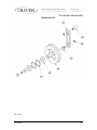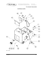
1
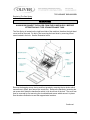
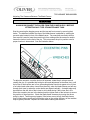
Grand Rapids, Michigan, U.S.A. 49504-5298
USER’S OPERATING AND INSTRUCTION MANUAL
MODEL 732-N
BREAD SLICER
0732S20000-CV
732-N FRONT LOAD SLICER
INDEX
Section Description
Document No.
Page No.
SAFETY INSTRUCTIONS -------------------------------------- 0732S20002 --------------------------- 1-1
DESCRIPTION/SPECIFICATIONS --------------------------- 0732S20003---------------------------- 2-1
Description -------------------------------------------------------------------------------------------------- 2-1
Specifications----------------------------------------------------------------------------------------------- 2-1
INSTALLATION INSTRUCTIONS ---------------------------- 0732S20004 --------------------------- 3-1
Slicer Installation ------------------------------------------------------------------------------------------ 3-1
OPERATING INSTRUCTIONS -------------------------------- 0732S20005 --------------------------- 4-1
TROUBLESHOOTING ------------------------------------------- 0732S20006 --------------------------- 5-1
The Slicer Will Not Start (Motor is Not Humming) ------------------------------------------------ 5-1
The Slicer Will Not Start (Motor is Humming) ------------------------------------------------------ 5-2
The Slicer Stops Before Slicing is Complete ------------------------------------------------------- 5-2
The Slicer Does Not Automatically Stop Upon Completion of Slicing ----------------------- 5-2
Bread Slices Vary in Thickness ------------------------------------------------------------------------ 5-3
The Blade Frames are Knocking ---------------------------------------------------------------------- 5-3
The Slicer Vibrates Excessively ----------------------------------------------------------------------- 5-3
The Hand Lever Pulls Hard ----------------------------------------------------------------------------- 5-3
The Bread is Cutting Slowly or is Being Damaged ----------------------------------------------- 5-4
MAINTENANCE --------------------------------------------------- 0732S20007 --------------------------- 6-1
Removing the Blade Frames --------------------------------------------------------------------------- 6-1
Replacing the Blade Frames --------------------------------------------------------------------------- 6-4
Changing the Blades ------------------------------------------------------------------------------------- 6-5
Tightening the Belt ---------------------------------------------------------------------------------------- 6-7
Replacing the Belt ---------------------------------------------------------------------------------------- 6-8
Replacing the Gas Spring ------------------------------------------------------------------------------ 6-9
Adjusting the Gas Spring ------------------------------------------------------------------------------ 6-12
Adjusting the Blade Frames When Slices Vary in Thickness -------------------------------- 6-13
Adjusting the Clearance Between the Blade Frames ------------------------------------------ 6-14
Lubrication ------------------------------------------------------------------------------------------------- 6-15
Cleaning ---------------------------------------------------------------------------------------------------- 6-15
RECOMMENDED SPARE PARTS -------------------------- 0732S20008 --------------------------- 7-1
REPLACEMENT PARTS SECTION
MAIN FRAME ---------------- ------------------------------------- 0732S20009 --------------------------- 8-1
Drawing ------------------------------------------------------------------------------------------------- 8-1
Parts List ----------------------------------------------------------------------------------------------- 8-2
Continued
0732S20001
0-1
732-N FRONT LOAD SLICER
INDEX (Continued)
REPLACEMENT PARTS SECTION (Continued)
Section Description
Document No.
Page No.
COVERS ------------------------------------------------------------ 0732S20010 --------------------------- 9-1
Drawing ------------------------------------------------------------------------------------------------ 9-1
Parts List ----------------------------------------------------------------------------------------------- 9-2
PUSHER ------------------------------------------------------------ 0732S20011 -------------------------- 10-1
Drawing ----------------------------------------------------------------------------------------------- 10-1
Parts List ---------------------------------------------------------------------------------------------- 10-2
ROCKER ----------------------------------------------------------- 0732S20012 -------------------------- 11-1
Drawing ----------------------------------------------------------------------------------------------- 11-1
Parts List ---------------------------------------------------------------------------------------------- 11-2
DRIVEN PULLEY ------------------------------------------------- 0732S20013 -------------------------- 12-1
Drawing ----------------------------------------------------------------------------------------------- 12-1
Parts List ---------------------------------------------------------------------------------------------- 12-2
SLICE PARTS ----------------------------------------------------- 0732S20014 -------------------------- 13-1
Drawing ----------------------------------------------------------------------------------------------- 13-1
Parts List ---------------------------------------------------------------------------------------------- 13-2
ELECTRICAL ------------------------------------------------------ 0732S20015 -------------------------- 14-1
Drawing ----------------------------------------------------------------------------------------------- 14-1
Parts List ---------------------------------------------------------------------------------------------- 14-2
WIRING DIAGRAM 1-60-115/230 --------------------------- 0732S20016 -------------------------- 15-1
WARRANTY ------------------------------------------------------- GEN 040228
WARRANTY PROCEDURE------------------------------------ GEN 040226
RETURNED PARTS POLICY --------------------------------- GEN 040227
0732S20001
0-2
732-N FRONT END SLICER
SAFETY INSTRUCTIONS
WARNING
VARIOUS SAFETY DEVICES AND METHODS OF GUARDING HAVE BEEN
PROVIDED ON THIS MACHINE. IT IS ESSENTIAL HOWEVER THAT THE MACHINE
OPERATORS AND MAINTENANCE PERSONNEL OBSERVE THE FOLLOWING
SAFETY PRECAUTIONS. IMPROPER INSTALLATION, MAINTENANCE, OR
OPERATION OF THIS EQUIPMENT COULD CAUSE SERIOUS INJURY OR DEATH.
1. Read this manual before attempting to operate your machine. Never allow an
untrained person to operate or service this machine.
2. Connect the machine to a properly grounded electrical supply that matches the
requirements shown on the electrical specification plate and follow all specifications
of local electrical codes.
3. Disconnect and lock-out the machine from the power supply before cleaning or
servicing.
4. Check and secure all guards before starting the machine.
5. Observe all caution and warning labels affixed to the machine.
6. Use only proper replacement parts.
7. Do not wear loose fitting clothing or loose hair when working near this machine.
Shirt tails should be tucked in.
8. Wear proper, personal, protective, safety equipment.
9. Keep Hands away from the moving parts of this machine while it is in operation.
10. In addition to these general safety instructions, please follow the more specific safety
instructions in the rest of this operating instruction manual.
WARNING
DO NOT USE FOR OTHER THAN ORIGINALLY INTENDED PURPOSE.
0732S20002
1-1
732-N FRONT END SLICER
DESCRIPTION/SPECIFICATIONS
Description
The Oliver Model 732-N Counter Top Bread Slicer is of a compact, sturdy, time tested
design, which has been used in bakeries worldwide for many years. The machine is
easy to operate and can be loaded and unloaded from the front of the machine. It is
capable of slicing either hard crusted breads or soft-textured sandwich loaves with ease
and precision. After slicing, the bread can be easily packaged with the use of its
convenient front mounted bagging scoop. Its design will provide years of efficient,
trouble-free operation requiring a minimum of maintenance.
The Model 732-N Bread Slicer is of stainless, plated, and painted steel construction for
easy cleaning and maintenance. As with other Oliver slicers it is so easy to change the
blades, when that becomes necessary, that most operators will feel comfortable enough
to do it themselves eliminating the need of a service call.
Oliver Products Company, who has a reputation of serving the Baking Industry for over
70 years, backs these slicers.
Specifications
Space Requirements:
Model 732-N (All Dimensions are Approximate)
0732S20003
2-1
732-N FRONT END SLICER
Product Capacities:
Length
Width
Height
16 Inches
5-1/2 inches (See Note)
5-1/2 inches (See Note)
NOTE
WIDTH AND HEIGHT DIMENSIONS ARE FOR A SQUARE PRODUCT. LOWER AND
WIDER PRODUCTS MAY ALSO BE SLICED BY TAKING CARE IN LOADING THE
PRODUCT. INDIVIDUAL DETERMINATIONS WOULD HAVE TO BE MADE.
Standard Electrical Options: (Others consult factory).
1 phase, 60 hz, 115VAC, 7 Amps.
1 phase, 60 hz, 230VAC, 3.5 Amps.
1 phase, 50 hz, 220VAC, 3.5 Amps.
Standard Slice Spacings,
7/16, 1/2, 9/16 (inches)
Optional Slice Spacings, (At additional cost). (Specials available -- consult factory).
3/8, 5/8, 11/16, 3/4, 13/16, 7/8, 1, 1-1/4 (inches)
Shipping Weight
300 lbs. (approximate)
Net Weight
250 lbs. (approximate)
0732S20003
2-2
732-N FRONT END SLICER
INSTALLATION INSTRUCTIONS
Slicer Installation:
Before starting the Installation process make sure you observe the following three
caution notes.
CAUTION
THE SLICER IS HEAVY, USE PROPER TECHNIQUE WHEN LIFTING.
KEEP BACK STRAIGHT, KNEES BENT, AND LIFT WITH LEGS.
USE GLOVES TO PROTECT HANDS.
CAUTION
NEVER LIFT THE SLICER BY ITS SIDE COVERS.
CAUTION
BEFORE PLACING THE SLICER ON THE TABLE OR COUNTER MAKE SURE THAT
IT CAN SUPPORT THE SLICER’S WEIGHT WHICH IS APPROX. 250 POUNDS.
Select a location for your slicer which has a substantial mounting surface, (see the
caution note above), and which has electrical service compatible with the load the
machine will place on it as indicated on the electrical data plate of the machine.
Position the machine while it is still in its packaging as close as possible to the desired
end location. Expose the machine by removing the outer packaging and remove its
crumb tray. Using at least two people, (one in the front and one at the back of the
machine), lift the slicer from the resting surface of the packaging and set the machine
onto the counter or table as close as possible to the desired end location. Make final
location adjustments by sliding the machine to its desired location.
0732S20004
3-1
732 FRONT END SLICER
OPERATING INSTRUCTIONS
WARNING
ALWAYS USE CARE WHENEVER WORKING NEAR THE CUTTING KNIVES.
To operate the slicer, stand in front of the machine and grasp the lever with your right
hand. Pull the lever all the way down and hold it in position. Using your left hand load
the product into the machine.
WARNING
NEVER START MACHINE BEFORE LOADING THE PRODUCT.
Make sure that the product does not hang over either edge of the cradle. While holding
the lever completely forward, (the machine will not start unless this is done), push the
Green “Start” button with your left hand.
After starting the machine restrain the hand lever slightly allowing it to return slowly until
the knives have contacted the AND penetrated the crust on the product. At this point
allow the lever to return at it’s own speed.
CAUTION
NEVER PUSH THE HAND LEVER.
0732S20005
4-1
732 FRONT END SLICER
Operating Instructions (Continued)
When the slicing operation is complete the machine will automatically stop. Once
stopped, remove the product from the cradle. Use of the standard front mounted
bagging scoop will ease packaging of your product.
The bagging scoop’s bread stop is adjustable to accommodate various size loaves. To
adjust, apply pressure to the outside edges of the bread stop and slide along the scoop
to the desired position.
0732S20005
4-2
732-N FRONT END SLICER
TROUBLE SHOOTING
WARNING
ALWAYS DISCONNECT THE SLICER FROM THE POWER SUPPLY BEFORE
ATTEMPTING ANY TYPE OF MAINTENANCE TASK, INCLUDING
TROUBLESHOOTING.
The Slicer Will Not Start (Motor Is Not Humming)
•
The machine is not plugged in.
•
There is no power at the outlet. (Check by plugging in a small working appliance,
like a lamp. Check to see if a circuit breaker has tripped. If the circuit breaker has
not tripped and the circuit is still not working have a qualified electrician check the
circuit.)
•
The Emergency “Stop” button has been pushed. Twist the Red button in the
direction of the arrow on the button to release it to its run position.
•
The lever is not being HELD in the forward most position.
•
There are bread crumbs beneath the cradle bracket or in the cradle guide tracks at
each side of the cradle bracket preventing it from going all the way down, which it
must do before the lower limit switch can be tripped.
•
The lower limit switch is not adjusted properly. (Have a qualified service agent
adjust the switch.)
•
The lower limit switch is defective. (Have a qualified electrician check and replace
the switch if required.)
•
The problem is somewhere else in the electrical system of the machine. (Have a
qualified electrician find and repair the problem.)
Continued
0732S20006
5-1
732-N FRONT END SLICER
Trouble Shooting (Continued)
The Slicer Will Not Start (Motor Is Humming)
CAUTION
DO NOT ALLOW THE MOTOR TO HUM WITHOUT STARTING.
OVERHEATING CAN PERMANENTLY DAMAGE THE MOTOR.
NOTE
A SPECIAL NON-VENTILATED MOTOR MUST BE USED WITH THIS SLICER.
•
The drive system is binding. (Have a qualified service agent check for defective
bearings or other restrictions to free movement.)
•
There is mechanical interference between other parts of the slicer. (Have a qualified
service agent evaluate the machine for adjustment or replacement of defective
parts.)
•
The motor has failed. (Have it checked by a qualified electrician.)
The Slicer Stops Before Slicing is Complete
•
The upper limit switch is not adjusted properly. (Have a qualified service agent
adjust the switch.)
The Slicer Does Not Automatically Stop Upon Completion of Slicing
•
The upper limit switch is not adjusted properly. (Have a qualified service agent
adjust the switch.)
•
The upper limit switch is defective. (Have a qualified electrician check and replace
the switch if required.)
•
A bread crust or other foreign object is preventing the cradle from returning to the top
of its travel.
Continued
0732S20006
5-2
732-N FRONT END SLICER
Trouble Shooting (Continued)
Bread Slices Vary in Thickness
•
The blade frames are out of adjustment. (See the “Maintenance” section of this
manual under “Adjusting the Blade Frames When Slices Vary in Thickness” on how
to correct this problem.)
The Blade Frames Are Knocking
•
The blade frames are out of adjustment. (See the “Maintenance” section of this
manual under “Adjusting the Clearance Between the Blade Frames” on how to
perform this adjustment.)
The Slicer Vibrates Excessively
•
The drive belt is loose or worn. (See the “Maintenance” section of this manual under
“Tightening the Belt” or “Replacing the Belt” on how to make these corrections.)
•
One or more of the bearings on the machine are failing. (Have a qualified service
agent check for defective bearings and replace them as required.)
•
The pins, (two eccentrics and two regular), and links at the top of the blade frames
are worn. We suggest that these be replaced together. Mixing worn parts with new
will shorten the life of the replacement parts. Remember, after replacing the pins
and links the clearance between the blade frames must be re-adjusted. (See the
“Maintenance” section of this manual under “Adjusting the Clearance Between the
Blade Frames” on how to perform this adjustment.)
The Hand Lever Pulls Hard
•
Check the Cradle guide tracks at each end of the cradle bracket for a build-up of
foreign material.
Continued
0732S20006
5-3
732-N FRONT END SLICER
Trouble Shooting (Continued)
The Bread is Cutting Slowly or is Being Damaged
•
The product you are attempting to slice is below the minimum height capacity of the
machine.
•
You are pushing the lever of the machine in an attempt to speed slicing. This may
not only damage the product but may also damage the machine.
•
If only certain products are cutting slowly the cutting speed you are experiencing may
be normal for that particular product.
•
The knives of the machine have become worn, (dull). (See the “Maintenance” section
of this manual under “Changing the Cutting Knives”). Most owners can perform this
item of maintenance without calling a service company.
•
The blades are not aligned properly. (See the “Maintenance” section of this manual
under “Adjusting the Clearance Between the Blade Frames” on how to perform this
adjustment.)
•
The Gas spring may require adjustment or replacement. (See the Maintenance
section of this manual under “Gas Spring Replacement” on how to perform this task.)
0732S20006
5-4
732-N FRONT END SLICER
MAINTENANCE
Removing The Blade Frames
WARNING
ALWAYS UNPLUG THE SLICER BEFORE PERFORMING
ANY TYPE OF MAINTENANCE TASK.
Remove the bagging scoop, the top and front covers by removing the ten knobs which
secure them. Only remove the infeed table in the event that you MUST remove the
lower blade frame. See the note below.
NOTE
REMOVAL OF THE LOWER BLADE FRAME IS NOT REQUIRED
TO CHANGE ITS BLADES
Should it be necessary to remove the lower blade frame you must first remove the infeed
table by removing the two knobs which secure it in place and then by pulling the table
down out of the clips and out through the infeed opening. See above illustration.
Continued
0732S20007
6-1
732-N FRONT END SLICER
Removing The Blade Frames (Continued)
NOTE
DO NOT LOOSEN THE NUTS WHICH SECURE THE ECCENTRIC PINS.
Pull the clip from the eccentric pin and slide the link toward the eccentric pin mounting
plate. See the illustration below.
After removing the pair of locking cams, eyebolts and Belleville washers, (which secure
each blade frame to the rocker’s swing shaft), the blade frame can be lifted from the
machine. The eyebolts and Belleville washers can be removed by turning them counter
clockwise once the cams have been removed.
Continued
0732S20007
6-2
732-N FRONT END SLICER
Removing The Blade Frames (Continued)
WARNING
BLADES ARE EXTREMELY SHARP ALWAYS HANDLE
BLADE FRAMES WITH CARE.
Carefully lift the upper blade frame from the slicer.
NOTE
REMOVAL OF THE LOWE BLADE FRAME IS NOT REQUIRED
TO CHANGE ITS BLADES
If you must remove the lower blade frame, remove the infeed table as described above,
then with the cradle in its normal position remove the two cams, eyebolts, Belleville
washers, clip and link from the lower blade frame just as it was done above for the upper
blade frame.
0732S20007
6-3
732-N FRONT END SLICER
Replacing The Blade Frames
WARNING
ALWAYS DISCONNECT THE SLICER FROM THE POWER SUPPLY BEFORE
ATTEMPTING ANY TYPE OF MAINTENANCE TASK.
Replacement of the blade frames is done by reversing the removal procedures. Ensure
that the feet of the blade frames rest snuggly on the swing shafts and that you have
included the Belleville washers with the eye bolts.
NOTE
WHEN INSTALLING THE BELLEVILLE WASHERS, THEY MUST BE PLACED
SO THAT THE CROWN IS UP AS SHOWN IN THE ILLUSTRATION BELOW.
When replacing the eye bolts turn them clockwise until moderate pressure is required to
close the cam. If the cam is to easy to close rotate the eye bolt a half turn more in the
clockwise direction and try to reinstall the cam. Repeat these partial rotations until
moderate pressure is required to close the cam. If the cams are either difficult or
impossible to close, rotate the eye bolt a half turn in the counter clockwise direction.
Repeating until the cams can be closed using moderate pressure.
0732S20007
6-4
732-N FRONT END SLICER
Changing The Blades
WARNING
ALWAYS DISCONNECT THE SLICER FROM THE POWER SUPPLY BEFORE
ATTEMPTING ANY TYPE OF MAINTENANCE TASK.
WARNING
BLADES ARE EXTREMELY SHARP ALWAYS HANDLE WITH CARE.
NOTE
WHEN REPLACING ALL THE BLADES, ALWAYS REMOVE AND REPLACE
ONE BLADE AT A TIME. NEVER REMOVE ALL THE BLADES AT ONCE AND
THEN ATTEMPT TO REPLACE THEM ALL AT ONCE.
CAUTION
NEVER PUT BLADE FRAMES IN THE SLICER WITHOUT KNIVES.
First remove the upper blade frame from the machine, see “Removing the Blade
Frames” above. You may use the special knife tools, shown in the illustrations on the
next pages, or use a common set of pliers to decrease the tension on the blade. By
lifting up on the tool as shown below, tension will be reduced on the blade so that it can
be carefully removed. Remember you do not need to remove the lower blade frame to
replace its blades.
Rev. 2/15/05
0732S20007
Continued
6-5
732-N FRONT END SLICER
Changing The Blades (Continued)
The new knife can be installed in the upper blade frame by reversing the removal
procedure. A paper clip can be used to hold the knife in position on the lower pin to
ease installation. See the illustration below. Remember to make sure that the sharp
edge of the blade is pointing in the same direction as the edge on the blade which was
just removed. Also remember to remove and replace one blade at a time.
The blades can be removed from the lower blade frame while it is still in the machine.
This is done by using a second special blade changing tool. Insert the tool into the blade
frame, push the handle toward the feet of the blade frame as shown below. This will
reduce the tension on the blade so that it can be carefully removed.
Using the same technique as used on the upper blade frame, replace the knives in the
lower blade frame.
0732S20007
6-6
732-N FRONT END SLICER
Tightening the Belt
WARNING
ALWAYS DISCONNECT THE SLICER FROM THE POWER SUPPLY BEFORE
ATTEMPTING ANY TYPE OF MAINTENANCE TASK.
CAUTION
OVER-TIGHTENING THE DRIVE BELT MAY
CAUSE BEARING OR MOTOR FAILURE.
Remove the top cover by removing the six knobs which secure it. Then using a wrench
loosen, but do not remove, the four nuts which secure the motor mounting plate to the
machine.
CAUTION
DO NOT REMOVE THE MOTOR PLATE NUTS COMPLETELY.
Manually lift the motor upward to tighten the belt using care to keep the centerline of the
motor perpendicular to the centerline of the belt. The belt can be loosened by carefully
moving the motor downward. The drive belt should be just tight enough, using moderate
finger pressure, to allow a 3/8 inch deflection halfway between the motor drive pulley
and the driven pulley. When desired belt tension is achieved, retighten the motor
mounting nuts securely and replace the top cover.
0732S20007
6-7
732-N FRONT END SLICER
Replacing the Belt
WARNING
ALWAYS DISCONNECT THE SLICER FROM THE POWER SUPPLY BEFORE
ATTEMPTING ANY TYPE OF MAINTENANCE TASK.
Remove the top cover by removing the six knobs which secure it. Using a wrench,
loosen but do not remove the four nuts which secure the motor mounting plate to the
machine. Move the motor and its mounting plate downward as far as it will go allowing
the belt to loosen as much as possible. (See “Tightening the Belt” section).
CAUTION
DO NOT REMOVE THE MOTOR PLATE NUTS COMPLETELY.
Disconnect the end of the connecting rod attached to the rocker by removing the two hex
cap screws and rod cap which secure the connecting rod to the rocker. Once this has
been done you should be able to remove the belt.
After replacing the belt reattach the connecting rod making sure to place the connecting
rod as perpendicular as possible to the rocker’s main shaft. Retighten the rod cap’s
bolts securely. Tighten the belt as described in the “Tightening the Belt” section of this
manual and then replace the top cover.
0732S20007
6-8
732-N FRONT END SLICER
Replacing The Gas Spring
WARNING
ALWAYS DISCONNECT THE SLICER FROM THE POWER SUPPLY BEFORE
ATTEMPTING ANY TYPE OF MAINTENANCE TASK.
The Gas Spring is located on the right hand side of the machine, therefore the right hand
cover must be removed. Do this by first removing the hand lever by removing its set
screw located in the hub. See the illustration below.
Remove the bagging scoop, the top and front guards by removing the ten knobs which
secure them in place, also remove the crumb tray. Remove the handle by loosening the
set screw which holds the handle after which it can be slid out of the hub. The cover can
then be removed by first removing the six slotted head screws which secure it in place.
See the above illustration to see their approximate locations.
Continued
0732S20007
6-9
732-N FRONT END SLICER
Replacing the Gas Spring (Continued)
WARNING
THE GAS SPRING IS IN A COMPRESSED STATE, USE
CARE WHEN REMOVING IT FROM THE MACHINE.
To remove the gas spring, remove the push-on clip at the top of the gas spring by prying
it off with a screw driver.
NOTE
THE CLIP IS NOT REUSUABLE; A NEW ONE WILL BE REQUIRED.
After the clip is removed, the gas spring can then be pried off with a screwdriver, use
care noting the above warning. See the next illustration for additional information. After
the spring is off the pin the shoulder screw securing the lower end of the spring can be
removed freeing the spring.
Install a gas spring by first attaching the lower end of the spring to the pusher arm with
the shoulder screw.
CAUTION
USE A LOCKING FLUID, SUCH AS LOC-TITE ®, TO PREVENT THE
SCREW FROM LOOSENING BECAUSE OF VIBRATION.
Continued
0732S20007
6-10
732-N FRONT END SLICER
Replacing the Gas Spring (Continued)
Using two people, grasp the spring as shown in the next illustration and slide the gas
spring over the same upper pin that the old gas spring was removed from. See the
caution statement below. After this is complete install the new clip and replace all of the
covers. Lastly reinstall the hand lever.
CAUTION
CARE MUST BE USED WHEN WORKING WITH THE GAS SPRING.
ALWAYS PUSH STRAIGHT DOWN OR SPRING DAMAGE MAY OCCUR.
0732S20007
6-11
732-N FRONT END SLICER
Adjusting The Gas Spring
WARNING
ALWAYS DISCONNECT THE SLICER FROM THE POWER SUPPLY BEFORE
ATTEMPTING ANY TYPE OF MAINTENANCE TASK.
CAUTION
FREQUENT ADJUSTMENT OF THE GAS SPRING IS NOT RECOMMENDED.
The gas spring must be removed and relocated to adjust its force. To remove the gas
spring, see “Replacing the Gas Spring” above. There are two gas spring pins welded to
the frame. The pin furthest from the front of the machine, (the standard position), should
be used whenever possible. The standard position gives a gentle force at the beginning
of the slicing operation, (when it is most needed), which will allow the knives to start
cutting and prevent damage to the product. It also provides the most force at the end of
the stroke to allow the cradle to finish its upward travel and the machine to shut off.
The pin located in the high forward position should be used when greater force is
desired as the product is first entering the knives.
NOTE
NORMALLY DIFFICULT CUTTING BREADS REQUIRE LESS FORCE AT THE
BEGINNING OF SLICING RATHER THAN MORE.
Using proper gas spring installation procedures, see “Replacing the Gas Spring”’ above,
compress the spring and mount it on the desired pin. Secure it with a new clip.
0732S20007
6-12
732-N FRONT END SLICER
Adjusting The Blade Frames When Slices Vary In Thickness
WARNING
ALWAYS DISCONNECT THE SLICER FROM THE POWER SUPPLY BEFORE
ATTEMPTING ANY TYPE OF MAINTENANCE TASK.
Assuming that the lower blade frame has been installed and centered in the machine,
meaning that it has been aligned with the slots in the top cover and holddown, and
secured with the locking cams, proceed as follows to adjust the upper blade frame. If
the lower blade frame has not been centered the same process to be described for
adjusting the upper blade frame should be used to center and secure the lower blade
frame before you proceed.
To adjust the upper blade frame loosen both locking cams, and also loosen the set
screw securing the “Locking Collar”. Once this is done take a small hammer or mallet
and tap the blade frame either to the right or left to equalize the distances between the
blades. Once this is done secure the locking collar with the set screw and retighten the
locking cams. After the covers have been replaced the machine should be ready to use.
0732S20007
6-13
732-N FRONT END SLICER
Adjusting The Clearance Between The Blade Frames
WARNING
ALWAYS DISCONNECT THE SLICER FROM THE POWER SUPPLY BEFORE
ATTEMPTING ANY TYPE OF MAINTENANCE TASK.
Start by removing the bagging scoop and the top and front covers by removing their
knobs. The distance between the tops of the blade frames is adjusted by rotating the
eccentric pins located in front of the blade frames. Two wrenches are used to do this.
One wrench is used to keep the eccentric pin from rotating while the second is used to
loosen the lock nut on the end of the pin. This nut secures the pin in position once its
proper location is determined. See the illustration below.
To adjust the eccentric, once the lock nut is loosened, rotate the pin using a wrench,
rotating the pin, (it is possible that both pins will need adjustment at the same time), until
the knives of the machine are in line, (alternating blades should not appear to be in front
of or behind each other when viewed from the side), when the blade frames are half way
through their travel or when the rocker shafts are aligned vertically. A straight edge may
be used from the dull side of the knives to aid in determining if the knives are in line.
When the eccentric pins are in the desired position tighten each of the locknuts to secure
the position of the eccentrics. Check the blade frame clearance by turning the driven
pulley by hand. Two things may happen if the knives are not inline, the blade frames
may hit each other causing a loud knocking noise or the cutting efficiency of the machine
may be greatly reduced. Replace all covers before starting the machine.
0732S20007
6-14
732-N FRONT END SLICER
Lubrication
WARNING
ALWAYS DISCONNECT THE SLICER FROM THE POWER SUPPLY BEFORE
ATTEMPTING ANY TYPE OF MAINTENANCE TASK.
Once a month put a drop of a food approved lubricant on the plastic links at the top of
the blade frames. Also add a drop or two to each bushing on the pusher drive cross
shaft and lever shaft. All other bearings are either grease packed or sealed and seldom
need attention.
NOTE
NEVER OIL OR GREASE THE MOTOR.
Cleaning
Use a mild detergent solution to clean the exterior surfaces and empty the crumb tray
daily or as necessary. Periodically remove all covers and brush or blow, (if compressed
air is available), all foreign material from all surfaces, especially moving parts.
0732S20007
6-15
732-N FRONT END SLICER
RECOMMENDED SPARE PARTS
PART NUMBER
PART DESCRIPTION
NO. REQ’D
5835-7705
Clip-Hairpin
2
0730-0031
Pin-Eccentric
2
0732-0013
Pin-Blade Frame
2
0711-0002
Link-Top
2
6301-3609*
Motor-1/2 HP, 1-60-115/230
1
5601-1127*
Belt-V (4L370) (60 Cycle Machines)
1
5749-8027*
Relay-Power (115 VAC)
1
5749-8028*
Relay-Power (230 VAC)
1
5708-7915
Red “Stop” Pushbutton
1
5708-7931
“Stop” Contact Block
1
5708-7900
Green “Start” Pushbutton
1
5708-7930
“Start” Contact Block
1
5757-7354
Switch-Limit
2
5220-5040
Bearing-Driven Pulley
2
0797-0058-019
Stud-Driven Pulley
1
0797-0071-4
Connecting Rod Assembly with Bearings
1
0797-0057-219
Stud-Swing
1
5220-4040
Bearing-Rocker Shaft
2
5220-0020
Bearing-Swing Shaft
4
0797-0029-1
Knife-Type A
0777-0970
Bolt-Eye
4
0777-0971
Cam-Clamp
4
5852-0050
Spring-Bellville
4
6084-8700
Gas Spring
1
5831-8225
Clip-Push On
2
5251-0030
Bearing-5/8 Cam Follower
2
5251-0091
Bearing-3/4 Cam Follower
1
As Req’d.
*For Other Electrics Contact the Factory
For Service Parts Call Oliver Products @ 800-253-3893
REV 1-20-09
0732S20008
7-1
732-N FRONT END SLICER
MAIN FRAME
REV 10/3/08
0732S20009
8-1
732-N FRONT END SLICER
MAIN FRAME PARTS LIST
ITEM NO
PART DESCRIPTION
PART NUMBER
001
001
Frame
Frame (Black)
0732-0002
0732-0002-002
002
Leg-Extension
0732-0003
003
Bumper-Rubber
5902-0036
006
Angle-RH Mounting
0732-0004-0001
007
Angle-LH Mounting
0732-0004-0002
009
Table-Infeed
0711-0048
010
Knob W/Stud M5 x .8 x 15mm LG
5911-7210
011
Pin-Eccentric
0730-0031
014
Link-Blade Frame
0711-0002
015
Clip-Hairpin
5835-7705
NOTE: Bold text represents optional parts available
FOR SERVICE PARTS CALL OLIVER PRODUCTS @ 800-253-3893
REV. 10/3/08
0732S20009
8-2
732-N FRONT END SLICER
COVERS
104
113
105
103
102
106
101
107
109
108
112
REV. 7/22/04
0732S20010
9-1
732-N FRONT END SLICER
COVERS PARTS LIST
ITEM NO
PART DESCRIPTION
PART NUMBER
101
Cover-Front
0732-0005
102
Knob-Clamp W/Stud M6 x 1
4560-2507-18
103
Knob-Clamp W/Stud M5 x .8 x 15MM LG
5911-7210
104
Scoop-Bread
0711-0004-1
105
Stop-Bread
0711-0080
106
Washer-Flat Nylon
5851-8120
107
Tray-Crumb
0711-0014-002
108
108
Cover-RH Side
Cover-RH Side (Black)
0732-0006
0732-0006-002
109
108
Cover-LH Side
Cover-LH Side (Black)
0732-0007
0732-0007-002
112
112
Cover-Electrical Box
Cover-Electrical Box (Black)
0732-0008
0732-0008-002
113
Cover-Switch Enclosure
0732-0009
NOTE: Bold text represents optional part available
FOR SERVICE PARTS CALL OLIVER PRODUCTS @ 800-253-3893
REV. 1/30/07
0732S20010
9-2
732-N FRONT END SLICER
PUSHER
REV. 11/21/08
0732S20011
10-1
732-N FRONT END SLICER
PUSHER PARTS LIST
ITEM NO
201
202
203
204
209
211
212
213
214
215
217
218
220
221
222
226
227
228
229
230
231
233
PART DESCRIPTION
PART NUMBER
Shaft-Pusher (Metric)
Bearing-Bronze Flange
Arm-LH Pusher
Key
Arm-RH Pusher
Spring-Gas
Spacer-Lower
Clip-Push on
Screw-Shoulder ¼ x ¼
Spindle Assembly M8 x 1.25
Bracket-Cradle Mounting
Block-Slide
Bearing-5/8 Dia. Cam Follower
Guide-RH Pusher
Guide-LH Pusher
Hub-Pusher Drive
Washer-Special
Bearing-3/4 Dia. Cam Follower
Bearing-Bronze Flange
Lever-Pusher
Knob-Ball
Keeper
0732-0010
5254-3043
0711-0042
5824-2316
0711-0043-2
6084-8700
0711-0021
5831-8225
5842-8501
5902-8795
0732-0011
0711-0017
5251-0030
0711-0051-0001
0711-0051-0002
0732-0023
4655-0309-1603
5251-0091
5254-3139
0732-0024
5911-7120
0711-0023
FOR SERVICE PARTS CALL OLIVER PRODUCTS @ 800-253-3893
REV. 11/21/08
0732S20011
10-2
732-N FRONT END SLICER
ROCKER
REV. 8/11/08
0732S20012
11-1
732-N FRONT END SLICER
ROCKER
PARTS LIST
ITEM NO
PART DESCRIPTION
PART NUMBER______QUANTY
301
Frame-Rocker
0732-0012-001
1
302
Bearing-Ball
5220-4040
2
303
Spacer-Bearing
0797-3088-001
1
304
Ring-Retaining
5840-1036
2
305
Screw-Hex Hd M6x16MM
8842-0544
2
306
Washer-Flat- 1x1/4x1/8
8851-8495
2
307
Washer-Spring Lock M6
8851-9414
2
308
Shaft-Swing
0730-0024-001
2
310
Bearing-Ball 10x30x9
5220-0042
4
312
Nut- Hx HD Jam M10x1.5
8832-0418
4
314
Collar-Hold Down
0797-0031-002
2
315
Collar-Locating
0797-0031-003
2
316
Rod-Threaded 3/8-16 Nylon 5840-8076
2
317
Screw-Socset Cuppt 3/8x1/4 5842-6156
2
318
Cap-Clamp
0730-0023
1
319
Screw- Hx HD M10x40MM
8843-0331
2
320
Washer- Spring Lock M10
8851-9468
2
(All Washers, Screws, & Nuts on this list are Stainless Steel
FOR SERVICE PARTS CALL OLIVER PRODUCTS @ 800-253-3893
REV. 8/11/08
0732S20012
11-2
732-N FRONT END SLICER
DRIVEN PULLEY
REV. 1/20/09
0732S20013
12-1
732-N FRONT END SLICER
DRIVEN PULLEY PARTS LIST
ITEM NO
PART DESCRIPTION
PART NUMBER
401
Pulley-Driven
0730-0005-001
402
Stud
0797-0058-019
403
Stud-Swing
0797-0057-219
404
Rod Assembly W/Bearings
0797-0071-4
405
Ring-Retaining
5840-2825
406
Bearing-Ball
5220-5040
407
Ring-Retaining
5840-1040
408
Washer-Flat M10
8851-8418
409
Washer-Spring Lock M10
8851-9418
410
Screw-Hex HD M10 X 20MM
8842-0583
FOR SERVICE PARTS CALL OLIVER PRODUCTS @ 800-253-3893
REV. 1/20/09
0732S20013
12-2
732-N FRONT END SLICER
SLICE PARTS
REV. 7/22/04
0732S20014
13-1
732-N FRONT END SLICER
SLICE PARTS LIST
ITEM NO
PART DESCRIPTION
PART NUMBER
501*
Blade Frame
0732-0001-5XX
502
Pin-Frame
0732-0013
503
Bolt-Eye
0777-0970
504
Cam
0777-0971
505
Blade-Type A
0797-0029-1
506
Washer-Belleville Spring
5852-0050
510*
Holddown
0711-0036-2XX
511
Bushing
0777-0066
512
Screw-Pivot
0777-0068-001
513
Spring-RH Torsion
7030-0020
514
Spring-LH Torsion
7030-0021
515*
Cradle
0732-0014-1XX
516
Knob-Knurled
5911-7218
517*
Cover-Top
0732-0015-0XX
518
Knob W/Stud M5 x .8 x 15mm Lg.
5911-7210
* Specify Slice Thickness
FOR SERVICE PARTS CALL OLIVER PRODUCTS @ 800-253-3893
Rev. 8/11/04
0732S20014
13-2
732-N FRONT END SLICER
ELECTRICAL PARTS
REV. 12/13/05
0732S20015
14-1
732-N FRONT END SLICER
ELECTRICAL PARTS LIST
ITEM NO
PART DESCRIPTION
PART NUMBER
801
Plate-Motor Mounting
0732-0016
805*
805*
Motor-1/2 HP 1-60-115/230
Motor-1/2 HP 1-50-110/220
6301-3609
6301-3940
807
808
Bushing-Strain Relief
Bushing-Strain Relief
5765-1082
5765-1120
811
811
Pulley-V Belt (60 Hz Machines)
Pulley-V Belt (50 Hz Machines)
0732-0018
0732-0018-002
812
814
815
816
818
819
821
822
825
826
827
Rod-Nylon Threaded ¼-20
Belt-V 4L370
Button-Red Stop
Block-“Stop” Contact
Button-Green Start
Block “Start” Contact
Bushing-Strain Relief
Clamp-Cable
Switch-Limit
Nutbar-Switch Mounting
Bushing-Strain Relief
5840-8074
5601-1127
5708-7915
5708-7931
5708-7900
5708-7930
5765-1010
5765-4232
5757-7357
0732-0020
5765-1110
834
834
Relay-Power 1-50/60-110/115
Relay-Power 1-50/60-220/230
5749-8027
5749-8028
835
836
838
841
Block-Terminal
Strip-Marker
Plug-Hole
Green Grounding Screw 6-32 3/8”
5770-7451
5770-7328
5769-3008
5841-9501
*
For other Electrics Consult the Factory
Continued
FOR SERVICE PARTS CALL OLIVER PRODUCTS @ 800-253-3893
REV 10/5/06
0732S20015
14-2
732-N FRONT END SLICER
ELECTRICAL PARTS LIST (Continued)
Items Not Shown On Drawing
ITEM NO
PART DESCRIPTION
PART NUMBER
806
817
820
830
831
Cord-Motor
Wire-Switch Jumper
Cord-Pushbutton
Cord-Stop Limit Switch
Cord-Start Limit Switch
0732-0017
0711-0059
0732-0019
0732-0021
0732-0022
832*
832*
Cord Power 1-60-115
Cord Power 1-60-230 & 1-50-110/220
0711-0056
0711-0056-001
833
838
839*
840
843
Harness-Wire
Plug-Hole
Nameplate-Wiring Diagram (Single Phase)
Plug-Power 1-60-230
Plug-Hole
0711-0057
5769-3008
6402-3103
5765-2030
5769-3013
*
For other Electrics Consult the Factory
FOR SERVICE PARTS CALL OLIVER PRODUCTS @ 800-253-3893
REV. 12/13/05
0732S20015
14-3
732-N FRONT END SLICER
WIRING DIAGRAM 1-60-115/230 & 1-50-110/220
•
For other Electrics Consult the Factory
0732S20016
15-1
WARRANTY
PARTS
Oliver Packaging & Equipment Company (Oliver) warrants that if any part of the equipment (other
than a part not manufactured by Oliver) proves to be defective (as defined below) within two years
after shipment, and if Buyer returns the defective part to Oliver within one year, Freight Prepaid to
Oliver’s plant in Grand Rapids, MI, then Oliver, shall, at Oliver’s option, either repair or replace the
defective part, at Oliver’s expense.
LABOR
Oliver further warrants that equipment properly installed in accordance with our special instructions,
which proves to be defective in material or workmanship under normal use within one (1) year from
installation or one (1) year and three (3) months from actual shipment date, whichever date comes
first, will be repaired by Oliver or an Oliver Authorized Service Dealer, in accordance with Oliver’s
published Service Schedule.
For purposes of this warranty, a defective part or defective equipment is a part or equipment which is
found by Oliver to have been defective in materials workmanship, if the defect materially impairs the
value of the equipment to Buyer. Oliver has no obligation as to parts or components not
manufactured by Oliver, but Oliver assigns to Buyer any warranties made to Oliver by the
manufacturer thereof.
This warranty does not apply to:
1. Damage caused by shipping or accident.
2. Damage resulting from improper installation or alteration.
3. Equipment misused, abused, altered, not maintained on a regular basis, operated carelessly, or
used in abnormal conditions.
4. Equipment used in conjunction with products of other manufacturers unless such use is approved
by Oliver Products in writing.
5. Periodic maintenance of equipment, including but not limited to lubrication, replacement of wear
items, and other adjustments required due to installation, set up, or normal wear.
6. Losses or damage resulting from malfunction.
The foregoing warranty is in lieu of all other warranties expressed or implied AND OLIVER MAKES
NO WARRANTY OF MERCHANTABILITY OR FITNESS FOR PURPOSE REGARDING THE
EQUIPMENT COVERED BY THIS WARRANTY. Oliver neither assumes nor authorizes any person
to assume for it any other obligations or liability in connection with said equipment. OLIVER SHALL
NOT BE LIABLE FOR LOSS OF TIME, INCONVENIENCE, COMMERCIAL LOSS, INCIDENTAL OR
CONSEQUENTIAL DAMAGES.
GEN 040228
WARRANTY PROCEDURE
1. If a problem should occur, either the dealer or the end user must contact the Parts and
Service Department and explain the problem.
2. The Parts and Service Manager will determine if the warranty will apply to this particular
problem.
3. If the Parts and Service Manager approves, a Work Authorization Number will be
generated, and the appropriate service agency will perform the service.
4. The service dealer will then complete an invoice and send it to the Parts and Service
Department at Oliver Products Company.
5. The Parts and Service Manager of Oliver Packaging and Equipment Company will
review the invoice and returned parts, if applicable, and approve for payment.
GEN 040226
RETURNED PARTS POLICY
This policy applies to all parts returned to the factory whether for warranted credit,
replacement, repair or re-stocking.
Oliver Packaging and Equipment Company requires that the customer obtain a Return
Material Authorization (RMA) number before returning any part. This number should appear
on the shipping label and inside the shipping carton as well. All parts are to be returned
prepaid. Following this procedure will insure prompt handling of all returned parts.
To obtain an RMA number contact the Repair Parts Deptartment toll free at (800) 253-3893.
Parts returned for re-stocking are subject to a RE-STOCKING CHARGE.
Thank you for your cooperation,
Repair Parts Manager
Oliver Packaging and Equipment Company
GEN 040227