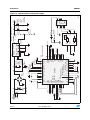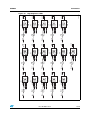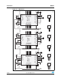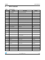
1
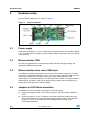
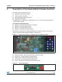
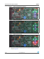
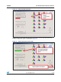
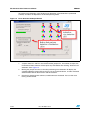
UM0882
User manual
STEVAL-ILL028V1 LED dimmer board
using STP1612PW05 and STM32™
1
Introduction
This user manual describes STMicroelectronics™ STEVAL-ILL028V1 LED dimmer board.
This board is based on STP1612PW05 independent PWM LED driver controlled through
STM32 microcontroller SPI interface and DMA (optional).
This document explains how to use the board: hardware setup, demonstration firmware
functions, possible interconnections with PC and evaluation of STP1612PW05.
Figure 1.
July 2010
STEVAL-ILL028V1 LED dimmer board
Doc ID 16881 Rev 2
1/20
www.st.com
Contents
UM0882
Contents
1
Introduction . . . . . . . . . . . . . . . . . . . . . . . . . . . . . . . . . . . . . . . . . . . . . . . . 1
2
Board function overview . . . . . . . . . . . . . . . . . . . . . . . . . . . . . . . . . . . . . 5
3
Hardware setup . . . . . . . . . . . . . . . . . . . . . . . . . . . . . . . . . . . . . . . . . . . . . 6
4
3.1
Power supply . . . . . . . . . . . . . . . . . . . . . . . . . . . . . . . . . . . . . . . . . . . . . . . 6
3.2
Microcontroller JTAG . . . . . . . . . . . . . . . . . . . . . . . . . . . . . . . . . . . . . . . . . 6
3.3
Microcontroller clock, reset, USB clock . . . . . . . . . . . . . . . . . . . . . . . . . . . 6
3.4
Jumpers for LED failure simulation . . . . . . . . . . . . . . . . . . . . . . . . . . . . . . . 6
Description of the demonstration firmware functions . . . . . . . . . . . . . . 7
4.1
Mode “A” - interactive demonstration - color Tetris . . . . . . . . . . . . . . . . . . . 8
4.2
Mode “B” - wave color demonstration . . . . . . . . . . . . . . . . . . . . . . . . . . . . . 8
4.3
Mode “C” - solid color demonstration . . . . . . . . . . . . . . . . . . . . . . . . . . . . . 8
4.4
Mode “D” - error detection . . . . . . . . . . . . . . . . . . . . . . . . . . . . . . . . . . . . . 8
5
PC demonstration firmware software . . . . . . . . . . . . . . . . . . . . . . . . . . . 9
6
Schematics . . . . . . . . . . . . . . . . . . . . . . . . . . . . . . . . . . . . . . . . . . . . . . . 13
7
Bill of material . . . . . . . . . . . . . . . . . . . . . . . . . . . . . . . . . . . . . . . . . . . . . 17
8
Revision history . . . . . . . . . . . . . . . . . . . . . . . . . . . . . . . . . . . . . . . . . . . 19
2/20
Doc ID 16881 Rev 2
UM0882
List of tables
List of tables
Table 1.
Table 2.
Bill of material . . . . . . . . . . . . . . . . . . . . . . . . . . . . . . . . . . . . . . . . . . . . . . . . . . . . . . . . . . . 17
Document revision history . . . . . . . . . . . . . . . . . . . . . . . . . . . . . . . . . . . . . . . . . . . . . . . . . 19
Doc ID 16881 Rev 2
3/20
List of figures
UM0882
List of figures
Figure 1.
Figure 2.
Figure 3.
Figure 4.
Figure 5.
Figure 6.
Figure 7.
Figure 8.
Figure 9.
Figure 10.
Figure 11.
Figure 12.
Figure 13.
Figure 14.
Figure 15.
Figure 16.
4/20
STEVAL-ILL028V1 LED dimmer board . . . . . . . . . . . . . . . . . . . . . . . . . . . . . . . . . . . . . . . . 1
Setup of the board . . . . . . . . . . . . . . . . . . . . . . . . . . . . . . . . . . . . . . . . . . . . . . . . . . . . . . . . 6
The menu; the letter “A” indicates the first item of the menu . . . . . . . . . . . . . . . . . . . . . . . . 7
The control buttons . . . . . . . . . . . . . . . . . . . . . . . . . . . . . . . . . . . . . . . . . . . . . . . . . . . . . . . . 7
Simulation of LED defect by setting/removing P21 to P2 jumpers . . . . . . . . . . . . . . . . . . . . 8
Software - Windows® application . . . . . . . . . . . . . . . . . . . . . . . . . . . . . . . . . . . . . . . . . . . . . 9
USB host (PC) detection in progress . . . . . . . . . . . . . . . . . . . . . . . . . . . . . . . . . . . . . . . . . 10
USB host (PC) detected . . . . . . . . . . . . . . . . . . . . . . . . . . . . . . . . . . . . . . . . . . . . . . . . . . . 10
USB host (PC) not found . . . . . . . . . . . . . . . . . . . . . . . . . . . . . . . . . . . . . . . . . . . . . . . . . . 10
Manual board connection . . . . . . . . . . . . . . . . . . . . . . . . . . . . . . . . . . . . . . . . . . . . . . . . . . 11
Board connected successfully . . . . . . . . . . . . . . . . . . . . . . . . . . . . . . . . . . . . . . . . . . . . . . 11
Error detection mode performed . . . . . . . . . . . . . . . . . . . . . . . . . . . . . . . . . . . . . . . . . . . . . 12
Connectors, buttons, UART . . . . . . . . . . . . . . . . . . . . . . . . . . . . . . . . . . . . . . . . . . . . . . . . 13
Microcontroller, USB, power supply . . . . . . . . . . . . . . . . . . . . . . . . . . . . . . . . . . . . . . . . . . 14
High brightness LEDs . . . . . . . . . . . . . . . . . . . . . . . . . . . . . . . . . . . . . . . . . . . . . . . . . . . . . 15
LED drivers . . . . . . . . . . . . . . . . . . . . . . . . . . . . . . . . . . . . . . . . . . . . . . . . . . . . . . . . . . . . . 16
Doc ID 16881 Rev 2
UM0882
2
Board function overview
Board function overview
The STEVAL-ILL028V1 demonstration board features:
●
Three STP1612PW05 (QFN24 4 x 4 mm) connected to 16 RBG LEDs
●
16 RGB high brightness LEDs
●
One STM32 microcontroller using internal HS oscillator
●
An ST1S10: a high-efficiency switching DC-DC power supply
●
7.5 - 18 V DC power supply with undifferentiated polarity and overvoltage protection
●
DC input current 0.7 A max., standard supply connector
●
LED current regulation
●
The board can be controlled by 3 buttons, a knob and a reset/back button
●
Test point for each main signal
●
Microcontroller firmware update through JTAG interface
●
Error LED and overtemperature LED for each LED driver
●
3 jumpers to disconnect the LEDs from the driver to test the error detection mode
●
3 jumpers to enable LED shortage from the driver to test the error detection mode
●
Mini USB to connect the board to a PC
The board is delivered with a firmware allowing to evaluate the board features in standalone
and nonstandalone mode:
●
LED diagnostic
●
Adjustable brightness of each LED
●
Adjustable color of each LED
●
Animated text
●
GUI software for LED diagnostic (see Figure 6).
Doc ID 16881 Rev 2
5/20
Hardware setup
3
UM0882
Hardware setup
The main board components are shown on Figure 2.
Figure 2.
3.1
Setup of the board
Power supply
The board is powered by a 7.5 to 18 V DC voltage. The power source must be able to deliver
a 0.7 A current. Since the board has a built-in diode bridge, the polarity of the input voltage
is not specified.
3.2
Microcontroller JTAG
The board is equipped with a standard 20-pin JTAG connector allowing to debug and
develop the STM32 microcontroller.
3.3
Microcontroller clock, reset, USB clock
The STM32 on-board microcontroller uses its internal RC oscillator to generate an 8 MHz
clock (that is converted to 48 MHz by a PLL). The clock is also used to drive USB. Since the
internal RC oscillator does not allow to achieve the clock stability defined in USB
specifications, it is recommended not to use the internal RC oscillator in conjunction with the
USB interface. The USB is used only for demonstration purpose, but the performance is
limited due to this internal RC oscillator stability.
3.4
Jumpers for LED failure simulation
LED defects can be simulated by using P20, P21 and P22 jumpers:
6/20
●
Removing a jumper on P20, P21 and P22 causes D1, D2 and D3 green LED opencircuit
●
Placing a jumper on P1, P2, and P3 causes D6, D9 and D12 blue LED short-circuit.
These simulated defects can be detected during the activation of the error detection
mode (see Section 4). The defective LED is highlighted by switching on the
corresponding red LED.
Doc ID 16881 Rev 2
UM0882
4
Description of the demonstration firmware functions
Description of the demonstration firmware functions
The main features of the firmware are:
●
Brightness control for each LED
●
Color control for each LED
●
Error detection to detect LED failure
●
Simulation Tetris game.
The RGB LEDs are switched on to display letter 'A', 'B', 'C' or 'D'. Each letter represents
a menu option (or mode).
The firmware mode menu items:
●
Mode “A” interactive demonstration - color Tetris
●
Mode “B” wave color demonstration
●
Mode “C” solid color demonstration
●
Mode “D” error detection demonstration.
After power-up, the letter 'A' is displayed blinking. An action on a button or on the knob
allows to select the required mode and display another letter.
Figure 3.
The menu; the letter “A” indicates the first item of the menu
The board can be controlled by four buttons and one knob, Figure 4:
●
Button back/reset - exit from current task in to the main menu
●
Button left - turn the mode menu decrementally
●
Button center - enter the choosen mode in menu
●
Button right - turn the mode menu incrementally
●
Knob - changes the color of the menu from blue to red.
Figure 4.
The control buttons
Doc ID 16881 Rev 2
7/20
Description of the demonstration firmware functions
4.1
UM0882
Mode “A” - interactive demonstration - color Tetris
Mode 'A' performs a simple interactive demonstration similar to Tetris game. The game
starts with a green brick moving from the bottom to the top of the LED area. The brick
position can be controlled by using the right and left buttons. Once the brick reaches the top
of the LED area of another already settled brick, it stops and turns to blue. A blue brick
cannot be moved. When a row is full of blue bricks, it disappears and the player scores
points. The game ends as soon as the blue bricks reach the bottom of the LED area. When
the game is over, the score is displayed. Pressing the center button starts a new game. The
knob changes the light brightness of the LEDs.
4.2
Mode “B” - wave color demonstration
Mode “B” shows different color effects. The effect can also be changed manually by using
the center button. The knob changes the speed of the effect.
4.3
Mode “C” - solid color demonstration
Mode “C” allows to display a given color on the LEDs. Pressing the right button changes the
colors in this order (left button in reverse order): red, green, blue, yellow (red + green), cyan
(green + blue), magenta (red + blue), white (red + green + blue) and black (all LEDs are off).
The knob changes the light brightness of the LEDs.
4.4
Mode “D” - error detection
Mode 'D' performs LED error detection, and displays the error. Error detection is performed
by LED drivers every 2 seconds. If a defective LED is found, it is signalled by switching on
the corresponding red LED. D1, D2 and D3 green LED open-circuit defect can be simulated
by removing P20, P21, or P22 jumper. D6, D9 and D12 blue LED short-circuit defect can be
simulated by closing P1, P2, or P3 jumper.
Figure 5.
8/20
Simulation of LED defect by setting/removing P21 to P2 jumpers
Doc ID 16881 Rev 2
UM0882
5
PC demonstration firmware software
PC demonstration firmware software
PC demonstration software supplied with the board can work together with the board
firmware using USB interface. The software can detect the board, drive it by mouse instead
of the on-board buttons, trigger and visualize the result of the error detection.
Figure 6.
Software - Windows® application
The following steps are required to run the PC demonstration software correctly:
1.
Disconnect the power supply from the board.
2.
Connect the board to the computer through the USB cable.
3.
Connect the board to the power supply.
4.
If Windows asks for the installation of an appropriate driver, use STMicroelectronics
VirtualCOMPort.
Doc ID 16881 Rev 2
9/20
PC demonstration firmware software
10/20
UM0882
Figure 7.
USB host (PC) detection in progress
Figure 8.
USB host (PC) detected
Figure 9.
USB host (PC) not found
5.
Run SWforDimmer.exe.
6.
If the board is not detected automatically, click “Find board on COM port” on the menu
as shown in Figure 10.
Doc ID 16881 Rev 2
UM0882
PC demonstration firmware software
Figure 10. Manual board connection
If the board has been found and connected successfully, the message ''Board found on
COM4” is displayed in green as depicted on Figure 11.
Figure 11. Board connected successfully
Doc ID 16881 Rev 2
11/20
PC demonstration firmware software
UM0882
To perform error detection, click “Perform error detection”. Error detection is performed
correctly and does not depend on the board operating mode.
Figure 12. Error detection mode performed
The evaluation of the error detection through the USB interface:
12/20
1.
Jumpers P20, P21 and P22 are closed and the jumpers P1, P2 and P3 are open, the
PC demonstration software will not report any LED defect after clicking ”Perform error
detection”. See Figure 12.
2.
Moving the jumper from P21 to P2 after performing error detection will display the
simulated defective green LED on the first row and second column, and the simulated
defective blue LED on the third row and third column.
3.
Exit the PC demonstration software, and disconnects the board. You can then start
testing another board.
Doc ID 16881 Rev 2
2
1
LD5
red
2.0 V
R16
2.2 kV
3
2
1
Doc ID 16881 Rev 2
R23 10 KΩ
R22 10 KΩ
R20 10 KΩ
INHIBIT
GND
VIN
USRX
USTX
USDIR
4
5
JTRST
JTDI
JTMS
JTCK
JRTCK
JTDO
JRST
DBGRQ
C14
100 nF
16 V
(10 V)
10 nF
C8
3.3 V
CN1
GM: MLW20G
2
4
6
8
10
12
14
16
18
20
3.3 V
Hole1
HOLE
DDD1
ST
ST_LOGO
C13
100 nF
ADC
R46
100 Ω
Distance hole
Hole2
HOLE
DDD2
ROH1
ROH1
330 Ω
R15
C10
100 nF
RESET/EXIT
S4
JRST
Distance hole
P5 Power for serial
1
2
1
2
3
P4 Signal for serial
C7
10 µF
size A
tantal
(A)
1
3
5
7
9
11
13
15
17
DBGACK 19
3V3
3.3 V
NC
VOUT
LF33xDT, LD3985M33R U5
1
Hole4
HOLE
DDD3
ROH2
ROH2
R17
VarRez
10 KΩ
S2
3.3 V
R48
100 Ω
C17
100 nF
3.3 V
C12
100 nF
PC14
CENTER
Distance hole Distance hole
Hole3
HOLE
DDD4
ROH1
ROH1
2
3
R47
100 Ω
C11
100 nF
3.3 V
LEFT
S1
PC13
AM00675
C16
100 nF
RIGHT
S3
PC15
6
3.3 V
4.5 V
UM0882
Schematics
Schematics
Figure 13. Connectors, buttons, UART
13/20
14/20
1
2
3
D18
Doc ID 16881 Rev 2
3.3 V
JRST
JTRST
TIM2ETR
TIM2CH 2
PC13
PC14
PC15
EXTCLK
ST: SM6T18AC
GM: K375A
CN5
1
2
3
4
5
6
7
8
9
10
11
12
3.3 V
4
C3
100 nF
C1
4.7 µF
(10 µF)
ceramic
(C,D,E)
25 V (35 V)
ADC
SDO
CLK
LE
SDI
13 14 15 16 17 18
PWCLK
3.3 V
19 20 21 22 23 24
VBAT
VDD_2
PC13
VSS_2
PC14
PA13
PC15
PA12
PD0_OSC-I N
PA11
PD1_OSC-OUT
PA10
STM32
NRST
PA 9
VSSA
PA 8
VDDA
PB15
PA 0-WK UP
PB14
PA5-CLK(SPI1 )
PA 1
PB13
PA6- MI SO(SPI1)
PA 2
PB12
PA7- MOSI(SPI1)
PB1 PB10 VSS_1
PA3 PA 4
PB0 PB2 PB11 VDD_1
PB5 PB3 PA14
VDD_3 PB9 BOOT0
PB8
PB7 PB6 PB4 PA15
VSS_3
42 41 40 39 38 37
JTDI
JTCK
USRX USTX
USDIR
JTRST
JTDO
D17
bridge LH
1
48 47 46 45 44 43
2
3
VIN_SW
U4
ST1S10 SW 7
4
36
35
34
33
32
31
30
29
28
27
26
25
3
2
1
CLKOUT
JTMS
USBDP
USBDN
U3
STM32F103Cx(C6T6)
9 5
33 Ω
R19
1.2 kΩ
R18
5.6 kΩ
VCC
D3
VCC
D4
4
5
6
3.3 V
100 KΩ
4.7 nF
1.5 kΩ
33 Ω
R25
USB_ESD
D2
GND
D1
U6
3.3 V
C5
L1 2.2 µF
4
3
2
1
5
440247- 2
GND
D+
D–
VBUS
AM00673
C4
100 µF
(47 µF)
size D,
16 V
(D) tantal
16 V (10 V)
4.5 V
SHLD
J1
470 nF
C2
MSS7341-332NLB coil craft
8 ST1S10
2
SYNC
PGND
EN
1
3
VIN_ A
FB
AGND
6
Schematics
UM0882
Figure 14. Microcontroller, USB, power supply
Doc ID 16881 Rev 2
D131
D101
D71
D41
D11
27 Ω
R34
27 Ω
R33
27 Ω
R32
27 Ω
R31
27 Ω
R30
CR
CG
CB
CR
D132 CG
D133 CB
CR
D102 CG
D103 CB
D72
D73
D42
D43
CR
CG
CB
CR
D12C CG
D1 3 CB
A
A
D61
D31
1
A
D91
D121
A
D151
RGB LED
A
D161
27 Ω
R45
27 Ω
R39
CR
D162 CG
D163 CB
CR
D142 CG
D143 CB
A
RGB LED
CR
CG
CB
D16
A
RGB LED
CR
CG
CB
4.5 V
A
27 Ω
R44
CR
D152 CG
D153 CB
CR
CG
CB
A
A
RGB LED
CR
CG
CB
D15
CR
CG
CB
4.5 V
A
4.5 V
A
27 Ω
D14
D141
A
D13
CR
CG
CB
RGB LED
27 Ω
CR
D112 CG
D113 CB
CR
D122 CG
D123 CB
CR
CG
CB
RGB LED
A
R38
R43
D92
D93
CR
CG
CB
RGB LED
CR
CG
CB
4.5 V
A
4.5 V
A
27 Ω
R42
D12
A
4.5 V
A
D9
CR
CG
CB
D8
A
D11
D82
D83
CR
CG
CB
CR
CG
CB
D10
27 Ω
R37
27 Ω
RGB LED
A
RGB LED
CR
CG
CB
D62
D63
CR
CG
CB
D3
RGB LED
D111
D81
D52
D53
CR
CG
CB
CR
CG
CB
CR
D32C CG
D33 CB
RGB LED
A
4.5 V
A
27 Ω
R36
R41
27 Ω
R40
RGB LED
CR
CG
CB
D7
RGB LED
CR
CG
CB
4.5 V
A
4.5 V
A
4.5 V
A
D6
CR
CG
CB
D2
D5
CR
D22C CG
D23 CB
D4
27 Ω
R35
RGB LED
D51
D21
RGB LED
A
4.5 V
A
RGB LED
CR
CG
CB
D1
AM00674
4.5 V
A
4.5 V
A
4.5 V
A
4.5 V
A
4.5 V
A
UM0882
Schematics
Figure 15. High brightness LEDs
15/20
16/20
Doc ID 16881 Rev 2
D12C
D12
0
LE
D161
D151
D141
D131
D121
R5
68 kΩ
STP1612
QFN24
OUT15
OUT14
OUT13
OUT12
OUT11
OUT10
Header 2
1
2
D111
7
D101
8
Header 2
1
2
P1
D11
D21
D31
D41
D51
D61
D22C
D22
100 nF
3.3 V
C9
18
17
16
15
14
13
D71
D81
10 11 12
D63
4.5 V
D91
9
OUT5
OUT7 OUT8
OUT6 GND OUT9
COOL
LE
OUT0
OUT1
OUT2
OUT3
OUT4
P20
1
2
3
4
5
6
REXT
SDO
VDD PWCLK
U1
STP1612PW05
PWCLK
SDOI1
CLK SDI
3.3 V
22 21 20 19
SDI
24 23
CLK
1
2
3
4
5
6
21 20 19
STP1612
QFN24
OUT15
OUT14
OUT13
OUT12
OUT11
OUT10
REXT
SDO
VDD PWCLK
22
7
8
9
D93
4.5 V
D112
D102 D92
Header 2
1
2
P2
D72
D8 2
10 11 12
18
17
16
15
14
13
D32C
D32
100 nF
3.3 V
C15
D12
D22
D32
D42
D52
D62
U2
STP1612PW05
PWCLK
SDOI2
OUT5 OUT7 OUT8
COOL OUT6 GND OUT9
LE
OUT0
OUT1
OUT2
OUT3
OUT4
CLK SDI
24 23
Header 2
1
2
P21
0
LE
D162
D152
D142
D132
D122
R6
68 kΩ
SDOI1
CLK
3.3 V
1
2
3
4
5
6
Header 2
1
2
P22
0
LE
D163
D153
D143
D133
D123
R7
68 kΩ
22 21
STP1612
QFN24
OUT15
OUT14
OUT13
OUT12
OUT11
OUT10
8
9
D123
4.5 V
D113
D103 D93
7
Header 2
1
2
P3
D73
D83
10 11 12
OUT5
OUT7 OUT8
COOL OUT6 GND OUT9
LE
OUT0
OUT1
OUT2
OUT3
OUT4
D13
D23
D33
D43
D53
D63
AM00676
100 nF
3.3 V
C18
18
17
16
15
14
13
U7
20 19 STP1612PW05
PWCLK
SDO
CLK SDI VDD
SDO
REXT PWCLK
24 23
SDOI2
CLK
3.3 V
Schematics
UM0882
Figure 16. LED drivers
UM0882
Bill of material
7
Bill of material
Table 1.
Bill of material
Reference
Comment
Description
Footprint
C1
4.7 µF (10 µF)
Tantal capacitor polarized
1812LH
C2
470 nF
Capacitor
0805
C3
100 nF
Capacitor
0805
C4
100 µF (47 µF) size D, 16 V Tantal capacitor polarized
7343_LH
C5
4.7 nF
Capacitor
0805
C7
10 µF size A 16 V (10 V)
Tantal capacitor polarized
3528_ABLH
C8
10 nF
Capacitor
0805
C9 - C18
100 nF
Capacitor
0805
CN1
Female connector with key
Header 10 x 2, JTAG, 10-pin, dual row
HDR2X10keyLH
CN5
Jack input connector
Input power, 4.4V-36V
DC10B
D1 - D16
RGB LED
OSRAM LATB_T686
TOPLED
D17
Diode bridge
Full wave diode bridge
GMBridgeBig
D18
Protection diode
SM6T18AC
SMA
DDD1
ST_LOGO
Label
ST LOGO
DDD2
ROH1
Label
ROH1
DDD3
ROH2
Label
ROH2
DDD4
ROH1
Label
ROH1
hole1 hole4
Distance hole
Drill
J1
440247-2
USB 2.0, right angle, SMT, B type, receptacle,
440247LH
5 position, black
L1
2.2 µF
Inductor
Inductor332
LD5
Red
Typical red/amber GaAs LED
D0805LH
P1, P2, P3
Header 2
Header, 2-pin
HDR1X2
P4
Signal for serial
Header, 3-pin
HDR1X3
P5
Power for serial
Header, 2-pin
HDR1X2
P20, P21,
P22
Header 2
Header, 2-pin
HDR1X2
R5, R6, R7
68 kΩ
Resistor
0805
R15
330 Ω
Resistor
0805
R16
2.2 kΩ
Resistor
0805
R17
VarRez
Potentiometer
VR5
R18
5.6 kΩ
Resistor
0805
Doc ID 16881 Rev 2
17/20
Bill of material
Table 1.
UM0882
Bill of material (continued)
Reference
Comment
Description
Footprint
R19
1.2 kΩ
Resistor
0805
R20, R22,
R23
10 KΩ
Resistor
0805
R25
100 KΩ
Resistor
0805
R30 - R45
27 Ω
Resistor
0603LH
R46, R47,
R48
100 Ω
Resistor
0805
S1
Left
Button
Button_double
S2
Center
Button
Button_double
S3
Right
Button
Button_double
S4
RESET/EXIT
Small button
Button_DT2112C
U1
STP1612PW05
STP1612PW05 QFN24
QFN24_STP1612PW05
U2
STP1612PW05
STP1612PW05 QFN24
QFN24_STP1612PW05
U3
STM32F103C6T6
Microcontroller STM32
TQFP48
U4
ST1S10
ST1S10
DFN8cool4LH
U5
LD3985M33R
Linear voltage stabilisator
SOT23-5L
U6
USB_ESD
USB signal overvoltage protection
SOT666IP
U7
STP1612PW05
STP1612PW05 QFN24
QFN24_STP1612PW05
18/20
Doc ID 16881 Rev 2
UM0882
8
Revision history
Revision history
Table 2.
Document revision history
Date
Revision
Changes
12-Mar-2010
1
Initial release.
08-Jul-2010
2
Updated Section 2: Board function overview.
Doc ID 16881 Rev 2
19/20
UM0882
Please Read Carefully:
Information in this document is provided solely in connection with ST products. STMicroelectronics NV and its subsidiaries (“ST”) reserve the
right to make changes, corrections, modifications or improvements, to this document, and the products and services described herein at any
time, without notice.
All ST products are sold pursuant to ST’s terms and conditions of sale.
Purchasers are solely responsible for the choice, selection and use of the ST products and services described herein, and ST assumes no
liability whatsoever relating to the choice, selection or use of the ST products and services described herein.
No license, express or implied, by estoppel or otherwise, to any intellectual property rights is granted under this document. If any part of this
document refers to any third party products or services it shall not be deemed a license grant by ST for the use of such third party products
or services, or any intellectual property contained therein or considered as a warranty covering the use in any manner whatsoever of such
third party products or services or any intellectual property contained therein.
UNLESS OTHERWISE SET FORTH IN ST’S TERMS AND CONDITIONS OF SALE ST DISCLAIMS ANY EXPRESS OR IMPLIED
WARRANTY WITH RESPECT TO THE USE AND/OR SALE OF ST PRODUCTS INCLUDING WITHOUT LIMITATION IMPLIED
WARRANTIES OF MERCHANTABILITY, FITNESS FOR A PARTICULAR PURPOSE (AND THEIR EQUIVALENTS UNDER THE LAWS
OF ANY JURISDICTION), OR INFRINGEMENT OF ANY PATENT, COPYRIGHT OR OTHER INTELLECTUAL PROPERTY RIGHT.
UNLESS EXPRESSLY APPROVED IN WRITING BY AN AUTHORIZED ST REPRESENTATIVE, ST PRODUCTS ARE NOT
RECOMMENDED, AUTHORIZED OR WARRANTED FOR USE IN MILITARY, AIR CRAFT, SPACE, LIFE SAVING, OR LIFE SUSTAINING
APPLICATIONS, NOR IN PRODUCTS OR SYSTEMS WHERE FAILURE OR MALFUNCTION MAY RESULT IN PERSONAL INJURY,
DEATH, OR SEVERE PROPERTY OR ENVIRONMENTAL DAMAGE. ST PRODUCTS WHICH ARE NOT SPECIFIED AS "AUTOMOTIVE
GRADE" MAY ONLY BE USED IN AUTOMOTIVE APPLICATIONS AT USER’S OWN RISK.
Resale of ST products with provisions different from the statements and/or technical features set forth in this document shall immediately void
any warranty granted by ST for the ST product or service described herein and shall not create or extend in any manner whatsoever, any
liability of ST.
ST and the ST logo are trademarks or registered trademarks of ST in various countries.
Information in this document supersedes and replaces all information previously supplied.
The ST logo is a registered trademark of STMicroelectronics. All other names are the property of their respective owners.
© 2010 STMicroelectronics - All rights reserved
STMicroelectronics group of companies
Australia - Belgium - Brazil - Canada - China - Czech Republic - Finland - France - Germany - Hong Kong - India - Israel - Italy - Japan Malaysia - Malta - Morocco - Philippines - Singapore - Spain - Sweden - Switzerland - United Kingdom - United States of America
www.st.com
20/20
Doc ID 16881 Rev 2