1
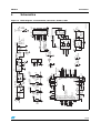
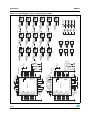
UM0574
User manual
STEVAL-ILL015V1 - LED dimmer demonstration
board based on the STP24DP05 and STM32™
Introduction
This user manual provides instructions for using the STEVAL-ILL015V1 LED dimmer
demonstration board based on the STP24DP05 LED driver and the STM32™
microcontroller accelerated by SPI and DMA. This document provides information including
hardware setup, description of demonstration firmware functionality, PC interconnection
options and evaluation of the STP24DP05 LED driver.
October 2008
Rev 1
1/20
www.st.com
Contents
UM0574
Contents
1
STEVAL-ILL015V1 functional overview . . . . . . . . . . . . . . . . . . . . . . . . . . 5
2
Hardware setup . . . . . . . . . . . . . . . . . . . . . . . . . . . . . . . . . . . . . . . . . . . . . 6
3
2.1
Power supply . . . . . . . . . . . . . . . . . . . . . . . . . . . . . . . . . . . . . . . . . . . . . . . 6
2.2
Microcontroller JTAG . . . . . . . . . . . . . . . . . . . . . . . . . . . . . . . . . . . . . . . . . 6
2.3
Microcontroller clock, reset and USB clock . . . . . . . . . . . . . . . . . . . . . . . . 6
2.4
Error Flag and Temperature Flag signals . . . . . . . . . . . . . . . . . . . . . . . . . . 6
2.5
Jumpers for LED failure simulation . . . . . . . . . . . . . . . . . . . . . . . . . . . . . . . 7
Demonstration firmware functionality description . . . . . . . . . . . . . . . . 8
3.1
Mode "A" - Color Tetris . . . . . . . . . . . . . . . . . . . . . . . . . . . . . . . . . . . . . . . . 9
3.2
Mode "B" - Wave color demonstration . . . . . . . . . . . . . . . . . . . . . . . . . . . . 9
3.3
Mode "C" - Solid color demonstration . . . . . . . . . . . . . . . . . . . . . . . . . . . . 9
3.4
Mode "D" - Error detection (DM) . . . . . . . . . . . . . . . . . . . . . . . . . . . . . . . . 9
3.5
Mode "E" - Error detection (LE + OE) . . . . . . . . . . . . . . . . . . . . . . . . . . . 10
4
PC and software interconnection . . . . . . . . . . . . . . . . . . . . . . . . . . . . . 11
5
Schematics . . . . . . . . . . . . . . . . . . . . . . . . . . . . . . . . . . . . . . . . . . . . . . . 15
6
Bill of materials . . . . . . . . . . . . . . . . . . . . . . . . . . . . . . . . . . . . . . . . . . . . 17
7
Revision history . . . . . . . . . . . . . . . . . . . . . . . . . . . . . . . . . . . . . . . . . . . 19
2/20
UM0574
List of tables
List of tables
Table 1.
Table 2.
Bill of materials . . . . . . . . . . . . . . . . . . . . . . . . . . . . . . . . . . . . . . . . . . . . . . . . . . . . . . . . . . 17
Document revision history . . . . . . . . . . . . . . . . . . . . . . . . . . . . . . . . . . . . . . . . . . . . . . . . . 19
3/20
List of figures
UM0574
List of figures
Figure 1.
Figure 2.
Figure 3.
Figure 4.
Figure 5.
Figure 6.
Figure 7.
Figure 8.
Figure 9.
Figure 10.
Figure 11.
Figure 12.
Figure 13.
Figure 14.
4/20
STM32™ Cortex™ . . . . . . . . . . . . . . . . . . . . . . . . . . . . . . . . . . . . . . . . . . . . . . . . . . . . . . . . 5
STEVAL-ILL015V1 demonstration board layout . . . . . . . . . . . . . . . . . . . . . . . . . . . . . . . . . . 6
The letter "A" indicates the first menu item . . . . . . . . . . . . . . . . . . . . . . . . . . . . . . . . . . . . . . 8
Demonstration board controls. . . . . . . . . . . . . . . . . . . . . . . . . . . . . . . . . . . . . . . . . . . . . . . . 8
Moving the jumper from P21 to P2 results in detection of two defective LEDs. . . . . . . . . . 10
Software - MS Windows® . . . . . . . . . . . . . . . . . . . . . . . . . . . . . . . . . . . . . . . . . . . . . . . . . . 11
The USB host (PC) detection in progress. . . . . . . . . . . . . . . . . . . . . . . . . . . . . . . . . . . . . . 11
The USB host (PC) detected . . . . . . . . . . . . . . . . . . . . . . . . . . . . . . . . . . . . . . . . . . . . . . . 12
The USB host (PC) not found . . . . . . . . . . . . . . . . . . . . . . . . . . . . . . . . . . . . . . . . . . . . . . . 12
Manual board connection . . . . . . . . . . . . . . . . . . . . . . . . . . . . . . . . . . . . . . . . . . . . . . . . . . 13
Board connected successfully . . . . . . . . . . . . . . . . . . . . . . . . . . . . . . . . . . . . . . . . . . . . . . 13
Error detection mode performed . . . . . . . . . . . . . . . . . . . . . . . . . . . . . . . . . . . . . . . . . . . . . 14
Block diagram - microcontroller, connectors, buttons, USB . . . . . . . . . . . . . . . . . . . . . . . . 15
Block diagram - drivers, high-brightness LEDs. . . . . . . . . . . . . . . . . . . . . . . . . . . . . . . . . . 16
UM0574
1
STEVAL-ILL015V1 functional overview
STEVAL-ILL015V1 functional overview
STEVAL-ILL015V1 demonstration board features:
●
Two STP24DP05 (TQFP48) for connection of 16 RGB LEDs
●
16 RGB high-brightness LEDs
●
STM32 microcontroller using internal HS oscillator
●
High-efficiency switching DC-DC power supply using the ST1S010
●
DC power supply 7.5 - 18 V (undifferentiated polarity, over voltage protection)
●
DC input current 0.7 A max., standard supply connector
●
LED current regulation
●
Controlled by 3 buttons, a knob and a reset/back button
●
Available test point for each important signal
●
JTAG interface for microcontroller firmware change/update
●
Error and over temperature LEDs for each LED driver.
●
3 jumpers allowing disconnection of 3 LEDs from the driver for testing the error
detection mode
●
3 jumpers allowing shorting of 3 LEDs from the driver for testing the error detection
mode
●
Mini USB connector for PC interconnection
Figure 1.
STM32™ Cortex™
The board is distributed with firmware which enables standalone and non standalone
demonstration. Features include:
●
LED diagnostic
●
Adjustable brightness and color of each individual LED
●
Animated text
●
GUI (graphical user interface) software for LED diagnostics (see Figure 6)
5/20
Hardware setup
2
UM0574
Hardware setup
Figure 2 shows the component description and layout of the STEVAL-ILL015V1
demonstration board.
Figure 2.
2.1
STEVAL-ILL015V1 demonstration board layout
Power supply
The demonstration board can be supplied by a DC voltage from 7.5 V to 18 V. The power
source must deliver a current of 0.7 A. Since the board features a built-in diode bridge, the
polarity of the input voltage is not specified.
2.2
Microcontroller JTAG
The STM32 on-board microcontroller can be programmed and debugged using the standard
JTAG 20-pin connector included on the board.
2.3
Microcontroller clock, reset and USB clock
The STM32 microcontroller uses its internal RC oscillator to generate an 8 MHz clock (after
PLL is converted to 48 MHz). The clock is used to drive the USB also. Since the internal RC
oscillator does not guarantee clock stability, which is defined in the USB specification, we do
not recommend using the internal oscillator together with USB functionality. The USB is
used in this case only for demonstration purposes, but performance is limited due to internal
RC oscillator stability issues.
2.4
Error Flag and Temperature Flag signals
Each LED driver has one pin dedicated to an Error Flag (EF) signal and Temperature Flag
(TF) signal. Both signals can directly drive an LED. The LEDs are assembled on the board
and the driver status can be easily checked.
6/20
UM0574
Hardware setup
The EF indicates the condition of the driven LEDs. If any of them is found to be defective,
error detection mode is activated and the EF LED turns on.
The TF indicates the thermal condition of the LED driver. If the temperature exceeds the
maximal allowed temperature, the driver automatically switches off its outputs. The TF LED
shines over the whole period while the driver outputs are switched off due to the over
temperature.
2.5
Jumpers for LED failure simulation
Some LED defects can be simulated. The removal of jumper P20, P21 and P22 causes
open circuits of the D1-green, D2-green and D3-green LEDs, respectively. The attachment
of the jumper to position P1, P2 and P3 causes a short-circuit of the D6-blue, D9-blue and
D12-blue LEDs.
These simulated defects can be detected during activation of the error detection mode (see
Chapter 3, which describes the firmware modes). The defective LED is indicated by
switching of the corresponding red LED.
7/20
Demonstration firmware functionality description
3
UM0574
Demonstration firmware functionality description
Main features of the firmware:
●
Demonstrate brightness control for each LED separately
●
Demonstrate color control for each LED separately
●
Perform error detection to detect LED failure
●
Provide a simple game simulation
A menu displayed on the RGB LEDs after powering up the board. The menu items are
depicted as the letters "A", "B", "C", "D" and "E", as shown in Figure 3. After power up, the
letter "A" - the first item on the RGB LED array - begins blinking. Pressing the buttons
changes the display to the next successive letter, to permit the selection of the desired menu
item.
Figure 3.
The letter "A" indicates the first menu item
The board can be controlled by four buttons and one knob, as shown in Figure 4:
●
Back/reset button (S4) - exits from current task and returns to the main menu
●
Left button (S1) - changes the menu item in descending order
●
Center button (S2) - selects the displayed menu item
●
Right button (S3) - changes the menu item in ascending order
●
Knob (R17 potentiometer) - changes the color of the menu display from blue to red
Figure 4.
8/20
Demonstration board controls
UM0574
Demonstration firmware functionality description
The firmware mode menu items:
3.1
●
Mode "A" - Color Tetris
●
Mode "B" - Wave color demonstration
●
Mode "C" - Solid color demonstration
●
Mode "D" - Error detection (DM)
●
Mode "E" - Error detection LE + OE (Feature may not be available for all firmware
releases).
Mode "A" - Color Tetris
Mode "A" is a simple game similar to Tetris. The game begins with a green “brick” moving
from the bottom to the top of the LED display. The X-axis position of the brick can be
controlled using the left and right buttons. Once the brick reaches the top of an LED area
occupied by another settled brick, it settles also and its color changes to blue. Once the
brick becomes blue, it cannot be moved. When a full row of blue bricks is completed, the row
disappears and the player is awarded points. The game ends when the blue bricks reach the
bottom of the LED area. When the game is over, the points obtained are shown. Pressing
the center button starts new game. The knob changes the light intensity of the LEDs.
3.2
Mode "B" - Wave color demonstration
Mode "B" demonstrates various color effects. The effect changes automatically after a few
cycles of a given effect. The effect can also be changed manually using the center button.
The knob changes the speed of the effect.
3.3
Mode "C" - Solid color demonstration
Mode "C" allows the display of a single color on all of the LEDs. Pressing of the right button
changes the colors in the following order: red, green, blue, yellow (red + green), cyan (green
+ blue), magenta (red + blue), white (red + green + blue) and black (all LEDs off). The left
button changes the colors in the reverse order. The knob changes the light intensity of the
LEDs.
3.4
Mode "D" - Error detection (DM)
Mode "D" performs and displays the detection of faulty LEDs. Every two seconds, an error
detection is performed by the LED drivers. If any defective LEDs are detected, they can be
identified by red light on the corresponding LED diode position. By opening P20, P21 and
P22, an open circuit can be created (LED defective by disconnection) to simulate a defect of
the D1-green, D2-green and D3-green LEDs, as shown in Figure 5. By closing P1, P2 and
P3, a short-circuit is created (LED defective by shorting) to simulate a defect of the D6-blue,
D9-blue and D12-blue LEDs. Entering the diagnostic mode is done using the DM signal.
9/20
Demonstration firmware functionality description
Figure 5.
3.5
UM0574
Moving the jumper from P21 to P2 results in detection of two defective
LEDs
Mode "E" - Error detection (LE + OE)
Mode "E" (which may not be available in some firmware releases) demonstrates the same
functionality as the mode "D", but entering the diagnostic mode is done using LE + OE
signals.
10/20
UM0574
4
PC and software interconnection
PC and software interconnection
Figure 6.
Software - MS Windows®
In order for the software to run correctly, the following steps must be performed:
1.
Disconnect the power supply from the board
2.
Connect the board to the computer using the USB cable
3.
Connect the board to the power supply
4.
If Windows requests the installation of an appropriate driver, use the driver supplied by
ST, VirtualCOMPort
Figure 7.
The USB host (PC) detection in progress
11/20
PC and software interconnection
12/20
Figure 8.
The USB host (PC) detected
Figure 9.
The USB host (PC) not found
UM0574
5.
Run the SWforDimmer.exe application on the computer
6.
If the board is not detected automatically, press the button "Find board on COM port" as
shown in Figure 10.
UM0574
PC and software interconnection
Figure 10. Manual board connection
If the board is found and connected successfully, a green label is displayed on the
application as shown in Figure 11.
Figure 11. Board connected successfully
To perform error detection, click on "Perform error detection". Error detection is performed
correctly and does not depend on the mode to which the board is set.
13/20
PC and software interconnection
UM0574
Figure 12. Error detection mode performed
The evaluation of the error detection over USB:
14/20
1.
If the jumpers P20, P21 and P22 are closed and the jumpers P1, P2 and P3 are open,
no defective LED should be reported by the application graphically after pressing the
button "Perform error detection". See Figure 12.
2.
Moving the jumper from P21 to P2 should result in the indication of a simulated
defective green LED in the first row and the second column and a simulated defective
blue LED in the third row and the third column.
3.
Exit the application and disconnect the board before testing another.
C10
100 nF
RESET/EXIT
S4
R47
100 Ω
S1
C11
100 nF
LEFT
3
CENTER
S2
C12
100 nF
R48
100 Ω
PC14
4 D17
BridgeLH
2
RIGHT
S3
3.3 V
1
2
USRX 1
USTX 2
USDIR 3
U4
C1
6 VIN_SW ST1S10 SW 7
L1 2.2 µH
4.7 µF
2 EN
Ceramic
SYNC PGND
3
R18
(C, D, E)
1 VIN_A
AGND
FB
5.6 kΩ
10
25 V
9 5 4 8 ST 1S
C3
100 nF
R19
1.2 kΩ
PC15
R22
R23
R20
C2
470 nF
1
JTRST
3
JTDI
5
JTMS
7
JTCK
9
10 KΩ JRTCK
11
JTDO
13
JRST
15
10 KΩ DBGRQ
17
10 KΩ DBGACK
19
2
4
6
8
10
12
14
16
18
20
2
3.3 V
R16
2.2 kΩ
LD5
1 Red
2.0 V
3.3 V
3.3 V CN1
C4
100 µF (47 µF)
Tantal
(C, D, E)
16 V (10 V)
4.5 V
AM00209
3.3 V
3 R17
JTRST
GM : MLW20G
R15
ADC
2 VarRez
JTDO
USDIR
3.3 V
1 10 KΩ
JTDI
USTX
330
C13
C5 4.7 nF
100 nF
JTCK
USRX
R25 10 KΩ
48 47 46 45 44 43 42 41 40 39 38 37
USB1
PB9 PB8 BOOT0 PB7 PB5 PB3PA15 U3
VSS_3
STM32Fx103C
SHLD
5
PB6 PB 4
VDD_ 3
PA14
3.3 V
U6
1 VBAT
VDD_2 36
4 GND
PC13 2 PC13
VSS_2 35
1.5 kΩ VCC
3 D+
34
JTMS
PC14 3 PC14
PA13
2 D–
6
USBDP 1 D1 33 R
STM32
D4
33
USBDP
PC15 4 PC15
PA12
1 VBUS
3.3
V
EXTCLK 5 PD0_O -I SC N
PA11 32 USBDN
2 GND
5
V
440247-2
31
CC
JRST 6 PD1_OSC-OUT
PA10
USBDN 3 D2 33 R
PA9 30
JTRST 7 NRST
D3 4
PA8 29 CLKOUT
8 VSSA
USB_ESD
PB15 28
3.3 V 9 VDDA
PB14 27
10 PA0- WKUP
PB13 26 OE1B
11 PA1
LF33xDT U5
4.5 V
3.3 V
PB11 PB12 25 OE2B
3.3 V
3.3 V
1 V
12 PA2
VOUT 5
V
IN
C8
C7
DD_1
PA5 PA7
PB2
C16
C17
10 µF
2
10 nF
PA3 PA4 PA6 PB0 PB1 PB10 VSS_1
100 nF
100 nF
GND
4
NC
22 23 24
19 20 21
13 14 15 16 17 18
3 INHIBIT
16 V (10 V)
ADC LE
OE2G DM
SDI
3.3 V
Tantal (A)
CLK SDO OE2R OE1R
OE1G
C14
100 nF
R46
100 Ω
PC13
1
ST: SM6T33A
5
JRST
1
2
3
GM:K375A D18
CN5
UM0574
Schematics
Schematics
Figure 13. Block diagram - microcontroller, connectors, buttons, USB
15/20
16/20
EF1
SDOI
OE1R
OE1G
OE1B
3.3 V
C9
100 nF
R7
AA
4.5 V
D2
CR CR
D21 R35
27 Ω D22CCG CG
D23 CB CB
A A
4.5 V
D3
D31 R40
CR CR
27 Ω D32CCG CG
D33 CB CB
AA
4.5 V
RGBLED
RGBLED
RGBLED
4.5 V
4.5 V
4.5 V
D4
D5
D6
D61 R41
CR CR
D41 R31
CR CR
CR CR
D51 R36
A
A
D62
D52
D42
CG
CG
CG
27 Ω
CG A
CG A
CG A A
27 Ω
27 Ω
D63 CB CB
D43 CB CB
D53 CB CB
D1
CR CR
D11 R30
27 Ω D12CCG CG
D13 CB CB
RGBLED
RGBLED
RGBLED
4.5 V
4.5 V
4.5 V
D7
D8
D9
R42
D91
CR
D81 R37
CR CR
D71 R32
CR CR
R6
CR
27 Ω D92 CG CG A A
R5
27 Ω D72 CG CG A A
27 Ω D82 CG CG A A
D83 CB CB
D93 CB CB
D73 CB CB
1 kΩ 91 0 Ω
1 kΩ
RGBLED
RGBLED
RGBLED
4.5 V
4.5 V
4.5 V
D10
D11
D12
D121 R43
CR
D111 R38
D101 R33
CR CR
CR CR
CR
27 Ω D102 CG CG A A
27 Ω D122 CG CG A A
27 Ω D112CG CG A A
D123 CB CB
D113CB CB
D103 CB CB
3.3 V
U1
STP24DP05
AM00210
RGBLED
RGBLED
RGBLED
4.5 V
D13 4.5 V
D14
D15
4.5 V
D161
D151 D143 D133
D151 R44
D141 R39
D131 R34
CR CR
CR CR
CR CR
D162
D132
D142
D152
A
A
27 Ω D152 CG CG A A
27 Ω D132 CG CG A
27 Ω D142CG CG A
D163
D153
D141
D131
D153 CB CB
D143CB CB
D133 CB CB
48 47 46 45 44 43 42 41 40 39 38 37 U2
RGBLED
RGBLED
RGBLED
STP24DP05
B8 G8 R8 B7 G7 R7 B6 G6 R6 B5 G5 R5
4.5 V
1 GND
D16
GND 36
3.3 V
CR CR
D161 R45
35
SDOI 2 SDI
SDO
SDO
LE
3 LE /DM
27 Ω D162 CG CG A A
C15
OE- R/DM 34 OE2R
D163 CB CB
CLK 4 CLK
33
OE2G
100
nF
OE- G
OE2B
P1
DM
5 DM
32
P20
RGBLED
OE- B
D63
3.3 V 6 V
D12C 1
1
VDD 31 3.3 V
DD
4.5 V 2
D12
STP24
30
7 GND
2
GND
TF 2 8 TF
3.3 V
Header2
Header2
yellow
DG 29 EF2
LD1
P2
EF 2 9 EF
R1
P21
1
2 TF1
RE XTR 28
D93
3.3 V 10 DF0
D22C 1
1
RE XTG 27
2.2 kΩ
orange
4.5 V 2
R10
LD2
3.3 V 11 DF1
D22
2
RE XTB 26
R2
R9
1
2 EF1
25
12 GND
GND
Header2
R8
910 Ω
Header2
2.2 kΩ
yellow
1 kΩ
LD3
P3
P22
R1G1 B1 R2 G2 B2 R3 G3 B3 R4 G4 B4
R3
1
2 TF2
D123 1
1 kΩ
D32C 1
4.5 V 2
2.2 kΩ
D32
13 14 15 16 17 18 19 20 21 22 23 24
2
orange
LD4
R4
D101
D113
D91
D123
1
2 EF2
Header2
Header2
D102
D122
D92
D112
2.2 kΩ
D103
D93
D121
D111
13 14 15 16 17 18 19 20 21 22 23 24
D11 D12
D42 D43
D13 D21 D23 D31 D33 D41
D22
D32
R1G1 B1 R2 G2 B2 R3 G3 B3 R4 G4 B4
D62
D72
D81 D73 D71D63 D61D53
D52 D51
D83 D82
48 47 46 45 44 43 42 41 40 39 38 37
B8 G8 R8 B7 G7R7 B6 G6 R6 B5 G5 R5
1 GND
GND 36
2 SDI
SDI
SDO 35
LE
3 LE/DM
OE- R/DM 34
4 CLK
CLK
OE- G 33
5 DM
DM
OE- B 32
3.3 V 6 V
VDD 31
DD
STP24
30
7 GND
GND
8 TF
TF1
DG 29
EF1
9 EF
REXTR 28
3.3 V 10 DF0
REXTG 27
3.3 V 11 DF1
REXTB 26
12 GND
GND 25
Schematics
UM0574
Figure 14. Block diagram - drivers, high-brightness LEDs
UM0574
Bill of materials
6
Bill of materials
Table 1.
Bill of materials
Designator
Comment
Description
Footprint
C1
4.7 µF (10 µF)
Ceramic capacitor 25 / 35 V
1812LH
C2
470 nF
Capacitor
0805
C3
100 nF
Capacitor
0805
C4
100 µF (47 µF) size D, 16 V Tantal capacitor - polarized
7343_LH
C5
4.7 nF
Capacitor
0805
C7
10 µF size A 16 V (10 V)
Tantal capacitor - polarized
3528_ABLH
C8
10 nF
Capacitor
0805
C9 -C17
100 nF
Capacitor
0805
CN1
GM: MLW20G
Header 10X2, JTAG, 10 pin, dual row
HDR2X10keyLH
CN5
GM: K375A
Input power, 4.4 V-36 V
DC10B
D1 - D16
RGBLED
LATB_T686
TOPLED
D17
BridgeLH
Full wave diode bridge
GMBridgeBig
D18
ST:SM6T33A
SMA
DDD1
ST_LOGO
ST LOGO
DDD2
ROH1
ROH1
DDD3
ROH2
ROH2
Hole1 - hole4
Distance hole
J1
440247-2
USB 2.0, right angle, SMT, B type, receptacle, 5
position, black
440247LH
L1
3.3 µH
Inductor
inductor332
LD1
Yellow
Typical yellow, orange GaAs LED
D0805LH
LD2
Yellow
Typical yellow, orange GaAs LED
D0805LH
LD3
Yellow
Typical yellow, orange GaAs LED
D0805LH
LD4
Yellow
Typical yellow, orange GaAs LED
D0805LH
LD5
Red
Typical red/amber GaAs LED
D0805LH
P1
Header 2
Header, 2-pin
HDR1X2
P2
Header 2
Header, 2-pin
HDR1X2
P3
Header 2
Header, 2-pin
HDR1X2
P4
Signal for serial
Header, 3-pin
HDR1X3
P5
Power for serial
Header, 2-pin
HDR1X2
P20
Header 2
Header, 2-pin
HDR1X2
P21
Header 2
Header, 2-pin
HDR1X2
P22
Header 2
Header, 2-pin
HDR1X2
17/20
Bill of materials
Table 1.
UM0574
Bill of materials (continued)
Designator
Comment
Description
Footprint
R1 - R4
2.2 kΩ
0805
R5
1 kΩ
0805
R6
1 kΩ
0805
R7
750 Ω
0805
R8
1 kΩ
0805
R9
1 kΩ
0805
R10
750 Ω
0805
R15
330 Ω
Resistor
0805
R16
2.2 kΩ
Resistor
0805
R17
10 kΩ
Potentiometer
VR5
R18
5.6 kΩ
Resistor
0805
R19
1.2 kΩ
Resistor
0805
R20
10 KΩ
0805
R22
10 KΩ
0805
R23
10 KΩ
0805
R25
100 KΩ
0805
R30 - R45
27 Ω
0603LH
R46
100 Ω
Resistor
0805
R47
100 Ω
Resistor
0805
R48
100 Ω
Resistor
0805
S1
LEFT
Switch
Button_double
S2
CENTER
Switch
Button_double
S3
RIGHT
Switch
Button_double
S4
RESET/EXIT
Small switch
Button_DT2112C
U1
STP24DP05
LED driver 24-channel
U2
STP24DP05
LED driver 24-channel
U3
STM32F103Cx
Microcontroller Cortex
U4
ST1S10
ST1S10
DFN8cool4LH
U5
LF33xDT
Linear voltage stabilizer
SOT23-5L
U6
USB_ESD
USB signal over voltage protection
SOT666IP
18/20
UM0574
7
Revision history
Revision history
Table 2.
Document revision history
Date
Revision
10-Oct-2008
1
Changes
Initial release.
19/20
UM0574
Please Read Carefully:
Information in this document is provided solely in connection with ST products. STMicroelectronics NV and its subsidiaries (“ST”) reserve the
right to make changes, corrections, modifications or improvements, to this document, and the products and services described herein at any
time, without notice.
All ST products are sold pursuant to ST’s terms and conditions of sale.
Purchasers are solely responsible for the choice, selection and use of the ST products and services described herein, and ST assumes no
liability whatsoever relating to the choice, selection or use of the ST products and services described herein.
No license, express or implied, by estoppel or otherwise, to any intellectual property rights is granted under this document. If any part of this
document refers to any third party products or services it shall not be deemed a license grant by ST for the use of such third party products
or services, or any intellectual property contained therein or considered as a warranty covering the use in any manner whatsoever of such
third party products or services or any intellectual property contained therein.
UNLESS OTHERWISE SET FORTH IN ST’S TERMS AND CONDITIONS OF SALE ST DISCLAIMS ANY EXPRESS OR IMPLIED
WARRANTY WITH RESPECT TO THE USE AND/OR SALE OF ST PRODUCTS INCLUDING WITHOUT LIMITATION IMPLIED
WARRANTIES OF MERCHANTABILITY, FITNESS FOR A PARTICULAR PURPOSE (AND THEIR EQUIVALENTS UNDER THE LAWS
OF ANY JURISDICTION), OR INFRINGEMENT OF ANY PATENT, COPYRIGHT OR OTHER INTELLECTUAL PROPERTY RIGHT.
UNLESS EXPRESSLY APPROVED IN WRITING BY AN AUTHORIZED ST REPRESENTATIVE, ST PRODUCTS ARE NOT
RECOMMENDED, AUTHORIZED OR WARRANTED FOR USE IN MILITARY, AIR CRAFT, SPACE, LIFE SAVING, OR LIFE SUSTAINING
APPLICATIONS, NOR IN PRODUCTS OR SYSTEMS WHERE FAILURE OR MALFUNCTION MAY RESULT IN PERSONAL INJURY,
DEATH, OR SEVERE PROPERTY OR ENVIRONMENTAL DAMAGE. ST PRODUCTS WHICH ARE NOT SPECIFIED AS "AUTOMOTIVE
GRADE" MAY ONLY BE USED IN AUTOMOTIVE APPLICATIONS AT USER’S OWN RISK.
Resale of ST products with provisions different from the statements and/or technical features set forth in this document shall immediately void
any warranty granted by ST for the ST product or service described herein and shall not create or extend in any manner whatsoever, any
liability of ST.
ST and the ST logo are trademarks or registered trademarks of ST in various countries.
Information in this document supersedes and replaces all information previously supplied.
The ST logo is a registered trademark of STMicroelectronics. All other names are the property of their respective owners.
© 2008 STMicroelectronics - All rights reserved
STMicroelectronics group of companies
Australia - Belgium - Brazil - Canada - China - Czech Republic - Finland - France - Germany - Hong Kong - India - Israel - Italy - Japan Malaysia - Malta - Morocco - Singapore - Spain - Sweden - Switzerland - United Kingdom - United States of America
www.st.com
20/20