1
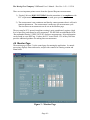
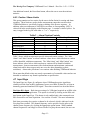
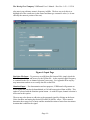
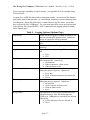
The Moving Pixel Company VSBDemod User’s Manual – Doc. Rev. 1.02 -- 1/25/10 VSBDemod User’s Manual - Page i - The Moving Pixel Company VSBDemod User’s Manual – Doc. Rev. 1.02 -- 1/25/10 Table of Contents 1 Overview..........................................................................................................................iv 1.1 Description...............................................................................................................iv 1.2 Terms and Definitions............................................................................................iv 1.3 Contacting The Moving Pixel Company................................................................v 2 VSBDemod Installation...................................................................................................1 2.1 Installation Via CD ROM......................................................................................1 2.2 Installation Via Website.........................................................................................1 2.3 Licensing and License Keys....................................................................................2 3 Setting up the RSA...........................................................................................................3 3.1 Enabling the RSA Application for Remote Control.............................................3 3.2 Enabling the VXI-11 Server....................................................................................3 3.3 Improving RSA Color Resolution..........................................................................3 3.4 Updating Visa Devices.............................................................................................3 4 Operation.........................................................................................................................5 4.1 Quick Start...............................................................................................................5 4.1.1 Simulated Acquisition.........................................................................................5 4.1.2 Real Acquisition..................................................................................................6 4.2 Connection Dialog....................................................................................................6 4.3 Register Dialog.........................................................................................................7 4.3.1 RSA Processing License.....................................................................................7 4.3.2 File Processing License.......................................................................................8 4.4 Pilot Refinement.......................................................................................................9 4.5 Spectrum Emission Mask (SEM) Test...................................................................9 4.6 Monitor Page..........................................................................................................10 4.6.1 Process Control and Status................................................................................11 4.6.2 Measurement Results........................................................................................12 4.6.3 Caution / Alarm Limits.....................................................................................13 4.7 Input Page...............................................................................................................13 4.8 Options Page...........................................................................................................15 4.8.1 General Options................................................................................................15 4.8.2 Spectrum Emission Mask Test Options............................................................16 4.8.3 Logging Options...............................................................................................16 4.9 Spectrum Page........................................................................................................18 4.10 Baseband Page......................................................................................................18 - Page ii - The Moving Pixel Company VSBDemod User’s Manual – Doc. Rev. 1.02 -- 1/25/10 4.11 Eye Page................................................................................................................19 4.12 Constellation Page................................................................................................20 4.13 Frequency Response Page...................................................................................21 5 Measurement Overview.................................................................................................23 5.1 Signal-to-Noise (S/N)..............................................................................................23 5.2 Error Vector Magnitude (EVM)..........................................................................23 5.3 Complex Modulation Error Ratio (MER)...........................................................24 5.4 Pilot Amplitude Deviation.....................................................................................24 5.5 Peak/Average Power..............................................................................................24 5.6 Frequency Response (Peak-to-Peak)....................................................................25 5.7 Group Delay (Peak-to-Peak).................................................................................25 6 Menus.............................................................................................................................26 7 Troubleshooting.............................................................................................................27 8 Appendix A – Measurement Specifications..................................................................28 9 Appendix B – Generating RSA IQ Data Files..............................................................29 10 Appendix C – SEM File Example...............................................................................30 11 Appendix D – Log File Example.................................................................................31 12 Software License Agreement.......................................................................................34 - Page iii - The Moving Pixel Company VSBDemod User’s Manual – Doc. Rev. 1.02 -- 1/25/10 1 Overview 1.1 Description VSBDemod is a Windows software application that performs automated measurements on 8VSB digital television signals modulated with the ATSC Digital Television Standard. The application works in conjunction with a Tektronix spectrum analyzer (e.g. an RSA3303B) to acquire signals at the transmitter. Software then demodulates the acquired RF signal data to obtain base-band symbol waveforms, performing quantitative analysis and computing the following measurements: • • • • • • • Signal to Noise Ratio Complex Modulation Error Ratio Error Vector Magnitude Pilot Amplitude Deviation Frequency Response (Peak-to-Peak) Group Delay (Peak-to-Peak) Spectrum Emission Mask measurement (on the RSA) The following graphs are also displayed: • • • • • Spectrum of Acquired Data Recovered I, Regenerated (Ideal) I, Symbols Eye Diagram Constellation Diagram Frequency Error & Group Delay Response Signal measurements can be automated to run continuously or periodically, thereby monitoring transmitter performance on a constant basis. Time-stamped measurements can be logged in text files for result record keeping. Please refer to subsequent chapters for detailed information on VSBDemod operation and its measurements. The VSBDemod software may be downloaded from our website (http://www.movingpixel.com/main.pl?VSBDemod.html) and installed for free. Unlicensed operation provides for the simulated acquisition of data for demonstration purposes. Licensed operation requires keys acquired from TMPC to process real VSB signals, either via direct connection to an RSA or from a saved IQ data file from an RSA. 1.2 Terms and Definitions The following terms and definitions are used in this manual: TMPC RSA The Moving Pixel Company Real-time Spectrum Analyzer (e.g. RSA3303B, RSA3308B, RSA3408B, etc) - Page iv - The Moving Pixel Company VSBDemod User’s Manual – Doc. Rev. 1.02 -- 1/25/10 SEM S/N MER EVM 1.3 Spectrum Emission Mask Signal-to-noise Modulation Error Ratio Error Vector Magnitude Contacting The Moving Pixel Company Phone +1.503.626.9663 US Pacific Time Zone Fax +1.503.626.9653 US Pacific Time Zone Address The Moving Pixel Company 4905 SW Griffith Drive, Suite 106 Beaverton, Oregon 97005 USA Email [email protected] Web site http://www.movingpixel.com Documentation http://www.movingpixel.com/main.pl?VSBDemod.html - Page v - The Moving Pixel Company VSBDemod User’s Manual – Doc. Rev. 1.02 -- 1/25/10 2 VSBDemod Installation The VSBDemod application can be installed on a Windows computer running XP or Vista. In particular, you can install it on your RSA or a separate desktop/laptop computer connected to the same network as your RSA. The computer on which VSBDemod is installed and run will be referred to as the host computer (which may or may not be the RSA). Real-time operation requires communication with the RSA and makes use of Tektronix’ TekVisa software, which must be installed on both the host computer and RSA. Also, VSBDemod requires the Microsoft .NET Framework 3.5 to be installed on the host computer. Installation of each of these components is described below. Note that VSBDemod can operate in an offline mode that does not require connection to an RSA. In this mode, the application can demonstrate all of its capabilities by simulating acquisition of a VSB signal or, if licensed, by reading in a saved IQ data file from an RSA. Operating in offline mode does not require that TekVisa be installed. 2.1 Installation Via CD ROM If you received an application CD ROM, all the components you need should be on it. 1. Run the Setup.exe provided on the host computer, which by default installs the application in the directory: C:\Program Files\TMPC\VSBDemod. In addition, if .NET 3.5 or its precursors are not present, they will be installed as well. 2. Check if TekVisa 3.3 (or greater) is installed on the host computer: • Click on Start->Settings->Control Panel • Click on Add or Remove Programs • Scroll to see if “OpenChoice TekVISA” is installed • Click on “Click here for support information” to see the version • Verify that it is version 3.3 or above 3. If not, run the TekVisa installation program provided on the CD ROM : TekVISA_3.3.2.7_2009.01.29.17.07.38_14810_EN.exe or download the latest version from the Tektronix website. 4. If TekVisa version 3.3 (or greater) is not already installed on the RSA, run the TekVisa installation program provided on the CD ROM: TekVISA_3.3.2.7_2009.01.29.17.07.38_14810_EN.exe 2.2 Installation Via Website If you downloaded the VSBDemod installation program from the Moving Pixel Company website, you may need to download .NET 3.5 from Microsoft and TekVisa from Tektronix. 1. Check if .NET 3.5 is installed on the host computer: • Click on Start->Settings->Control Panel • Click on Add or Remove Programs - Page 1 - The Moving Pixel Company VSBDemod User’s Manual – Doc. Rev. 1.02 -- 1/25/10 • Scroll to see if “Microsoft .NET Framework 3.5” is installed 2. If not, download and install .NET 3.5 from the Microsoft website: http://download.microsoft.com/download/6/0/f/60fc5854-3cb8-4892-b6dbbd4f42510f28/dotnetfx35.exe Please note that it is over 200 MB! 3. Check if TekVisa 3.3 is installed on the host computer: • Click on Start->Settings->Control Panel • Click on Add or Remove Programs • Scroll to see if “OpenChoice TekVISA” is installed • Click on “Click here for support information” to see the version • Verify that it is version 3.3 or above 4. If not, download and install the latest TekVisa from the Tektronix website: http://www2.tek.com/cmswpt/swdownload.lotr? ct=SW&cs=sut&ci=15592&lc=EN 5. Check if TekVisa 3.3 is installed on the RSA (if different from host computer). 6. If not, install it on the RSA 2.3 Licensing and License Keys VSBDemod requires licensing keys to enable certain functionality in the application. Keys are stored in the TMPCLicense.txt file of the application directory, managed using the VSB application itself (using the Help->Register… dialog). Keys may or may not have an expiration date, potentially enabling function for a limited amount of time. Two types of license keys are used: RSA Processing Key – required to control an RSA for real-time acquisition, measurement and logging of signal data. A unique RSA processing key enables use of VSBDemod with a specific RSA. This type of key is always obtained from TMPC with purchase of a license. As detailed further in the Register dialog description (see section 4.2), to obtain a key specific to a particular RSA, customers email a specific RSA Processing Request Code to TMPC and an RSA Processing Key is returned via email and added to the license file. File Processing Key – required to analyze saved I/Q data files from an RSA. A unique file processing key enables a specific host computer to process RSA files. This type of key can be obtained from TMPC or generated by customers who have a valid RSA Processing Key. As detailed further in the Register dialog description, to obtain a File Processing Key, customers either email a specific File Processing Request Code to TMPC or they make use of the code themselves to generate one for the specific host they want to run the application on for file processing. - Page 2 - The Moving Pixel Company VSBDemod User’s Manual – Doc. Rev. 1.02 -- 1/25/10 3 Setting up the RSA During operation, VSBDemod performs any necessary setup and configuration of the RSA for measurement and acquisition. Specifically, you do not need to set any of the standard parameters on the RSA such as frequency, span, and amplitude for the application to work correctly. Only a few setup details must be handled before we begin. 3.1 Enabling the RSA Application for Remote Control Once both the host and RSA have the prerequisite software, you must enable the RSA for remote control using TekVisa. In the RSA application, perform the following: 1. 2. 3. 4. 5. Push the System button Select Remote Setup… (option 3) Select GPIB Setup… (option 2) Select Connection Mode… (option 2) Select TekVISA (option 2) 3.2 Enabling the VXI-11 Server Next, to enable remote computers to access the RSA application via TekVisa, you must enable the VXI-11 server on the RSA. When TekVisa is installed, an application called the “TekVisa LAN Server” is installed and accessed via an icon in the system tray (far right of the task bar). After installation, the server will be initially disabled and its icon will be overlaid with a red ‘X’. If you right click on the icon, you can enable the VXI-11 server by selecting the appropriate option in the pop-up menu. Note if the VXI-11 server icon is not present in the system tray, you can manually start it via “Start->Programs->TekVISA->VXI-11 Server Control”. Generally, you will want to start the VSI-11 server automatically at power-up. To do this, you can right-click on the TekVisa LAN Server icon, select “Server Properties…” and check “Start server at system powerup”. 3.3 Improving RSA Color Resolution If you plan to run VSBDemod on the RSA, you may want to set the color resolution to 24-bits. The RTSA application, by default, forces the display to 8-bit color mode each time it is run. To disable this, right-click on the RTSA icon, select Properties, Compatibility tab, and uncheck the “Run in 256 colors” checkbox. Then set the display color to 24-bits with Start->Control Panel, Display, Settings Tab, Color Quality = High (24-bit). 3.4 Updating Visa Devices It is important to initialize the Visa device list on the RSA the first time you attempt to establish communication. We recommend you first do this on the RSA (regardless where VSBDemod is to run) since it helps diagnose any connectivity problems. - Page 3 - The Moving Pixel Company VSBDemod User’s Manual – Doc. Rev. 1.02 -- 1/25/10 On the RSA, click on the Visa Resource Manager icon in the system tray (bottom right). This brings up a context menu from which you can start the Instrument Manager. In the Instrument Manager, click on the Update button to refresh the instrument list. Locally, the RSA should appear as GPIB8::1::INSTR. If it does not show up, make sure the RSA application is running and it is enabled for TekVisa communication as described in section 3.1. If it still does not show up, shut down the RSA application and restart it. Next, if you are running VSBDemod on a remote computer, you should bring up the Instrument Manager on the remote host and click the Update button. You should see the instrument name show up which generally includes its TCP/IP address (e.g. TCPIP::192.168.0.22::INSTR). - Page 4 - The Moving Pixel Company VSBDemod User’s Manual – Doc. Rev. 1.02 -- 1/25/10 4 Operation The VSBDemod application is centrally organized around a tab control that occupies most of the application window. Each tab page in the control organizes different settings and options, in particular grouped as follows: • • • • • • • • Monitor Page – provides overall processing and status controls, measurement results, and caution/alarm limit setting. Input Page – sets the method for data acquisition and associated parameters Options Page – sets options for application behavior and logging results Spectrum Page – displays the spectrum of the acquired data Baseband Wfm Page – displays the demodulated I waveform, regenerated I waveform, and symbol sample points Eye Page – displays an eye diagram of the demodulated data Constellation Page – displays an IQ constellation diagram of the demodulated data Freq Resp Page – displays the frequency response and group delay of the demodulated data See subsequent sections for detailed information about each page. 4.1 Quick Start At start-up, the Monitor page is displayed. If the system file from the previous session is found, it is loaded, initializing configuration settings and acquired data. If the system file is not found, only the configuration settings from the previous session are loaded (which are saved in a separate application file). 4.1.1 Simulated Acquisition At initial start-up, application settings are configured to demonstrate the operation of VSBDemod using simulated data as input. To run a single measurement, simply click on the Process button in the Monitor page. While the application generates and processes the simulated data (which takes about 10 seconds), status is displayed describing the current processing task. When processing is done, measurement results are displayed in the Monitor page. To see various graphs of the processed data, click on the associated tab. To change the parameters of the simulation so that Gaussian noise is added to the data, click on the Input page and check the Insert Noise checkbox. If desired, edit the noise S/N and S/N standard deviation. Return to the Monitor page and click the Process button. Repeated processing reveals changing noise levels and measurement results. Next, you can automate processing and record results by selecting the Options page, clicking on the Log Results checkbox, and typing (or browsing) for a directory to store the results file(s). Then, back in the Monitor page, edit the Max Iterations field to 10 and the Meas Delay field to 4 (seconds). Click on the Process button to initiate the process - Page 5 - The Moving Pixel Company VSBDemod User’s Manual – Doc. Rev. 1.02 -- 1/25/10 sequence. VSBDemod will now proceed for 10 iterations, logging results to a text file. The file created has a unique name that starts with “VSBLog” and is followed by the date and time. While measurements are ongoing, you can view graphs results from the last iteration by clicking the desired tab. If a results tab is selected during an ongoing processing sequence, the graph will be updated each iteration. You can also stop processing at any time by clicking on the Process button, whose label is changed during processing to Abort. 4.1.2 Real Acquisition To perform acquisition and analysis of a real signal, VSBDemod must first be connected to the RSA. This is done via the Connect->RSA Connect… menu option (see section 4.2). Once connected, if you haven’t yet done so, you must set up real-time licensing via the Help->Register menu option (see section 4.3). When your RSA is properly licensed, the RSA real-time option button will be enabled in the Input page of the application. Select this option and also select the channel frequency. Then select the Monitor page and click the Process button to begin acquisition and analysis. The first time you initiate processing after connecting to the RSA, a preprocessing step called pilot refinement is performed (see section 4.4). This ensures that the frequency and reference level used for demodulation is very accurate and maximizes the dynamic range of the instrument. After initialization, the Spectrum Emission Mask test is performed (see section 4.5) if enabled in the Options page. Following this test, IQ data is acquired and processing continues as with simulated acquisition, with the demodulation and measurement of the signal data (see previous section). 4.2 Connection Dialog To acquire and process real signal data, VSBDemod must first connect to the RSA. This is done through the Connect->RSA Connect… menu option, which brings up the Connection Dialog (see Figure 1). Figure 1 – Connection Dialog - Page 6 - The Moving Pixel Company VSBDemod User’s Manual – Doc. Rev. 1.02 -- 1/25/10 When first displayed, the Connection Dialog fills in the RSA hostname drop-down control with devices visible through TekVisa. If your RSA is not listed, you can click the Scan button to rescan for devices after diagnosing the problem. Choose the desired RSA and click the Connect button to select the instrument and close the dialog. The currently connected RSA (or Offline for no connection) will be displayed in the main window status bar (second pane). 4.3 Register Dialog As described in section 2.3, an RSA Processing Key is required for each RSA to be controlled for real-time data acquisition and measurement. To enable VSBDemod for real-time RSA control, first connect to the RSA via the Connect->RSA Connect… menu option. Then bring up the Register dialog via the Help->Register… menu option (see Figure 2). Follow the procedures outlined in this section to add licenses to the application’s license file. Click on the Review Keys button to display current processing keys and their expiration status. When finished, click the Done button. 4.3.1 RSA Processing License When connected to an RSA, the RSA Processing Request Code field will be filled in (otherwise, <No RSA Connected> will be displayed). Copy and paste this request code into an email and send it to your sales representative at the Moving Pixel Company, who will respond back with your RSA Processing Key. Cut and paste this key into the RSA Processing Key field and click on the associated Add button to add the key to the application license file (TMPCLicense.txt). Having this key present in the license file will enable the RSA real-time and RSA file processing options in the Input page when connected to the licensed RSA. At this time, you should also generate your File Processing Key (to allow file processing when not connected to your RSA) by clicking on the Gen Key button (which is enabled when connected to your RSA) and then the associated Add button for the File Processing Key. - Page 7 - The Moving Pixel Company VSBDemod User’s Manual – Doc. Rev. 1.02 -- 1/25/10 Figure 2 – Register Dialog 4.3.2 File Processing License For applications not connected to a licensed RSA, a File Processing Key is required to process IQ data files saved by an RSA. Having this key present in the license file will enable the RSA file processing option in the Input page. This key may be obtained either from TMPC for demo use or generated by customers who have a valid RSA Processing Key. For customers who already have a valid RSA Processing Key, these are the step to generate your own File Processing Key: 1. Install VSBDemod on the computer to run offline, solely in file processing mode. 2. Run the application and bring up the Register dialog and write down the File Processing Request Code field value. 3. Using a VSBDemod that can connect to a licensed RSA, connect to the RSA and bring up the Register dialog. 4. In this copy, type in the File Processing Request Code value you obtained in step 2. 5. Click on the Gen Key button to generate the File Processing Key. 6. Note the File Processing Key value and enter it into the Register dialog of the offline VSBDemod and click the associated Add button. For users who are applying to TMPC for a File Processing Key for demonstration purposes, follow steps 1 and 2 and email the File Processing Request Code to TMPC. TMPC will then send you the File Processing Key value for you to enter in the Register dialog and click the associated Add button. - Page 8 - The Moving Pixel Company VSBDemod User’s Manual – Doc. Rev. 1.02 -- 1/25/10 4.4 Pilot Refinement Pilot refinement is a preprocessing step performed by VSBDemod that uses the RSA to adjust the frequency and set the reference level used for acquisition and demodulation. An accurate frequency is required by VSBDemod to obtain unbiased measurement results. Because of the potential for small deviations in the transmitted signal frequency as well as differences and drift in the RSA timebase, pilot refinement is always performed on the first processing iteration after connecting to the RSA.1 While subsequently, it is not considered strictly necessary to perform pilot refinement every process iteration, this option is available to the user in the Options page. Otherwise, pilot refinement is performed by default every hour. In addition, the user can manually initiate pilot refinement at any time by clicking on the InitRSA button on the Input page. After a process iteration, the measured pilot frequency is indicated as “Pilot Freq” in the Monitor page. The refinement process takes about 10 seconds to perform and essentially is a recursive process of setting the center frequency to the pilot frequency, reducing the span, finding the peak frequency (presumably the pilot), and repeating. After refinement, the pilot frequency (relative to the RSA’s time base) is accurate to a fraction of a Hertz. 4.5 Spectrum Emission Mask (SEM) Test One of the optional measurements that can be performed by VSBDemod is the Spectrum Emission Mask test. On the “Monitor Page” the results of this measurement is displayed under “Spectrum Mask”. This measurement is performed directly on the spectrum analyzer and either passes or fails, which is the result of an instantaneous test of the spectrum against predefined bounds during the processing iteration. Bounds are defined in a file called the “Spectral Emissions Mask” that a user creates and lives on the RSA. If the spectrum does not step outside the SEM bounds during the snapshot test, the spectrum passes the mask test. The Spectral Response Measurement should not be confused with the Spectrum Page in the preceding section. VSBDemod allows the user to select a particular SEM file to be used for the measurement. The setup of this file can be found on the Options Page. In addition, this measurement can be enabled or disabled on the Options page. The user is expected to develop a mask that adequately reflects all the variables in the user’s system including but not limited to: tap power, frequency offsets, and noise floor of the instrument being used. We have provided a Spectral Emissions Mask as an example. It can be imported into the spectrum analyzer and edited there or since it is in a common format (.csv or comma separated value), it can be edited on a computer then loaded onto the spectrum analyzer. Appendix B contains an example of this type of file. 1 A special case when pilot refinement is not performed is when the “Use RSA Settings (ignore user freq)” menu option is checked in the Advanced menu. - Page 9 - The Moving Pixel Company VSBDemod User’s Manual – Doc. Rev. 1.02 -- 1/25/10 There are two important points to note about the Spectral Response measurement: 1) “Passing” this test DOES NOT MEAN that the transmitter is in compliance with FCC requirements! This test is designed to catch gross spectrum errors. 2) The measurement is not continuous and thereby cannot guarantee that it will catch transient phenomena. The measurement is made once per measurement cycle. The time between measurements can be set on the Monitor page. The test setup for FCC spectral compliance testing is quite complicated, requires a high level of precision, and cannot be easily automated. The IEEE has an established a Draft “Recommended Practice” (IEEE P1631/D3) for these measurements. More information can be found at www.IEEE.org. Further, the FCC issued DA05-1321 in May 2005 that provides additional guidance for making these measurements. 4.6 Monitor Page The monitor page (Figure 3) is the central page for running the application. It controls processing, displays status and results, and provides controls for entering caution and alarm limits. Figure 3 – Monitor Page - Page 10 - The Moving Pixel Company VSBDemod User’s Manual – Doc. Rev. 1.02 -- 1/25/10 The basic function of the VSBDemod application is to repeatedly acquire IQ data from an input source, demodulate it, and measure characteristics of the recovered signal. The repeated acquisition cycle is called a process sequence, consisting of one or more process iterations. Each process iteration, measurement results are displayed in the Monitor page and possibly recorded in a text log file and pdf report file. Before beginning the next process iteration, VSBDemod can delay a specified amount of time as indicated by Meas Delay. A process sequence is begun by clicking on the Process button, and it can end in one of three ways: user abort, halt by event, or by reaching the specified maximum number of iterations. User abort occurs when the Process button (whose caption has changed to Abort) is clicked during processing. An event (caution/alarm/error) can halt processing if requested by the user (Options page). Finally, processing can terminate normally once Max Iterations have occurred. The Monitor Page controls can be divided into three groups: process control/status, measurement results, and caution/alarm limits. These groups are described in the next sections. 4.6.1 Process Control and Status This group contains the following controls: Process – button to initiate and abort processing. When clicked initially, a new process sequence is begun and the button’s label changes to Abort. If clicked subsequently while processing is ongoing, the application aborts the current process iteration and halts the process sequence. Max Iterations – field to limit number of processing iterations. Set to zero for no limit. Meas Delay – field to indicate how long to wait between process iterations. Use one of the formats – hh:mm:ss, mm:ss, or ss – to indicate hours, minutes, and seconds. For example, 100:0 would be interpreted as 100 minutes and 24:0:0 would be interpreted as 24 hours. System Error Status – “LED” indicator for an error occurring during a processing sequence. The most common system errors are the inability to acquire data or recover symbols from acquired data. Possible reasons for the former network or TekVisa errors, the VXI-11 server is not enabled, or the RSA application/instrument is in a bad state. Possible reasons for the latter are an incorrect pilot frequency or there is too much noise in the signal for the software to lock. When a processing sequence is begun, the system error is reset to green. Subsequently, if a system error occurs during a processing cycle, the system error status changes from green to red and Last System Error displays an error message indicating the cause. In addition, the system error message will also be written to the log file if logging is - Page 11 - The Moving Pixel Company VSBDemod User’s Manual – Doc. Rev. 1.02 -- 1/25/10 enabled. A system error may or may not halt the processing sequence depending on the option checked in the Options page. Last System Error – displays the error message associated with the last system error during the current processing sequence (cleared with each new process start). Cur Iteration – displays the current iteration in the processing sequence. Time To Next Meas – counts down the time to start the next iteration in the processing sequence. 4.6.2 Measurement Results This group of controls displays the measurement results for the current iteration and keeps track of the minimum and maximum occurring values in the entire sequence. For measurements that have associated caution and alarm settings, a colored “LED” is displayed alongside each measurement, minimum or maximum value. Their colors have the following meaning: • • • Green – the measurement falls within acceptable levels defined by caution/alarm settings (i.e. less than Max Alarm and Max Caution and greater than Min Alarm and Min Caution). Yellow – the measurement falls into the Caution range (i.e. less than Max Alarm and greater than Max Caution, or less than Min Caution and greater than Min Alarm) Red – the measurement falls into the Alarm range (i.e. greater than or equal to Max Alarm or less than or equal to Min Alarm) Table 1 lists the results that are displayed in the Monitor page (see section 5 for a detailed description of individual measurements): Table 1 – Measurement Result Summary S/N MER EVM Pilot Amp Dev Peak/Avg Pwr Freq Resp Pk-Pk Group Dly Pk-Pk Spectrum Mask Pilot Freq Sym Freq Sym Count Stats Count Signal-to-Noise power ratio (current, min, max) Modulation Error Ratio (current, min, max) Error Vector Magnitude (current , min, max) Pilot Amplitude Deviation (current, min, max) Peak-to-Average Power (current, min, max) Frequency Response Error, Peak-to-Peak deviation (current, min , max) Group Delay Error, Peak-to-Peak deviation (current, min, max) Spectrum Emission Mask test result (pass/fail, performed on RSA) Measured pilot frequency Measured symbol frequency Symbols processed Number of iterations contributing to min/max statistics - Page 12 - The Moving Pixel Company VSBDemod User’s Manual – Doc. Rev. 1.02 -- 1/25/10 One additional control, the Reset Stats button, allows the user to reset the min/max statistics. 4.6.3 Caution / Alarm Limits This group contains text box entries for the user to define limits for caution and alarm reporting. These limits are used to define measurement ranges that can affect how VSBDemod behaves, specifically logging or halting of the process sequence. In addition, when a measurement is classified as an alarm, its corresponding “LED” is colored red in the results display on the Monitor page. A caution is colored yellow. Its entry is tagged in the log file with either a ‘*’ or ‘+’ respectively. Table 2 – Alarm/Caution Controls Measurement S/N MER EVM Pilot Amp Dev Peak/Avg Pwr Freq Resp Pk-Pk Group Dly Pk-Pk Max Alarm/Caution X X X X X Min Alarm/Caution X X X X Table 2 shows which measurements provide alarm and caution settings. The “Max Alarm” and “Max Caution” text boxes indicate values above which an alarm or caution will be identified with that measurement. The “Min Alarm” and “Min Caution” text boxes indicate values below which an alarm or caution will be identified with the measurement. Some measurements allow both minimum and maximum caution and alarm limits while others support only one set or the other (depending on their usefulness). Alarms take precedence over cautions when dictating VSBDemod behavior. Please note that default values are merely representative of reasonable values and are not intended to conform to any formal requirements or specification. 4.7 Input Page The Input Page (see Figure 4) configures where VSBDemod acquires signal data, whether real-time from an RSA instrument, from a saved RSA IQ data file, or from an internally-generated simulated VSB signal. These three scenarios are described below. Real-time RSA Input – Real-time processing of a VSB signal acquired on an RSA is the central function of the application. This option is selected by clicking on the RSA realtime button on the Input Page. This button is only enabled only when connected to an RSA licensed for real-time acquisition. See sections 4.2 and 4.3 for more information. Real-time processing also requires a channel to be selected, which is indicated via the Freq drop-down control. The channel frequency can be specified via the pilot or the channel center frequency by clicking the appropriate option button. While standard channel frequencies can simply be selected in the Freq drop-down control, the user can - Page 13 - The Moving Pixel Company VSBDemod User’s Manual – Doc. Rev. 1.02 -- 1/25/10 also enter in any arbitrary numeric frequency in MHz. The best way to do this is to highlight all of the current text in the control and then type a numeric value (i.e. do not edit only the numeric portion of the text). Figure 4- Input Page Real-time File Input – To process a saved IQ data file from an RSA, simply check the RSA file option button and browse for the IQ data file. As the acquired signal frequency is contained in the file, no channel selection is necessary. See Appendix B for step-bystep instructions on how to save an IQ data file on the RSA. Simulated Input – For demonstration and test purposes, VSBDemod will generate an 8VSB signal that can then be demodulated as if it had been acquired from an RSA. This option is selected with the Simulate option button. As with file input, channel selection is irrelevant for this option. The user may also choose to add noise to the generated signal by clicking on the Insert Noise checkbox and setting the desired S/N and S/N Std Dev values. These controls determine the average level of noise and the standard deviation of noise from iteration to iteration that is added to the signal. - Page 14 - The Moving Pixel Company VSBDemod User’s Manual – Doc. Rev. 1.02 -- 1/25/10 4.8 Options Page The Options page (see Figure 5) configures all the application settings for controlling the behavior of the application. While many of the options included on this page relate to how results are logged, this page also configures parameters of the Spectrum Emission Mask test and options related to the process sequence such as when to halt prematurely and whether the pilot frequency should be refined every iteration. Figure 5 – Options Page 4.8.1 General Options Table 3 summarizes the general options available on the Options Page: Table 3 – General Options (Options Page) Automatically reconnect to RSA on If checked, reconnection to the RSA is restart automatically attempted at start-up. Otherwise, VSBDemod starts in Offline mode. Refine pilot every iteration If checked, pilot refinement is performed at the beginning of each process iteration. While this lengthens processing time (by about 10 seconds per - Page 15 - The Moving Pixel Company VSBDemod User’s Manual – Doc. Rev. 1.02 -- 1/25/10 Use dark text Play beep on sequence completion Halt processing on… iteration), it may make results slightly more consistent, having better compensation for transmitter and instrument frequency drift. If this option is not checked, pilot refinement occurs every hour. If checked, text is displayed in black to help visibility in high-brightness displays (especially when running directly on the RSA). Otherwise, text is displayed in white. If checked, a beep is played through the computer speakers when the process sequence is complete. Otherwise, no sound is played. This option provides check boxes to determing when a process sequence shoud halt (prematurely). If checked, the process sequence will stop on the occurrence of the corresponding event. Event options are: Caution Alarm Error 4.8.2 Spectrum Emission Mask Test Options When performing real-time measurements on the RSA, the spectrum emission mask (SEM) test can optionally be performed on the RSA each process iteration (see section 4.5 for more details). Table 4 lists the SEM options on the Options page. Table 4 – SEM Options (Options Page) Enable SEM Test Set Alarm On Fail SEM Filename If checked and real-time input is selected, the SEM test is performed on the RSA using the given SEM filename. If checked, a failed SEM test is interpreted as an alarm. This will cause measurement “LED” associated with the SEM test to display as red, may halt the process sequence if alarm events are selected to do so, and may affect logging depending on selected options. Indicates the CSV mask file to use for the SEM test. Note that the path name is relative to the RSA file system NOT the host (if they are different). An example mask file is installed with the software under “c:\Program Files\TMPC\VSBDemod\ATSCRel.csv” but this file must be copied to the RSA for use. 4.8.3 Logging Options A log file is a text file that records measurement results, one line per process iteration. A log file can be Text or CSV format for viewing in a text editor or spreadsheet respectively. Log file names are automatically generated, beginning with “VSBLog “followed by a date and time stamp (e.g. VSBLog_Jan_14_2010_11_21_52.txt). Multiple log files may be generated and, similarly, old files may be deleted during a - Page 16 - The Moving Pixel Company VSBDemod User’s Manual – Doc. Rev. 1.02 -- 1/25/10 process sequence depending on option settings. See Appendix D for an example listing of a text log file. A report file is a PDF file that records measurement results, a screen shot of the Monitor page, and a graph of the spectrum, eye, constellation, frequency response and group delay error diagrams. Report file names have a similar format to log file names, except that they are prefixed with “VSBReport”. Be aware that report files use up much greater disk space than log files (about 200 KB). Table 5 summarizes the logging options available on the Options page. Table 5 – Logging Options (Options Page) Log Results Log Directory Browse… Log Format Write log on… Start new log file… Write report on… Keep at most… When checked, logging is enabled according to the criteria selected in the options below. Otherwise, no log or report files will be generated. Indicates the directory path to store log and report files. Brings up a directory dialog to browse for the log directory. Option buttons to select the log file format: Options are: Text CSV Option buttons to select when an entry is written to the current log file. Options are: All iterations When a caution or alarm occurs When an alarm occurs Option button to select when to start a new log file during the process sequence. Options are: Every day Every N measurements for user entered N Never Option buttons to select when to write a report during the process sequence. Options are all iterations when a caution or alarm occurs when an alarm occurs, never Option buttons to select when log and report files should be deleted. Only files that begin with VSBLog or VSBReport are considered for deletion. Options are N files in directory for user entered N Never - Page 17 - The Moving Pixel Company VSBDemod User’s Manual – Doc. Rev. 1.02 -- 1/25/10 4.9 Spectrum Page The Spectrum page (see Figure 6) displays the frequency spectrum of the acquired data, giving the user confidence that the system acquired a valid VSB signal and showing its characteristics. In some cases, this is the only spectral view available to the user because the RSA is remotely located and not available for viewing. Figure 6 – Spectrum Page Note that the spectrum displayed here may not exactly match the spectrum displayed on the RSA, as it is a derivation of the spectrum computed from acquired baseband data. Note also that this page displays the spectrum even when the input is from a captured IQ file or generated. 4.10 Baseband Page The Baseband Wfm page (see Figure 7) shows the demodulated I waveform with sampled symbol locations. In addition, the ideal waveform regenerated from sampled symbols is shown for comparison. Controls for the graph display are described in Table 6. - Page 18 - The Moving Pixel Company VSBDemod User’s Manual – Doc. Rev. 1.02 -- 1/25/10 Figure 7 – Baseband Wfm Page Table 6 – Baseband Wfm Page Controls Show Demod I Show Regen I Show Symbols X Axis Units… Position Scale When checked, displays the demodulated I waveform When checked, displays the regenerated I waveform When checked, sampled symbol locations are shown Selects the units for the X axis. Options are: Symbols Time Slider to scroll the starting X axis position Slider to scroll the X axis scale 4.11 Eye Page The Eye page (see Figure 8) shows an eye diagram of the demodulated signal. This diagram is created by overlapping segments of the demodulated I waveform that have a fixed length equal to an integral number of symbol times. How open the “eyes” are in the pattern shows how much distortion is occurring in the signal due to inter-symbol interference and noise. - Page 19 - The Moving Pixel Company VSBDemod User’s Manual – Doc. Rev. 1.02 -- 1/25/10 Figure 8 – Eye Page Table 7 – Eye Page Controls Eye Cnt Wfm Cnt Selects the number of “eyes” visible in the diagram (i.e. sets the length of overlapped segments in symbols) Selects the number of waveform segments to display 4.12 Constellation Page The Constellation Page (see Figure 9) shows a constellation diagram of the signal. The vertical lines on the diagram represent the eight amplitude levels in 8-VSB also known as constellation units. If a sample falls anywhere along one of these vertical lines, it indicates that the I (amplitude) component of the signal is equal to the corresponding 8VSB symbol. The position of the sample measured vertically along the symbol line indicates the value of the Q component. In 8-VSB, the Q component carries no data, but it does provide information regarding signal quality and transmission impairments. - Page 20 - The Moving Pixel Company VSBDemod User’s Manual – Doc. Rev. 1.02 -- 1/25/10 Figure 9 – Constellation Page In a perfect system, the sampled points would fall exactly on one of the eight symbol lines. However, noise and inter-symbol interference cause the sample points to fall to the left or right of the lines. Thus, the thickness or spread of the lines correlates to all of the noise metrics of the signal such as S/N, MER, and EVM. 4.13 Frequency Response Page The Frequency Response Page (see Figure 10) shows the error in frequency and phase (group delay) from ideal across the channel frequency band. These error are often the result of linear distortions caused by transmitter imperfectiosn or possibly small impedance mismatches. The frequency (horizontal) axis is relative to the center of the channel. Frequency response errors are reported in dB. Group delay is reported in nanoseconds, normalized to a pilot frequency of 10.76223776 MHz (ATSC symbol rate). This allows for group delay error comparison regardless of channel frequency. The resolution control allows the user to adjust smoothing of the graphs. Generally, a value of 20-40 is most useful. to see overall trends in the two signals. - Page 21 - The Moving Pixel Company VSBDemod User’s Manual – Doc. Rev. 1.02 -- 1/25/10 Figure 10 – Frequency Response and Group Delay - Page 22 - The Moving Pixel Company VSBDemod User’s Manual – Doc. Rev. 1.02 -- 1/25/10 5 Measurement Overview 5.1 Signal-to-Noise (S/N) The S/N measurement provides a broad measure of impairments in the transmitted signal. S/N is the power ratio between the ideal received signal and the difference between the ideal and actual received signal as measured along the real axis during symbol times only. A comparison is made between the deviation of the actual digitally modulated television signal and an ideal signal of the same data. This measurement is the major allin-one indicator of the transmitter’s signal quality and is an early indication of system problems before they become bit errors. S / N = 20 ∗ log ∑ (I ) N 2 j j= 1 ∑ (∂ I ) N 2 j j= 1 Where: S/N = Signal to Noise Power Ratio (dB) I j = Ideal received I-channel signal ∂ I j = Error in the actual received I-channel signal 5.2 Error Vector Magnitude (EVM) The EVM measurement also provides a broad analysis of the transmitted signal. EVM analysis can reveal incorrect filter shaping and other modulation quality problems. EVM is the square root of the mean of the squares (RMS) of the magnitudes of the real axis symbol error vectors, divided by the magnitude of the real (in-phase) part of the outermost ideal constellation state. EVM RMS = 1 N ∑ (∂ I ) N j= 1 S max 2 j ∗ 100% Where: EVM = Error Vector Magnitude (%) ∂ I j = Error in the actual received I-channel signal S max = Magnitude of the real (in-phase) part of the vector to the outermost constellation point - Page 23 - The Moving Pixel Company VSBDemod User’s Manual – Doc. Rev. 1.02 -- 1/25/10 5.3 Complex Modulation Error Ratio (MER) Complex Modulation Error Ratio (MER) is a complex form of the S/N measurement that is made by including quadrature (Q) channel information in the ideal and error signal power computations, similar to EVM. MER is defined by the following formula: MER = 20 ∗ log j= 1 N 2 2 ∂ I + ∂ Q ∑j = 1 j j ∑ (I N 2 j + Q 2j ( ) ) Where: S/N = Signal to Noise Power Ratio (dB) I j and Q j = Ideal received I-channel and Q-channel signals ∂ I j and ∂ Q j = Errors between received and ideal I-channel and Q-channel symbols. 5.4 Pilot Amplitude Deviation This measurement shows any error of the pilot signal amplitude which is measured as the DC bias of the real (in-phase) part of the demodulated signal. This DC bias should have an amplitude of (1.25 / 7.00) of the outermost ideal constellation state. The deviation value is expressed as the measured difference from this ideal amplitude in decibels. P PilotAmpDe v = 20 ∗ log 1 . 25 * S max 7.0 Where: PilotAmpDev = Pilot Amplitude Deviation (dB) P = measured DC amplitude of the real (in-phase) demodulated signal S max = Magnitude of the real (in-phase) part of the vector to the outermost constellation point 5.5 Peak/Average Power The peak-to-average power ratio is a statistical measure of the ratio of instantaneous complex power to the average complex power. This measurement displays the 99.9 percentile of the cumulative distribution of this metric (i.e. 99.9% of the time, the demodulated signal power is seen to be less than or equal to the measured peak/average power value). The ideal value for an ATSC signal is 6.3 dB. - Page 24 - The Moving Pixel Company VSBDemod User’s Manual – Doc. Rev. 1.02 -- 1/25/10 Values differing from the ideal may indicate non-linearities in the transmitter such as clipping, which can occur when power amplifiers are driven beyond their capability. 5.6 Frequency Response (Peak-to-Peak) The frequency response (peak-to-peak) measures the deviation of the signal from the ideal frequency response in the channel and computes the difference between the maximum-to-minimum extents of this error signal. To compute the frequency response, the FFTs of the demodulated complex signal and the regenerated (ideal) complex signal are computed. The magnitude differences beween points in the FFTs compose the frequency delay error signal. 5.7 Group Delay (Peak-to-Peak) The group delay (peak-to-peak) measures the deviation of the signal from the ideal group delay response in the channel and computes the difference between the maximum-tominimum extents of this error signal. To compute the group delay, the FFTs of the demodulated complex signal and the regenerated (ideal) complex signal are computed. The phase differences between points in the FFTs, when normalized for frequency, compose the group delay error signal. - Page 25 - The Moving Pixel Company VSBDemod User’s Manual – Doc. Rev. 1.02 -- 1/25/10 6 Menus This section describes options available in the main menus. File Menu: Load… – loads a saved system file (.vsb extension) which contains all application configuration and acquired data. A system file may or may not contain data, but in any event any existing data is lost. Accordingly, the user is notified and asked whether to load the new system without saving the current system first (or he may cancel). Save <file> – saves the current configuration and acquired data to the last system file loaded. If no system file has yet been loaded, this menu option behaves like the “Save <file> As…” menu option. Save <file> As… – saves the current configuration to a designated file. <most recently used system files> – loads the selected recent system file Clear Recent File List – clears the most-recently-used file list in the file menu Exit – exits VSBDemod. Application configuration (but not data) is automatically saved. Connect: RSA Connect… – brings up the Connect dialog to connect to an RSA RSA Disconnect – disconnects from the current RSA (if connected) Advanced: Use RSA Settings (ignore user freq) – this option causes VSBDemod to ignore the user frequency setting (or the frequency and reference level settings obtained from pilot refinement). Instead these values are read from the RSA itself. Generally, this is a debugging feature and should not be checked during a normal measurement sequence. It does, however, allow the user to manually set the reference level and center on a desired pilot frequency, then perform a measurement. Help: Help… brings up the on-line help (not currently implemented) Register… – brings up the Register dialog for obtaining license request codes and adding license keys About… – VSBDemod application information - Page 26 - The Moving Pixel Company VSBDemod User’s Manual – Doc. Rev. 1.02 -- 1/25/10 7 Troubleshooting Occasionally, VSBDemod communication with the RSA can become non-responsive. If communication has not yet been made to work for the first time, here are some things to check: 1. Make sure the RTSA application is enabled for TekVisa as described in section 3.1. 2. Make sure the VXI-11 server is installed and running as described in section 3.2. 3. On the RSA, bring up the Tektronix Instrument Manager application from the icon in the system tray. Locally, the RSA should appear as GPIB8::1::INSTR. If it is not present, click on the Update button. If the instrument still doesn’t appear, the RTSA application is not running or is not configured correctly. If the instrument is present in the list, select it and click on the Identify button, which should result in a message box displaying information about the RSA. 4. If VSBDemod is being run on the RSA, it should now appear in Connection dialog. For remote operation, you should now open the Tektronix Instrument Manager application on the remote host, and click the Update button. Assuming proper network connectivity, the RSA should appear in the instruments list. At this point, the RSA should also appear in the Connection dialog (click Scan in the dialog if necessary). If the application is hung waiting apparently waiting for the RSA, generally, the problem is the RTSA application itself. As a result, you may have to kill the VSBDemod application and restart the RTSA application (right-click in the task bar on the RSA icon and use the context menu to close it). - Page 27 - The Moving Pixel Company VSBDemod User’s Manual – Doc. Rev. 1.02 -- 1/25/10 8 Appendix A – Measurement Specifications Characteristics and Specifications Table 1: VSBDemod Measurement Accuracy Measurement Description - Page 28 - The Moving Pixel Company VSBDemod User’s Manual – Doc. Rev. 1.02 -- 1/25/10 9 Appendix B – Generating RSA IQ Data Files To generate an IQ data file on the RSA suitable for processing by VSBDemod, perform the following steps: 1. Center the RSA on the nominal pilot frequency (i.e. set Frequency = pilot frequency) 2. Set Span to 1 MHz 3. Center RSA spectrum display on the pilot peak • Push Peak button • Push Marker-> button • Select “CenterFreq = MarkerFreq” (option 1) 4. Set Span to 1 KHz 5. Center RSA spectrum display on the pilot peak 6. Set Span to 15 Mhz (or 20 MHz for RSA340X model RSAs) 7. Subtract 1 MHz from center frequency (to shift spectrum right of center by 1 MHz) 8. Adjust the Ref level so over-range warning is not indicated (at top of display in red) • Push Amplitude button • Enter Ref Level (option 1) 9. Push Time button 10. Select Transient (option 1) 11. Select IQversusTime (option 1) 12. Push Acquisition & Analysis button 13. Set analysis length to 40 us (option 1) 14. Push Save button 15. Select Save Data… (option 2) 16. Select Current Block (option 2) 17. Set folder if desired via option 4 18. Set filename via option 1 19. Select Save File Now (option 2) - Page 29 - The Moving Pixel Company VSBDemod User’s Manual – Doc. Rev. 1.02 -- 1/25/10 10 Appendix C – SEM File Example The file ATSCRel.csv is an example SEM file located in the application directory (c:\Program Files\TMPC\VSBDemod). Note that it must be copied to the RSA if installation is on a remote computer. Here are the contents of this file: OffsetFrom Channel:A,Yes,3M,3.5M,20k,Both,Relative,0,0,50.3,-50.3 OffsetFrom Channel:B,Yes,3.5M,4.5M,20k,Both,Relative,0,0,50.3,-75.5 OffsetFrom Channel:C,Yes,4.5M,6M,20k,Both,Relative,0,0,75.5,-75.5 OffsetFrom Channel:D,No,0,0,30k,Both,RelOR Abs,0,0,0,0 OffsetFrom Channel:E,No,0,0,30k,Both,RelOR Abs,0,0,0,0 OffsetFrom Channel:F,No,0,0,30k,Both,RelOR Abs,0,0,0,0 OffsetFrom Channel:G,No,0,0,30k,Both,RelOR Abs,0,0,0,0 OffsetFrom Channel:H,No,0,0,30k,Both,RelOR Abs,0,0,0,0 OffsetFrom Channel:I,No,0,0,30k,Both,RelOR Abs,0,0,0,0 OffsetFrom Channel:J,No,0,0,30k,Both,RelOR Abs,0,0,0,0 OffsetFrom Channel:K,No,0,0,30k,Both,RelOR Abs,0,0,0,0 OffsetFrom Channel:L,No,0,0,30k,Both,RelOR Abs,0,0,0,0 Inband Spurious:A,No,0,0,30k,Absolute,0,0,0,0 Inband Spurious:B,No,0,0,30k,Absolute,0,0,0,0 Inband Spurious:C,No,0,0,30k,Absolute,0,0,0,0 Inband Spurious:D,No,0,0,30k,Absolute,0,0,0,0 Inband Spurious:E,No,0,0,30k,Absolute,0,0,0,0 Inband Spurious:F,No,0,0,30k,Absolute,0,0,0,0 Inband Spurious:G,No,0,0,30k,Absolute,0,0,0,0 Inband Spurious:H,No,0,0,30k,Absolute,0,0,0,0 Inband Spurious:I,No,0,0,30k,Absolute,0,0,0,0 Inband Spurious:J,No,0,0,30k,Absolute,0,0,0,0 Inband Spurious:K,No,0,0,30k,Absolute,0,0,0,0 Inband Spurious:L,No,0,0,30k,Absolute,0,0,0,0 - Page 30 - The Moving Pixel Company VSBDemod User’s Manual – Doc. Rev. 1.02 -- 1/25/10 11Appendix D – Log File Example Here is an example of a log file generated for a process sequence of 30 iterations (the signal was simulated with variable noise). When viewed in a file editor with one line per process iteration, it is easy to see alarm and caution code indicators (‘+’ and ‘*’). Note that an overall alarm or caution indicator is displayed for each entry based on the worst alarm occurring during that iteration. # VSBDemod Version 1.0.5.0 # # Min SN Alarm = 26.00dB # Min SN Caution = 30.00dB # Min MER Alarm = 26.00dB # Min MER Caution = 30.00dB # Max EVM Alarm = 3.50% # Max EVM Caution = 2.50% # Min Pilot Amp Dev Alarm = -0.80dB # Min Pilot Amp Dev Caution = -0.50dB # Max Pilot Amp Dev Alarm = 0.80dB # Max Pilot Amp Dev Caution = 0.50dB # Min Peak To Avg Pwr Alarm = 5.30dB # Min Peak To Avg Pwr Caution = 5.80dB # Max Peak To Avg Pwr Alarm = 7.30dB # Max Peak To Avg Pwr Caution = 6.80dB # Max Freq Resp Alarm = 1.20dB # Max Freq Resp Caution = 0.80dB # Max Group Dly Alarm = 25.00ns # Max Group Dly Caution = 15.00ns # # "SN" is shorthand for Signal/Noise # "MER" is shorthand for Modulation Error Ratio # "EVM" is shorthand for Error Vector Magnitude # "Pwr" is shorthand for Peak To Avg Pwr # "FResp" is shorthand for Freq Resp (Peak-to-Peak) # "Dly" is shorthand for Group Dly # "SEM" is shorthand for Spectrum Emissions Mask # # Cautions are indicated with + # Alarms are indicated with * # 0001: 1/21/2010 2:47:40 PM -- SN = 37.4 dB MER = 37.4 dB EVM = 0.9 % Plt = 0.16 dB Pwr = 6.2 dB FResp = 0.10 dB Dly = 0.1 ns SEM = N/A 0002:+ 1/21/2010 2:47:52 PM -- SN+ = 26.1 dB MER+ = 26.0 dB EVM+ = 3.2 % Plt = 0.17 dB Pwr = 6.3 dB FResp = 0.16 dB Dly = 0.3 ns SEM = N/A 0003: 1/21/2010 2:48:05 PM -- SN = 33.7 dB MER = 33.6 dB EVM = 1.4 % Plt = 0.18 dB Pwr = 6.2 dB FResp = 0.15 dB Dly = 0.2 ns SEM = N/A - Page 31 - The Moving Pixel Company VSBDemod User’s Manual – Doc. Rev. 1.02 -- 1/25/10 0004:* 1/21/2010 2:48:17 PM -- SN* = 24.9 dB MER* = 24.8 dB EVM* = 3.7 % Plt = 0.16 dB Pwr = 6.3 dB FResp = 0.15 dB Dly = 0.7 ns SEM = N/A 0005:* 1/21/2010 2:48:29 PM -- SN* = 25.0 dB MER* = 24.8 dB EVM* = 3.7 % Plt = 0.13 dB Pwr = 6.3 dB FResp = 0.35 dB Dly = 0.5 ns SEM = N/A 0006: 1/21/2010 2:48:41 PM -- SN = 36.8 dB MER = 36.8 dB EVM = 0.9 % Plt = 0.13 dB Pwr = 6.2 dB FResp = 0.10 dB Dly = 0.2 ns SEM = N/A 0007: 1/21/2010 2:48:53 PM -- SN = 35.3 dB MER = 35.2 dB EVM = 1.1 % Plt = 0.14 dB Pwr = 6.2 dB FResp = 0.15 dB Dly = 0.2 ns SEM = N/A 0008:+ 1/21/2010 2:49:06 PM -- SN+ = 29.6 dB MER+ = 29.5 dB EVM = 2.1 % Plt = 0.16 dB Pwr = 6.2 dB FResp = 0.10 dB Dly = 0.2 ns SEM = N/A 0009:+ 1/21/2010 2:49:19 PM -- SN+ = 28.4 dB MER+ = 28.3 dB EVM = 2.5 % Plt = 0.17 dB Pwr = 6.2 dB FResp = 0.13 dB Dly = 0.4 ns SEM = N/A 0010:+ 1/21/2010 2:49:31 PM -- SN+ = 29.5 dB MER+ = 29.4 dB EVM = 2.2 % Plt = 0.14 dB Pwr = 6.3 dB FResp = 0.30 dB Dly = 0.5 ns SEM = N/A 0011: 1/21/2010 2:49:43 PM -- SN = 32.8 dB MER = 32.7 dB EVM = 1.5 % Plt = 0.15 dB Pwr = 6.2 dB FResp = 0.17 dB Dly = 0.6 ns SEM = N/A 0012: 1/21/2010 2:49:56 PM -- SN = 35.4 dB MER = 35.3 dB EVM = 1.1 % Plt = 0.15 dB Pwr = 6.3 dB FResp = 0.21 dB Dly = 0.3 ns SEM = N/A 0013:+ 1/21/2010 2:50:08 PM -- SN+ = 28.5 dB MER+ = 28.4 dB EVM = 2.5 % Plt = 0.13 dB Pwr = 6.2 dB FResp = 0.29 dB Dly = 0.1 ns SEM = N/A 0014: 1/21/2010 2:50:21 PM -- SN = 32.9 dB MER = 32.9 dB EVM = 1.5 % Plt = 0.16 dB Pwr = 6.3 dB FResp = 0.10 dB Dly = 0.2 ns SEM = N/A 0015: 1/21/2010 2:50:33 PM -- SN = 35.7 dB MER = 35.7 dB EVM = 1.1 % Plt = 0.14 dB Pwr = 6.3 dB FResp = 0.10 dB Dly = 0.1 ns SEM = N/A 0016:* 1/21/2010 2:50:46 PM -- SN* = 21.0 dB MER* = 21.0 dB EVM* = 5.8 % Plt = -0.01 dB Pwr = 6.3 dB FResp* = 1.26 dB Dly = 1.0 ns SEM = N/A 0017:* 1/21/2010 2:50:59 PM -- SN* = 21.9 dB MER* = 21.8 dB EVM* = 5.2 % Plt = 0.09 dB Pwr = 6.3 dB FResp = 0.43 dB Dly = 0.9 ns SEM = N/A 0018: 1/21/2010 2:51:11 PM -- SN = 35.5 dB MER = 35.5 dB EVM = 1.1 % Plt = 0.14 dB Pwr = 6.2 dB FResp = 0.13 dB Dly = 0.2 ns SEM = N/A 0019:+ 1/21/2010 2:51:23 PM -- SN+ = 29.9 dB MER+ = 29.9 dB EVM = 2.1 % Plt = 0.16 dB Pwr = 6.3 dB FResp = 0.40 dB Dly = 0.5 ns SEM = N/A 0020:* 1/21/2010 2:51:35 PM -- SN* = 23.7 dB MER* = 23.6 dB EVM* = 4.3 % Plt = 0.11 dB Pwr = 6.4 dB FResp = 0.20 dB Dly = 0.6 ns SEM = N/A 0021:+ 1/21/2010 2:51:48 PM -- SN+ = 29.9 dB MER+ = 29.9 dB EVM = 2.1 % Plt = 0.14 dB Pwr = 6.2 dB FResp = 0.25 dB Dly = 0.3 ns SEM = N/A 0022: 1/21/2010 2:52:00 PM -- SN = 31.2 dB MER = 31.1 dB EVM = 1.8 % Plt = 0.17 dB Pwr = 6.1 dB FResp = 0.12 dB Dly = 0.5 ns SEM = N/A 0023:* 1/21/2010 2:52:12 PM -- SN+ = 26.0 dB MER* = 25.9 dB EVM+ = 3.3 % Plt = 0.18 dB Pwr = 6.2 dB FResp = 0.27 dB Dly = 0.5 ns SEM = N/A 0024:* 1/21/2010 2:52:26 PM -- SN* = 22.8 dB MER* = 22.7 dB EVM* = 4.7 % Plt = 0.21 dB Pwr = 6.1 dB FResp = 0.30 dB Dly = 0.9 ns SEM = N/A 0025:+ 1/21/2010 2:52:38 PM -- SN+ = 27.0 dB MER+ = 26.9 dB EVM+ = 2.9 % Plt = 0.12 dB Pwr = 6.3 dB FResp = 0.31 dB Dly = 0.2 ns SEM = N/A 0026: 1/21/2010 2:52:50 PM -- SN = 35.6 dB MER = 35.6 dB EVM = 1.1 % Plt = 0.17 dB Pwr = 6.2 dB FResp = 0.08 dB Dly = 0.1 ns SEM = N/A - Page 32 - The Moving Pixel Company VSBDemod User’s Manual – Doc. Rev. 1.02 -- 1/25/10 0027:* 1/21/2010 2:53:03 PM -- SN* = 24.5 dB MER* = 24.3 dB EVM* = 3.9 % Plt = 0.08 dB Pwr = 6.3 dB FResp = 0.39 dB Dly = 0.3 ns SEM = N/A 0028: 1/21/2010 2:53:15 PM -- SN = 37.1 dB MER = 37.1 dB EVM = 0.9 % Plt = 0.16 dB Pwr = 6.2 dB FResp = 0.09 dB Dly = 0.1 ns SEM = N/A 0029: 1/21/2010 2:53:28 PM -- SN = 36.7 dB MER = 36.7 dB EVM = 1.0 % Plt = 0.15 dB Pwr = 6.2 dB FResp = 0.11 dB Dly = 0.1 ns SEM = N/A 0030:+ 1/21/2010 2:53:40 PM -- SN+ = 28.4 dB MER+ = 28.2 dB EVM+ = 2.5 % Plt = 0.11 dB Pwr = 6.2 dB FResp = 0.30 dB Dly = 0.3 ns SEM = N/A - Page 33 - The Moving Pixel Company VSBDemod User’s Manual – Doc. Rev. 1.02 -- 1/25/10 12 Software License Agreement PLEASE READ THIS DOCUMENT CAREFULLY BEFORE USING THE SOFTWARE. BY USING THE SOFTWARE, YOU ARE AGREEING TO BE BOUND BY THE TERMS OF THIS AGREEMENT. IF YOU DO NOT AGREE TO THE TERMS OF THIS AGREEMENT, DO NOT OPEN, INSTALL, OR USE THE SOFTWARE. PROMPTLY RETURN WITHIN 15 DAYS THE SOFTWARE, ALL RELATED DOCUMENTATION, AND ACCOMPANYING ITEMS TO THE PLACE OF ACQUISITION FOR A FULL REFUND. This is a legal agreement between you and The Moving Pixel Company (TMPC). This Agreement states the terms and conditions upon which TMPC offers to license the software sealed in the disk package, together with all related documentation and accompanying items including but not limited to, the executable programs, drivers, libraries, and data files associated with such programs (collectively, the Software). LICENSE 1. Grant of License The Software is licensed, not sold, to you for use only under the terms of this Agreement. You own the disk or other media on which the Software is originally or subsequently recorded or fixed as permitted by this Agreement. However, as between you and TMPC (and, to the extent applicable, its licensors), TMPC retains all right, title, and interest to the Software and all copyrights to the Software, and reserves all rights not expressly granted to you. This is a non-exclusive license. 2. Limitation on Using, Copying, and Modifying the Software Except to the extent expressly permitted by this Agreement or by the laws of the jurisdiction where you acquired the Software, you may not modify the Software. Nor may you sub-license any of your rights under this Agreement. 3. Decompiling, Disassembling, or Reverse Engineering You acknowledge that the Software contains trade secrets and other proprietary information of TMPC and its licensors. Except to the extent expressly permitted by this Agreement or by the laws of the jurisdiction where you are located, you may not decompile, disassemble, or otherwise reverse engineer the Software, or engage in any other activities to obtain underlying information that is not visible to the user in connection with normal use of the Software. In any event, you will notify TMPC of any information derived from reverse engineering or such other activities, and the results thereof will constitute the confidential information of TMPC that may be used only in connection with the Software. TERMINATION The license granted to you is effective until terminated. The license will terminate automatically without any notice from TMPC if you fail to comply with any term or condition of this Agreement. You agree upon such termination to, except in the State of - Page 34 - The Moving Pixel Company VSBDemod User’s Manual – Doc. Rev. 1.02 -- 1/25/10 California, return the Software and destroy any associated license keys (including any portions or copies thereof) to TMPC. In the State of California, destroy the Software and any associated license keys (including any portions or copies thereof and notify TMPC of such destruction in writing. Upon termination, TMPC may also enforce any rights provided by law. The provisions of this Agreement that protect the proprietary rights of TMPC will continue in force after termination. LIMITED WARRANTY TMPC warrants, as the sole and exclusive warranty, that the CD ROM on which the Software is furnished will be free of defects for a period of ninety (90) days. In the event one or more of such disks is defective, TMPC will replace the defective CD ROM free of charge upon receiving the defective CD ROM at the address set forth below. No distributor, dealer, or any other entity or person is authorized to expand or alter this warranty or any other provisions of this Agreement. Any representation, other than this express limited warranty, will not bind TMPC. EXCEPT AS STATED ABOVE IN THIS AGREEMENT, THE SOFTWARE IS PROVIDED AS-IS WITHOUT WARRANTY OF ANY KIND, EITHER EXPRESS OR IMPLIED, INCLUDING BUT NOT LIMITED TO, ANY IMPLIED WARRANTY OF MERCHANTABILITY OR FITNESS FOR A PARTICULAR PURPOSE. TMPC does not warrant that the functions contained in the Software will meet your requirements, or that the operation of the Software will be uninterrupted or error-free. You assume full responsibility for the selection of the Software to achieve your intended results, and for the installation, use, and results obtained from the Software. You also assume the entire risk as it applies to the quality and performance of the Software. Should the Software prove defective you (and not TMPC, or its distributors or dealers) assume the entire cost of all necessary servicing, repair, or correction. This warranty gives you specific legal rights, and you may also have other rights that vary from country/state to country/state. Some countries/states do not allow the exclusion of implied warranties, so the above exclusion may not apply to you. TMPC disclaims all warranties of any kind of the Software was customized, repackaged, or altered in any way by any third party other than TMPC. LIMITATION OF REMEDIES AND DAMAGES THE ONLY REMEDY FOR BREACH OF WARRANTY IS THE EXPRESS LIMITED WARRANTY SET FORTH ABOVE. IN NO EVENT WILL TMPC OR ITS LICENSORS BE LIABLE FOR ANY PUNITIVE, INDIRECT, INCIDENTAL, SPECIAL, OR CONSEQUENTIAL DAMAGES, OR FOR ANY LOST PROFITS, LOST SAVINGS, LOST REVENUES, OR LOST DATA ARISING FROM OR RELATING TO THE SOFTWARE OR THIS AGREEMENT, EVEN IF TMPC OR ITS LICENSORS HAVE BEEN ADVISED OF THE POSSIBILITY OF SUCH DAMAGES. IN NO EVENT WILL TMPCS LIABILITY OR DAMAGES TO YOU OR ANY OTHER PERSON EVER EXCEED THE AMOUNT PAID BY YOU TO USE THE SOFTWARE, REGARDLESS OF THE FORM OF THE CLAIM. Some countries/states do not allow the limitation or exclusion of liability for the incidental or consequential damages, so the above limitation or exclusion may not apply to you. - Page 35 - The Moving Pixel Company VSBDemod User’s Manual – Doc. Rev. 1.02 -- 1/25/10 PRODUCT RETURNS If you must ship the Software to TMPC or an authorized TMPC distributor or dealer, you must prepay shipping and either insure the software or assume all risk of loss or damage in transit. U.S. GOVERNMENT RESTRICTED RIGHTS All Software and related documentation are provided with restricted rights. Use, duplication, or disclosure by the U.S. Government is subject to restrictions as set forth in the Rights in Technical Data and Computer Software clause at DFARS 252.227-7013 or the Commercial Computer Software-Restricted Rights at 48 CFR 52.227-19, as applicable. If you are sub-licensing or using the Software outside of the United States, you will comply with the applicable local laws of your country, U.S. export control law, and the English version of this Agreement. MANUFACTURER The Moving Pixel Company 4905 SW Griffith Drive #106 Beaverton OR 97005 +1.503.626.9663 phone +1.503.626.9653 fax www.movingpixel.com GENERAL This Agreement is binding on you as well as your employees, employers, contractors and agents, and on any successors and assignees. Neither the Software nor any information derived therefrom may be exported except in accordance with the laws of the U.S. or other applicable provisions. This Agreement is governed by the laws of the State of Oregon (except to the extent federal law governs copyrights and federally registered trademarks). This Agreement is the entire agreement between us and supersedes any other understandings or agreements, including but not limited to, advertising of the Software. If any provision of this Agreement is deemed invalid or unenforceable by any country or government agency having jurisdiction, that particular provision will be deemed modified to the extent necessary to make the provision valid and enforceable, and the remaining provisions will remain in full force and effect. If any legal action is brought by you or TMPC regarding the Software or this Agreement, the prevailing party shall be entitled to recover, in addition to any other relief granted, reasonable attorney fees and expenses of litigation. Neither you nor TMPC will waive any rights under this Agreement, unless such waiver is in writing. For questions concerning the Software or this Agreement, please contact TMPC at the address stated above. - Page 36 -