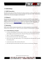
1
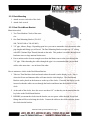
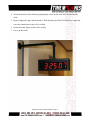
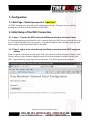
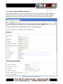
www.css-timemachines.com
WiFi Precision Clocks
“When you absolutely can't afford a time shift”
Installation and Operation Manual
Table of Contents
1 Introduction............................................................................................................................................1
2 Initial Setup............................................................................................................................................2
2.1 WiFi Connection.............................................................................................................................2
2.2 Network..........................................................................................................................................2
2.3 Mounting........................................................................................................................................2
2.3.1 Surface Mounting to Drywall.................................................................................................2
2.3.2 Rack Mounting.......................................................................................................................3
2.3.3 Dual Clock Mount Bracket.....................................................................................................3
3 Configuration.........................................................................................................................................5
3.1 Web Page – Default password is “tmachine”.................................................................................5
4 Initial Setup of the WiFi Connection.....................................................................................................5
4.1.1 Step 1: Connect the WiFi clocks wired Ethernet interface and apply Power........................5
4.1.2 Step 2: Log in to the clock through the Wired connection at the DHCP assigned address....5
4.1.3 Step 3: Setup the WiFi parameters..........................................................................................6
4.2 Web Page Parameter Reference......................................................................................................8
4.2.1 Network..................................................................................................................................8
4.2.2 Time Synchronization.............................................................................................................9
4.2.2.1 SNTP Servers..................................................................................................................9
4.2.2.2 Time Zone.......................................................................................................................9
4.2.2.3 Custom Time Zone..........................................................................................................9
4.2.2.4 SNTP Resync Period.......................................................................................................9
4.2.2.5 Twelve Hour Time..........................................................................................................9
4.2.3 Daylight Savings...................................................................................................................10
4.2.3.1 Daylight Savings(DST Options)...................................................................................10
4.2.3.2 Fixed Day......................................................................................................................10
4.2.3.3 Start/Stop date...............................................................................................................10
4.2.3.4 Hour Bias......................................................................................................................10
4.2.4 Other.....................................................................................................................................11
4.2.4.1 Unit Name.....................................................................................................................11
4.2.4.2 Password.......................................................................................................................11
4.2.5 Alarms...................................................................................................................................11
4.2.5.1 External Connection......................................................................................................11
4.2.6 Brightness.............................................................................................................................12
4.3 Push Button..................................................................................................................................12
4.3.1 Changing the Time Zone......................................................................................................12
4.3.2 Scrolling the IP address........................................................................................................13
4.3.3 Set Parameters to Default.....................................................................................................13
5 Troubleshooting...................................................................................................................................14
5.1 Flashing Seconds..........................................................................................................................14
5.1.1 Lost Link...............................................................................................................................14
5.1.2 Missed NTP packet...............................................................................................................14
Time Machines
6030 South 58th Street, Suite C
Lincoln, NE 68516
Engineered and Manufactured in NEBRASKA, USA
Time Machines is a wholly owned subsidiary of CSS, LLC
402-261-8688
www.css-timemachines.com
Form 0409A
1 Introduction
Time Machines Precision WiFi Clocks (TMPCs) provide an accurate synchronized time source when
you absolutely can't afford a time shift. TMPCs use mains power and communicate with WiFi and
Simple Network Time Protocol (SNTP) to make installation and setup as clean and simple as possible.
Connecting the clock to a WiFi enabled Network is all that needs to be done.
Clocks:
• Digital PoE Clock 2.5” x 4 Red Digits, Black Case
• Digital PoE Clock 2.5” x 6 Red Digits, Black Case
• Digital PoE Clock 2.5” x 4 Green Digits, Black Case
• Digital PoE Clock 2.5” x 6 Green Digits, Black Case
• Digital PoE Clock 4” x 4 Red Digits, Black Case
• Digital PoE Clock 4” x 6 Red Digits, Black Case
• Digital PoE Clock 4” x 4 Green Digits, Black Case
• Digital PoE Clock 4” x 6 Green Digits, Black Case
Part Number
760-240W-000
760-260W-000
760-242W-000
760-262W-000
760-440W-000
760-460W-000
760-442W-000
760-462W-000
Optional Products:
Description
• 2.5” PoE Clock Rack Ear Set, Black
• 2.5” Dual Mount Bracket
• 4” 4-Digit Dual Mount Bracket
Part Number
760-201-000
760-265-000
760-445-000
Installation and Operations Manual | Page 1
2 Initial Setup
2.1 WiFi Connection
The WiFi Clocks require a Wireless Network to be in place to function, as well as 110V power source.
Alternately the clock can be used on a wired network without the requirement of WiFi. Initial setup is
all done with a web browser through the wired connection.
2.2 Network
Beyond connecting to a WiFi network, nothing else is required to get TMPCs up and running. IP,
Netmask, Gateway, and DNS addresses are all setup using Dynamic Hosting Configuration Protocol
(DHCP) by default. Static addresses may be assigned by accessing the configuration web page. The
default time server is set to nist1-chi.ustiming.org but can be changed using the configuration web
page. These processes are described with further detail in the Configuration section.
2.3 Mounting
TMPCs may be surface mounted, rack mounted, or in a dual mount bracket (using two clocks).
Required tools: hammer, drill, 1/4” drill bit, screwdriver and pencil. Mounting options are optional.
2.3.1 Surface Mounting to Drywall
1. Use the provided template to mark the surface with the necessary hole positions for mounting.
(The template is located on the back side of the Quick Setup page included in the clock box.)
2. With a 1/4” drill bit, drill through the two marks.
3. Insert an anchor into each of the 2 holes using a hammer.
4. Insert a screw into each anchor leaving a 1/16-1/8 inch gap between the head of the screw and
the mounting surface.
5. Connect the network cable to the back of the clock.
6. Place the keyhole slots on the back of the clock over the screws and secure it into place.
Installation and Operations Manual | Page 2
2.3.2 Rack Mounting
1. Attach an ear to each side of the clock.
2. Attach clock to rack.
2.3.3 Dual Clock Mount Bracket
Materials needed;
1. Two Time Machine Clocks of the same
size
2. One Dual Mounting Bracket (760-265-
Illustration 1: Attaching Rack Mounting Ears
000, 760-445-000 or 760-465-000)
3. 3/4” pipe, elbows, flange. Depending upon how you want to mount the clock determines what
pipe lengths and fittings you will need. The Dual Mounting Bracket accepts any 3/4” tubing
with NPT (National Pipe Threads) threads on the ends. This product is available through local
hardware stores or large national chain stores.
4. Power outlets need to be near enough to run from the Mains source to the clock through the
3/4” pipe. When threading the cables through the pipe it is recommended that you run both
cables at the same time – one in front of the other.
How to mount two clocks in the Dual Mount Bracket:
1. Take two Time Machine clocks and match where the notch is on the display cover – this is
where the Power and Antenna cables will enter into the clock displays. The Dual Mount
Bracket can be placed on the bottom or on the top of the clocks. If needed, the display can be
inverted so that the cables can run through the bracket and down into the backside of each
clock.
2. At the ends of the clocks, leave the screws out about 1/4” so that they can be inserted into the
key holes on the Dual Mount Bracket.
3. BEFORE you mount the clocks into the bracket, run two power cables through all pipe and
fittings that will be used to hang the clocks. Connect the cables to the clocks and then mount
the clocks into the bracket.
Installation and Operations Manual | Page 3
4. Secure the bracket to the clocks by tightening the screws on the ends of the bracket into the
clock.
5. Begin to tighten the pipe into the bracket. Work from the pipe/Dual Clock Bracket connection
out to the connections for the wall or ceiling.
6. Secure the entire fixture to the wall or ceiling.
7. Power up the clocks
Illustration 2: 2.5" Dual Mount Bracket
Installation and Operations Manual | Page 4
3 Configuration
3.1 Web Page – Default password is “tmachine”
All TMPC parameters are accessed on the configuration web page. The page can be accessed by
pointing any web browser at the IP address of the TMPC.
4 Initial Setup of the WiFi Connection
4.1.1 Step 1: Connect the WiFi clocks wired Ethernet interface and apply Power.
It is important that the network that the clock is connected to have a DHCP server so that the clock can
receive an initial IP address for setup purposes. The initial IP address can be found by using the push
button (double-click) located on the back of the TMPC.
4.1.2 Step 2: Log in to the clock through the Wired connection at the DHCP assigned
address
From a computer on the same network as the clock, open a browser (Internet Explorer, Chrome, Safari,
Firefox) and type in the IP address displayed on the clock when the button is double-clicked for the
URL. This should bring up the login screen of the clock. The default password is “tmachine”.
Installation and Operations Manual | Page 5
4.1.3 Step 3: Setup the WiFi parameters
Once the password is entered, the parameters for the clock will be displayed. It will be important to
know the WiFi SSID to connect to, along with the password and type of security in use. If these
parameters are not set correctly, then the clock will not be able to access the network via WiFi.
Installation and Operations Manual | Page 6
1) Enter the SSID for the access point the clock will use to get the time. This is case sensitive.
2) Enter the Security mode, typically WPA1 or WPA2.
3) Enter the password associated with the access point.
After making changes to the configuration page the “Save Settings” button must be pushed to submit
form data.
To test whether the WiFi parameters take effect, disconnect the Ethernet cable from the clock and make
sure the WiFi Antenna is connected. Power up the clock and see if time is displayed or if at a minimum
double-clicking the button displays an IP address that can be reached on the network. This would mean
that the WiFi system got a connection and an IP address, but that the clock was unable to get the time.
If the letters “AP” are seen to scroll across the display, then connection to the AP was not achieved.
If the clock is not displaying time from the WiFi network, repeat these instructions by connecting to the
wired Ethernet.
4.2 Web Page Parameter Reference
4.2.1 Network
4.2.1.1
DHCP Setup
The wired network connection, if connected to an active network port, will take precedence over the
wireless network connection. Generally it is best to have the WiFi operation based on DHCP and the
wired can be setup as DHCP or Static by unchecking the DHCP checkbox.
By default the network parameters are setup up using DHCP. In order to set static values, uncheck the
DHCP check box and enter new values in the address fields. If the values aren't changed the current
addresses will be kept. The TMPC must be restarted for these changes to take affect. Addresses in
the Network section must be entered in Ipv4, dotted quad, format.
4.2.1.2
Network Parameters, IP, Mask, Gateway, and DNS
The IP address setup is based on version 4 of the IP standards. DNS servers are required if the time
source being used will be a fully qualified domain name rather than an IP address. The clocks will
work best if allowed to access a time server on the local network rather than an Internet based time
source. The Time Machines TM1000A is an inexpesive GPS based NTP server that works well with
the clock products.
Installation and Operations Manual | Page 7
4.2.1.3
MAC
The MAC address field is read only and only for information. It is needed for firmware updates.
4.2.1.4
SSID, Security Mode, and AP Password
These parameters are used exclusively by the WiFi network interface and must be set to match the
Access Point (AP) that the clock will use to synchronize its time. SSID is the name that the AP is
referenced as and the AP Password is the password associated with it. The Security Mode must also
match the setup of the AP and is typically WPA1 or WPA2.
4.2.1.5
Channel and RSSI
Channel and RSSI are read only parameters for information about WiFi performance.
4.2.2 Time Synchronization
4.2.2.1
SNTP Servers
The first entry (Primary SNTP Server) sets the address for the SNTP server. The SNTP server is where
the TMPC gets its timing information. In the case where the Primary SNTP Server is unreachable the
TMPC will fall to the Backup SNTP Server. Both DNS names (time.nist.gov) and IPv4 (192.43.244.18)
formats are accepted.
4.2.2.2
Time Zone
Selecting the Time Zone sets the offset the clock will display from Greenwich Mean Time. All fields
have a predetermined offset except for CUSTOM.
4.2.2.3
Custom Time Zone
If CUSTOM is selected for the Time Zone then this field is editable. Set the desired custom offset by
using the drop down menus to select hours, minutes and (+/-).
4.2.2.4
SNTP Resync Period
The SNTP Resync Period entry sets the period between SNTP requests. Enter the number of hours and
minutes separated by a colon (Hours:Min). The default setting is 0 hours and 10 minutes and is the
recommended update interval.
Installation and Operations Manual | Page 8
4.2.2.5
Twelve Hour Time
Select 12 or 24 hour time. When the box is checked the TMPC is in 12 hour mode, when the box is
unchecked the TMPC is in 24 hour mode. The default setting is 12 hour mode. In the 12 hour mode of
operation AM hours will display a dot in the upper left corner of the display. PM hours will display a
dot in the lower left corner of the display. (In 24 hour mode there will be no indication of AM or PM)
Installation and Operations Manual | Page 9
4.2.3 Daylight Savings
Daylight Savings Time(DST) varies greatly from one country to another and sometimes even within
countries themselves. As a result there are many parameters used to handle all of the various rules that
are in use throughout the world. The default setting uses the rule that is observed by the majority of the
United States.
4.2.3.1
Daylight Savings(DST Options)
The Daylight Saving Time Drop down, allows you to select AUTO, OFF, or CUSTOM. When AUTO
is selected the clocks use the default US Daylight Savings start and stop dates. If OFF is selected the
clock does not adjust for Daylight Savings Time. If CUSTOM is selected the user can specify a custom
start date with a start time and stop date with a stop time. The user can also adjust the bias of the offset.
NOTE* If a US Time Zone is selected then and DST setting of OFF is not allowed. If a DST setting
of OFF is needed the Time Zone should be changed to the corresponding UTC time zone. (i.e. USCTUSA Central is equivalent to UTC -6).
4.2.3.2
Fixed Day
The Fixed Day check box indicates whether or not DST occurs on a specific date. For example, if DST
started on March 1st of every year, the Fixed Day box would need to be checked. The Fixed Day box is
important in that it changes how the Start and Stop parameters function. Based on the Fixed Day
Check box certain drop down menus will be available for editing.
4.2.3.3
Start/Stop date
The Start and Stop Date parameters indicate when DST changes occur.
• The first drop down is only used on floating day start time (i.e. 2nd Sunday of the month). If
fixed day is selected this option is greyed out.
• The second drop down allows the user to select the day of the week you want DST to start or
stop. This parameter is also only available in a floating day scenario.
• The third drop down allows the user specify the month of the start or stop date. This field is
always used.
• The last field is the date, this is only used when a fixed is used (i.e. June 4th).
4.2.3.4 Hour Bias
The Hour Bias parameter allows the user to input a custom hour and/or minute offset if a CUSTOM
Daylight Saving Time is chosen.
Installation and Operations Manual | Page 10
4.2.4 Other
4.2.4.1
Unit Name
This can be any alpha numeric name up to 20 characters long.
4.2.4.2
Password
The password field displays the current password. To change it, enter a new password, push Set and
Restart Clock. TMPC passwords are limited to12 characters. The default password is “tmachine”
4.2.5 Alarms
The TMPC has the capability of signaling 24 alarms throughout the course of a single day. Alarm
entries are to be separated by semicolons with no spaces. The hour, entered in 24 hour time, at which
the alarm is to be set off is entered first and followed by the minute, the two are to be separated by a
colon. The last entry is the duration, in seconds, that the alarm is to sound, it is limited to a maximum
of 59 seconds. The minutes and seconds are to be separated by a single dash. Simply deleting an alarm
from the form won't disable the alarm, the next time the web page is brought up the alarm will still be
shown and still be active. In order to deactivate an alarm the duration must be set to 0. Only then will
the alarm no longer be listed when the web page is revisited. The default setting is to have no alarms
set.
Example alarm string:
8:0-3;12:0-3;13:0-3;17:0-3
This example string sets 4 alarms all on the hour and for a duration of 3 seconds.
4.2.5.1
External Connection
External connection will require the user to make a connection from the clock's internal relay to an
external system. The Time Machine Clock is only able to close a relay to initiate an external alarm
system function. Wiring for the internal relay closure:
Maximum Voltage: 125 VDC, 150VAC
Maximum Switched Current: 1A
Maximum Carrying Current: 1A
Maximum Switch Power: 30W (DC), 60VA (AC)
Installation and Operations Manual | Page 11
Illustration 3: Connector for Relay
Illustration 4: Relay Connection Diagram
4.2.6 Brightness
This parameter allow the user to control the brightness of the display. There are three settings that are
selectable.
•
DEFAULT, the brightest setting
•
MEDIUM
•
LOW, the lowest setting.
4.3
Push Button
4.3.1 Changing the Time Zone
Using the push button provides a quick way to set the time zone with out having to access the
configuration web page. With every push of the button the GMT offset decreases by 1. Since the
default offset is -5, pushing the button once would set the offset to -6. Once the negative offset reaches
Installation and Operations Manual | Page 12
its limit(-11) the next offset is the maximum positive offset(14).
4.3.2 Scrolling the IP address
The push button also provides a quick way to determine the IP address of the TMPC. A rapid double
push of the button will cause the IP address to scroll across the display.
4.3.3 Set Parameters to Default
One way to set all parameters to their factory default values is to hold the button on the back of the
clock down when the clock is powered up. If done successfully, three “8's” will scroll across the
display before entering the usual start up routine.
Installation and Operations Manual | Page 13
5 Troubleshooting
5.1 Flashing Seconds
There are two instances when the seconds (6 digit clock) and the AM/PM dots will flash to indicate a
problem.
5.1.1 Lost Link
If the seconds and the AM/PM dots are flashing it is possible that the link was lost, check to make sure
everything is connected properly at both ends of the cable.
5.1.2 Missed NTP packet
If an NTP packet was sent but a reply wasn't received the seconds and AM/PM dots will flash. This can
happen every now and then, the flashing will stop as soon as the TMPC completes a successful send
and receive cycle. If the primary server can no longer be reached the backup server will become the
primary server. This is observable by looking at the configuration web page, if the primary and backup
servers display the same address(primary will be in IPv4 format) than this scenario has occurred. If
both servers fail the seconds and AM/PM dots will continue to flash until the issue is resolved. Log into
the configuration web page and set new SNTP servers.
Installation and Operations Manual | Page 14