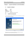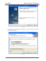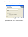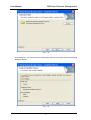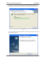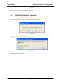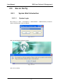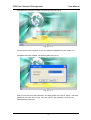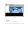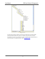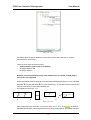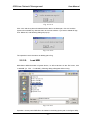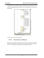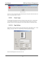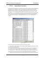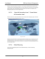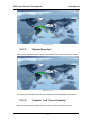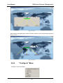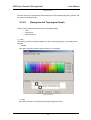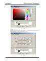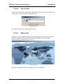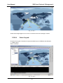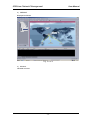
1
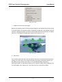
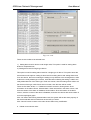
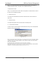
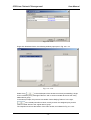
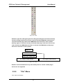
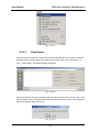
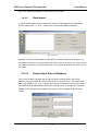
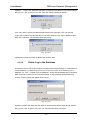
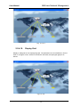
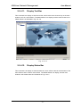
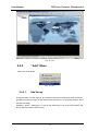
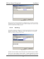
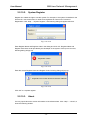
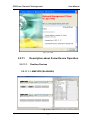
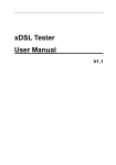
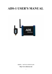
AMXview
AMXview Network Management
User Manual
AMXview 7.2
Network Management
for AMX32
User Manual
i
AMXview Network Management
User Manual
Table of Contents
I. HISTORY ........................................................................................................................................... 4 CHAPTER 1 SYSTEM INSTALLATION AND UNINSTALLATION ................................................................... 1 1.1. SYSTEM CONFIGURE ................................................................................................................................ 1 1.2. INSTALL XVIEW SYSTEM ............................................................................................................................ 1 1.3. UNINSTALL XVIEW SYSTEM ........................................................................................................................ 6 CHAPTER 2 2.1. SYSTEM HELP .................................................................................................................... 7 MYSQL ................................................................................................................................................. 7 2.1.1. Install Database .......................................................................................................................... 7 2.1.2. Init Database .............................................................................................................................. 7 2.2. USE ON THE FLY ...................................................................................................................................... 8 2.2.1. System Brief Introduction ........................................................................................................... 8 2.2.1.1. System Login .......................................................................................................................................... 8 2.2.1.2. Interface .............................................................................................................................................. 10 2.2.2. “File” Menu .............................................................................................................................. 23 2.2.2.1. Data Export .......................................................................................................................................... 24 2.2.2.2. Data Import ......................................................................................................................................... 25 2.2.2.3. Delete Alarm Data in Database ............................................................................................................ 25 2.2.2.4. Delete Log in the Database .................................................................................................................. 26 2.2.2.5. Load MIB .............................................................................................................................................. 27 2.2.2.6. Remote Access to Manager ................................................................................................................. 28 2.2.2.7. Switch to Local Management .............................................................................................................. 29 2.2.2.8. Login .................................................................................................................................................... 29 2.2.2.9. Cancel Login ......................................................................................................................................... 30 2.2.2.10. Page Setting ..................................................................................................................................... 30 2.2.2.11. Print Topological Graph ................................................................................................................... 31 2.2.2.12. Exit System ...................................................................................................................................... 31 2.2.3. “Edit” Menu .............................................................................................................................. 31 2.2.3.1. View and Edit Properties ..................................................................................................................... 32 2.2.3.2. Device Alarm Condition ....................................................................................................................... 33 2.2.3.3. Refresh Device List ............................................................................................................................... 34 2.2.3.4. Search Proxy ........................................................................................................................................ 34 2.2.3.5. Search Serial Devices ........................................................................................................................... 35 2.2.3.6. Cancel Topological Graph Operation ................................................................................................... 36 2.2.3.7. Redo Topological Graph Operation ...................................................................................................... 36 2.2.3.8. Delete Current Device Node ................................................................................................................ 36 2.2.3.9. Delete All Device Nodes ....................................................................................................................... 36 2.2.4. “View” Menu ............................................................................................................................ 37 2.2.4.1. Display Device Topological Graph ........................................................................................................ 37 2.2.4.2. Clear Information in the Trap Alarm Window ...................................................................................... 37 2.2.4.3. Clear Information in the System Log Window ..................................................................................... 38 2.2.4.4. Clear Information in Http Session Window.......................................................................................... 38 2.2.4.5. Clear Information in Remote Response Window ................................................................................. 38 ii
AMXview Network Management
User Manual
2.2.4.6. Display in Actual Size ........................................................................................................................... 38 2.2.4.7. Zoom Ratio .......................................................................................................................................... 38 2.2.4.8. Display Scale ........................................................................................................................................ 39 2.2.4.9. Display Boundary ................................................................................................................................. 39 2.2.4.10. Display Grid ..................................................................................................................................... 40 2.2.4.11. Display Tool Bar ............................................................................................................................... 41 2.2.4.12. Display Status Bar ............................................................................................................................ 41 2.2.5. “Add” Menu ............................................................................................................................. 42 2.2.5.1. Add Group ........................................................................................................................................... 42 2.2.5.2. Add Proxy ............................................................................................................................................ 43 2.2.5.3. Desktop Device .................................................................................................................................... 44 2.2.6. “Manage” Menu ...................................................................................................................... 45 2.2.6.1. System Account Administration .......................................................................................................... 45 2.2.6.2. Manage User Groups ........................................................................................................................... 48 2.2.6.3. Modify Password ................................................................................................................................. 53 2.2.6.4. Start Http Service ................................................................................................................................ 54 2.2.6.5. Stop Http Service ................................................................................................................................. 55 2.2.6.6. Set Serial Port ...................................................................................................................................... 55 2.2.6.7. Trap Information Management ........................................................................................................... 56 2.2.6.8. Log Information Management ............................................................................................................. 58 2.2.6.9. Set Poll Time ........................................................................................................................................ 60 2.2.6.10. Set Poll Time for Serial Port ............................................................................................................. 61 2.2.6.11. Configure Device Address ............................................................................................................... 61 2.2.6.12. Set Raisecom‐Server Communication Parameters .......................................................................... 63 2.2.7. “Tool” Menu ............................................................................................................................. 63 2.2.7.1. “Select All” and Cancel Select All” ....................................................................................................... 64 2.2.7.2. “Select Device Primitive” / “Cancel Select Device Primitive” .............................................................. 65 2.2.7.3. “Select All Connection Lines” / “Cancel Select All Connection Lines” ................................................. 66 2.2.7.4. Default Boundary ................................................................................................................................ 66 2.2.7.5. “Optimal Boundary” ............................................................................................................................ 67 2.2.7.6. “Combine” and “Cancel Combine” ...................................................................................................... 67 2.2.8. “Configure” Menu .................................................................................................................... 68 2.2.8.1. Background of Topological Graph ........................................................................................................ 69 2.2.8.2. Size of Grid .......................................................................................................................................... 71 2.2.8.3. Metric Unit .......................................................................................................................................... 71 2.2.8.4. Select Layout ....................................................................................................................................... 72 2.2.9. “Window” Menu ...................................................................................................................... 74 2.2.9.1. Maximize Topological Window ............................................................................................................ 74 2.2.9.2. Minimize Topological Window ............................................................................................................ 74 2.2.9.3. Cascade Window ................................................................................................................................. 74 2.2.9.4. Current Open Window ........................................................................................................................ 75 2.2.10. “Help” Menu ............................................................................................................................ 75 2.2.10.1. Home Page ...................................................................................................................................... 75 2.2.10.2. System Register ............................................................................................................................... 76 2.2.10.3. About .............................................................................................................................................. 76 iii
AMXview Network Management
User Manual
2.2.11. Description about Xview Device Operation .............................................................................. 77 2.2.11.1. CHAPTER 3 Desktop Devices .............................................................................................................................. 77 ATTENTIONS ..................................................................................................................... 78 3.1. COLORS ON THE TOPOLOGICAL GRAPH ...................................................................................................... 78 3.2. CHOICE OF MODE AND LEVEL OF ALARM ................................................................................................... 78 3.3. REMOTE ACCESS ................................................................................................................................... 78 3.4. ICONS FOR DISPLAYING REPLACED DEVICES ................................................................................................. 78 I.
History
Rev.
Date
Author(s)
Remarks
1.0
28.11.09
AZI
Initial document
1.1
27.09.10
AZI
Changes after Review.
iv
AMXview Network Management
Chapter 1
1.1.
User Manual
System Installation and Uninstallation
System Configure
CPU:
>PM1.0G
Memory:
>256M
Hard Disk:
>100M
Screen Resolution: >1024*768
Network Adapter:
10M/100M
OS:
Windows98/Windows2000/WindowsXP
1.2.
Install Xview System
You may run directly the installation program on the CD, i.e. click install.exe to run the install
wizard, and following dialog will appear:
Fig. 1-1
During this process, you may click the “Cancel” button to quit installation. Wait for the
progress bar to complete, and following dialog will pop up:
-1-
User Manual
AMXview Network Management
Fig. 1-2
You may click the “Cancel” button to quit installation, or click “Next” button to go on, and then
following dialog will appear:
Fig. 1-3
-2-
AMXview Network Management
User Manual
You may click the “Cancel” button to quit installation, or select “I accept the terms in the
license agreement” and click “Next” button to go on, and then following dialog will appear:
Fig. 1-4
In the dialog box, you may enter your information (User Name and Organization) and select
who shall this application install for, and then click “Next” button and following dialog will
appear:
-3-
User Manual
AMXview Network Management
Fig. 1-5
In the dialog box, you shall specify the install folder, and then click “Next” button and following
dialog will appear:
Fig. 1-6
-4-
AMXview Network Management
User Manual
You may click “Cancel” button to quit installation, or click “Back” button to return to the
previous dialog, or click “Install” button to go on installing and following dialog will appear:
Fig. 1-7
You may click “Cancel” button to quit installation. Waiting for the progress bar to complete and
following dialog shall pop up:
-5-
AMXview Network Management
User Manual
Fig. 1-8
Click “Finish” button and the installation completes.
1.3.
Uninstall Xview System
Run “Uninstall NetworkXView”, the following dialog will appear.
Fig. 1-9
Single click “Yes” and following dialog will appear:
Fig. 1-10
Wait for Uninstall to complete.
-6-
AMXview Network Management
Chapter 2
2.1.
2.1.1.
User Manual
System Help
mySQL
Install Database
Click “Install Database” in the menu to install the database, i.e. “Start” →”All Programs”→”
NetworkXView” →”install Database”, and following dialog will appear:
Fig. 2-1-1
The user name and password needed here are all “root”. Enter them and click “OK”, then the
database is installed.
2.1.2.
Init Database
Click “Init Database” in the menu to initialize the database, i.e. “Start” →”All Programs”→”
NetworkXView” →”Init Database”.
-7-
AMXview Network Management
User Manual
2.2.
Use on the Fly
2.2.1.
2.2.1.1.
System Brief Introduction
System Login
Run “Xview” (i.e.: “Start” →”All Programs”→” NetworkXView” →”NetworkXView”) to start the
system, following login screen will appear:
Fig. 2-2-1-1
Click “ok” and following dialog will appear:
Fig. 2-2-1-2
Click “ok” to continue,
-8-
AMXview Network Management
User Manual
If database has not been installed, the following dialog will pop up:
Fig. 2-2-1-3
The setup will not be continued, so you may install the database first (see chapter 2.1).
If database has been installed, the following dialog will pop up:
Fig. 2-2-1-4
Enter correct user name and password in the dialog (initial user name is “admin”, with blank
password), then click “OK” to login. If the user name or the password is incorrect, the
following dialog will pop up:
-9-
AMXview Network Management
User Manual
Fig. 2-2.1-5
Click “OK” to return to the preview dialog to login; after three false inputs, the system will be
terminated. If you want to login, you shall run the program again.
2.2.1.2.
Interface
The main window is as follows:
Fig. 2-2-1-6
On top is the Menu Bar as indicated in 2-2-1-7, including: File, Edit, View, Add, Manage, Tool,
Configure, Window, and Help.
The letters inside “[]”following each menu are combined shortcut keys, such as “Alt+F” is the
shortcut key for File Menu.
Fig 2-2-1-7
The largest window on the right is the window of topological graph, as in the following
- 10 -
AMXview Network Management
User Manual
example:
Fig. 2-2-1-8
The topological windows are respectively the four branches of
1: Nmsc485,
2: Other Groups,
3: Agent and
4: Nms485 and their own device tree topological graphs.
On left side of the main window is wizard region, including list of resources and data of MIB as
indicated in Fig. 2-2-1-9:
- 11 -
User Manual
AMXview Network Management
Fig. 2-2-1-9
The above figure shows the window of tree structure for MIB and in this window related
information loaded in MIB can be viewed. For example, Device C04 has 6 nodes as
C04_address, C04_port, C04_protmode, C04_byte 1, and C04_byte2. Single click each to
view its description. For detailed operation, refer to File Menu in 2.2.2.
- 12 -
AMXview Network Management
User Manual
Fig. 2-2-1-10
The above figure shows the window of resource list. It lists all the devices for network
management in a tree form.
There are three types of devices mainly:
-
desktop devices (refer to 2.2.11 for details),
-
5U plug-in devices and
-
6U plug-in devices.
Remark: arcutronix GmbH does only offer desktop devices. The 5U- and 6U-plug-in
devices are not supported.
Horizontal medium-sized rectangular icon represents desktop agent (agent 1.0/3.0), indicated
with letter D. The left side of the D icon is the local end (L), its right side is the remote end (R),
and the traverse line in the middle indicates self.
As indicated in Figure 2-2-1-11.
L
S
L
R
L
A
B
C
S
R
D
Fig. 2-2-1-11
Each component of the icons are in four colors: Red, Green, Gray, and Yellow, where Red
indicates Device Alarm, Green represents Normal, Gray means Offline, and Yellow stands for
- 13 -
User Manual
AMXview Network Management
Just Added/Waiting for System to Update. A has 27 kinds of different effective combinations
and B has 4 kinds of different combinations. Examples are cited in Figure 2-2-1-12:
Fig. 2-2-1-12
From the above figure, there are altogether 5 device groups Hamburg, Hannover, Berlin,
Hannover, and Munich. Take “Hamburg” and “Hannover” as examples.
Under “Hamburg” Device Group there are Agents *Agent IV_10.10.0.101 and *Agent
II_10.101.0.116”, where the Integration Frame *Nmsc485 is mounted under the “Agent
II_10.101.0.116”. The combination of these three items is all in the status of self, local alarm,
and remote offline. The devices mounted underneath are all local alarm and remote offline.
The Device Group “Hannover” refers to desktop agent “Agent III10.101.0.102” and its
combination is in self normal, local and remote alarm status. Device *c16_15 is mounted
underneath, and the combination is in a local alarm and remote offline status.
Left-click to choose node, or right-click to show the menu and operate accordingly. The
pop-up menu is as follows:
- 14 -
AMXview Network Management
User Manual
Fig. 2-2-1-13
1. Display the device topological graph:
Perform this operation and the network topological graph of the selected device will be shown
in the main window, the topological graph is displayed in single layer, and operations such as
selection of topological graphs and even boundary points can be performed in the Tool Menu,
refer to 2.2.7 Tool Menu for details and it is shown as in Figure 2-2-1-14:
Fig. 2.2-1-14
2. Add a Proxy
If the chosen target is the name of an area group, under the circumstance of having enough
privilege, the “Add a proxy” item shall become black (indicating accessibility) and thus you
may add a proxy by clicking “Add a proxy” icon, and following dialog shall pop up:
After login as Admin or authorized by Admin as an account for adding a proxy, adding a proxy
can be operated. Click “Add A Proxy”, the system will pop up the following dialog:
- 15 -
AMXview Network Management
User Manual
Fig. 2-2-1-15
Operation: Enter the IP address, name, and description of SNMP proxy (shown in the figure),
click “Ok”, and the proxy of “Telecom Site No. 1” is added; meanwhile, the content in the
resource list will be refreshed, and you may find a newly-added proxy in the list.
3. View or Edit Properties:
Under the circumstances that there is accessibility and this item is effective, here you may
view or edit relevant properties of device nodes, proxies, and area groups. You may also
double click the mouse for this item and under the circumstances that there is accessibility
and this item is effective, you can view or edit relevant properties of device nodes, proxies,
and area groups.
The descriptions and names of area groups can be modified; and the descriptions, names
and proxy IP addresses of SNMP proxies can be modified; while the descriptions, the local
names, the remote names, IP addresses, alarm settings, and other attributes of the ordinary
plug-in card devices and desktop devices can be modified.
Refer to “View and Edit Properties” in “Edit” for its operation process.
4. Set Alarm Conditions for this Device:
Here you may view or modify the setting of device alarms. Refer to the operation of “View
device alarms” in the “Edit” menu for detailed information.
5. Batch Process Alarm Conditions:
Here you may set or modify alarm status of devices in batches. Click “Batch process of alarm
conditions” and following dialog will pop up:
- 16 -
AMXview Network Management
User Manual
Fig. 2-2-1-16
There are two modes to be selected here:
1) Setting alarm level for device under single node; This option is used for setting alarm
levels for multiple devices;
2). Setting alarm level for single type device.
This option is used for setting alarm levels for a single type of device. This option has at the
same time two sub-options: setting of alarm level for existing device and setting alarm level
for a new device, the former meaning the setting is only effective to the existing device, while
invalid to the newly added type of device, while the latter indicating the setting is valid to the
newly added devices of the same type. If both are chosen, then the setting will be valid to all
the devices of this type, while if both are not chosen, then this item will be invalid.
There are five alarm levels, i.e.: Treated as no alarm: No action; Hinting alarm: Show
information in the alarm column; General alarm: Show information in the alarm column, and
save the content of the alarm in database; Serious alarm: Show information in the alarm
column, save the content of the alarm in database, and show the device with serious alarm in
red in the topological graph.
Click “Ok” button after having selected alarm level; the system will set the alarm property of
the device selected and its sub-devices as the level you select.
Click “Cancel” button to return to the main window without any modification.
6. Delete current device node:
- 17 -
AMXview Network Management
User Manual
Here you may delete selected devices and their sub-devices. Refer to the operation of
“Delete current device node” in the “Edit” menu for detailed information.
7. Delete all device nodes:
Here you may delete all device nodes. Refer to the operation of “Delete all device nodes” in
the “Edit” menu for detailed information.
8. Refresh Device List:
To re-inspect all connected devices and device nodes set before, and then refresh the
resource list.
9. Refresh this proxy:
To re-inspect the properties and connection status of selected proxies.
10. Set temperature threshold:
To set the range of normal temperature of NmsC485 while running. Click “Set temperature
threshold” to pop up following dialog:
Fig. 2-2-1-17
Enter an appropriate range of temperature in the dialog (in the format as illustrated, default:
10.0/40.0). Click “Yes” to save the setting, or click “Cancel” to return to the main window
without any modification.
The inspection area is at the bottom of the main window, as follows:
When right single-click the mouse to add a new device group and perform “View and Edit
Properties”, the following window will pop up as in Fig. 2-2-1-18.
- 18 -
AMXview Network Management
User Manual
Fig. 2-2-1-18
Single click Distribute Device, the following window pops up as in Fig. 2-2-1-19:
Fig. 2-2-1-19
Select Proxy,
in the middle part of the window turns black (accessibility). Single
click it to add the proxy “Shanghai Telecom” and it’s under mounted device into the newly
added device group.
In the same principle, this process is reversible. Select “Beijing Telecom” in the right,
in the middle part will turn black, namely to return the assigned proxy and it’s
under mounted device to the original device group.
The inspection area is at the bottom of the main window, as indicated in Fig. 2-2-1-20:
- 19 -
User Manual
AMXview Network Management
Fig. 2-2-1-20
Here you may inspect Trap alarm information, system log, connection status of http session,
response status during remote management, and debug information of the program.
1. Trap Alarm
Single click “Trap Alarm” to show the above window. And the Trap Alarm item is heaved
whereby to view the Trap alarm information. Can also double click” Trap Alarm”, to show the
following window:
Fig. 2-2-1-21
2. System Log
Single click “System Log” and this item is heaved, to show the following window:
Fig. 2-2-1-22
Thus the system log can be viewed. The above figure shows the log records for device
operation and alarm management.
3. Http Session
Single click “Http Session’ and this item will be heaved to show the following window:
- 20 -
AMXview Network Management
User Manual
Fig. 2-2-1-23
There is no display of information as Http service has not yet been started. After Http service
is launched in the management menu, the following window appears as follows:
Fig. 2-2-1-24
It can now be seen that this machine has been started as a server. After conditions in the
attentions are satisfied, remote company can now login.
The accessibilities to local end and remote end are the same, i.e. if the current local end is
logged in as an Admin, the remote end is also accessible as an Admin. Likely, if current local
end is logged in as an ordinary account, remote end is also accessible with an ordinary
account.
Attention: It is not allowed for both ends to login at the same time.
4. Remote Response
Single click “Remote Response and this item is heaved, to show the following window:
Fig. 2-2-1-25
There is no output of information in the window as no user has logged in from the remote end.
After a remote login, the following window appears:
- 21 -
AMXview Network Management
User Manual
Fig. 2-2-1-26
You can see now user with IP of 192.168.0.18 has successfully logged in the system.
Operation information such as the access right of the remote computer can be viewed in this
window besides login information.
Among the four items of “Trap Alarm”, “System Log”, “Http Session”, and “Remote Response”,
only “Trap Alarm” can be double clicked to view the alarm prompt window. However, “System
Log”, “Http Session”, and “Remote Response” can be right clicked to show the clear output
menu and the output information can be cleared when it is singled clicked.
Besides, there are a series of shortcut icons on the main interface as shown in Fig. 2-2-1-27:
Fig. 2-2-1-27
Mouse can be moved to them to view functions of each icon.
Fig. 2-2-1-27 shows the shortcut icons to be operated in Add Menu.
Take the “
” icon in the following figure as an example, you can see there are totally four
such icons, representing agent 1.0, agent 2.0, agent 3.0, and agent 4.0, respectively, of which
agent 1.0 is desktop agent, agent 2.0 is card agent, agent 3.0 is the upgrade version of agent
1.0, and agent 4.0 is the upgrade version of agent 2.0.
- 22 -
AMXview Network Management
User Manual
Fig. 2-2-1.28
Attention: agent 2.0 is 6U typed, agent 4.0 is 5U typed, and agent 2.0 cannot be directly
used for 5U plug-in devices, but can be under mounted with NMST485, and further be
connected into 5U plug-in device from NMST485 to be connected in series parallel.
Similarly, agent 4.0 cannot be directly connected to 6U plug-in card device, but can be
under mounted with NMSC485 and further connected from NMSC485 into 6U plug-in
device for connection in series parallel.
agent 2.0
NMST485/ NMSC485
NMST485/ NMSC485
5U Plug-in Card Device
…
6U Plug-in
Card Device
Fig. 2-2-1-29
Remark: arcutronix GmbH does only offer desktop devices. The 5U- and 6U-plug-in
devices are not supported.
2.2.2.
“File” Menu
“File” menu is as follows:
- 23 -
AMXview Network Management
User Manual
Fig. 2-2-2-1
2.2.2.1.
Data Export
Current information of device nodes in the system is exported here. Its function is to backup
the information of device nodes in the system. On the “File” menu, click “Data export”, i.e.:
“File” →”Data export”, and following dialog will appear:
Fig. 2-2-2-2
Choose the path for saving in the dialog, enter the name of backup file, and click “save”. If the
file has already existed, new information of the node will be saved in the file. If the file doesn’t
exist, then following dialog will pop up:
Fig. 2-2-2-3
- 24 -
AMXview Network Management
User Manual
Click “Yes” and Export (Backup) of node information completes.
2.2.2.2.
Data Import
To import backup data of device nodes to the system is called data recover (data import),
execute “Data import”, i.e. “File” →”Data import”, and following dialog will appear:
Fig. 2-2-2-4
Operation: Choose the path where the backup file is located (as the path in the figure: my
document), choose the name of the backup file in the column of file name, click “Open” button.
The system will import your backup file into the current system and refresh the resource list of
the system.
2.2.2.3.
Delete Alarm Data in Database
This function enables managers with enough privilege to manage data in the current
database, namely to delete all or part of alarm data. On the “File” menu, click “delete alarm
data in the database”, (i.e. “File” →”delete alarm data in the database”); device alarm data in
the database will be deleted after confirmation. Data cannot be recovered once it has been
deleted, so this operation shall be taken with scrutiny. Following dialog will appear while
running:
Fig. 2-2-2-5
- 25 -
User Manual
AMXview Network Management
Operation: Enter in the dialog the date span for the data to be deleted, input format shall be
like yyyy-mm—dd, as (2010-1-21); click “Yes” and following dialog will appear:
Fig 2-2-2-6
Click “Yes” and the system will delete all alarm data in the date span; click “No” and the
system will not delete any data but return to the main window. If you want to delete all alarm
data, click “Delete all”, and following dialog will pop up:
Fig. 2-2-2-7
Operations here are the same as deleting part of alarm data.
2.2.2.4.
Delete Log in the Database
As operation above, this function enables managers with enough privilege to manage data of
current database, i.e. delete all or part of log. On the “File” menu, click “Delete log in the
database” (i.e. “File” →”Delete log in the database”), all log shall be deleted after confirmation.
Data cannot be recovered once it has been deleted, so this operation shall be taken with
scrutiny. Following dialog will appear while running:
Fig. 2-2-2-8
Operation: Enter in the dialog the date span for the data to be deleted, input format shall be
like yyyy-mm—dd, as (2010-1-21); click “Ok” and following dialog will pop up:
- 26 -
AMXview Network Management
User Manual
Fig. 2-2-2-9
Click “Yes” and the system will delete all alarm data in the date span; click “No” and the
system will not delete any data but return to the main window. If you want to delete all logs,
click “Delete all”, and following dialog will pop up:
Fig. 2-2-2-10
The operation here is the same as deleting part of log.
2.2.2.5.
Load MIB
MIB refers to MIB information of system device, i.e. OID of devices. On the “File” menu, click
“Load MIB” (i.e. “File” →”Load MIB”), following dialog will appear while running:
Fig. 2-2-2-11
Operation: choose path of MIB file to be loaded in the dialog (as the path in the figure: MIB),
- 27 -
AMXview Network Management
User Manual
choose MIB file name in the file name column, click “Open” button. The system will load MIB
file information into current system, meanwhile refresh Tianyuan MIB information list in the
system, and display MIB structure information in the “Tianyuan MIB” column. As shown in the
following figure:
Fig. 2-2-2-12
Click one node to show relevant MIB property.
2.2.2.6.
Remote Access to Manager
Remote access of manager is to login remote computer which runs this program through IP
address from local computer for remote inspection. Execute “Remote access to manager”
(i.e. “File” →”Remote access of manager”), and following dialog will appear:
- 28 -
AMXview Network Management
User Manual
Fig. 2-2-2-13
If remote end has started Http service and no firewall is opened, enter in the dialog the correct
IP address of the computer you want to login (like: 192.168.0.1), username and password
(username and password of remote manager), to connect to remote Manager for remote
management.
This function is used for device management on WAN.
2.2.2.7.
Switch to Local Management
This function is used with remote login. While you are connecting to remote computer for
remote management, “switch to local management” will become black (indicating
accessibility), and you may click “Switch to local management” to switch back to manage
local devices. Operation: “File” →”Switch to local management”, or click the “Switch to local
management” icon in the main window to manage local devices.
2.2.2.8.
Login
After you have canceled login, “Login” will become black (indicating accessibility). You shall
first login before performing any management. On the “File” menu, click “Login”, i.e.
“File”→”Login”, or click the relevant “Login” icon in the main window. Following dialog as
indicated in Fig. 2-2-2-14 will appear after you have performed this operation:
Fig. 2-2-2-14
Operation: Enter in the dialog username and password and click “Ok”, the system will login to
the main window. If the username or password is incorrect, following dialog will appear:
- 29 -
AMXview Network Management
User Manual
Fig. 2-2-2-15
Click “Ok” to return to login dialog. After three false inputs, the system will be terminated. You
shall run the program again to continue.
2.2.2.9.
Cancel Login
To cancel login is to logout the current user. Execute “Cancel Login” (“File”→”Cancel Login”,
or click relevant “cancel login” icon in the main window) to logout current user. Then any
operation of devices cannot be performed, but the system still has not quitted after logout.
2.2.2.10.
Page Setting
Page Setting is to set the system for printing the page. Execute “Page Setting” (“File”→”Page
Setting”), on the “File” Menu, click “Page Setting” and following dialog will pop up:
Fig. 2-2-2-16
Enter into the dialog items to be set and click “Ok”.
- 30 -
AMXview Network Management
2.2.2.11.
User Manual
Print Topological Graph
To print currently opened topological graph of devices, execute “Print Topological Graph”.
Operation: ”File” →“Print Topological Graph”, on the “File” menu, click “Print Topological
Graph” and following dialog will pop up:
Fig. 2-2-2-17
Choose correct printer and click “Ok”.
2.2.2.12.
Exit System
You may perform this operation if you want to exit the system. On the “File” menu, click “Exit
the system”, and following dialog will appear:
Fig. 2-2-2-18
Click “Yes”.
2.2.3.
“Edit” Menu
“Edit” menu is as follows:
- 31 -
User Manual
AMXview Network Management
Fig. 2-2-3-1
2.2.3.1.
View and Edit Properties
To view or edit properties is to view or edit the properties of device node or proxies. Operation:
choose in the resource list the device node or proxies whose property you want to view or edit.
You may execute this command if you have sufficient privilege. (“Edit” →”View or Edit
Properties”)
For example, choose one proxy and the window is as follows:
Fig. 2-2-3-2
In the basic information column, you may edit property value for the device. To cancel current
modification, just click “cancel” button; to confirm current modification, click “Ok” button.
Meanwhile the system will return to the main window.
- 32 -
AMXview Network Management
2.2.3.2.
User Manual
Device Alarm Condition
According to the privilege level of its alarm, the device alarm conditions may be divided into 4
categories, that is: Treated as no alarm, hinting alarm, general alarm and serious alarm.
Setting device alarm conditions: in the resource list choose the device node or proxy you
want to set, as in the case of msc485, execute the command in the menu (“Edit”→”View
Device Alarm”) if you have sufficient privilege; or choose in the resource list the device node
or proxy you want to set with mouse and then right-click on the item. On the pop-up menu
click “Device Alarm Conditions”. Following window as in Fig. 2-2-3-3 will appear while
running:
Fig. 2-2-3-3
Herein, the value of every property of alarm may have four choices:
1. Hinting Alarm: While receiving Trap information, display relevant information in the Trap
Column on the Inspection Panel.
2. Secondary Alarm: While receiving Trap information, display relevant information in the
Trap Column on the Inspection Panel, and besides, save the information into database.
3. Important Alarm: While receiving Trap information, display relevant information in the
Trap Column on the Inspection Panel, and besides save the information into database.
4. Urgent Alarm: While receiving Trap information, display relevant information in the Trap
- 33 -
AMXview Network Management
User Manual
Column on the Inspection Panel, save the information into database, and email the alarm to
the system users for them to edit value of alarm property, to cancel the current modification by
clicking “Cancel” button, and to accept current modification by clicking “Ok” button. The
system will return to the main window at the same time..
If the alarm types set for the devices are the same, you may choose “Batch process of alarm
conditions” to perform those operations rapidly. Operation: click the device node or proxy in
the resource list, right-click on the item, on the pop-up menu click “Batch process of alarm
conditions”, and in the pop-up dialog choose the type and click “Ok”.
2.2.3.3.
Refresh Device List
In the resource list choose the device node or proxy you want to refresh, execute the
command on the menu (“Edit” →”Refresh Device List”) if you have sufficient privilege; or you
may choose the device node or proxy you want to refresh in the resource list and right-click
on the item, then click “Refresh Device List” on the pop-up menu. In execution the system
shall search automatically devices from SNMP proxy and then display in the resource list for
user to perform operations according to the device tree.
2.2.3.4.
Search Proxy
To search Proxy is to search proxy within the specified range of IP addresses to determine
whether proxies exist or not. Operation: “Edit” → ”Search Proxy”, or click on the relevant icon
on the main window. Following dialog will appear while running:
Fig. 2-2-3-4
There are two options in the dialog box: 1. Single IP, and 2. Address Field. Select of the
former can only modify the initial address, while selection of the latter is to modify both initial
address and terminal address. Enter a search range of IP address in the dialog and click “Ok”,
the system will enter search process. The following window will appear:
- 34 -
AMXview Network Management
User Manual
Fig. 2-2-3-5
The proxy system has found will be automatically added into “Other Group” in the resource
list at the same time.
Fig . 2-2-3-6
Note: While searching as per address, it is required for the fields of initial address and
the fields for the terminal address to be the same, i.e. the addresses for the first three
fields are the same and the initial address shall be smaller than the terminal address
for the fourth fields.
2.2.3.5.
Search Serial Devices
To search serial-port devices is for system to search devices of specified types within the
appointed address range. Operation: “Edit” → “Search Serial Device” → Select Device Type
and Address Range → Click Search.
- 35 -
AMXview Network Management
User Manual
Fig. 2-2-3-7
Note: Open serial port prior to searching serial devices.
2.2.3.6.
Cancel Topological Graph Operation
To cancel topological graph operation is: When you have any operation on the topological
graph, the system will record them, and these operations can be cancelled by executing this
command. Operation: “Edit” →”Cancel Topological Graph Operation”, or click on the relevant
icon on the main window.
2.2.3.7.
Redo Topological Graph Operation
To redo topological graph operation is: when you execute “Cancel Topological Graph
Operation”, the system will record them, and the system may redo the operation which was
cancelled by executing this command. Operation: “Edit” →”Redo Topological Graph
Operation”, or click the relevant icon on the main window.
2.2.3.8.
Delete Current Device Node
To delete current device node is to delete specified device nodes or proxies in the resource
list, and this command can be executed if you have sufficient privilege.
Operation: Select device nodes or proxies you want to delete, if you have the privilege you
may execute the command on the menu (“Edit”→”Delete Current Device Node”); or select the
device node or proxy to be deleted, right-click on the item and click “Delete Current Device
Node” on the pop-up menu. After confirmation, the system will delete current device node and
sub-device nodes; besides, information relevant to the device or its sub-devices in the
database will be deleted. So this operation shall be taken with scrutiny.
2.2.3.9.
Delete All Device Nodes
To delete all device nodes is to delete all specified device nodes or proxies in the resource list,
and this command can be executed if you have sufficient privilege.
- 36 -
AMXview Network Management
User Manual
Operation: “Edit” →”Delete All Device Node”; or you man right-click on the resource list and
click “Delete All Device Nodes” on the pop-up menu. After confirmation, all device nodes and
relevant information in the database will be deleted. As in deleting current device node, this
operation shall be taken with scrutiny.
2.2.4.
“View” Menu
“View ” menu is as follows:
Fig. 2-2-4-1
2.2.4.1.
Display Device Topological Graph
Device topological graphs are displayed in single layer, and if the device has sub-nodes, then
the topologic relation between the device and its sub-devices will be shown in the topological
graph. After selecting certain device nodes, this menu can be executed if you have sufficient
privilege.
The topological graph of the device and its first-level nodes will be shown after execution,
which is the same as the topological graph in 2.2.1.
2.2.4.2.
Clear Information in the Trap Alarm Window
It is the information in the Trap Alarm Window on the Inspection Panel that is to be cleared,
but the alarm information in the database will not be cleared. After executing this command
will sufficient privilege, you will clear the information in the Trap Alarm Window on the
Inspection Panel without any influence on database.
- 37 -
AMXview Network Management
User Manual
2.2.4.3.
Clear Information in the System Log Window
As clearing the information in Trap Alarm window, only information in the system Log Window
on the Inspection Panel will be cleared. After executing this command with sufficient privilege,
you will clear the information in the system Log Window on the Inspection Panel without any
influence on database.
2.2.4.4.
Clear Information in Http Session Window
With sufficient privilege, information in Http Session Window on the Inspection Panel will be
cleared through the process the same as operations above.
2.2.4.5.
Clear Information in Remote Response Window
With sufficient privilege, information in Remote Response Window on the Inspection Panel
can be cleared through the process the same as operations above.
2.2.4.6.
Display in Actual Size
To show the topological graph in actual size
2.2.4.7.
Zoom Ratio
The process here is to set the zoom ratio of device topological graph. Process of operation:
“View” →”Zoom Ration” →”Customize”, following dialog will appear while running:
Fig. 2-2-4-2
Enter zoom ratio in the dialog, for example 70, and click “Ok”, then the topological graph will
zoom out to the proportion of 0.7 of its original size. Click “Cancel” and the parameters will not
be changed.
There are two other items, “Zoom in” and “Zoom out” in the “Zoom Ratio” menu. These two
commands are to zoom in or zoom out the topological graph.
- 38 -
AMXview Network Management
2.2.4.8.
User Manual
Display Scale
After this command is executed, there will be a scale on the topological graph, as shown in
Fig. 2-2-4-3:
Fig. 2-2-4-3
2.2.4.9.
Display Boundary
Display or hide boundaries of devices on the topological graph. After this command is
executed, the topological graph is as follows:
- 39 -
AMXview Network Management
User Manual
Fig. 2-2-4-4
2.2.4.10.
Display Grid
Display or hide grids on the topological graph. The parameters can be modified on “Size of
Grid” in “Configure” menu. After this command is executed, the topological graph is as
follows:
Fig.2-2-4-5
- 40 -
AMXview Network Management
2.2.4.11.
User Manual
Display Tool Bar
This command is to display or hide the tool bar, which refers to the shortcut key on the main
window, and it is a check button. The default status is to display, and the main window in the
hidden status is as indicated in Fig. 2-2-4-6:
Fig. 2-2-4-6
2.2.4.12.
Display Status Bar
This command is to display or hide the status bar, which refers to the bar at the bottom of the
main window, and it is also a check button. The default status is to display, and the main
window in the hidden status is indicated as in Fig. 2-2-4-7:
- 41 -
AMXview Network Management
User Manual
Fig. 2-2-4-7
2.2.5.
“Add” Menu
“Add” menu is as follows:
Fig. 2-2-5-1
2.2.5.1.
Add Group
The group refers to a device group. In accordance with user’s requirement, devices may be
grouped according the region or the characteristic of devices, or no grouping at all (i.e. Don’t
use this command).
Operation: “Insert”→”Add Group”, or click on the “Add Group” icon on the main window, and
the window is as follows while running:
- 42 -
AMXview Network Management
User Manual
Fig. 2-2-5-2
Enter a group name and group description in the dialog and click “Ok”, and then a group will
be added to the system, meanwhile the resource list will be refreshed. Click “Cancel” to return
to the main window without adding any group.
2.2.5.2.
Add Proxy
The process of operation for adding proxy: choose the group which the proxy to be added
belongs to, and click “Insert” →”Add Proxy”, or click on the “Add Proxy” icon on the main
window. The window is as follows while running:
Fig. 2-2-5-3
Operation: Enter the IP address, name and description (as indicated in the figure) of SNMP
proxy, click “Ok”, and the adding of “Telecom Site No. 1” completes. Meanwhile, the content in
the resource list will be refreshed and you will find a new proxy is added to the resource list.
- 43 -
AMXview Network Management
User Manual
2.2.5.3.
Desktop Device
Desktop devices like AMX32FE (ELAN4000). Take NMS485 as an example, Choose the
group which the device to be added belongs to, click on the menu “Add”→”Desktop Device”
→ “Nms485“, or click ”Add Nms485” icon on the main window. The following dialog appears
while running:
Fig. 2-2-5-10
Enter device address and relevant property into the dialog. The range of address is 0-15, and
addresses under the same group should be unique. Click “Ok” after input and thus a NMS485
device is added. Meanwhile, the content in the resource list will be refreshed and you will find
a NMS485 device is added to the list. Click “Cancel” to return to the main window without
adding a device.
If the address entered is not within the range of 0-15, following dialog will appear after clicking
“Ok”:
Fig. 2-2-5-11
If the address entered has already existed in the same group, following dialog will appear
after clicking “Ok”:
- 44 -
AMXview Network Management
User Manual
Fig. 2-2-5-12
2.2.6.
“Manage” Menu
“Manage” menu is as follows:
Fig. 2-2-6-1
2.2.6.1.
System Account Administration
Manage user profile is to administrate and set the privilege of system operators. With
sufficient privilege, you may execute the commands on this menu (i.e. “Manage” →” Manage
user profile”), or click on the “Manage user profile” icon on the main window, and following
dialog appears while running:
- 45 -
User Manual
AMXview Network Management
Fig. 2-2-6-2
To add an account, you only have to click the “Add” button on the dialog, and following dialog
shall pop up:
Fig. 2-2-6-3
Enter properties of the account into the dialog of general information, and in those properties,
E-mail is to inform the operators through E-mail if an alarm occurs and if the “Send Alarm Mail”
is checked.
There are 3 types of system default user groups: Administrator, User/Guest, and Super. The
privileges of each user type are not completely the same. Super has the highest privilege and
it can execute all operations. The Administrator is the next, and the last is the User. Guest has
the lowest privilege.
After filling the general information, you have to set privilege for that account. Click on the
“Set Privilege” and following dialog appears as shown in Fig. 2-2-6-4:
- 46 -
AMXview Network Management
User Manual
Fig. 2-2-6-4
When adding an account, its default privilege is inherited from the group you choose, and
there is no need to set privilege under general circumstances. The “Yes/No” column of the
dialog indicates the status of privilege correspondingly. A privilege with a “√” indicates the
account has that privilege, otherwise no. After selecting relevant privilege, click “Ok” to return
to the main window.
If you want to delete an account, first choose the account name in the account list (i.e. move
the blue cursor to the account), and then click “delete”. You will find the account is removed
from the list, and the deletion of account completes.
If you want to modify the properties of a certain account, first choose the account name in the
account list (i.e. move the blue cursor to the account), and then click “Modify” button, and
following dialog will appear:
- 47 -
User Manual
AMXview Network Management
Fig. 2-2-6-5
Following operations are the same as adding an account.
Click “Close” button to close current window to return to the main window.
2.2.6.2.
Manage User Groups
Manage user Groups is to administrate and set properties of system operators in groups.
With sufficient privilege, you may execute commands on this menu. (i.e. “Manage”→ Manage
User Groups”). Following dialog will appear after execution:
Fig. 2-2-6-6
The operation privileges of Super are as follows:
- 48 -
AMXview Network Management
User Manual
Fig. 2-2-6-7
The operation privileges of Administrator are as follows:
- 49 -
AMXview Network Management
User Manual
Fig. 2-2-6-8
The operation privileges of User are as follows:
- 50 -
AMXview Network Management
User Manual
Fig. 2-2-6-9
The operation privileges of Guest are as follows:
- 51 -
User Manual
AMXview Network Management
Fig. 2-2-6-10
To add a group, you only have to click “Add” button on the dialog, and following dialog will pop
up:
Fig. 2-2-6-11
- 52 -
AMXview Network Management
User Manual
Enter the name and description of the group to be added and specify its privilege and then
click “Ok” to complete.
If you want to delete a group, first choose the group name in the group list (i.e. move the blue
cursor onto the group), click “Delete” button, and you will find the group is removed from the
group list. The Deletion of group completes.
If you want to modify the property of a group, first choose the group name in the group list (i.e.
move the blue cursor onto the group), click “Modify” button, and following dialog will appear:
Fig. 2-2-6-12
Enter new contents into the dialog and click “Ok” to complete modification.
Click “Close” button to close current window and return to the main window.
2.2.6.3.
Modify Password
Modify operators’ password. All operators can only modify his own password. Execute the
command on this menu (i.e. “Manage”→”Modify Password”), and following dialog will appear
after execution:
- 53 -
AMXview Network Management
User Manual
Fig. 2-2-6-13
Enter old password into the dialog, enter twice new password and click “Ok” to complete. If
the old password is incorrect, following dialog will pop up:
Fig. 2.2.6.14
Click “Yes” to return to the “Modify Password” Dialog to modify again.
If your new password which is entered twice doesn’t match, then your modification of
password is unsuccessful, and following dialog will pop up:
Fig. 2-2-6-15
Click “Yes” to return to the “Modify Password” dialog to modify.
2.2.6.4.
Start Http Service
With sufficient privilege, you may execute commands on this menu. After you set an
appropriate port number, Http service can be started. (i.e. “Manage” →”Start Http Service”),
and following window will appear:
- 54 -
AMXview Network Management
User Manual
Fig. 2-2-6-16
Enter port number, whose default value is 80, for Http service into the dialog, click “Ok” button,
then the system return to the main window and Http service is started. Meanwhile the Http
Session is displayed as follows:
Fig. 2-2-6-17
While accessing Http service, you may visit through IP address, for example, if the port of
local computer is 8080, then use http://127.0.0.1:8080 to visit local computer. If the default
port is used, then use http://127.0.0.1
2.2.6.5.
Stop Http Service
If you want to stop Http service which has been started, with sufficient privilege, you may
execute the command on the menu (“Manage”→”Stop Http Service”), and then Http service is
stopped. At the same time, the Http Session is displayed as follows:
Fig. 2-2-6-18
2.2.6.6.
Set Serial Port
To set serial port includes: open serial port, close serial port, set parameters for serial port,
- 55 -
AMXview Network Management
User Manual
and search all serial ports in the system. Following dialog will appear after executing the
command on the menu (i.e. “Manage” →”Set Serial Port”):
Fig. 2-2-6-19
Enter the name and properties of the serial port into the dialog, as illustrated in the figure
above, the serial port has not been opened. Having set the properties, click “Open Serial Port”
and then the port is opened, meanwhile, “Open Serial Port” button becomes gray, (indicating
inaccessibility), while the “Close Serial Port” button becomes black (indicating accessibility),
as indicated in the following figure:
Fig. 2-2-6-20
The serial port illustrated in the figure above indicates that the port is opened, if you want to
close the port, just click “Close Serial Port” button and the port is closed. Meanwhile, the
“Close Serial Port” button becomes gray (indicating inaccessibility), while the “Open Serial
Port” becomes black (indicating accessibility), as illustrated in the picture before this one.
If the port is in open status and you want to reset the properties of it, just click “Apply” after
you have entered parameters into the dialog.
Only when the port is in open status can new devices of serial port be added, no operation of
devices of serial port can be taken when the port is closed.
2.2.6.7.
Trap Information Management
Trap Information Management is to search, print or delete alarm information when the device
is in use. Execute the command on this menu (i.e. “Manage”→“Trap Information
Management”) and following dialog will appear:
- 56 -
AMXview Network Management
User Manual
Fig. 2-2-6-21
Alarms the system find when it first enters are all alarms.
If you want to inquire about the alarm data of a certain device or within a certain period of time,
you may click on the “Set Condition” button on the dialog, and following dialog will pop up:
Fig. 2-2-6-22
In the dialog above, all names of alarm devices includes the name of all devices and devices
that are detected by the system or added manually. Alarm Sorting refers to the sorting method
used after data has been inquired, including Serial number, Name of Alarm Device, and
Content, etc. Enter inquiring condition and click “Ok” and then corresponding data will be
shown in the dialog of Administration of Alarm Information.
Refresh is to search and display data according to the condition specified.
If you want to delete certain alarm data, select data to be deleted in the data column, (Multiple
selections is allowed: Holding “Shift” Key, click with the mouse or use the up/down arrow on
the keyboard to select.) After you have selected those data, click “Delete”. Data deleted
- 57 -
AMXview Network Management
User Manual
cannot be recovered, so this function shall be used with scrutiny.
Preview is to preview the printing page. The window is displayed as follows:
Fig. 2-2-6-23
You can click “Next Page” and “Previous Page” to view the printing content.
Print is to submit data in the list to the printer for printing.
Close this operation and return to the main window.
2.2.6.8.
Log Information Management
Log is log information recorded when operators do any modification or important operation to
the data of Xview Manager. Execute this command on the menu (“Manage” →” Manage Log”),
and following dialog will appear:
- 58 -
AMXview Network Management
User Manual
Fig. 2-2-6-24
The window above shows all Log of the system, if you want to inquire above relevant log, click
“Set Condition” and following dialog will appear:
Fig. 2-2-6-25
Choose username, time and sorting method in the dialog. Herein username and time is to
stipulate the range of log, while sorting is to stipulate the sorting method for sorting
information inquired. Click “Ok” and a dialog appears which is analogous to the previous and
may only differ in contents and their sorting methods.
Refresh is to display data which is found according to the condition newly set.
If you want to delete certain log information, choose data in the data list. (Multiple selections
is allowed: Holding “Shift” Key, click with the mouse or use the up/down arrow on the
keyboard to select.) After you have selected those data, click “Delete”. Data deleted cannot
- 59 -
AMXview Network Management
User Manual
be recovered, so this function shall be used with scrutiny.
Preview is to preview the printing page. The window is displayed as follows:
Fig. 2-2-6-26
You may click “Next Page” and “Previous Page” to view the printing content.
Print is to submit data in the list to the printer for printing.
Close this operation and return to the main window.
2.2.6.9.
Set Poll Time
Poll time is the cycle of polling devices while running. Execute the command on the menu
(“Manage”→”Set Poll Time”), and following dialog will appear:
Fig. 2-2-6-27
As there is a discrepancy in the time actually needed for polling a round of devices, the
interval of polling time shall be set a bit larger than suggested (the suggested value is more
than 240s). Enter the data and click “Ok” to start polling in accordance with the configuration.
Click “Cancel” to cancel current modification, and the system shall poll with its original cycle.
Note: Polling interval must be larger than 5 seconds.
- 60 -
AMXview Network Management
2.2.6.10.
User Manual
Set Poll Time for Serial Port
Poll time for serial port is the cycle of serial ports while running. After serial port is opened,
this Menu becomes black (indicating accessibility). Execute this command on the menu (i.e.
“Manage” → “Set Poll Time for Serial Port”, following window appears:
Fig. 2-2-6-28
The entered numbers must be integers, and click “Confirm after data is entered, to start
polling according to this time. Click “Cancel” to cancel the current setting. System polls serial
ports as per original cycle.
2.2.6.11.
Configure Device Address
After serial port is opened, this Menu turns black (indicating accessibility). With enough
privilege, you may connect the device AMX32FE (ELAN4000) with serial port of the local
computer. Following window appears after this command on the menu (i.e. “Manage” →
“Configure Device Address”) is executed:
Fig. 2-2-6-29
First read the default address of the connected device, and then set its address. This option is
used for network management software to set address of the device, but this is only valid to
device whose address can be set by the software.
If the serial port has not been connected with AMX32FE (ELAN4000), click “Read Address” at
this point, and following dialog will appear:
- 61 -
User Manual
AMXview Network Management
Fig. 2-2-6-30
Dial down firstly the DIP [S/H] switch of AMX32FE (ELAN4000), indicating this device is
controlled by the software, and then connect AMX32FE (ELAN4000) with serial port of local
computer, the baud rate of the serial port set as 19200, as shown in the following window:
Fig. 2-2-6-31
Now you may again click “Read Address” to show the following dialog:
Fig. 2-2-6-32
Read is successful. Click “Ok” to see the default address of AMX32FE (ELAN4000) as 0. The
Address Bar now has turned white, indicating accessibility.
Finally, you may set the address of device AMX32FE (ELAN4000) simply by entering one
integer of 0-15 into the Address Bar of the device, as indicated in Fig. 2-2-6-33:
- 62 -
AMXview Network Management
User Manual
Fig. 2-2-6-33
If there is no conflict, the following dialog will appear:
Fig. 2-2-6-34
Setting the address of device AMX32FE (ELAN4000) now completes.
2.2.6.12.
Set Raisecom-Server Communication
Parameters
Raisecom-Server is used by local terminal to pass user shared data for network manager
connection between local end and client end.
After this command on the menu (i.e. “Manage” → “Set Raisecom-Server Communication
Parameters”) is executed, the following window will appear:
Fig. 2-2-6-35
This option is used for setting communication parameters of Raisecom-Server.
2.2.7.
“Tool” Menu
“Tool” menu is as follows:
- 63 -
AMXview Network Management
User Manual
Fig. 2-2-7-1
Topological graph is composed of device primitives and connection lines. All operations in the
“tool” menu are targeted on the topological graph. They can be used to reform or move the
topological graph as you need.
2.2.7.1.
“Select All” and Cancel Select All”
Topological graph is as follows:
Fig. 2-2-7-2
Execute “Select All” or click shortcut key “Ctrl+A” to select all the primitives in the topological
graph currently active, and all the device primitives and connection lines will be selected as in
Fig. 2-2-7-3:
- 64 -
AMXview Network Management
User Manual
Fig. 2-2-7-3
Execute “Cancel Select All” or click the part outside the device primitives and connection lines
in topological graph, to cancel select all of the primitives in the topological graph currently
active, and all the device primitives and connection lines will be in the status of not selected.
Topological graph returns into original status.
2.2.7.2.
“Select Device Primitive” / “Cancel Select
Device Primitive”
Execute “Select Device Primitive” to select device primitives in topological graph currently
active, and all device primitives will be selected as indicated in Fig. 2-2-7.4:
Fig. 2-2-7-4
- 65 -
AMXview Network Management
User Manual
Execute “Cancel Select Device Primitive” or click the part outside the device primitives and
connection lines in the topological graph is to cancel select device primitives in the topological
graph currently active, and all device primitives will be in the status of not selected. The
topological graph returns into the original status.
2.2.7.3.
“Select All Connection Lines” / “Cancel Select
All Connection Lines”
Execute “Select All” to select all primitives in the currently active topological graph, and all the
connection lines will be selected, as in Fig. 2-2-7-5:
Fig. 2-2-7-5
Execute “Cancel Select All” or click the part outside the primitives and connection lines in the
topological graph is to cancel select all primitives in the currently actively topological graph,
and all the connection lines will be in the status of not selected. The topological graph returns
into the original status.
2.2.7.4.
Default Boundary
After selecting topological graph, execute “Default Boundary” to show the following
topological graph:
- 66 -
AMXview Network Management
User Manual
Fig. 2-2-7-6
2.2.7.5.
“Optimal Boundary”
After selecting topological graph, execute “Optimal Boundary” to show the following window:
Fig. 2-2-7-7
The above figure indicates that all the devices belong to set frame NMSC485 are offline.
2.2.7.6.
“Combine” and “Cancel Combine”
After selecting topological graph, execute “Combine to show the following window:
- 67 -
AMXview Network Management
User Manual
Fig. 2-2-7-8
After selecting topological graph, execute “Cancel Combine” to show the topological graph as
in Fig. 2-2-7-9:
Fig. 2-2-7-9
2.2.8.
“Configure” Menu
“Configure” menu is as follows:
- 68 -
AMXview Network Management
User Manual
Fig. 2-2-8-1
Functions above can be applied to set the background of the topological graph, grid size, grid
unit, layout of the program etc.
2.2.8.1.
Background of Topological Graph
There are three options with background of topological graph:
o
Color,
o
Picture and
o
Without Picture.
1) Color
This option is used for changing background color of topological graph. It has three setting
methods:
① Sample
This option provides us with a series of hues for our selection.
Fig. 2-2-8-2
② HSB.
This option can allow us for precision setting of background color.
- 69 -
User Manual
AMXview Network Management
Fig. 2-2-8-3
③ RGB.
Analogous to the second item, this option allows us to precision set background color,
and what differs is only the different setting method.
Fig. 2-2-8-4
- 70 -
AMXview Network Management
2.2.8.2.
User Manual
Size of Grid
This option is to change the size of grid in “Display Grid” in the “View” menu. You have only to
execute “Size of Grid”, and following dialog will pop up.
Fig. 2-2-8-5
Then enter numbers in the “Size” bar, and click “Ok”.
2.2.8.3.
Metric Unit
This option is used for selecting display mode of topological graph. This menu is only valid
when the topological graph is shown with scale. When “Metric Unit” is not selected,
topological graph is displayed as in Fig. 2-2-8-6:
Fig. 2-2-8-6
After this command on the menu is executed, Fig. 2-2-8-7 is displayed:
- 71 -
AMXview Network Management
User Manual
Fig. 2-2-8-7
All the decimal digits appear no more now, and what’s shown are all integer numbers.
2.2.8.4.
Select Layout
There are three types of selection for layouts as Metal Layout, CDE/Motif, and Windows.
1) Metal Layout.
Shown as follows:
Fig. 2-2-8-8
- 72 -
AMXview Network Management
User Manual
2) CDE/Motif.
Displayed as follows:
Fig. 2-2-8-9
3) Windows.
Indicated as below:
- 73 -
AMXview Network Management
User Manual
Fig. 2-2-8-10
2.2.9.
“Window” Menu
“Window” Menu is as follows:
Fig. 2-2-9-1
2.2.9.1.
Maximize Topological Window
This option enables to maximize the active topological window.
2.2.9.2.
Minimize Topological Window
This option enables to minimize the active topological window.
2.2.9.3.
Cascade Window
This option enables the open topological window in cascade, as indicated below:
- 74 -
AMXview Network Management
User Manual
Fig. 2-2-9-2
2.2.9.4.
Current Open Window
Indicate the opened topological window.
2.2.10.
“Help” Menu
“Help” menu is as follows:
Fig. 2-2-10-1
2.2.10.1.
Home Page
Home page refers to the homepage of the developer of this system. Click and visit the site.
- 75 -
AMXview Network Management
User Manual
2.2.10.2.
System Register
Register is to obtain the right to use this system. For example, if the system is installed for the
first time in a new environment, it needs to be registered for normal use. Process of
Registration: Click “Help” →”System Register”, and following dialog will appear after that:
Fig. 2-2-10-2
Enter Register Name and Register Code in the dialog and click “Ok”. Register Name and
Register Code here are all provided by the developer of the system. If the input is incorrect,
following dialog will pop up:
Fig. 2-2-10-3
Enter the correct Register Name and Register Code, following dialog will pop up:
Fig. 2-2-10-4
Click “OK” to complete register.
2.2.10.3.
About
You may inquire about the version information of the software here. Click “Help” → “About”, to
show the following window:
- 76 -
AMXview Network Management
User Manual
Fig. 2-2-10-5
2.2.11.
2.2.11.1.
Description about Xview Device Operation
Desktop Devices
2.2.11.1.1. AMX32FE (ELAN4000)
Fig. 2-2-11-19
- 77 -
AMXview Network Management
User Manual
You may edit the property value (i.e. the content displayed in blue color in the “Current Value”
column). Click “Cancel” button, to cancel current modification, while click “Ok” button to
accept current modification. The system will return to main window at the same time; while
“Apply is to apply the current modification into system, but it is not confirmed of cancelled, and
will not return to main window.
Chapter 3
3.1.
Attentions
Colors on the Topological Graph
Off Line: Gray
Alarm: Red
Normal: Green
Device newly added to be updated by system: Yellow
3.2.
Choice of Mode and Level of Alarm
Not as alarm: No action;
Prompting alarm: Show information in the alarm column;
General alarm: Show information in the alarm column, and save the content of the alarm in
database;
Serious alarm: Show information in the alarm column, save the content of the alarm in
database, and show the device with serious alarm in red in the topological graph.
3.3.
Remote Access
When operating remote access, firstly open the Http Service for the local computer, and you
shall not open any firewall, including the firewall of Windows itself. Login is only unilateral and
it is not allowed for mutual access.
3.4.
Icons for displaying Replaced Devices
Represents Device Tree for the entire network.
Represents One Device Group.
Represents an Integration Box (Agent or Other Network Boards)
- 78 -
AMXview Network Management
User Manual
Represents Desktop Agent
Represents Desktop Device
Represents card device
Refer to Descriptions about Devices in Description about Windows.
- 79 -
User Manual
AMXview Network Management
- 80 -