1
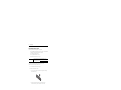
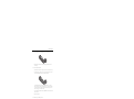
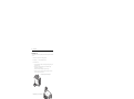
Installation Instructions
Memory Modules
Catalog Number 6189V-1GDDR2, 6189V-512MDDR2
Topic
Page
Important User Information
2
Electrostatic Discharge (ESD) Precautions
3
Voltage Precaution
3
Before You Begin
4
Required Tools
4
Pre-installation Procedure
4
Remove the Side Cover
5
Install the Memory Modules
5
Memory Module Installation Guidelines
6
Post-installation Procedure
9
Additional Resources
9
About This Publication
This publication provides pre- and post-installation information and procedures on how to
install memory modules in the VersaView 750R and 1450R non-display computers.
Publication 6177R-IN003B-EN-P - November 2009
2
Memory Modules
Important User Information
Solid state equipment has operational characteristics differing from those of electromechanical equipment.
Safety Guidelines for the Application, Installation and Maintenance of Solid State Controls (Publication
SGI-1.1 available from your local Rockwell Automation sales office or online at
http://www.literature.rockwellautomation.com) describes some important differences between solid state
equipment and hard-wired electromechanical devices. Because of this difference, and also because of the
wide variety of uses for solid state equipment, all persons responsible for applying this equipment must
satisfy themselves that each intended application of this equipment is acceptable.
In no event will Rockwell Automation, Inc. be responsible or liable for indirect or consequential damages
resulting from the use or application of this equipment.
The examples and diagrams in this manual are included solely for illustrative purposes. Because of the many
variables and requirements associated with any particular installation, Rockwell Automation, Inc. cannot
assume responsibility or liability for actual use based on the examples and diagrams.
No patent liability is assumed by Rockwell Automation, Inc. with respect to use of information, circuits,
equipment, or software described in this manual.
Reproduction of the contents of this manual, in whole or in part, without written permission of Rockwell
Automation, Inc., is prohibited.
Throughout this manual, when necessary, we use notes to make you aware of safety considerations.
WARNING
IMPORTANT
ATTENTION
Identifies information about practices or circumstances that can cause an explosion in
a hazardous environment, which may lead to personal injury or death, property
damage, or economic loss.
Identifies information that is critical for successful application and understanding of
the product.
Identifies information about practices or circumstances that can lead to personal injury
or death, property damage, or economic loss. Attentions help you to identify a hazard,
avoid a hazard, and recognize the consequences.
SHOCK HAZARD
Labels may be located on or inside the equipment, for example, a drive or motor, to
alert people that dangerous voltage may be present.
BURN HAZARD
Labels may be located on or inside the equipment, for example, a drive or motor, to
alert people that surfaces may be dangerous temperatures.
Publication 6177R-IN003B-EN-P - November 2009
Memory Modules
3
Electrostatic Discharge (ESD) Precautions
ATTENTION
Electrostatic discharge (ESD) can damage static-sensitive devices or
microcircuitry. Observe proper packaging and grounding techniques to
prevent damage. Follow the precautions listed below.
• Transport the computer and replacement parts in static-safe containers such as
conductive tubes, bags, or boxes.
• Keep electrostatic-sensitive parts in their containers until they arrive at static-free
stations.
• Cover workstations with approved static-dissipating material. Use a wrist strap
connected to the work surface and properly grounded (earthed) tools and equipment.
• Keep work area free of nonconductive materials, such as ordinary plastic assembly
aids and foam packing.
• Avoid touching pins, leads, or circuitry.
• Always hold components with a printed circuit board (PCB) by its edges and lay it
with the assembly-side down.
Voltage Precaution
The computers contain line voltages. Disconnect all power to the computer before you install
or remove system components.
SHOCK HAZARD
Disconnect power from the computer before removing components.
Failure to disconnect power could result in severe electrical shock and/or
damage the computer.
Publication 6177R-IN003B-EN-P - November 2009
4
Memory Modules
Before You Begin
Review the specifications of a new component before installing it to make sure it is
compatible with the computer. Record the model and serial number, and any other pertinent
information of new components for future reference.
ATTENTION
To avoid voiding your product warranty, use only Rockwell Automation
Allen-Bradley-approved replacement parts and accessories.
Required Tools
These tools are required for installing a memory module.
• #2 Phillips screwdriver
• Antistatic wrist strap
• Scissors (for cutting cable ties)
Pre-installation Procedure
IMPORTANT
When installing hardware requiring access to internal components, we
recommended that you first back up all computer data to avoid loss.
ATTENTION
Make sure to read and understand the entire installation/removal
procedure first, before you begin configuring the computer hardware.
Perform this pre-installation procedure before removing the side cover and/or accessing a
hardware component.
1. Turn off the computer and all the peripherals connected to it.
2. Disconnect power from the computer to avoid exposure to high energy levels.
If necessary, label each one to expedite reassembly.
3. Disconnect telecommunication cables to avoid exposure to shock hazards from
ringing voltages.
Publication 6177R-IN003B-EN-P - November 2009
Memory Modules
5
Install the Memory Modules
The motherboard of the computer has two DIMM slots that support up to 2 GB maximum
system memory.
Remove the Side Cover
To maintain, install, or upgrade computer components, excluding the hard disk drive (HDD),
you must first remove the side cover.
Follow this procedure to remove the side cover:
1. Perform the pre-installation procedure.
2. Unfasten the side cover from the system chassis by removing the two screws located
on the rear edge of the side cover.
3. Slide the side cover back about 1.5 cm (0.5 in.), then pull the panel away from the
chassis.
Removing the Side Cover on the 750R Computer
XX.XXXXX.XX
XX
.XX
XX
X.X
X
Removing the Side Cover on the 1450R Computer
Publication 6177R-IN003B-EN-P - November 2009
6
Memory Modules
Memory Module Installation Guidelines
Follow these guidelines when adding memory to the computers.
• Use only standard unbuffered memory modules that conform to both PC2-4300 and
Serial Presence Detect (SPD) compliance industry standards.
• Use only DDR2 type memory modules.
• Use only gold-plated lead memory modules.
• Always handle the memory modules by its edges.
IMPORTANT
We recommend that you use only qualified Allen-Bradley memory
modules. Refer to the Web site http://www.ab.com/industrialcomputers
for a list of qualified accessories.
To install an additional memory module, proceed to Step 3 of this section.
Follow these procedures to replace a memory module:
1. Locate the memory module you want to replace.
2. Remove the selected memory module.
a. Use scissors to clip the cable tie that secures the retaining latches holding the
selected memory module.
b. Completely open the retaining latches securing the memory module.
This forces the module up in the slot and makes it easier to remove.
Publication 6177R-IN003B-EN-P - November 2009
Memory Modules
7
c. Gently pull the memory module upward to remove it from its slot.
d. Place the memory module on a static-dissipating work surface or inside an
antistatic bag.
3. Install the new memory module.
a. Hold the memory module by its edges as you remove it from its anti-static bag.
b. Orient the module so that the notch on its bottom edge aligns with the keyed
surface of the DIMM slot, and then press it fully into the slot.
The DIMM slots are designed to ensure proper installation. If you insert a
memory module but it does not fit easily into the slot, you may have inserted it
incorrectly. Reverse the orientation of the module and insert it again. The slot
latches must engage to secure the module.
c. Fasten a replacement cable tie around the DIMM slot latches to fully secure the
memory module.
d. Replace the side cover.
4. Perform the post-installation procedure.
Publication 6177R-IN003B-EN-P - November 2009
8
Memory Modules
Reinstall the Cover
After completing any removal or replacement procedure of internal components, reinstall the
side cover.
1. Make sure the computer is in its normal upright position.
2. Perform steps 1…3 of the post-installation procedure.
3. Reinstall the side cover.
a. Position the lower edge of the side cover at an angle to the hinge tabs along the
bottom of the chassis.
b. Rest the cover on the hinge tabs, tilting it up until it engages the locking
mechanism at the top of the chassis.
c. Slide the cover towards the front panel to position it into place.
e. Secure the cover once it is attached to the chassis by replacing the two screws
located on the rear edge of the side cover.
Reinstalling the Side Cover on the 750R Computer
XX.XXXXX.XX
Reinstalling the Side Cover on the 1450R Computer
XX
.XX
XX
X.X
X
Publication 6177R-IN003B-EN-P - November 2009
Memory Modules
9
Post-installation Procedure
Perform this post-installation procedure after installing or removing a hardware component.
1. Make sure all components are installed according to the described step-by-step
instructions.
2. Make sure that no loose tools or parts are left inside the computer.
3. Reinstall any expansion boards, peripherals, board covers, and system cables that have
previously been removed.
4. Reinstall the side cover if necessary.
5. Connect all external cables and power to the computer.
6. Press the power switch to turn on the computer.
Additional Resources
For more information on the VersaView Light Industrial non-display computers, refer to the
user manual, publication 6177R-UM001.
You can download these publications and translated versions of the user manual and
installation instructions from the Web site http://www.rockwellautomation.com/literature.
Publication 6177R-IN003B-EN-P - November 2009
10
Memory Modules
Publication 6177R-IN003B-EN-P - November 2009
Memory Modules
11
Publication 6177R-IN003B-EN-P - November 2009
Rockwell Automation Support
Rockwell Automation provides technical information on the Web to assist you in
using its products. At http://support.rockwellautomation.com, you can find
technical manuals, a knowledge base of FAQs, technical and application notes,
sample code and links to software service packs, and a MySupport feature that you
can customize to make the best use of these tools.
For an additional level of technical phone support for installation, configuration,
and troubleshooting, we offer TechConnect Support programs. For more
information, contact your local distributor or Rockwell Automation representative,
or visit http://support.rockwellautomation.com.
Installation Assistance
If you experience a problem with a hardware module within the first 24 hours of
installation, please review the information that's contained in this manual. You can
also contact a special Customer Support number for initial help in getting your
module up and running.
United States
1.440.646.3223
Monday – Friday, 8am – 5pm EST
Outside United
States
Please contact your local Rockwell Automation representative for any
technical support issues.
New Product Satisfaction Return
Rockwell tests all of its products to ensure that they are fully operational when
shipped from the manufacturing facility. However, if your product is not
functioning, it may need to be returned.
United States
Contact your distributor. You must provide a Customer Support case number
(see phone number above to obtain one) to your distributor in order to
complete the return process.
Outside United
States
Please contact your local Rockwell Automation representative for return
procedure.
Allen-Bradley, Rockwell Automation, and VersaView are registered trademarks of Rockwell Automation, Inc.
Trademarks not belonging to Rockwell Automation are the property of their respective companies.
Publication 6177R-IN003B-EN-P - November 2009
Supersedes Publication 6177R-IN003A-EN-P - August 2006
PN 41061-378-01(2)
Copyright © 2009 Rockwell Automation, Inc. All rights reserved. Printed in China.