1
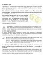
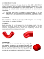
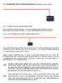
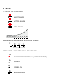
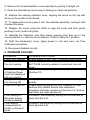
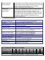
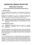
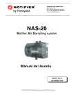
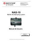
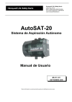
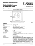
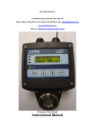
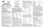
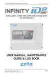
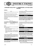
LASER ASPIRATED SMOKE DETECTOR LASD1 (Single Channel) INSTALLATION, OPERATION & MAINTENANCE INSTRUCTIONS (CE) 1 INTRODUCTION The LASD1 utilises one or two high-sensitivity laser point detectors in an aspirated enclosure. This allows for a large area of coverage using sampling holes in place of traditional point detectors. The unit can be set up in three different detector configurations – Single, Redundant & Double-Knock with three levels of alarm which can be set according to application. A high performance aspirator and flow sensing system ensure a constant, monitored airflow which can be displayed on a 10 element bargraph with adjustments for high and low flow thresholds. Faults and alarms are reported via separate volt-free contacts. The LASD1 can be set-up using integrated programming keys or via the USB interface port with the Windows™ based Configuration program. The program also provides access to the events data that are logged within the unit. CAUTION! THE LASD1 SYSTEM HAS BEEN INDEPENDENTLY TESTED AND CERTIFIED TO CEA4022 AND MUST BE INSTALLED IN STRICT COMPLIANCE WITH THE INSTRUCTIONS BELOW IF THE CERTIFICATION IS TO BE MAINTAINED 2 SYSTEM INSTALLATION WARNING! THIS EQUIPMENT MUST BE INSTALLED BY A QUALIFIED INSTALLER IN ACCORDANCE WITH ALL LOCAL AND NATIONAL REGULATIONS Remove the transparent cover using the special tool provided to unscrew the tamper proof fasteners. Use the template provided to accurately position the holes then secure the unit to a suitable surface (wall or ceiling) through the 4 corner fixing points. Ensure that the correct fasteners are used for the type of surface that the unit is mounted on. 3 WIRING For correct operation of the unit it is essential that the case is fully sealed so that air can only be pulled into the system through the aspirating pipe. For this reason, all wiring must pass through the cable seals provided and no additional holes should be made. In order to pass a cable through a seal it is necessary to make a small hole in the centre of the seal with a pointed implement (e.g. small screwdriver) and then force the cable through the hole into the unit. The small hole will expand to accommodate any cable diameter from 4 to 10mm and then provide an airtight seal. In order to gain access to the main circuit board for connection of the wiring it is necessary to remove the display/detector mounting board which is held in place by the clear top cover. Care should be taken when removing the board to ensure that the ribbon cable on the underside is not strained. The ribbon cable may be removed from the connector on the underside of the board to allow the board to be fully removed. WARNING! TO PREVENT RISK OF ELECTRIC SHOCK, OR POSSIBLE INJURY FROM THE ROTATION OF THE HIGH PERFORMANCE FAN, THE SYSTEM SHOULD BE ISOLATED FROM THE SUPPLY WHEN THE TOP COVER IS REMOVED All connections to the main circuit board are to pluggable terminals that can accommodate wire sizes up to 2.5mm2. 3.1 FIELD CONNECTIONS 3.1.1 BATTERY +24V 0V EXTERNAL RESET + - BAT FUSE FIRE 2 NO COM NC ACTION 2 NO COM NC BATTERY The LASD1 unit is designed to run from a nominal 24V DC supply. The supply should be connected to the 2 way ‘BATTERY’ connector on the main circuit board ensuring that the wires are correctly orientated. It is recommended FAULT 2 NO COM NC that the wires should be a minimum size of 16 x 0.25mm (18AWG), or larger if the supply is further than 5m from the system. A ferrite core is provided for EMC compliance. This should be fitted to the power supply wiring inside the unit as shown above. The power requirements are dependant on the fan speed selected – see table in Section 10.2 for details. 3.1.2 ACTION 2 The volt-free relay contacts ACTION will change state when the pre-alarm level for the channel has been exceeded. The terminals provide for Normally Open (NO) or Normally Closed (NC) operation 3.1.3 FIRE 2 The volt-free relay contacts FIRE will change state when the alarm level for the channel has been exceeded. The terminals provide for Normally Open (NO) or Normally Closed (NC) operation 3.1.4 FAULT 2 In the event of a fault condition, the Fault relay will change state. The terminals provide for Normally Open (NO) or Normally Closed (NC) operation. NO/NC REFERS TO THE UN-POWERED STATE OF THE RELAYS. UNDER NORMAL, NON FAULT, CONDITIONS NO IS CLOSED AND NC IS OPEN 3.1.5 EXTERNAL RESET The application of a nominal 24V DC signal to these pins forces the unit into Reset clearing all faults and alarms. 3.1.6 USB CONNECTOR A type ‘B’ USB connector is provided on the bottom of the unit to allow connection to a PC using a standard USB cable (not supplied). This communication port allows for configuration or downloading of logged data using the Windows™ based Configuration Program. The connector is protected with a screw-fit cover and care should be taken to ensure that the cover is securely fastened when the connector is not in use to prevent the ingress of dirt or moisture. The Configuration Program and manual can be found on the CD-ROM supplied with the LASD1 together with the necessary USB drivers. 4 DETECTORS The LASD1 is supplied with a single laser point detector as standard with the option for a second detector – order code LPDET - for Redundant or DoubleKnock operating modes. The detectors interface directly with the LASD1 circuit. This allows the detectors status and analogue smoke level output to be read and interpreted by the LASD1 processor. Each detector is identified with a 2 digit address which is set on switches on the underside of the top detector part. The addresses should be left to the factory pre-set values of 1 for the default detector in the channel/detector 1 position and address 2 for the optional, second detector in the channel/detector 2 position. CAUTION! IF THE DETECTORS ARE REMOVED FOR MAINTENANCE THEY MUST BE FITTED IN THE POSITIONS DESCRIBED ABOVE – FAILURE TO DO SO MAY RESULT IN FALSE REPORTING IN THE EVENT OF A FAULT OR FIRE 5 PIPE INSTALLATION A simple guide to pipe installation follows with examples of standard configurations and should contain all the information required for simple installations based on the standard configurations. REFER TO THE PIPE INSTALLATION MANUAL (INCLUDED ON CD-ROM) FOR DETAILED INFORMATION AND MORE PRACTICAL EXAMPLES THE PIPE SIMULATION UTILITY (INCLUDED ON CD-ROM) SHOULD BE USED TO CALCULATE TRANSPORT TIMES, DILUTION EFFECTS ETC. FOR ALL INSTALLATIONS BEYOND THE SCOPE OF THIS GUIDE Use 25mm (or ¾”) Red ABS pipe with sampling point holes drilled along its length. The pipe run is terminated with an end cap that has a hole drilled in its centre. The position of each individual sampling point should be in accordance with the rules for the positioning of point detectors. It is important to note that the concentration of smoke on an individual sample point will be diluted by the clean air from the other sample points and the end cap hole. 5.1 PIPE SPECIFICATION For CEA4022 compliance, the pipe should be Red ABS to EN 50086-1 (Crush 1, Impact 1, Temp 33) with a nominal diameter of 25mm (or ¾”). The sample pipe is normally supplied in 3 metre lengths and is cut as required and joined by solvent welded sockets (permanent), or socket unions (removable). THE LASD1 INLET PORT IS TAPERED TO ALLOW A PUSH FIT OF THE SAMPLING PIPE. THE PIPE SHOULD BE CUT SQUARELY TO ENSURE A GOOD, AIRTIGHT SEAL. SOLVENT ADHESIVE SHOULD NOT BE USED FOR THIS JOINT 5.2 FIXINGS The normal fixing methods are pipe clips, saddle clamps or even tie wraps. Fixing centres are typically 1.5m apart. 5.3 BENDS Bends are either 45 or 90 degrees. For the 90-degree bends it is very important that swept bends are used and not sharp elbows, as this will introduce unacceptable pressure losses, and significantly increase the response times from holes beyond the bend. 5.4 END CAP The end of the pipe is terminated with a cap, usually with a hole drilled in its centre. If the end cap is not used, then practically no air will be drawn through the side holes. If the end cap does not have a hole then the contributions from the side holes will tend to be very unbalanced. The end cap can be considered a sampling point if required. 5.5 HOLES The sampling pipe is perforated with sampling holes and can either be predrilled or drilled in situ. Care should be taken to avoid swarf entering the pipe. Always blow compressed air through the pipe after drilling to clear any debris before final connection to the equipment. In standard installations, with pipe hanging from ceiling, the holes should be placed underneath, so the smoke can easily rise up into the holes. 5.6 EXHAUST In most installations the exhaust should be left open but there are some circumstances when it may be necessary to connect pipe to the exhaust port to divert the exhaust away from the location of the unit e.g. to reduce noise, reduce risk of interference/deliberate obstruction, improved environmental protection etc. Pipe of the same specification as the sample runs should be used and its length limited to a maximum of 10m to avoid significant reduction in the air flow. Care should be taken to position the new exhaust outlet where it cannot be accidentally or deliberately blocked. 5.7 FILTERS The sampled air is passed through a 2 stage filter – replacement order code FL55 - before entering the detector chamber. As standard, the filtration should be sufficient for all but extremely dusty conditions where a Harsh Environment Filter - order code FLU1 (3/4”) / FLU2 (25mm) - should be fitted between the unit and the first sampling point. 5.8 STANDARD PIPE CONFIGURATIONS (Drawings not to scale) 5.8.1 SINGLE PIPE CONFIGURATION Pipe length 50m maximum with up to 13 x 3mm sampling points and 6mm end hole. Pipe length 75m maximum with up to 11 x 3mm sampling points and 6mm end hole. 5.8.2 TWO PIPES WITH TEE CONFIGURATION Pipe length 100m maximum (50m per branch) with up to 11 x 3mm sampling points and 6mm end hole per branch. Distance from unit to Tee must be <= 1m and pipes should be balanced i.e. equal length and equal number of holes. Alarm (Fire) threshold set to level 3 and fan speed set to 9 for all configurations with maximum pipe length/number of sample holes. The use of additional bends as described in Section 5.3 will have a minimal affect on performance – i.e. response time. STATED LIMITS ARE BASED ON CEA 4022 CERTIFICATION TESTING. SIGNIFICANT REDUCTIONS IN PIPE LENGTH MAY ALLOW THE FAN SPEED TO BE REDUCED AND/OR NUMBER OF HOLES INCREASED. RESULTS OF SUCH CHANGES, OR NON STANDARD/UNBALANCED CONFIGURATIONS, SHOULD BE VERIFIED WITH THE PIPE SIMULATION UTILITY. PIPE LENGTHS UP TO 100m (100m + 100m Tee) MAY BE USED IF CEA 4022 CERTIFICATION IS NOT A REQUIREMENT. DESIGNS SHOULD BE VERIFIED WITH THE PIPE SIMULATION UTILITY TO ENSURE THAT PERFORMANCE IS SUITABLE FOR THE INTENDED APPLICATION. 6 SETUP 6.1 DISPLAY FUNCTIONS ALERT ALARM ACTION ALARM FIRE ALARM BARGRAPH of SMOKE LEVEL or AIRFLOW SPEED AIRFLOW OK - HIGH AIRFLOW - LOW AIRFLOW SMOKE DETECTOR FAULT (1 PER DETECTOR) ISOLATE POWER ON GENERAL FAULT MAINS FAILURE (Mains PSU Option Only) BATTERY LOW (Mains PSU Option Only) FAN FAULT RESET UNLOCK CODE ENTRY M ODE DETECTOR OPERATING MODE 6.2 USER FUNCTIONS Press and hold SELECT and CHANGE keys simultaneously until the sounder beeps to initialize function selection. Press and release SELECT key to sequentially step through functions. Press and release CHANGE key to modify setting. The relevant LED flashes continuously to indicate the function selected. 1) Enter 3 digit access code - 510. Each number must be selected in turn i.e. press CHANGE six times to illuminate the number 5 LED on the display then press SELECT. (CODE and UNLOCK LEDs flash on successful entry). 2) To RESET the unit press CHANGE when the LED is flashing. 3) ISOLATE detector (ISOLATE LED flashes when not set – steady illumination when set). 4) Set fan speed (POWER LED flashes). Bargraph display indicates fan speed 0-9. 5) Set SENSITIVITY of bar graph to changes in airflow velocity (FLOW OK flashes). 0 = Minimum Sensitivity, 9 = Maximum Sensitivity. 6) Select the BARGRAPH LED segment above which the FLOW HIGH LED will be illuminated (FLOW HIGH flashes). 7) Select the BARGRAPH LED segment below which the FLOW LOW LED will be illuminated (FLOW LOW flashes). 8) Set smoke detector ALERT alarm threshold (ALERT LED flashes) 9) Set smoke detector ACTION alarm threshold (ACTION LED flashes) 10) Set smoke detector FIRE alarm threshold (FIRE LED flashes) 11) Select Detector MODE 1, 1or2, 1&2 (See below for detailed description of Modes) 12) Set SOUNDER On or Off. If the buzzer is sounding long beeps, this signifies it is on. If it sounds short beeps, this signifies it is in the off setting. 13) Set/Unset Alarm Latching function (SMOKE DETECTOR FAULT LED flashes). Bargraph display indicates alarm latching status – 0 = Non Latching, 1 = Latching. 14) Calibrate flow sensors (FAN FAULT LED flashes). CHANGE key must be pressed for at least 2 seconds to initiate the flow calibration process. FAN and POWER LEDs flash to indicate calibration in progress. Fan is temporarily stopped as part of the calibration process. The system will reset and revert to normal operating mode when flow calibration is completed. Pressing the SELECT key for longer than 1 second when the unit is unlocked will cause the unit to revert to normal operating mode. Momentarily pressing the SELECT or CHANGE key when the unit is locked (UNLOCK LED is off) causes the unit to display the airflow on the bargraph. The display reverts back to the smoke level reading after a few seconds. 6.2.1 DETECTOR MODE The LASD1 has three different modes which can be set to provide different types of coverage. Mode 1 - 1 Only – Single Detector. The display shows the detector reading and the unit reports Alert, Action and Fire conditions when the pre-set thresholds are exceeded. Mode 2 - 1 or 2 – Two Detectors working independently (Redundancy). The display shows the higher of the two detector readings and the unit reports Alert, Action and Fire conditions when the pre-set thresholds are exceeded on either detector. This mode allows for continued operation in the event of a problem with one of the detectors. Mode 3 - 1 & 2 – Two detectors working together (Double Knock). The display shows the lower of the two detector readings and the unit reports Alert, Action and Fire conditions when the pre-set thresholds are exceeded on BOTH detectors. MODE 3 IS NOT PERMITTED IN A VdS APPROVED INSTALLATION The LASD1 is supplied with a single detector as standard. Mode 2 or 3 operation is dependant upon the purchase of an optional, second detector. Selection of Modes 2 or 3 with a single detector fitted will result in a Smoke Detector Fault being reported. 6.3 SET-UP NOTES The Fan Speed, Flow Limits and Flow Sensitivity need to be set for each installation prior to Flow Calibration and testing. It is not possible to provide the settings for all possible installations but the following guidelines should assist in the commissioning of the unit. 6.3.1 FAN SPEED The Fan Speed should be set as high as possible to achieve the fastest transport time from the sampling point to the detectors, this is especially important for longer pipe lengths and for installations that must conform to the requirements of CEA4022 (see Section 5.8). There is, however, a balance to be achieved between performance and the units power requirements and reference should be made to the current consumption figures in the specifications prior to setting this value. Fan speeds 3 and below should not be used for standard configurations. 6.3.2 FLOW SENSITIVITY This setting determines the systems responsiveness in reporting blocked sampling points or broken pipes. The number of sampling points and fan speed are the main factors to consider for this setting. The following table shows typical settings for a variety of standard fan speed/hole quantity combinations. Other speed/hole combinations should be verified by testing during commissioning. 6.3.2.1 TYPICAL FLOW SENSITIVITY SETTINGS PIPE SETUP (all 50m lengths unless otherwise stated) 13 x 3mm Sampling Holes, 1 x 6mm End Hole 8 x 3mm Sampling Holes, 1 x 6mm End Hole 4 x 3mm Sampling Holes, 1 x 6mm End Hole 1 x 5mm Sampling Hole, 1 x 5mm End Hole 1 x 8mm End Hole 1 x 8mm End Hole (10m Pipe) RECOMMENDED FAN SPEEDS 9 6-9 6-9 6-9 5-9 3-9 FLOW SENSITIVITY 9 9 7 5 2 1 7 TESTING TESTING SHOULD ONLY BE CARRIED OUT BY QUALIFIED PERSONNEL. BEFORE UNDERTAKING ANY TESTING ENSURE THAT THE PROPER AUTHORITIES HAVE BEEN INFORMED AND THAT THE UNIT HAS BEEN ISOLATED FROM THE FIRE CONTROL PANEL IF NECESSARY TO PREVENT UNWANTED ALARMS 7.1 DETECTORS With the unit powered up and top cover removed the detectors can be tested for functionality using a low concentration smoke source or aerosol point detector spray. The detector can also be tested by placing a magnet against the test marker at the 7 o’clock position on the detector rim. This test electronically simulates the effect of smoke in the sensing chamber. 7.2 SYSTEM The installed system must be checked with the top cover securely fitted. As a minimum, smoke should be introduced to the furthest sampling point from the LASD1 unit on each branch of the pipe. The choice of smoke source is dependant on the installation but in all cases the smoke must be present for the duration of the test – aerosol sprays for point detectors do NOT work on aspirated systems. If it is possible to get close to the sampling point then a basic, functional check can be carried out with smoke matches or lighted taper etc. but for measurable performance tests then refer to Appendix A of the BFPSA Code of Practice for Aspirating Systems to select the appropriate test for the installation. 8 MAINTENANCE With normal use, the filter elements will eventually become contaminated with dust particles. It is recommended that the filter elements – order code FL55 - are replaced and detectors cleaned every six months (more frequently for dirty environments). MAINTENANCE SHOULD ONLY BE CARRIED OUT BY QUALIFIED PERSONNEL. BEFORE CARRYING OUT ANY MAINTENANCE, NOTIFY THE PROPER AUTHORITIES AND ISOLATE UNIT FROM THE FIRE CONTROL PANEL TO PREVENT UNWANTED ALARMS 1. Remove power from the unit. 2. Remove the transparent cover using the special tool provided to unscrew the tamper proof fasteners. 3. Lift out the foam filter elements from the filter tube (tweezers or long nosed pliers are recommended for this operation). 4. Fit a new filter element set ensuring that the coarse grade filter is inserted into the tube first. Care should be taken to ensure that the filters are not compressed during fitting and that the fine filter is positioned flush with the top of the filter tube. 5. Remove the detectors from their mounting bases by twisting anticlockwise. 6. Remove the detector cover by prying away the four side tabs with a smallbladed screwdriver, and then pulling the cover from the base. 7. Vacuum the screen carefully without removing it. If further cleaning is required continue with Step 8, otherwise skip to Step 12. 8. Remove the screen/chamber cover assembly by pulling it straight out. 9. Clean the chamber by vacuuming or blowing out dust and particles. 10. Replace the sensing chamber cover, aligning the arrow on the top with arrow on the printed circuit board. 11. To replace the screen, place it over the chamber assembly, turning it until it snaps into place. 12. Replace the cover using the LEDs to align the cover and then gently pushing it until it locks into place. 13. Reinstall the detectors onto their bases ensuring that they are in the correct position i.e. detector set to address 1 fitted to detector 1 position. 14. Refit the transparent cover, apply power to unit and carry out Flow Calibration procedure. 15. Reconnect disabled circuits. 9 PROBLEM SOLVING PROBLEM Power light flashing No lights on display. Fan not running General Fault Light & Flashing Power Light only displayed. Fan not running. No lights on display. Fan running OK. Flow HI/LO light on Flow reading on Bargraph display moves erratically. Flow reading unresponsive to broken or blocked pipes POSSIBLE SOLUTIONS Ensure supply to BATTERY connector within limits. Ensure supply leads correctly orientated. Ensure that BAT FUSE correctly seated in socket and fuse not blown. Ensure that supply voltage is within specified limits (Section 10) Ensure ribbon cable fully seated into main & display boards. Ensure sampling pipes correctly installed, lid fitted and box fully sealed. Ensure flow calibration procedure has been carried out (Section 6.2). Ensure that filters are clean (Section 8). Decrease Flow sensitivity setting and re-calibrate air flows (Section 6.2). Increase Flow sensitivity setting and re-calibrate air flows (Section 6.2). Smoke Detector Fault indicated Ensure that correct address has been set (Section 4). Ensure detector fully seated into base. Ensure correct Mode setting selected (Section 6.2.1). Ensure detector optics are clean (Section 8). Ensure that sampling pipe installed correctly and is undamaged (Section 5). Ensure unit cover correctly fitted. Ensure that holes and pipe length do not exceed limits and the fan speed is sufficient (Section 5.8). Ensure that recommended test method is used (Section 7). Ensure detector addresses are set correctly (Section 4). Detector(s) unresponsive to smoke tests 10 SPECIFICATIONS Number of Detectors 1 or 2, Laser based Analogue Addressable Filtration 2 Stage cartridge dust particle filter Flow Monitoring Thermal device, high and low thresholds. 10 element bar graph indication. Supply Voltage 18-30V DC (24V DC Nominal) Maximum Supply Current 350mA @24V DC with no aspirating pipe. See table below for typical Currents/Fan Speeds. Maximum Tube Length 100 + 100 metres in Tee Configuration (75m single or 50 + 50m Tee CEA 4022) Environmental Protection IP65 with exhaust fitted (IP53 without) Operating Temperature -10 to 50ºC Operating Humidity 10 to 95% RH (non-condensing) Approvals CEA 4022 by VdS (G206066) CE Certification EN61000-6-3:2001(+A11:2004) (EMC) EN60950-1:2006 (Safety) 10.1 DETECTOR SENSITIVITY VALUES Bargraph Value 1 2 3 4 5 6 7 8 1 Obscuration %/m 0.03 0.06 0.13 0.31 0.73 1.24 1.93 2.63 Obscuration %/ft 2 0.02 0.03 0.05 0.10 0.20 0.50 1.00 1.50 1) Based on tests to EN54-7 2) Based on tests to UL268 9 3.33 2.00 10.2 TYPICAL CURRENT/FAN SPEED Bargraph Value 0 1 2 3 4 5 6 7 8 Fan Speed 1 2 3 4 5 6 7 8 9 Current (mA) 110 120 130 150 170 190 220 235 265 9 10 300 Typical current consumption figures for different fan speeds. Results are based upon a LASD2 installation with 10m of standard, 25mm aspirating pipe per channel. The unit was powered from a 24V supply. WEEE DIRECTIVE 2002/96/EC (Waste Electrical and Electronic Equipment) The symbol shown is marked on this product to indicate that it must not be disposed of with other waste. Instead, it is the user’s responsibility to dispose of their waste equipment by handing it over to a designated collection point for the recycling of waste electrical and electronic equipment. The separate collection and recycling of your waste at the time of disposal will help to conserve natural resources and ensure that it is recycled in a manner that protects human health and the environment. For more information about where you can drop off your waste equipment for recycling, please contact your local city office, your household waste disposal service or where you purchased the product. GLT Exports Limited, Detection House, 72-78 Morfa Road, Hafod, Swansea, SA1 2EN, United Kingdom Telephone +44 (0)1792 455175 Fax +44 (0)1792 455176 e-mail address: [email protected] web site: www.zeta-alarms.co.uk LASD1 Manual (CE) – Issue 10.0 Part No. 09-0103-10