1
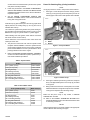
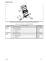
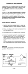
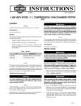
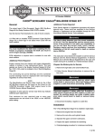
-J04992
REV. 2009-07-07
SCREAMIN' EAGLE PRO 11:1 COMPRESSION, 3.875 INCH BORE
PISTONS
GENERAL
NOTE
NOTES
Always check piston-to-valve clearance when using non-stock
camshafts.
All dimensions listed on these instructions are in inches.
ECM recalibration is required, which can be performed with
the Screamin' Eagle Race Tuner Kit (Part Number 32107-01F).
See a Harley-Davidson dealer.
Re-jetting and/ or re-timing of the engine may be required to
realize the full potential of this performance product.
High compression piston applications require installation of
appropriate compression release in cylinder heads.
The pistons in this kit have an Electroless Nickel plating in the
piston pin bores and require the use of a non-plated piston pin
only (22304-08).
Kit Numbers
21916-08A, 21928-08A
The rider's safety depends upon the correct installation
of this kit. Use the appropriate service manual procedures.
If the procedure is not within your capabilities or you do
not have the correct tools, have a Harley-Davidson dealer
perform the installation. Improper installation of this kit
could result in death or serious injury. (00333a)
Table 1. Kits
Kit
NOTE
Application
21928-08A
Standard, 3.875 in. (front & rear)
21916-08A
+0.010 (front & rear)
This instruction sheet references Service Manual information.
A Service Manual for your model motorcycle is required for
this installation and is available from a Harley-Davidson Dealer.
Kit Contents
See Table 4, and Figure 3.
Models
INSTALLATION
These kits fit Harley-Davidson Twin Cam models equipped
with the following items:
•
Cylinder heads: Screamin' Eagle Pro MVA, 110+ or ACR
Performance cylinder heads.
•
Cylinders: Screamin' Eagle Pro 3-7/8" Big Bore cylinders.
•
Flywheels: Screamin' Eagle Pro 4-3/8" stroke flywheels
or '07-later original equipment 4-3/8" stroke flywheel
assembly.
NOTE
This engine-related performance part is intended for high-performance or racing applications and is not legal for sale or use
on pollution-controlled motor vehicles. This kit may reduce or
void the limited vehicle warranty. Engine-related performance
parts are intended for the experienced rider only.
To prevent accidental vehicle start-up, which could cause
death or serious injury, disconnect battery cables (negative
(-) cable first) before proceeding. (00307a)
Disconnect negative (-) battery cable first. If positive (+)
cable should contact ground with negative (-) cable connected, the resulting sparks can cause a battery explosion,
which could result in death or serious injury. (00049a)
1.
Refer to the Service Manual and follow the instructions
given to remove the seat and disconnect the battery
cables, negative cable first.
Additional Parts Required
You must recalibrate the ECM when installing this kit.
Failure to properly recalibrate the ECM can result in severe
engine damage. (00399b)
-J04992
When servicing the fuel system, do not smoke or allow
open flame or sparks in the vicinity. Gasoline is extremely
flammable and highly explosive, which could result in
death or serious injury. (00330a)
2.
Refer to the ENGINE: STRIPPING MOTORCYCLE FOR
SERVICE and TOP END OVERHAUL, DISASSEMBLY
1 of 3
3.
4.
sections of the Service Manual for cylinder head, cylinder
and piston removal procedures.
Piston Pin Retaining Ring (Circlip) Installation
Follow the procedures in the ENGINE: SUBASSEMBLY
SERVICE AND REPAIR, TOP END/ CYLINDER/ UPPER
CONNECTING ROD sections of the Service Manual for
inspection of parts.
Circlip gap must be at 12:00 or 6:00 position when installed.
NOTE
7.
See the ENGINE: SUBASSEMBLY SERVICE AND
REPAIR, CYLINDER section of the Service Manual for
boring and honing instructions.
See Figure 1. Insert the open end of the circlip (1) into the
notch (3) on the groove (2) around the piston pin boss so
that the gap is at the 12:00 or 6:00 position when installed.
is02626
3
1
NOTES
Install the top ring (barrel-faced) and second ring (taper-faced
Napier) with the "N" marking facing up. Oil ring rails can be
installed either side up.
The 4.060 inch cylinder base gaskets and cylinder head gaskets included in the kit eliminate the need for O-rings (11273).
Do not use O-rings on cylinder dowels or cylinder spigots.
2
When installing new base gasket, install with the embossed
side down and the concave side up.
Piston dimensions to be measured 0.281 inches above the
lowest part of the skirt.
5.
6.
1. Circlip
2. Notch
3. Groove
The pistons in this kit are front and rear specific. Install
the piston marked "FRONT" in the front cylinder with the
arrow pointing towards the front of the engine. Install the
piston marked "REAR" in the rear cylinder with the arrow
pointing towards the front of the engine.
Figure 1. Circlip and Piston
is02627
2
Refer to the ENGINE: TOP END OVERHAUL, ASSEMBLY
section of the Service Manual for piston, cylinder and cylinder head installation procedures.
1
Table 2. Specifications
Piston:
Clearance (in.)
Fit in cylinder (Loose)
0.0015-0.0025
Piston pin fit (Loose)
0.0003-0.0008
Top Ring End Gap
Second Ring End Gap
Oil Control Ring Rail Gap
0.012-0.020
0.016-0.024
0.007-0.030
Top Ring Side Clearance
Second Ring Side Clearance
Oil Control Ring Side Clearance
0.0015-0.0029
0.0015-0.0029
0.0010-0.0072
1. Thumb orientation
2. Circlip 85% seated
Figure 2. Install Circlip
8.
See Figure 2. Position your thumb (1) as shown, and press
firmly until approximately 85% of the circlip (2) is seated
in the groove.
9.
Being careful not to scratch or mar the piston, use a smallbladed screwdriver to wedge the circlip into the remainder
of the groove. Repeat for the remaining circlips.
Table 3. Service Wear Limits
Fit in Cylinder (Loose)
Wear Limit (in.)
Fit in cylinder (Loose)
0.005
Piston Pin Fit (Loose)
0.0011
Top Ring End Gap
Second Ring End Gap
Oil Control Ring Rail Gap
0.030
0.034
0.040
Top Ring Side Clearance
Second Ring Side Clearance
Oil Control Ring Side Clearance
0.0037
0.0037
0.0081
NOTE
Make sure the piston circlip is fully seated, or ENGINE
DAMAGE WILL OCCUR.
10. Refer to the ENGINE: ASSEMBLING MOTORCYCLE
AFTER STRIPPING section of the Service Manual for final
re-assembly procedures.
NOTES
Always follow the break-in procedure outlined in the appropriate
Owner's Manual after rebuilding an engine.
-J04992
2 of 3
SERVICE PARTS
is06003a
3
4
5
1
2
Figure 3. Service Parts: Screamin' Eagle Pro 11:1 Compression, 3.875 Inch Bore Pistons
Table 4. Service Parts Table: Front and Rear Piston Kits
Kit
Kit 21928-08A
Piston Kit
(Standard)
Kit 21916-08A
Piston Kit
(+0.010)
-J04992
Item
Description (Quantity)
Part Number
1
Piston (front, standard)
Not sold separately
2
Piston (rear, standard)
Not sold separately
3
•
Ring set, standard (2)
22457-10
4
•
Piston pin (2)
22304-08
5
•
Circlip (4)
22097-99
1
Piston (front, +0.010)
Not sold separately
2
Piston (rear, +0.010)
Not sold separately
3
•
Ring set, +0.010 (2)
22459-10
4
•
Piston pin (2)
22304-08
5
•
Circlip (4)
22097-99
3 of 3