1
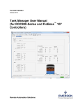
NOA-332
Net Oil Analyzer
User Manual
Manual No. 9A-100079514, Rev. 02
© 2007 Cameron International Corporation (“Cameron”). All information
contained in this publication is confidential and proprietary property of Cameron Any
reproduction or use of these instructions, drawings, or photographs without the
express written permission of an officer of Cameron is forbidden.
All Rights Reserved.
Printed in the United States of America.
Manual No. 9A-100079514, Rev. 02
December 2007
Table of Contents
Section 1—Features of the NOA-332 Net Oil Analyzer.............................................. 1 About this Manual—Introduction ............................................................................ 1 Operational Overview............................................................................................. 1 Specific Features.................................................................................................... 3 Specifications ......................................................................................................... 6 Section 2—Setup Instructions.................................................................................. 11 Introduction .......................................................................................................... 11 Operating System................................................................................................. 11 Scan Data Display................................................................................................ 13 Timing Out............................................................................................................ 14 Start-Up Procedure .............................................................................................. 15 Well Test Procedure............................................................................................. 18 Additional Information........................................................................................... 19 Section 3—The Well Test Status Menu ................................................................... 21 Introduction .......................................................................................................... 21 Accessing the Well Test Status Menu .................................................................. 21 Accessing the Timers Menu ................................................................................. 23 Accessing the Current Totals Menu ..................................................................... 23 Accessing the Continuous Totals Menu ............................................................... 25 Accessing the Prorated Totals Menu.................................................................... 26 Accessing the Previous Test Totals Menu ........................................................... 27 Section 4—The Flow Data Menu ............................................................................. 29 Introduction .......................................................................................................... 29 Accessing the Flow Data Menu ............................................................................ 29 Reading the Gas Orifice Meter Flow Data............................................................ 30 Reading the Gas Turbine Meter Flow Data .......................................................... 32 Reading the Emulsion, Free Water, and Gross Volume Flow Data...................... 33 Section 5—The Site Data Menu............................................................................... 35 Introduction .......................................................................................................... 35 Accessing the Site Data Menu ............................................................................. 35 Reading and Entering Site Data Parameters........................................................ 36 Section 6—The Alarm Data Menu ........................................................................... 43 Introduction .......................................................................................................... 43 Accessing the Analog Input Alarm Data Submenu............................................... 43 Analog Input Alarm Data Parameters................................................................... 43 Analog Input Alarm Status Indicators ................................................................... 45 Accessing the Multivariable Transmitter Input Alarm Data Submenu................... 46 Multivariable Transmitter Input Alarm Status Data Parameters............................ 47 December 2007
Page i
Table of Contents
Multivariable Transmitter Input Alarm Status Indicators ....................................... 47 Accessing the Digital Input Alarm Data Submenu ................................................ 48 Digital Input Alarm Data Parameters .................................................................... 48 Digital Input Alarm Status Indicators .................................................................... 48 Accessing the Rate/Volume Alarm Submenu....................................................... 49 Rate/Volume Alarm Data Parameters .................................................................. 49 Rate/Volume Alarm Status Indicators................................................................... 49 Section 7—The Multivariable Transmitter Menu ...................................................... 51 Introduction .......................................................................................................... 51 Accessing the Multivariable Transmitter menu ..................................................... 52 Multivariable Transmitter Parameters................................................................... 53 Section 8—The Time Data Menu............................................................................. 57 Introduction .......................................................................................................... 57 Accessing the Time Data Menu............................................................................ 57 Setting the System Time ...................................................................................... 57 Setting the System Date....................................................................................... 58 Section 9—The Configuration/Setup Menu.............................................................. 59 Introduction .......................................................................................................... 59 Accessing the Configuration/Setup Menu ............................................................ 59 Section 9a—The System Setup Menu ..................................................................... 61 Introduction .......................................................................................................... 61 Accessing the System Setup Menu...................................................................... 61 Warm Restart ....................................................................................................... 65 Section 9b—The Well Test Setup Menu .................................................................. 67 Introduction .......................................................................................................... 67 Accessing the Well Test Setup Menu................................................................... 67 Section 9c—The Flow Setup Menu - Gas Orifice Meter .......................................... 77 Introduction .......................................................................................................... 77 Accessing the Flow Setup Menu .......................................................................... 77 Accessing the Gas Orifice Setup Menu................................................................ 78 Stacked Differential Pressure (DP) Menu............................................................. 87 Orifice Alarm Setup Menu .................................................................................... 88 Accessing the Orifice Alarm Setup Menu ............................................................. 89 Orifice Alarm Parameters ..................................................................................... 89 Section 9d—The Flow Setup Menu - Gas Turbine Meter ........................................ 95 Introduction .......................................................................................................... 95 Accessing the Flow Setup Menu .......................................................................... 95 Accessing the Gas Turbine Setup Menu .............................................................. 96 Gas Components Menu ..................................................................................... 100 Table of Contents
Page ii
December 2007
Turbine Alarm Setup Menu ................................................................................ 101 Accessing the Turbine Alarm Setup Menu ......................................................... 101 Turbine Alarm Parameters ................................................................................. 102 Calibrate Turbine Menu...................................................................................... 106 Section 9e—The Flow Setup Menu - Liquid Turbine Meter ................................... 109 Introduction ........................................................................................................ 109 Accessing the Flow Setup Menu ........................................................................ 109 Accessing the Liquid Turbine Meter Setup Menu ............................................... 110 Turbine Alarm Setup Menu ................................................................................ 118 Accessing the Turbine Alarm Setup Menu ......................................................... 118 Turbine Alarm Parameters ................................................................................. 119 Calibrate Turbine Menu...................................................................................... 123 Section 9f—The Security Setup Menu ................................................................... 127 Introduction ........................................................................................................ 127 Accessing the Security Setup Menu................................................................... 128 Setting Up the Security Information.................................................................... 131 Setting Up Other Operator Codes and Security Levels ...................................... 132 Section 9g—The Alarm Setup Menu...................................................................... 133 Introduction ........................................................................................................ 133 Accessing the Alarm Setup Menu ...................................................................... 133 Accessing the Analog Input Alarm Setup Submenu ........................................... 133 Analog Input Alarm Parameters ......................................................................... 134 Accessing the Digital Input Alarm Setup Submenu ............................................ 137 Digital Input Alarm Parameters........................................................................... 138 Accessing the Rate and Volume Alarm Setup Submenus.................................. 139 Rate/Volume Alarm Parameters......................................................................... 140 Accessing the Multivariable Transmitter Input Alarm Setup Submenu ............... 143 Multivariable Transmitter Input Alarm Parameters ............................................. 143 Section 9h—The Calibration Menu ........................................................................ 147 Introduction ........................................................................................................ 147 Accessing the Calibration Menu ......................................................................... 148 Analog Input Multipoint Calibration Routine........................................................ 149 Analog Input Zero/Span Scale Routine .............................................................. 152 Analog Input Calibration Checkpoint Routine ..................................................... 154 Review Calibration Routine ................................................................................ 157 Section 9i—The Communications Setup Menu...................................................... 159 Introduction ........................................................................................................ 159 Accessing the Comm Ports Setup Menu............................................................ 159 Communications Parameters ............................................................................. 160 December 2007
Page iii
Table of Contents
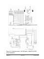
Section 9j—The I/O Config Menu .......................................................................... 165 Introduction ........................................................................................................ 165 Accessing the I/O Configuration Menu ............................................................... 165 The Analog Input Menu ...................................................................................... 165 Accessing the Analog Configuration Menu......................................................... 165 Default Source and Units for Analog Input Channels ......................................... 168 The Digital Input Menu ....................................................................................... 168 Accessing the Digital Input Configuration Menu ................................................. 168 The Digital Output Menu .................................................................................... 169 Accessing the Digital Output Configuration Menu .............................................. 169 Section 9k—The Pulse Output Menu..................................................................... 171 Introduction ........................................................................................................ 171 Accessing the Pulse Output Menu ..................................................................... 171 Appendix A—General Installation Instructions— Weatherproof Unit ......................A-1 Introduction .........................................................................................................A-1 Mounting the Enclosure.......................................................................................A-4 NOA-332 Power Wiring Connections ..................................................................A-6 Analog Circuit Board Transmitter Wiring and Jumper Configuration ...................A-7 Analog Circuit Board Frequency Flowmeter Wiring and Jumper
Configuration .....................................................................................................A-17 Analog Circuit Board Ground Jumper Configuration .........................................A-19 Analog Circuit Board Wiring Diagrams ..............................................................A-19 Digital Circuit Board Setup and Jumper Configuration ......................................A-29 Upgrading NOA-332 System Firmware .............................................................A-30 Appendix B—General Installation Instructions— Rack/Panel Mount Unit...............B-1 Introduction .........................................................................................................B-1 Mounting the Instrument......................................................................................B-4 NOA-332 Power Wiring Connections ..................................................................B-6 Analog Circuit Board Transmitter Wiring and Jumper Configuration ...................B-7 Analog Circuit Board Frequency Flowmeter Wiring and Jumper
Configuration .....................................................................................................B-16 Analog Circuit Board Ground Jumper Configuration .........................................B-17 Digital Circuit Board Setup and Jumper Configuration ......................................B-20 Upgrading NOA-332 System Firmware .............................................................B-21 Appendix C—Menu and Submenu Organizational Charts ..................................... C-1 Appendix D—Spare Parts List ............................................................................... D-1 Appendix E—NuFlo Capacitance Probe & Capacitance Probe Interface Board .....E-1 Introduction .........................................................................................................E-1 Capacitance Probe..............................................................................................E-1 Capacitance Probe Interface Board ....................................................................E-2 Table of Contents
Page iv
December 2007
Selecting Probe Size ...........................................................................................E-5 Configuring the Voltage Output ...........................................................................E-6 Configuring Current Output .................................................................................E-8 Setting a Security Code.....................................................................................E-10 Accessing with a Security Code ........................................................................E-11 Appendix F—Digital Input Output Option – Eight-Input/Eight-Output.....................F-1 General ...............................................................................................................F-1 Digital Inputs........................................................................................................F-1 Digital Outputs.....................................................................................................F-1 Appendix G—Digital Input Output Option - Four-Input/Four Output....................... G-1 General .............................................................................................................. G-1 Digital Inputs....................................................................................................... G-1 Digital Outputs.................................................................................................... G-1 Appendix H—Digital Communications ................................................................... H-1 General .............................................................................................................. H-1 Modem Use with the NOA-332........................................................................... H-6 RS-232 / RS-485 Converters.............................................................................. H-7 December 2007
Page v
Table of Contents
Table of Contents
Page vi
December 2007
Section 1
Features of the NOA-332 Net Oil Analyzer
About this Manual—Introduction
This manual serves as a guide to the installation, configuration, and operation of the NuFlo Model
NOA-332 Net Oil Analyzer. This Section describes the features and specifications of the NOA-332
informing the user of the capabilities of this instrument. Section 2 describes the operating system of
the NOA-332 and gives a step-by-step procedure to install, configure, and operate the NOA-332.
This is accomplished by referring the user to the rest of this manual as it applies to the user’s
application. Several appendices are included at the back of this manual as supplementary
information. The NOA-332 is available in both a weatherproof version and rack/panel mount
version. Refer to Appendix A for installation and maintenance of the weatherproof model. Refer to
Appendix B for installation and maintenance of the rack/panel mount model.
Important—Read Sections 1 and 2 of this manual before attempting to use the NOA-332. The
rest of this manual may be read as needed.
Operational Overview
The NuFlo Net Oil Analyzer, Model NOA-332, is an electronic readout instrument designed for use
with an emulsion separator to determine quantities of produced gas, oil, and water without requiring
the physical separation of the fluids. The NOA-332 may be used with two-phase separators
(gas/emulsion) or three-phase separators (gas/emulsion/free water) and provides real-time analysis of
an emulsion stream determining the amount of water in the emulsion fluid. Signals from turbine
meters, orifice meters, and positive-displacement meters determine the volume of each fluid while a
watercut sensor placed in the emulsion line of the separator determines the percent of water in the
emulsion stream. These signals are read ten times each second and volumes calculated once each
second allowing the NOA-332 to determine well test volumes more accurately than RTUs, PLCs, or
other computing devices.
The NOA-332 provides the user with well test information while providing automatic well test
capabilities, alarm on-off control, and SCADA communications. It may be used with a single well or
where several wells are brought into a common header system to feed into a well test separator. The
NOA-332 allows the operator to program up to sixty-four (64) well names and will associate the well
test data with the name selected, making well test accounting simple. The NOA-332 has three user
selectable operating modes: (1) timed well test, (2) cycled well test, and (3) continuous well test.
Each well name is programmed with a corresponding purge time, test time, and an output action
(optional). The well names and related information are kept in a well test table within the NOA-332
memory.
December 2007
Page 1
Section 1
Operation
In the Timed well test mode, the NOA-332 performs a manual test well function for a single well.
The operator selects the name of the well to be tested and initiates the test by pushing the ‘START’
button. After the purge timer times out, the NOA-332 begins to accumulate well test volumes until
the test timer counts down to zero. During the test, all flow parameters may be viewed via the LCD
on the front panel. At any time, the operator can push the ‘STOP’ button to end the test. While the
test is running, both the raw (actual) volumes and prorated 24-hour volumes (based on the elapsed
time of the test timer) are displayed. When the test timer reaches zero or the ‘STOP’ button is
pushed, the volumes are logged into memory and the instrument ceases gathering data. The logged
volumes are associated by the well name. If the optional DIO board is installed, the operator can
configure the NOA-332 to latch an output signal during the test (purge time plus the test time) or
provide a momentary output signal at the end of the test cycle.
In the Cycled well test mode, the NOA-332 permits automatic well testing. This mode requires the
use of the optional DIO board to switch wells in and out of test. The operator selects the first well to
be tested and presses the ‘START’ button. The NOA-332 will operate as if in the Timed well test
mode counting down the purge timer and then the test timer, with an associated output signal if so
configured. At the end of the test cycle, the NOA-332 will log into memory the well test data, initiate
either a momentary output signal or deactivate the latched output signal (depending upon how
configured), and automatically repeat this process with the next well name listed in the Well Test
Table. The NOA-332 will step down the list of names, testing each well; when the end of the list is
reached, the process will continue starting at the top of the Well Test Table. The operator can push
the ‘STOP’ button at any time to end the testing process and can start anywhere on the list of well
names to start the process. Additionally, the operator can set the test time to zero for a particular well
if this well is to be skipped in the testing sequence. The NOA-332 supports both solenoid-based
systems and step-switched systems.
In the Continuous well test mode, the NOA-332 permits long term well testing (e.g. monitoring of
pipeline fluid from a gathering station). The operator manually starts and stops this test cycle. In this
mode, the test timer is fixed at 24 hours and the well test data is logged into memory at the end of
each 24-hour period. The operator selects the well name and presses the ‘START’ button. After the
purge timer times out, the well test volumes are accumulated on a daily basis. The 24-hour period
defining one day begins when the purge timer reaches zero. During the test, all flow parameters may
be viewed via the LCD on the front panel. At any time, the operator can push the ‘STOP’ button to
end the test. While the test is running, both the raw (actual) volumes and prorated 24-hour volumes
(based on the elapsed time of the test timer) are displayed. Additionally, the operator may view the
accumulated totals which accumulate for the duration of the test period up to a maximum of 366 days.
When the test timer reaches zero, the 24-hour volumes are logged into memory, the test timer is reset
to 24, and the test continues indefinitely until the ‘STOP’ button is pushed. The logged volumes are
associated by the well name.
All flow volume calculations are per the most recent revisions of the American Petroleum Institute
(API) and American Gas Association (AGA). This information is stored in non-volatile memory and
can be downloaded via industry standard SCADA software. Should a power outage occur during a
well test, the well test is concluded with all data safely stored and the display will indicate that the
power outage occurred.
Two auxiliary inputs are available to monitor process parameters. The NOA-332 will maintain a
rolling average of these inputs and maintains these values in memory with the well test data. In
addition to flow parameter data, the NOA-332 stores information related to alarm conditions and
Section 1
Page 2
December 2007
event information related to overall operation of the instrument. The NOA-332 maintains an internal
record of the most recent 256 events and 256 alarms.
Specific Features
Local Readout
The NOA-332 allows the operator to monitor all flowline parameters, well test activity, and alarms on
its 4-Line by 20-character/line Liquid Crystal Display (LCD).
Continuous Volumetric Totals
The NOA-332 continuously updates the volume totals as fluid dumping occurs during the test cycle.
Due to changes in emulsion characteristics between dumps, no watercut signal is used in the
calculations until the emulsion meter registers flow. Emulsion meter pulses are accumulated and
compared against the percent BS&W ten times each second to determine the proportional volumes of
oil and water. This assures the best possible accuracy in well test totals. The gas and free water
meters are monitored continuously. Gross Volume measurement can be accomplished by the use of a
Gross Volume flowmeter. If a meter is not used, Gross Volume is defined as the sum of net oil and
total water.
Communications
The NOA-332 supports off-the-shelf SCADA software using Modbus or Square D RNIM protocols.
Three independent communications ports are available to provide maximum flexibility. All three
communications ports are protected from high-voltage transients.
Data Security
The NOA-332 provides four levels of security for entering setup information and for retrieving well
test data, alarm logs and event logs. Level 1 is limited read-only. Level 2 is full read-only. Level 3
is full read with limited write and Level 4 is full read and full write access. All data stored in memory
is protected by Cameron’s patented internal circuitry which ensures that flow and configuration data
are not altered in the event of a temporary loss of primary power. The battery-backed memory allows
all well test records, alarm logs, and event logs to be available for 5 years.
The communications ports access data in the NOA-332 via register tables. As is customary in
SCADA applications which utilize this method of communication, the user is required to provide
security for data access via the register table. There is no security restriction placed on reading data
or writing data via the communications ports.
December 2007
Page 3
Section 1
Sensor Inputs
The NOA-332 allows for a variety of flowmeter and transmitter inputs to measure flow parameters
specific to net oil computers. The flows measured by the NOA-332 are as follows:
Gas -
Orifice Meter, Turbine Meter, or PD Meter. Inputs available for frequency,
differential pressure, line pressure, and line temperature. In addition, differential
pressure, line pressure, and line temperature may be obtained from a multivariable
transmitter via the COM3 RS-485 port.
Emulsion -
Turbine Meter or PD Meter. Inputs available for frequency, watercut sensor, flowing
pressure, and flowing temperature. The NOA-332 is compatible with the NuFlo
Capacitance Probe or the NuFlo Watercut Monitor.
Free Water -
Turbine Meter or PD Meter. Input available for frequency.
Gross Volume - Turbine Meter or PD Meter. Input available for frequency.
Auxiliary 1 -
Analog signal from a process transmitter. A rolling average of this input is
maintained throughout the well test.
Auxiliary 2 -
Analog signal from a process transmitter. A rolling average of this input is
maintained throughout the well test.
Optional Digital Input / Output (DIO) Board
The Model NOA-332 contains provision to add an optional circuit board that contains discrete switch
inputs and discrete switch (digital) output signals. Two configurations are available consisting of
four switch inputs and four relay outputs or eight switch inputs and eight transistor (FET) outputs.
The switch inputs are configurable and can be used in conjunction with the digital outputs to provide
on/off control features. All switch inputs are protected from high-voltage transients.
The digital outputs operate either as alarm outputs, volumetric pulse outputs, well test outputs, or any
combination thereof:
•
In the alarm output mode, the output may be activated by flowrate, temperature, pressure,
volume, or switch inputs.
•
In the volumetric pulse output mode, the operator defines the pulse width and volume per pulse
for use with remote incremental counters to register gas volume, water volume, oil volume and
gross volume. Incremental flows are calculated once each second, so the volume per pulse rate
must exceed one second.
•
In the well test mode, the operator can configure a specific output for each well name or combine
outputs to produce a binary number representation of the well number (1 to 64) being tested
(especially useful in PLC based switching systems). In latched mode, the output becomes active
when the purge timer starts and deactivates when the test timer counts down to zero or the
‘STOP’ button is pushed. In momentary mode, the output is used to signal the end of the test
cycle when the test timer counts down to zero or the ‘STOP’ button is pushed. The output signal
duration is operator configured from 0.1 to 1.0 seconds. When the operator wishes to skip a well
on the list by setting the test time to zero for that particular well, a momentary output signal will
still occur to automatically switch to the next well to be tested.
Section 1
Page 4
December 2007
CAUTION: The digital outputs are fully configurable allowing all three modes (alarm output,
volumetric pulse output, or well test output) to be intermingled which could cause some
interesting results. All digital outputs are protected from high-voltage transients.
Well Test Table
The NOA-332 maintains an internal table of well names and a corresponding purge time, test time,
and output action (if using the optional DIO board). The table is numbered from 1 thru 64 and the
operator is required to enter well names and associated values in this table. The well names may be
up to 20 characters long. The purge timer is programmable from 0 to 1440 minutes and the well test
timer is programmable from 0 to 72 hours. If the optional DIO board is installed and if the operator
wishes to use the digital outputs as well test outputs, then the operator is required to configure the
DIO option for each well entry. This consists of defining the DO action (none, latched, or
momentary), DO number (1 to 255), and DO width (0.1 to 1.0 second – momentary action only). The
DO number defines which outputs are active when used as well test outputs.
Well Test Data
The NOA-332 internally maintains a log of well test data for each well tested. This log consists of
the following:
•
well name / number
•
actual test volume of gross fluid (Bbls)
•
operator / location
•
24 hour volume of gross fluid (Bbls)
•
time / date of test
•
continuous volume of oil (Bbls)
•
length of well test (hours)
•
continuous volume of total water (Bbls)
•
actual test volume of oil (Bbls)
•
continuous volume of gas (MCF)
•
24 hour volume of oil (Bbls)
•
continuous volume of gross fluid (Bbls)
•
actual test volume of total water (Bbls)
•
percent watercut of gross fluid ( % )
•
24 hour volume of total water (Bbls)
•
•
average flowing value of auxiliary 1
analog input
actual test volume of gas (MCF)
•
•
24 hour volume of gas (MCF)
average flowing value of auxiliary 2
analog input
The most recent well test log can be viewed from the NOA-332 via the LCD display.
Optional Capacitance Probe Interface Board
The venerable NuFlo Capacitance Probe may be used with the NOA-332 via an optional board that
provides power for the Probe and accepts the frequency signal from the Probe. An output signal of 1
to 5 volts DC goes to the NOA-332 Analog Board while an additional 4 to 20 mA signal representing
percent watercut is available for customer use. This board is calibrated independently of the NOA332 system using its own on-board display.
December 2007
Page 5
Section 1
Specifications
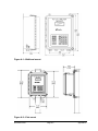
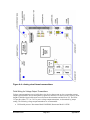
Housing
12 inch by 10 inch by 6-inch fiberglass, NEMA 4 enclosure. Two-inch pole
mount or bulkhead mount. Optional stainless steel weatherproof enclosure or
rack mount enclosure available. See Appendix A for details.
Optional rack/panel mount enclosure for control room environment, fits in 10
½-inch by 19-in. industry standard rack or control panel cutout. See
Appendix B for details.
Environmental
Operating Temperature Range
• external power supply: -40° C to +85° C (-40° F to +185° F)
• LCD & integral power supply: -20° C to +70° C (-4° F to +160° F)
Humidity
• 0 - 90% Non-condensing
System Power
The NOA-332 circuitry, voltage transmitters, and the NuFlo Capacitance
Probe operate on 12 volt DC power. Current output transmitters and the
NuFlo Watercut Monitor operate on 24 volt DC power. Therefore,
depending upon the transmitters used with the NOA-332, both 12 and 24 volt
power may be required.
External Power Supply
Optional power supply with the following features:
• permits operation up to 85° C (185° F)
• accepts either 230 volt AC or 115 volt AC power and provides both 12
and 24 volt DC power to operate the NOA-332
• housed in a NEMA 4 weatherproof enclosure. Suitable for pole mount
or bulkhead mount.
• solar power system available – consult factory
Integral Power Supply
• AC power module and/or a dc power board mount inside the NOA-332
enclosure and permit the NOA-332 to be operated by 100 to 240 volts
AC or 10 to 30 volts DC.
Analog Inputs
3 wire type: 0 to 5 VDC (includes 1 to 5 volts), 0 to 20 mA (includes 4 to 20
mA), 100 ohm RTD selectable for two channels. 0.1% full scale (FS)
accuracy - 0.007% FS per °C drift - 0.5% repeatability.
MVT Input
Compatible with the Rosemount Model 3095FB Multivariable™ Gage
Pressure Transmitter with Modbus™ Protocol via the COM3 RS-485 port.
Display
4-line by 20-character/line alphanumeric liquid crystal display (LCD)
Keypad
24-key membrane switch, tactile response keypad; provides parameter
viewing and setup/calibration
Memory
512 KB static RAM with lithium battery backup, 5-year data retention
Section 1
Page 6
December 2007
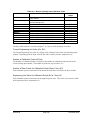
Frequency Inputs
Communication
DIO Board
Four (4) independent inputs each configurable as:
• NuFlo line amplifier (frequency: 1 to 3,000 Hz)
•
low level (frequency: 1 to 3,000 Hz, amplitude: 20 mV to 10 V)
•
positive displacement (PD) meter (dry-contact closure)
Selectable baud rate, each com port independent (1200, 2400, 4800, 9600,
and 19200), Modbus and Square D RNIM protocols, jumper selectable RS485 termination, supports pre and post radio delay, all ports protected from
high voltage transients
•
COM1 - RS-232 DCE
•
COM2 – jumper selectable, RS-232 DTE or RS-485. Modbus slave port
•
COM3 - RS-485. Modbus slave or Modbus master
Optional circuit boards with the following features:
Four (4) Channel Board
• Four relays (dry contact) – 1 Amp @ 30 volts DC – form C contacts
•
Four Optoisolators – 40 mA @ 12 volts DC – form A
•
Four switch inputs – 12 mA @ 12 volts DC max ‘on’ current, 650 us
minimum pulse width
Eight (8) Channel Board
• Eight Transistor (FET) – 1 Amp @ 30 volts DC, not to exceed 4 amps
total ‘on’ current
•
December 2007
Eight switch inputs – 12 mA @ 12 volts DC max ‘on’ current, 650 us
minimum pulse width
Page 7
Section 1
Capacitance
Probe
Optional circuit board that provides power and accepts frequency signal
from the NuFlo Capacitance Probe. Two analog output signals: 1 to 5 volts
DC goes to the NOA-332 Analog Board; 4 to 20 mA signal representing
Percent Watercut available for customer use. Calibration is separate from the
NOA-332.
Calculations
Gas Compressibility
• PAR Research Project NX-19 (3 component & 20 component versions)
• American Gas Association (AGA) Report #8-1985, AGA Report #8 (3
component & 20 component versions)
• User-entered constant
Gas Flow
• American Gas Association (AGA) Report #3 (1985 & 1992 versions)
Liquid Flow Compensation
• Temperature-compensated according to API MPMS Chapter 11.1, Table
6A, 6B, 6C, 24A, 24B, or 24C.
•
Pressure compensated according to API MPMS Chapter 11.2.1 or
Chapter 11.2.2.
Gas Turbine / PD Flow
• American Gas Association (AGA) Report #7
Liquid Turbine / PD Flow
• API MPMS Chapter 5.3 & Chapter 12.2
Section 1
Page 8
December 2007
December 2007
Page 9
Section 1
Notes
Section 1
Page 10
December 2007
Section 2
Setup Instructions
Introduction
The NOA-332 is designed to be easy to install and operate. However, the NOA-332 is a powerful
flow computer with fully configurable hardware and operating system, giving the user dozens of
choices and options to fit the NOA-332 to any test / monitoring application. While the number of
choices can easily be overwhelming, several shortcuts have been added to ease the setup procedure
for the typical well test application or pipeline monitoring application.
Operating System
The NOA-332 is a stand-alone instrument that provides the operator access to all features and data via
the front keypad and LCD display. The NOA-332 groups the operation of the analyzer into nine
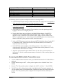
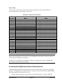
categories. Appendix C illustrates the main menu and submenus for the NOA-332. Table 2.1 lists the
nine menu categories, descriptions of their functions, and the Section of this manual that provides
detailed instructions for accessing functions and data in the submenus.
From the Main menu, you can select a specific category and access submenus to perform a specific
function. Use the and keys while in a menu to move to a menu selection above or below the
current selection. Common functions also have shortcut keys to allow quick access to these functions
without sorting through the menus.
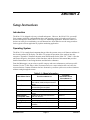
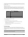
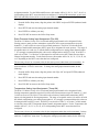
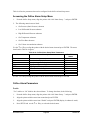
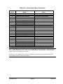
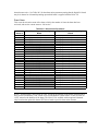
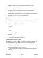
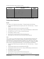
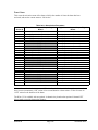
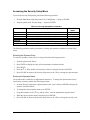
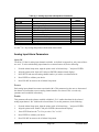
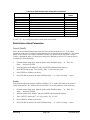
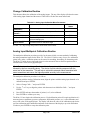
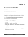
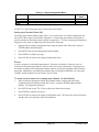
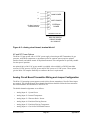
Table 2.1—Menu Information
Main Menu Choice
Test Status
Flow Data
Site Data
Alarm Data
Multivariable
Transmitter Data
Time Data
Config/Setup...
Diagnostics...
Logout...
December 2007
Use this submenu to
View test status information including
timer values, totals, and previous test
values
View the flow parameters for all flow
volumes being accumulated
Read and set site specific parameters
Read the status of all alarms in the
system
Enable use of MVT and monitor the
data from the MVT
Read or set the current time and date
Operating system configuration
Test system operation and locate
problems
Cancels the current security access
Page 11
Find more
information about
this submenu in
Section 3
Section 4
Section 5
Section 6
Section 7
Section 8
Section 9
Section 10
Section 11
Section 2
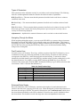
Types of Parameters
Some parameters in the submenus can only be read; others can be read and changed. The following
terms are used throughout this manual to describe the read/write status of parameters:
R/W (Read/Write)—This term means that the parameter described can be read from or written to
(modified) in the menu.
RO (Read Only)—This term means that the parameter described can be read but not altered in the
menu.
WO (Write Only)—This term means that the parameter described can be written to but not read. The
Write-Only provision is used in the Security Setup menu to prevent a person’s security code or
security level from being displayed.
Alphanumeric—Alphabetical or numerical characters can be read and or written in this location.
Navigating Through the Menus
While navigating through the menus, you can press the ESCAPE key to return to the previous menu.
Repeatedly pressing the ESCAPE key will eventually return you to the Main Menu. This feature is
also useful if you are in a menu that requests a change to data that does not require changing. Pressing
the ESCAPE key before pressing the ENTER key allows you to exit the menu without making
changes to the existing data.
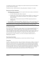
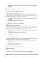
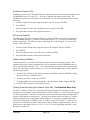
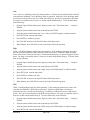
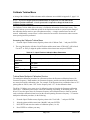
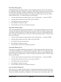
Dual-Function Keys
Several keys have two functions. These keys, with the exception of the Well Test Status key, have a
combination of white-on-red lettering and black-on-white lettering. The black-on-white lettering
corresponds to the SHIFT key, which also has black-on-white lettering. To activate the feature
identified by the black lettering, press the SHIFT key and then release it before pushing the key with
the alternate function. For example, press the SHIFT and then the HOME key to go to the first
selection of the current menu. Press the SHIFT and then the END key to go to the last selection of the
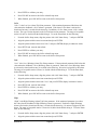
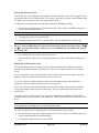
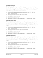
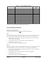
current menu. Table 2.2 lists the dual-function keys.
First Key Function
Config Test
Plate
Start Test
↑
↓
Well Test Status
Table 2.2—Dual-Function Keys
Secondary Key Function
Diagnostics
Communications
Stop Test
Home (beginning selection of menu)
End (end selection of menu)
Scan
Enhanced Mode Display
Due to the limitations of the LCD display, sometimes a description of a particular menu item is
unclear or the data value is too large to be fully seen. When this happens, position the pointer next to
that menu item and press ENTER. This action will display the item in enhanced mode, which shows
the selected item individually on the LCD so that there is room for more specific information about
the selected item. This function is useful with large data values and alphanumeric data items.
Section 2
Page 12
December 2007
The enhanced mode is also useful whenever you need to input data into the NOA-332. Once you put
the system in enhanced mode, you can scroll through parameters and enter data without having to exit
the enhanced mode.
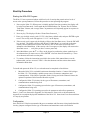
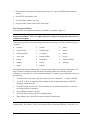
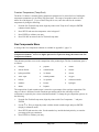
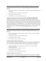
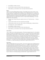
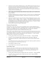
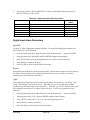
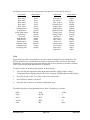
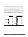
Alphanumeric Data Entry
Alphanumeric data can be entered from the keypad. This feature is used for entering security data,
wellsite data, and well name information. The number keys have a secondary set of labels listed on
each key under the number. These labels represent additional characters, such as letters of the
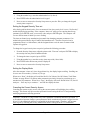
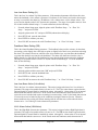
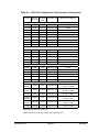
alphabet, that are available for the key. Table 2.3 lists the additional characters available for each key.
Number Key
1
2
3
4
5
6
7
8
9
0
Table 2.3—Available Characters
Characters Available
+ - ! @ # $ % ^ & * ( ) _ = { }[ ] | : ; < > , . ? / →
ABC
DEF
GHI
JKL
MNO
PRS
TUV
WXY
Q Z (space)
To enter alphanumeric data, follow this procedure:
1.
Press the number key.
2.
Press the
3.
Repeat Steps 1 and 2 until the data is completely entered. (Pressing the next number
automatically enters the previous choice.)
or
key until the desired character is displayed.
If you make a mistake, use the backspace key to back up and erase the error.
4.
Press ENTER when finished.
Scan Data Display
Sometimes, certain parameters must be made available to field technicians and other company
personnel who do not have access to a NOA-332 security code. The NOA-332 can be set up so that it
will repeatedly display pre-selected parameters in sequence on the LCD display. This feature is called
Scan Mode.
Note—The Site Identification, Gas Volume, Net Oil Volume, Total Water Volume, and Average
Water Cut parameters are default selected to be displayed in scan mode in the NOA-332. These can
be deselected with the exception of Site Identification.
December 2007
Page 13
Section 2
A maximum of 20 parameters can be displayed in scan mode. Items from any menu can be added to
or removed from the scan sequence.
The default scan time, which determines how long each parameter is displayed, is 2 seconds.
Setting Up the Scan Parameters
1.
Select the parameter to be placed in the scan sequence in the same way that you would select it
for viewing in the menu structure:
a. Press ESCAPE until the Main Menu is displayed.
b. Align the pointer with the appropriate submenu and press ENTER. (For example, choose
the Site Data Menu if you want to set the location [“Loc”] parameter to be displayed
during scan mode.)
c. Align the pointer with the parameter and press ENTER to display the parameter in
enhanced mode.
2.
Press the SHIFT key followed by the WELL TEST STATUS key. An SC icon will appear at the
lower right corner of the LCD display, indicating that this parameter is selected for scanning.
Note—To deselect a parameter for scanning, press the SHIFT key followed by the WELL TEST
STATUS KEY; the SC icon will disappear to indicate that the parameter is no longer selected.
Activating Scan Mode
Once you have set the scan parameters, set the computer to scan by first pressing the ESCAPE key if
in the enhanced mode. Then press the SHIFT key followed by the WELL TEST STATUS key,
which will start the scan mode regardless of where you are located in the menu structure. However, if
you press the SHIFT key followed by the WELL TEST STATUS key while in enhanced mode, you
will be selecting or deselecting a parameter to be scanned instead of activating scan mode.
After the NOA-332 is in the scan mode, you can leave the instrument unattended while it is
displaying these parameters.
Deactivating Scan Mode
Press ESCAPE or one of the eight function keys on the left side of the NOA-332 keypad.
Timing Out
The NOA-332 has a time-out feature. The way this feature works depends on whether or not the scan
mode is active when time-out occurs. When the computer is not in scan mode, the time-out feature
cancels the security level if a key is not pressed within a certain time limit, and begins scrolling the
scan data or the logo message. The information scrolled depends on the display mode setting in the
Security Setup Menu. See Section 9f for more information about the display mode. If the NOA-332
is in scan mode when it times out, the LCD will continue to scan through the scan data. In either
case, a password is required to perform any function after the NOA-332 has timed out.
Section 2
Page 14
December 2007
Start-Up Procedure
Starting the NOA-332 Program
The NOA-332 uses a password scheme with four levels of security that permit various levels of
access to the system parameters. Follow this procedure to start operating the program:
1.
Power-up the NOA-332. When power is initially applied (first-time operation), the display will
be in the Scan Data mode. In this mode the Site Identification, Gas Volume, Net Oil Volume,
Total Water Volume, and Average Water Cut parameters will repeatedly appear in sequence on
the display.
2.
Press any key. The display will show “Please Enter Password: _ ”.
3.
Enter your six-digit security code (333333 is the factory-default code) and press ENTER to gain
access. The security code will appear as “******” on the display.
4.
If the security code is approved, the display will show the Scan Data screen. Press the ESCAPE
key one time. The display will show the “NOA-332 Main Menu” or revert back to the most
recently selected menu item. Press the ESCAPE key one or more times to back out of the
submenus to the Main Menu (if the security code is not approved, the display will return to the
Scan Data screen….. verify that you have a correct password).
5.
In the Main Menu, press the or key on the keypad to position the pointer symbol next to
the submenu that you want to access. Press ENTER. Also note the nine function keys. These
act as shortcuts and can be used anytime.
6.
To continue, follow the instructions provided in the section of this manual that covers the
submenu that you have accessed. Table 2.1 lists the submenus and the sections that contain
information about them.
To install and operate the NOA-332, several tasks must be completed as listed below:
1.
Mount the NOA-332 in a suitable location non-hazardous location. Connect field wiring to
the NOA-332. This includes a suitable power source, flowmeters, transmitters, and
communications. If the NuFlo Capacitance Probe is being used as the Watercut Sensor, the
optional Capacitance Probe Interface Board is required.
2.
Configure the NOA-332 circuitry for the types of flowmeters, transmitters, and
communications method being used.
3.
Configure the NOA-332 operating system for the types of flowmeters, transmitters, and
communications being used.
4.
Configure the NOA-332 operating system for site parameters and well test parameters.
Items 1, 2, and 3 are discussed in Appendix A of this manual. Please refer to the information in
Appendix A to complete the physical installation of the NOA-332. Items 4 and 5 are discussed below
in a step-by-step format.
Configuration
Once the NOA-332 has been mounted with power, transmitter and flowmeter wiring installed and the
circuitry jumpers configured for the type of flowmeters and transmitters used as described in
December 2007
Page 15
Section 2
Appendix A, the instrument should be turned on. The instructions that follow describe use of the
keypad to enter data into the NOA-332.
CAUTION: As with any computational device, the answers are valid only when accurate
information is provided by the user. “Garbage in – garbage out” applies particularly to flow
computers. The mathematics required by API and AGA algorithms is complex and requires
several parameters. When entering required numbers into the NOA-332 operating system,
make every effort to provide accurate data entry.
Follow the instructions listed above under the section Starting the NOA-332 Program. This will
give access to the operating system. While navigating the menu structure, remember that
pressing the ESCAPE key will back the user out of the submenus and ultimately to the Main
Menu (identified by the title ‘NET OIL ANALYZER’ at the top of the display).
Determine security assignments. The default password allows the user to remove the default
password and reassign new passwords and associated security levels. Use the ESCAPE key to
return to the Main Menu. Press the SETUP key. Scroll down to the Security Setup submenu.
Press ENTER and configure the security codes and security time-out. See Section 9f of this
manual for instructions.
Enter the location data (time, date, and site location info).
STEP 1:
Press the TIME key to set the time and date. See Section 8 of this manual for
instructions.
STEP 2:
Starting from the Main Menu, scroll down to the Site Data submenu. Press ENTER
and configure the site data (instrument identification, location, latitude, elevation, base temp &
base pressure used in calculations, and average barometric pressure). See Section 5 of this
manual for instructions.
Enter the NOA system data (system config and well test info).
STEP 1: Use the ESCAPE key to return to the Main Menu. Press the SETUP key. The pointer
will be at the System Setup submenu. Press ENTER and configure the unit identification, system
voltage, test mode, type of gas meter, use of a Gross Volume meter, and the input channels for the
auxiliary inputs. See Section 9a of this manual for instructions.
STEP 2: Press the CONFIG TEST shortcut key. Align the pointer with the well index number
group and press ENTER to configure the test parameters for a particular well. These parameters
are the well name, purge time, test time, and output actions. The NOA-332 allows setup for 1
thru 64 separate wells. See Section 9b of this manual for instructions.
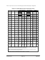
Calibrate the transmitters.
STEP 1:
Using the Transmitter Assignment Worksheet located at the end of Appendix A, note
the analog channel assignments for each of the transmitter inputs used. Refer back to Appendix A
if necessary to determine this. Use the ESCAPE key to return to the Main Menu. Press the
SETUP key. Scroll down to the I/O Config submenu and select Analog Input. Set the transmitter
name and unit label for each analog input channel being used. It is recommended that unused
inputs be renamed to Spare to identify which inputs are not being used. If a Multivariable
Section 2
Page 16
December 2007
transmitter is being used, refer to step 4 below. Refer to Section 9j of this manual for
instructions.
STEP 2:
Use the ESCAPE key to return to the Main Menu. Press the SETUP key. Scroll
down to the Calibration submenu. Press ENTER. Calibrate the analog inputs by selecting the
device from the menu. It is recommended that unused inputs be forced to a calibrated value of
zero. See Section 9h of this manual for instructions.
STEP 3: If the NuFlo Capacitance Probe is being used as the Watercut Sensor, the optional
Capacitance Probe Interface Board is required. Refer to Appendix E. Once the Capacitance
Probe is wired to the Capacitance Probe Interface Board, do the following:
(1) Calibrate the Capacitance Probe to the emulsion fluid it is measuring. See Appendix E
for instructions.
(2) Calibrate the Capacitance Probe to the Capacitance Probe Interface Board. See
Appendix E for instructions.
(3) Calibrate the Capacitance Probe Interface Board to Analog Input #3. The Capacitance
Probe Interface Board has a voltage output feature that makes this easy. See Appendix
E for instructions.
STEP 4: If a Multivariable Transmitter is being used with a gas meter instead of analog
transmitters, the MVT must be configured correctly to operate. Use the ESCAPE key to return to
the Main Menu. Scroll down to the MultiVarTrans submenu. Press ENTER and configure the
multivariable transmitter. Refer to Section 7 of this manual for instructions.
Enter the flowmeter calibration information.
STEP 1:
Use the ESCAPE key to return to the Main Menu. Press the SETUP key. Scroll
down to the Flow Setup submenu. Press ENTER and select the flowmeters that are being used by
scrolling to the meter type and pressing ENTER. Gas, free water, and gross volumes meters are
optional and may not be used in all applications. Each flow can be named and must be
configured before it will calculate volumes. See Sections 9c, 9d, and 9e (as they apply) of this
manual for instructions.
Configure the system alarms (Optional).
STEP 1:
Use the ESCAPE key to return to the Main Menu. Press the SETUP key. Scroll
down to the Alarm Setup submenu. Press ENTER and configure the alarms as desired. See
Section 6 and Section 9g of this manual for instructions.
Configure the communications parameters (Optional).
STEP 1:
Use the ESCAPE key to return to the Main Menu. Press the SETUP key. Scroll
down to the Comm Setup submenu. Press ENTER and select the communications port(s) you
wish to configure. See Section 9i of this manual for instructions. Detailed information regarding
the digital communications is contained in Appendix H.
December 2007
Page 17
Section 2
Configure the input/output parameters (Optional).
STEP 1:
Use the ESCAPE key to return to the Main Menu. Press the SETUP key. Scroll
down to the I/O Config submenu. Press ENTER and select the digital inputs or digital outputs to
configure. See Section 9j of this manual for instructions.
CAUTION: As stated in Section 1, the Model NOA-332 contains provision to add an optional
circuit board that contains either four relay outputs or eight transistor (FET) outputs. These
are referred to as Digital Outputs in this manual and may be configured as alarm outputs
(Section 9g), volumetric pulse outputs (Section 9k), or well test outputs (Section 9b). In the
alarm output mode, the Digital Outputs may be activated by flowrate, temperature, pressure,
volume, or switch inputs. In the volumetric pulse output mode, the operator defines the pulse
width and volume per pulse for use with remote incremental counters to register gas volume,
water volume, oil volume and gross volume. In the well test mode, the operator can configure a
specific output for each well name or combine outputs to produce a binary number
representation of the well number (1 to 64) being tested. The user is cautioned to take note as to
how the digital outputs are configured so as to not create unwanted interactions.
Well Test Procedure
After the Startup Procedure has been completed, the NOA-332 is ready to commission.
STEP 1: If the gas meter being used is an orifice meter, press the PLATE shortcut key and verify that
the plate bore size and meter tube I.D. is correct. These parameters can be changed from this menu
using the SETUP key.
STEP 2: Press the START key and align the pointer with the group of well index numbers you wish
to choose from. Press ENTER and align the pointer with the well name you wish to test. Press
ENTER twice to start the well test. All totals will be initialized to zero and the status of the well test
will be indicated. This same menu is accessible by pressing the WELL TEST STATUS key to view
the status of a test.
NOTE: If the NOA-332 is operating in Timed Test Mode, the system will stop recording volumes
when the timer has counted down to zero. If the NOA-332 is operating in Continuous Test Mode, the
test will run continually until the STOP key is pressed. If the NOA-332 is operating in the Cycle Test
mode, the NOA-332 will complete the current test and then continue testing the remaining wells. See
Section 1 of this manual for a detailed description of how the test modes operate.
STEP 3: The Well Test Status menu lists real-time data of the current well in test or the last well
tested. The information included under this menu consists of the timer values, test totals, and
previous well test totals. This menu is accessed from the NOA-332 Main Menu and is listed as “Test
Status…”. Additionally, pressing the WELL TEST STATUS shortcut key brings the user to this
menu.
NOTE: Pressing the START key while a test is in progress will not abort the test. A message will
appear on the display instructing the user to first stop the current test before trying to initiate a new
test. Whenever a test is initiated, all flow totals are zeroed. When a test is completed, the flow data is
logged into the Previous Test Totals menu as explained the Section 3 of this manual. If a power
Section 2
Page 18
December 2007
outage occurs, the NOA-332 will abort the test, save the existing totals, and indicate ‘Power Failed’
as explained in Section 3 of this manual.
Additional Information
Several Sections of this manual are not listed in the instructions above. The user may benefit from
browsing these Sections as described below:
•
Section 4 - This Section allows the user to view the flow parameters and configuration for each
flow for diagnostic purposes. Some applications operate with intermittent flow, so take note of
the process when viewing the flow parameters.
•
Section 9 - This Section provides an overview for all of the Sections used to enter data into the
NOA-332.
•
Section 9k - This Section allows the user to configure the optional Digital Output parameters.
•
Section 10 - This Section provides full diagnostic access to the NOA-332 operating system and is
very useful for troubleshooting activities.
•
Section 11 - This section allows the user to quickly cancel the current security access.
•
Appendix C - This Section gives the full menu mapping of the keypad system.
•
Appendix D - This Section provides the Spare Parts List for the NOA-332.
•
Appendix F - This Section provides setup information and wiring diagrams for using the eightchannel Digital Output Board. This circuit board is optional.
•
Appendix G - This Section provides setup information and wiring diagrams for using the fourchannel Digital Output Board. This circuit board is optional.
December 2007
Page 19
Section 2
Notes
Section 2
Page 20
December 2007
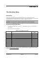
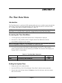
Section 3
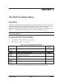
The Well Test Status Menu
Introduction
The Well Test Status menu lists real-time data of the current well in test or the last well tested. The
information included under this menu consists of the timer values, test totals, and previous well test
totals. This menu is accessed from the NOA-332 Main Menu and is listed as “Test Status…”.
Additionally, pressing the WELL TEST STATUS shortcut key brings the user to the menu listed in
Table 3.1. A listing of this menu and its submenus are available in Appendix C, page C-2.
NOTE—A level 1 or higher password authorization is required to view the Well Test Status
Menu and its submenus.
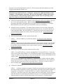
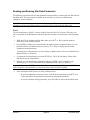
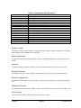
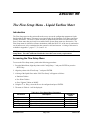
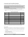
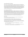
Accessing the Well Test Status Menu
1.
Press the WELL TEST STATUS key on the keypad.
2.
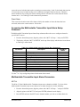
The menu items of table 3.1 are as follows:
Parameters
Well Name &
Status
Mode
Timers…
Current
Totals…
Cont Totals…
Prorated
Totals….
Prv Test
Totals….
Press the
or
December 2007
Table 3.1—Well Test Status Menu Parameters
Description
Current well name and test status
Read/Write
Status
RO
Current well testing mode
Access to the well test timer values
Access to the well test totals. These numbers reset to zero and
the end of each test period
Access to the non-resettable test total for Continuous mode
testing.
Access to the prorated Days Totals
RO
Menu
Menu
Menu
Access to the previous well test totals
Menu
Menu
key to align the pointer with the menu item wanted and press ENTER.
Page 21
Section 3
Well Name & Status
The first line of this menu shows the current well name being tested and the well test status. The
following choices for well test status may appear:
Power Failed -
This message appears when a power failure has occurred.
Purge In-Progress -
This message appears when the purge cycle is in progress.
Test In-Progress -
This message appears when the test cycle is in progress.
Test Complete -
This message appears when the well test has completed.
Test Aborted -
This message appears when the STOP key has been used to complete the
well test cycle.
Alarm -
This message appears when the well test has been halted due to alarm action
25.
Mode
This will be Timed, Continuous, or Cycled depending upon how the instrument was setup by the user
(see Section 2). See Section 1 for an explanation of the operational modes for the NOA-332.
Timers…
The Timers menu contains all of the system timers used for well test purposes. This menu is listed
below under Table 3.2.
Current Totals…
The Current Totals menu contains the accumulated volumes of the well test period. These volumes
are zeroed at the start of each test. In the continuous test mode these volumes are zeroed at the end of
each 24-hour period, based on when the test started. This menu is listed below under Table 3.3.
Cont Totals…
The Cont Totals menu is primarily used with the Continuous Test mode and contains the continuous
accumulated volumes of the well test. The Continuous Totals are not zeroed at the end of each 24hour period as is the case with the Current Totals. The Continuous Totals are zeroed at the start of
each new well test. This menu is listed below under Table 3.4.
Prorated Totals…
The Prorated Totals menu contains the accumulated volumes of the well test prorated to a 24-hour
period. These volumes are zeroed at the start of each test. This menu is listed below under Table 3.5.
Previous Test Totals…
The Previous Test Totals menu contains the accumulated volumes of the previous well test. In the
Timed Test Mode and Cycled Test Mode this menu shows the well name and lists the associated well
test totals. In the Continuous Test Mode, this menu shows the well test totals for the previous 24hour period. This menu is listed below under Table 3.6.
Section 3
Page 22
December 2007
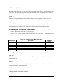
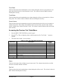
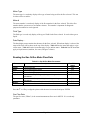
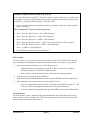
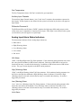
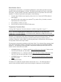
Accessing the Timers Menu
1.
Press the WELL TEST STATUS key on the keypad.
2.
Press the
3.
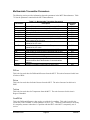
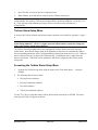
The menu items of table 3.2 are as follows:
or
Table 3.2—Well Test Timers Menu Parameters
Description
Parameters
Current time left until the end of the purge cycle
Current time left until the end of the test cycle
Current elapsed time of the test cycle
PurgLeft
TestLeft
ElpsTime
Press the
key to align the pointer with the menu item “Timers…” and press ENTER.
or
Read/Write
Status
RO
RO
RO
key to align the pointer with the menu item wanted and press ENTER.
Purge Left
This item shows the amount of time left in the purge cycle. The time is shown in whole minutes.
TestLeft
This item shows the amount of time left in the test cycle. The time is shown in hours with two
decimal place accuracy.
ElpsTime
This item shows the amount of elapsed time since the start of the test cycle. The time is shown in
hours with two decimal place accuracy.
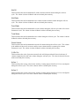
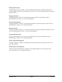
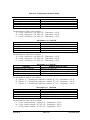
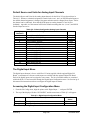
Accessing the Current Totals Menu
1.
Press the WELL TEST STATUS key on the keypad.
2.
Press the
ENTER.
3.
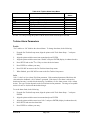
The menu items of table 3.3 are as follows:
December 2007
or
key to align the pointer with the menu item “Current Totals…” and press
Page 23
Section 3
Table 3.3—Well Test Totals Menu Parameters
Description
Parameters
Accumulated gas volume
Accumulated emulsion oil volume
Accumulated emulsion water volume
Accumulated free water volume
Accumulated total water volume
Accumulated gross volume
Percent watercut of the gross liquid volume
Percent watercut of the emulsion volume
Current average value of the Aux #1 input
Current average value of the Aux #2 input
Gas Vol
Net Oil
Net Wtr
Free Wtr
TotalWtr
GrossVol
%Grs Wtr
%Eml Wtr
AvAux 1
AvAux 2
Press the
or
Read/Write
Status
RO
RO
RO
RO
RO
RO
RO
RO
RO
RO
key to align the pointer with the menu item wanted and press ENTER.
Gas Vol
This item shows the total accumulated gas volume during the well test cycle. The volume is shown in
MCF with two decimal place accuracy.
Net Oil
This item shows the total accumulated oil volume from the emulsion stream during the well test
cycle. The volume is shown in Barrels with two decimal place accuracy.
Net Water
This item shows the total accumulated water volume from the emulsion stream during the well test
cycle. The volume is shown in Barrels with two decimal place accuracy.
Free Water
This item shows the total accumulated free water volume during the well test cycle when a free water
flowmeter is used. The volume is shown in Barrels with two decimal place accuracy.
Total Water
This item shows the total accumulated water volume during the well test cycle. The volume is shown
in Barrels with two decimal place accuracy.
Gross Volume
This item shows the total accumulated water and oil volumes during the well test cycle. This volume
is the addition of the net oil, net water, and free water volumes unless a separate gross volume
flowmeter is used. The volume is shown in Barrels with two decimal place accuracy.
% Gross Wtr Cut
This item shows the value of percent watercut determined by the total water volume compared to the
total gross volume during the well test cycle. This represents the watercut of the well being tested.
The value is shown in Percent with two decimal place accuracy.
Section 3
Page 24
December 2007
% Emulsion Wtr Cut
This item shows the value of percent watercut determined by the net water volume compared to the
emulsion volume during the well test cycle. This represents the watercut of the emulsion stream only
and is useful with three-phase separators to give an indication of how well the separator is working.
The value is shown in Percent with two decimal place accuracy.
AvAux 1
This item shows the instantaneous value for the Auxiliary 1 analog input (if the NOA-332 is so
configured) during the well test cycle. The value is shown with two decimal place accuracy.
AvAux 2
This item shows the instantaneous value for the Auxiliary 2 analog input (if the NOA-332 is so
configured) during the well test cycle. The value is shown with two decimal place accuracy.
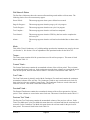
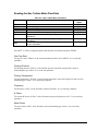
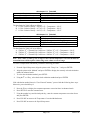
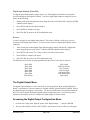
Accessing the Continuous Totals Menu
1. Press the WELL TEST STATUS key on the keypad.
2. Press the
or
key to align the pointer with the menu item “Cont Totals…” and press ENTER.
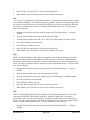
3. The menu items of table 3.4 are as follows:
Parameters
Accumulated gas volume
Accumulated emulsion oil volume
Accumulated emulsion water volume
Accumulated free water volume
Accumulated total water volume
Accumulated gross volume
Gas Vol
Net Oil
Net Wtr
Free Wtr
TotalWtr
GrossVol
Press the
Table 3.4—Cont Test Totals Menu Parameters
Description
or
Read/Write
Status
RO
RO
RO
RO
RO
RO
key to align the pointer with the menu item wanted and press ENTER.
Gas Vol
This item shows the total accumulated gas volume. The volume is shown in MCF rounded to the
nearest whole unit.
Net Oil
This item shows the total accumulated oil volume from the emulsion stream. The volume is shown in
Barrels rounded to the nearest whole unit.
Net Water
This item shows the total accumulated water volume from the emulsion stream. The volume is shown
in Barrels rounded to the nearest whole unit.
December 2007
Page 25
Section 3
Free Water
This item shows the total accumulated free water volume when a free water flowmeter is used. The
volume is shown in Barrels rounded to the nearest whole unit.
Total Water
This item shows the total accumulated water volume. The volume is shown in Barrels rounded to the
nearest whole unit.
Gross Volume
This item shows the total accumulated water and oil volumes. This volume is the addition of the net
oil, net water, and free water volumes unless a separate gross volume flowmeter is used. The volume
is shown in Barrels rounded to the nearest whole unit.
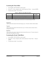
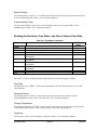
Accessing the Prorated Totals Menu
1.
Press the WELL TEST STATUS key on the keypad.
2.
Press the
ENTER.
3.
The menu items of table 3.5 are as follows:
Parameters
key to align the pointer with the menu item “Prorated Totals…” and press
Table 3.5—24 Hour Totals Menu Parameters
Description
Accumulated prorated gas volume
Accumulated prorated emulsion oil volume
Accumulated prorated emulsion water volume
Accumulated prorated free water volume
Accumulated prorated total water volume
Accumulated prorated gross volume
Gas Vol
Net Oil
Net Wtr
Free Wtr
TotalWtr
GrossVol
Press the
or
or
Read/Write
Status
RO
RO
RO
RO
RO
RO
key to align the pointer with the menu item wanted and press ENTER.
Gas Vol
This item shows the total accumulated gas volume during the well test cycle prorated to a 24 hour
time period. The volume is shown in MCF with one decimal place accuracy.
Net Oil
This item shows the total accumulated oil volume from the emulsion stream during the well test cycle
prorated to a 24 hour time period. The volume is shown in Barrels with one decimal place accuracy.
Net Water
This item shows the total accumulated water volume from the emulsion stream during the well test
cycle prorated to a 24 hour time period. The volume is shown in Barrels with one decimal place
accuracy.
Section 3
Page 26
December 2007
Free Water
This item shows the total accumulated free water volume during the well test cycle prorated to a 24
hour time period when a free water flowmeter is used. The volume is shown in Barrels with one
decimal place accuracy.
Total Water
This item shows the total accumulated water volume during the well test cycle prorated to a 24 hour
time period. The volume is shown in Barrels with one decimal place accuracy.
Gross Volume
This item shows the total accumulated water and oil volumes during the well test cycle prorated to a
24 hour time period. This volume is the addition of the net oil, net water, and free water volumes
unless a separate gross volume flowmeter is used. The volume is shown in Barrels with one decimal
place accuracy.
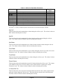
Accessing the Previous Test Totals Menu
1.
Press the WELL TEST STATUS key on the keypad.
2.
Press the
ENTER.
3.
The menu items of table 3.6 are as follows:
Parameters
key to align the pointer with the menu item “Prv Test Totals…” and press
Table 3.6—Prev Test Totals Menu Parameters
Description
Name of well that was tested
Accumulated gas volume
Accumulated emulsion oil volume
Accumulated emulsion water volume
Accumulated free water volume
Accumulated total water volume
Accumulated gross volume
Percent watercut based on the net oil volume and the total
water volume
Current average value of the Aux #1 input
Current average value of the Aux #2 input
Name
Gas Vol
Net Oil
Net Wtr
Free Wtr
TotalWtr
GrossVol
%Wtr Cut
AvAux 1
AvAux 2
Press the
or
or
Read/Write
Status
RO
RO
RO
RO
RO
RO
RO
RO
RO
RO
key to align the pointer with the menu item wanted and press ENTER.
Name
This item is the name of the well that was previously tested. The volumes shown in the rest of this
menu are associated with this well name.
Gas Vol
This item shows the total accumulated gas volume during the well test cycle. The volume is shown in
MCF with two decimal place accuracy.
December 2007
Page 27
Section 3
Net Oil
This item shows the total accumulated oil volume from the emulsion stream during the well test
cycle. The volume is shown in Barrels with two decimal place accuracy.
Net Water
This item shows the total accumulated water volume from the emulsion stream during the well test
cycle. The volume is shown in Barrels with two decimal place accuracy.
Free Water
This item shows the total accumulated free water volume during the well test cycle when a free water
flowmeter is used. The volume is shown in Barrels with two decimal place accuracy.
Total Water
This item shows the total accumulated water volume during the well test cycle. The volume is shown
in Barrels with two decimal place accuracy.
Gross Volume
This item shows the total accumulated water and oil volumes during the well test cycle. This volume
is the addition of the net oil, net water, and free water volumes unless a separate gross volume
flowmeter is used. The volume is shown in Barrels with two decimal place accuracy.
% Wtr Cut
This item shows the value of percent watercut for the well being tested and is based on the net oil
volume compared to the total water volume during the well test cycle. The value is shown in Percent
with two decimal place accuracy.
AvAux 1
This item shows the average value for the Auxiliary 1 analog input (if the NOA-332 is so configured)
during the well test cycle. The value is shown with two decimal place accuracy.
AvAux 2
This item shows the average value for the Auxiliary 2 analog input (if the NOA-332 is so configured)
during the well test cycle. The value is shown with two decimal place accuracy.
Section 3
Page 28
December 2007
Section 4
The Flow Data Menu
Introduction
The Flow Data menu lists real-time data and frequently accessed parameters for each of the four (4)
flows available in the NOA-332. The keypad has a shortcut key that directly accesses this menu.
Pressing the FLOW DATA key brings up the list of flows available. Each flow has a user
configurable name that is listed. Table 4.1 shows the Flow Data menu. A listing of this menu and its
submenus are available in Appendix C, page C-2.
NOTE—A level 1 or higher password authorization is required to view the Flow Data Menu and
its submenus.
Accessing the Flow Data Menu
1.
Press the FLOW DATA key on the keypad.
2.
Align the pointer with the flow name wanted and press ENTER.
3.
The menu items of table 4.1 appear:
Parameters
Meter identification
Meter type
Flow number tracked by the system
Fluid type
Displays flow parameters
FlowID
Mtr Typ
Meter #
Fluid Type
Data
Display….
Press the
Table 4.1—Flow Data Menu Parameters
Description
or
Read/Write
Status
R/O
R/O
R/O
R/O
R/O
key to align the pointer with the menu item wanted and press ENTER.
FlowID
FlowID is a read-only display of the name of the flow selected. This name can be changed by the
user under the Flow Setup menu (Sections 9c, 9d, and 9e).
December 2007
Page 29
Section 4
Meter Type
The meter type is a read-only display of the type of meter being used for the flow selected. This can
be either orifice or turbine.
Meter #
The meter number is a read-only display of the flow number for the flow selected. This is the flow
number that the system uses to accumulate volumes. This number is important for diagnostic
purposes but otherwise can be ignored.
Fluid Type
The fluid type is a read-only display of the type of fluid for the flow selected. It can be either gas or
liquid.
Data Display….
The data display menu contains the submenu for the flow selected. When data display is selected, the
name of the flow will be shown at the top of the display. Table 4.2 lists the items that apply to a gas
orifice meter. Table 4.3 lists the items that apply to a gas turbine meter. Table 4.4 lists the items that
apply to liquid meters (emulsion, free water, and gross volume).
Reading the Gas Orifice Meter Flow Data
Table 4.2—Gas Orifice Meter Parameters
Description
Parameters
Current flow rate
Current differential pressure
Current flowing pressure
Current flowing temperature
Current value of specific gravity being used in gas volume
calculations
Current value of compressibility factor being used in gas volume
calculations
Current value of the orifice plate bore diameter
Current value of the inside diameter of the orifice meter tube.
FlRate
DiffPr
FlPres
FlTemp
SpGrav
Fpv
OrfDia
Tube ID
Press the
or
Read/Write
Status
R/O
R/O
R/O
R/O
R/O
R/O
R/O
R/O
key to align the pointer with the menu item wanted and press ENTER.
Gas Flow Rate
The gas flow rate (“FlRate”) is the current instantaneous flow rate in MCF/D. It is a read-only
parameter.
Section 4
Page 30
December 2007
Differential Pressure
The differential pressure (“DiffPr”) is the current differential pressure read from the differential
pressure transducer and is used to determine gas volume. It is a read-only parameter and is measured
in inches of H2O.
Flowing Pressure
The flowing pressure (“FlPres”) is the flowline pressure expressed in psig which is used in
determining the gas volume. It is a read-only parameter.
Flowing Temperature
The gas temperature (“FlTemp”) is the flowline temperature expressed in degrees F and is used in
determining gas volume. It is a read-only parameter.
Specific Gravity
The specific gravity (“SpGrav”) is a constant value entered in the Flow Setup menu (Section 9c) and
is used in determining gas volume. It is a read-only parameter.
Compressibility Factor
The gas compressibility factor (“Fpv”) is the calculated value for gas compressibility used in
determining gas volume. It is a read-only parameter.
Orifice Plate Bore Diameter
The orifice diameter (“OrfDia”) is the diameter of the orifice plate bore expressed in inches. It is a
read-only parameter.
Orifice Meter Tube Diameter
The orifice tube internal diameter (“TubeID”) is the internal diameter of the orifice meter tube
expressed in inches. It is a read-only parameter.
December 2007
Page 31
Section 4
Reading the Gas Turbine Meter Flow Data
Table 4.3—Gas Turbine Meter Parameters
Description
Parameters
Current flow rate
Current flowing pressure
Current flowing temperature
Current frequency of the flowmeter
Current value of k-factor being used in gas volume calculations
Current value of meter factor being used in gas volume
calculations
Current value of specific gravity being used in gas volume
calculations
Current value of compressibility factor being used in gas
volume calculations
FlRate
FlPres
FlTemp
Freq
K-Fact
MF
SpGrav
Fpv
Press the
or
Read/Write
Status
R/O
R/O
R/O
R/O
R/O
R/O
R/O
R/O
key to align the pointer with the menu item wanted and press ENTER.
Gas Flow Rate
The gas flow rate (“FlRate”) is the current instantaneous flow rate in MCF/D. It is a read-only
parameter.
Flowing Pressure
The flowing pressure (“FlPres”) is the flowline pressure expressed in psig which is used in
determining the gas volume. It is a read-only parameter.
Flowing Temperature
The gas temperature (“FlTemp”) is the flowline temperature expressed in degrees F and is used in
determining gas volume. It is a read-only parameter.
Frequency
The frequency (“Freq”) of the flowmeter expressed in Hertz. It is a read-only parameter.
K-Factor
The current K-Factor (“K-Fact”) of the flowmeter expressed in pulses per ACF. It is a read-only
parameter.
Meter Factor
The meter factor (“MF”) of the flowmeter used in determining gas volume. It is a read-only
parameter.
Section 4
Page 32
December 2007
Specific Gravity
The specific gravity (“SpGrav”) is a constant value entered in the Flow Setup menu (Section 9d) and
is used in determining gas volume. It is a read-only parameter.
Compressibility Factor
The gas compressibility factor (“Fpv”) is the calculated value for gas compressibility used in
determining gas volume. It is a read-only parameter.
Reading the Emulsion, Free Water, and Gross Volume Flow Data
Table 4.4—Liquid Meter Parameters
Description
Parameters
Current flow rate
Current flowing pressure
Current flowing temperature
Current frequency of the flowmeter
Current value of k-factor being used in liquid volume
calculations
Current value of meter factor being used in liquid volume
calculations
Current value of the relative density used in liquid volume
calculations
Current value of API gravity being used in liquid volume
calculations
Current pressure correction factor for liquid volume
Current temperature correction factor for liquid volume
FlRate
FlPres
FlTemp
Freq
K-Fact
MF
RelDen
DegAPI
CPL
CTL
Press the
or
Read/Write
Status
R/O
R/O
R/O
R/O
R/O
R/O
R/O
R/O
R/O
key to align the pointer with the menu item wanted and press ENTER.
Flow Rate
The liquid flow rate (“FlRate”) is the current instantaneous flow rate in Bbls per Day. It is a readonly parameter.
Flowing Pressure
The flowing pressure (“FlPres”) is the flowline pressure expressed in psig which is used in
determining liquid volume. This is often not used. It is a read-only parameter.
Flowing Temperature
The flowing temperature (“FlTemp”) is the flowline temperature expressed in degrees F and is used
in determining liquid volume. This is often not used. It is a read-only parameter.
Frequency
The frequency (“Freq”) of the flowmeter expressed in Hertz. It is a read-only parameter.
December 2007
Page 33
Section 4
K-Factor
The current K-Factor (“K-Fact”) of the flowmeter expressed in pulses per Gallon. It is a read-only
parameter.
Meter Factor
The meter factor (“MF”) of the flowmeter used in determining volume. It is a read-only parameter.
Relative Density
The relative density (“RelDen”) of the liquid is a constant value entered in the Flow Setup menu
(Section 9e) and is used in determining liquid volume. It is a read-only parameter.
API Gravity
The API gravity (“DegAPI”) of the liquid is a constant value entered in the Flow Setup menu
(Section 9e) and is used in determining liquid volume. It is a read-only parameter.
CPL
The pressure correction factor (“CPL”) of the liquid used in determining liquid volume. It is a readonly parameter.
CTL
The temperature correction factor (“CTL”) of the liquid used in determining liquid volume. It is a
read-only parameter.
Section 4
Page 34
December 2007
Section 5
The Site Data Menu
Introduction
The Site Data menu allows you to read and enter parameters into the computer that provide
information about the physical location of the NOA-332. Table 5.1 lists the fourteen (14) menu items
in the Site Data menu. A listing of this menu is available in Appendix C, page C-2.
NOTE—A level 2 or higher password authorization is required to view the items in the Site
Data Menu. A level 4 password is required to change the items in the Site Data Menu.
Accessing the Site Data Menu
1.
Starting from the ‘Main Menu’, press the
press ENTER.
2.
The Site Data menu items will appear:
Parameters
SiteId
Loc
Oper
Lat
Elev
Tbase
Pbase
Pbar
UnitId
SysPwr
BrdTmp
ROMVer
SerNum*
Model
or
key until the pointer is at “Site Data” and
Table 5.1--Site Data Menu Parameters
Description
Site identification, alphanumeric
Site location, alphanumeric
Operator name, alphanumeric
Site latitude
Site elevation
Base temperature used in gas/liquid calculation
Base pressure used in gas/liquid calculation
Average barometric pressure used in gas/liquid calculation
Instrument identification number
System power
System ambient temperature
Firmware version level
Instrument serial number
Indicates model of computer
Read/Write
Status
R/W
R/W
R/O
R/W
R/W
R/W
R/W
R/W
R/O
R/O
R/O
R/O
R/O
R/O
* The default serial number displayed is NOA-9999. The operator can change this number
to the actual serial number of the NOA-332. Once the number is changed from the default
number, it cannot be changed again.
December 2007
Page 35
Section 5
Reading and Entering Site Data Parameters
The following sections describe site data parameters and procedures for entering the site data from the
Site Data menu. These procedures are similar to the ones that you will use to read and enter
parameters in other submenus.
Note—To enter parameters, put the system in enhanced mode. Then you can scroll down to other
parameters and enter data without having to press ESCAPE to return to the Site Data menu.
SiteId
The site identification (“SiteId”) is used to identify where the NOA-332 is located. This entry can
have a maximum of 20 alphanumeric characters and often consists of a station name, tank farm name,
etc.
1.
While the LCD is displaying the Site Data menu, press the
located next to the “SiteId” position.
or
key until the pointer is
2.
Press ENTER to display the site identification in enhanced mode. In enhanced mode, you can
press ESCAPE to exit enhanced mode or press the or key to display other Site Data
information in enhanced mode.
To change the site identification, leave the display in enhanced mode. (For more information on
enhanced mode, see Section 2.)
3.
To change the site identification, press the SETUP key. The LCD will display “Please Enter”
with the current site identification.
4.
Enter the new site identification information and press ENTER. See the example on the
following page. For more information about alphanumeric data entry, see Section 2.
Important—Do not press ENTER until the “SiteId” is completely displayed. If you press ENTER
before completely entering the ID, you must start the procedure from the beginning.
5.
After entering the SiteId, follow one of the guidelines below:
• If you have additional parameters to enter, scroll to the next parameter using the
keys and follow the appropriate instructions for entering the parameter.
and
• If you have finished entering parameters, press ESCAPE to return to the Site Data menu.
Section 5
Page 36
December 2007
Example: Alphanumeric Entry of a Site ID
The new site identification is LAKE #1. This entry is made up of four letters, a space, a symbol, and
then a number. If you have already displayed the parameter in enhanced mode and you have pressed
the SETUP key, perform the following steps to enter this site ID:
1.
Press 5, since the L character is available from this key. Press the
pointer selects the L.
Hint—Pressing the
key three times so that the
key once will also select the L.
2.
Press 2. Press the
key one time. “LA” will be displayed.
3.
Press 5. Press the
key twice. “LAK” will be displayed.
4.
Press 3. Press the
key twice. “LAKE” will be displayed.
5.
Press 0. Press the
key three times. “LAKE ” with a space after the E will be displayed.
6.
Press 1. Press the
key five times. “LAKE #” will be displayed.
7.
Press 1. “LAKE #1” will be displayed.
8.
Press ENTER to complete the entry of the SiteId.
Site Location
The site location (“Loc”) is used to describe the site where the NOA-332 is located. This entry can
have a maximum of 20 alphanumeric characters and often consists of city, state, or county names.
1.
Select the site location parameter in one of the following ways:
• If the Site Data menu is displayed, press the or key to select “Loc” and press
ENTER to display the site location in enhanced mode.
• If the system is already in enhanced mode, scroll to the site location parameter.
2.
To change the site location, press the SETUP key.
3.
Enter the site location with the alphanumeric keys and press ENTER. (See the Example above.)
4.
After entering the site location, follow one of the guidelines below:
• If you have additional parameters to enter, scroll to the next parameter using the
keys and follow the appropriate instructions for entering the parameter.
and
• If you have finished entering parameters, press ESCAPE to return to the Site Data menu.
Local Operator
The local operator (“Oper”) parameter displays the identification of the individual whose security
code was entered. It is a read-only item. If the local operator needs to be changed, modify it in the
Security Setup menu described in Section 9f.
December 2007
Page 37
Section 5
To view the local operator ID, follow these steps:
1.
Select the local operator parameter in one of the following ways:
• Press the or key until the pointer is aligned with the “Oper” position and press
ENTER to view the local operator ID in enhanced mode.
• If the system is already in enhanced mode, scroll to the local operator parameter.
2.
After reading the local operator parameter, follow one of the guidelines below:
• If you have additional parameters to enter, scroll to the next parameter using the
keys and follow the appropriate instructions for entering the parameter.
and
• If you have finished entering and reading parameters, press ESCAPE to return to the Site
Data menu.
Latitude
The site latitude (“Lat”) is the number of degrees north of the equator the instrument is located. Since
the latitude is used in flow calculations, it is important that this value be entered. The range of values
allowable is from 0.0° to 90.0°, and the value can be entered to the nearest one tenth of a degree.
1.
Select the latitude parameter in one of the following ways:
• If the Site Data menu is displayed, press the key until the pointer is aligned with the
“Lat” position and press ENTER to view the latitude in enhanced mode.
• If the system is already in enhanced mode, scroll to the latitude parameter.
2.
To change the latitude value, press SETUP. The display will show “Please Enter” with the
current entered latitude. The minimum and maximum values that can be entered are shown on
the bottom line of the display.
3.
Enter the new value from the keypad using the number keys and the decimal point key.
4.
Once the correct latitude is displayed, press ENTER to complete the entry.
5.
After entering the site location, follow one of the guidelines below:
• If you have additional parameters to enter, scroll to the next parameter using the
keys and follow the appropriate instructions for entering the parameter.
and
• If you have finished entering parameters, press ESCAPE to return to the Site Data menu.
Elevation
The site elevation (“Elev”) is the instrument’s elevation above sea level, measured in feet. Accurate
entry of this parameter is vital since it is used in the flow calculations. The range of acceptable entries
is from 0.0 to 10,000.0 ft.
1.
Select the elevation parameter in one of the following ways:
• If the Site Data menu is displayed, press the or key until the pointer is aligned with
the “Elev” position and press ENTER to view the parameter in enhanced mode.
• If the system is already in enhanced mode, scroll to the elevation parameter.
2.
To change the elevation, press the SETUP key.
3.
Enter the elevation with the 0 to 9 number keys and the decimal point key.
Section 5
Page 38
December 2007
4.
After the correct elevation is displayed, press ENTER to complete the entry.
5.
After entering the elevation, follow one of the guidelines below:
• If you have additional parameters to enter, scroll to the next parameter using the
keys and follow the appropriate instructions for entering the parameter.
and
• If you have finished entering parameters, press ESCAPE to return to the Site Data menu.
Base Temperature
The base temperature (“Tbase”) is the temperature standard to which the gas volume is corrected for
obtaining the standard gas volume. The range of valid entries is from -40.00 to 185.0.
To change or read the base temperature from the Site Data menu, follow these steps:
1.
Select the elevation parameter in one of the following ways:
• If the Site Data menu is displayed, press the or key until the pointer is aligned with
the “Tbase” position and press ENTER to view the parameter in enhanced mode.
• If the system is already in enhanced mode, scroll to the “Base Temperature xx.x Deg F”
parameter.
2.
To change the base temperature, press the SETUP key.
3.
With the number keys and decimal point key, enter the temperature.
4.
After the correct base temperature is displayed, press ENTER to complete the entry.
5.
After entering the base temperature, follow one of the guidelines below:
• If you have additional parameters to enter, scroll to the next parameter using the
keys and follow the appropriate instructions for entering the parameter.
and
• If you have finished entering parameters, press ESCAPE to return to the Site Data menu.
Base Pressure
The base pressure (“Pbase”) is the pressure standard to which the gas volume is corrected to obtain
the standard gas volume. The range of valid entries is from 0.000 to 20.00.
To change or read the base pressure from the Site Data menu, follow these steps:
1.
Select the base pressure parameter in one of the following ways:
• If the Site Data menu is displayed, press the or key until the pointer is aligned with
the “Pbase” position and press ENTER to view the parameter in enhanced mode.
• If the system is already in enhanced mode, scroll to the “Base Pressure xx.xxx PSIA”
parameter.
3.
To change the base pressure, press the SETUP key.
4.
With the 0 to 9 numerical keys and the decimal point key, enter the pressure.
5.
After the correct pressure is displayed, press the ENTER key.
6.
After entering the base pressure, follow one of the guidelines below:
• If you have additional parameters to enter, scroll to the next parameter using the
keys and follow the appropriate instructions for entering the parameter.
December 2007
Page 39
and
Section 5
• If you have finished entering parameters, press ESCAPE to return to the Site Data menu.
Barometric Pressure
The barometric pressure (“Pbar”) is the user-entered value of the average local barometric pressure.
Barometric pressure is an important parameter used in all flow calculations for determining absolute
pressure from gauge pressure. The range of valid entries is from 0.000 to 20.00.
To change or read the barometric pressure from the Site Data menu, follow these steps:
1.
Select the barometric pressure parameter in one of the following ways:
• If the Site Data menu is displayed, press the or key until the pointer is aligned with
the “Pbar” position and press ENTER to view the parameter in enhanced mode.
• If the system is already in enhanced mode, scroll to the “Barometric Pressure xx.xxx
PSIA” parameter.
3.
To change the barometric pressure, press the SETUP key.
4.
With the 0 to 9 numerical keys and the decimal point key, enter the barometric pressure.
5.
After the correct barometric pressure is displayed, press ENTER to complete the entry.
6.
After entering the barometric pressure, follow one of the guidelines below:
• If you have additional parameters to enter, scroll to the next parameter using the
keys and follow the appropriate instructions for entering the parameter.
and
• If you have finished entering parameters, press ESCAPE to return to the Site Data menu.
Unit Identification
The unit identification (“Unit Id”) is an identification number for RS-485 and radio communications
to distinguish this unit from other NOA-332s communicating on the same line or radio frequency.
The unit identification is a read-only parameter. This number is set via dip switch on the digital
circuit assembly (see Appendix A). The range of valid numbers is from 0 to 255.
To read the unit identification from the Site Data menu, follow these steps:
1.
Select the Unit ID parameter in one of the following ways:
• If the Site Data menu is displayed, press the or key until the pointer is aligned with
the “Unit ID” position and press ENTER to view the parameter in enhanced mode.
• If the system is already in enhanced mode, scroll to the “Unit Identification xxx”
parameter.
2.
After reading the unit identification, follow one of the guidelines below:
• If you have additional parameters to enter, scroll to the next parameter using the
keys and follow the appropriate instructions for entering the parameter.
and
• If you have finished entering parameters, press ESCAPE to return to the Site Data menu.
System Power
The system power (“SysPwr”) is the actual voltage read at the NOA-332 power supply input which is
mapped to Analog Input Channel #1. This is a read-only parameter. The measured system power
voltage may be calibrated in the System Setup menu (Section 9a).
Section 5
Page 40
December 2007
To read the system power voltage from the Site Data menu, follow these steps:
1.
Select the system power parameter in one of the following ways:
• If the Site Data menu is displayed, press the or key until the pointer is aligned with
the “SysPwr” position and press ENTER to view the parameter in enhanced mode.
• If the system is already in enhanced mode, scroll to the “System Voltage xx.xx Volts.”
2.
After reading the system voltage, follow one of the guidelines below:
• If you have additional parameters to enter, scroll to the next parameter using the
keys and follow the appropriate instructions for entering the parameter.
and
• If you have finished entering parameters, press ESCAPE to return to the Site Data menu.
Board Temperature
The board temperature (“BrdTmp”) is the temperature of the analog circuit assembly as measured by
a temperature sensor on the analog circuit assembly. This is a read-only parameter.
To read the board temperature from the Site Data menu, follow these steps:
1.
Select the board temperature parameter in one of the following ways:
• If the Site Data menu is displayed, press the key or the key until the pointer is
aligned with the “BrdTmp” position and press ENTER to view the parameter in enhanced
mode.
• If the system is already in enhanced mode, scroll to the “Board Temperature xx.x Deg
F.”
2.
After reading the board temperature, follow one of the guidelines below:
• If you have additional parameters to enter, scroll to the next parameter using the
keys and follow the appropriate instructions for entering the parameter.
and
• If you have finished entering parameters, press ESCAPE to return to the Site Data menu.
Firmware Revision
The firmware revision (“ROMVer”) allows the user to determine the version of firmware in the
NOA-332. The firmware revision number is embedded in the EPROMs, and is not alterable from any
menu in the NOA-332 .
To read the firmware version from the Site Data menu, follow these steps:
1.
Select the firmware revision parameter in one of the following ways:
• If the Site Data menu is displayed, press the or key until the pointer is aligned with
the “ROMVer” position and press ENTER to view the parameter in enhanced mode.
• If the system is already in enhanced mode, scroll to the “Firmware Revision x.xx”
parameter.
2.
After finding the version, follow one of the guidelines below:
• If you have additional parameters to enter, scroll to the next parameter using the
keys and follow the appropriate instructions for entering the parameter.
and
• If you have finished entering parameters, press ESCAPE to return to the Site Data menu.
December 2007
Page 41
Section 5
NOA Serial Number
The NOA-332 serial number (“SerNum”) displays the serial number of the NOA-332. On a NOA332 sent from the factory, this number is preprogrammed into the system’s memory and does not
require user configuration. However, if a digital circuit board is replaced in the unit, the serial number
must be reprogrammed into the NOA-332 .
To read the serial number, select the serial number parameter in one of the following ways:
• If the Site Data menu is displayed, press the or key until the pointer is aligned with
the “SerNum” position and press ENTER to view the parameter in enhanced mode.
• If the system is already in enhanced mode, scroll to the serial number parameter.
If the number is NOA-9999, it can be changed to the serial number of the NOA-332
.
To enter a serial number in place of the default value, follow these steps:
1.
Record the serial number of the NOA-332 (the serial number plate is below the analog circuit
assembly).
2.
While the system is in the enhanced mode, press SETUP.
3.
Enter the alphanumeric serial number. See the example in this section on how to enter
alphanumeric data. Press ENTER.
Caution—Do not press ENTER until you have verified the accuracy of the information typed.
Once ENTER has been pressed, the number is embedded in the system and cannot be changed.
4.
5.
When you are sure that the number is correct, press ENTER.
Press ESCAPE to return to the Site Data menu.
NOA Model Type
The NOA Model Type (“Model”) displays the type of computer as determined by the firmware in the
E-proms. Model types include, but are not limited to: GFC-332, IQV-332, WCU-332, & FC-332. To
read the Model Type, select the model parameter in one of the following ways:
•
If the Site Data menu is displayed, press the or key until the pointer is aligned with the
“Model” position and press ENTER to view the parameter in enhanced mode.
•
If the system is already in enhanced mode, scroll to the model parameter.
Section 5
Page 42
December 2007
Section 6
The Alarm Data Menu
Introduction
The Alarm Data menu consists of four submenus: (1) Analog Input Alarm Data submenu, (2)
Multivariable Transmitter Input Alarm Data submenu, (3) Digital Input Alarm Data submenu, and (4)
Rate/Volume Alarm Data submenu. Each submenu consists of alarm parameters which are
configured in either the Config/Alarm Data menu or the Config/Flow Setup menu. All parameters in
the Alarm Data menu are read-only. A listing of this menu and its submenus are available in
Appendix C, page C-3.
NOTE—A level 2 or higher password authorization is required to view the Alarm Data Menu
and its submenus.
Accessing the Analog Input Alarm Data Submenu
1.
To enter the Alarm Data menu, press ESCAPE until the NOA-332 Main Menu is displayed.
2.
From the Main Menu press the
ENTER.
3.
Press the
or
or
key until the pointer selects “Alarm Data.” Press
key until the pointer is aligned with “Analog Input...”. Press ENTER.
The alarm status will be displayed to the right of each alarm data parameter. To view the enhanced
mode of each alarm data parameter and its individual status, press the or key until the pointer is
aligned with the required selection, and then press ENTER.
Analog Input Alarm Data Parameters
The following section provides information about the parameters in the Analog Input Alarm Data
submenu. The parameters shown are the source names for the analog inputs. Table 6.1 lists the
sixteen available analog inputs as they are configured by default in the NOA-332. However, as this
is configurable by the user, the source names may be different and some of the analog channels may
not be in use. The analog input alarms are not active unless an actual device is connected to the
analog input.
December 2007
Page 43
Section 6
Input
Analog Input #1
Analog Input #2
Analog Input #3
Analog Input #4
Analog Input #5
Analog Input #6
Analog Input #7
Analog Input #8
Analog Input #9
Analog Input #10
Analog Input #11
Analog Input #12
Analog Input #13
Analog Input #14
Analog Input #15
Analog Input #16
Table 6.1—Analog Alarm Input Description
Description
(SysPwr) System Power
(BrdTmp) Board Temperature
(Wtrcut) Percent Watercut
(EmulPr) Emulsion Flowing Pressure
(EmulTm) Emulsion Flowing Temperature
(DiffPr) Gas Orifice Differential Pressure
(GasPr) Gas Meter Flowing Pressure
(GasTmp) Gas Meter Flowing Temperature
Spare Input / (Aux1) Auxiliary Input #1
Spare Input / (Aux2) Auxiliary Input #2
Spare Input / Differential Pressure Hi
Spare Input
Spare Input
Spare Input
Spare Input
Spare Input
System Voltage
The System Voltage alarm (“SysPwr”) monitors the power supply voltage entering the 12Vdc Power
Input terminals on the Analog Circuit Assembly.
Board Temperature
The Board Temperature alarm (“BrdTmp”) monitors the ambient temperature of the Analog circuit
board.
Watercut
The Watercut alarm (“Wtrcut”) monitors the percent watercut indicated by the watercut probe.
Emulsion Pressure
The Emulsion Pressure alarm (“EmulPr”) monitors the line pressure on the emulsion meter run.
Emulsion Temperature
The Emulsion Temperature alarm (“EmulTm”) monitors the line temperature on the emulsion meter
run.
Differential Pressure
The Differential Pressure alarm (“DiffPr”) monitors the differential pressure on the orifice meter run.
Gas Pressure
The Gas Pressure alarm (“GasPr”) monitors the gas line pressure.
Section 6
Page 44
December 2007
Gas Temperature
The Gas Temperature alarm (“GasTmp”) monitors the gas temperature.
Auxiliary Input Channels
The Auxiliary Input Channels alarms (“Aux1” and “Aux2”) monitors the transmitters connected to
these inputs. If these inputs are not defined for the system (see Section 9a), the these will appear as
Spare Inputs.
Differential Pressure Hi
The Differential Pressure Hi alarm (“DiffPr”) monitors the high range differential pressure on the
orifice meter run if a transmitter is connected to this input. If this input is not defined for the system
(see Section 9a), this will appear as a Spare Input.
Analog Input Alarm Status Indicators
The alarm status indicators for the Analog Input Alarms are:
• HiHi Alarm
• High (Warning) Alarm
• Low (Warning) Alarm
• LoLo Alarm
• Not Active
HiHi Alarm
“HiHi” is the High High Alarm Trip Point parameter. If the monitored analog parameter rises above
this value plus the deadband, a HiHi Alarm is indicated. Each time a HiHi alarm is activated or
deactivated an entry is recorded in the alarm log. In addition, a HiHi Alarm causes a HiHi Alarm
Action. The type of action depends on the HiHi Action parameter.
High (Warning) Alarm
“High” is the High (Warning) Alarm Trip Point parameter. If the monitored analog parameter rises
above this value plus the deadband, a High (Warning) Alarm is indicated. Each time a High
(Warning) Alarm is activated or deactivated an entry is recorded in the alarm log. No action is
triggered by this alarm.
Low (Warning) Alarm
“Low” is the Low (Warning) Alarm Trip Point parameter. If the monitored analog parameter falls
below this value minus the deadband, a Low (Warning) Alarm is indicated. Each time a Low
(Warning) Alarm is activated or deactivated an entry is recorded in the alarm log. No action is
triggered by this alarm.
LoLo Alarm
December 2007
Page 45
Section 6
“LoLo” is the Low Low Alarm Trip Point parameter. If the monitored analog parameter falls below
this value minus the deadband, a LoLo Alarm is indicated. Each time a LoLo alarm is activated or
deactivated an entry is recorded in the alarm log. In addition, a LoLo Alarm causes a LoLo Alarm
Action. The type of action depends on the LoLo Alarm Action parameter.
Not Active
"Not Active" status indicates that no alarm condition is present.
Example: Assume that the alarm limits set for the static pressure parameter in the Analog Input
Alarm Setup menu are:
• High High Alarm Trip Point:
1500 PSIG
• High (Warning) Alarm Trip Point:
1000 PSIG
• Low (Warning) Alarm Trip Point:
200 PSIG
• Low Low Alarm Trip Point:
100 PSIG
• Deadband:
20 PSIG
Using the numbers above, the HiHi alarm condition exists when the static pressure is above 1520
PSIG. The high (warning) alarm condition exists when the static pressure is above 1020 PSIG and
below 1480 PSIG. The low (warning) alarm condition exists when the static pressure is above 120
PSIG and below 180 PSIG. The LoLo alarm condition exists when the static pressure is below 80
PSIG. The "Not Active" condition is present when the static pressure is above 200 PSIG and below
1000 PSIG.
Accessing the Multivariable Transmitter Input Alarm Data Submenu
1. To enter the Alarm Data menu, press ESCAPE until the NOA-332 Main Menu is displayed.
2. From the Main Menu press the
ENTER.
or
key until the pointer selects “Alarm Data.” Press
3. Press the
or
key until the pointer is aligned with “MVT AI...”. Press ENTER.
4. Press the
or
key until the pointer is aligned with “MVT 1 to 8 Status...”. Press ENTER.
The Multivariable Transmitter Input Alarm Data Menu contains eight submenus: MVT 1 Status…
through MVT 8 …status. Each submenu represents the alarms status from each of the MVT sources.
Within each submenu the alarm status will be displayed to the right of each alarm data parameter. To
view the enhanced mode of each alarm data parameter and its individual status, press the or key
until the pointer is aligned with the required selection, and then press ENTER.
Section 6
Page 46
December 2007
Multivariable Transmitter Input Alarm Status Data Parameters
The following section provides information about the parameters available in the Multivariable
Transmitter Status Alarm Data submenus. The parameters are the same for all eight of the MVT
Status selections. For information about setting the limits for these alarms, see Section 9g. There are
three parameters listed in each of the MVT Status submenus. These are StPres, StTemp, and DiffPr.
Static Pressure
The Static Pressure alarm (“StPres”) monitors the gas line pressure reported from the MVT via
communications with the NOA-332 COM3 communications port.
Temperature
The Gas Temperature alarm (“StTemp”) monitors the gas temperature reported from the MVT via
communications with the NOA-332 COM3 communications port.
Differential Pressure
The Differential Pressure alarm (“DiffPr”) monitors the differential pressure on the orifice meter run
reported from the MVT via communications with the NOA-332 COM3 communications port.
Multivariable Transmitter Input Alarm Status Indicators
The alarm status indicators for the Multivariable Transmitter Input Alarms are:
• HiHi Alarm
• High (Warning) Alarm
• Low (Warning) Alarm
• LoLo Alarm
• Not Active
HiHi Alarm
“HiHi” is the High High Alarm Trip Point parameter. If the monitored parameter rises above this
value plus the deadband, a HiHi Alarm is indicated. Each time a HiHi alarm is activated or
deactivated an entry is recorded in the alarm log. In addition, a HiHi Alarm causes a HiHi Alarm
Action. The type of action depends on the HiHi Action parameter.
High (Warning) Alarm
“High” is the High (Warning) Alarm Trip Point parameter. If the monitored parameter rises above
this value plus the deadband, a High (Warning) Alarm is indicated. Each time a High (Warning)
Alarm is activated or deactivated an entry is recorded in the alarm log. No action is triggered by this
alarm.
December 2007
Page 47
Section 6
Low (Warning) Alarm
“Low” is the Low (Warning) Alarm Trip Point parameter. If the monitored parameter falls below this
value minus the deadband, a Low (Warning) Alarm is indicated. Each time a Low (Warning) Alarm is
activated or deactivated an entry is recorded in the alarm log. No action is triggered by this alarm.
LoLo Alarm
“LoLo” is the Low Low Alarm Trip Point parameter. If the monitored parameter falls below this
value minus the deadband, a LoLo Alarm is indicated. Each time a LoLo alarm is activated or
deactivated an entry is recorded in the alarm log. In addition, a LoLo Alarm causes a LoLo Alarm
Action. The type of action depends on the LoLo Alarm Action parameter.
Not Active
"Not Active" status indicates that no alarm condition is present.
Accessing the Digital Input Alarm Data Submenu
To enter the Alarm Data menu, press ESCAPE until the NOA-332 Main Menu is displayed.
From the Main Menu press the
Press the
or
or
key until the pointer selects “Alarm Data.” Press ENTER.
key until the pointer is aligned with “Digital Input...”. Press ENTER.
The alarm status will be displayed to the right of each alarm data parameter. To view the enhanced
mode of each alarm data parameter and its individual status, press the or key until the pointer is
aligned with the required selection, and then press ENTER.
Digital Input Alarm Data Parameters
The parameters listed in the Digital Input Alarm Data submenu are all “Spare DI”. These are the
source names assigned by default to the 8 digital inputs. The source names can be changed by
following the procedures in Section 9j and requires the optional Digital I/O circuit board.
Digital Input Alarm Status Indicators
The alarm status indicators for the Digital Inputs Alarms are:
•
No Alarm
•
Not Valid
•
Switch Closed
•
Switch Open
No Alarm
“No Alarm” indicates that there is no alarm condition present.
Section 6
Page 48
December 2007
Not Valid
“Not Valid” indicates that there is no alarm configured for the specified digital input.
Switch Closed
“Switch Closed” indicates that a switch closed alarm condition exists.
Switch Open
“Switch Open” indicates that a switch open alarm condition exists.
Accessing the Rate/Volume Alarm Submenu
To enter the Alarm Data menu, press ESCAPE until the NOA-332 Main Menu is displayed.
From the Main Menu press the
Press the
or
or
key until the pointer selects “Alarm Data.” Press ENTER.
key until the pointer is aligned with “Rate/Volume...”. Press ENTER.
The pointer will point to the meter id (“Mtr Id”) and display the associated alarm status for Rate and
Volume. Press the SETUP key and use the or key to display the flow of choice, then press
ENTER.
Rate/Volume Alarm Data Parameters
The following section provides information about the parameters available in the Rate/Volume Alarm
Data submenu. For information about setting the limits for these alarms, see Section 9g.
Rate
The Flow Rate alarms (“Rate”) monitor the flow rate of each meter.
Volume
The Volume alarms (“Volume”) monitor the volume of each meter.
Rate/Volume Alarm Status Indicators
The alarm status indicators for the Rate/Volume Alarms are:
•
HiHi Alarm
•
High (Warning) Alarm
•
Low (Warning) Alarm
•
LoLo Alarm
•
Not Active
December 2007
Page 49
Section 6
HiHi Alarm
“HiHi” is the High Alarm Trip Point parameter. If the monitored rate/volume parameter rises above
this value plus the deadband, a HiHi Alarm is indicated. Each time a HiHi alarm is activated or
deactivated an entry is recorded in the alarm log. In addition, a HiHi Alarm causes a HiHi Alarm
Action. The type of action depends on the HiHi Action parameter.
High (Warning) Alarm
“High” is the High (Warning) Alarm Trip Point parameter. If the monitored rate/volume parameter
rises above this value plus the deadband, a High (Warning) Alarm is indicated. Each time a High
(Warning) Alarm is activated or deactivated an entry is recorded in the alarm log. No action is tied to
this alarm.
Low (Warning) Alarm
“Low” is the Low (Warning) Alarm Trip Point parameter. If the monitored rate/volume parameter
falls below this value minus the deadband, a Low (Warning) Alarm is indicated. Each time a Low
(Warning) Alarm is activated or deactivated an entry is recorded in the alarm log. No action is tied to
this alarm.
LoLo Alarm
“LoLo” is the Low Low Alarm Trip Point parameter. If the monitored rate/volume parameter falls
below this value minus the deadband, a LoLo Alarm is indicated. Each time a LoLo alarm is activated
or deactivated an entry is recorded in the alarm log. In addition, a LoLo Alarm causes a LoLo Alarm
Action. The type of action depends on the LoLo Alarm Action parameter.
Not Active
"Not Active" status indicates that no alarm condition is present.
Example: Assume that the alarm limits for the gas flow rate are:
•
High High Alarm Trip Point:
•
High (Warning) Alarm Trip Point: 900 MCF/D
•
Low Low Alarm Trip Point:
100 MCF/D
•
Low (Warning) Alarm Trip Point:
300 MCF/D
•
Deadband:
50 MCF/D
1200 MCF/D
Using the numbers above, the HiHi alarm condition exists when the gas flow rate is above 1250
MCF/D. The High (warning) alarm condition exists when the gas flow rate is above 950 MCF/D and
below 1150 MCF/D. The Low (warning) alarm condition exists when the gas flow rate is above 150
MCF/D and below 250 MCF/D. The LoLo alarm condition exists when the gas flow rate is below 50
MCF/D. The "Not Active" status indicator is present when the gas flow rate is above 300 MCF/D
and below 900 MCF/D.
Section 6
Page 50
December 2007
Section 7
The Multivariable Transmitter Menu
Introduction
The NOA-332 can accommodate the use of a Multivariable Transmitter (MVT) to obtain Static
Pressure, Differential Pressure, and Temperature. While these parameters are usually associated with
gas measurement, the NOA-332 allows the assignment of these parameters to gas or emulsion flow.
A listing of this menu and its submenus are available in Appendix C, page C-4.
NOTE—A level 3 or higher password authorization is required to edit the Multivariable
Transmitter override parameters and to enable polling .
Because the MVT is a digital transmitter instead of the usual analog type transmitter, the setup of the
MVT is different. A maximum of eight (8) MVTs may be used with the NOA-332. For each MVT,
the parameters of Differential Pressure, Static Pressure, and Temperature are assigned Input Channel
numbers. The MVT inputs are associated with input channel numbers 25 thru 48 as shown as shown
in Table 7.1 below. These channels numbers are used in the same manner as the analog transmitter
input channel numbers (associated with input channel numbers 1 thru 16) to assign flow parameters to
gas measurement (see Sections 9a, 9c, and 9d), emulsion measurement (see Section 9e), and the
Auxiliary Inputs (see Section 9a).
Table 7.1—MVT Input Channel Assignment
MVT “source” Input
Input Channel Assignment
MVT 1 Differential Pressure
25
MVT 1 Static Pressure
26
MVT 1 Temperature
27
MVT 2 Differential Pressure
28
MVT 2 Static Pressure
29
MVT 2 Temperature
30
MVT 3 Differential Pressure
31
MVT 3 Static Pressure
32
MVT 3 Temperature
33
MVT 4 Differential Pressure
34
MVT 4 Static Pressure
35
MVT 4 Temperature
36
MVT 5 Differential Pressure
37
MVT 5 Static Pressure
38
MVT 5 Temperature
39
MVT 6 Differential Pressure
40
MVT 6 Static Pressure
41
MVT 6 Temperature
42
December 2007
Page 51
Section 7
MVT “source” Input
MVT 7 Differential Pressure
MVT 7 Static Pressure
MVT 7 Temperature
MVT 8 Differential Pressure
MVT 8 Static Pressure
MVT 8 Temperature
Input Channel Assignment
43
44
45
46
47
48
The following steps are required to configure the NOA-332 for using a MVT:
1. Connect the MVT RS-485 wiring to COM3 on the NOA-332 Analog board. See Appendix A
of this manual for an illustration of the wiring connections to COM3.
2. Connect power to the MVT. See Appendix A of this manual for information on power
connections for the MVT.
3. Using the NOA-332 front keypad and LCD user interface, access the operating system by
logging in with a Level 3 or higher password.
4. From the NOA Main menu scroll down to the MultiVarTrans submenu. Each MVT is
configured via a corresponding Data menu as shown in Table 7.2 below. Within each
submenu is a list of parameters used to enable the MVT polling, select the address of the
MVT to be polled, observe the values being read from the MVT, observe the communication
statistics of the MVT polling, and set override values for the MVT.
5. Scroll to MVT ID# parameter and enter the correct MVT Id# (Modbus address) for the MVT
to communicate with. Knowledge of the MVT Id# (Modbus address) set in the MVT is
required in order to do this step.
6. In the MVT Data menu scroll down to the Polling parameter. Select “Enable” to start
communications with the MVT. Observe the communications statistic parameters to verify
communications with the MVT are working.
7. Assign the appropriate MVT input channel number (25 thru 48) to gas measurement (see
Sections 9a, 9c, and 9d), emulsion measurement (see Section 9e), or the Auxiliary Inputs (see
Section 9a).
Accessing the Multivariable Transmitter menu
1.
To enter the Multivariable Transmitter menu, press ESCAPE until the NOA-332 Main Menu is
displayed.
2.
From the Main Menu press the
ENTER.
3.
Press the
4.
The MVT data will be displayed to the right of each Multivariable Transmitter parameter. To
view the enhanced mode of each Multivariable Transmitter parameter and its individual status,
press the or key until the pointer is aligned with the required selection, and then press
ENTER.
Section 7
or
or
key until the pointer selects “MultiVarTrans.” Press
key until the pointer is aligned with “MVT 1 to 8 Data...”. Press ENTER.
Page 52
December 2007
Multivariable Transmitter Parameters
The following section provides information about the parameters in the MVT Data submenus. Table
7.2 lists the parameters contained in the MVT Data submenus.
Parameters
DPLive
PrLive
TmLive
OvrdDPVal
OvrdPrVal
OvrdTmVal
OvrdDP
OvrdPr
OvrdTm
good
Totl
Fail
CRC
MVT Id#
Clear All
Data…
Polling
Table 7.2—Multivariable Transmitter Parameters
Description
Current Differential Pressure reading from the MVT
Current Static Pressure reading from the MVT
Current flowing temperature reading from the MVT
Differential Pressure value used to override the live reading
Static Pressure value used to override the live reading
Temperature value used to override the live reading
Yes or No setting to use the override Differential Pressure
value instead of the live value
Yes or No setting to use the override Static Pressure value
instead of the live value
Yes or No setting to use the override Temperature value
instead of the live value
Percentage of good communications with the MVT
Total number of communications attempted with the MVT
Number of failed communications with the MVT
Number of CRC errors during communications with the MVT
Modbus address of the MVT to poll
Clears the “good” percentage, Total number of
communications and Failed number of communications
statistics
Enables or Disables communications with the MVT
Read/Write
Status
R/O
R/O
R/O
R/W
R/W
R/W
R/W
R/W
R/W
R/O
R/O
R/O
R/O
R/W
R/W
R/W
DPLive
This is the last read value for Differential Pressure from the MVT. This unit of measure for this item
is Inches of H2O.
PrLive
This is the last read value for Static Pressure from the MVT. The unit of measure for this item is
PSIG.
TmLive
This is the last read value for Temperature from the MVT. The unit of measure for this item is
Degrees Fahrenheit.
OvrdDPVal
This is the Differential Pressure value used to override the live reading. This value is used by the
system only if the “OvrdDP” override parameter is set to “yes”. This item is intended to be used only
as a temporary measure when there is a problem with the MVT or the MVT is temporarily out of
service.
December 2007
Page 53
Section 7
OvrdPrVal
Static Pressure value used to override the live reading. This value is used by the system only if the
“OvrdPr” override parameter is set to “yes”. This item is intended to be used only as a temporary
measure when there is a problem with the MVT or the MVT is temporarily out of service
OvrdTmVal
Temperature value used to override the live reading. This value is used by the system only if the
“OvrdTm” override parameter is set to “yes”. This item is intended to be used only as a temporary
measure when there is a problem with the MVT or the MVT is temporarily out of service
OvrdDP
This is a “Yes” or “No” setting that determines whether to use the override Differential Pressure value
instead of the live value.
OvrdPr
This is a “Yes” or “No” setting that determines whether to use the override Static Pressure value
instead of the live value.
OvrdTm
This is a “Yes” or “No’ setting that determines whether to use the override Temperature value instead
of the live value.
good
This is a statistic of the percentage of good communications the NOA-332 has had with the MVT.
Totl
This is the total number of communications the NOA-332 has attempted with the MVT.
Fail
This is the number of failed communications the NOA-332 has had with the MVT.
CRC
This is the number of CRC errors that have occurred during the communications between the NOA332 and the MVT.
MVT Id#
This is the Modbus address of the MVT that the NOA-332 will communicate with. Prior knowledge
of the address set in the MVT is required in order to set this parameter correctly. The address of the
MVT is usually set and stored in the MVT through the use a of separate MVT configuration program.
Section 7
Page 54
December 2007
Clear All Data…
This parameter clears the communication statistic parameters. The items cleared when this operation
is performed are: the “good” percentage, total number of communications, and failed number of
communications.
Polling
This parameter Enables or Disables the communications with the MVT.
December 2007
Page 55
Section 7
Notes
Section 7
Page 56
December 2007
Section 8
The Time Data Menu
Introduction
The Time Data menu is a read/write (R/W) menu that allows the user to read the current time and date
and to enter, or correct, the current time and date. The Time Data menu choices are listed in Table
8.1. A listing of this menu is available in Appendix C, page C-4.
NOTE—A level 1 or higher password authorization is required to view the items in the Time
Data Menu. A level 4 password is required to change the items in the Time Data Menu.
Accessing the Time Data Menu
1.
To enter this menu, press ESCAPE until the NOA-332 Main Menu is displayed.
2.
Press the
3.
Press ENTER to display the time and date.
or
key until the pointer is aligned with the Time Data menu selection.
Hint—A faster way to enter the Time Data menu is to press the TIME key which will access
the menu regardless of where you are located in the menu structure.
4.
To view the time and date individually in enhanced mode, press the or key until the
pointer is aligned with the selection, and then press ENTER. The selection will be displayed as
“System Time” or “System Date.”
Parameters
Table 8.1—Time Data Menu Parameters
Description
Current time of day (HH:MM:SS)
Current date (MM/DD/YYYY)
Time
Date
Read/Write
Status
R/W
R/W
Setting the System Time
1.
Display the time in the enhanced mode.
2.
Press the SETUP key. The LCD will display “Please Enter” and the current system time.
3.
Enter the time in the 24-hour format of hh:mm:ss, where hh is the hours, mm is the minutes
and ss is the seconds.
December 2007
Page 57
Section 8
Note—Each of the entries has to be in double digits; any number less than ten requires a zero in front
of it. The NOA-332 will automatically place the colons (:) during entry.
4.
After entering the time data, press ENTER.
Setting the System Date
1.
Display the date in the enhanced mode.
2.
Press the SETUP key. The LCD will display “Please Enter” and the current system date.
3.
Enter the date in the format of mm/dd/yyyy, where mm is the numerical value of the month, dd
is the current day of the month, and yyyy is the four digits of the current year.
Note—Each of the entries has to be in double digits; any number less than ten requires a zero in front
of it. The NOA-332 will place the forward slash (/) during entry.
4.
After entering the date data, press ENTER.
Example: Setting the Time to 3:06:25 PM
1.
Display the time in enhanced mode.
2.
Press the SETUP key.
3.
Enter 150625.
4.
Press ENTER at exactly 3:06:25 PM. The display will show “System Time 15:06:25” with the
last two digits incrementing once per second.
5.
Press ESCAPE once to display the Time Data menu.
Example: Setting the Date to October 3, 1996
1.
Display the date in enhanced mode.
2.
Press SETUP.
3.
Enter 10031996.
4.
Press ENTER. The LCD will display “System Date 10/03/1996.”
5.
Press ESCAPE once to display the Time Data menu.
Section 8
Page 58
December 2007
Section 9
The Configuration/Setup Menu
Introduction
The Configuration/Setup menu allows you to set up parameters that define the operation of the NOA332. Table 9.1 lists the choices available in the Configuration/Setup menu. These choices provide
access to submenus, which allow the configuration of the operating parameters. Because these setup
submenus have many options within them, this section of the manual is separated into eleven parts as
listed below. A listing of this menu is available in Appendix C, page C-5.
Part 9a - System Setup Menu
Part 9b - Well Test Setup Menu
Part 9c - Flow Setup Menu - Gas Orifice Meter
Part 9d - Flow Setup Menu - Gas Turbine Meter
Part 9e - Flow Setup Menu - Liquid Turbine Meter
Part 9f - Security Setup Menu
Part 9g - Alarm Setup Menu
Part 9h- Calibration Menu
Part 9i - Communications Setup Menu
Part 9j - I/O Configuration Menu
Part 9k- Pulse Output Option Menu
Accessing the Configuration/Setup Menu
To access the Configuration/Setup menu, perform the following procedure:
1.
Starting from the Main Menu, press the SETUP key.
2.
Position the pointer next to the menu item wanted and press ENTER. See the part of this section
(Part 9a through 9k) that contains information about the menu you have chosen.
December 2007
Page 59
Section 9
Parameters
System Setup Menu
Well Test Setup
Menu
Flow Setup Menu
Security Setup Menu
Alarm Setup Menu
Calibration Menu
Comm Setup Menu
I/O Config Menu
Pulse Output Menu
Section 9
Table 9.1—Config/Setup Menu Parameters
Description
Sets unit ID, system voltage, test mode, gas meter type, use of gross
volume meter, analog channel assignments for the watercut probe and
auxiliary inputs, and allows system restart.
Sets the well test parameters for 64 wells. These include the well name,
purge and test times, and optional output actions.
Sets the calculation parameters, analog input assignments, flow related
alarms, and turbine meter calibration for gas and liquid flowmeters.
Sets security information for up to 20 operators
Sets all system alarms – analog inputs, digital inputs, flow rates, and
volumes.
Sets calibration parameters for the analog inputs.
Sets communication parameters for the three communications ports.
Sets the names and units for the analog inputs, digital inputs, and digital
outputs.
Sets the source, pulse width, and volume per count parameters for the
optional pulse outputs.
Page 60
December 2007
Section 9a
The System Setup Menu
Introduction
The NOA-332 requires specific information on how the user wants to configure the instrument for
well testing. For this reason, it is necessary to configure the System Setup menu prior to calibrating
the analog inputs or entering calibration factors for the flowmeters. To permit out-of-the-box
operation, several default values have been programmed into the NOA-332 at the factory and are
usually not changed. However, these parameters may require modification if the computer is
relocated to a new wellsite or if a cold-boot occurs. The System Setup menu contains the parameters
listed in Table 9a.1. A listing of this menu is available in Appendix C, page C-5
NOTE—A level 2 or higher password authorization is required to view the items in the System
Setup Menu. A level 3 or higher password is required to change the items in the System Setup
Menu.
Accessing the System Setup Menu
In the Config/Setup menu, align the pointer with “Systems Setup” and press ENTER.
Table 9a.1—System Setup Menu Parameters
Description
Parameters
Set Unit Id
Voltage
Test mode
Gas Meter
Gross Vol Mtr
Aux-1 AI #
Aux-2 AI #
Warm Restart
Cold Restart
Unit identification number
System voltage
System well test mode
Type of gas flowmeter used
Tells the system if a gross volume flowmeter is being used
Analog input channel assignment for the auxiliary input #1
Analog input channel assignment for the auxiliary input #2
Restarts the computer (reboot)
Complete re-boot of entire system
To access, press the
or
Read/Write
Status
R/W
R/W
R/W
R/W
R/W
R/W
R/W
N/A
N/A
key to align the pointer with the menu selection and then press ENTER
Setting the Unit Id
The unit identification number (“Set Unit Id”) is a unique number that distinguishes a particular
NOA-332 from other instruments connected to a communication system.
The communication protocols (see Section 9i) used in the NOA-332 for acquiring archived data,
runtime data, etc. require a unique identification number to access the NOA-332.
December 2007
Page 61
Section 9a
The NOA-332 unit ID is set with the DIP switch, SW2, on the digital circuit assembly as described in
Appendix A. The DIP switch is an eight-position switch providing unit IDs in the range of 0 to 255.
Each switch position has a value when turned ON that, when added together, form the value of the
unit ID.
The following are the values of each position for the DIP switch:
• Position 1 = 1
• Position 2 = 2
• Position 3 = 4
• Position 4 = 8
• Position 5 = 16
• Position 6 = 32
• Position 7 = 64
• Position 8 = 128
If the switch position is OFF, the value of that position is zero. Thus, if all switches are ON, the value
would be
1+2+4+8+16+32+64+128 = 255.
To set the NOA-332 unit ID, perform the following procedures:
1.
Align the pointer with “Set Unit Id” and press ENTER.
2.
Locate the switch position that has a value as close to the desired unit ID, but not greater.
3.
Set that switch position to ON.
4.
Subtract the value of that switch position from the required unit ID and locate the next switch
position using this number, as described in Step 2.
5.
Repeat Steps 3 and 4 until the unit ID has been set.
Note—The value of the unit ID is displayed in the upper right corner of the LCD as the DIP switch
positions are changed.
6.
7.
Press ENTER when the corrected value of the unit ID is displayed.
Press ESCAPE to return to the System Setup menu.
Section 9a
Page 62
December 2007
Example: Setting Unit Identification
The required unit identification number is 23. The following procedure outlines how to set this unit
ID:
1.
The switch position with the value closest to 23, but not greater, is 5 (value = 16)
Set the Position 5 switch ON.
2.
23 - 16 = 7. The closest position value is 4 (Switch Position 3).
Set the Position 3 switch ON.
3.
7 - 4 = 3. The closest position value is 2 (Switch Position 2).
Set the Position 2 switch ON.
4.
3 - 2 = 1. This corresponds to Switch Position 1.
Set the Position 1 switch ON.
5.
The value of the unit ID for Switch Positions 1, 2, 3, and 5 is 1+2+4+16 = 23. This unit ID is
correct.
Press ENTER to set the unit ID equal to 23.
6.
Press ESCAPE to return to the System Setup menu.
Caution—When changing DIP switch settings, use a light amount of pressure to change the
switch position and avoid adding flex to the circuit assembly. Be careful not to damage the
circuit assembly.
Calibrating the System Voltage Input
The system voltage monitor uses analog input channel 1 and is described in Appendix A. To
calibrate the system voltage input, perform the following procedures:
1. Align the pointer with the “Voltage” parameter.
2. Press ENTER to view the system voltage in enhanced mode.
3. To calibrate the system voltage input, press SETUP. The display will show “Please Enter” with the
current system voltage displayed and the minimum and maximum values that can be entered.
4. Using the number keys and the decimal point key, enter the voltage measured between Terminals 1
and 2 of terminal block TB1 of the analog circuit assembly shown in Appendix A (Terminal 1 =
+12V nominal;
Terminal 2 = Ground). If using the external input, measure the voltage being
applied to the system (e.g. 12 volt solar power feed, 24 volt feed).
5. Once the correct voltage is displayed, press ENTER to complete the calibration.
6. Press ESCAPE to return to the System Setup menu.
December 2007
Page 63
Section 9a
Test Mode
The NOA-332 has three modes of operation, (1) timed mode, (2) continuous mode, and (3) cycled
mode. See Section 1 for a description of the operation of these modes. To summarize, the timed test
mode uses the test timer to end a well test whereas the continuous test mode runs “forever” until the
‘STOP’ key is used to end the well test. The cycle mode is an “automatic” timed mode where the
system stops and starts the test using the well test table. The default mode is “Timed”. To change the
mode of operation:
1. Align the pointer with “Test Mode” and press ENTER (enhanced mode display).
2. Press SETUP and use
and
keys to select the wanted mode.
3. Press ENTER to validate your choice. The display will remain in enhanced mode.
4. Press ESCAPE to return to the System Setup menu.
Gas Meter
The NOA-332 allows only one gas meter, but can utilize either an orifice meter or turbine/PD meter
to calculate gas flow. The default meter is turbine. To change the meter type, do the following:
1. Align the pointer with “Gas Meter” and press ENTER (enhanced mode display).
2. Press SETUP and use
and
keys to select the wanted meter type.
3. Press ENTER to validate your choice. The display will remain in enhanced mode.
4. Press ESCAPE to return to the System Setup menu.
Gross Volume Meter
The NOA-332 allows a Gross Volume flowmeter input for measurement of total liquids using a
turbine or positive displacement flowmeter. If a flowmeter is not used, the Gross Volume totals
indicated by the system will be the arithmetic sum of the liquid totals (net oil, net water, and free
water). To tell the system if a Gross Volume flowmeter is being used, the user must indicate either
“Yes” or “No”. The default is “No”. To change the Gross Volume Meter setting, do the following:
1. Align the pointer with “Gross Vol Mtr” and press ENTER (enhanced mode display).
2. Press SETUP and use
and
keys to select “Yes” or “No”.
3. Press ENTER to validate your choice. The display will remain in enhanced mode.
4. Press ESCAPE to return to the System Setup menu.
Aux1 & Aux2 Analog Input #
The NOA-332 allows two auxiliary inputs as described in Section 1 of this manual. Appendix A
recommends that the Aux 1 input device be connected to analog input number 9 and the Aux 2 input
device be connected to analog input number 10. The default analog input for both Aux 1 and Aux 2
is zero, which tells the system that these inputs are not being used. In addition to the analog input
channel assignment, the MVT channel assignments can be used (see Section 7).
Section 9a
Page 64
December 2007
Warm Restart
A warm restart performs a similar function as a RESET button on a personal computer; it restarts the
NOA-332 operating system. Although a warm restart will cause the NOA-332 to begin operation
from an initial state, it will not lose any archived data, volume totals, or configuration data. However,
if a well test is in progress, the test will be aborted as if a power failure occurred. Warm restart is
useful if problems exist with the communication system in the NOA-332 or if operation problems are
suspected. To perform a warm restart of the NOA-332, perform the following procedures:
1.
Align the pointer with “Warm Restart” and press ENTER. The display will show “Warm Boot
will reset all hardware...*** <Enter> = OK ***”.
2.
To restart the NOA-332, press ENTER. If you do not want to restart the NOA-332 at this time,
press ESCAPE.
After the NOA-332 is restarted, the screen will display the same scrolling message shown when it
was initially put in service.
Cold Restart
A cold restart performs a complete system re-boot erasing everything from memory and reinitializing
all default parameters. In the event that the NOA-332 is operating incorrectly, the system memory
may be corrupted causing erroneous information to be displayed. Although this is very rare, the only
“cure” is to erase all of the system memory. This requires that all calibration data be reentered, so
this action should only be taken as a last resort. When performing a cold restart, refer to Section 2 for
the start-up procedure. To perform a cold restart of the NOA-332, perform the following procedures:
1.
Align the pointer with “Cold Restart” and press ENTER. The display will show “Cold Boot will
RESET all hardware AND Data Logs*** <Enter> = OK ***”.
2.
To restart the NOA-332, press ENTER. If you do not want to restart the NOA-332 at this time,
press ESCAPE.
After the NOA-332 is restarted, the screen will display the same scrolling message shown when it
was initially put in service.
December 2007
Page 65
Section 9a
Notes
Section 9a
Page 66
December 2007
Section 9b
The Well Test Setup Menu
Introduction
The Well Test Setup menu provides the NOA-332 with necessary information on how the user wants
to configure the NOA-332 to test each well. A maximum of 64 wells can be configured, each with
it’s own name, purge and test times, and optional actions. A listing of this menu is available in
Appendix C, page C-5.
NOTE—A level 2 or higher password authorization is required to view the items in the Well
Test Setup Menu. A level 3 or higher password is required to change the items in the Well Test
Setup Menu.
Accessing the Well Test Setup Menu
To access the Well Test Setup menu, press the CONFIG TEST key on the keypad or perform the
following procedure:
1.
From the Main Menu, align the pointer with “Config/Setup...” and press ENTER.
2.
Align the pointer with “Well Test Setup...” and press ENTER.
The NOA-332 will now display a grouping of index numbers ranging from 1 to 64 as shown in Table
9b.1:
Parameters
Wells 01 - 16…
Wells 17 - 32…
Wells 33 - 48…
Wells 49 - 64…
Table 9b.1—Select Setup Well Menu Parameters
Description
Access to data for the first 16 wells
Access to data for the next set of 16 wells
Access to data for the next set of 16 wells
Access to data for the next set of 16 wells
Read/Write
Status
Menu
Menu
Menu
Menu
The NOA-332 can be configured for a maximum of 64 wells which are selected in groups of 16 to
allow users with large numbers of wells quick access without having to scroll down scores of well
names. If the user is unsure of the well index number of a particular well, the well names may be
viewed in groups of 16 as identified in Table 9b.1.
The index numbers ranges from 01 to 64 and the default well names are listed as Well 1, Well 2, Well
3, and so on. Use the or key to align the pointer with the group of index numbers wanted and
press ENTER.
December 2007
Page 67
Section 9b
The NOA-332 will now display a list of well names with an index number. The index number ranges
per the selection made from Table 9b.1. Use the or key to align the pointer with the well
number wanted and press ENTER. The following menu items will appear for each of the sixteen
wells:
Parameters
Name
Purge Time
Test Time
DO Action
DO Number
DO Width
Press the
or
Table 9b.2—Well Test Setup Menu Parameters
Description
Name of the well
Number of minutes for purge timer
Number of hours for well test timer
Type of action performed during the well test (optional)
Number of digital output channel (optional)
Width of momentary digital output (optional)
Read/Write
Status
R/W
R/W
R/W
R/W
R/W
R/W
key to align the pointer with the menu item wanted and press ENTER.
Name
The NOA-332 maintains a user configurable name for each well. The name can consist of any
character and can be up to 20 characters long. To enter a well name, perform the following:
1. Align the pointer with “Name” and press ENTER (enhanced mode display).
2. Press SETUP and enter a well name up to 20 characters and press ENTER.
3. Press ESCAPE to return to the Well Test setup menu.
Purge Time
The NOA-332 has a count-down purge timer that may be set from 0 minutes to 1440 minutes in
whole minute increments. During this time, no volume accumulation occurs. Zero is allowed as an
entry if no purge time is needed. When the purge timer reaches zero, the Well Test Timer begins to
count down. To set the Purge Timer, do the following:
1. Align the pointer with “Purge Time” and press ENTER (enhanced mode display).
2. Press SETUP and enter a number from 0 to 1440.
3. Press ENTER to validate your choice. The display will remain in enhanced mode.
4. Press ESCAPE to return to the Well Test setup menu.
Test Time
The NOA-332 has a count-down test timer that may be set from 0 to 72 hours in whole hour
increments when the NOA-332 is being operated in the Timed test mode or the Cycled test mode.
When in the Continuous test mode, the system will ignore the test time listed in the Well Test Table
and use a 24 hour test time. Flow volumes are accumulated until the Test Timer reaches zero or the
test is aborted with the ‘STOP’ key. Zero is allowed as a valid entry in the Cycled test mode to skip a
well in the well testing sequence (see Section 1).
Section 9b
Page 68
December 2007
To set the test time, do the following:
1. Align the pointer with “Test Time” and press ENTER (enhanced mode display).
2. Press SETUP and enter a number from 0 to 72.
3. Press ENTER to validate your choice. The display will remain in enhanced mode.
4. Press ESCAPE to return to the Well Test setup menu.
DO Action
This parameter is optional and is only operational when a Digital I/O circuit board is installed in the
NOA-332. The choices are None, Latched, or Momentary. The default is None. The Latched action
causes the selected digital output channel to become active when the Test Timer begins to count
down and remain active until the Test Timer reaches zero. The Momentary action causes the selected
digital output channel to become active for a specified number of seconds when the Test Timer
reaches zero. The digital output channel number and specified number of seconds are set in the
following menu items. To set the DO Action, do the following:
1. Align the pointer with “DO Action” and press ENTER (enhanced mode display).
2. Press SETUP and use
and
keys to select the action wanted.
3. Press ENTER to validate your choice. The display will remain in enhanced mode.
4. Press ESCAPE to return to the Well Test setup menu.
DO Number
This parameter is optional and is only operational when a Digital I/O circuit board is installed in the
NOA-332. Depending upon the type of Digital I/O circuit board installed, there may be 4 relay
channels or 8 FET channels available. The DO Number is a value from 1 to 255 and is defined in
Table 9b.3. To enter the DO Number, do the following:
1. Align the pointer with “DO Number” and press ENTER (enhanced mode display).
2. Press SETUP and enter a number from 1 to 255.
3. Press ENTER to validate your choice. The display will remain in enhanced mode.
4. Press ESCAPE to return to the Well Test setup menu.
DO Width
This parameter is optional and is only operational when a Digital I/O circuit board is installed in the
NOA-332. When using a Momentary DO Action, this parameter tells the system how long to keep
the digital output active. The entry can vary from 0.1 to 1.0 seconds. To enter the DO Width, do the
following:
1. Align the pointer with “DO Width” and press ENTER (enhanced mode display).
2. Press SETUP and enter a number from 0.1 to 1.0.
3. Press ENTER to validate your choice. The display will remain in enhanced mode.
4. Press ESCAPE to return to the Well Test setup menu.
December 2007
Page 69
Section 9b
Table 9b.3—DO Number Definition
NOTE: The symbol ☼ indicates an active output. The Digital Output option is available in a four
channel relay version or an eight channel FET (transistor) version. The digital outputs can be
configured to activate one output at a time or represent a binary value (such as the index number of
the well in test) by selecting the appropriate DO Number from the chart below.
(Single Output Action)
DO Number DO1
1
☼
2
4
8
16
32
64
128
(Binary Output Action)
DO Number DO1
1
2
3
4
5
6
7
8
9
10
11
12
13
14
15
16
17
18
19
20
21
22
23
24
25
Section 9b
☼
☼
☼
☼
☼
☼
☼
☼
☼
☼
☼
☼
☼
DO2
DO3
DO4
DO5
DO6
DO7
DO8
☼
☼
☼
☼
☼
☼
☼
DO2
☼
☼
☼
☼
☼
☼
☼
☼
☼
☼
☼
☼
-
DO3
☼
☼
☼
☼
☼
☼
☼
☼
☼
☼
☼
☼
-
DO4
☼
☼
☼
☼
☼
☼
☼
☼
☼
☼
Page 70
DO5
☼
☼
☼
☼
☼
☼
☼
☼
☼
☼
DO6
-
DO7
-
DO8
-
December 2007
DO Number
DO1
26
27
28
29
30
31
32
33
34
35
36
37
38
39
40
41
42
43
44
45
46
47
48
49
50
51
52
53
54
55
56
57
58
59
60
61
62
63
64
65
66
67
December 2007
☼
☼
☼
☼
☼
☼
☼
☼
☼
☼
☼
☼
☼
☼
☼
☼
☼
☼
☼
☼
☼
DO2
☼
☼
☼
☼
☼
☼
☼
☼
☼
☼
☼
☼
☼
☼
☼
☼
☼
☼
☼
☼
☼
☼
DO3
☼
☼
☼
☼
☼
☼
☼
☼
☼
☼
☼
☼
☼
☼
☼
☼
☼
☼
☼
☼
-
DO4
☼
☼
☼
☼
☼
☼
☼
☼
☼
☼
☼
☼
☼
☼
☼
☼
☼
☼
☼
☼
☼
☼
-
Page 71
DO5
☼
☼
☼
☼
☼
☼
☼
☼
☼
☼
☼
☼
☼
☼
☼
☼
☼
☼
☼
☼
☼
☼
-
DO6
☼
☼
☼
☼
☼
☼
☼
☼
☼
☼
☼
☼
☼
☼
☼
☼
☼
☼
☼
☼
☼
☼
☼
☼
☼
☼
☼
☼
☼
☼
☼
☼
-
DO7
☼
☼
☼
☼
DO8
-
Section 9b
DO Number
68
69
70
71
72
73
74
75
76
77
78
79
80
81
82
83
84
85
86
87
88
89
90
91
92
93
94
95
96
97
98
99
100
101
102
103
104
105
106
107
108
109
Section 9b
DO1
☼
☼
☼
☼
☼
☼
☼
☼
☼
☼
☼
☼
☼
☼
☼
☼
☼
☼
☼
☼
☼
DO2
☼
☼
☼
☼
☼
☼
☼
☼
☼
☼
☼
☼
☼
☼
☼
☼
☼
☼
☼
☼
-
DO3
☼
☼
☼
☼
☼
☼
☼
☼
☼
☼
☼
☼
☼
☼
☼
☼
☼
☼
☼
☼
☼
☼
DO4
☼
☼
☼
☼
☼
☼
☼
☼
☼
☼
☼
☼
☼
☼
☼
☼
☼
☼
☼
☼
☼
☼
Page 72
DO5
☼
☼
☼
☼
☼
☼
☼
☼
☼
☼
☼
☼
☼
☼
☼
☼
-
DO6
☼
☼
☼
☼
☼
☼
☼
☼
☼
☼
☼
☼
☼
☼
DO7
☼
☼
☼
☼
☼
☼
☼
☼
☼
☼
☼
☼
☼
☼
☼
☼
☼
☼
☼
☼
☼
☼
☼
☼
☼
☼
☼
☼
☼
☼
☼
☼
☼
☼
☼
☼
☼
☼
☼
☼
☼
☼
DO8
-
December 2007
DO Number
DO1
110
111
112
113
114
115
116
117
118
119
120
121
122
123
124
125
126
127
128
129
130
131
132
133
134
135
136
137
138
139
140
141
142
143
144
145
146
147
148
149
150
151
December 2007
☼
☼
☼
☼
☼
☼
☼
☼
☼
☼
☼
☼
☼
☼
☼
☼
☼
☼
☼
☼
☼
DO2
☼
☼
☼
☼
☼
☼
☼
☼
☼
☼
☼
☼
☼
☼
☼
☼
☼
☼
☼
☼
☼
☼
DO3
☼
☼
☼
☼
☼
☼
☼
☼
☼
☼
☼
☼
☼
☼
☼
☼
☼
☼
☼
☼
☼
☼
DO4
☼
☼
☼
☼
☼
☼
☼
☼
☼
☼
☼
☼
☼
☼
☼
☼
☼
☼
-
Page 73
DO5
☼
☼
☼
☼
☼
☼
☼
☼
☼
☼
☼
☼
☼
☼
☼
☼
☼
☼
☼
☼
☼
☼
☼
☼
DO6
☼
☼
☼
☼
☼
☼
☼
☼
☼
☼
☼
☼
☼
☼
☼
☼
☼
☼
-
DO7
☼
☼
☼
☼
☼
☼
☼
☼
☼
☼
☼
☼
☼
☼
☼
☼
☼
☼
-
DO8
☼
☼
☼
☼
☼
☼
☼
☼
☼
☼
☼
☼
☼
☼
☼
☼
☼
☼
☼
☼
☼
☼
☼
☼
Section 9b
DO Number
152
153
154
155
156
157
158
159
160
161
162
163
164
165
166
167
168
169
170
171
172
173
174
175
176
177
178
179
180
181
182
183
184
185
186
187
188
189
190
191
192
193
Section 9b
DO1
☼
☼
☼
☼
☼
☼
☼
☼
☼
☼
☼
☼
☼
☼
☼
☼
☼
☼
☼
☼
☼
DO2
☼
☼
☼
☼
☼
☼
☼
☼
☼
☼
☼
☼
☼
☼
☼
☼
☼
☼
☼
☼
-
DO3
☼
☼
☼
☼
☼
☼
☼
☼
☼
☼
☼
☼
☼
☼
☼
☼
☼
☼
☼
☼
-
DO4
☼
☼
☼
☼
☼
☼
☼
☼
☼
☼
☼
☼
☼
☼
☼
☼
☼
☼
☼
☼
☼
☼
☼
☼
-
Page 74
DO5
☼
☼
☼
☼
☼
☼
☼
☼
☼
☼
☼
☼
☼
☼
☼
☼
☼
☼
☼
☼
☼
☼
☼
☼
-
DO6
☼
☼
☼
☼
☼
☼
☼
☼
☼
☼
☼
☼
☼
☼
☼
☼
☼
☼
☼
☼
☼
☼
☼
☼
☼
☼
☼
☼
☼
☼
☼
☼
-
DO7
☼
☼
DO8
☼
☼
☼
☼
☼
☼
☼
☼
☼
☼
☼
☼
☼
☼
☼
☼
☼
☼
☼
☼
☼
☼
☼
☼
☼
☼
☼
☼
☼
☼
☼
☼
☼
☼
☼
☼
☼
☼
☼
☼
☼
☼
December 2007
DO Number
DO1
194
195
196
197
198
199
200
201
202
203
204
205
206
207
208
209
210
211
212
213
214
215
216
217
218
219
220
221
222
223
224
225
226
227
228
229
230
231
232
233
234
235
December 2007
☼
☼
☼
☼
☼
☼
☼
☼
☼
☼
☼
☼
☼
☼
☼
☼
☼
☼
☼
☼
☼
DO2
☼
☼
☼
☼
☼
☼
☼
☼
☼
☼
☼
☼
☼
☼
☼
☼
☼
☼
☼
☼
☼
☼
DO3
☼
☼
☼
☼
☼
☼
☼
☼
☼
☼
☼
☼
☼
☼
☼
☼
☼
☼
☼
☼
-
DO4
☼
☼
☼
☼
☼
☼
☼
☼
☼
☼
☼
☼
☼
☼
☼
☼
☼
☼
☼
☼
Page 75
DO5
☼
☼
☼
☼
☼
☼
☼
☼
☼
☼
☼
☼
☼
☼
☼
☼
-
DO6
☼
☼
☼
☼
☼
☼
☼
☼
☼
☼
☼
☼
DO7
☼
☼
☼
☼
☼
☼
☼
☼
☼
☼
☼
☼
☼
☼
☼
☼
☼
☼
☼
☼
☼
☼
☼
☼
☼
☼
☼
☼
☼
☼
☼
☼
☼
☼
☼
☼
☼
☼
☼
☼
☼
☼
DO8
☼
☼
☼
☼
☼
☼
☼
☼
☼
☼
☼
☼
☼
☼
☼
☼
☼
☼
☼
☼
☼
☼
☼
☼
☼
☼
☼
☼
☼
☼
☼
☼
☼
☼
☼
☼
☼
☼
☼
☼
☼
☼
Section 9b
DO Number
236
237
238
239
240
241
242
243
244
245
246
247
248
249
250
251
252
253
254
255
Section 9b
DO1
☼
☼
☼
☼
☼
☼
☼
☼
☼
☼
DO2
☼
☼
☼
☼
☼
☼
☼
☼
☼
☼
DO3
☼
☼
☼
☼
☼
☼
☼
☼
☼
☼
☼
☼
DO4
☼
☼
☼
☼
☼
☼
☼
☼
☼
☼
☼
☼
Page 76
DO5
☼
☼
☼
☼
☼
☼
☼
☼
☼
☼
☼
☼
☼
☼
☼
☼
DO6
☼
☼
☼
☼
☼
☼
☼
☼
☼
☼
☼
☼
☼
☼
☼
☼
☼
☼
☼
☼
DO7
☼
☼
☼
☼
☼
☼
☼
☼
☼
☼
☼
☼
☼
☼
☼
☼
☼
☼
☼
☼
DO8
☼
☼
☼
☼
☼
☼
☼
☼
☼
☼
☼
☼
☼
☼
☼
☼
☼
☼
☼
☼
December 2007
Section 9c
The Flow Setup Menu - Gas Orifice Meter
Introduction
The Flow Setup menu in this section allows the user to access the configuration parameters for the
gas orifice meter. This menu will not be accessible unless the gas meter type has previously been set
to Orifice in the System Setup menu (see Section 9a). The Flow Setup menu is critical for accurate
calculations within the NOA-332, so the user is cautioned to use the utmost care to be certain that the
data entered is valid and accurate. A listing of this menu is available in Appendix C, pages C-9 thru
C-11.
NOTE—A level 2 or higher password authorization is required to view the items in the Flow
Setup Menu. The other submenus listed below have their own security requirements.
Accessing the Flow Setup Menu
To access the Flow Setup menu, perform the following procedures:
1. From the Main Menu, align the pointer with “Config/Setup...” and press ENTER or press the
SETUP key.
2. Align the pointer with “Flow Setup...” and press ENTER.
3. Align the pointer with the Gas Orifice and press ENTER.
4. The menu in Table 9c.1 will be displayed:
Parameters
FlowID
MtrType
Meter #
Fluid Type
Param Setup…
December 2007
Table 9c.1—Flow Setup Menu Parameters
Description
Name of the Gas Orifice flow
Type of meter – Orifice
Number of flow – 1
Type of fluid – Gas
Selected flow parameters submenu
Page 77
Read/Write
Status
R/O
R/O
R/O
R/O
N/A
Section 9c
Accessing the Gas Orifice Setup Menu
NOTE—A level 2 or higher password authorization is required to view the items in the Orifice
Setup submenu. A level 4 password is required to change the items in the Orifice Setup
submenu.
To access the Gas Orifice Setup menu, do the following:
1. From the Flow Setup menu, align the pointer with “Param Setup…” and press ENTER.
2. The display will show “ORIFICE SETUP” and the following parameters in Table 9c.2 will be
listed:
Parameters
FlowID
Ser #
OrfDia
TubeID
SPTap
Type
Fmeth
Rmeth
MinDP
Fpv
Rate
AnnMF
ExpPl
ExpMt
DPlo AI#
DPhi AI#
Flpr AI#
Temp AI#
Fl Press
Temp Value
Hvalue
SG
Gas Comp…
Stacked DP...
Orif Alarm Setup...
Press the
or
Table 9c.2—Gas Orifice Setup Menu
Description
Name of the Gas Orifice flow
Serial number of the orifice meter
Orifice plate bore internal diameter
Orifice meter tube internal diameter
Location of the static pressure tap
Type of differential pressure tap for the orifice
meter
Compressibility calculation method
Flow-rate calculation method
Low differential pressure cutoff value
Override compressibility value for Fmeth
Not Available
Annubar Meter factor
Orifice plate material expansion coefficient
Orifice meter tube expansion coefficient
Analog input channel for low DP transmitter
(stacked DP)
Analog input channel for high DP transmitter
(stacked DP)
Analog input channel for static pressure
Analog input channel for temperature
Override static pressure value
Override flowing temperature value
Heating value of gas
Specific gravity of gas
Gas components submenu
Stacked DP submenu
Orifice alarm submenu
Read/Write
Status
R/W
R/W
R/W
R/W
R/W
R/W
R/W
R/W
R/W
R/W
R/W
R/W
R/W
R/W
R/W
R/W
R/W
R/W
R/W
R/W
R/W
R/W
N/A
N/A
N/A
key to align the pointer with the menu item wanted and press ENTER.
Flow Id (FlowID)
The gas orifice meter identification name is a 20 character alphanumeric parameter. The default
name is Gas Orifice. To change the name, do the following:
Section 9c
Page 78
December 2007
1.
From the Orifice Setup menu, align the pointer with “FlowID” and press ENTER (enhanced
mode display).
2.
Press SETUP and use the number keys (and the
orifice meter identification name.
3.
Press ENTER to validate your choice.
4.
Press ESCAPE to return to the Orifice Setup menu.
key and the
key if needed) to enter the
Serial Number (Ser #)
The orifice serial number is a 20 character alphanumeric serial number provided to trace the operation
of the orifice meter run throughout the lifetime of the meter. The default serial number is Gas Orifice.
Together with the orifice identification name, the orifice meter run can be easily identified. To enter
the orifice serial number, do the following:
1.
From the Orifice Setup menu, align the pointer with “Ser #” and press ENTER (enhanced mode
display).
2.
Press SETUP and use the number keys (and the
orifice serial number.
3.
Press ENTER to validate your entry.
4.
Press ESCAPE to return to the Orifice Setup menu.
key and the
key if needed) to enter the
Orifice Diameter (OrfDia)
The orifice diameter is the internal diameter of the bore in the orifice plate measured in inches. The
range of acceptable entries is from 0 to 10.000 inches. To enter the diameter, do the following:
1.
From the Orifice Setup menu, align the pointer with “OrfDia” and press ENTER (enhanced
mode display).
2.
Press SETUP and use the number keys to enter the diameter.
3.
Press ENTER to validate your entry.
4.
Press ESCAPE to return to the Orifice Setup menu.
Orifice Meter Tube Id (Pipe)
The orifice meter tube Id is the internal diameter of the orifice meter tube measured in inches. The
range of acceptable entries is from 0 to 20.000 inches. To enter the diameter, do the following:
1.
From the Orifice Setup menu, align the pointer with “TubeID” and press ENTER (enhanced
mode display).
2.
Press SETUP and use the number keys to enter the diameter.
3.
Press ENTER to validate your entry.
4.
Press ESCAPE to return to the Orifice Setup menu.
Note—If the beta ratio (orifice bore size ÷ meter tube internal diameter) is less than 0.15 or greater
than 0.70, the system will display the message "Beta ratio out of range. Press any key." The system
will prompt you to modify the other parameter in the beta equation (i.e., either meter tube internal
December 2007
Page 79
Section 9c
diameter if entering orifice bore size or orifice bore size if entering meter tube internal diameter).
Press any key and make the requested modification.
Static Pressure Tap Location (SPTap)
The static-pressure tap location (Upstream or Downstream) identifies the location of
the static pressure sensor in relation to the orifice plate. The NOA-332 allows use of
either an upstream pressure tap or a downstream pressure tap. The default is
Downstream. To enter the pressure tap information, do the following:
1.
From the Orifice Setup menu, align the pointer with “SPTap” and press ENTER (enhanced
mode display).
2.
Press SETUP and use the
3.
Press ENTER to validate your entry.
4.
Press ESCAPE to return to the Orifice Setup menu.
or
key to select “Upstream” or “Downstream”.
Differential Pressure Tap Type (Type)
The differential pressure tap type parameter (flange, pipe, or corner) defines the location of the
differential pressure connections at the orifice meter. The default is Flange. To enter the type of tap
that the differential pressure is connected to, do the following:
1.
From the Orifice Setup menu, align the pointer with “Type” and press ENTER (enhanced mode
display).
2.
Press SETUP and use the
corner).
3.
Press ENTER to validate your entry.
4.
Press ESCAPE to return to the Orifice Setup menu.
or
key to select the appropriate tap location (flange, pipe, or
Compressibility Calculation Method (FMeth)
The compressibility calculation method lists the following methods of calculating the compressibility
factor:
•
AGA8 (1985)
•
AGA8 (analysis of 20 constituent gases)
•
NX19 (analysis of specific gravity, carbon dioxide, and nitrogen)
•
NX19 (analysis of 20 constituent gases)
•
User-entered constant
•
AGA8 (analysis of HV, SG, CO2)
•
AGA8 (analysis of specific gravity, carbon dioxide, and nitrogen)
The default method is NX-19 (SG, CO2, N). To select the compressibility calculation method, do the
following:
1.
From the Orifice Setup menu, align the pointer with “FMeth” and press ENTER (enhanced
mode display).
Section 9c
Page 80
December 2007
2.
Press SETUP and use the
or
key to select the appropriate calculation method.
3.
Press ENTER to validate your entry.
4.
Press ESCAPE to return to the Orifice Setup menu.
NOTE: If the “User-Entered Constant” is selected as the calculation method, the user must enter the
constant value under the “Fpv” menu item described below.
Rate Calculation Method (RMeth)
The flow rate calculation method lists the following methods of calculating totals:
• Lock Current Rate (Not Valid – for future use)
• AGA3 (1985 American Gas Association standard for orifice meters)
• AGA7 (AGA standard for turbine flowmeters)
• ISO-5167 (Not Valid – for future use)
• Annubar meter
• AGA3 (equation) The 1992 version of AGA Report #3 requires pressure measured at the Upstream
Tap. The downstream tap will produce slightly different results than the upstream tap, but can be
used.
• AGA3 (factors)
The default is AGA-3, 1985 method. The user should not select “Lock Curr Rate” as this will cause
inaccurate well test totals to occur. To select the gas flow rate calculation method, do the following:
1.
From the Orifice Setup menu, align the pointer with “RMeth” and press ENTER (enhanced
mode display).
5.
Press SETUP and use the
2.
Press ENTER to validate your entry.
3.
Press ESCAPE to return to the Orifice Setup menu.
or
key to select the appropriate calculation method.
Minimum Differential Pressure (MinDP)
The minimum differential pressure parameter sets a DP threshold that allows the computer to
calculate totals and flow rates only after the differential pressure reaches a certain amount (the default
value is 0.5 Inches of Water). If you want the computer to calculate totals and flow rates regardless
of differential pressure, enter a value of zero. The range of acceptable entries is from 0 to 100.0
inches. If the differential pressure is less than the minimum, the gas flow rate is assumed to be zero.
December 2007
Page 81
Section 9c
To set the minimum differential pressure value, do the following:
1.
From the Orifice Setup menu, align the pointer with “MinDP” and press ENTER (enhanced
mode display).
2.
Press SETUP and enter the minimum differential pressure value in Inches of Water.
3.
Press ENTER to validate your entry.
4.
Press ESCAPE to return to the Orifice Setup menu.
Constant Supercompressibility Factor (Fpv)
The NOA-332 allows a constant supercompressibility parameter to be entered in lieu of calculating
this parameter. The range of acceptable entries is from 0.800 to 2.000 . If you selected “UserEntered Constant” as the compressibility calculation method (FMeth) earlier, enter the value for the
constant by doing the following:
1.
From the Orifice Setup menu, align the pointer with “Fpv” and press ENTER (enhanced mode
display).
2.
Press SETUP and enter the supercompressibility value.
3.
Press ENTER to validate your entry.
4.
Press ESCAPE to return to the Orifice Setup menu.
Constant Flow Rate (Rate)
This parameter is not valid for the NOA-332.
Annubar Meter Factor (AnnMF)
The Annubar meter factor, together with a temperature correction factor and a relative density
correction factor, provides annubar meter measurement capability in the NOA-332. The annubar
meter factor provides the equivalent of the basic orifice factor for annubar meters. The range of
acceptable entries is from 0.5 to 2.0 with a default value of 1.0. To enter the Annubar meter factor,
do the following:
1.
From the Orifice Setup menu, align the pointer with “MF” and press ENTER (enhanced mode
display).
2.
Press SETUP and enter the meter factor.
3.
Press ENTER to validate your entry.
4.
Press ESCAPE to return to the Orifice Setup menu.
Orifice Plate Expansion Coefficient (ExpPl)
The orifice plate expansion coefficient is a number representing the change in the orifice plate
dimensions with respect to changes in temperature. Expansion coefficients for commonly used
orifice plates are listed in Table 9c.3 . The default value is set for stainless steel. To change the
orifice expansion coefficient, do the following:
1. From the Orifice Setup menu, align the pointer with “ExpPl” and press ENTER (enhanced mode
display).
Section 9c
Page 82
December 2007
2.
Press SETUP and enter the expansion coefficient value.
3.
Press ENTER to validate your entry.
4.
Press ESCAPE to return to the Orifice Setup menu.
Orifice Meter Tube Expansion Coefficient (ExpMt)
The orifice meter tube expansion coefficient is a number representing the change in meter tube
dimensions with respect to changes in temperature. Expansion coefficients for commonly used pipe
materials are listed in Table 9c.3 . The default value is for carbon steel. To set the orifice meter tube
expansion coefficient, do the following:
1.
From the Orifice Setup menu, align the pointer with “ExpMt” and press ENTER (enhanced
mode display).
2.
Press SETUP and enter the expansion coefficient value.
3.
Press ENTER to validate your entry.
4.
Press ESCAPE to return to the Orifice Setup menu.
Table 9c.3—Expansion Coefficients for Pipe and Orifice Plate Material
Plate or Pipe Material
Coefficient
304 Stainless steel
0.00000925
316 Stainless steel
0.00000925
Monel
0.00000795
Carbon Steel
0.00000620
Differential Pressure Analog Input Assignment (DPlo AI#)
The NOA-332 allows for any of its 16 on board analog input channels to be designated for the
differential pressure transmitter required for orifice meter measurement, except channels 1, 2, and 3
which are reserved. The NOA-332 also allows the selection of multivariable transmitter (MVT)
inputs to be designated for differential pressure. The range of acceptable entries is from 4 to 46 with
the default configuration set to analog input number 6. It is strongly recommended that this value not
be changed unless an MVT is used. If an MVT is used refer to Table 7.1 of Section 7 of this manual
to select the correct MVT Differential Pressure Input Channel Assignment number. For the
Differential Pressure, this number will be 25, 28, 31, 34, 37, 40, 43, or 46 depending on the MVT
source that has been configured.
When using stacked differential pressure transmitters, this parameter (Dplo AI#) is the low DP
transmitter analog input channel. To reduce confusion, it is strongly recommended that this number
remain set to a value of 6.
Stacked Differential Pressure Analog Input Assignment (DPhi AI#)
When the user has stacked differential pressure transmitters, this parameter tells the system where the
high DP transmitter is connected. While any of the 16 on board analog input channels can be used
except for channels 1, 2, and 3 which are reserved for on-board parameters, it is strongly
recommended that the user select analog input channel 11. The range of acceptable entries is from 4
to 46 and the default analog input channel assignment is 6 (no stacked DP). If an MVT is used refer
to Table 7.1 of Section 7 of this manual to select the correct MVT Differential Pressure Input Channel
December 2007
Page 83
Section 9c
Assignment number. For the Differential Pressure, this number will be 25, 28, 31, 34, 37, 40, 43, or
46 depending on the MVT source that has been configured. If stacked DP transmitters are not used,
DPlo AI# and DPhi AI# should be set to the same channel number. To change the high DP
transmitter input channel assignment, do the following:
1.
From the Orifice Setup menu, align the pointer with “DPhi” and press ENTER (enhanced mode
display).
2.
Press SETUP and enter the analog input channel number.
3.
Press ENTER to validate your entry.
4.
Press ESCAPE to return to the Orifice Setup menu.
Static Pressure Analog Input Assignment (Flpr AI#)
The NOA-332 allows for any of its 16 on board analog input channels to be designated for the
flowing pressure (static pressure) transmitter required for orifice meter measurement except for
channels 1, 2, and 3 which are reserved for on-board parameters. The NOA-332 also allows the
selection of multivariable transmitter (MVT) inputs to be designated for static pressure. The range of
acceptable entries is 0 and 4 to 47 with the default configuration set to analog input channel number
7. It is strongly recommended that this value not be changed unless an MVT is used. If an MVT is
used refer to Table 7.1 of Section 7 of this manual to select the correct MVT Static Pressure Input
Channel Assignment number. For the Static Pressure, this number will be 26, 29, 32, 35, 38, 41, 44,
or 47 depending on the MVT source that has been configured.
The user may elect to use a constant value for the static pressure rather than read a transmitter. In
these cases, the analog input channel number should be changed to zero and the constant value be
entered under the “Fl Press” menu item. To change the analog input channel number, do the
following:
1.
From the Orifice Setup menu, align the pointer with “Flpr AI#” and press ENTER (enhanced
mode display).
2.
Press SETUP and enter the analog input channel number.
3.
Press ENTER to validate your entry.
4.
Press ESCAPE to return to the Orifice Setup menu.
Temperature Analog Input Assignment (Temp AI#)
The NOA-332 allows for any of its 16 on board analog input channels to be designated for the
flowing temperature transmitter required for orifice meter measurement except for channels 1, 2, and
3 which are reserved. The NOA-332 also allows the selection of multivariable transmitter (MVT)
inputs to be designated for flowing temperature. The range of acceptable entries is 0 and 4 to 48 with
the default configuration set to analog input number 8. It is strongly recommended that this value not
be changed unless an MVT is used. If an MVT is used refer to Table 7.1 of Section 7 of this manual
to select the correct MVT Temperature Input Channel Assignment number. For the Temperature, this
number will be 27, 30, 33, 36, 39, 42, 45, or 48 depending on the MVT source that has been
configured.
The user may elect to use a constant value for the temperature rather than read a transmitter. In these
cases, the analog input channel number should be changed to zero and the constant value be entered
under the “TempValue” menu item. To change the analog input channel number, do the following:
Section 9c
Page 84
December 2007
1. From the Orifice Setup menu, align the pointer with “Temp AI#” and press ENTER (enhanced
mode display).
2. Press SETUP and enter the analog input channel number.
3. Press ENTER to validate your entry.
4. Press ESCAPE to return to the Orifice Setup menu.
Constant Static Pressure (Fl Press)
The NOA-332 allows a constant static pressure parameter to be entered in lieu of reading a static
pressure transmitter (see the Flpr AI# menu item). The range of acceptable entries is from 0 to 5,000
psig. Enter the constant pressure value by doing the following:
1.
From the Orifice Setup menu, align the pointer with “Fl Press” and press ENTER (enhanced
mode display).
2.
Press SETUP and enter the pressure value in psig.
3.
Press ENTER to validate your entry.
4.
Press ESCAPE to return to the Orifice Setup menu.
Constant Temperature (TempValue)
The NOA-332 allows a constant flowing temperature parameter to be entered in lieu of reading a
temperature transmitter (see the Temp AI# menu item). The range of acceptable entries is minus 50
to 500 degrees F. Enter the constant temperature value by doing the following:
1.
From the Orifice Setup menu, align the pointer with “TempValue” and press ENTER (enhanced
mode display).
2.
Press SETUP and enter the temperature value in degrees F.
3.
Press ENTER to validate your entry.
4.
Press ESCAPE to return to the Orifice Setup menu.
Heating Value (Hvalue)
The heating value is expressed in Btu/scf of gas. The range of acceptable entries is from 0 to 2000.0
with the default set to 1400. To enter the heating value, do the following:
1.
From the Orifice Setup menu, align the pointer with “Hvalue” and press ENTER (enhanced
mode display).
2.
Press SETUP and enter the value in Btu/scf .
3.
Press ENTER to validate your entry.
4.
Press ESCAPE to return to the Orifice Setup menu.
Specific Gravity (SG)
The specific gravity of a gas is the ratio of the density of the gas to the density of air, both being
measured at “standard” pressure and temperature. The range of acceptable entries is from 0 to 2.000
with the default set to 0.602 . To change the specific-gravity value, do the following:
December 2007
Page 85
Section 9c
1. From the Orifice Setup menu, align the pointer with “SG” and press ENTER (enhanced mode
display).
2. Press SETUP and enter the value.
3. Press ENTER to validate your entry.
4. Press ESCAPE to return to the Orifice Setup menu.
Gas Components Menu
A listing of the Gas Components submenu is available in Appendix C, page C-9.
NOTE—A level 2 or higher password authorization is required to view the items in the Gas
Components submenu. A level 3 or higher password is required to change the items in the Gas
Components submenu.
This submenu provides access to the composition of the produced gas. The list of constituent gases is
as follows:
•
nitrogen
•
propane
•
octane
•
carbon dioxide
•
normal butane
•
nonane
•
hydrogen sulfide
•
iso butane
•
decane
•
water vapor
•
normal pentane
•
oxygen
•
helium
•
iso pentane
•
carbon monoxide
•
methane
•
hexane
•
hydrogen
•
ethane
•
heptane
The composition of each constituent gas is entered as a percentage of the total gas composition. The
range of values is different for each constituent gas and depends on the valid range of each
constituent as required by the various calculation methods. To change the gas composition percent, do
the following:
1.
From the Orifice Setup menu, align the pointer with “Gas Components…” and press ENTER.
2.
Use the or key to align the pointer with the desired constituent gas and press ENTER
(display in enhanced mode).
3.
Press SETUP and enter the value. Use the number keys and the decimal point key to enter the
percentage of the gas constituent.
4.
Press ENTER to validate your entry.
5.
Press ESCAPE to return to the Gas Components menu.
6.
When finished, press ESCAPE to return to the Orifice Setup menu.
Note—The NOA-332 will use only the information required for calculating parameters, such as
compressibility. For instance, if the selected compressibility calculation method is “AGA8 (SG, CO2,
Section 9c
Page 86
December 2007
N2),” then the entry of the Methane percentage will have no effect on the calculation of
compressibility.
Stacked Differential Pressure (DP) Menu
A listing of the Stacked DP submenu is available in Appendix C, page C-9.
NOTE—A level 2 or higher password authorization is required to view the items in the Stacked
DP submenu. A level 3 or higher password is required to change the items in the Stacked DP
submenu.
Two differential pressure transmitters are often connected to the same orifice meter to form a
“Stacked DP” configuration. The advantage of using stacked differential pressure transmitters is that
the overall accuracy of the measurement of differential pressure is improved across a wider range of
flow rates.
The NOA-332 allows two differential pressure transmitters to be stacked. The analog inputs to be
used for the differential pressure transmitters must be set up as described in the DPlo AI# and DPhi
AI# sections of this chapter. Typically, a low-range transmitter (0 to 50 in. H2O) and a wide-range
transmitter (0 to 150 in. H2O) are used. The NOA-332 will measure the differential pressure value
from both transmitters. If the differential pressure falls in the range of the low-range transmitter, the
value obtained from the low-range transmitter will be used. If the differential pressure falls outside
the range of the low-range transmitter, the value obtained from the wide-range transmitter will be
used. A deadband is incorporated so that a value close to the limit of the low-range transmitter will
not cause a continual switch between the use of the values obtained from the two transmitters.
For example, one transmitter has a range of 0 to 50 in. of water. The other has a range of 0 to 200 in.
of water. In a stacked DP application, if the measured differential pressure is greater than the cutoff
value plus the deadband, the NOA-332 will use the value obtained from the 0 to 200 in. transmitter
for differential pressure. If the measure differential pressure is less than the cutoff value minus the
deadband value, the value obtained from the 0 to 50 in. transmitter will be used.
The Stacked DP menu provides for the following three parameters:
• Status (Enabled or Disabled)
• Cutoff Value (10.0 to 750.0 in. of water)
• Deadband (0.0 to 100.0 in. of water)
Status
The default value for the status is “Disabled” To change the stacked DP operation, do the following:
1.
From the Orifice Setup menu, align the pointer with “Stacked DP…” and press ENTER.
2.
Align the pointer with the “Status” menu item and press ENTER (display in enhanced mode).
3.
Press SETUP and use the
4.
Press ENTER to validate your entry.
5.
Press ESCAPE to return to the Stacked DP menu.
6.
When finished, press ESCAPE to return to the Orifice Setup menu.
December 2007
or
key to select the desired status.
Page 87
Section 9c
Cutoff Point (Cutoff)
The cutoff point, together with the deadband, defines the differential pressure value that will switch
the selection of the differential pressure transmitter. This value should be less than the maximum
range of the low range transmitter. To set the cutoff point, do the following:
1.
From the Orifice Setup menu, align the pointer with “Stacked DP…” and press ENTER.
2.
Align the pointer with the “Cutoff” menu item and press ENTER (display in enhanced mode).
3.
Press SETUP and enter the value in Inches of Water.
4.
Press ENTER to validate your entry.
5.
Press ESCAPE to return to the Stacked DP menu.
6.
When finished, press ESCAPE to return to the Orifice Setup menu.
Deadband (Dead)
The deadband, together with the cutoff value, defines the differential pressure value that will switch
selection of differential pressure transmitter. This value should be less than the maximum range of
the low-range transmitter minus the cutoff value. To set the deadband, do the following:
1.
From the Orifice Setup menu, align the pointer with “Stacked DP…” and press ENTER.
2.
Align the pointer with the “Dead” menu item and press ENTER (display in enhanced mode).
3.
Press SETUP and enter the value in Inches of Water.
4.
Press ENTER to validate your entry.
5.
Press ESCAPE to return to the Stacked DP menu.
6.
When finished, press ESCAPE to return to the Orifice Setup menu.
Orifice Alarm Setup Menu
A listing of the Orifice Alarm Setup submenu and its submenus are available in Appendix C, pages
C-10 and C-11.
NOTE—A level 2 or higher password authorization is required to view the items in the Orifice
Alarm Setup submenus. A level 3 or higher password is required to change the items in the
Orifice Alarm Setup submenus.
The Orifice Alarm Setup Menu allows the configuration of all the alarms associated with the gas
orifice run. Note that all changes made to the parameters in the submenus are automatically made to
the corresponding parameters in the Configuration/Setup Alarm Setup menu and vice versa. When an
alarm is activated, an entry is added to the alarm data log. An additional entry is added when the
alarm is deactivated.
Section 9c
Page 88
December 2007
Table 9c.4 lists the parameters that can be configured in the Orifice Alarm Setup menu.
Accessing the Orifice Alarm Setup Menu
1.
From the Orifice Setup menu, align the pointer with “Orif Alarm Setup…” and press ENTER.
2. The following menu items are listed:
•
Gas Pressure (Static Pressure) submenu
•
Low Differential Pressure submenu
•
High Differential Pressure submenu
•
Gas Temperature submenu
•
Gas Flow Rate submenu
•
Gas Volume Accumulation submenu.
Use the or key to align the pointer with the desired menu item and press ENTER. The menu
item listed in Table 9c.4 appear:
Parameters
Enable
LoLo
Low
High
HiHi
Dead
LoLo Action
HiHi Action
Reset Alarm
Use the
or
Table 9c.4—Orifice Alarm Setup Menu Parameters
Description
Alarm enable (yes or no)
Low low alarm trip point
Low (warning) alarm trip point
High (warning) alarm trip point
High high alarm trip point
Alarm deadband setting
LoLo alarm action
HiHi alarm action
Resets alarm activity count
Read/Write
Status
R/W
R/W
R/W
R/W
R/W
R/W
R/W
R/W
W/O
key to align the pointer with the desired menu item and press ENTER.
Orifice Alarm Parameters
Enable
“Yes” enables or “No” disables the selected alarm. To change the alarm, do the following:
1.
From the Orifice Setup menu, align the pointer with “Orif Alarm Setup…” and press ENTER.
2.
Align the pointer with the menu item wanted and press ENTER.
3.
Align the pointer with the menu item “Enable” and press ENTER (display in enhanced mode).
4.
Press SETUP and use the
December 2007
or
key to select the desired status.
Page 89
Section 9c
5.
Press ENTER to validate your entry.
6.
Press ESCAPE to return to the Orifice Alarm Setup menu.
7.
When finished, press ESCAPE to return to the Orifice Setup menu.
LoLo
“LoLo” is the Low Low Alarm Trip Point parameter. If the monitored parameter falls below this
value minus the deadband, a LoLo Alarm is generated. Each time a LoLo alarm is activated or
deactivated an entry is recorded in the alarm log. In addition, a LoLo Alarm causes a LoLo Alarm
Action. The type of action depends on the LoLo Alarm Action parameter. The range of acceptable
entries is from 0 to 10,000 with the default being 0. To set the alarm limit, do the following:
1.
From the Orifice Setup menu, align the pointer with “Orif Alarm Setup…” and press ENTER.
2.
Align the pointer with the menu item wanted and press ENTER.
3.
Align the pointer with the menu item “LoLo” and press ENTER (display in enhanced mode).
4.
Press SETUP and enter the alarm limit.
5.
Press ENTER to validate your entry.
6.
Press ESCAPE to return to the Orifice Alarm Setup menu.
7.
When finished, press ESCAPE to return to the Orifice Setup menu.
Low
“Low” is the Low (Warning) Alarm Trip Point parameter. If the monitored parameter falls below this
value minus the deadband, a Low (Warning) Alarm is generated. Each time a Low (Warning) Alarm
is activated or deactivated an entry is recorded in the alarm log. No action is triggered by this alarm.
The range of acceptable entries is from 0 to 10,000 with the default being 0. To set the alarm limit,
do the following:
1.
From the Orifice Setup menu, align the pointer with “Orif Alarm Setup…” and press ENTER.
2.
Align the pointer with the menu item wanted and press ENTER.
3.
Align the pointer with the menu item “Low” and press ENTER (display in enhanced mode).
4.
Press SETUP and enter the alarm limit.
5.
Press ENTER to validate your entry.
6.
Press ESCAPE to return to the Orifice Alarm Setup menu.
7.
When finished, press ESCAPE to return to the Orifice Setup menu.
High
“High” is the High (Warning) Alarm Trip Point parameter. If the monitored parameter rises above
this value plus the deadband, a High (Warning) Alarm is generated. Each time a High (Warning)
Alarm is activated or deactivated an entry is recorded in the alarm log. No action is triggered by this
alarm. The range of acceptable entries is from 0 to 10,000 with the default being 0. To set the alarm
limit, do the following:
1.
From the Orifice Setup menu, align the pointer with “Orif Alarm Setup…” and press ENTER.
2.
Align the pointer with the menu item wanted and press ENTER.
Section 9c
Page 90
December 2007
3.
Align the pointer with the menu item “High” and press ENTER (display in enhanced mode).
4.
Press SETUP and enter the alarm limit.
5.
Press ENTER to validate your entry.
6.
Press ESCAPE to return to the Orifice Alarm Setup menu.
7.
When finished, press ESCAPE to return to the Orifice Setup menu.
HiHi
“HiHi” is the High High Alarm Trip Point parameter. If the monitored parameter rises above this
value plus the deadband, a HiHi Alarm is generated. Each time a HiHi alarm is activated or
deactivated an entry is recorded in the alarm log. In addition, a HiHi Alarm causes a HiHi Alarm
Action. The type of action depends on the HiHi Action parameter. The range of acceptable entries is
from 0 to 10,000 with the default being 0. To set the alarm limit, do the following:
1.
From the Orifice Setup menu, align the pointer with “Orif Alarm Setup…” and press ENTER.
2.
Align the pointer with the menu item wanted and press ENTER.
3.
Align the pointer with the menu item “HiHi” and press ENTER (display in enhanced mode).
4.
Press SETUP and enter the alarm limit.
5.
Press ENTER to validate your entry.
6.
Press ESCAPE to return to the Orifice Alarm Setup menu.
7.
When finished, press ESCAPE to return to the Orifice Setup menu.
Dead
“Dead” is the Alarm Deadband Setting parameter. The deadband value provides variance for the
alarm, preventing a value slightly above the high set point or slightly below the low set point from
activating the alarm. The alarm will activate when the value is less than the low set point minus the
deadband, or greater than the high set point plus the deadband. The alarm will deactivate when the
value is higher than the low setpoint plus the deadband or lower than the high setpoint minus the
deadband. The range of acceptable entries is from 0 to 10,000 with the default being 0. To set the
deadband limit, do the following:
From the Orifice Setup menu, align the pointer with “Orif Alarm Setup…” and press ENTER.
1.
Align the pointer with the menu item wanted and press ENTER.
2.
Align the pointer with the menu item “Dead” and press ENTER (display in enhanced mode).
3.
Press SETUP and enter the deadband limit.
4.
Press ENTER to validate your entry.
5.
Press ESCAPE to return to the Orifice Alarm Setup menu.
6.
When finished, press ESCAPE to return to the Orifice Setup menu.
LoLo Action
“LoLo” is the Low Low Alarm Action parameter. This action is triggered when a Low Low Alarm is
generated. The range of acceptable entries is from 0 to 25. The LoLo action feature requires that the
optional digital I/O circuit board be installed for actions 1 through 24. Alarm action 25 is an internal
alarm action that halts the current test. In the Timed mode and Continuous mode alarm action 25
December 2007
Page 91
Section 9c
causes the test to be halted and requires restarting to resume testing. In the Cycled mode alarm action
25 causes the test to be halted as long as the conditions causing the alarm are present. When the
alarm conditions clear, testing will resume starting with the well that was current when the alarm
became active. See Table 9c.5 for the alarm action parameters noting that the digital I/O board may
be 4 channel or 8 channel depending upon which board is supplied with the NOA-332.
HiHi Action
“HiHi” is the High High Alarm Action parameter. This action is triggered when a High High Alarm
is generated. The range of acceptable entries is from 0 to 25. The HiHi Action feature requires that
the optional digital I/O circuit board be installed for actions 1 through 24. Alarm action 25 is an
internal alarm action that halts the current test. In the Timed mode and Continuous mode alarm
action 25 causes the test to be halted and requires restarting to resume testing. In the Cycled mode
alarm action 25 causes the test to be halted as long as the conditions causing the alarm are present.
When the alarm conditions clear, testing will resume starting with the well that was current when the
alarm became active. See Table 9c.5 for the alarm action parameters noting that the digital I/O board
may be 4 channel or 8 channel depending upon which board is supplied with the NOA-332.
Reset Alarm
This resets the activation count of the alarm, which is the number of times the alarm has been
activated, and sets the current status to “Not Active”.
Section 9c
Page 92
December 2007
Table 9c.5—Alarm Action Menu Parameters
Alarm
Action #
0
1
2
3
4
5
6
7
8
9
10
11
12
13
14
15
16
17
18
19
20
21
22
23
24
25
Four Channel Input / Output Digital
Board
No Action
Normally Open action Channel 1
Normally Open action Channel 2
Normally Open action Channel 3
Normally Open action Channel 4
Invalid Operation
Invalid Operation
Invalid Operation
Invalid Operation
Momentary Action Channel 1
Momentary Action Channel 2
Momentary Action Channel 3
Momentary Action Channel 4
Invalid Operation
Invalid Operation
Invalid Operation
Invalid Operation
Normally Closed action Channel 1
Normally Closed action Channel 2
Normally Closed action Channel 3
Normally Closed action Channel 4
Invalid Operation
Invalid Operation
Invalid Operation
Invalid Operation
Halts current well test
Eight Channel Input / Output Digital
Board
No Action
Normally Open action Channel 1
Normally Open action Channel 2
Normally Open action Channel 3
Normally Open action Channel 4
Normally Open action Channel 5
Normally Open action Channel 6
Normally Open action Channel 7
Normally Open action Channel 8
Momentary Action Channel 1
Momentary Action Channel 2
Momentary Action Channel 3
Momentary Action Channel 4
Momentary Action Channel 5
Momentary Action Channel 6
Momentary Action Channel 7
Momentary Action Channel 8
Normally Closed action Channel 1
Normally Closed action Channel 2
Normally Closed action Channel 3
Normally Closed action Channel 4
Normally Closed action Channel 5
Normally Closed action Channel 6
Normally Closed action Channel 7
Normally Closed action Channel 8
Halts current well test
Note—Alarm actions 1 thru 8 cause an “ON” action for the duration of the alarm. Alarm actions 9
thru 16 cause a momentary “ON” action of one second duration. Alarm actions 17 thru 24 cause an
“OFF” action for the duration of the alarm.
The NOA-332 is available with an optional 4 channel relay board and an optional 8 channel FET
driver board to provide alarm action features.
December 2007
Page 93
Section 9c
Notes
Section 9c
Page 94
December 2007
Section 9d
The Flow Setup Menu - Gas Turbine Meter
Introduction
The Flow Setup menu in this section allows the user to access the configuration parameters for the
gas turbine/PD meter only. This menu will not be accessible unless the gas meter type has previously
been set to Turbine in the System Setup menu (see Section 9a). The Flow Setup menu is critical for
accurate calculations within the NOA-332, so the user is cautioned to use the utmost care to be certain
that the data entered is valid and accurate. A listing of this menu is available in Appendix C, pages
C-6, C-8 and C-14.
Note that the Rate Calculation Method is defaulted to AGA7 for gas turbine meters. Therefore,
Rmeth is not shown as a menu item in the Flow Setup Menu for the Gas Turbine Meter.
NOTE—A level 2 or higher password authorization is required to view the items in the Flow
Setup Menu. The other submenus listed below have their own security requirements.
Accessing the Flow Setup Menu
To access the Flow Setup menu, perform the following procedures:
1. From the Main Menu, align the pointer with “Config/Setup...” and press ENTER or press the
SETUP key.
2. Align the pointer with “Flow Setup...” and press ENTER.
3. Align the pointer with “Gas Turbine...” and press ENTER
4. The menu in Table 9d.1 will be displayed:
Parameters
FlowID
MtrType
Meter #
Fluid Type
Param Setup…
December 2007
Table 9d.1—Flow Setup Menu Parameters
Description
Name of the gas Turbine/PD flow
Type of meter – Turbine
Number of the flow – 1
Type of fluid – Gas
Selected flow parameters submenu
Page 95
Read/Write
Status
R/O
R/O
R/O
R/O
N/A
Section 9d
Accessing the Gas Turbine Setup Menu
NOTE—A level 2 or higher password authorization is required to view the items in the Gas
Turbine Setup submenu. A level 4 password is required to change the items in the Gas Turbine
Setup submenu.
To access the Gas Turbine Setup menu, do the following:
1. From the Flow Setup menu, align the pointer with “Param Setup…” and press ENTER.
2. The display will show “GAS TURB SETUP” and the following parameters in Table 9d.2 will be
listed:
Table 9d.2—Gas Turbine Setup Menu
Description
Parameters
FlowID
Ser #
Fmeth
Fpv
Spec Grav
Hvalue
MF
Flprs AI#
FlTmp AI#
Press Ovrd
Temp Ovrd
Gas Components...
Turb Alarm Setup...
Calibrate Turb...
Press the
or
Name of the Gas Turbine flow
Serial number of the turbine meter
Compressibility calculation method
Override compressibility value for Fmeth
Specific gravity of gas
Heating value of gas
Meter factor
Analog input channel for line pressure
Analog input channel for temperature
Override static pressure value
Override flowing temperature value
Gas components submenu
Turbine alarm submenu
Turbine calibration submenu
Read/Write
Status
R/W
R/W
R/W
R/W
R/W
R/W
R/W
R/W
R/W
R/W
R/W
N/A
N/A
N/A
key to align the pointer with the menu item wanted and press ENTER.
Flow Id (FlowID)
The gas turbine meter identification name is a 20 character alphanumeric parameter. The default
name is Gas Turbine. To change the name, do the following:
1. From the Gas Turbine Setup menu, align the pointer with “Meter Id” and press ENTER
(enhanced mode display).
2. Press SETUP and use the number keys (and the
turbine meter identification name.
key and the
key if needed) to enter the gas
3. Press ENTER to validate your choice.
4. Press ESCAPE to return to the Gas Turbine Setup menu.
Serial Number (Ser #)
The gas turbine meter serial number is a 20 character alphanumeric serial number provided to trace
the operation of the turbine meter throughout the lifetime of the meter. The default serial number is
Section 9d
Page 96
December 2007
Gas Turbine. Together with the gas turbine meter identification name, the gas turbine meter run can
be easily identified. To enter the gas turbine serial number, do the following:
1. From the Gas Turbine Setup menu, align the pointer with “Ser #” and press ENTER (enhanced
mode display).
2. Press SETUP and use the number keys (and the
turbine meter serial number.
key and the
key if needed) to enter the gas
3. Press ENTER to validate your entry.
4. Press ESCAPE to return to the Gas Turbine Setup menu.
Compressibility Calculation Method (FMeth)
The compressibility calculation method lists the following methods of calculating the compressibility
factor:
•
AGA8 (1985)
•
AGA8 (analysis of 20 constituent gases)
•
NX19 (analysis of specific gravity, carbon dioxide, and nitrogen)
•
NX19 (analysis of 20 constituent gases)
•
User-entered constant
•
AGA8 (analysis of HV, SG, CO2)
•
AGA8 (analysis of specific gravity, carbon dioxide, and nitrogen)
The default method is NX-19 (SG, CO2, N). To select the compressibility calculation method, do the
following:
1.
From the Gas Turbine Setup menu, align the pointer with “FMeth” and press ENTER (enhanced
mode display).
2.
Press SETUP and use the
3.
Press ENTER to validate your entry.
4.
Press ESCAPE to return to the Gas Turbine Setup menu.
or
key to select the appropriate calculation method.
NOTE: If the “User-Entered Constant” is selected as the calculation method, the user must enter the
constant value under the “Fpv” menu item described below.
Constant Supercompressibility Factor (Fpv)
The NOA-332 allows a constant supercompressibility parameter to be entered in lieu of calculating
this parameter. The range of acceptable entries is from 0.800 to 2.000. If you selected “User-Entered
Constant” as the compressibility calculation method (FMeth) earlier, enter the value for the constant
by doing the following:
1. From the Gas Turbine Setup menu, align the pointer with “Fpv” and press ENTER (enhanced
mode display).
2. Press SETUP and enter the supercompressibility value.
December 2007
Page 97
Section 9d
3. Press ENTER to validate your entry.
4. Press ESCAPE to return to the Gas Turbine Setup menu.
Specific Gravity (Spec Grav)
The specific gravity of a gas is the ratio of the density of the gas to the density of air, both being
measured at “standard” pressure and temperature. The range of acceptable entries is from 0 to 2.000
with the default set at 0.602. To change the specific-gravity value, do the following:
1.
From the Gas Turbine Setup menu, align the pointer with “Spec Grav” and press ENTER
(enhanced mode display).
2.
Press SETUP and enter the value.
3.
Press ENTER to validate your entry.
4.
Press ESCAPE to return to the Gas Turbine Setup menu.
Heating Value (HValue)
The heating value is expressed in Btu/scf of gas. The range of acceptable entries is from 0 to 2000.0
with the default set at 1400. To enter the heating value, do the following:
1.
From the Gas Turbine Setup menu, align the pointer with “HValue” and press ENTER
(enhanced mode display).
2.
Press SETUP and enter the value in Btu/scf.
3.
Press ENTER to validate your entry.
4.
Press ESCAPE to return to the Gas Turbine Setup menu.
Meter Factor (MF)
The meter factor is a number obtained by dividing the quantity of liquid measured by a master meter
by the quantity indicated by the liquid turbine meter during calibration. The range of acceptable
entries is from 0.5 to 2.0 with a default value of 1.0. To enter the meter factor, do the following:
1.
From the Gas Turbine Setup menu, align the pointer with “MF” and press ENTER (enhanced
mode display).
2.
Press SETUP and enter the meter factor.
3.
Press ENTER to validate your entry.
4.
Press ESCAPE to return to the Gas Turbine Setup menu.
Flowing Pressure Analog Input Assignment (Flprs AI#)
The NOA-332 allows for any of its 16 on board analog input channels to be designated for the
flowing pressure transmitter required for gas turbine meter measurement except for channels 1, 2, and
3 which are reserved for on-board parameters. The NOA-332 also allows the selection of
multivariable transmitter (MVT) inputs to be designated for static pressure. The range of acceptable
entries is 0 and 4 to 47 with the default configuration set to analog input channel number 7. It is
strongly recommended that this value not be changed unless an MVT is used. If an MVT is used
refer to Table 7.1 of Section 7 of this manual to select the correct MVT Static Pressure Input Channel
Assignment number. For the Static Pressure, this number will be 26, 29, 32, 35, 38, 41, 44, or 47
depending on the MVT source that has been configured.
Section 9d
Page 98
December 2007
The user may elect to use a constant value for the static pressure rather than read a transmitter. In
these cases, the analog input channel number should be changed to zero and the constant value be
entered under the “Press Ovrd” menu item. To change the analog input channel number, do the
following:
1.
From the Gas Turbine Setup menu, align the pointer with “Flprs AI#” and press ENTER
(enhanced mode display).
2.
Press SETUP and enter the analog input channel number.
3.
Press ENTER to validate your entry.
4.
Press ESCAPE to return to the Gas Turbine Setup menu.
Temperature Analog Input Assignment (FlTmp AI#)
The NOA-332 allows for any of its 16 on board analog input channels to be designated for the
flowing temperature transmitter required for gas turbine meter measurement except for channels 1, 2,
and 3 which are reserved. The NOA-332 also allows the selection of multivariable transmitter (MVT)
inputs to be designated for flowing temperature. The range of acceptable entries is 0 and 4 to 48 with
the default configuration set to analog input number 8. It is strongly recommended that this value not
be changed unless an MVT is used. If an MVT is used refer to Table 7.1 of Section 7 of this manual
to select the correct MVT Temperature Input Channel Assignment number. For the Temperature, this
number will be 27, 30, 33, 36, 39, 42, 45, or 48 depending on the MVT source that has been
configured.
The user may elect to use a constant value for the flowing temperature rather than read a transmitter.
In these cases, the analog input channel number should be changed to zero and the constant value be
entered under the “Temp Ovrd” menu item. To change the analog input channel number, do the
following:
1.
From the Gas Turbine Setup menu, align the pointer with “FlTmp AI#)” and press ENTER
(enhanced mode display).
2.
Press SETUP and enter the analog input channel number.
3.
Press ENTER to validate your entry.
4.
Press ESCAPE to return to the Gas Turbine Setup menu.
Constant Flowing Pressure (Press Ovrd)
The NOA-332 allows a constant static pressure parameter to be entered in lieu of reading the flowing
pressure transmitter (see the Flprs AI# menu item). The range of acceptable entries is from 0 to 5,000
psig. If you set the Flprs AI# to zero, enter the value for the constant pressure by doing the
following:
1.
From the Gas Turbine Setup menu, align the pointer with “Press Ovrd” and press ENTER
(enhanced mode display).
2.
Press SETUP and enter the pressure value in psig.
3.
Press ENTER to validate your entry.
4.
Press ESCAPE to return to the Gas Turbine Setup menu.
December 2007
Page 99
Section 9d
Constant Temperature (Temp Ovrd)
The NOA-332 allows a constant flowing temperature parameter to be entered in lieu of reading the
temperature transmitter (see the FlTmp AI# menu item). The range of acceptable entries is from
minus 50 to 500 degrees F. If you set the FlTmp AI# to zero, enter the value for the constant
temperature by doing the following:
1.
From the Gas Turbine Setup menu, align the pointer with “Temp Ovrd” and press ENTER
(enhanced mode display).
2.
Press SETUP and enter the temperature value in degrees F.
3.
Press ENTER to validate your entry.
4.
Press ESCAPE to return to the Gas Turbine Setup menu.
Gas Components Menu
A listing of the Gas Components submenu is available in Appendix C, page C-6.
NOTE—A level 2 or higher password authorization is required to view the items in the Gas
Components submenu. A level 3 or higher password is required to change the items in the Gas
Components submenu.
This submenu provides access to the composition of the produced gas. The list of constituent gases is
as follows:
•
nitrogen
•
propane
•
octane
•
carbon dioxide
•
normal butane
•
nonane
•
hydrogen sulfide
•
iso butane
•
decane
•
water vapor
•
normal pentane
•
oxygen
•
helium
•
iso pentane
•
carbon monoxide
•
methane
•
hexane
•
hydrogen
•
ethane
•
heptane
The composition of each constituent gas is entered as a percentage of the total gas composition. The
range of values is different for each constituent gas and depends on the valid range of each
constituent as required by the various calculation methods. To change the gas composition percent, do
the following:
1.
From the Gas Turbine Setup menu, align the pointer with “Gas Components…” and press
ENTER.
2.
Use the or key to align the pointer with the desired constituent gas and press ENTER
(display in enhanced mode).
3.
Press SETUP and enter the value. Use the number keys and the decimal point key to enter the
percentage of the gas constituent.
4.
Press ENTER to validate your entry.
Section 9d
Page 100
December 2007
5.
Press ESCAPE to return to the Gas Components menu.
6.
When finished, press ESCAPE to return to the Gas Turbine Setup menu.
Note—The NOA-332 will use only the information required for calculating parameters, such as
compressibility. For instance, if the selected compressibility calculation method is “AGA8 (SG, CO2,
N2),” then the entry of the Methane percentage will have no effect on the calculation of
compressibility.
Turbine Alarm Setup Menu
A listing of the Turbine Alarm Setup submenu and its submenus are available in Appendix C, page C8.
NOTE—A level 2 or higher password authorization is required to view the items in the Turbine
Alarm Setup submenus. A level 3 or higher password authorization is required to change the
items in the Turbine Alarm Setup submenus.
The Turbine Alarm Setup Menu allows the configuration of all the alarms associated with a gas
turbine meter. Note that all changes made to the parameters in this menu are automatically made to
the corresponding parameters in the Configuration/Setup Alarm Setup menu and vice versa. When an
alarm is activated, an entry is added to the alarm data log. An additional entry is added when the
alarm is deactivated. Table 9d.4 lists the parameters that can be configured in the Turbine Alarm
Setup menu.
Accessing the Turbine Alarm Setup Menu
1.
From the Gas Turbine Setup menu, align the pointer with “Turb Alarm Setup…” and press
ENTER.
2. The following menu items are listed:
•
Flowing Pressure submenu
•
Flowing Temperature submenu
•
Flow Rate submenu
•
Volume Accumulation submenu
Use the or key to align the pointer with the desired menu item and press ENTER. The menu
items listed in Table 9d.4 appear as follows:
December 2007
Page 101
Section 9d
Parameters
Enable
LoLo
Low
High
HiHi
Dead
LoLo Action
HiHi Action
Reset Alarm
Use the
or
Table 9d.4—Turbine Alarm Setup Menu
Description
Alarm enable (yes or no)
Low low alarm trip point
Low (warning) alarm trip point
High (warning) alarm trip point
High high alarm trip point
Alarm deadband setting
LoLo alarm action
HiHi alarm action
Resets alarm activity count
Read/Write
Status
R/W
R/W
R/W
R/W
R/W
R/W
R/W
R/W
W/O
key to align the pointer with the desired menu item and press ENTER.
Turbine Alarm Parameters
Enable
“Yes” enables or “No” disables the selected alarm. To change the alarm, do the following:
1.
From the Gas Turbine Setup menu, align the pointer with “Turb Alarm Setup…” and press
ENTER.
2.
Align the pointer with the menu item wanted and press ENTER.
3.
Align the pointer with the menu item “Enable” and press ENTER (display in enhanced mode).
4.
Press SETUP and use the
5.
Press ENTER to validate your entry.
6.
Press ESCAPE to return to the Gas Turbine Alarm Setup menu.
7.
When finished, press ESCAPE to return to the Gas Turbine Setup menu.
or
key to select the desired status.
LoLo
“LoLo” is the Low Low Alarm Trip Point parameter. If the monitored parameter falls below this
value minus the deadband, a LoLo Alarm is generated. Each time a LoLo alarm is activated or
deactivated an entry is recorded in the alarm log. In addition, a LoLo Alarm causes a LoLo Alarm
Action. The type of action depends on the LoLo Alarm Action parameter. The range of acceptable
entries is from 0 to 10,000 with the default being 0.
To set the alarm limit, do the following:
1.
From the Gas Turbine Setup menu, align the pointer with “Turb Alarm Setup…” and press
ENTER.
2.
Align the pointer with the menu item wanted and press ENTER.
3.
Align the pointer with the menu item “LoLo” and press ENTER (display in enhanced mode).
4.
Press SETUP and enter the alarm limit.
5.
Press ENTER to validate your entry.
Section 9d
Page 102
December 2007
6.
Press ESCAPE to return to the Gas Turbine Alarm Setup menu.
7.
When finished, press ESCAPE to return to the Gas Turbine Setup menu.
Low
“Low” is the Low (Warning) Alarm Trip Point parameter. If the monitored parameter falls below this
value minus the deadband, a Low (Warning) Alarm is generated. Each time a Low (Warning) Alarm
is activated or deactivated an entry is recorded in the alarm log. No action is triggered by this alarm.
The range of acceptable entries is from 0 to 10,000 with the default being zero. To set the alarm
limit, do the following:
1.
From the Gas Turbine Setup menu, align the pointer with “Turb Alarm Setup…” and press
ENTER.
2.
Align the pointer with the menu item wanted and press ENTER.
3.
Align the pointer with the menu item “Low” and press ENTER (display in enhanced mode).
4.
Press SETUP and enter the alarm limit.
5.
Press ENTER to validate your entry.
6.
Press ESCAPE to return to the Gas Turbine Alarm Setup menu.
7.
When finished, press ESCAPE to return to the Gas Turbine Setup menu.
High
“High” is the High (Warning) Alarm Trip Point parameter. If the monitored parameter rises above
this value plus the deadband, a High (Warning) Alarm is generated. Each time a High (Warning)
Alarm is activated or deactivated an entry is recorded in the alarm log. No action is triggered by this
alarm. The range of acceptable entries is from 0 to 10,000 with the default being 0. To set the alarm
limit, do the following:
1.
From the Gas Turbine Setup menu, align the pointer with “Turb Alarm Setup…” and press
ENTER.
2.
Align the pointer with the menu item wanted and press ENTER.
3.
Align the pointer with the menu item “High” and press ENTER (display in enhanced mode).
4.
Press SETUP and enter the alarm limit.
5.
Press ENTER to validate your entry.
6.
Press ESCAPE to return to the Gas Turbine Alarm Setup menu.
7.
When finished, press ESCAPE to return to the Gas Turbine Setup menu.
HiHi
“HiHi” is the High High Alarm Trip Point parameter. If the monitored parameter rises above this
value plus the deadband, a HiHi Alarm is generated. Each time a HiHi alarm is activated or
deactivated an entry is recorded in the alarm log. In addition, a HiHi Alarm causes a HiHi Alarm
Action. The type of action depends on the HiHi Action parameter. The range of acceptable entries is
from 0 to 10,000 with the default being 0. To set the alarm limit, do the following:
1.
From the Gas Turbine Setup menu, align the pointer with “Turb Alarm Setup…” and press
ENTER.
December 2007
Page 103
Section 9d
2.
Align the pointer with the menu item wanted and press ENTER.
3.
Align the pointer with the menu item “HiHi” and press ENTER (display in enhanced mode).
4.
Press SETUP and enter the alarm limit.
5.
Press ENTER to validate your entry.
6.
Press ESCAPE to return to the Gas Turbine Alarm Setup menu.
7.
When finished, press ESCAPE to return to the Gas Turbine Setup menu.
Dead
“Dead” is the Alarm Deadband Setting parameter. The deadband value provides variance for the
alarm, preventing a value slightly above the high set point or slightly below the low set point from
activating the alarm. The alarm will activate when the value is less than the low set point minus the
deadband, or greater than the high set point plus the deadband. The alarm will deactivate when the
value is higher than the low setpoint plus the deadband or lower than the high setpoint minus the
deadband. The range of acceptable entries is from 0 to 10,000 with the default being 0. To set the
deadband limit, do the following:
1.
From the Gas Turbine Setup menu, align the pointer with “Turb Alarm Setup…” and press
ENTER.
2.
Align the pointer with the menu item wanted and press ENTER.
3.
Align the pointer with the menu item “Dead” and press ENTER (display in enhanced mode).
4.
Press SETUP and enter the deadband limit.
5.
Press ENTER to validate your entry.
6.
Press ESCAPE to return to the Gas Turbine Alarm Setup menu.
7.
When finished, press ESCAPE to return to the Gas Turbine Setup menu.
LoLo Action
“LoLo” is the Low Low Alarm Action parameter. This action is triggered when a Low Low Alarm is
generated. The range of acceptable entries is from 0 to 25. The LoLo action feature requires that the
optional digital I/O circuit board be installed for actions 1 through 24. Alarm action 25 is an internal
alarm action that halts the current test. In the Timed mode and Continuous mode alarm action 25
causes the test to be halted and requires restarting to resume testing. In the Cycled mode alarm action
25 causes the test to be halted as long as the conditions causing the alarm are present. When the
alarm conditions clear, testing will resume starting with the well that was current when the alarm
became active. See Table 9d.5 for the alarm action parameters noting that the digital I/O board may
be 4 channel or 8 channel depending upon which board is supplied with the NOA-332.
HiHi Action
“HiHi” is the High High Alarm Action parameter. This action is triggered when a High High Alarm
is generated. The range of acceptable entries is from 0 to 25. The HiHi Action feature requires that
the optional digital I/O circuit board be installed for actions 1 through 24. Alarm action 25 is an
internal alarm action that halts the current test. In the Timed mode and Continuous mode alarm
action 25 causes the test to be halted and requires restarting to resume testing. In the Cycled mode
alarm action 25 causes the test to be halted as long as the conditions causing the alarm are present.
When the alarm conditions clear, testing will resume starting with the well that was current when the
Section 9d
Page 104
December 2007
alarm became active. See Table 9d.5 for the alarm action parameters noting that the digital I/O board
may be 4 channel or 8 channel depending upon which board is supplied with the NOA-332.
Reset Alarm
This resets the activation count of the alarm, which is the number of times the alarm has been
activated, and sets the current status to “Not Active”.
Table 9d.5—Alarm Action Parameters
Alarm
Action #
0
1
2
3
4
5
6
7
8
9
10
11
12
13
14
15
16
17
18
19
20
21
22
23
24
25
Four Channel Input / Output Digital
Board
No Action
Normally Open action Channel 1
Normally Open action Channel 2
Normally Open action Channel 3
Normally Open action Channel 4
Invalid Operation
Invalid Operation
Invalid Operation
Invalid Operation
Momentary Action Channel 1
Momentary Action Channel 2
Momentary Action Channel 3
Momentary Action Channel 4
Invalid Operation
Invalid Operation
Invalid Operation
Invalid Operation
Normally Closed action Channel 1
Normally Closed action Channel 2
Normally Closed action Channel 3
Normally Closed action Channel 4
Invalid Operation
Invalid Operation
Invalid Operation
Invalid Operation
Halts current well test
Eight Channel Input / Output Digital
Board
No Action
Normally Open action Channel 1
Normally Open action Channel 2
Normally Open action Channel 3
Normally Open action Channel 4
Normally Open action Channel 5
Normally Open action Channel 6
Normally Open action Channel 7
Normally Open action Channel 8
Momentary Action Channel 1
Momentary Action Channel 2
Momentary Action Channel 3
Momentary Action Channel 4
Momentary Action Channel 5
Momentary Action Channel 6
Momentary Action Channel 7
Momentary Action Channel 8
Normally Closed action Channel 1
Normally Closed action Channel 2
Normally Closed action Channel 3
Normally Closed action Channel 4
Normally Closed action Channel 5
Normally Closed action Channel 6
Normally Closed action Channel 7
Normally Closed action Channel 8
Halts current well test
NOTE—Alarm actions 1 thru 8 cause an “ON” action for the duration of the alarm. Alarm actions 9
thru 16 cause a momentary “ON” action of one second duration. Alarm actions 17 thru 24 cause an
“OFF” action for the duration of the alarm. The NOA-332 is available with an optional 4 channel
relay board and an optional 8 channel FET driver board to provide alarm action features.
December 2007
Page 105
Section 9d
Calibrate Turbine Menu
A listing of the Calibrate Turbine submenu and its submenus are available in Appendix C, page C-14.
NOTE—A level 2 or higher password authorization is required to view the items in the
Calibrate Turbine submenus. A level 4 password is required to change the items in the
Calibrate Turbine submenus.
The Calibrate Turbine Menu allows the entry of calibration information for the gas turbine meter.
The NOA-332 allows up to ten calibration points for the gas turbine meter and does a point-to-point
fitting of the calibration factor entries to provide optimum accuracy. A single constant factor can also
be entered. Additionally, a meter factor can be entered to correct the k-factor entries where a master
meter proving has been performed.
Accessing the Calibrate Turbine Menu
1.
From the Gas Turbine Setup menu, align the pointer with “Calibrate Turb…” and press ENTER.
2.
The top of the display will show Gas Turbine flow name and the menu items of Table 9d.6 will
be listed. Use the or key to align the pointer with the desired menu item and press
ENTER.
Calibration Selection
Multipoint
Calibration
ACFConstant
Override Value
Prover Meter Factor
Table 9d.6—Gas Turbine Calibration Menu
Description
Perform 1 to10 point linearization of the flowmeter calibration factor
Enter a constant override flowmeter calibration factor in terms of
pulses per Actual Cubic Feet
Enter the prover meter factor
Turbine Meter Multipoint Calibration Routine
The multipoint calibration procedure for a flowmeter relates the flowmeter calibration factor with
flowmeter frequency. Both numbers, the flowmeter frequency and the associated calibration factor,
are entered to form the calibration point. For example, if the flowmeter has a calibration factor of 127
pulses/gallon at 250 Hz, enter “250” for the frequency and “127” for the calibration factor.
The NOA-332 allows you to enter up to 10 calibration points to linearize the flowmeter calibration
factor curve. Calibration points can be entered in ascending, descending, or alternating order. The
NOA-332 uses the input values for flowmeter frequency and calibration factor to form an equation
used to calculate calibration factor based on the current operating flowmeter frequency. To enter the
multipoint calibration procedure, do the following:
1.
From the Gas Turbine Setup menu, align the pointer with “Turb Calib…” and press ENTER.
2.
Align the pointer with the menu item “MultiPt” and press ENTER.
3.
Press SETUP and enter the number of calibration points (1 to 10)
Section 9d
Page 106
December 2007
4.
Press ENTER to validate your entry.
5.
The NOA-332 now begins the calibration process. Each calibration point will require entry of
the flowmeter frequency and the associated calibration factor. The NOA-332 asks for entry of
the flowmeter frequency, followed by entry of the associated calibration factor, for each
calibration point entered in step 3. Thus, the first item the NOA-332 requests is the flowmeter
frequency for the first calibration point.
6.
Enter the value of the flowmeter frequency and press ENTER. The NOA-332 next requests
entry of the calibration factor associated with the flowmeter frequency just entered. Enter this
value and press ENTER.
7.
If additional calibration points are required, the NOA-332 will ask for the next calibration point
beginning with the next flowmeter frequency. Repeat step 6 as necessary to enter all of the
calibration points.
8.
When the last calibration point is entered, the NOA-332 Run will display the message “Accept
data points...<Escape> = Cancel...<Enter> = Continue.” If the calibration points have all been
entered properly, press ENTER to accept the calibration. If a mistake was made at any point in
the calibration process, press ESCAPE to cancel the calibration and retry. The NOA-332 will
display the Flowmeter Calibration Procedure menu.
9.
Press ESCAPE to return to the Gas Turbine Setup menu.
Flowmeter Override Value
The flowmeter override value can be used in any application where a constant calibration factor is
acceptable. For example, most frequency-generating flowmeters are delivered from the manufacturer
with an average calibration factor over a stated operating range. If the flow rate is within the
operating range of the flowmeter, then this calibration factor will be valid.
The use of the override calibration factor can save time and is useful if the characteristic data needed
for a multipoint calibration is not available. To enter a constant calibration factor for a flowmeter, do
the following:
1.
From the Gas Turbine Setup menu, align the pointer with “Turb Calib…” and press ENTER.
2.
Use the or key to align the pointer with the menu item “ACFConst” and press ENTER
(enhanced mode display)
3.
Press SETUP and enter the constant calibration factor.
4.
Press ENTER to validate your entry.
5.
Press ESCAPE twice to return to the Gas Turbine Setup menu.
Prover Meter Factor
The prover meter factor is a number entered to adjust the measured volume to the total volume
measured by a master meter and is obtained by dividing the quantity of liquid measured by a master
meter by the quantity indicated by the liquid turbine meter during calibration. The range of
acceptable entries is from 0.5 to 2.0 with a default value of 1.0. To change the prover meter factor,
do the following:
1.
From the Gas Turbine Setup menu, align the pointer with “Turb Calib…” and press ENTER.
December 2007
Page 107
Section 9d
2.
Use the or key to align the pointer with the menu item “Factor” and press ENTER
(enhanced mode display)
3.
Press SETUP and enter the meter factor.
4.
Press ENTER to validate your entry.
5.
Press ESCAPE twice to return to the Gas Turbine Setup menu.
Note—If no adjustment is required for the volume total, set the prover meter factor value equal to
1.000.
Section 9d
Page 108
December 2007
Section 9e
The Flow Setup Menu - Liquid Turbine Meter
Introduction
The Flow Setup menu in this section allows the user to access the configuration parameters for the
liquid turbine & PD meters. This menu is used specifically for the Emulsion, Free Water, and Gross
Volume flowmeters. The Gross Volume selection is optional and will not be accessible unless the
Gross Volume meter has previously been enabled in the System Setup menu (see Section 9a). The
Flow Setup menu is critical for accurate calculations within the NOA-332, so the user is cautioned to
use the utmost care to be certain that the data entered is valid and accurate. A listing of this menu is
available in Appendix C, pages C-7, C-8, and C-14.
NOTE—A level 2 or higher password authorization is required to view the items in the Flow
Setup Menu. The other submenus listed below have their own security requirements.
Accessing the Flow Setup Menu
To access the Flow Setup menu, perform the following procedures:
1. From the Main Menu, align the pointer with “Config/Setup...” and press ENTER or press the
SETUP key.
2. Align the pointer with “Flow Setup...” and press ENTER.
3. A listing of the liquid flows under “Well Test Setup” will appear as follows:
• Emulsion Turbine
• Free Water Turbine
• Gross Volume Turbine or NONE
4. Using the
or
key, select the flow to be configured and press ENTER.
5. The menu in Table 9e.1 will be displayed:
Parameters
FlowID
MtrType
Meter #
Fluid Type
Param Setup…
December 2007
Table 9e.1—Flow Setup Menu Parameters
Description
Name of the liquid flow selected
Type of meter – Turbine
Number of the flow selected – 2, 3, or 4
Type of fluid – Liquid
Selected flow parameters submenu
Page 109
Read/Write
Status
R/O
R/O
R/O
R/O
N/A
Section 9e
Accessing the Liquid Turbine Meter Setup Menu
A listing of the Liquid Turbine Setup submenu is available in Appendix C, page C-7.
NOTE—A level 2 or higher password authorization is required to view the items in the Liquid
Turbine Setup submenu. A level 4 password is required to change the items in the Liquid
Turbine Setup submenu.
To access the Liquid Turbine Setup menu, do the following:
1. From the Flow Setup menu, align the pointer with “Param Setup…” and press ENTER.
2. The display will show “LIQUID TURBINE” and the following parameters in Table 9e.2 will be
listed:
Table 9e.2—Liquid Turbine Menu
Description
Parameters
FlowID
Ser #
Temperature
Corr...
Pressure Corr...
Fluid
Therm
Pe
DegAPI
RelDen
Flpres AI#
FlTmp AI#
Pres Ovrd
Temp Ovrd
MF
Turb Alarm
Setup…
Calibrate Turb…
Press the
or
Name of the liquid flow selected
Serial number of the liquid meter
Temperature Correction submenu
Read/Write
Status
R/W
R/W
R/W
Pressure Correction submenu
Type of liquid being measured
Coefficient of thermal expansion for the liquid
Equilibrium pressure value of the liquid
API gravity value of the liquid
Relative density value of the liquid
Analog input channel for line pressure
Analog input channel for line temperature
Override temperature
Override pressure
Meter factor
Turbine alarm submenu
R/W
R/W
R/W
R/W
R/W
R/W
R/W
R/W
R/W
R/W
R/W
N/A
Turbine calibration submenu
N/A
key to align the pointer with the menu item wanted and press ENTER.
Flow Id (FlowID)
The liquid meters can each be identified by a 20 character alphanumeric name. The default names are
Emulsion Turbine, Free Wtr Turbine, or Gross Vol Turbine. To change the name, do the following:
1.
From the Liquid Turbine menu, align the pointer with “FlowID” and press ENTER (enhanced
mode display).
2.
Press SETUP and use the number keys (and the
liquid meter identification name.
3.
Press ENTER to validate your choice.
4.
Press ESCAPE to return to the Liquid Turbine menu.
Section 9e
Page 110
key and the
key if needed) to enter the
December 2007
Serial Number (Ser #)
The liquid meter serial number is a 20 character alphanumeric serial number provided to trace the
operation of the meter throughout it’s lifetime. The default serial number is the same as the default
flow names. Together with the liquid meter identification name, the liquid meter run can be easily
identified. To enter the liquid meter serial number, do the following:
1.
From the Liquid Turbine menu, align the pointer with “Ser #” and press ENTER (enhanced
mode display).
2.
Press SETUP and use the number keys (and the
liquid turbine meter serial number.
3.
Press ENTER to validate your entry.
4.
Press ESCAPE to return to the Liquid Turbine menu.
key and the
key if needed) to enter the
Temperature Correction Menu
A listing of the Temperature Correction submenu is available in Appendix C, page C-7.
NOTE—A level 2 or higher password authorization is required to view the items in the
Temperature Correction submenu. A level 4 password is required to change the items in the
Temperature Correction submenu.
The NOA-332 compensates for the effects of temperature on the measured liquid volume. The NOA332 uses values entered for the temperature correction method, fluid type, thermal expansion
coefficient, API gravity, relative density, and flowing temperature to determine the correction factor
for temperature effects on the liquid volume.
The temperature-compensation methods provided in the NOA-332 are obtained from equations found
in the American Petroleum Institute (API) Manual of Petroleum Measurement Standards (MPMS)
Section 11.1. The following are the temperature-compensation methods provided by the NOA-332
and the criteria to choose the correct table:
• API MPMS Section 11.1—Table 6A and 6B if given API gravity of the liquid. Table 6A is for
Crude Oil and Table 6B is for other fluids.
• API MPMS Section 11.1—Table 24A and 24B if given the relative density of the liquid. Table
24A is for Crude Oil and Table 24B is for other fluids.
• API MPMS Section 11.1—Table 6C and 24C if given the thermal expansion coefficient of the
liquid for any fluid.
• User-Entered Constant
The default is User-Entered Constant with the constant value set to 1. The following tables of
required values and limits should be used when selecting the temperature correction method:
December 2007
Page 111
Section 9e
Table 9e.3—Temperature Correction Tables:
Parameter
API Gravity
Flowing Temperature
Base Temperature
Fluid Type
API Chapter 11.1 Table 6A
Required Values & Limits 0 < API Gravity < 100 Degrees API
0 Deg F < Temperature < 300 Deg F
0 Deg F < Base Temperature < 185 Deg F
Crude Oil
The data limits for Table 6A are as follows:
A. 0 °API < API Gravity < 40 °API; 0 °F < Temperature < 250 °F
B. 0 °API < API Gravity < 50 °API; 0 °F < Temperature < 200 °F
C. 0 °API < API Gravity < 55 °API; 0 °F < Temperature < 150 °F
Parameter
API Gravity
Flowing Temperature
Base Temperature
Fluid Type
API Chapter 11.1 Table 6B
Required Values & Limits 0 < API Gravity < 85 Degrees API
0 Deg F < Temperature < 300 Deg F
0 Deg F < Base Temperature < 185 Deg F
Any Fluid
The data limits for Table 6B are as follows:
A. 0 °API < API Gravity < 40 °API; 0 °F < Temperature < 250 °F
B. 0 °API < API Gravity < 50 °API; 0 °F < Temperature < 200 °F
C. 0 °API < API Gravity < 85 °API; 0 °F < Temperature < 150 °F
Parameter
Thermal Expansion Coefficient
Flowing Temperature
Base Temperature
Fluid Type
API Chapter 11.1 Table 6C
Required Values & Limits 270 E-06 < a < 930 E-06
0 Deg F < Temperature < 300 Deg F
0 Deg F < Base Temperature < 185 Deg F
Any Fluid
The data limits for Table 6C are as follows:
A. 270E-06 °F-1 < Thermal Exp Coefficient < 510E-06 °F-1; 0 °F < Temperature < 250 °F
B. 270E-06 °F-1 < Thermal Exp Coefficient < 530E-06 °F-1; 0 °F < Temperature < 200 °F
C. 270E-06 °F-1 < Thermal Exp Coefficient < 930E-06 °F-1; 0 °F < Temperature < 150 °F
Parameter
Relative Density (Spec. Grav.)
Flowing Temperature
Base Temperature
Fluid Type
API Chapter 11.1 Table 24A
Required Values & Limits 0.6110 < SG < 1.0760
0 Deg F < Temperature < 300 Deg F
0 Deg F < Base Temperature < 185 Deg F
Crude Oil
The data limits for Table 24A are as follows:
A. 1.0760 > Relative Density > 0.8250; 0 °F < Temperature < 250 °F
B. 1.0760 > Relative Density > 0.7795; 0 °F < Temperature < 200 °F
C. 1.0760 > Relative Density > 0.7585; 0 °F < Temperature < 150 °F
Section 9e
Page 112
December 2007
Parameter
Relative Density (Spec. Grav.)
Flowing Temperature
Base Temperature
Fluid Type
API Chapter 11.1 Table 24B
Required Values & Limits 0.6110 < SG < 1.0760
0 Deg F < Temperature < 300 Deg F
0 Deg F < Base Temperature < 185 Deg F
Any Fluid
The data limits for Table 24B are as follows:
A. 1.0760 > Relative Density > 0.8250; 0 °F < Temperature < 250 °F
B. 1.0760 > Relative Density > 0.7795; 0 °F < Temperature < 200 °F
C. 1.0760 > Relative Density > 0.6535; 0 °F < Temperature < 150 °F
Parameter
Thermal Expansion Coefficient
Flowing Temperature
Base Temperature
Fluid Type
API Chapter 11.1 Table 24C
Required Values & Limits 270 E-06 < a < 930 E-06
0 Deg F < Temperature < 300 Deg F
0 Deg F < Base Temperature < 185 Deg F
Any Fluid
The data limits for Table 24C are as follows:
A. 270E-06 °F-1 < Thermal Exp Coefficient < 510E-06 °F-1; 0 °F < Temperature < 250 °F
B. 270E-06 °F-1 < Thermal Exp Coefficient < 530E-06 °F-1; 0 °F < Temperature < 200 °F
C. 270E-06 °F-1 < Thermal Exp Coefficient < 930E-06 °F-1; 0 °F < Temperature < 150 °F
Note: If the values or limits go out of range for the selected temperature correction method the
correction factor will be equal to 1.00 as long as the values are out of range.
To select a compensation calculation, perform the following procedure:
1.
From the Liquid Setup menu, align the pointer with “Temp Corr...” and press ENTER.
2.
Align the pointer with “Method” and press ENTER to display the currently selected calculation
method in enhanced mode.
3.
To select the calculation method, press SETUP.
4.
Using the
or
key, select the desired calculation method and press ENTER.
If the calculation method chosen is “User-Entered Constant,” proceed with the following three steps.
Otherwise, proceed with Step 8.
5.
Press the
6.
Press SETUP to enter the constant factor.
7.
Using the number keys and decimal point key, enter the constant temperature correction factor
and press ENTER.
8.
Press ESCAPE to return to the Temperature Correction Method menu.
9.
Press ESCAPE to return to the Liquid Setup menu.
December 2007
key to display the constant temperature correction factor in enhanced mode.
Page 113
Section 9e
Pressure Correction Menu
A listing of the Pressure Correction submenu is available in Appendix C, page C-7.
NOTE—A level 2 or higher password authorization is required to view the items in the Pressure
Correction submenu. A level 4 password is required to change the items in the Pressure
Correction submenu.
The NOA-332 compensates for the effects of pressure on the measured liquid volume. The NOA-332
uses values entered for the pressure-correction method, API gravity, relative density, equilibrium
vapor pressure, temperature, and pressure to determine a correction factor for pressure effects on the
liquid volume.
The pressure-compensation methods provided in the NOA-332 are obtained from equations found in
the American Petroleum Institute (API) Manual of Petroleum Measurement Standards (MPMS)
Section 11.2. The following are the pressure-compensation methods available:
• API MPMS Section 11.2.1 if given API gravity of the liquid
• API MPMS Section 11.2.2 if given the relative density of the liquid
• User-Entered Constant
The default is User-Entered Constant with the constant value set to 1. The following table of
required values and limits should be used when selecting a pressure correction method:
Table 9e.4—Pressure Correction Tables:
API Gravity
Flowing Temperature
Pressure
Equilibrium Vapor Pressure (Pe)
API Chapter 11.2.1
Required Values & Limits 0 < API Gravity < 90 Degrees API
-20 Deg F < Temperature < 200 Deg F
0 PSIA < Pressure < 1500 PSIA
(PSIA)
Parameter
Relative Density (Spec. Grav.)
Flowing Temperature
Pressure
Equilibrium Vapor Pressure (Pe)
API Chapter 11.2.2
Required Values & Limits 0.350 < Spec. Gravity < 0.637
-50 Deg F < Temperature < 140 Deg F
Pe < Pressure < Pe + 2200 PSIA
(PSIA)
Parameter
Note: If the values or limits go out of range for the selected pressure correction method the correction
factor will be equal to 1.00 as long as the values are out of range.
To select a compensation calculation, perform the following procedure:
1.
From the Liquid Setup menu, align the pointer with “Press Corr...” and press ENTER.
2.
Align the pointer with “Method” and press ENTER to display the currently selected calculation
method in enhanced mode.
3.
To select the calculation method, press SETUP.
Section 9e
Page 114
December 2007
4.
Using the
key or
key, select the desired calculation method and press ENTER.
If the calculation method chosen is “User-Entered Constant,” proceed with the following three steps.
Otherwise, proceed with step 8.
5.
Press the
key to display the constant pressure-correction factor in enhanced mode.
6.
Press SETUP to enter the constant factor.
7.
Using the number keys and decimal point key, enter the constant pressure-correction factor and
press ENTER.
8.
Press ESCAPE to return to the pressure-correction method menu.
9.
Press ESCAPE to return to the Liquid Setup menu.
Fluid Type
The Fluid Type parameter affects the volume calculations and is used in conjunction with API MPMS
Section 11.1 Tables 6A, 6B, 6C, 24A, 24B, and 24C. To enter the type of fluid flowing through the
liquid meter, perform the following procedures:
1.
Align the pointer with “Fluid” and press ENTER.
The following types of fluids are listed:
• Crude Oil
• Gasoline
• Jet Fuel
• Fuel Oil
• Lubricating Oil
• Non-Hydrocarbon (e.g. Water)
2.
Press SETUP.
3.
Select the appropriate fluid and press ENTER.
4.
Press ESCAPE to return to the Liquid Turbine menu.
Thermal Expansion Coefficient (Therm)
The thermal expansion coefficient affects the volume calculations and is used in conjunction with
API MPMS Section 11.1 Tables 6C and 24C. Its value is obtained from analysis of the liquid. The
thermal expansion coefficient has a valid range of 0 to 0.001. To enter the thermal expansion
coefficient, perform the following procedure:
1.
From the Liquid Turbine menu, align the pointer with “Therm” and press ENTER to display the
thermal expansion coefficient in enhanced mode.
2.
To change the thermal expansion coefficient, press SETUP.
3.
Using the number keys and decimal point key, enter the thermal expansion coefficient and
press ENTER.
4.
Press ESCAPE to return to the Liquid Turbine menu.
December 2007
Page 115
Section 9e
Equilibrium Pressure (Pe)
Equilibrium pressure (Pe) of the liquid affects the volume calculations and is used in conjunction with
API MPMS Sections 11.2.1 and 11.2.2 . Its value is obtained from analysis of the liquid. The
equilibrium pressure has a valid range of 0 to 100.0 PSIA. To enter the equilibrium pressure, follow
these steps:
1.
From the Liquid Turbine menu, align the pointer with “Pe” and press ENTER.
2.
Press SETUP.
3.
Enter the numerical value of the equilibrium pressure and press ENTER.
4.
Press ESCAPE to return to the Liquid Turbine menu.
API Gravity (DegAPI)
The API Gravity (DegAPI) of the liquid affects the volume calculations and is used in conjunction
with API MPMS Sections 11.1 Tables 6A and 6B and Section 11.2.1 . Its value is obtained from
analysis of the liquid. The API Gravity has a valid range of 0 to 200.0 degrees. To enter the API
Gravity, follow these steps:
1.
From the Liquid Turbine menu, align the pointer with “DegAPI” and press ENTER.
2.
Press SETUP.
3.
Enter the numerical value of the API Gravity and press ENTER.
4.
Press ESCAPE to return to the Liquid Turbine menu.
Relative Density (RelDen)
The relative density is a measure of the liquid's density in relation to the density of water. This
parameter affects the volume calculations and is used in conjunction with API MPMS Section 11.1
Tables 24A and 24B and Section 11.2.2 . It is a measured parameter obtained from analysis of the
liquid. The valid range of relative density is 0 to 2.00 . To enter the liquid relative density, perform
the following procedure:
1.
From the Liquid Turbine menu, align the pointer with “RelDen” and press ENTER to display
the relative density in enhanced mode.
2.
To change the relative density, press SETUP.
3.
Using the number keys and decimal point key, enter the relative density and press ENTER.
4.
Press ESCAPE to return to the Liquid Setup menu.
Flowing Pressure Analog Input Channel (Flprs AI#) – For Emulsion Meter Only
The NOA-332 allows for any of its 16 on board analog input channels to be designated for the
flowing pressure transmitter for the emulsion meter except for channels 1, 2, and 3 which are reserved
for on-board parameters. The NOA-332 also allows the selection of multivariable transmitter (MVT)
inputs to be designated for static pressure. The range of acceptable entries is 0 and 4 to 47 with the
default configuration set to analog input channel number 4. It is strongly recommended that this
value not be changed unless an MVT is used. If an MVT is used refer to Table 7.1 of Section 7 of
this manual to select the correct MVT Static Pressure Input Channel Assignment number. For the
Static Pressure, this number will be 26, 29, 32, 35, 38, 41, 44, or 47 depending on the MVT source
that has been configured.
Section 9e
Page 116
December 2007
The user may elect to use a constant value for the flowing pressure rather than read a transmitter. In
these cases, the analog input channel number should be changed to zero and the constant value be
entered under the “Press Ovrd” menu item. To change the analog input channel number, do the
following:
1.
From the Liquid Turbine menu, align the pointer with “Flprs AI#)” and press ENTER (enhanced
mode display).
2.
Press SETUP and enter the analog input channel number.
3.
Press ENTER to validate your entry.
4.
Press ESCAPE to return to the Liquid Turbine menu.
Temperature Analog Input Channel (FlTmp AI#) – For Emulsion Meter Only
The NOA-332 allows for any of its 16 on board analog input channels to be designated for the
flowing temperature transmitter required for gas turbine meter measurement except for channels 1, 2,
and 3 which are reserved. The NOA-332 also allows the selection of multivariable transmitter (MVT)
inputs to be designated for flowing temperature. The range of acceptable entries is 0 and 4 to 48 with
the default configuration set to analog input number 5. It is strongly recommended that this value not
be changed unless an MVT is used. If an MVT is used refer to Table 7.1 of Section 7 of this manual
to select the correct MVT Temperature Input Channel Assignment number. For the Temperature, this
number will be 27, 30, 33, 36, 39, 42, 45, or 48 depending on the MVT source that has been
configured.
The user may elect to use a constant value for the flowing temperature rather than read a transmitter.
In these cases, the analog input channel number should be changed to zero and the constant value be
entered under the “Temp Ovrd” menu item. To change the analog input channel number, do the
following:
1.
From the Liquid Turbine Setup menu, align the pointer with “FlTmp AI#” and press ENTER
(enhanced mode display).
2.
Press SETUP and enter the analog input channel number.
3.
Press ENTER to validate your entry.
4.
Press ESCAPE to return to the Liquid Turbine menu.
Constant Flowing Pressure (Press Ovrd)
The NOA-332 allows a constant static pressure parameter to be entered in lieu of reading the flowing
pressure transmitter. The range of acceptable entries is from 0 to 5,000 psig. The default value is
zero. If you set the Flprs AI# to zero, enter the value for the constant by doing the following:
1.
From the Liquid Turbine menu, align the pointer with “Press Ovrd” and press ENTER
(enhanced mode display).
2.
Press SETUP and enter the pressure value in psig.
3.
Press ENTER to validate your entry.
4.
Press ESCAPE to return to the Liquid Turbine menu.
Constant Temperature (Temp Ovrd)
The NOA-332 allows a constant flowing temperature parameter to be entered in lieu of reading the
temperature transmitter. The range of acceptable entries is from -50 to 500 degrees F. The default
December 2007
Page 117
Section 9e
value is zero. If you set the FlTmp AI# to zero, enter the value for the constant by doing the
following:
1.
From the Liquid Turbine menu, align the pointer with “Temp Ovrd” and press ENTER
(enhanced mode display).
2.
Press SETUP and enter the temperature value in degrees F.
3.
Press ENTER to validate your entry.
4.
Press ESCAPE to return to the Liquid Turbine Setup menu.
Meter Factor (MF)
The meter factor is a number obtained by dividing the quantity of liquid measured by a master meter
by the quantity indicated by the liquid turbine meter during calibration. The range of acceptable
entries is from 0.5 to 2.0 with a default value of 1.0. To enter the meter factor, do the following:
1.
From the Liquid Turbine menu, align the pointer with “MF” and press ENTER (enhanced mode
display).
2.
Press SETUP and enter the meter factor.
3.
Press ENTER to validate your entry.
4.
Press ESCAPE to return to the Liquid Turbine menu.
Turbine Alarm Setup Menu
A listing of the Turbine Alarm Setup submenu is available in Appendix C, page C-8.
NOTE—A level 2 or higher password authorization is required to view the items in the Turbine
Alarm Setup submenu. A level 3 or higher password is required to change the items in the
Turbine Alarm Setup submenu.
The Turbine Alarm Setup Menu allows the configuration of all the alarms associated with a liquid
meter. Note that all changes made to the parameters in this menu are automatically made to the
corresponding parameters in the Configuration/Setup Alarm Setup menu and vice versa. When an
alarm is activated, an entry is added to the alarm data log. An additional entry is added when the
alarm is deactivated. Table 9e.5 lists the parameters that can be configured in the Turbine Alarm
Setup menu.
Accessing the Turbine Alarm Setup Menu
1.
From the Liquid Turbine menu, align the pointer with “Turb Alarm Setup…” and press ENTER.
2. The following menu items are listed:
•
Flowing Pressure submenu
•
Flowing Temperature submenu
•
Flow Rate submenu
•
Volume Accumulation submenu
Section 9e
Page 118
December 2007
The menu items listed in Table 9d.5 appear as follows:
Parameters
Enable
LoLo
Low
High
HiHi
Dead
LoLo Action
HiHi Action
Reset Alarm
Use the
or
Table 9e.5—Turbine Alarm Setup Menu
Description
Alarm enable (yes or no)
Low low alarm trip point
Low (warning) alarm trip point
High (warning) alarm trip point
High high alarm trip point
Alarm deadband setting
LoLo alarm action
HiHi alarm action
Resets alarm activity count
Read/Write
Status
R/W
R/W
R/W
R/W
R/W
R/W
R/W
R/W
W/O
key to align the pointer with the desired menu item and press ENTER.
Turbine Alarm Parameters
Enable
“Yes” enables or “No” disables the selected alarm. To change the alarm, do the following:
1.
From the Liquid Turbine Setup menu, align the pointer with “Turb Alarm Setup…” and press
ENTER.
2.
Align the pointer with the menu item wanted and press ENTER.
3.
Align the pointer with the menu item “Enable” and press ENTER (display in enhanced mode).
4.
Press SETUP and use the
5.
Press ENTER to validate your entry.
6.
Press ESCAPE to return to the Liquid Turbine Alarm Setup menu.
7.
When finished, press ESCAPE to return to the Liquid Turbine Setup menu.
or
key to select the desired status.
LoLo
“LoLo” is the Low Low Alarm Trip Point parameter. If the monitored parameter falls below this
value minus the deadband, a LoLo Alarm is generated. Each time a LoLo alarm is activated or
deactivated an entry is recorded in the alarm log. In addition, a LoLo Alarm causes a LoLo Alarm
Action. The type of action depends on the LoLo Alarm Action parameter. The range of acceptable
entries is from 0 to 10,000 with the default being 0. To set the alarm limit, do the following:
1.
From the Liquid Turbine Setup menu, align the pointer with “Turb Alarm Setup…” and press
ENTER.
2.
Align the pointer with the menu item wanted and press ENTER.
3.
Align the pointer with the menu item “LoLo” and press ENTER (display in enhanced mode).
4.
Press SETUP and enter the alarm limit.
5.
Press ENTER to validate your entry.
6.
Press ESCAPE to return to the Liquid Turbine Alarm Setup menu.
7.
When finished, press ESCAPE to return to the Liquid Turbine Setup menu.
December 2007
Page 119
Section 9e
Low
“Low” is the Low (Warning) Alarm Trip Point parameter. If the monitored parameter falls below this
value minus the deadband, a Low (Warning) Alarm is generated. Each time a Low (Warning) Alarm
is activated or deactivated an entry is recorded in the alarm log. No action is triggered by this alarm.
The range of acceptable entries is from 0 to 10,000 with the default being 0. To set the alarm limit,
do the following:
1.
From the Liquid Turbine Setup menu, align the pointer with “Turb Alarm Setup…” and press
ENTER.
2.
Align the pointer with the menu item wanted and press ENTER.
3.
Align the pointer with the menu item “Low” and press ENTER (display in enhanced mode).
4.
Press SETUP and enter the alarm limit.
5.
Press ENTER to validate your entry.
6.
Press ESCAPE to return to the Liquid Turbine Alarm Setup menu.
7.
When finished, press ESCAPE to return to the Liquid Turbine Setup menu.
High
“High” is the High (Warning) Alarm Trip Point parameter. If the monitored parameter rises above
this value plus the deadband, a High (Warning) Alarm is generated. Each time a High (Warning)
Alarm is activated or deactivated an entry is recorded in the alarm log. No action is triggered by this
alarm. The range of acceptable entries is from 0 to 10,000 with the default being 0. To set the alarm
limit, do the following:
1.
From the Liquid Turbine Setup menu, align the pointer with “Turb Alarm Setup…” and press
ENTER.
2.
Align the pointer with the menu item wanted and press ENTER.
3.
Align the pointer with the menu item “High” and press ENTER (display in enhanced mode).
4.
Press SETUP and enter the alarm limit.
5.
Press ENTER to validate your entry.
6.
Press ESCAPE to return to the Liquid Turbine Alarm Setup menu.
7.
When finished, press ESCAPE to return to the Liquid Turbine Setup menu.
HiHi
“HiHi” is the High High Alarm Trip Point parameter. If the monitored parameter rises above this
value plus the deadband, a HiHi Alarm is generated. Each time a HiHi alarm is activated or
deactivated an entry is recorded in the alarm log. In addition, a HiHi Alarm causes a HiHi Alarm
Action. The type of action depends on the HiHi Action parameter. The range of acceptable entries is
from 0 to 10,000 with the default being 0. To set the alarm limit, do the following:
1.
From the Liquid Turbine Setup menu, align the pointer with “Turb Alarm Setup…” and press
ENTER.
2.
Align the pointer with the menu item wanted and press ENTER.
3.
Align the pointer with the menu item “HiHi” and press ENTER (display in enhanced mode).
4.
Press SETUP and enter the alarm limit.
Section 9e
Page 120
December 2007
5.
Press ENTER to validate your entry.
6.
Press ESCAPE to return to the Liquid Turbine Alarm Setup menu.
7.
When finished, press ESCAPE to return to the Liquid Turbine Setup menu.
Dead
“Dead” is the Alarm Deadband Setting parameter. The deadband value provides variance for the
alarm, preventing a value slightly above the high set point or slightly below the low set point from
activating the alarm. The alarm will activate when the value is less than the low set point minus the
deadband, or greater than the high set point plus the deadband. The alarm will deactivate when the
value is higher than the low setpoint plus the deadband or lower than the high setpoint minus the
deadband. The range of acceptable entries is from 0 to 10,000 with the default being 0. To set the
deadband limit, do the following:
1.
From the Liquid Turbine Setup menu, align the pointer with “Turb Alarm Setup…” and press
ENTER.
2.
Align the pointer with the menu item wanted and press ENTER.
3.
Align the pointer with the menu item “Dead” and press ENTER (display in enhanced mode).
4.
Press SETUP and enter the deadband limit.
5.
Press ENTER to validate your entry.
6.
Press ESCAPE to return to the Liquid Turbine Alarm Setup menu.
7.
When finished, press ESCAPE to return to the Liquid Turbine Setup menu.
LoLo Action
“LoLo” is the Low Low Alarm Action parameter. This action is triggered when a Low Low Alarm is
generated. The range of acceptable entries is from 0 to 25. The LoLo action feature requires that the
optional digital I/O circuit board be installed for actions 1 through 24. Alarm action 25 is an internal
alarm action that halts the current test. In the Timed mode and Continuous mode alarm action 25
causes the test to be halted and requires restarting to resume testing. In the Cycled mode alarm action
25 causes the test to be halted as long as the conditions causing the alarm are present. When the
alarm conditions clear, testing will resume starting with the well that was current when the alarm
became active. See Table 9e.6 for the alarm action parameters noting that the digital I/O board may
be 4 channel or 8 channel depending upon which board is supplied with the NOA-332.
HiHi Action
“HiHi” is the High High Alarm Action parameter. This action is triggered when a High High Alarm
is generated. The range of acceptable entries is from 0 to 25. The HiHi Action feature requires that
the optional digital I/O circuit board be installed for actions 1 through 24. Alarm action 25 is an
internal alarm action that halts the current test. In the Timed mode and Continuous mode alarm
action 25 causes the test to be halted and requires restarting to resume testing. In the Cycled mode
alarm action 25 causes the test to be halted as long as the conditions causing the alarm are present.
When the alarm conditions clear, testing will resume starting with the well that was current when the
alarm became active. See Table 9e.6 for the alarm action parameters noting that the digital I/O board
may be 4 channel or 8 channel depending upon which board is supplied with the NOA-332.
December 2007
Page 121
Section 9e
Reset Alarm
This resets the activation count of the alarm, which is the number of times the alarm has been
activated, and sets the current status to “Not Active”.
Table 9e.6—Alarm Action Parameters
Alarm
Action #
0
1
2
3
4
5
6
7
8
9
10
11
12
13
14
15
16
17
18
19
20
21
22
23
24
25
Four Channel Input / Output Digital
Board
No Action
Normally Open action Channel 1
Normally Open action Channel 2
Normally Open action Channel 3
Normally Open action Channel 4
Invalid Operation
Invalid Operation
Invalid Operation
Invalid Operation
Momentary Action Channel 1
Momentary Action Channel 2
Momentary Action Channel 3
Momentary Action Channel 4
Invalid Operation
Invalid Operation
Invalid Operation
Invalid Operation
Normally Closed action Channel 1
Normally Closed action Channel 2
Normally Closed action Channel 3
Normally Closed action Channel 4
Invalid Operation
Invalid Operation
Invalid Operation
Invalid Operation
Halts current well test
Eight Channel Input / Output Digital
Board
No Action
Normally Open action Channel 1
Normally Open action Channel 2
Normally Open action Channel 3
Normally Open action Channel 4
Normally Open action Channel 5
Normally Open action Channel 6
Normally Open action Channel 7
Normally Open action Channel 8
Momentary Action Channel 1
Momentary Action Channel 2
Momentary Action Channel 3
Momentary Action Channel 4
Momentary Action Channel 5
Momentary Action Channel 6
Momentary Action Channel 7
Momentary Action Channel 8
Normally Closed action Channel 1
Normally Closed action Channel 2
Normally Closed action Channel 3
Normally Closed action Channel 4
Normally Closed action Channel 5
Normally Closed action Channel 6
Normally Closed action Channel 7
Normally Closed action Channel 8
Halts current well test
Note—Alarm actions 1 thru 8 cause an “ON” action for the duration of the alarm. Alarm actions 9
thru 16 cause a momentary “ON” action of one second duration. Alarm actions 17 thru 24 cause an
“OFF” action for the duration of the alarm.
The NOA-332 is available with an optional 4 channel relay board and an optional 8 channel FET
driver board to provide alarm action features.
Section 9e
Page 122
December 2007
Calibrate Turbine Menu
A listing of the Calibrate Turbine submenu and its submenus are available in Appendix C, page C-14.
NOTE—A level 2 or higher password authorization is required to view the items in the
Calibrate Turbine submenus. A level 4 password is required to change the items in the
Calibrate Turbine submenus.
The Calibrate Turbine Menu allows the entry of calibration information for the liquid meter. The
NOA-332 allows up to ten calibration points for the liquid meter and does a point-to-point fitting of
the calibration factors entries to provide optimum accuracy. A single constant factor can also be
entered. Additionally, a meter factor is can be entered to correct the k-factor entries where a master
meter proving has been performed.
Accessing the Calibrate Turbine Menu
1.
From the Liquid Turbine menu, align the pointer with “Calibrate Turb…” and press ENTER.
2. The top of the display will show Liquid Turbine and the menu items of Table 9d.7 will be listed.
Use the or key to align the pointer with the desired menu item and press ENTER.
Table 9e.7—Liquid Turbine Calibration Menu Parameters
Calibration Selection
Description
Multipoint
Calibration
GalConst Override
Value
BblConst Override
Value
Prover Meter Factor
Perform 1 to10 point linearization of the flowmeter calibration factor
Enter a constant override flowmeter calibration factor in terms of pulses
per gallon
Enter a constant override flowmeter calibration factor in terms of pulses
per barrel
Enter the prover meter factor
Turbine Meter Multipoint Calibration Routine
The multipoint calibration procedure for a flowmeter relates the flowmeter calibration factor with
flowmeter frequency. Both numbers, the flowmeter frequency and the associated calibration factor,
are entered to form the calibration point. For example, if the flowmeter has a calibration factor of 127
pulses/gallon at 250 Hz, enter “250” for the frequency and “127” for the calibration factor.
The NOA-332 allows you to enter up to 10 calibration points to linearize the flowmeter calibration
factor curve. Calibration points can be entered in ascending, descending, or alternating order. The
NOA-332 uses the input values for flowmeter frequency and calibration factor to form an equation
used to calculate calibration factor based on the current operating flowmeter frequency. To enter the
multipoint calibration procedure, do the following:
1.
From the Liquid Turbine menu, align the pointer with “Turb Calib…” and press ENTER.
2.
Align the pointer with the menu item “MultiPt” and press ENTER.
3.
Press SETUP and enter the number of calibration points (1 to 10)
4.
Press ENTER to validate your entry.
December 2007
Page 123
Section 9e
5.
The NOA-332 now begins the calibration process. Each calibration point will require entry of
the flowmeter frequency and the associated calibration factor. The NOA-332 asks for entry of
the flowmeter frequency, followed by entry of the associated calibration factor, for each
calibration point entered in step 3. Thus, the first item the NOA-332 requests is the flowmeter
frequency for the first calibration point
6.
Enter the value of the flowmeter frequency and press ENTER The NOA-332 next requests entry
of the calibration factor associated with the flowmeter frequency just entered. Enter this value
and press ENTER.
7.
If additional calibration points are required, the NOA-332 will ask for the next calibration point
beginning with the next flowmeter frequency. Repeat step 6 as necessary to enter all of the
calibration points.
8.
When the last calibration point is entered, the NOA-332 Run will display the message “Accept
data points...<Escape> = Cancel...<Enter> = Continue.” If the calibration points have all been
entered properly, press ENTER to accept the calibration. If a mistake was made at any point in
the calibration process, press ESCAPE to cancel the calibration and retry. The NOA-332 Dual
Run will display the Flowmeter Calibration Procedure menu.
9.
Press ESCAPE to return to the Liquid Turbine menu.
Flowmeter Override Value
The flowmeter override value can be used in any application where a constant calibration factor is
acceptable. For example, most frequency-generating flowmeters are delivered from the manufacturer
with an average calibration factor over a stated operating range. If the flow rate is within the
operating range of the flowmeter, then this calibration factor will be valid.
The use of the override calibration factor can save time and is useful if the characteristic data needed
for a multipoint calibration is not available. The override calibration factor can be entered in terms of
pulses per gallon or pulses per barrel as provided by the meter manufacturer. To enter a constant
calibration factor for a flowmeter, do the following:
1.
From the Liquid Turbine menu, align the pointer with “Turb Calib…” and press ENTER.
2.
Use the or key to align the pointer with the menu item “GalConst” or “BblConst”
(depending upon which value is supplied with the meter) and press ENTER (enhanced mode
display).
3.
Press SETUP and enter the constant calibration factor in terms of pulses per gallon or pulses per
barrel according to the selection in the previous step.
4.
Press ENTER to validate your entry.
5.
Press ESCAPE twice to return to the Liquid Turbine menu.
Prover Meter Factor
The prover meter factor is a number entered to adjust the measured volume to the total volume
measured by a master meter. It is a factor with a value nearly equal to 1.000 that can be used to
account for effects of viscosity, shrinkage, watercut, etc. on the accuracy of the flowmeter. To
change the prover meter factor, do the following:
1.
From the Liquid Turbine Setup menu, align the pointer with “Turb Calib…” and press ENTER.
2.
Use the or key to align the pointer with the menu item “Factor” and press ENTER
(enhanced mode display)
Section 9e
Page 124
December 2007
3.
Press SETUP and enter the meter factor.
4.
Press ENTER to validate your entry.
5.
Press ESCAPE twice to return to the Liquid Turbine Setup menu.
Note—If no adjustment is required for the volume total, set the prover meter factor value equal to
1.000.
December 2007
Page 125
Section 9e
Notes
Section 9e
Page 126
December 2007
Section 9f
The Security Setup Menu
Introduction
The instructions in Section 2 provided access to the NOA-332 system using the default security code
programmed at the factory. The Security Setup menu provides the user with a maximum of 20
operators, each with a unique security code and authorization level for accessing data from the NOA332. The NOA-332 allows two levels of read/write access resulting in four levels of security. The
user may choose according to the specific installation of the NOA-332 as to which of these four levels
are appropriate to insure the integrity of the NOA-332 data. The levels of security are arranged as
follows:
Level 1 - Low Level Read Access
Level 2 - High Level Read Access
Level 3 - Low level Write Access
Level 4 - High Level Write Access
The security levels operate in a hierarchical manner; levels 1 and 2 allow the user to selectively
“read” data but change nothing while levels 3 and 4 allow the user to read everything but selectively
change (“write”) data. As an example, the NOA-332 comes factory-set with one operator, named
“Operator 20,” with a default security code of “333333.” To set up security information for the
NOA-332, an Authorization-Level-4 security code is required. “Operator 20,” the default operator, is
programmed for Level-4 access.
The user is encouraged to select a single person to program the security codes into the NOA-332.
This ensures that security code information cannot be changed by more than one user.
Important—The designated operator should reprogram the default operator, named “Operator 20,” to
his or her own name as the operator and change the security code. The default security code is
provided to allow first-time access only and should be reprogrammed.
A listing of the Security Setup Menu is available in Appendix C, page C-12.
NOTE—A level 2 or higher password authorization is required to view the items in the Security
Setup Menu. A level 4 password is required to change the items in the Security Setup Menu.
Table 9f.1 lists the choices within the Security Setup menu.
December 2007
Page 127
Section 9f
Accessing the Security Setup Menu
To access the Security Setup menu, perform the following procedure:
1.
From the Main Menu, align the pointer with “Config/Setup...” and press ENTER.
2.
Align the pointer with “Security Setup...” and press ENTER.
Table 9f.1--Security Setup Menu Parameters
Description
Parameters
Entry
Oper
Code
Level
Time-out
Display Mode
Cancel Security
Operator number selection (1 to 20)
Operator’s name (alphanumeric)
Security code (alphanumeric, suppressed)
Security level (1 to 4)
Security time-out (1 to 1440 min)
Time-out display (scan or scroll of NuFlo logo)
Cancel current authorization and return to scrolling mode
Read/Write
Status
R/W
R/W
WO
WO
R/W
R/W
N/A
The following parameters outline procedures for setting each parameter within the Security Setup
menu:
Selecting the Operator Entry
To select the operator security access to setup, perform the following procedure:
1.
Align the pointer with “Entry.”
2.
Press ENTER to display the entry selection parameter in enhanced mode.
3.
Press SETUP.
4.
Press the
5.
Press ESCAPE to return to the Security Setup menu or the
or
key until the desired entry selection is displayed and press ENTER.
key to change the operator name.
Entering the Operator Name
The operator name is limited to 20 alphanumeric characters. To change the operator name for the
current entry selection, perform the following procedure:
1.
From the Security Setup menu, align the pointer with “Oper” and press ENTER to display the
operator in enhanced mode.
2.
To change the current operator name, press SETUP.
3.
Using the number keys, the
4.
When the correct operator name is displayed, press ENTER.
5.
Press ESCAPE to return to the Security Setup menu or the
Section 9f
key, and the
key, enter the alphanumeric operator name.
Page 128
key to change the security code.
December 2007
Setting the Security Code
The security code can be changed by the operator associated with the security code, if logged in, and
any operator with a Level-4 authorization. The security code must be between 4 and 10 charters long.
To change your own security code, enter your present code first.
To change the selected operator’s security code, perform the following procedure:
1.
From the Security Setup menu, align the pointer with “Code” and press ENTER to display the
security code in enhanced mode.
Note—The display is suppressed.
2.
To change the security code, press SETUP.
3.
Using the number keys, the
key, and the
key, enter the alphanumeric security code.
Caution—The NOA-332 allows entry of an alphanumeric characters for the security code.
However, entry of alpha characters requires good knowledge of how many times to press the
or key to get the desired letter. Therefore, it is recommended that only numbers be used for
the security code.
4.
Press ENTER after the security code has been typed.
5.
Press ESCAPE to return to the Security Setup menu or the
level.
key to change the authorization
Setting the Authorization Level
The security authorization level limits access by operators without proper authority to sensitive
parameters that define operation of the NOA-332. The NOA-332 provides four levels of security
access:
Level 1 for read-only, often used information such as well test status, flow data, alarm status, and
date/time. This level permits limited-read, no-write system access.
Level 2 for read-only, critical information such as site data, alarm settings, and configuration
parameters. This level permits full-read, no-write system access
Level 3 for read-write, often used information such as well test setup, test start and stop functions,
orifice plate changes, alarm setup, and system setup. This level permits full-read, limited-write
system access
Level 4 for read-write, total system access for system configuration, calibration, I/O assignments,
communications, security code entry, and diagnostics. This level permits full-read, full-write system
access
Important—Provide Level-4 access to only a few operators, since this level provides access to all
system parameters, including security codes and operator names.
To set the selected operator’s authorization level, perform the following procedure:
1.
From the Security Setup menu, align the pointer with “Level” and press ENTER to display the
security authorization level in enhanced mode.
2.
To change the authorization level, press SETUP.
December 2007
Page 129
Section 9f
Note—The display shows an ‘*’ for the authorization level.
3.
Using the number keys, enter the authorization level (1 thru 4).
4.
Press ENTER after the authorization level is typed.
5.
Press ESCAPE to return to the Security Setup menu or press the
security time-out period.
key to change the keypad
Setting the Keypad Security Time-out
After the keypad has been inactive for a set amount of time, the security level is set to “No Security”
and the display begins scrolling. If the computer “times out” while you are entering data for any
parameter, press ENTER, enter your security code, and press ENTER again. The computer will
revert to the last menu in which you were working.
The time-out feature keeps unauthorized personnel from changing computer parameters if an
authorized operator failed to log off and left the immediate area. The time-out period can be
programmed from 1 to 1440 minutes, and the designated time-out is the same no matter which
operator is logged on.
To change the keypad security time-out period, perform the following procedure:
1.
From the Security Setup menu, align the pointer with “Time-out” and press ENTER to display
the security time-out period in enhanced mode.
2.
To change the time-out period, press SETUP.
3.
Using the number keys, enter the security time-out period (1 thru 1440).
4.
Press ENTER after the time-out period is displayed.
5.
Press ESCAPE to return to the Security Setup menu.
Setting the Display Mode
After the computer “times out” due to keypad inactivity, the display begins scrolling. Scrolling can
be set to one of two modes; (1) Scan, or (2) Logo.
When set to “Scan”, the display will scroll the Site Id, Gas Volume, Net Oil Volume, Total Water
Volume, Average Water Cut, and any other parameters previously selected as scan items up to a
maximum of 20 parameters. When set to “Logo”, the display will scroll “NuFlo NOA-332, Net Oil
Analyzer ... Press any key to continue...” and will also display the time.
Canceling the Current Security Access
Canceling the current security access will log the current operator off and display the scrolling
message. This feature will prevent other personnel from accessing the NOA-332 and potentially
modifying parameters affecting operation.
Important—The NOA-332 logs events every time a parameter is modified that affects operation. If
an unauthorized operator changes system parameters while an authorized operator is logged in to the
NOA-332 , the authorized operator is responsible for the changes made. Therefore, each operator
must log off by canceling the security authorization before leaving the NOA-332 unattended.
Section 9f
Page 130
December 2007
To cancel the current security authorization and log off the NOA-332, align the pointer with “Cancel
Security” in the Security Setup menu and press ENTER.
Hint—A quicker method of canceling the security authorization is to press the SHIFT key,
followed by the ESCAPE key. This will perform the same function as selecting “Cancel
Security” in the Security Setup menu.
Setting Up the Security Information
To set up a new operator, perform the following procedure:
1.
From the Security Setup menu, align the pointer with “Entry.”
2.
Press ENTER to display the operator entry selection parameter in enhanced mode.
3.
To select the operator information to modify, press SETUP.
4.
Using the
and
keys, select the operator to modify and press ENTER.
The entry selections are the actual operator names that have been programmed into the NOA332 security system. When an operator name is changed for a particular entry selection, the
corresponding entry selection will be changed to the new operator name. For example, if the
default operator, named “Operator 20,” is reprogrammed with a new operator name of “John
Doe,” then the entry selection will also be changed from “Operator 20” to “John Doe.” The
next time modification is required for this operator, select the entry parameter for “John Doe.”
5.
Press the
key to display the operator name in enhanced mode.
6.
To change the operator name, press SETUP.
7.
Using the number keys, the
8.
Press ENTER when the operator name is displayed.
9.
Press the
key, and the
key, enter the alphanumeric operator name.
key to display the security code in enhanced mode.
Note—The display is suppressed (It shows an ‘*’ for each character of the security code to hide the
actual code.)
10. To change the security code, press SETUP.
11. Using the number keys, the
key, and the
key, enter the alphanumeric security code.
Asterisks (*) for each key pressed are displayed to preserve security.
Important—The NOA-332 allows entry of an alphanumeric security code of 5 to 10 characters.
However, entry of alpha characters requires good knowledge of how many times to press the or
key to get the desired letter. Therefore, use only numbers for the security code.
12. Press ENTER after typing the security code.
13. Press the
key to display the authorization level in enhanced mode.
Note—The display shows ‘****’ for the authorization level.
14. To change the authorization level, press SETUP.
15. Using the number keys, enter the authorization level. An ‘*’ is displayed.
December 2007
Page 131
Section 9f
16. Press ENTER after the authorization level is typed.
17. Press ESCAPE to return to the Security Setup menu.
Setting Up Other Operator Codes and Security Levels
1.
Align the pointer with “Entry” and press ENTER.
2.
Align the pointer with the next operator number and press ENTER.
3.
Press SETUP.
4.
Type the operator’s name and press ENTER.
5.
Press ESCAPE to return to the Security Setup menu.
6.
Scroll down to “Security Code” and press ENTER.
7.
Press SETUP.
8.
Enter the security code.
9.
Press ESCAPE to return to the Security Setup menu.
10. Scroll down to Security Level and type in the level assigned.
11. Press SHIFT/ESCAPE to return to scrolling mode.
Section 9f
Page 132
December 2007
Section 9g
The Alarm Setup Menu
Introduction
The Alarm Setup menu provides access to the parameters for all the alarms. The Alarm Setup menu
contains five submenus: (1) Analog Input Alarm Setup submenu, (2) Digital Input Alarm Setup
submenu, (3) Rate Alarm Setup submenu, (4) Volume Alarm Setup submenu, and (5) Multivariable
Transmitter Input Alarm Setup submenu. Through these submenus the parameters for the alarms may
be viewed and edited.
When an alarm is activated, an entry is added to the alarm data log. An additional entry is added to
the alarm data log when the alarm is deactivated. A listing of this menu is available in Appendix C,
page C-12.
NOTE—A level 2 or higher password authorization is required to view the items in the Alarm
Setup Menu and its submenus. A level 3 or higher password is required to change the items in
the Alarm Setup Menu and its submenus.
Accessing the Alarm Setup Menu
1.
From the Main Menu, align the pointer with “Config/Setup...”, and press ENTER.
2.
From the Config/Setup menu, align the pointer with “Alarm Setup...” and press ENTER.
Accessing the Analog Input Alarm Setup Submenu
The Analog Input Alarm Setup submenu allows the user to configure alarms for specific analog input
channels.
1.
From the Alarm Setup menu, align the pointer with “AI Alarm Setup...” and press ENTER.
2.
The display will show “AI ALARM SETUP” at the top of the display and the menu items
shown in Table 9g.1 will be listed.
December 2007
Page 133
Section 9g
Parameters
Input AI#
Source
Enable
HH
High
Low
LL
DB
LoLo Action
HiHi Action
Reset Alarm
Table 9g.1—Analog Input Alarm Setup Menu Parameters
Description
Read/Write
Status
Analog input channel #
R/W
Type of analog input
R/O
Enable (yes, no)
R/W
High high alarm trip point
R/W
High alarm trip point
R/W
Low alarm trip point
R/W
Low low alarm trip point
R/W
Alarm deadband setting
R/W
Low low alarm action
R/W
High high alarm action
R/W
Resets alarm activity count
W/O
Use the ↑ or ↓ key to align the pointer with the menu item wanted.
Analog Input Alarm Parameters
Input AI#
The NOA-332 has 16 analog input channels available. As defined in Appendix A, only some of these
are used. To select which analog input channel to set alarm features for, do the following:
1.
From the Alarm Setup menu, align the pointer with “AI Alarm Setup…” and press ENTER.
2.
Align the pointer with “Input AI#” and press ENTER (enhanced mode display).
3.
Press SETUP and enter the analog channel number you wish to set alarm limits for.
4.
Press ENTER to validate your choice.
5.
Press ESCAPE to return to the AI Alarm Setup menu.
Source
Each analog input channel has a name associated with it. This parameter lets the user see the name of
the channel to confirm that a correct analog channel number was selected. This is a read-only
parameter and is modified in Section 9j.
Enable
This parameter allows the alarm to enabled or disabled. “Yes” enables the alarm for the selected
analog input channel. “No” disables the selected alarm. To set this parameter, do the following:
1.
From the Alarm Setup menu, align the pointer with “AI Alarm Setup…” and press ENTER.
2.
Align the pointer with “Enable” and press ENTER (enhanced mode display).
3.
Press SETUP and use the ↑ or ↓ key to select ‘Yes” or “No”.
4.
Press ENTER to validate your choice.
5.
Press ESCAPE to return to the AI Alarm Setup menu.
Section 9g
Page 134
December 2007
HiHi Alarm Setting (HH)
The High High Alarm Trip Point parameter. If the monitored parameter rises above this value plus
the deadband, a HiHi Alarm is generated. Each time a HiHi alarm is activated or deactivated an entry
is recorded in the alarm log. In addition, a HiHi Alarm causes a HiHi Alarm Action. The type of
action depends on the HiHi Action parameter. The range of acceptable entries is from 0 to 10,000
with the default being 0. To set the alarm limit, do the following:
1.
From the Alarm Setup menu, align the pointer with “AI Alarm Setup…” and press ENTER.
2.
Align the pointer with the menu item “HH” and press ENTER.
3.
Press SETUP and enter the alarm limit.
4.
Press ENTER to validate your entry.
5.
Press ESCAPE to return to the AI Alarm Setup menu.
High Alarm Setting (High)
This is the High (Warning) Alarm Trip Point parameter. If the monitored parameter rises above this
value plus the deadband, a High (Warning) Alarm is generated. Each time a High (Warning) Alarm
is activated or deactivated an entry is recorded in the alarm log. There is no action triggered by this
alarm. The range of acceptable entries is from 0 to 10,000 with the default being 0. To set the alarm
limit, do the following:
1.
From the Alarm Setup menu, align the pointer with “AI Alarm Setup…” and press ENTER.
2.
Align the pointer with the menu item “High” and press ENTER.
3.
Press SETUP and enter the alarm limit.
4.
Press ENTER to validate your entry.
5.
Press ESCAPE to return to the AI Alarm Setup menu.
Low Alarm Setting (Low)
This is the Low (Warning) Alarm Trip Point parameter. If the monitored parameter falls below this
value minus the deadband, a Low (Warning) Alarm is generated. Each time a Low (Warning) Alarm
is activated or deactivated an entry is recorded in the alarm log. There is no action triggered by this
alarm. The range of acceptable entries is from 0 to 10,000 with the default being 0. To set the alarm
limit, do the following:
1.
From the Alarm Setup menu, align the pointer with “AI Alarm Setup…” and press ENTER.
2.
Align the pointer with the menu item “Low” and press ENTER.
3.
Press SETUP and enter the alarm limit.
4.
Press ENTER to validate your entry.
5.
Press ESCAPE to return to the AI Alarm Setup menu.
Low-Low Alarm Setting (LL)
This is the Low Low Alarm Trip Point parameter. If the monitored parameter falls below this value
minus the deadband, a LoLo Alarm is generated. Each time a LoLo alarm is activated or deactivated
an entry is recorded in the alarm log. In addition, a LoLo Alarm causes a LoLo Alarm Action. The
December 2007
Page 135
Section 9g
type of action depends on the LoLo Alarm Action parameter. The range of acceptable entries is from
0 to 10,000 with the default being 0. To set the alarm limit, do the following:
1.
From the Alarm Setup menu, align the pointer with “AI Alarm Setup…” and press ENTER.
2.
Align the pointer with “LL” and press ENTER (enhanced mode display).
3.
Press SETUP and enter the alarm limit.
4.
Press ENTER to validate your entry.
5.
Press ESCAPE to return to the AI Alarm Setup menu.
Deadband Alarm Setting (DB)
This is the Alarm Deadband Setting parameter. The deadband value provides variance for the alarm,
preventing a value slightly above the high set point or slightly below the low set point from activating
the alarm. The alarm will activate when the value is less than the low set point minus the deadband,
or greater than the high set point plus the deadband. The alarm will deactivate when the value is
higher than the low setpoint plus the deadband or lower than the high setpoint minus the deadband.
The range of acceptable entries is from 0 to 10,000 with the default being 0. To set the deadband
limit, do the following:
1.
From the Alarm Setup menu, align the pointer with “AI Alarm Setup…” and press ENTER.
2.
Align the pointer with the menu item “DB” and press ENTER.
3.
Press SETUP and enter the deadband limit.
4.
Press ENTER to validate your entry.
5.
Press ESCAPE to return to the AI Alarm Setup menu.
Low-Low Alarm Action (LoLoAction)
This is the Low Low Alarm Action parameter. This action is triggered when a Low Low Alarm is
generated. The range of acceptable entries is from 0 to 25. The LoLo action feature requires that the
optional digital I/O circuit board be installed for actions 1 through 24. Alarm action 25 is an internal
alarm action that halts the current test. In the Timed mode and Continuous mode alarm action 25
causes the test to be halted and requires restarting to resume testing. In the Cycled mode alarm action
25 causes the test to be halted as long as the conditions causing the alarm are present. When the
alarm conditions clear, testing will resume starting with the well that was current when the alarm
became active. See Table 9g.2 for the alarm action parameters.
Hi-Hi- Alarm Action (HiHiAction)
This is the High High Alarm Action parameter. This action is triggered when a High High Alarm is
generated. The range of acceptable entries is from 0 to 25. The HiHi Action feature requires that the
optional digital I/O circuit board be installed for actions 1 through 24. Alarm action 25 is an internal
alarm action that halts the current test. In the Timed mode and Continuous mode alarm action 25
causes the test to be halted and requires restarting to resume testing. In the Cycled mode alarm action
25 causes the test to be halted as long as the conditions causing the alarm are present. When the
alarm conditions clear, testing will resume starting with the well that was current when the alarm
became active. See Table 9g.2 for the alarm action parameters.
Section 9g
Page 136
December 2007
Reset Alarm
This resets the activation count of the alarm, which is the number of times the alarm has been
activated, and sets the current status to “Not Active”.
Table 9g.2—Alarm Action Parameters
Alarm
Action #
0
1
2
3
4
5
6
7
8
9
10
11
12
13
14
15
16
17
18
19
20
21
22
23
24
25
Four Channel Input / Output Digital
Board
No Action
Normally Open action Channel 1
Normally Open action Channel 2
Normally Open action Channel 3
Normally Open action Channel 4
Invalid Operation
Invalid Operation
Invalid Operation
Invalid Operation
Momentary Action Channel 1
Momentary Action Channel 2
Momentary Action Channel 3
Momentary Action Channel 4
Invalid Operation
Invalid Operation
Invalid Operation
Invalid Operation
Normally Closed action Channel 1
Normally Closed action Channel 2
Normally Closed action Channel 3
Normally Closed action Channel 4
Invalid Operation
Invalid Operation
Invalid Operation
Invalid Operation
Halts current well test
Eight Channel Input / Output Digital
Board
No Action
Normally Open action Channel 1
Normally Open action Channel 2
Normally Open action Channel 3
Normally Open action Channel 4
Normally Open action Channel 5
Normally Open action Channel 6
Normally Open action Channel 7
Normally Open action Channel 8
Momentary Action Channel 1
Momentary Action Channel 2
Momentary Action Channel 3
Momentary Action Channel 4
Momentary Action Channel 5
Momentary Action Channel 6
Momentary Action Channel 7
Momentary Action Channel 8
Normally Closed action Channel 1
Normally Closed action Channel 2
Normally Closed action Channel 3
Normally Closed action Channel 4
Normally Closed action Channel 5
Normally Closed action Channel 6
Normally Closed action Channel 7
Normally Closed action Channel 8
Halts current well test
Note—Alarm actions 1 thru 8 cause an “ON” action for the duration of the alarm. Alarm actions 9
thru 16 cause a momentary “ON” action of one second duration. Alarm actions 17 thru 24 cause an
“OFF” action for the duration of the alarm.
The NOA-332 is available with an optional 4 channel relay board and an optional 8 channel FET
driver board to provide alarm action features.
Accessing the Digital Input Alarm Setup Submenu
The Digital Input Alarm Setup submenu allows the user to configure alarms for specific digital input
channels. The digital inputs are optional features. If the NOA-332 does not have the optional Digital
I/O board installed, no alarm action will occur.
1.
From the Alarm Setup menu, align the pointer with “DI Alarm Setup...” and press ENTER.
December 2007
Page 137
Section 9g
2.
The display will show “DI ALARM SETUP” at the top of the display and the menu items
shown in Table 9g.3 will be listed.
Parameters
Input DI#
Source
Type
LoLo Action
HiHi Action
Reset Alarm
Table 9g.3—Digital Input Alarm Menu Parameters
Description
Digital input channel #
Type of digital input
Type of alarm
Low low alarm action
High high alarm action
Resets alarm activity count
Read/Write
Status
R/W
R/O
R/W
R/W
R/W
W/O
Use the ↑ or ↓ key to align the pointer with the menu item wanted.
Digital Input Alarm Parameters
Input DI#
The NOA-332 has 8 digital input channels available. To select which digital input channel to set
alarm features for, do the following:
1.
From the Alarm Setup menu, align the pointer with “DI Alarm Setup…” and press ENTER.
2.
Align the pointer with “Input DI#” and press ENTER (enhanced mode display).
3.
Press SETUP and enter the digital channel number you wish to set alarm limits for.
4.
Press ENTER to validate your choice.
5.
Press ESCAPE to return to the DI Alarm Setup menu.
Source
Each digital input channel has a name associated with it. This parameter lets the user see the name of
the channel to confirm that a correct digital channel number was selected. This is a read-only
parameter and can be modified in Section 9j.
Type
This parameter determines the action needed to trip the alarm. The choices are “No Alarm”, “Not
Valid”, “Switch Open”, and “Switch Closed”. When the type is set to “Switch Open” and this
condition is met the Hi-Hi Alarm Action will occur. ”. When the type is set to “Switch Closed” and
this condition is met the Low-Low Alarm Action will occur. To set the type parameter, do the
following:
1.
From the Alarm Setup menu, align the pointer with “DI Alarm Setup…” and press ENTER.
2.
Align the pointer with “Type” and press ENTER (enhanced mode display).
3.
Press ‘SETUP” and use the ↑ or ↓ key to select the digital input action.
4.
Press ENTER to validate your choice.
5.
Press ESCAPE to return to the DI Alarm Setup menu.
Section 9g
Page 138
December 2007
Low-Low Alarm Action (LoLoAction)
This is the Low Low Alarm Action parameter. When the “Switch Closed” type condition is met, a
Low Low Alarm is generated. The range of acceptable entries is from 0 to 25. The LoLo action
feature requires that the optional digital I/O circuit board be installed for actions 1 through 24. Alarm
action 25 is an internal alarm action that halts the current test. In the Timed mode and Continuous
mode alarm action 25 causes the test to be halted and requires restarting to resume testing. In the
Cycled mode alarm action 25 causes the test to be halted as long as the conditions causing the alarm
are present. When the alarm conditions clear, testing will resume starting with the well that was
current when the alarm became active. See Table 9g.2 for the alarm action parameters.
Hi-Hi- Alarm Action (HiHiAction)
This is the High High Alarm Action parameter. When the “Switch Open” type condition is met, a
High High Alarm is generated. The range of acceptable entries is from 0 to 25. The HiHi Action
feature requires that the optional digital I/O circuit board be installed for actions 1 through 24. Alarm
action 25 is an internal alarm action that halts the current test. In the Timed mode and Continuous
mode alarm action 25 causes the test to be halted and requires restarting to resume testing. In the
Cycled mode alarm action 25 causes the test to be halted as long as the conditions causing the alarm
are present. When the alarm conditions clear, testing will resume starting with the well that was
current when the alarm became active. See Table 9g.2 for the alarm action parameters.
Reset Alarm
This resets the activation count of the alarm, which is the number of times the alarm has been
activated, and sets the current status to “Not Active”.
Accessing the Rate and Volume Alarm Setup Submenus
The Rate Alarm submenu and the Volume Alarm submenu are two identical submenus that allow
alarm triggering on flow rate values or accumulated volumes for each of the flows in the NOA-332.
To access these submenus, do the following:
1.
From the Alarm Setup menu, align the pointer with “FlowRate Setup…” or “Flow Vol
Setup…” and press ENTER.
2.
The display will show either “RATE SETUP” or “VOLUME SETUP” depending upon your
choice. In both cases, the menu items shown in Table 9g.4 will be listed.
December 2007
Page 139
Section 9g
Parameters
FlowID
Enable
HH
High
Low
LL
DB
LoLoAction
HiHiAction
Reset Alarm
Table 9g.4—Rate/Volume Alarm Setup Menu Parameters
Description
Read/Write
Status
Rate or Volume flow name
R/W
Enable (yes or no)
R/W
High high alarm trip point
R/W
High alarm trip point
R/W
Low alarm trip point
R/W
Low low alarm trip point
R/W
Deadband
R/W
Low low alarm action
R/W
High high alarm action
R/W
Resets alarm activity count
W/O
Use the ↑ or ↓ key to align the pointer with the menu item wanted.
Rate/Volume Alarm Parameters
Flow Id (FlowID)
This is the meter identification name of the four flows allowed in the NOA-332. To set alarm
parameters for the rate or volume of a particular flow, the user must first select that flow. The default
names are Gas Orifice, Gas Turbine, Emulsion Turbine, Free Water Turbine, and Gross Volume
Turbine, although the NOA-332 allows these name to be changed by the user. To select the flow to
set alarms for, do the following:
1.
From the Alarm Setup menu, align the pointer with “FlowRate Setup…” or “Flow Vol
Setup…” and press ENTER.
2.
Align the pointer with “Meter Id” and press ENTER (enhanced mode display).
3.
Press SETUP and use the
4.
Press ENTER to validate your choice.
5.
Press ESCAPE to return to the with “FlowRate Setup…” or “Flow Vol Setup…” menu..
key and the
key to select the flow name.
Enable
This parameter allows the alarm to enabled or disabled. “Yes” enables the alarm for the selected
analog input channel. “No” disables the selected alarm. To set this parameter, do the following:
1.
From the Alarm Setup menu, align the pointer with “FlowRate Setup…” or “Flow Vol
Setup…” and press ENTER.
2.
Align the pointer with “Enable” and press ENTER (enhanced mode display).
3.
Press ‘SETUP” and use the ↑ or ↓ key to select ‘Yes” or “No”.
4.
Press ENTER to validate your choice.
5.
Press ESCAPE to return to the with “FlowRate Setup…” or “Flow Vol Setup…” menu..
Section 9g
Page 140
December 2007
HiHi Alarm Setting (HH)
The High High Alarm Trip Point parameter. If the monitored parameter rises above this value plus
the deadband, a HiHi Alarm is generated. Each time a HiHi alarm is activated or deactivated an entry
is recorded in the alarm log. In addition, a HiHi Alarm causes a HiHi Alarm Action. The type of
action depends on the HiHi Action parameter. The range of acceptable entries is from 0 to 10,000
with the default being 0. To set the alarm limit, do the following:
1.
From the Alarm Setup menu, align the pointer with “FlowRate Setup…” or “Flow Vol
Setup…” and press ENTER.
2.
Align the pointer with the menu item “HH” and press ENTER.
3.
Press SETUP and enter the alarm limit.
4.
Press ENTER to validate your entry.
5.
Press ESCAPE to return to the with “FlowRate Setup…” or “Flow Vol Setup…” menu..
High Alarm Setting (High)
This is the High (Warning) Alarm Trip Point parameter. If the monitored parameter rises above this
value plus the deadband, a High (Warning) Alarm is generated. Each time a High (Warning) Alarm
is activated or deactivated an entry is recorded in the alarm log. This alarm triggers no action. The
range of acceptable entries is from 0 to 10,000 with the default being 0. To set the alarm limit, do the
following:
1.
From the Alarm Setup menu, align the pointer with “FlowRate Setup…” or “Flow Vol
Setup…” and press ENTER.
2.
Align the pointer with the menu item “High” and press ENTER.
3.
Press SETUP and enter the alarm limit.
4.
Press ENTER to validate your entry.
5.
Press ESCAPE to return to the with “FlowRate Setup…” or “Flow Vol Setup…” menu..
Low Alarm Setting (Low)
This is the Low (Warning) Alarm Trip Point parameter. If the monitored parameter falls below this
value minus the deadband, a Low (Warning) Alarm is generated. Each time a Low (Warning) Alarm
is activated or deactivated an entry is recorded in the alarm log. This alarm triggers no action. The
range of acceptable entries is from 0 to 10,000 with the default being 0. To set the alarm limit, do the
following:
1.
From the Alarm Setup menu, align the pointer with “FlowRate Setup…” or “Flow Vol
Setup…” and press ENTER.
2.
Align the pointer with the menu item “Low” and press ENTER.
3.
Press SETUP and enter the alarm limit.
4.
Press ENTER to validate your entry.
5.
Press ESCAPE to return to the with “FlowRate Setup…” or “Flow Vol Setup…” menu..
December 2007
Page 141
Section 9g
Low-Low Alarm Setting (LL)
This is the Low Low Alarm Trip Point parameter. If the monitored parameter falls below this value
minus the deadband, a LoLo Alarm is generated. Each time a LoLo alarm is activated or deactivated
an entry is recorded in the alarm log. In addition, a LoLo Alarm causes a LoLo Alarm Action. The
type of action depends on the LoLo Alarm Action parameter. The range of acceptable entries is from
0 to 10,000 with the default being 0. To set the alarm limit, do the following:
1.
From the Alarm Setup menu, align the pointer with “FlowRate Setup…” or “Flow Vol
Setup…” and press ENTER.
2.
Align the pointer with “LL” and press ENTER (enhanced mode display).
3.
Press SETUP and enter the alarm limit.
4.
Press ENTER to validate your entry.
5.
Press ESCAPE to return to the with “FlowRate Setup…” or “Flow Vol Setup…” menu..
Deadband Alarm Setting (DB)
This is the Alarm Deadband Setting parameter. The deadband value provides variance for the alarm,
preventing a value slightly above the high set point or slightly below the low set point from activating
the alarm. The alarm will activate when the value is less than the low set point minus the deadband,
or greater than the high set point plus the deadband. The alarm will deactivate when the value is
higher than the low setpoint plus the deadband or lower than the high setpoint minus the deadband.
The range of acceptable entries is from 0 to 10,000 with the default being 0. To set the deadband
limit, do the following:
1.
From the Alarm Setup menu, align the pointer with “FlowRate Setup…” or “Flow Vol
Setup…” and press ENTER.
2.
Align the pointer with the menu item “DB” and press ENTER.
3.
Press SETUP and enter the deadband limit.
4.
Press ENTER to validate your entry.
5.
Press ESCAPE to return to the with “FlowRate Setup…” or “Flow Vol Setup…” menu..
Low-Low Alarm Action (LoLoAction)
This is the Low Low Alarm Action parameter. This action is triggered when a Low Low Alarm is
generated. The range of acceptable entries is from 0 to 25. The LoLo action feature requires that the
optional digital I/O circuit board be installed for actions 1 through 24. Alarm action 25 is an internal
alarm action that halts the current test. In the Timed mode and Continuous mode alarm action 25
causes the test to be halted and requires restarting to resume testing. In the Cycled mode alarm action
25 causes the test to be halted as long as the conditions causing the alarm are present. When the
alarm conditions clear, testing will resume starting with the well that was current when the alarm
became active. See Table 9g.2 for the alarm action parameters.
Hi-Hi- Alarm Action (HiHiAction)
This is the High High Alarm Action parameter. This action is triggered when a High High Alarm is
generated. The range of acceptable entries is from 0 to 25. The HiHi Action feature requires that the
optional digital I/O circuit board be installed for actions 1 through 24. Alarm action 25 is an internal
alarm action that halts the current test. In the Timed mode and Continuous mode alarm action 25
Section 9g
Page 142
December 2007
causes the test to be halted and requires restarting to resume testing. In the Cycled mode alarm action
25 causes the test to be halted as long as the conditions causing the alarm are present. When the
alarm conditions clear, testing will resume starting with the well that was current when the alarm
became active. See Table 9g.2 for the alarm action parameters.
Reset Alarm
This resets the activation count of the alarm, which is the number of times the alarm has been
activated, and sets the current status to “Not Active”.
Accessing the Multivariable Transmitter Input Alarm Setup
Submenu
The Multivariable Transmitter Input Alarm Setup submenu allows the user to configure alarms for
specific MVT sources.
1. From the Alarm Setup menu, align the pointer with “MVT AI Setup...” and press ENTER.
2. The display will show “MVT AI SETUP” at the top of the display and the menu items shown
in Table 9g.5 will be listed.
Table 9g.5—Multivariable Input Alarm Setup Menu Parameters
Parameters
Description
Read/Write
Status
MVT Input source #
R/W
MVT ID
Type of MVT input
R/W
Alrm ID
Enable (yes, no)
R/W
Enable
High high alarm trip point
R/W
HH
High alarm trip point
R/W
High
Low alarm trip point
R/W
Low
Low low alarm trip point
R/W
LL
Alarm deadband setting
R/W
DB
Low
low
alarm
action
R/W
LoLo Action
High high alarm action
R/W
HiHi Action
Resets alarm activity count
W/O
Reset Alarm
Use the ↑ or ↓ key to align the pointer with the menu item wanted.
Multivariable Transmitter Input Alarm Parameters
MVT Id
The NOA-332 has 8 Multivariable Transmitter input source channels available. To select which
Multivariable Transmitter input source channel to set alarm features for, do the following:
1. From the Alarm Setup menu, align the pointer with “MVT AI Setup…” and press ENTER.
2. Align the pointer with “MVT Id” and press ENTER (enhanced mode display).
3. Press SETUP and enter the MVT source channel number you wish to set alarm limits for.
December 2007
Page 143
Section 9g
4. Press ENTER to validate your choice.
5. Press ESCAPE to return to the MVT AI Alarm Setup menu.
Alrm ID
Each MVT source channel has three process parameters associated with it. These are StPres, StTemp,
and DiffPr. The parameters are the same for all eight of the MVT Input source channel selections.
This menu allows the selection of any of the three items (Alrm IDs) for alarm configuration. These
are read-only parameters.
Enable
This parameter allows the alarm to be enabled or disabled. “Yes” enables the alarm for the selected
input channel. “No” disables the selected alarm. To set this parameter, do the following:
1. From the Alarm Setup menu, align the pointer with “MVT AI Setup…” and press ENTER.
2. Align the pointer with “Enable” and press ENTER (enhanced mode display).
3.
Press SETUP and use the ↑ or ↓ key to select ‘Yes” or “No”.
4. Press ENTER to validate your choice.
5. Press ESCAPE to return to the MVT AI Setup menu.
HiHi Alarm Setting (HH)
The High High Alarm Trip Point parameter. If the monitored parameter rises above this value plus
the deadband, a HiHi Alarm is generated. Each time a HiHi alarm is activated or deactivated an entry
is recorded in the alarm log. In addition, a HiHi Alarm causes a HiHi Alarm Action. The type of
action depends on the HiHi Action parameter. The range of acceptable entries is from 0 to 10,000
with the default being 0. To set the alarm limit, do the following:
1. From the Alarm Setup menu, align the pointer with “MVT AI Setup…” and press ENTER.
2. Align the pointer with the menu item “HH” and press ENTER.
3. Press SETUP and enter the alarm limit.
4. Press ENTER to validate your entry.
5. Press ESCAPE to return to the MVT AI Setup menu.
High Alarm Setting (High)
This is the High (Warning) Alarm Trip Point parameter. If the monitored parameter rises above this
value plus the deadband, a High (Warning) Alarm is generated. Each time a High (Warning) Alarm
is activated or deactivated an entry is recorded in the alarm log. There is no action triggered by this
alarm. The range of acceptable entries is from 0 to 10,000 with the default being 0. To set the alarm
limit, do the following:
1. From the Alarm Setup menu, align the pointer with “AI Alarm Setup…” and press ENTER.
2. Align the pointer with the menu item “High” and press ENTER.
3. Press SETUP and enter the alarm limit.
4. Press ENTER to validate your entry.
5. Press ESCAPE to return to the AI Alarm Setup menu.
Section 9g
Page 144
December 2007
Low Alarm Setting (Low)
This is the Low (Warning) Alarm Trip Point parameter. If the monitored parameter falls below this
value minus the deadband, a Low (Warning) Alarm is generated. Each time a Low (Warning) Alarm
is activated or deactivated an entry is recorded in the alarm log. There is no action triggered by this
alarm. The range of acceptable entries is from -500 to 10,000 with the default being 0. To set the
alarm limit, do the following:
1. From the Alarm Setup menu, align the pointer with “MVT AI Setup…” and press ENTER.
2. Align the pointer with the menu item “Low” and press ENTER.
3. Press SETUP and enter the alarm limit.
4. Press ENTER to validate your entry.
5. Press ESCAPE to return to the MVT AI Setup menu.
Low-Low Alarm Setting (LL)
This is the Low Low Alarm Trip Point parameter. If the monitored parameter falls below this value
minus the deadband, a LoLo Alarm is generated. Each time a LoLo alarm is activated or deactivated
an entry is recorded in the alarm log. In addition, a LoLo Alarm causes a LoLo Alarm Action. The
type of action depends on the LoLo Alarm Action parameter. The range of acceptable entries is from
-500 to 10,000 with the default being 0. To set the alarm limit, do the following:
1. From the Alarm Setup menu, align the pointer with “MVT AI Setup…” and press ENTER.
2. Align the pointer with “LL” and press ENTER (enhanced mode display).
3. Press SETUP and enter the alarm limit.
4. Press ENTER to validate your entry.
5. Press ESCAPE to return to the MVT AI Setup menu.
Deadband Alarm Setting (DB)
This is the Alarm Deadband Setting parameter. The deadband value provides variance for the alarm,
preventing a value slightly above the high set point or slightly below the low set point from activating
the alarm. The alarm will activate when the value is less than the low set point minus the deadband,
or greater than the high set point plus the deadband. The alarm will deactivate when the value is
higher than the low setpoint plus the deadband or lower than the high setpoint minus the deadband.
The range of acceptable entries is from 0 to 10,000 with the default being 0. To set the deadband
limit, do the following:
1. From the Alarm Setup menu, align the pointer with “MVT AI Setup…” and press ENTER.
2. Align the pointer with the menu item “DB” and press ENTER.
3. Press SETUP and enter the deadband limit.
4. Press ENTER to validate your entry.
5. Press ESCAPE to return to the MVT AI Setup menu.
Low-Low Alarm Action (LoLoAction)
This is the Low Low Alarm Action parameter. This action is triggered when a Low Low Alarm is
generated. The range of acceptable entries is from 0 to 25. The LoLo action feature requires that the
December 2007
Page 145
Section 9g
optional digital I/O circuit board be installed for actions 1 through 24. Alarm action 25 is an internal
alarm action that halts the current test. In the Timed mode and Continuous mode alarm action 25
causes the test to be halted and requires restarting to resume testing. In the Cycled mode alarm action
25 causes the test to be halted as long as the conditions causing the alarm are present. When the
alarm conditions clear, testing will resume starting with the well that was current when the alarm
became active. See Table 9g.2 for the alarm action parameters.
Hi-Hi- Alarm Action (HiHiAction)
This is the High High Alarm Action parameter. This action is triggered when a High High Alarm is
generated. The range of acceptable entries is from 0 to 25. The HiHi Action feature requires that the
optional digital I/O circuit board be installed for actions 1 through 24. Alarm action 25 is an internal
alarm action that halts the current test. In the Timed mode and Continuous mode alarm action 25
causes the test to be halted and requires restarting to resume testing. In the Cycled mode alarm action
25 causes the test to be halted as long as the conditions causing the alarm are present. When the
alarm conditions clear, testing will resume starting with the well that was current when the alarm
became active. See Table 9g.2 for the alarm action parameters.
Reset Alarm
This resets the activation count of the alarm, which is the number of times the alarm has been
activated, and sets the current status to “Not Active”.
Section 9g
Page 146
December 2007
Section 9h
The Calibration Menu
Introduction
The Calibration menu allows users to calibrate the analog input channels in the NOA-332. The NOA332 allows three methods of calibrating the analog input channels. The choice of which method to
use should be based on the type of transmitter used. This menu also allows the user to view existing
calibration points for the analog inputs.
NOTICE: The default Source and Units for the analog input channels for the NOA-332 are per the
defaults listed in Appendix A (analog input channels 1 thru 9). Whenever a channel assignment is
made for the Aux1, Aux2, or DP Hi inputs or the default channel assignment is reassigned (e.g. RTD
use), the name and units must be changed from ‘Spare’. See Section 9j of this manual to make this
change if necessary.
Appendix A discusses the types of transmitters to be used with the NOA-332. Analog transmitters
can be calibrated with a simple two-point linear interpolation, a two-to-five point curve-fit
calibration, or an override value for a constant input. The two-point linear interpolation method
provides accurate results when the transmitter itself is very linear, which is the case for the Smart type
transmitters. For general transmitters where accurate calibration standards are available, the fivepoint curve-fit calibration provides the best calibration. An override value can be entered in place of
a true calibration if a transmitter is temporarily out of service and an estimated constant value can be
used. In this case, the calibration data is retained by the NOA-332 and is restored when the override
value is no longer necessary. An override value of zero should be entered for unused inputs.
CAUTION: The calibration of the analog inputs consists of entering a process parameter value and a
corresponding engineering value. For instance, if calibrating the static pressure input at 100 psig,
apply 100 psig to the transmitter and enter “100” as the value of the calibration point. If 98 psig is
applied to a transmitter and the user tells the NOA-332 that 100 psig is being applied to the
transmitter, the NOA-332 calculations will be inaccurate. It is the responsibility of the user to have
accurate standards of measurement for pressure, differential pressure, temperature, and percent
watercut.
If the transmitter value exceeds the maximum calibration value for an analog input (e.g. applying 700
psi to a 1000 psi transmitter that has been calibrated from 0 to 600 psi), the NOA-332 will extrapolate
beyond the calibrated range of the transmitter. The Transmitter Check feature allows the NOA-332 to
compare the measured analog transmitter input with the minimum and maximum calibrated values to
verify that the transmitter is operating within it’s calibrated range.
NOTE—This is a write-only security access menu. A level 4 password is required to change the
items in the Calibration Menu and its submenus.
December 2007
Page 147
Section 9h
Accessing the Calibration Menu
A listing of this menu is available in Appendix C, page C-13.
1.
From the Main Menu, align the pointer with “Config/Setup...”, and press ENTER.
2.
From the Config/Setup menu, align the pointer with “Calibration...” and press ENTER.
3.
The NOA-332 will display the following:
<1> Lock
<2> Do Not Lock
<3> No Volume Calculation
To select one of the above options, press the number corresponding to the selection. For
example, press the number 2 to select “Do Not Lock.”
The correct choice depends upon the activity as follows:
•
Lock - This selection “locks” all analog inputs at their current value and continues
volume calculations. This is useful in continuous flow applications where a transmitter is
temporarily bypassed for maintenance.
•
Do Not Lock - This selection allows the analog inputs to be read as if in normal
operation. Volumes will continue to be calculated based on the transmitter values, which
may change during calibration.
•
No Vol Calculation – This selection allows the analog transmitter values to change
according to the calibration but the calculated volumes will be disabled until the
calibration procedure is complete.
4.
The Calibration submenu automatically appears after one of the three selections is made. The
display will show “ANALOG CALIB” at the top and analog input channels 3 through 16 will be
identified by their names.
NOTE: Analog input channel 1 is the Voltage Monitor input and is calibrated per
instructions in Appendix A and Section 9a of this manual. Analog input channel 2 is the
on-board temperature indicator and is not calibrated by the user.
5.
Align the pointer next to the analog input channel you wish to calibrate and press ENTER. The
top of the display will show the name of the analog input channel and the menu of Table 9h.1
will show the menu items listed:
Parameters
Change Calib…
Review Calib…
Table 9h.1—Analog Input Calibration Menu
Description
Submenu to perform calibration
Submenu to view existing calibration points
Use the ↑ or ↓ key to align the pointer with the menu item wanted.
Section 9h
Page 148
December 2007
Change Calibration Routine
This submenu allows the calibration of the analog inputs. The top of the display will show the name
of the analog input channel and the menu of Table 9h.2 will show the menu items listed:
Parameters
Multipoint
Calibration…
Zero/Span Scale
Factors…
Override Value
Calibration Check
Transmitter Fail
Check Enable
Table 9h.2—Analog Input Calibration Menu Parameters
Description
Read/Write
Status
Submenu to perform 1 to 5 point calibration
N/A
Submenu to perform zero and span calibration
N/A
Constant value assigned to analog input.
Check validity of the current calibration of the
selected analog input
Enable (or disable) check of analog input to verify
operation within its calibrated range
R/W
R/W
R/W
Use the ↑ or ↓ key to align the pointer with the menu item wanted.
Analog Input Multipoint Calibration Routine
The multipoint calibration procedure provides for the most reliable, accurate method of calibrating
the analog transmitter inputs for the NOA-332. The NOA-332 allows entry of up to five calibration
points in any order; calibration points can be entered in ascending, descending, or alternating order.
The NOA-332 takes the user input and relates it to the measured value to form an equation used to
calculate future values for any applied input.
Hint—For best results during calibration, calibrate five points with the maximum input first,
followed by the four remaining values. The choice of points should correspond with the
actual use of the transmitter. This will help to minimize hysteresis effects associated with
some transmitters and ensure the highest possible accuracy in the measurement.
The multipoint calibration procedure is as follows:
1.
Starting with the Analog Calibration menu, align the pointer with the analog input channel to be
calibrated and press ENTER.
2.
Select “Change Calib…” and press ENTER.
3.
Use the ↑ or ↓ keys to align the pointer with the menu item “Multi Pnt Calib…” and press
ENTER.
4.
Press SETUP and enter the number of points (1 to 5) to be calibrated.
5.
Press ENTER to validate your entry.
The NOA-332 now begins the calibration process. Each calibration point will require application of a
measured process parameter (pressure, temperature, differential pressure, etc.) to the transmitter and
entry of the value of the applied input. The display will show the value of the calibration point for the
previous calibration and a stabilization indicator on the bottom of the display to provide notification
of when to press ENTER to accept the calibration point.
December 2007
Page 149
Section 9h
6.
Type the value associated with the applied input.
The stabilization bar first displays the message “Stabilizing Input!”. When the input begins to
stabilize, an indicator bar will be displayed across the bottom of the LCD. When the bottom
line of the display shows the message “Input Stable!,” press ENTER to accept the calibration
point.
7.
If additional calibration points are required, the NOA-332 will prompt you to enter the next
calibration point with a new stabilization bar.
8.
Steps 6 and 7 repeat until all calibration points are entered based on step 4.
When the last calibration point is entered, the NOA-332 will display the message “Accept data
points...<Escape> = Cancel...<Enter> = Continue.” If the calibration points have all been
entered properly, press ENTER to accept the calibration. If a mistake was made at any point in
the calibration process, press ESCAPE to cancel the calibration. The NOA-332 will display the
Analog Calibration menu allowing the user to repeat steps 1 through 8 above.
Section 9h
Page 150
December 2007
Example: Analog Transmitter Multipoint Calibration
Configure a static pressure input (analog input #7) for use with a transmitter that has a range of 0 to
1,000 psig. The users process actually operates between 250 and 650 psig. Therefore, use the
multipoint calibration method with five calibration points: 0, 250, 450, 650, and 1,000 psig.
1.
From the Main Menu, align the pointer with “Config/Setup...” and press ENTER.
2.
Align the pointer with “Calibration...” and press ENTER. The NOA-332 will request selection
of “Lock”, “Do not lock”, or “No Vol Calc.”
Important—It is recommended that either “Lock” or “No Vol Calc.” is selected, since selecting “Do
not lock” will corrupt the calculated volume.
3.
The Analog Calibration menu will appear on the display. Align the pointer with “07-Gas
Pressure” and press ENTER.
4.
Align the pointer with “Change Calib…” and press ENTER.
5.
Align the pointer with “Multi Pnt Calib…” and press ENTER to display the current number of
calibration points in enhanced mode.
6.
Press SETUP to change the number of calibration points.
7.
Type “5” and press ENTER. The NOA-332 will ask for entry of the first calibration point.
8.
Apply 1000 psig to the static pressure transmitter. When the LCD displays the message “Input
Stable!” on the bottom line, type “1000” for the value and press ENTER. The NOA-332 will
ask for entry of the second calibration point.
9.
Vent the static pressure transmitter so that its output is for 0 psig. When the LCD displays the
message “Input Stable!” on the bottom line, type “0” for the value and press ENTER. The NOA332 will ask for entry of the third calibration point.
10. Apply 250 psig to the static pressure transmitter. When the LCD displays the message “Input
Stable!” on the bottom line, type “250” for the value and press ENTER. The NOA-332 will ask
for entry of the fourth calibration point.
11. Apply 450 psig to the static pressure transmitter. When the LCD displays the message “Input
Stable!” on the bottom line, type “500” for the value and press ENTER. The NOA-332 will ask
for entry of the fifth calibration point.
12. Apply 650 psig to the static pressure transmitter. When the LCD displays the message “Input
Stable!” on the bottom line, type “750” for the value and press ENTER. The NOA-332 will
display the message “Accept data points...<Escape> = Cancel...<Enter> = Continue.” If the
calibration points have all been entered properly, press ENTER to accept the calibration. If a
mistake was made at any point in the calibration process, press ESCAPE to cancel the
calibration and retry. The NOA-332 will display the Analog Calibration menu. Press
ESCAPE three times to return to the Main Menu.
December 2007
Page 151
Section 9h
Analog Input Zero/Span Scale Routine
The zero/span scale calibration is a two point “electronic” calibration of the analog input channel. By
simulating the current or voltage signal that the transmitter produces at zero and full scale, a “bench”
calibration can be performed without having the NOA-332 on-site or flowing process fluids. The zero
and span parameters form a line, shown in Figure 9h.1, that is used to determine the process
parameter value at various values of input current or voltage. The zero/span scale calibration method
is specifically for the configuration of transmitters with 4 to 20 mA (or 1 to 5 volts) outputs. The
success of this method depends upon the accuracy of the transmitter itself. Therefore, it is
recommended that this method be used with “Smart” type transmitters where non-linearity is
compensated for within the transmitter. These transmitters are often very linear and typically are
factory calibrated to a higher degree of accuracy than can be attained under field conditions.
2000
S c a le
F a c to r
P re s s u re
1000
0
S c a le
F a c to r
0
20
4
C u rr e n t ( m A )
Figure 9h.1—Illustration of the zero/span scale’s linear interpolation
The zero/span calibration procedure is as follows:
1. Starting with the Analog Calibration menu, align the pointer with the analog input channel to be
calibrated and press ENTER.
2. Select “Change Calib…” and press ENTER.
3. Use the ↑ or ↓ keys to align the pointer with the menu item “Zero/Span Scale…” and press
ENTER. The name of the analog input selected will show at the top of the display.
4. The zero value and span value will be shown on the display. Align the pointer with “Zero” and
press ENTER (enhanced mode display)
5. Press SETUP to change the zero value.
6. Enter the process value for 4 mA or 1 volt (e.g. 0 psig) press ENTER.
7. Press the ↓ key to align the pointer with “Span.”
Section 9h
Page 152
December 2007
8. Press SETUP to change the span value.
9. Type the process parameter value for 20 mA or 5 volts (e.g. 1000 psig) and press ENTER.
10. Press ESCAPE to return to the Analog Input Calibration menu.
Example: Zero/Span Scale Calibration
To configure the static pressure input (analog channel #7) for use with a range of 0 to 300 psig using
the zero/span calibration method, perform the following procedure:
1.
From the Main Menu, align the pointer with “Config/Setup...” and press ENTER.
2.
Align the pointer with “Calibration...” and press ENTER. The NOA-332 will request selection
of “Lock,” “Do not lock,” or “No Vol Calc.”
3.
Press “3” to discontinue totalizing. The Analog Calibration menu will appear on the display.
4.
Align the pointer with “07-Gas Pressure ” and press ENTER.
5.
Align the pointer with “Change Calib…” and press ENTER.
6.
Align the pointer with “Zero/Span Scale...” and press ENTER.
7.
Align the pointer with “Zero” and press ENTER to display the current zero value in enhanced
mode.
8.
Press SETUP to change the zero value.
9.
Type ‘0’ and press ENTER.
10. Press the
key once to display the current span value in enhanced mode.
11. Press SETUP to change the span value.
12. Type “300” and press ENTER.
13. Press ESCAPE five times to return to the Main Menu.
Transmitter Override Value
The transmitter override value is used to simulate a fixed input value while performing maintenance
on a transmitter without affecting volume calculations or in cases where for diagnostic purposes the
analog input channel needs to be set to a constant value. It is also used to force an unused input to
zero. When a non-zero number is entered for the transmitter override parameter, this value overrides
the existing calibration points. However, entering a zero for the transmitter override value restores
the use of the existing calibration points. Therefore, to force an unused input to zero, enter the value
of 0.0001. To enter a constant value for an analog input, use the following procedure:
1. Starting with the Analog Calibration menu, align the pointer with the analog input channel to be
calibrated and press ENTER.
2. Select “Change Calib…” and press ENTER.
3. Use the ↑ or ↓ keys to align the pointer with the menu item “Overrd” and press ENTER to
display the override value in enhanced mode.
4.
Press SETUP to change the override value.
5.
Enter the override value and press ENTER.
December 2007
Page 153
Section 9h
6.
Press ESCAPE twice to return to the Calibration menu.
Example: Entering a Transmitter Override Value
To enter a constant gas temperature of 130°F, use the following procedure:
1.
From the Main Menu, align the pointer with “Config/Setup...” and press ENTER.
2.
Align the pointer with “Calibration...” and press ENTER. The NOA-332 will request selection
of “Lock”, “Do not lock”, or “No Vol Calc.”
3.
Press “2” to select “Do not lock.” The Calibration menu will appear on the display.
4.
Align the pointer with “08-Gas Temperature” and press ENTER.
5.
Align the pointer with “Change Calib…” and press ENTER.
6.
Align the pointer with “Overrd” and press ENTER to display the gas temperature override value
in enhanced mode.
7.
Press SETUP to change the gas temperature override value.
8.
Type “130” and press ENTER.
9.
Press ESCAPE four times to return to the Main Menu.
Analog Input Calibration Checkpoint Routine
The calibration check feature allows an operator to check the validity of the calibration for a selected
analog input for one to five points. The procedure for performing a calibration check is similar to the
multipoint calibration; the number of checkpoints must be entered and each checkpoint requires a
process input applied to the transmitter.
For each calibration checkpoint, an entry is placed into the Event Data Log with the measured value
of the applied input, as determined by the NOA-332, and the value entered by the operator denoting
the actual value of the applied input. For example, if the static pressure transmitter calibration is
checked by applying exactly 1000 psig to the transmitter, the NOA-332 might determine the value to
be 992 psig. The Event Data Log would have an entry stating that the static pressure transmitter input
calibration was checked and read 992 psig, but should have read 1000 psig. It is essential that the
user have accurate standards of measurement for pressure, differential pressure, temperature, and
percent watercut when applying these parameters to the field transmitters.
The calibration check routine is useful for verifying that the NOA-332 is calibrated correctly. The
calibration check procedure is as follows:
1.
From the Analog Input Calibration menu, align the pointer with “Check” and press ENTER to
display the number of calibration checkpoints in enhanced mode.
2.
Type the maximum number of checkpoints (1 to 5) you will record and press ENTER.
The NOA-332 now begins the calibration check. Each calibration checkpoint will require
application of pressure (temperature, differential pressure, etc.) and entry of the value of the
applied input. The display will show the measured value of the applied input, as determined by
the NOA-332 , on the bottom of the display.
Section 9h
Page 154
December 2007
Note—If you enter “5,” you don’t have to actually record five checkpoints. To complete the
calibration check without checking all points, press ESCAPE when the NOA-332 asks for the next
point.
3.
When the value displayed on the bottom line of the LCD is stable, type the value of the applied
input ENTER.
If additional calibration checkpoints are required, the NOA-332 will ask for the next calibration
checkpoint.
4.
Repeat Steps 3 and 4 until all calibration checkpoints are entered.
When the last calibration checkpoint is entered, the NOA-332 will display the message “Calibration
check has been completed...Press any key.” Press any key. The NOA-332 will display the Analog
Input Calibration Procedure menu.
December 2007
Page 155
Section 9h
Example: Performing a Calibration Check
To check the validity of the static pressure transmitter calibration using 4 points at 0 psig, 250 psig,
400 psig, and 1200 psig, use the following procedure:
1.
From the Main Menu, align the pointer with “Config/Setup...” and press ENTER.
2.
Align the pointer with “Calibration...” and press ENTER. The NOA-332 will request selection
of “Lock,” “Do not lock,” or “No Vol Calc.”
Important—Select either “Lock” or “No Vol Calc.” Selecting “Do not lock” will corrupt the
calculated volume.
3.
The Analog Calibration menu will appear on the display.
4.
Align the pointer with “07-Gas Pressure ” and press ENTER.
5.
Align the pointer with “Change Calib…” and press ENTER.
6.
Align the pointer with “Check” and press ENTER to display the current number of calibration
checkpoints in enhanced mode.
7.
Press SETUP to enter the number of calibration checkpoints.
8.
Type “4” and press ENTER. The NOA-332 will ask for entry of the first calibration checkpoint.
9.
Vent the static pressure transmitter so that its output is for 0 psig. The NOA-332 displays the
measured value on the bottom line of the LCD.
10. When the measured value is stable, type “0” and press ENTER to enter the checkpoint into the
Event Data Log. The NOA-332 will ask for entry of the second calibration checkpoint.
11. Apply 250 psig to the static pressure transmitter. The NOA-332 will display the measured value
on the bottom line of the LCD.
12. When the measured value is stable, type “250” and press ENTER to enter the checkpoint into
the Event Data Log. The NOA-332 will ask for entry of the third calibration checkpoint.
13. Apply 400 psig to the static pressure transmitter. The NOA-332 will display the measured value
on the bottom line of the LCD.
14. When the measured value is stable, type “400” and press ENTER to enter the checkpoint into
the Event Data Log. The NOA-332 will ask for entry of the fourth calibration checkpoint.
15. Apply 1,200 psig to the static pressure transmitter. The NOA-332 will display the measured
value on the bottom line of the LCD.
16. When the measured value is stable, type “1200” and press ENTER to enter the checkpoint into
the Event Data Log. The NOA-332 will display the message “Calibration check has been
completed...Press any key.”
17. Press any key to return to the Analog Input Calibration menu.
18. Press ESCAPE three times to return to the Main Menu.
Section 9h
Page 156
December 2007
Transmitter Check Enable/Disable
The transmitter check allows the operator to enable or disable the “Transmitter out of calibrated
range” check within the NOA-332 . Each calibration of an analog input provides a minimum
calibrated value and a maximum calibrated value. The NOA-332 has the capability of comparing the
measured analog transmitter input with the minimum and maximum calibrated values to verify the
transmitter is operating within it’s calibrated range.
Measurements outside the calibrated range of a transmitter cannot be verified for accuracy, since the
NOA-332 has no means of extrapolating outside the calibrated limits. If a measurement falls outside
the calibrated range, an entry is entered into the Event Data Log, providing notification of a possible
invalid measurement. When the measured input is back within the calibrated limits, a second entry is
entered into the Event Data Log, providing notification of return to valid measurement.
This feature should be disabled when using in-line calibration of transmitters. For example, if
calibration equipment is not available, the static pressure transmitter input can be calibrated using two
points by venting the transmitter for 0 psig and using the operating pressure for a second calibration
point. The transmitter check should be disabled, since the operating pressure can rise above the
calibrated maximum and fall back within the calibrated range many times during normal operation.
This would fill the Event Data Log with several entries for “Out of Calibrated Range” and “Back in
Calibrated Range.”
Note—The NOA-332 incorporates a built-in deadband to minimize much of this, but the best practice
is to disable the transmitter check feature when using in-line calibration.
Use the following procedure to enable (or disable) the transmitter check feature:
1.
From the Analog Input Calibration menu, align the pointer with “XdcrChk” and press ENTER
to display the current status of the transmitter check feature in enhanced mode.
2. Using the
or
key, select “Enable” or “Disable” and press ENTER.
3. Press ESCAPE twice to return to the Analog Input Calibration menu.
Review Calibration Routine
This submenu allows the display of existing calibration points for all of the analog inputs. If when
performing the above calibration methods the NOA-332 determines that the data points are not valid
(e.g. duplicate raw counts for two different engineering unit values), the NOA-332 will ignore the
calibration. This menu allows the user to review the calibration points existing in memory and verify
that the calibration is valid by showing the real-time engineering unit value based on the selected
analog input. The top of the display will show the name of the selected analog input channel and the
menu of Table 9h.3 will show the menu items listed:
December 2007
Page 157
Section 9h
Parameters
Cur EU
# Pnts
Raw # 1
EU # 1
Raw # 2
EU # 2
Raw # 3
EU # 3
Raw # 4
EU # 4
Raw # 5
EU # 5
Table 9h.3—Review of Analog Input Calibration Points
Description
Current engineering unit reading of the selected
input channel.
Number of calibration points (1 to 5) for the
selected analog input.
Number of raw counts for point # 1.
Engineering Unit value for point # 1.
Number of raw counts for point # 2.
Engineering Unit value for point # 2.
Number of raw counts for point # 3.
Engineering Unit value for point # 3.
Number of raw counts for point # 4.
Engineering Unit value for point # 4.
Number of raw counts for point # 5.
Engineering Unit value for point # 5.
Read/Write
Status
R/O
R/O
R/O
R/O
R/O
R/O
R/O
R/O
R/O
R/O
R/O
R/O
The above table items are viewed by using the ↑ or ↓ key to scroll the display as needed.
Current Engineering Unit Value (Cur EU)
The Current Engineering Unit value is a display of the calculated value of the selected analog input
channel. Depending upon the input selected, this value would be pressure, temperature, etc.
Number of Calibration Points (# Pnts)
The Number of Calibration Points is a display of the number of calibration points entered for the
selected analog input channel. The number of points can vary between 1 to 5.
Number of Raw Counts for Calibration Points (Raw # 1 thru # 5)
Each calibration point is associated with an internal bit count that varies from 0 to 4095 (12 Bits).
Engineering Unit Value for Calibration Points (EU # 1 thru # 5)
Each calibration point is associated with an engineering unit value. This value varies from 0 to 9000
and represents pressure, temperature, etc.
Section 9h
Page 158
December 2007
Section 9i
The Communications Setup Menu
Introduction
Three communications ports are available in the NOA-332:
• Comm 1—RS-232
• Comm 2—RS-232 DTE / RS-485
• Comm 3—RS-485
The Comm Ports Setup menu allows you to set up the communications parameters for the three
communications ports. A listing of this menu is available in Appendix C, page C-15. The wiring of
the Comm ports can be found in Appendix A.
NOTE—A level 2 or higher password authorization is required to view the items in the
Communications Setup Menu and its submenus. A level 4 password is required to change the
items in the Communications Setup Menu and its submenus.
Accessing the Comm Ports Setup Menu
1. From the Main Menu, align the pointer with “Config/setup....”
2. Press ENTER.
3. Align the pointer with “Comm Setup...” and press ENTER.
4. The display will show “COMM PORT SETUP” at the top of the display and the following menu
items will appear:
• COM1 (Local)…
• COM2 (Remote)…
• COM3 (Local)…
5. Align the pointer with the communications port you wish to configure and press ENTER. The
menu items shown in Table 9i.1 will be listed.
December 2007
Page 159
Section 9i
Table 9i.1—Comm Parameters Menu
Parameters
Modem Comm...
Rate
Parity
Data
Stop
Radio
Prot
Oper
Xmt
Rcvr
Reset Rcvr
Reset Transmitter
Pre
Post
Timeout
Description
Modem option control submenu
Baud rate
Parity
Number of data bits
Number of stop bits
Identification number, link ID
Protocol
Mode of operation
Transmitter mode
Receiver mode
Reset receiver
Reset transmitter
Push-to-talk (PTT) pre-transmission delay
PTT post-transmission delay
Transmission timeout
Read/Write
Status
N/A
R/W
R/W
R/W
R/W
R/W
R/W
R/W
R/W
R/W
R/W
R/W
R/W
R/W
R/W
Use the ↑ or ↓ key to align the pointer with the menu item wanted.
Communications Parameters
Modem Connection Submenu
The modem communications option is not currently offered on the NOA-332.
Rate
The communications data rate as defined in baud (Bd) or bits per second of information. The baud
rates available are 1200, 2400, 4800, 9600, and 19200. To set the baud rate, do the following:
1.
After selecting a communications port to configure, align the pointer with “Rate” and press
ENTER (enhanced mode display).
2.
Press SETUP and use the
3.
Press ENTER to validate your choice.
4.
Press ESCAPE to return to the Com Parameters menu.
or
key until the correct baud setting appears.
Parity
The “Parity” parameter is a bit added to communications bytes to provide error detection. The parity
bit selections available are “None”, “Odd”, and “Even”. To set the parity, do the following:
1.
After selecting a communications port to configure, align the pointer with “Parity” and press
ENTER (enhanced mode display).
2.
Press SETUP and use the
3.
Press ENTER to validate your choice.
4.
Press ESCAPE to return to the Com Parameters menu.
Section 9i
or
key until the correct parity setting appears.
Page 160
December 2007
Data
The “Data” parameter is the number of bits assigned to each data byte. The data bit selections are 7
bits and 8 bits. To set the data bits, do the following:
1.
After selecting a communications port to configure, align the pointer with “Data” and press
ENTER (enhanced mode display).
2.
Press SETUP and use the
3.
Press ENTER to validate your choice.
4.
Press ESCAPE to return to the Com Parameters menu.
or
key until the correct data setting appears.
Stop
The “Stop” parameter is the number of stop bits that are used to frame the end of each data byte. The
stop bit selections are 1 bit, 1.5 bits, and 2 bits. To set the stop bits, do the following:
1.
After selecting a communications port to configure, align the pointer with “Stop” and press
ENTER (enhanced mode display).
2.
Press SETUP and use the
3.
Press ENTER to validate your choice.
4.
Press ESCAPE to return to the Com Parameters menu.
or
key until the correct stop bit setting appears.
Radio Link ID
The radio link ID parameter permits you to establish a specific identification number for the NOA332 for use in radio transmitting and receiving. A radio ID number between 000 and 255 can be
selected. This parameter requires numeric keypad entry. To set the radio identification number, do
the following:
1.
After selecting a communications port to configure, align the pointer with “Rate” and press
ENTER (enhanced mode display).
2.
Press SETUP and enter the identification number.
3.
Press ENTER to validate your entry.
4.
Press ESCAPE to return to the Com Parameters menu.
Communications Protocol
The communications protocol parameter allows you to select one of three methods of controlling the
orderly transfer of information between the NOA-332 and another device. The protocols available are
Modbus-AEG, Modbus-Alt, and RNIM.
Modbus-AEG follows the IEEE four-byte format for floating point data (mantissa / exponent). Some
manufacturers reverse this data format (exponent / mantissa) and the Modbus-Alt protocol
accommodates systems that utilize this ordering. Square D supports the RNIM protocol. All three
protocols are in binary data format. To set the protocol, do the following:
1.
After selecting a communications port to configure, align the pointer with “Prot” and press
ENTER (enhanced mode display).
2.
Press SETUP and use the
December 2007
or
key until the correct protocol setting appears.
Page 161
Section 9i
3.
Press ENTER to validate your choice.
4.
Press ESCAPE to return to the Com Parameters menu.
Communications Operations
The communications operations parameter offers two choices of operation:
• The “Full Duplex” parameter allows simultaneous two-way communications.
• The “Half Duplex” parameter allows two-way communications, but communicates in only one
direction at a time. To set the operation parameter, do the following:
1.
After selecting a communications port to configure, align the pointer with “Oper” and press
ENTER (enhanced mode display).
2.
Press SETUP and use the
3.
Press ENTER to validate your choice.
4.
Press ESCAPE to return to the Com Parameters menu.
or
key until the correct setting appears.
Transmitter Status
The Transmitter Status parameter disables or enables the transmission function. To change the status,
do the following:
1.
After selecting a communications port to configure, align the pointer with “Xmit” and press
ENTER (enhanced mode display).
2.
Press SETUP and use the
3.
Press ENTER to validate your choice.
4.
Press ESCAPE to return to the Com Parameters menu.
or
key until the correct setting appears.
Receiver Status
The Receiver Status menu disables or enables the receiving function. To change the status, do the
following:
1.
After selecting a communications port to configure, align the pointer with “Rcvr” and press
ENTER (enhanced mode display).
2.
Press SETUP and use the
3.
Press ENTER to validate your choice.
4.
Press ESCAPE to return to the Com Parameters menu.
or
key until the correct setting appears.
Reset Receiver
The “Reset Receiver” feature allows you to reset the receiver. To reset the receiver, press ENTER.
Reset Transmitter
The “Reset Transmitter” feature allows you to reset the transmitter. To reset the transmitter, press
ENTER.
Section 9i
Page 162
December 2007
Pre-Transmission Delay
The pretransmission delay parameter provides for radio SETUP time in push-to-talk (PTT)
communication systems. The transmitter will activate the PTT mechanism, wait for the pretransmission delay period, and then begin the transmission of the message. The length of the delay
may be set from 0 to 5000 milliseconds. To set the pre-delay, do the following:
1.
After selecting a communications port to configure, align the pointer with “Pre” and press
ENTER (enhanced mode display).
2.
Press SETUP and enter the delay value.
3.
Press ENTER to validate your entry.
4.
Press ESCAPE to return to the Com Parameters menu.
Post-Transmission Delay
The post-transmission delay parameter is similar to the pretransmission delay except that the
transmitter keeps the PTT mechanism activated for the post-transmission delay period after the
message is transmitted. The length of the delay may be set from 0 to 5000 milliseconds. To set the
post-delay, do the following:
1.
After selecting a communications port to configure, align the pointer with “Post” and press
ENTER (enhanced mode display).
2.
Press SETUP and enter the delay value.
3.
Press ENTER to validate your entry.
4.
Press ESCAPE to return to the Com Parameters menu.
Security Timeout
The security timeout allows you to set the amount of time that elapses before the NOA-332
automatically cancels the security code entry for the communication port. This feature is currently
disabled.
December 2007
Page 163
Section 9i
Notes
Section 9i
Page 164
December 2007
Section 9j
The I/O Config Menu
Introduction
The I/O Configuration menu is used to assign labels for the analog input channels, optional digital
input channels, and the optional digital output channels. Each of these are configured in separate
submenus. Through these submenus the user can assign different names to the inputs or outputs and
change the units label for the analog input channels.
The digital inputs and digital outputs are optional features and require a Digital I/O Board assembly
to be installed in the NOA-332. If this circuit board is not installed, the user should not configure
these features. A listing of this menu is available in Appendix C, page C-16.
NOTE—A level 2 or higher password authorization is required to view the items in the I/O
Configuration Menu and its submenus. A level 4 password is required to change the items in
the I/O Configuration Menu and its submenus.
Accessing the I/O Configuration Menu
1. From the Main Menu, align the pointer with “Config/Setup....” and press ENTER
2. Align the pointer with “I/O Config...” and press ENTER.
3. The top of the display will show “I/O CONFIG”.
4. Use the or key to align the pointer with the wanted submenu (Analog Input, Digital Input,
or Digital Output) and press ENTER.
5. Depending upon your choice, one of the three submenus listed below will appear. Refer to the
appropriate submenu below for instructions.
The Analog Input Menu
The NOA-332 has 16 analog input channels which may be configured with a source name and
engineering units label. The list of available names and units contained within the NOA-332 are
accessible through the Analog Configuration menu. The NOA-332 comes with the default
configuration shown in Table 9j.2 below.
Accessing the Analog Configuration Menu
1. From the I/O Config menu, align the pointer with “Analog Input…” and press ENTER
2. The top of the display will show “ANALOG CONFIG” and the menu items of Table 9j.1 will
appear:
December 2007
Page 165
Section 9j
Parameters
Enter AI#
Source
Units
Table 9j.1—Analog Configuration Menu
Description
The analog input channel number
The analog channel source name
The analog channel engineering units
Read/Write
Status
R/W
R/W
R/W
Use the ↑ or ↓ key to align the pointer with the menu item wanted.
Analog Input Number (Enter AI#)
The analog input channel number ranges from 1 to 16, but the NOA-332 default configuration does
not use all of these inputs as described in Appendix A. Each analog input channel corresponds to
specific terminals on the analog board as shown in Appendix A. To select an analog input channel to
change the source name or engineering units label, do the following:
1.
Starting with the Analog Configuration menu, align the pointer with “Enter AI#” and press
ENTER (enhanced mode display).
2.
Press SETUP and enter the analog input channel number.
3.
Press ENTER to validate your entry.
4.
Press ESCAPE to return to the Analog Configuration menu.
Source
A name is assigned to each analog input channel. This name is indicative of the type of device
connected to the analog input channel. Because of the two modes of the display, a long name and
short name are linked to the analog input channel and these are displayed together under the Source
menu item. Additionally, any analog input channel that is not being used should be set to the name
“SPARE” and the channel set to an override value of 0.0001.
To select a source name for an analog input channel, do the following:
1.
After selecting the appropriate analog input channel number, starting with the Analog
Configuration menu, align the pointer with “Source” and press ENTER (enhanced mode
display). The long name will appear.
2.
Press SETUP and use the
3.
Press ENTER to validate your choice.
4.
Press ESCAPE to return to the Analog Configuration menu. The long source name will appear
with the short version directly under it in parentheses.
Section 9j
or
key to choose the desired source name.
Page 166
December 2007
The following source names are preprogrammed into the NOA-332 and may be selected:
Long Name
Spare Analog
Spare AI02
Spare AI03
Spare AI04
Spare AI05
Spare AI06
Tubing Pressure
System Power
Board Temperature
Gas Pressure
Gas Temp
Static Pressure
Diff Pressure
Emul Pressure
Emulsion Temp
Casing Pressure
Gas Supply Pres
(Short Name)
Spr AI
spr 02
spr 03
spr 04
spr 05
spr 06
Tubing
SysPwr
BrdTmp
GasPrs
GasTmp
StPres
DiffPr
EmulPr
EmulTm
Casing
GasSup
Long Name
Watercut
Tubing Pres 2
Flow Pres 2
Flow Temp 2
Hydraulic Pres
Annulus Pres
Wellhead Pres
Wellhead Temp
Tubing Temp
Tubing Temp 2
Diff Pres 1
Flow Pres1
Flow Temp 1
Water Cut
Gas Flow Rate
Gas Volume
Static Pres 1
Static Pres 2
(Short Name)
Wtrcut
TubPr2
FlPrs2
FlTmp2
HydPrs
Annuls
Whead
WhTemp
TbTemp
TbTmp2
DP #1
FlPrs1
FlTmp1
WtrCut
FlRate
GasVol
StPrs1
StPrs2
Units
Engineering units labels corresponding to the source name are assigned to each analog input. The
NOA does not alter it’s calculations based on these selections; the units selection is only a label.
Additionally, any analog input greater than channel 8 that is active must not use the label “SPARE”
or the system will not allow that channel to be calibrated.
To select the units for an analog input channel, do the following:
1.
After selecting the appropriate analog input channel number, starting with the Analog
Configuration menu, align the pointer with “Units” and press ENTER (enhanced mode display).
2.
Press SETUP and use the
3.
Press ENTER to validate your choice.
4.
Press ESCAPE to return to the Analog Configuration menu.
or
key to choose the desired units.
The following units are preprogrammed into the NOA-332 and may be selected:
•
PSIG
•
Volts
•
1/64th
•
Deg C
•
MCFD
•
%
•
Deg F
•
MCF
•
CFD
•
In H2O
•
BPD
•
CF
•
Ohm
•
Bbl
•
Spare
December 2007
Page 167
Section 9j
Default Source and Units for Analog Input Channels
The default Source and Units for the analog input channels for the NOA-332 are shown below in
Table 9j.2 . Whenever a channel assignment is made for the Aux1, Aux2, or DP Hi Stacked inputs or
the default channel assignment is changed, the name and units must be changed from “Spare” before
the channel can be calibrated. Note that the RTD inputs are analog channels 15 and 16 (not
defaulted). Appendix A of this manual will list the defaults assuming that Aux 1, Aux 2, and DP Hi
Stacked inputs are active.
Analog Input
Channel #
1
2
3
4
5
6
7
8
9
10
11
12
13
14
15
16
Table 9j.2—Default Configuration Analog Input Channels
Analog Source Name
System Power (SysPwr)
Board Temperature (BrdTmp)
Watercut (Wtrcut)
Emul Pressure (EmulPr)
Emulsion Temp (EmulTm)
Diff Pressure (DiffPr)
Gas Pressure (GasPr)
Gas Temperature (GasTmp)
Spare Analog (Spr AI)
Spare Analog (Spr AI)
Spare Analog (Spr AI)
Spare Analog (Spr AI)
Spare Analog (Spr AI)
Spare Analog (Spr AI)
Spare Analog (Spr AI)
Spare Analog (Spr AI)
Units
Volts
Deg F
%
PSIG
Deg F
In H2O
PSIG
Deg F
The Digital Input Menu
The digital input submenu is for use with NOA-332 units supplied with the optional Digital I/O
Board. A maximum of 8 discrete switch inputs are available with the optional Digital I/O Board.
Each of the digital inputs can be assigned a source name. The list of available names are contained
within the NOA-332 and accessible through the Digital Input Configuration menu. See Section 9g of
this manual for instructions on how to configure the digital inputs as alarms.
Accessing the Digital Input Configuration Menu
1. From the I/O Config menu, align the pointer with “Digital Input…” and press ENTER
2. The top of the display will show “DI CONFIG” and the menu items of Table 9j.3 will appear:
Parameters
Enter DI#
Source
Table 9j.3—Digital Input Configuration Menu
Description
The digital input channel number
The digital input channel source name
Read/Write
Status
R/W
R/W
Use the ↑ or ↓ key to align the pointer with the menu item wanted.
Section 9j
Page 168
December 2007
Digital Input Number (Enter DI#)
The digital input channel number ranges from 1 to 8. Each digital input channel corresponds to
specific terminals on the Digital I/O Board. To select a digital input channel to change the source
name, do the following:
1.
Starting with the DI Configuration menu, align the pointer with “Enter DI#” and press ENTER
(enhanced mode display).
2.
Press SETUP and enter the channel number.
3.
Press ENTER to validate your entry.
4.
Press ESCAPE to return to the DI Configuration menu.
Source
A name is assigned to each digital input channel. This name is indicative of the type of device
connected to the digital input channel. To select a source name for a digital input channel, do the
following:
1.
After selecting the wanted digital input channel number, starting with the DI Configuration
menu, align the pointer with “Source” and press ENTER (enhanced mode display).
2.
Press SETUP and use the
3.
Press ENTER to validate your choice.
4.
Press ESCAPE to return to the DI Configuration menu.
or
key to choose the desired source name.
The following source names are preprogrammed into the NOA-332 and may be selected:
Spare DI01
Spare DI02
Spare DI03
Spare DI04
Spare DI05
Spare DI06
Door Switch
SSV Switch
SSSV Hydr Relay
SSV 2 Switch
Gas Pres High
Gas Supply High
ESD Status Input
Spare Input
The Digital Output Menu
The digital output submenu is for use with NOA-332 units supplied with the optional Digital I/O
Board. A maximum of 8 discrete outputs are available with the optional Digital I/O Board. Each of
the digital outputs are assigned a source name. The list of available names are contained within the
NOA-332 and accessible through the Digital Output Configuration menu. See Section 9g of this
manual for instructions on how to configure the digital outputs as alarms actions.
Accessing the Digital Output Configuration Menu
1. From the I/O Config menu, align the pointer with “Digital Output…” and press ENTER
2. The top of the display will show “DO CONFIG” and the menu items of Table 9j.4 will appear:
December 2007
Page 169
Section 9j
Parameters
Enter DO#
Source
Table 9j.4—Digital Output Configuration Menu
Description
The digital output channel number
The digital output channel source name
Read/Write
Status
R/W
R/W
Use the ↑ or ↓ key to align the pointer with the menu item wanted.
Digital Output Number (Enter DO#)
The digital output channel number ranges from 1 to 8. Each digital output channel corresponds to
specific terminals on the Digital I/O Board. To select a digital output channel to change the source
name, do the following:
1.
Starting with the DO Configuration menu, align the pointer with “Enter DO#” and press
ENTER (enhanced mode display).
2.
Press SETUP and enter the channel number.
3.
Press ENTER to validate your entry.
4.
Press ESCAPE to return to the DO Configuration menu.
Source
A name is assigned to each digital output channel. This name is indicative of the type of device
connected to the digital output channel. To select a source name for a digital output channel, do the
following:
1.
After selecting the wanted digital output channel number, starting with the DO Configuration
menu, align the pointer with “Source” and press ENTER (enhanced mode display).
2.
Press SETUP and use the
3.
Press ENTER to validate your choice.
4.
Press ESCAPE to return to the DO Configuration menu.
or
key to choose the desired source name.
The following source names are preprogrammed into the NOA-332 and may be selected:
Spare DO01
Spare DO02
Spare DO03
Spare DO04
Spare DO05
Spare DO06
Open Choke
Close Choke
ESD Solenoid
Section 9j
Open SSV
Open SSSV
Open Wing Valve
Open Main Valve
Spare Output
Spare Output
Spare Output
Spare Output
Page 170
December 2007
Section 9k
The Pulse Output Menu
Introduction
The Pulse Output menu is used to configure the digital outputs as volumetric pulse outputs where the
user assigns a source name, sets the pulse width (amount of “on” time), and sets the volume needed to
initiate a pulse. The pulse output is an optional feature and requires a Digital I/O Board assembly to
be installed in the NOA-332. If this circuit board is not installed, the user should not configure the
pulse output feature. A listing of this menu is available in Appendix C, page C-16.
NOTE—A level 2 or higher password authorization is required to view the items in the Pulse
Output Menu. A level 4 password is required to change the items in the Pulse Output Menu.
Accessing the Pulse Output Menu
1. From the Main Menu, align the pointer with “Config/Setup....” and press ENTER
2. Align the pointer with “Pulse Output...” and press ENTER.
3. The top of the display will show “PULSE OUTPUT”. The top of the display will show “PULSE
OUTPUT” and the menu items of Table 9k.1 will appear:
Parameters
Select DO#
Source
PulseWidth
Volm/Pulse
PulseCount
Table 9k.1—Pulse Output Menu
Description
The digital output channel number
The digital output channel source name
The amount of time the output is active
The volume each pulse represents
Zeros the accumulated number of pulses
Read/Write
Status
R/W
R/W
R/W
R/W
W/O
Use the ↑ or ↓ key to align the pointer with the menu item wanted.
Digital Output Number (Select DO#)
The digital output channel number ranges from 1 to 8. Each digital output channel corresponds to
specific terminals on the Digital I/O Board. To select a digital output channel to change the source
name, do the following:
1.
Starting with the Pulse Output menu, align the pointer with “Select DO#” and press ENTER
(enhanced mode display).
2.
Press SETUP and enter the channel number.
December 2007
Page 171
Section 9k
3.
Press ENTER to validate your entry.
4.
Press ESCAPE to return to the Pulse Output menu.
Source
A name is assigned to each digital output channel being used for pulse output. Since the pulse output
is tied to volume, flow names are used to indicate that the digital output channel is being used as a
pulse output function. To select a source name for a digital output channel, do the following:
1.
After selecting the wanted digital output channel number, starting with the Pulse Output menu,
align the pointer with “Source” and press ENTER (enhanced mode display).
2.
Press SETUP and use the
3.
Press ENTER to validate your choice.
4.
Press ESCAPE to return to the Pulse Output menu.
or
key to choose the desired source name.
The following source names are preprogrammed into the NOA-332 and may be selected:
None
Gas Meter
Emul turb
Water Turb
Gross Vol
Net Oil
Net Water
Total Water
Pulse Width
The pulse width parameter defines the amount of “on-time” for the digital output. The range of
acceptable entries is from 0.1 to 9.0 seconds. Setting this parameter to 0 will disable the pulse output
feature. To set the pulse width parameter, do the following:
1.
After selecting the wanted digital output channel number, starting with the Pulse Output menu,
align the pointer with “Pulsewidth” and press ENTER (enhanced mode display).
2.
Press SETUP and enter the pulse width value in seconds.
3.
Press ENTER to validate your entry.
4.
Press ESCAPE to return to the Pulse Output menu.
Volume per Pulse (Volm/Pulse)
The volume per pulse parameter defines the amount of flow volume that needs to accumulate before
activating a digital output channel. The range of acceptable entries is from 0.001 to 5000 with the
units being equal to the flow volume units. This allows the pulse output to represent a fraction of the
volume (e.g. gas volume in MCF, pulse output in SCF).
CAUTION—The NOA-332 operating system updates it internal volume once per second.
Therefore, the volume per pulse value cannot drive the output faster than once per second.
Setting this parameter to 0 will disable the pulse output feature. To set the volume per pulse
parameter, do the following:
Section 9k
Page 172
December 2007
1.
After selecting the wanted digital output channel number, starting with the Pulse Output menu,
align the pointer with “Volm/Pulse” and press ENTER (enhanced mode display).
2.
Press SETUP and enter the volume.
3.
Press ENTER to validate your entry.
4.
Press ESCAPE to return to the Pulse Output menu.
NOTE—A common mistake is to set the pulse width value and the volume per pulse value such
that output pulses cannot occur as quickly as programmed by the user. An example would be a
2 second pulse width with a 1.5 second pulse output rate. The NOA-332 will accumulate the
extra pulses, but there is a risk that some pulses will be lost. The user is cautioned to evaluate
the maximum possible count rate when determining these values.
Pulse Counter (PulseCount)
The pulse counter is a parameter that accumulates the number of times the pulse output has been
active. This feature is generally used for diagnostic purposes. To zero the number of pulse counts, do
the following:
1. After selecting the wanted digital output channel number, starting with the Pulse Output menu,
align the pointer with “PulseCount” and press ENTER (enhanced mode display).
2. Press SETUP and press ENTER to zero the counts.
3. Press ESCAPE to return to the Pulse Output menu.
December 2007
Page 173
Section 9k
Notes
Section 9k
Page 174
December 2007
Appendix A
General Installation Instructions—
Weatherproof Unit
Introduction
The NOA-332 is available in either of two styles—a weatherproof unit with a fiberglass enclosure, or
a unit designed especially for mounting on a rack or in an instrument panel. This appendix discusses
installation of the weatherproof version. See Appendix B for instructions on installing the rack/panel
mount analyzer.
The Weatherproof NOA-332 Net Oil Analyzer is available with several optional enclosures and
circuit boards. Wiring instructions are provided for each of these various configurations.
The configuration that is right for a specific application depends on the power available, the type of
transmitters used, the type of watercut sensing device used, optional features desired, and
communication requirements. A complete list of specifications for the Weatherproof NOA-332 is
provided in Section 1, page 6.
Benefits of the NOA-332 include:
•
The Weatherproof NOA-332 may be operated with 100 to 240 volts AC, 10 to 30 volts DC using
an integral power supply, or with 12 and 24 volts fed externally to the NOA-332 when used in
85°C (185°F) environments. Cameron’s Measurement Systems Division offers an optional power
supply for this purpose.
•
The transmitter inputs may be voltage inputs (0-5 VDC including 1-5 VDC), current inputs (020mA including 4-20mA), or multivariable transmitters (via COM3) and may be mixed.
Transmitters provide temperature, pressure, and watercut information to the NOA-332, enabling
automated flow calculations. The NOA-332 supports the use of 100-ohm RTDs.
•
Two analog input channels may be designated as auxiliary inputs. The transmitter values are
averaged during the well test period and the average value is recorded in memory as a part of the
well test record.
•
Two optional circuit boards (4-channel and 8-channel) provide alarm indication, pulse output,
and control outputs, plus discrete switch inputs. The switch inputs can be used to trigger an alarm
or emergency shutdown of a well test cycle.
December 2007
Page A-1
Appendix A
•
An optional circuit board permits use of the NuFlo Capacitance Probe. This watercut sensing
device produces a frequency output proportional to the percent watercut in an emulsion stream.
This circuit board is calibrated independently of the NOA-332.
•
The gas flowmeter may be an orifice or turbine type. When using an orifice meter, do not attempt
to use Frequency Input #1.
Table A.1 identifies the various possible configurations of the Weatherproof NOA-332, and
categorizes them by the type of user-supplied power. For each configuration (identified by part
number), the emulsion sensor type, optional digital input/output circuit board type, transmitter type,
and operating power requirements are listed.
Appendix A
Page A-2
December 2007
Table A.1 – NOA-332 Configuration Chart Hardware Configuration
Part No.
Optional
Emulsion
Input/Output Transmitter Type
Sensor Type
Board
Maximum Power Required
Integral Power Supply - user provides 100 to 240 volts AC power
101243667
Analog
None
Voltage & Current
20 Watts
101227668
Analog
8 Channel
Voltage & Current
20 Watts
101227486
Analog
4 Channel
Voltage & Current
20 Watts
101245317
Cap Probe
None
Voltage & Current
12 Watts
101247142
Cap Probe
8 Channel
Voltage & Current
12 Watts
101247144
Cap Probe
4 Channel
Voltage & Current
12 Watts
101243715
Cap Probe
None
Voltage Only
6 Watts
101247145
Cap Probe
8 Channel
Voltage Only
6 Watts
101247164
Cap Probe
4 Channel
Voltage Only
6 Watts
Integral Power Supply - user provides 14 to 30 VDC transmitter power (nominal 24 VDC)
101243673
Analog
None
Voltage & Current
14 Watts
101227838
Analog
8 Channel
Voltage & Current
16 Watts
101214888
Analog
4 Channel
Voltage & Current
16 Watts
101245490
Cap Probe
None
Voltage & Current
13 Watts
101247172
Cap Probe
8 Channel
Voltage & Current
13 Watts
101247199
Cap Probe
4 Channel
Voltage & Current
13 Watts
Integral Power Supply - user provides 10 to 14 VDC system power (nominal 12 VDC)
101245211
Analog
None
Voltage & Current
14 Watts
101246672
Analog
8 Channel
Voltage & Current
14 Watts
101246675
Analog
4 Channel
Voltage & Current
14 Watts
101246150
Cap Probe
None
Voltage & Current
14 Watts
101247202
Cap Probe
8 Channel
Voltage & Current
14 Watts
101247207
Cap Probe
4 Channel
Voltage & Current
14 Watts
External Power Supply - user provides system power & transmitter power
101246676
(see note 1)
101246678
(see note 1)
101246679
(see note 1)
101246877
(see note 2)
101247209
(see note 2)
101247211
(see note 2)
Analog
None
Voltage & Current
12 Volts - 4 Watts
24 Volts - 11 Watts
Analog
8 Channel
Voltage & Current
12 Volts - 5 Watts
24 Volts - 11 Watts
Analog
4 Channel
Voltage & Current
12 Volts - 5 Watts
24 Volts - 11 Watts
Cap Probe
None
Voltage & Current
12 Volts - 5 Watts
24 Volts - 7 Watts
Cap Probe
8 Channel
Voltage & Current
12 Volts - 5 Watts
24 Volts - 7 Watts
Cap Probe
4 Channel
Voltage & Current
12 Volts - 5 Watts
24 Volts - 7 Watts
Note 1: Requires both 12 and 24 volt power
Note 2: Requires only 12 volt power if using voltage output transmitters
December 2007
Page A-3
Appendix A
Before the NOA-332 can be programmed for operation, the following tasks must be completed.
1. Mount the NOA-332 in a suitable non-hazardous location.
2. Connect field wiring to the NOA-332. This includes a suitable power source, flowmeters,
transmitters, and communications. If the NuFlo Capacitance Probe is being used as the watercut
sensor, the optional capacitance probe interface board is required.
3. Configure the NOA-332 circuitry for the types of flowmeters, transmitters, and communications
method being used. The analog board uses jumpers to alter circuitry to permit voltage or currenttype transmitters. The digital board uses jumpers to configure communications options.
Additionally, optional pulse output boards or the optional capacitance probe interface board will
require some configuration.
None of these steps are especially difficult or highly technical. However, to help ensure success,
proceed slowly and follow the instructions step by step.
Mounting the Enclosure
To mount the Weatherproof NOA-332, follow these guidelines:
• Mount the enclosure on a 2-in. pipe pole using the pole bracket provided or on a flat surface
using the “ears” provided with the instrument. Figures A1 and A2 illustrate the bulkhead and
pole-mounting arrangements.
• Be sure that there is enough space to fully open the front door for access to the field wiring
terminal blocks.
• Mount the enclosure so that the height of the instrument allows easy viewing of the LCD display.
• Insure that the NOA-332 is installed in a safe area. The instrument is not certified for use in
hazardous locations.
Appendix A
Page A-4
December 2007
Figure A.1—Bulkhead mount
Figure A.2—Pole mount
December 2007
Page A-5
Appendix A
NOA-332 Power Wiring Connections
The NOA-332 requires power, transmitters, and flowmeters for proper operation. Optional features
may also require communications and sensor wiring. All field wiring enters the NOA-332 enclosure
through conduit hubs in the bottom of the enclosure and connects to the terminal blocks located on
the analog circuit board.
Important—Never connect field wiring to the NOA-332 unless the power switch in the lower left
corner of the analog circuit board is in the OFF position (Figure A4).
Earth Ground
A solid earth ground connection is essential to provide a proper earth ground path for the internal
components that provide transient protection for the NOA-332 circuitry. The fiberglass weatherproof
enclosure includes a mounting lug for this purpose. The rack-mount enclosures do not have a lug due
to their metal construction.
CAUTION - All field wiring must conform to the National Electric Code, NFPA 70, Article 5014(b) for installations within the United States or the Canadian Electric Code for installations
within Canada. Local wiring ordinances may also apply. All field wiring must have a wire
range of 22 to 14 AWG and terminal block screws must be tightened to a minimum torque of 5
to 7 in-lbs. to secure the wiring within the terminal block. Only personnel who are experienced
with field wiring should perform these procedures.
Main Power
The operating power for the NOA-332 is protected by three separate fuses (Figure A.3):
1. Fuse F2 (1 amp) provides circuit protection for the 12 VDC used to power the analog circuit
board, which powers all analog and digital circuits within the NOA-332. The field wiring
connection is made to TB1 terminal block positions 1 and 2 as shown below.
2. Fuse F3 (500 mA) provides circuit protection to all 4 to 20 mA transmitters, which are connected
to the NOA-332 analog circuit board. The excitation voltage for the transmitters cannot exceed 30
VDC. The field wiring connection is made to TB1 terminal block positions 3 and 4 as shown
below.
3. Fuse F1 (5 amp) provides circuit protection to the external power output voltage at TB1 terminal
block position 5. Terminal block position 6 is the common field connection for the external
power output voltage.
Appendix A
Page A-6
December 2007
+1
1
-
2
+2
3
-
4
MAIN POWER
XMTR POWER
5
Do Not Connect in
Classified Areas
EXTERNAL
POWER
6
TERMINAL BLOCK TB1
NOA-332 ANALOG
CIRCUIT BOARD
9A-101002167
Figure A.3—Analog circuit board, terminal block 1
AC and DC Power Options
The NOA-332 can operate with a 12-VDC power supply when using an MVT transmitter for gas
pressures, an RTD for temperature, a capacitance probe for watercut sensor (requires optional
interface board), and turbine meters for liquid measurement. This configuration is especially suitable
for solar power operation.
An optional 100- to 240-VAC power module is available. Also available is a DC/DC board that
converts 12-VDC power to 24-VDC power and 24-VDC power to 12-VDC power. These options
give the NOA-332 complete flexibility to conform to the user’s requirements.
Analog Circuit Board Transmitter Wiring and Jumper Configuration
The NOA-332 operating system supports a total of nine discrete transmitters. Not all of these inputs
are required. The default assigned input channels listed below should be followed when connecting
the field transmitters and flowmeters to the NOA-332.
The default channel assignments are as follows:
•
Analog Input #1 - System Power
•
Analog Input #2 - Internal Temperature
•
Analog Input #3 - Watercut Probe / Sensor
•
Analog Input #4 - Emulsion Flowing Pressure
•
Analog Input #5 - Emulsion Flowing Temperature
•
Analog Input #6 - Gas Orifice Differential Pressure
December 2007
Page A-7
Appendix A
•
Analog Input #7 - Gas Orifice Static Pressure / Gas Turbine Flowing Pressure
•
Analog Input #8 - Gas Orifice Static Temperature / Gas Turbine Flowing Temp
•
Analog Input #9 - Auxiliary #1
•
Analog Input #10 - Auxiliary #2
•
Analog Input #11 – Gas Orifice Stacked High Differential Pressure
•
Frequency Input #1 - Gas Meter
•
Frequency Input #2 - Emulsion Meter
•
Frequency Input #3 - Free Water Meter
•
Frequency Input #4 - Gross Volume Meter
Important—If an RTD is being used in your application, analog input channels #5 or #8 must be
reassigned. If the RTD is used for emulsion flowing temperature, analog input #5 will be reassigned
to input #15. If the RTD is used for gas turbine flowing temperature, analog input channel #8 will be
reassigned to input #16.
Analog input channel #3 is dedicated to receiving the analog signal from the watercut sensor. This
input channel should only be used for the watercut sensor.
Analog input channels #1 and #2 and all four frequency input channel assignments are fixed as listed
above and cannot be changed.
The NOA-332 permits the use of voltage output transmitters (0 to 5 V including 1 to 5 V), current
output transmitters (0 to 20 mA including 4 to 20 mA), or multivariable transmitters (via COM3 RS485 communications port). Voltage output transmitters may be mixed with current output
transmitters, as each analog input channel is independent and configurable. The analog circuit board
contains jumpers for each of the analog inputs for configuring the analog input channels. Connecting
combinations of pins routes the analog signals through the analog board circuitry. Each pin header is
numbered, with a small white circle on the analog circuit board representing pin number 1. The user
must correctly set these jumpers; if he fails, the transmitter or the NOA-332 circuitry could be
damaged. All analog inputs that are not used should be set for 4 to 20 mA transmitter input to provide
optimal anti-static protection.
Important—The wiring instructions in this section are applicable only when the default configuration
is being used.
Two worksheets at the end of this appendix aid the user in identifying jumper settings for the analog
inputs, and recording transmitter information and wiring identification. One worksheet covers current
output transmitters; the other worksheet covers voltage output transmitters. These worksheets should
be completed as appropriate, used to configure the hardware and operating system, and stored inside
the NOA-332 for future reference.
The analog board is shown in Figure A.4 for reference.
Appendix A
Page A-8
December 2007
Figure A.4—Analog circuit board nomenclature
Field Wiring for Voltage Output Transmitters
Voltage output transmitters are typically three-wire devices that operate on less current than currentoutput type transmitters and are susceptible to signal loss and noise. For these reasons, relatively short
lengths of shielded signal cable must be used between the transmitter and the NOA-332. The NOA332 provides either 7.5 V or 5.0 V to power voltage output transmitters, as determined by jumper
setting. The following voltage output transmitters are recommended:
•
Differential pressure: Rosemount Model 2024D2M; Rosemount Model 1151DP.
December 2007
Page A-9
Appendix A
•
Line pressure: Foxboro I.C.T. Model 1123-L1052; Rosemount Model 2088GxM (where x is
the range of the transmitter).
Other voltage output transmitters may be used with the NOA-332.
If the NOA-332 contains the optional capacitance probe interface circuit board, this circuit board will
be pre-wired to analog input channel #3 as a voltage-type transmitter. The default voltage output
transmitter terminal block connections are defined as follows:
Watercut Probe
(Analog Channel #3)
Terminal 19 - POWER
Terminal 20 - SIGNAL
Terminal 21 – COMMON
Emulsion Flowing Pressure
(Analog Channel #4)
Terminal 22 - POWER
Terminal 23 - SIGNAL
Terminal 24 - COMMON
Emulsion Flowing Temperature
(Analog Channel #5)
Terminal 25 - POWER
Terminal 26 - SIGNAL
Terminal 27 - COMMON
Gas Orifice Differential Pressure
(Analog Channel #6)
Terminal 28 - POWER
Terminal 29 - SIGNAL
Terminal 30 - COMMON
Gas Flowing Pressure
(Analog Channel #7)
Terminal 31 - POWER
Terminal 32 - SIGNAL
Terminal 33 - COMMON
Gas Flowing Temperature
(Analog Channel #8)
Terminal 34 - POWER
Terminal 35 - SIGNAL
Terminal 36 - COMMON
Auxiliary Input #1
(Analog Channel #9)
Terminal 37 - POWER
Terminal 38 - SIGNAL
Terminal 39 - COMMON
Auxiliary Input #2
(Analog Channel #10)
Terminal 40 - POWER
Terminal 41 - SIGNAL
Terminal 42 - COMMON
Gas Diff Pressure High
(Analog Channel #11)
Terminal 43 - POWER
Terminal 44 - SIGNAL
Terminal 45 - COMMON
Note that analog channels #7 and #8 are used with a gas meter, either orifice or turbine type. Refer to
Figures A.13 through A.21.
Note—Some voltage output transmitters do not require power from the NOA-332. In these cases,
simply feed the transmitter signal to the SIGNAL and COMMON terminal positions as indicated
above.
Appendix A
Page A-10
December 2007
Field Wiring for Current-Output Transmitters
Current-output transmitters are often used because they output a noise-immune analog signal and do
not experience signal loss over long distances of wire. The NOA-332 is designed for use with twowire transmitters where the return path to circuit ground is completed within the NOA-332 circuitry
via a 249-ohm resistor.
The following current-output transmitters are recommended:
• Differential pressure: Rosemount Model 3051CD and Model 2024D2A
• Static (line) pressure: Rosemount Model 3051CG and Model 2088GxA where x is the range of
the transmitter
• Temperature: Rosemount Model 3144D with integral RTD
• NuFlo Watercut Monitor
Other current-output transmitters may be used with the NOA-332.
As is common with two-wire transmitters, the maximum loop load is based upon the excitation
voltage to the loop. The NOA-332 inserts 249 ohms into the current loop. The NOA-332 provides a
separate power supply feed for current loop excitation (the integral power supply option supplies 24
volts to this input). The user must keep this is mind when selecting the current output transmitters.
The default current output transmitter terminal block connections are defined as follows:
Watercut Probe *
(Analog Channel #3)
Terminal 19 - POSITIVE
Terminal 20 - NEGATIVE
* See “Installation of NuFlo Watercut Monitor” in this appendix if the NuFlo Watercut Monitor is to
be used.
Emulsion Flowing Pressure
(Analog Channel #4)
Terminal 22 - POSITIVE
Terminal 23 - NEGATIVE
Emulsion Flowing Temperature
(Analog Channel #5)
Gas Orifice Differential Pressure
(Analog Channel #6)
Terminal 25 - POSITIVE
Terminal 26 - NEGATIVE
Terminal 28 - POSITIVE
Terminal 29 - NEGATIVE
Gas Flowing Pressure
(Analog Channel #7)
Terminal 31 - POSITIVE
Terminal 32 - NEGATIVE
Gas Flowing Temperature
(Analog Channel #8)
Terminal 34 - POSITIVE
Terminal 35 - NEGATIVE
Auxiliary Input #1
(Analog Channel #9)
Terminal 37 - POSITIVE
Terminal 38 - NEGATIVE
Auxiliary Input #2
(Analog Channel #10)
Terminal 40 - POSITIVE
Terminal 41 - NEGATIVE
Gas Diff Pressure High
(Analog Channel #11)
Terminal 43 - POSITIVE
Terminal 44 - NEGATIVE
December 2007
Page A-11
Appendix A
Note that analog channels #7 and #8 are used with a gas meter, either orifice or turbine type. Refer to
Figures A.5 through A.13.
Note—Some current output transmitters are four-wire types and do not require power from the NOA332, but instead feed a current signal to the NOA-332. In these cases, connect the POSITIVE
transmitter signal to the SIGNAL terminal and the NEGATIVE transmitter signal to the COMMON
terminal as indicated above for the voltage output transmitters, making certain that the jumpers
remain set for a 4 to 20 mA transmitter.
Jumper Configuration for the Voltage and Current Transmitters
The chart below depicts the jumper settings for current and voltage analog signals (Analog Input
Mode Selection). Note the position of the jumper and the jumper designation. Because different
analog transmitters require different operating voltages, the NOA-332 allows the user to route
different power to each transmitter as required. This is shown as Analog Input Power Supply
Selection.
Analog Input Mode Selection
4-20 mA Input
1- 5 VDC Input
Channel
Jumper
3
W38
4
W39
5
W40
6
W41
7
Analog Input Power Supply Selection
Channel
Jumper
3
W27
4
W29
5
W30
6
W31
W42
7
W32
8
W43
8
W33
9
W16
9
W8
+ EXT
(24 VDC)
+7.5 VDC
10
W17
10
W9
11
W18
11
W10
12
W19
12
W11
13
W20
13
W12
14
W21
14
W13
15
W22
15
W14
16
W23
16
W15
+5 VDC
Figure A.5—Jumper settings for current and voltage analog signals
Appendix A
Page A-12
December 2007
Table A.2 provides an overview of each analog input and the related jumper configuration.
Table A.2—Analog Board Jumper Configuration Chart
Input
Term. Blk. #
Analog
13
Input
14
#1
15
*(See Note 1)
-----Analog
16
Input #2
17
*(See Note 2)
18
Analog
19
Input
20
#3
21
Analog
22
Input
23
#4
24
Analog
25
Input
26
#5
27
Analog
28
Input
29
#6
30
Analog
31
Input
32
#7
33
Analog
34
Input
35
#8
36
Analog
37
Input
38
#9
39
Analog
40
Input
41
#10
42
Analog
43
Input
44
#11
45
Analog
46
Input
47
#12
48
Analog
49
Input
50
#13
51
Analog
52
Input
53
#14
54
Analog
55
Input
56
#15
57
(See Note 3)
58
Analog
59
Input
60
#16
61
(See Note 3)
62
Term. Blk. I.D.
+Pwr
+In
Com
-----+Pwr
+In
Com
+Pwr
+In
Com
+Pwr
+In
Com
+Pwr
+In
Com
+Pwr
+In
Com
+Pwr
+In
Com
+Pwr
+In
Com
+Pwr
+In
Com
+Pwr
+In
Com
+Pwr
+In
Com
+Pwr
+In
Com
+Pwr
+In
Com
+Pwr
+In
Com
+Pwr
+In
-In
-Pwr
+Pwr
+In
-In
-Pwr
VOLTAGE TRANSMITTERS
Connections 7.5V Pwr
5V Pwr
Not Available W24: 5-6* W24: 5-6*
Not Available W34: 1-2* W34: 1-2*
Not Available W25: 5-6* W25: 5-6*
-----W35: 2-3* W35: 2-3*
Not Available W26: 5-6* W26: 5-6*
Not Available W36: 2-3* W36: 2-3*
Not Available W37: 2-3* W37: 2-3*
Power
W27: 3-4 W27: 5-6
Signal
W28: 1-2 W28: 1-2
Common
W38: 2-3 W38: 2-3
Power
W29: 3-4 W29: 5-6
Signal
W39: 2-3 W39: 2-3
Common
----------Power
W30: 3-4 W30: 5-6
Signal
W40:2-3 W40: 2-3
Common
----------Power
W31: 3-4 W31: 5-6
Signal
W41: 2-3 W41: 2-3
Common
----------Power
W32: 3-4 W32: 5-6
Signal
W42: 2-3 W42: 2-3
Common
----------Power
W33: 3-4 W33: 5-6
Signal
W43: 2-3 W43: 2-3
Common
----------Power
W8: 3-4
W8: 5-6
Signal
W16: 2-3 W16: 2-3
Common
----------Power
W9: 3-4
W9: 5-6
Signal
W17: 2-3 W17: 2-3
Common
----------Power
W10: 3-4 W10: 5-6
Signal
W18: 2-3 W18: 2-3
Common
----------Power
W11: 3-4 W11: 5-6
Signal
W19: 2-3 W19: 2-3
Common
----------Power
W12: 3-4 W12: 5-6
Signal
W20: 2-3 W20: 2-3
Common
----------Power
W13: 3-4 W13: 5-6
Signal
W21: 2-3 W21: 2-3
Common
----------Power
W14: 3-4 W14: 5-6
Signal
W5: 1-2
W5: 1-2
Common
W22: 2-3 W22: 2-3
Common
----------Power
W15: 3-4 W15: 5-6
Signal
W6: 1-2
W6: 1-2
Common
W23: 2-3 W23: 2-3
Common
-----------
CURRENT TRANSMITTERS
Connections
Not Available
Not Available
Not Available
-----Not Available
Not Available
Not Available
4-20mA +
4-20mA None
4-20mA +
4-20mA None
4-20mA +
4-20mA None
4-20mA +
4-20mA None
4-20mA +
4-20mA None
4-20mA +
4-20mA None
4-20mA +
4-20mA None
4-20mA +
4-20mA None
4-20mA +
4-20mA None
4-20mA +
4-20mA None
4-20mA +
4-20mA None
4-20mA +
4-20mA None
4-20mA +
4-20mA None
None
4-20mA +
4-20mA None
None
Settings
W24: 5-6*
W34: 1-2*
W25: 5-6*
W35: 2-3*
W26: 5-6*
W36: 2-3*
W37: 2-3*
W27: 1-2
W28: 1-2
W38: 1-2
W29: 1-2
W39: 1-2
-----W30: 1-2
W40: 1-2
-----W31: 1-2
W41: 1-2
-----W32: 1-2
W42: 1-2
-----W33: 1-2
W43: 1-2
-----W8: 1-2
W16: 1-2
-----W9: 1-2
W17: 1-2
-----W10: 1-2
W18: 1-2
-----W11: 1-2
W19: 1-2
-----W12: 1-2
W20: 1-2
-----W13: 1-2
W21: 1-2
-----W14: 1-2
W5: 1-2
W22: 1-2
-----W15: 1-2
W6: 1-2
W23: 1-2
------
100 OHM RTD
Connections Settings
Not Available
None
Not Available
None
Not Available
None
Not Available
None
Not Available
None
Not Available
None
Not Available
None
Not Available
None
Not Available
None
Not Available
None
Not Available
None
Not Available
None
Not Available
None
Not Available
None
Not Available
None
Not Available
None
Not Available
None
Not Available
None
Not Available
None
Not Available
None
Not Available
None
Not Available
None
Not Available
None
Not Available
None
Not Available
None
Not Available
None
Not Available
None
Not Available
None
Not Available
None
Not Available
None
Not Available
None
Not Available
None
Not Available
None
Not Available
None
Not Available
None
Not Available
None
Not Available
None
Not Available
None
Not Available
None
Not Available
None
Not Available
None
Not Available
None
Not Available
None
A
W14: 5-6
B
W5: 2-3
C
W22: 2-3
D
A
W15: 5-6
B
W6: 2-3
C
W23: 2-3
D
NOTE 1: Analog input #1 is configured as an internal voltage monitor by setting W24 to position 5-6, W25 to position 5-6, W34 to position
1-2, and W35 to position 2-3. No connection is made at the Analog input #1 terminal block.
NOTE 2: Analog input #2 is configured to monitor on-board temperature by setting W26 to position 5-6, W36 to position 2-3, and W37 to
position 2-3. No connection is made at the Analog #2 terminbal block.
NOTE 3: Refer to the section "RTD Temperature Detectors" for the connection of 2, 3, or 4 wire RTDs.
December 2007
Page A-13
Appendix A
Field Wiring for the Multivariable Transmitter
The installation of the multivariable transmitter to the NOA-332 is illustrated below. The
multivariable transmitter option can be used with any of the configurations listed in Table A.2. A
three-conductor cable is required for the RS-485 communications and power must be connected to the
MVT.
COM
RS-485
RS-485
PWR
A
B
+
-
1
A
1
B
1
CO
TERMINAL BLOCK TB1
Rosemount 3095FB
Multivariable Transmitter
NOA-332 ANALOG
CIRCUIT BOARD
9A-101002167
7.5 to 42 VDC *
* On integral AC powered models, power MVT from 12 VDC of AC/DC module. On user provided 24
VDC modules, power MVT from 24 VDC. On user provided 12 VDC models, power MVT from 12 VDC.
Figure A.6—Wiring of MVT to NOA-332
Field Wiring for the NuFlo Watercut Monitor
Installation of the NuFlo Watercut Monitor (a 4 to 20 mA output device) to the NOA-332, is
illustrated below. A three-conductor cable is required to provide power to the monitor and power to
the current loop. The jumpers on the analog circuit board are set for 4 to 20mA operation as follows
(Analog Channel #3):
W27: 1-2
W28: 1-2
W38: 1-2
6
5
2
4
2
3
1
2
TERMINAL BLOCK TB2
1
WATERCUT MONITOR
CIRCUIT ASSEMBLY
9A-100005136
NOA-332 ANALOG
CIRCUIT BOARD
9A-101002167
Figure A.7—Wiring of NuFlo Watercut Monitor to NOA-332
Appendix A
Page A-14
December 2007
System Power Indicator – Analog Input Channel #1
Analog input channel #1 (Figure A.8) is designated as a voltage monitor and is not used as a
transmitter analog input. The default configuration for analog input channel #1 is to monitor the 12volt system voltage via internal circuits on the analog circuit board. No wiring to analog input
channel #1 is used.
For installations that use solar power or 24-volt power, analog input channel #1 may be reconfigured
as an external voltage input to monitor the voltage feed to the NOA-332 and utilize the alarm features
of the NOA-332. The maximum voltage via the external input is 30 VDC and requires the voltage to
be connected to analog input channel #1. The jumpers should be set per the chart below:
VOLTAGE
MONITOR
30 VDC MAX
13
+PWR
+
14
+IN
-
15
COM
TERMINAL BLOCK TB2
NOA-332 ANALOG
CIRCUIT BOARD
9A-101002167
Figure A.8—Voltage monitor
CHANNEL 1 CONFIGURATION VOLTAGE MONITOR INPUT
W34
W25
W34
W35
Internal 12
VDC Power
Monitor
W25
W35
External 30
VDC Power
Monitor
(JUMPER W24 IS NOT USED IN THIS CONFIGURATION)
(JUMPER W24 IS NOT USED IN THIS CONFIGURATION)
Figure A.9—Configuration of analog input channel 1 for voltage monitoring
December 2007
Page A-15
Appendix A
RTD Temperature Detectors
Analog input channels #15 and #16 are dual-function inputs that can be configured as transmitter
analog inputs (see Table A.2) or as 100-ohm Platinum RTD inputs for sensing temperature. These
inputs accept 2, 3, and 4 wire RTDs as shown in Figure A.10 below. When using 2-or 3-wire RTDs, a
jumper wire must be installed at the terminal block as indicated in Figure A.11. Analog input
channels #15 and #16 are not included in the default setup. When using RTDs to sense temperature,
input channel(s) #15 or #16 must have the jumpers set as depicted in Figure A.11, and the appropriate
channel must be assigned to the temperature AI# for a given flow (see Section 2 for more
information).
4 - WIRE
3 - WIRE
RED
+PWR
RED
+IN
WHITE
-IN
WHITE
-PWR
+PWR
RED
JUMPER
WIRE
2 - WIRE
+IN
WHITE
-IN
WHITE
-PWR
+PWR
RED
JUMPER
WIRE
+IN
-IN
JUMPER
WIRE
-PWR
WHITE
Figure A.10—RTD connections for 2-wire, 3-wire, and 4-wire types
CHANNEL 15 CONFIGURATION
CHANNEL 16 CONFIGURATION
W5
W6
Jumper W5 = 1 - 2 for
voltage & current
transmitter analog input.
Jumper W6 = 1 - 2 for
voltage & current
transmitter analog input.
RTD Input Setting
W5
W22
RTD Input Setting
W14
W6
W23
W15
Figure A.11—Jumper and RTD input settings for current and voltage analog
signals
Appendix A
Page A-16
December 2007
Analog Circuit Board Frequency Flowmeter Wiring and Jumper
Configuration
The NOA-332 has four frequency inputs designed for use with low-level sine wave (e.g. turbine
meter) signals, amplified square wave signals from the NuFlo Low-Power Amplifier, and dry contact
closure (e.g. reed switch) signals common to positive displacement flowmeters. The wiring diagrams
at the end of this section depict the wiring for the frequency inputs. The frequency input assignments
are fixed by the NOA-332 operating system and cannot be changed.
A user-selectable jumper for each frequency input determines the type of frequency signal used with
each frequency input channel (see Table A.3). The jumpers are designated as W1, W2, W3 and W4.
The frequency inputs are designated as Flowmeters 1 through 4 and correspond to terminal block
positions 63 through 70. Each of the four frequency inputs has a COMMON and a SIGNAL input.
The COMMON input is signal common.
Turbine Flowmeters
When using turbine flowmeters with the NOA-332, set the jumper to short positions 1 and 2. This
input configuration assumes the load of 1200 ohms, commonly the DC resistance of a magnetic
pickup. The allowable signal amplitude ranges from 20mV peak-to-peak to 10 V RMS. All four
frequency inputs have adjustable input sensitivity potentiometers for optimum setting of signal-noiselevel (see Figure A4). The threshold is variable from 15mV to 150mV. The adjustment is factory-set
at 25mV. Typically, the wires from the magnetic pickup can be connected to the terminal block
without regard to polarity, provided neither wire is connected to earth or chassis ground.
Low-Power Line Amplifier
When using the NuFlo Low-Power Line Amplifier with the NOA-332, set the jumper to short
positions 3 and 4 as shown below. In this configuration, the NOA circuitry provides the operating
power for the amplifier as well as signal conditioning to extract the flowmeter signal. The amplifier
uses a two output wires labeled OUT and GND. The OUT wire should be connected to the SIGNAL
input terminal on the analog circuit board and the GND wire should be connected to the COMMON
terminal on the analog circuit board. The LPLA output signal is 8V, so no adjustment of the input
sensitivity potentiometers is necessary.
Positive Displacement Flowmeter
When using a positive displacement flowmeter with a switch output with the NOA-332, set the
jumper to short positions 5 and 6. In this configuration, the NOA circuitry provides a current limited
voltage to pass through the switch contacts as well as signal conditioning to extract the flowmeter
signal. For this reason, the switch must be a dry contact type, electrically floating with no power
applied to the switch contacts. The wires from the switch can be connected to the SIGNAL and
COMMON positions without regard to polarity. Additionally, no adjustment of the input sensitivity
potentiometers is necessary.
The flowmeter terminal block connections are defined as follows:
Gas Turbine Meter
(Frequency Input #1)
December 2007
Terminal 63 - SIGNAL
Terminal 64 - COMMON
Page A-17
Appendix A
Emulsion Turbine Meter
(Frequency Input #2)
Terminal 65 - SIGNAL
Terminal 66 - COMMON
Free Water Turbine Meter
(Frequency Input #3)
Terminal 67 - SIGNAL
Terminal 68 - COMMON
Gross Volume Turbine Meter
(Frequency Input #4)
Terminal 69 - SIGNAL
Terminal 70 – COMMON
Note—Frequency input #1 is designated exclusively for use with a gas turbine meter. If an orifice
meter is being used to measure gas, frequency input #1 is void and should not be used.
Table A.3—Frequency Input Configuration Chart
Input
Meter
#1
Meter
#2
Meter
#3
Meter
#4
Diagram
Jumper
Jumper Connections Jumper
Term. Blk # Term Blk ID Connections Settings Connections Settings (See Note 1) Settings
63
A
Pin A
W4: 1-2
OUT
W4: 3-4
Signal
W4: 5-6
64
B
Pin B
-----GND
-----Common
-----65
A
Pin A
W3: 1-2
OUT
W3: 3-4
Signal
W3: 5-6
66
B
Pin B
-----GND
-----Common
-----67
A
Pin A
W2: 1-2
OUT
W2: 3-4
Signal
W2: 5-6
68
B
Pin B
-----GND
-----Common
-----69
A
Pin A
W1: 1-2
OUT
W1: 3-4
Signal
W1: 5-6
70
B
Pin B
-----GND
-----Common
------
NOTE 1: Switch contacts such as used with PD meters do not have polarity.
Flow Meter Inputs
Turbine
Flow
Meter
Low
Power
Line
Amplifier
Channel
1
2
3
4
Jumper
W4
W3
W2
W1
Positive
Displacement
Meter
Figure A.12—Frequency input configuration chart
Appendix A
Page A-18
December 2007
Analog Circuit Board Ground Jumper Configuration
The RS-485 ground select jumper (Jumper W 7) alternates between connecting the digital ground
directly to chassis ground or connecting digital ground to chassis ground through a 100-ohm resistor.
The 100-ohm resistor on Jumper W7 is provided to limit the circulation of currents through the RS485 common conductor that results from ground potential differences between NOA-332 and the
master (host) computer. If a common conductor with low resistance interconnects the units, the
ground select should be set for the 100-ohm position (position 1-2). If there is substantial resistance in
the common conductor between units (in the 100-ohm range), the 0-ohm position on W7 (position 23) should be selected, since the resistance in the common conductor is limiting current. If no common
conductor is installed between the units, W7 should be set to the 100-ohm position (position 1-2). The
RS-485 Standard recommends installation of the common conductor at all times. Omission of the
common conductor is, therefore, discouraged.
Analog Circuit Board Wiring Diagrams
The following wiring diagrams illustrate the wiring combinations available when using the NOA-332:
Figure No.
A.13
A.14
A.15
A.16
A.17
A.18
A.19
A.20
A.21
December 2007
Watercut Sensor
Watercut Monitor
Watercut Monitor
Watercut Monitor
Watercut Monitor
Power
100-240 VAC
14-30 VDC
10-14 VDC
10-14 VDC and
14-30 VDC
Transmitter Description
Voltage & 24VDC Current
Voltage & 14-30 VDC Current
Voltage & 24 VDC Current
Voltage & 14-30 VDC Current
Capacitance Probe
Capacitance Probe
Capacitance Probe
Capacitance Probe
Capacitance Probe
100-240 VAC
100-240 VAC
14-30 VDC
10-14 VDC
10-14 VDC and
14-30 VDC
Voltage & 24VDC Current
Voltage only
Voltage & 14-30 VDC Current
Voltage & 24 VDC Current
Voltage & 14-30 VDC Current
Page A-19
Appendix A
Figure A.13—Watercut monitor / 100-240 VAC power / voltage & 24VDC current
transmitters
Appendix A
Page A-20
December 2007
Figure A.14—Watercut monitor / 14-30 VDC power / voltage & 14-30 VDC
current transmitters
December 2007
Page A-21
Appendix A
Figure A.15—Watercut monitor / 10-14 VDC power / voltage & 24 VDC current
transmitters
Appendix A
Page A-22
December 2007
Figure A.16—Watercut monitor / 10-14 & 14-30 VDC power / voltage & 14-30
VDC current transmitters
December 2007
Page A-23
Appendix A
Figure A.17—Capacitance probe / 100-240 VAC power / voltage & 24VDC
current transmitters
Appendix A
Page A-24
December 2007
Figure A.18—Capacitance probe / 100-240 VAC power / voltage transmitters
December 2007
Page A-25
Appendix A
Figure A.19—Capacitance probe / 14-30 VDC power / voltage & 14-30 VDC
current transmitters
Appendix A
Page A-26
December 2007