1
HPC
BAS5 for Xeon
Maintenance Guide
REFERENCE
86 A2 90EW 00
HPC
BAS5 for Xeon
Maintenance Guide
Hardware and Software
April 2008
BULL CEDOC
357 AVENUE PATTON
B.P.20845
49008 ANGERS CEDEX 01
FRANCE
REFERENCE
86 A2 90EW 00
The following copyright notice protects this book under Copyright laws which prohibit such actions as, but not limited
to, copying, distributing, modifying, and making derivative works.
Copyright
Bull SAS 2008
Printed in France
Suggestions and criticisms concerning the form, content, and presentation of this
book are invited. A form is provided at the end of this book for this purpose.
To order additional copies of this book or other Bull Technical Publications, you
are invited to use the Ordering Form also provided at the end of this book.
Trademarks and Acknowledgements
We acknowledge the rights of the proprietors of the trademarks mentioned in this manual.
All brand names and software and hardware product names are subject to trademark and/or patent protection.
Quoting of brand and product names is for information purposes only and does not represent trademark misuse.
The information in this document is subject to change without notice. Bull will not be liable for errors
contained herein, or for incidental or consequential damages in connection with the use of this material.
Preface
Intended Readers
This guide is intended for use by qualified personnel, in charge of maintaining and
troubleshooting the Bull HPC clusters of NovaScale R4xx nodes, based on Intel® Xeon®
processors.
Prerequisites
Readers need a basic understanding of the hardware and software components that make
up a Bull HPC cluster, and are advised to read the documentation listed in the Bibliography
below.
Structure
This guide is organized as follows:
Chapter 1.
Stopping/Restarting Procedures
Describes procedures for stopping and restarting Bull HPC cluster
components.
Chapter 2.
Day to Day Maintenance Operations
Describes how to undertake different types of maintenance operations
using the set of maintenance tools provided with Bull HPC clusters.
Chapter 3.
Troubleshooting
This chapter aims to help the user develop a general, comprehensive
methodology for identifying, and solving problems on- and off-site.
Chapter 4.
Updating the BMC Firmware on NovaScale R421/R422
Describes how to update the BMC firmware on NovaScale and R421 and
R422 systems.
Chapter 5.
Updating the firmware for the InfiniBand switches
Describes how to update the firmware for the MegaRAID card
Chapter 6.
Updating the firmware for the MegaRAID Card
Describes how to update the Voltaire switch firmware.
Chapter 7.
Managing the BIOS on NovaScale R4xxx Machines
Describes how to update the BIOS on NovaScale R421 and R422
machines. It also defines the recommended settings for the BIOS
parameters on NovaScale R4xxx machines.
Glossary and Acronyms
Lists the Acronyms used in the manual.
Preface
i
Bibliography
•
Bull HPC BAS5 for Xeon Installation and Configuration Guide (86 A2 87EW)
•
Bull HPC BAS5 for Xeon Administrator’s Guide (86 A2 88EW)
•
Bull HPC BAS5 for Xeon User's Guide (86 A2 89EW)
•
Bull HPC BAS5 for Xeon System Release Bulletin (86 A2 64EJ)
•
NovaScale Master Remote HW Management CLI Reference Manual (86 A2 88EM)
•
Bull Voltaire Switches Documentation CD (86 A2 79ET)
•
•
StoreWay Optima 1250 Quick Start Guide (86 A1 52EW)
StoreWay Optima 1250 Installation and User Guide (86 A1 53EW)
•
•
StoreWay Master User Guide (86 A2 38ET)
StoreWay Master Installation Guide (86 A2 37ET)
For clusters which use the PBS Pro Batch Manager:
•
•
PBS Professional 9.0 Administrator’s Guide (on PBS Pro CD-ROM)
PBS Professional 9.0 User’s Guide (on PBS Pro CD-ROM)
Highlighting
•
Commands entered by the user are in a frame in "Courier" font. Example:
mkdir /var/lib/newdir
•
Commands, files, directories and other items whose names are predefined by the
system are in "Bold". Example:
The /etc/sysconfig/dump file.
•
Text and messages displayed by the system to illustrate explanations are in "Courier
New" font. Example:
BIOS Intel
•
Text for values to be entered in by the user is in "Courier New". Example:
COM1
•
Italics Identifies referenced publications, chapters, sections, figures, and tables.
•
< > identifies parameters to be supplied by the user. Example:
<node_name>
Warning
A Warning notice indicates an action that could cause damage to a program, device,
system, or data.
CAUTION
A Caution notice indicates the presence of a hazard that has the potential of causing
moderate or minor personal injury.
ii
BAS5 for Xeon - Maintenance Guide
Table of Contents
Preface.................................................................................................................... i
Chapter 1.
Stopping/Starting Procedures .......................................................... 1-1
1.1
Stopping/Restarting a Node ............................................................................................ 1-1
1.1.1
Stopping a Node................................................................................................... 1-1
1.1.2
Restarting a Node.................................................................................................. 1-2
1.2
Stopping/Restarting an Ethernet Switch ............................................................................. 1-3
1.3
Stopping/Restarting a Backbone Switch ............................................................................ 1-3
1.4
Stopping/Restarting the HPC Cluster ................................................................................. 1-4
1.4.1
Stopping the HPC Cluster........................................................................................ 1-4
1.4.2
Starting the HPC Cluster ......................................................................................... 1-4
Chapter 2.
Day to Day Maintenance Operations ................................................ 2-1
2.1
Maintenance Tools Overview ........................................................................................... 2-1
2.2
Maintenance Administration Tools..................................................................................... 2-2
2.2.1
Managing Consoles through Serial Connections (conman, ipmitool) ............................ 2-2
2.2.2
Stopping/Starting the Cluster (nsclusterstop, nsclusterstart) .......................................... 2-5
2.2.3
Managing hardware (nsctrl) .................................................................................... 2-7
2.2.4
Remote Hardware Management CLI (NS Commands) ................................................ 2-8
2.2.5
Managing System Logs (syslog-ng)........................................................................... 2-8
2.2.6
Upgrading Emulex HBA Firmware with lptools ........................................................ 2-13
2.3
Saving and Restoring the System (mkCDrec)..................................................................... 2-15
2.3.1
Configuring mkCDrec........................................................................................... 2-16
2.3.2
Creating a Backup ............................................................................................... 2-16
2.3.3
Restoring a System ............................................................................................... 2-17
2.4
Monitoring Maintenance Tools........................................................................................ 2-18
2.4.1
Checking the status of InfiniBand Networks (ibstatus, ibstat) ...................................... 2-18
2.4.2
Diagnosing InfiniBand Fabric Problems (IBS tool) ..................................................... 2-20
2.4.3
Monitoring Voltaire Switches (switchname) ............................................................. 2-30
2.4.4
Getting Information about Storage Devices (lsiocfg) ................................................. 2-33
2.4.5
Checking Device Power State (pingcheck)............................................................... 2-36
2.5
Debugging Maintenance Tools ....................................................................................... 2-37
2.5.1
Modifying the Core Dump Size ............................................................................. 2-37
2.5.2
Identifying InfiniBand Network Problems (ibdoctor, ibtracert) .................................... 2-37
2.5.3
Using dump tools with RHEL5 (crash, proc, kdump).................................................. 2-40
2.5.4
Identifying problems in the different parts of a kernel ............................................... 2-41
2.6
Testing Maintenance Tools ............................................................................................. 2-42
2.6.1
Checking Nodes after Boot Phase (postbootchecker) ................................................ 2-42
Chapter 3.
3.1
Troubleshooting.............................................................................. 3-1
Troubleshooting Voltaire Networks .................................................................................... 3-1
3.1.1
Voltaire’s Fabric Manager ...................................................................................... 3-1
3.1.2
Fabric Diagnostics ................................................................................................. 3-2
Table of Contents
iii
3.1.3
3.1.4
3.1.5
3.1.6
Debugging Tools.................................................................................................... 3-2
High-Level Diagnostic Tools ..................................................................................... 3-2
CLI Diagnostic Tools ............................................................................................... 3-3
Event Notification Mechanism.................................................................................. 3-4
3.2
Troubleshooting InfiniBand Stacks...................................................................................... 3-5
3.2.1
smpquery .............................................................................................................. 3-5
3.2.2
perfquery .............................................................................................................. 3-8
3.2.3
ibnetdiscover and ibchecknet................................................................................... 3-9
3.2.4
ibcheckwidth and ibcheckportwidth........................................................................ 3-10
3.2.5
More Information ................................................................................................. 3-11
3.3
Node Deployment Troubleshooting.................................................................................. 3-12
3.3.1
ksis deployment accounting ................................................................................... 3-12
3.3.2
Possible Deployment Problems ............................................................................... 3-12
3.4
Storage Troubleshooting................................................................................................. 3-14
3.4.1
Management Tools Troubleshooting ....................................................................... 3-14
3.5
Lustre Troubleshooting .................................................................................................... 3-17
3.5.1
Hung Nodes........................................................................................................ 3-17
3.5.2
Suspected File System Bug .................................................................................... 3-17
3.5.3
Cannot re-install a Lustre File System if the status is CRITICAL..................................... 3-17
3.6
Lustre File System High Availability Troubleshooting .......................................................... 3-19
3.6.1
On the Management Node ................................................................................... 3-19
3.6.2
On the Nodes of an I/O Pair ................................................................................ 3-21
3.7
SLURM Troubleshooting.................................................................................................. 3-24
3.7.1
SLURM does not start ............................................................................................ 3-24
3.7.2
SLURM is not responding ...................................................................................... 3-24
3.7.3
Jobs are not getting scheduled ............................................................................... 3-25
3.7.4
Nodes are getting set to a DOWN state ................................................................. 3-25
3.7.5
Networking and Configuration Problems................................................................. 3-26
3.7.6
More Information ................................................................................................. 3-27
3.8
FLEXlm License Manager Troubleshooting......................................................................... 3-28
3.8.1
Entering License File Data...................................................................................... 3-28
3.8.2
Using the lmdiag utility ......................................................................................... 3-28
3.8.3
Using INTEL_LMD_DEBUG Environment Variable ..................................................... 3-28
Chapter 4.
Accessing, Updating and Reconfiguring the BMC Firmware on NovaScale
R4xx machines ....................................................................................................4-1
4.1
The Baseboard Management Controller (BMC) ................................................................... 4-1
4.1.1
Local access to the BMC ......................................................................................... 4-1
4.1.2
Remote access to the BMC ...................................................................................... 4-2
4.2
Updating the BMC Firmware on NovaScale R421, R422, R422 E1 and R423 machines ........ 4-4
4.3
Updating the BMC firmware on NovaScale R440 and R460 machines ................................. 4-6
4.4
Reconfiguring the BMC on R4xx machines ......................................................................... 4-6
Chapter 5.
5.1
iv
Updating the firmware for the InfiniBand switches................................5-1
Checking which Firmware Version is running...................................................................... 5-1
BAS5 for Xeon - Maintenance Guide
5.2
Configuring FTP for the firmware upgrade.......................................................................... 5-2
5.2.1
Installing the FTP Server .......................................................................................... 5-2
5.2.2
Configuring the FTP server options for the InfiniBand switch ........................................ 5-3
5.3
Upgrading the firmware................................................................................................... 5-4
Chapter 6.
Updating the firmware for the MegaRAID card ................................... 6-1
Chapter 7.
Managing the BIOS on NovaScale R4xxx Machines ........................... 7-1
7.1
Updating the BIOS on NovaScale R421, R422, R422 E1 and R423 .................................... 7-1
7.2
Updating the BIOS on NovaScale R440 or R460 ............................................................... 7-3
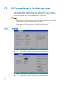
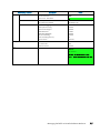
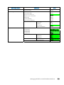
7.3
BIOS
7.3.1
7.3.2
7.3.3
7.3.4
7.3.5
7.3.6
7.3.7
7.3.8
7.3.9
Parameter Settings for NovaScale Rxxx Nodes........................................................... 7-4
Examples .............................................................................................................. 7-4
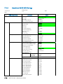
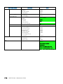
NovaScale R421 BIOS Settings ............................................................................... 7-5
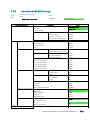
NovaScale R421 E1 BIOS Settings .......................................................................... 7-8
NovaScale R422 BIOS Settings ............................................................................. 7-10
NovaScale R422 E1 BIOS Settings ........................................................................ 7-13
NovaScale R423 BIOS Settings ............................................................................. 7-16
NovaScale R440 SATA BIOS Settings .................................................................... 7-19
NovaScale R440 SAS BIOS Settings ...................................................................... 7-21
NovaScale R460 BIOS Settings ............................................................................. 7-23
Glossary and Acronyms........................................................................................G-1
Index .................................................................................................................. I-1
Table of Contents
v
List of Figures
Figure
Figure
Figure
Figure
Figure
Figure
2-1.
2-2.
2-3.
3-1.
7-1.
7-2.
Example of IBS command topo action output................................................................ 2-22
Example of IBS command bandwidth action output....................................................... 2-24
Example of IBS command errors action output.............................................................. 2-25
OpenIB Diagnostic Tools Software Stack ....................................................................... 3-5
Example BIOS parameter setting screen for NovaScale R421 .......................................... 7-4
Example BIOS parameter setting screen for NovaScale R422 .......................................... 7-4
List of Tables
Table 2-1.
Table 3-1.
vi
Maintenance Tools...................................................................................................... 2-1
Available troubleshooting options for storage commands .............................................. 3-15
BAS5 for Xeon - Maintenance Guide
Chapter 1. Stopping/Starting Procedures
This chapter describes procedures for stopping and restarting Bull HPC cluster components,
which are mainly used for maintenance purposes.
The following procedures are described:
1.1
1.1.1
•
1.1 Stopping/Restarting a Node
•
1.2 Stopping/Restarting an Ethernet Switch
•
1.3 Stopping/Restarting a Backbone Switch
•
1.4 Stopping/Restarting the HPC Cluster
Stopping/Restarting a Node
Stopping a Node
Follow these steps to stop a node:
1.
Stop the customer’s environment. Check that the node is not running any applications
by using the SINFO command on the management node. All customer applications
and connections should be stopped or closed including shells and mount points.
2.
Un-mount the filesystem.
3.
Stop the node:
From the management node enter:
nsctrl poweroff <node_name>
This command executes an Operating System (OS) command. If the OS is not
responding it is possible to use:
nsctrl poweroff_force <node_name>
Wait for the command to complete.
4.
Check the node status by using:
nsctrl status <node_name>
The node can now be examined, and any problems which may exist diagnosed and
repaired.
Stopping/Starting Procedures
1-1
1.1.2
Restarting a Node
To restart a node, enter the following command from the management node:
nsctrl poweron <node_name>
Note:
If during the boot operation the system detects an error (temperature or otherwise), the
node will be prevented from rebooting.
Check the node status
Make sure that the node is functioning correctly, especially if you have restarted the node
after a crash:
•
Check the status of the services that must be started during the boot. (The list of these
services is in the /etc/rc.d file).
•
Check the status of the processes that must be started by a cron command.
•
The mail server, syslog-ng and ClusterDB must be working.
•
Check any error messages that the mails and log files may contain.
Restart SLURM and the filesystems
If the previous checks are successful, reconfigure the node for SLURM and restart the
filesystems.
1-2
BAS5 for Xeon - Maintenance Guide
1.2
Stopping/Restarting an Ethernet Switch
•
Power-off the Ethernet switch to stop it.
•
Power-on the Ethernet switch to start it.
•
If an Ethernet switch must be replaced, the MAC address of the new switch must be set
in the ClusterDB. This is done as follows:
1.
Obtain the MAC address for the switch (generally written on the switch, or found by
looking at DHCP logs).
2.
Use the phpPgAdmin Web interface of the DATABASE to update the switch MAC
address (http://IPadressofthemanagementnode/phpPgAdmin/ user=clusterdb and
password=clusterdb).
3.
In the eth_switch table look for the admin_macaddr row in the line corresponding to
the name of your switch. Edit and update this MAC address. Save your changes.
4.
Run a dbmConfig command from the management node:
dbmConfig configure --service sysdhcpd --force -nodeps
5.
Power-off the Ethernet switch.
6.
Power-on the Ethernet switch.
The switch issues a DHCP request and loads its configuration from the management node.
See:
Bull HPC BAS5 for Xeon Administrator’s Guide for information about how to perform
changes for the management of the ClusterDB.
1.3
Stopping/Restarting a Backbone Switch
The backbone switches enable communication between the cluster and the external world.
They are not listed in the ClusterDB. It is not possible to use ACT for their reconfiguration.
Stopping/Starting Procedures
1-3
1.4
Stopping/Restarting the HPC Cluster
1.4.1
Stopping the HPC Cluster
To stop the whole cluster in complete safety it is necessary to launch different stages in
sequence. The nsclusterstop script includes all the required stages.
1.
From the management node, run:
# nsclusterstop
2.
1.4.2
Stop the management node.
Starting the HPC Cluster
To start the whole cluster in complete safety it is necessary to launch different stages in
sequence. The nsclusterstart script includes all the required stages.
1.
Start the Management Node.
2.
From the Management Node, run:
# nsclusterstart
See:
Chapter 2 details the nsclusterstop/nsclusterstart commands and their associated
configuration files.
1-4
BAS5 for Xeon - Maintenance Guide
Chapter 2. Day to Day Maintenance Operations
2.1
Maintenance Tools Overview
This chapter describes a set of maintenance tools provided with a Bull HPC cluster.
These tools are mainly Open Source software applications that have been optimized, in
terms of CPU consumption and data exchange overhead, to increase their effectiveness on
Bull HPC clusters which may include hundred of nodes. The tools are usually available
through a browser interface, or through a remote command mode. Access requires specific
user rights and is based on secured shells and connections.
Tool
Function
Purpose
ConMan
ipmitool
Managing Consoles through Serial
Connection
2-2
nsclusterstop /
nsclusterstart
Stopping/Starting the cluster
2-5
nsctrl
Administration
Remote Hardware
Management CLI
Backup / Restore
Monitoring
Debugging
Testing
Page
2-7
Managing hardware (power on, power off,
reset, status, ping checking temperature,
changing bios, etc)
2-8
syslog-ng
System log Management
lptools
(lputils, lpflash)
Upgrading Emulex HBA Firmware (Host Bus
Adapter)
2-13
mkCDrec
Backing-up and restoring data
2-15
ibstatus, ibstat
Monitoring InfiniBand networks
2-18
IBS tool
Providing information about and configuring
InfiniBand switches
2-20
switchname
Monitoring Voltaire switches
2-30
lsiocfg
Getting information about storage devices
2-33
pingcheck
Checking device power state
2-36
ibdoctor/ibtracert
Identifying InfiniBand network problem
2-37
crash/proc/kdump
Runtime debugging and dump tool
2-40
postbootchecker
Making verifications on nodes as they start
2-42
Table 2-1.
2-8
Maintenance Tools
Day to Day Maintenance Operations
2-1
2.2
Maintenance Administration Tools
2.2.1
Managing Consoles through Serial Connections (conman, ipmitool)
The serial lines of the servers are the communication channel to the firmware and enable
access to the low-level features of the system. This is why they play an important role in the
system init surveillance, or in taking control if there is a crash or a debugging operation is
undertaken.
The serial lines are brought together with Ethernet/Serial port concentrators, so that they
are available from the Management Node.
•
ConMan can be used as a console management tool.
See 2.2.1.1 Using ConMan.
•
ipmitool allows you to use a Serial Over Lan (SOL) link.
See 2.2.1.2 Using ipmi Tools.
Note:
Storage Units may also provide console interfaces through serial ports, allowing
configuration and diagnostics operations.
2.2.1.1
Using ConMan
The ConMan command allows the administrator to manage all the consoles, including
server consoles and storage subsystem consoles, on all the nodes. It maintains a connection
with all the lines that it administers. It provides access to the consoles and uses a logical
name. It supports the key sequences that provide access to debuggers or to dump captures
(Crash/Dump).
ConMan is installed on the Management Node.
The advantages of ConMan on a simple telnet connection are as follows:
•
•
•
•
Symbolic names are mapped per physical serial line.
There is a log file for each machine.
It is possible to join a console session or to take it over.
There are three modes for accessing the console: monitor(read-only), interactive(readwrite), broadcast(write only).
Syntax:
conman <OPTIONS> <CONSOLES>
2-2
-b
Broadcast to multiple consoles (write-only).
-d HOST
Specify server destination. [127.0.0.1:7890]
-e CHAR
Specify escape character. [&]
-f
Force connection (console-stealing).
BAS5 for Xeon - Maintenance Guide
-F FILE
Read console names from file.
-h
Display this help file.
-j
Join connection (console-sharing).
-l FILE
Log connection output to file.
-L
Display license information.
-m
Monitor connection (read-only).
-q
Query server about specified console(s).
-Q
Be quiet and suppress informational messages.
-r
Match console names via regex instead of globbing.
-v
Be verbose.
-V
Display version information.
Once a connection is established, enter "&." to close the session, or "&?" to display a list
of currently available escape sequences.
See the conman man page for more information.
Examples:
•
To connect to the serial port of NovaScale bull47, run the command:
conman bull47
Configuration File:
The /etc/conman.conf file is the conman configuration file. It lists the consoles managed by
conman and configuration parameters.
The /etc/conman.conf file is automatically generated from the ClusterDB information. To
change some parameters, the administrator should only modify the /etc/conman-tpl.conf
template file, which is used by the system to generate /etc/conman.conf. It is also possible
to use the dbmConfig command. See the Cluster Data Base Management chapter for more
details.
See the conman.conf man page for more information.
Note:
The timestamp parameter, which specifies the watchdog frequency, is set to 1 minute by
default. This value is suitable for debugging and tracking purposes but generates a lot of
messages in the /var/log/conman file. To disable this function, comment the line
SERVER timestamp=1m in the /etc/conman-tpl.cfg file.
Day to Day Maintenance Operations
2-3
2.2.1.2
Using ipmi Tools
The ipmitool command provides a simple command-line interface to the BMC (Baseboard
Management Controller).
To use SOL (Serial Over Lan) interface, run the following command:
ipmitool –I lanplus –C O –U <BMC_user_name> –P <BMC_password>
–H <BMC_IP_Address> sol activate
BMC_user_name, BMC_password and BMC_IP_Address are values defined during the
configuration of the BMC and are taken from those in the ClusterDB. The standard values
for user name/password are administrator/administrator.
ipmitool Command Useful Options
•
To start a remote SOL session (to access the console):
ipmitool -I lanplus –C 0 -H <ip addr> sol activate
•
To reset the BMC and return to BMC shell prompt:
ipmitool -I lanplus -C 0 -H <ip addr> bmc reset cold
•
To edit the FRU of the machine:
ipmitool -H <ip addr> fru print
•
To edit the network configuration:
ipmitool -I lan -H <ip_addr> lan print 1
•
To trigger a dump (signal INIT):
ipmitool -H <ip addr> power diag
•
To power down the machine:
ipmitool -H <ip addr> power off
•
To perform a hard reset:
ipmitool -H <ip addr> power reset
•
To display the events recorded in the System Event Log (SEL):
ipmitool -H <ip addr> sel list
•
To display the MAC address of the BMC:
ipmitool -I lan -H <ip addr> raw 0x06 0x52 0x0f 0xa0 0x06 0x08 0xef
Note: If –H is not specified, the command will address the BMC of the local machine.
•
To know more about the ipmitool command, enter:
ipmitool –h
2-4
BAS5 for Xeon - Maintenance Guide
2.2.2
Stopping/Starting the Cluster (nsclusterstop, nsclusterstart)
The nsclusterstop/nsclusterstart scripts are used to stop or start the whole HPC cluster. These
scripts launch in sequence the various stages making it possible to stop/start the cluster in
full safety. For example, the stop process includes the following main steps:
•
checking the various equipment,
•
stopping the file systems (Lustre for example),
•
stopping the storage devices,
•
stopping the nodes, except the Management Node(s).
nsclusterstop and nsclusterstart use two configuration files:
/etc/clustmngt/nsclusterstart.conf and /etc/clustmngt/nsclusterstop.conf files whose values
can be changed. The --file option allows you to specify another configuration file. These
files define:
•
the delay parameters between the different stages required to stop/start the cluster
•
the sequence in which the group of nodes should be stopped/started. You can run
dmbGroup show to display the configured groups.
Usage:
/usr/sbin/nsclusterstop [-h] | [-f, --file <filename>]
/usr/sbin/nsclusterstart [-h] | [-f, --file <filename>]
Options:
--file <filename>, -f Specify a configuration file (default:
/etc/clustmngt/nsclusterstart.conf or
/etc/clustmngt/nsclusterstop.conf).
-h
Display nsclusterstart/nsclusterstop help.
--only_test , -o
Display the commands that would be launched according to the
specified options. This is a testing mode, no action is performed.
--verbose, -v
Verbose mode.
Configuration files:
/etc/clustmngt/nsclusterstart.conf
##################################################################
#
# First Part is used to control the power supply of DDN and servers
#
##################################################################
# time to wait for all diskarrays ok, before powering the powerswitches on
disk_arrays_StartDelay = 300
Day to Day Maintenance Operations
2-5
# time to wait for all powerswitches being ON after a poweron
couplets_StartDelay = 60
# time to wait after poweron for all servers being effectively operational
servers_StartDelay = 480
##################################################################
#
# Following part is used to control the order to start nodes groups
#
##################################################################
# GROUP <nb simultaneous poweron> <time to wait> <period to wait> <time to
wait after this GROUP>
IO 5 1 5 5
META 5 1 5 5
COMP 5 1 5 5
/etc/clustmngt/nsclusterstop.conf
##################################################################
#
# First Part is used to control the power supply of DDN and servers
#
##################################################################
# time to wait after poweroff for all servers being effectively down
servers_StopDelay = 180
# time to wait for ddn processing shutdown
ddnShutdown_Time = 180
# time to wait after poweroff for all powerswitches being OFF
couplets_StopDelay = 30
##################################################################
#
# Following part is used to control the order to stop nodes groups
#
##################################################################
# GROUP <nb simultaneous poweron> <time to wait> <period to wait> <time to
wait after this GROUP>
COMP 5 1 5 5
META 5 1 5 5
IO 5 1 5 5
2-6
BAS5 for Xeon - Maintenance Guide
2.2.3
Managing hardware (nsctrl)
The nsctrl command carries out various tasks related to hardware. This command must be
run from the Management Node. The tasks can be performed on any type of node
(Compute Node, I/O Node, etc.) except the Management Node.
Usage:
/usr/sbin/nsctrl [options] <action> [<nodes>]
General Options:
--debug
Debug mode (more than verbose).
--dbname name
Specify database name.
--force, -f
Do not ask for confirmation or state checking.
--group, -g
Specify a group of nodes. You can use the dbmGroup show command
to display the defined groups.
--help, -h
Display nsctrl help.
--interval, -i
Specify the number of nsm calls before waiting the period defined by
the --time option.
--jobs, -j
Number of simultaneous nsm actions (for example, with -j 5 you can
run 5 simultaneous nsmpower processes). Default = 30.
--only_test, -o
Display the NS Commands that would be launched according to the
specified options and action. This is a testing mode, no action is
performed.
--time, -t
Time to wait after the number of nsm calls defined by the --interval
option.
--verbose, -v
Verbose mode.
Specifying nodes:
The nodes are specified as follows: basename[i,j-k] .
If no nodes are explicitly specified, nsctrl uses the nodes defined by the --pap or --group
option.
Actions:
poweron
poweroff
poweroff_force
reset
status
ping
Day to Day Maintenance Operations
2-7
Examples:
Note: In the following examples the –o option (--only_test) is used to display which NS
Commands would be launched for the specified action.
•
To power off node ns1, enter:
# nsctrl -o poweroff_force ns1
ns1 : /usr/NSMasterHW/bin/nsmpower.sh -a off_force -m ipmilan
-H ns1 -u user2
•
To ping node ns1, enter:
# nsctrl -o ping ns1
ns1 : ping -c 1
2.2.4
ns1
Remote Hardware Management CLI (NS Commands)
The Remote Hardware Management CLI (Command Line Interface) is a set of commands
that perform hardware tasks on Bull HPC, these are also known as NS Commands. These
commands provide the administrator with an easy way to automate scripts to power on/off
and to get hardware information about the nodes.
2.2.5
Managing System Logs (syslog-ng)
For security and tracking purposes, and also to decrease the amount of administration
work resulting from the size of the cluster, all the system logs are centralized on the
Management Node. There are two ways to send system log information to the
Management Node:
•
The logs are collected on each node, using standard mechanisms for archival and log
file permutation. Various utilities ensure compression, transfer and archival of these log
files on the Management Node in asynchronous mode. A centralized operation is
performed on the Management Node, in order to extract and search events according
to the criterion required for example date, type, gravity, and so on.
This asynchronous process facilitates curative actions for the incidents that have
occurred on the cluster.
•
Some events are immediately reported to the Management Node. Filters are used,
which specify the type and gravity level of the events that have to be transferred
immediately.
This synchronous process instantaneously gives the administrator a global view of
system events.
syslog-ng (Syslog New Generation) is the powerful system log manager used on Bull HPC
clusters to manage cluster system logs and includes the following features:
•
•
•
•
2-8
The ability to filter messages based on content using regular expressions.
Encoding and authentication of the network traffic.
Forwarding logs using TCP and UDP protocols.
Log compression.
BAS5 for Xeon - Maintenance Guide
2.2.5.1
Configuring syslog-ng
syslog-ng is installed on the cluster using the default configuration. The scripts used to
transfer log files are also installed. The administrators can modify the default configuration
according to their needs.
The /etc/syslog-ng/syslog-ng.conf file contains the configuration parameters for syslog-ng.
This file is divided into five sections:
options section
General options
source section
Source events
destination section
Log destinations
filter section
Filter definitions
log section
Actions to be performed on messages
options Section
Any general parameters may be configured in the options section. An example is below:
# Start of options area
options {
sync (0);
# Number of events before writing in the logs
time_reopen (10);
# Wait 10s before reconnecting if the connection
failed. Used when logs are centralized through network
#time_reap (number); # Closes a log file that is not accessed after
"number" seconds
log_fifo_size (1000); # number of event lines stored, before writing
them.
Enables events to be taken quickly into account
and to free the process that has generated them.
long_hostnames (off);
use_dns (no)
# Usage of long names
# Usage of DNS to find addresses
use_fqdn (no); # Usage of machine short name
owner("root"); # logs owner
group("root"); # logs group
perm("644");
# logs rights mask
keep_hostname (yes); #
create_dir (yes);
use_time_recv(no);
written in the logs
# Create directories for log storage
# Local time will be used instead of the time
#gc_idle_threshold(100); # The garbage collector is started after 100
events if syslog-ng is inactive.
#gc_busy_threshold(100); # The garbage collector is started after
3000 events if syslog-ng is active.
};
Day to Day Maintenance Operations
2-9
source Section
The source section defines the log source from the following: network, local files,
peripheral, pipe, stream.
Syntax:
source <identifier>
{source-driver(params); source-driver(params); etc.};
For example, the following lines are suitable for a Linux system. They enable the /dev/log
stream to be read and also to receive syslog-ng internal messages and to handle kernel
starting messages:
source src {
unix-stream("/dev/log");
internal();
file("/proc/kmsg");
};
Possible sources are as follows:
unix-stream(<filename>)
Stream pipes (used in Linux).
file(<filename>)
File data (Linux kernel messages for example).
pipe(<filename>)
Named pipes (for interfacing with Nagios for example).
tcp(<ip>,<port>) and udp(<ip>,<port>)
To listen on an address and a port.
internal()
syslog-ng internal messages.
destination Section
This section defines the destination of the logs.
Syntax:
destination <identifier>
{ destination-driver(params); destination-driver(params); etc.};
The possible destinations are the following ones:
file(<filename>)
To send to a file.
tcp(<ip>,<port>) and udp(<ip>,<port>)
To send the logs on the network to another machine.
unix-stream(<filename>)
To send to stream pipes (used in Linux).
userttyr(<user>)
To send to the <user > consoles, but only if this user is
connected. You can use the "*" character to specify that the
messages have to be sent to all users.
program(<commandtorun>) To send towards a program.
2-10 BAS5 for Xeon - Maintenance Guide
Examples :
You can specify several destination directives in a destination section, as in the following
example:
destination debug {file("/var/log/debug.log"); };
destination messages {file("/var/log/messages.log"); };
destination console {usertty("root"); };
destination xconsole {pipe("/dev/xconsole"); };
destination mail2admin {program("/usr/bin/MailToAdmin"); };
destination full{
file("/dev/tty12");
file("/var/log/full.log" log_fifo_size(2000));
};
Note: You can add specific options such as log_fifo_size(2000) as shown in the
example above.
In the following example, all the logs will be sent to the Management Node, whose
address is 192.168.0.100:
destination central_log {tcp ("192.168.0.100" port(514); }
Using Macros:
It may be useful to use macros to set intelligible names for your destination files. Predefined
macros exist, such as FACILITY, PRIORITY or LEVEL, DATE, FULLDATE, ISODATE, YEAR,
MONTH, DAY, HOUR, MIN, SEC, FULLHOST, HOST. Some examples are below:
destination full {
file("/dev/tty12");
file("/var/log/full_$DAY-$MONTH-$YEAR.log"
owner("root")
group("adm")
perm(0640));
};
destination hosts {
file("/var/log/HOSTS/$HOSTS/$FACILITY/$YEAR/$MONTH/$DAY/$FACILITY$YEAR
$MONTH$DAY"
owner("root")
group("adm")
perm(0600)
dir_perm(0700)
create_dirs(yes));
};
Note: Do not forget to remove or archive older files regularly.
Day to Day Maintenance Operations 2-11
filter Section
This section describes the filtering mechanism for events.
Syntax:
filter <identifier> {expression; };
The filters are defined by the following keywords:
facility(facility[,facility])
To filter by type.
level(pri[,pri1, .. pri2 [,pri3]])
To filter by priority or level.
program(regexp)
To filter by the name of the program that has generated
the message.
host(regexp)
To filter by the regular expression of the name of the host
that has sent the message.
match(regexp)
To filter by a regular expression.
filter(filtername)
To use another filter.
All keywords may be used several times. The expressions can contain the AND, OR and
NOT operators.
Examples:
filter f_iptables { match("IN=.*OUT=.*MAC=.*"); };
filter f_snort { match("snort: "); };
filter f_full { not filter(f_snort) AND NOT filter(f_iptables); };
filter f_messages { level(info..warn) AND NOT facility(auth, authpriv,
mail, news); };
log Section
In this section you define how the messages will be processed using source, destination
and filters commands defined in the previous sections.
Syntax:
log { source(s1); source(s2); ...
filter(f1); filter(f2); ...
destination(d1); destination(d2);
flags(flag1[, flag2...]; };
Examples:
log { source(src);
filter(f_news); filter(f_notice);
destination(newsnotice);
};
log { source(src);
destination(full);
};
2-12 BAS5 for Xeon - Maintenance Guide
2.2.6
Upgrading Emulex HBA Firmware with lptools
lptools is a set of two utilities for upgrading Emulex HBA firmware. These two utilities are:
•
lputil: low level tool used to interact with Emulex HBA
•
lpflash: high level script used to upgrade firmware of a set of Emulex HBA.
Emulex driver (lpfc module) has to be loaded when using lptools (check with lsmod).
Firmware updates are available from Emulex Web site.
On a node, you can get the current FW level from all the Emulex HBA using the lsiocfg tool
(“getting information about storage devices”).
Warning: Be sure that FC devices are not being used when upgrading the Emulex HBA
firmware.
2.2.6.1
lputil
This low level tool should not be used in standalone mode. Please refer to on-line help
when using this tool.
2.2.6.2
lpflash
lpflash flashes Emulex HBAs with the specified firmware file. lpflash may be used to
upgrade in one shot all the HBAs on a server.
Syntax:
lpflash <-m LP_Model -f path_to_firmware [-v]> | <-h> | <-V>
Flags:
-m model
Emulex HBA model to flash (case insensitive)
-f file
firmware file
-v
verbose mode
-h
displays help
-V
displays version
Example:
lpflash –m lp11000 –f
/tmp/bd210a7.all
This command will upgrade all LP11000 HBA to 2.10A7 firmware.
Day to Day Maintenance Operations 2-13
2.2.6.3
Upgrade Emulex Firmware on Multiple Nodes
Running the pdcp / pdsh commands, Emulex firmware can be upgraded in one shot on a
set of nodes:
•
use pdcp to copy the new firmware file on all the nodes
•
use pdsh to run lpflash on these nodes.
Example:
The following commands copy the Emulex firmware file on to nodes node1, node2 and
node3, and then upgrade all Emulex LP11000 HBA on these nodes with firmware
2.10A7:
pdcp –w “node1,node2,node3” bd210a7.all /tmp/
pdsh –w “node1,node2,node3” lpflash –m lp11000 –f /tmp/bd210a7.all
2-14 BAS5 for Xeon - Maintenance Guide
2.3
Saving and Restoring the System (mkCDrec)
To save and restore the Management Node system, use the mkCDrec (make CD-ROM
recovery). mkCDrec is an Open Source tool used to create a bootable system image which
includes Linux system save. The image is used to restore the system after a problem, such
as a disk crash or system intrusion, has occurred.
The backups are generally on CD-ROM or DVD-ROM, or on an off-line disk, preferably in
read-only mode, or on NFS mounted disk or tape. The backups are protected and are
inaccessible for non-authorized users.
The mkCDrec tool can be used for the following functions:
•
To restore software. After booting from the mkCDrec CD-ROM or DVD-ROM, the
/etc/recovery/start-restore.sh script will do the following:
− Restore the complete system after a problem of some kind, for example a disk
crash or a system intrusion.
− Restore a particular disk using the backup source.
− Restore a backup of a disk onto a new (bigger) disk in the system.
•
To make multiple backup copies.
•
As a rescue tool, for example to do fsck operations or to diagnose what's wrong with
the system. See the mkCDrec utilities in order to add more tools to your rescue CDROM or DVD-ROM.
•
To “clone” a disk to another disk even when the target disk is smaller in size than the
original disk, as long as there is room for the data. The clone-dsk.sh script will
calculate the partition layout for you.
•
It is possible to make multi-volume CD-ROMs so backups can be split up. It is also
possible to backup all the data required for booting onto a CD-ROM, in order to
obtain a bootable CD-ROM, and to save other data onto TAPE.
•
To restore a single file system to an existing partition, using the restore-fs.sh command.
The user can select the target file system type which has to be formatted. The
command has no arguments.
•
To set-up or migrate to LVM, Software RAID, or another type of file system if the kernel
permits it.
•
To increase or decrease the partition size with the help of the mkCDrec utilities.
Note:
mkCDrec is designed for system backups. It is not the objective of mkCDrec to backup all
system data and it is recommended to regularly backup all your data using another
method.
A typical example of usage is to run mkCDrec every night for a system and store the ISO
images on another system via NFS. In case of a problem it will be possible to burn the
saved image onto a CD-ROM/DVD-ROM and then to restore the system.
What follows is an overview about configuring and using mkCDrec. For more information
please refer to http://mkcdrec.sourceforge.net
Day to Day Maintenance Operations 2-15
2.3.1
Configuring mkCDrec
The /var/opt/mkcdrec/Config.sh file contains the configuration parameters for mkCDrec.
All parameters have a default value. However, it is recommended that the following values
are checked, either to verify that they fit your needs, or to define your own values in order
to generate a coherent, but not too large, system backup.
BURNCDR
(Y or N)
”Y” means that the CD-ROM/DVD-ROM will be burned directly from
the machine.
”N” means that ISO images of the CD-ROM/DVD-ROM will be
created.
ISOFS_DIR
Path of the temporary directory used before creating the ISO images.
Ensure that this directory is large enough to store the contents of a CDROM/DVD-ROM.
TMP_DIR
Path of the temporary directory used by mkCDrec.
DVD_DRIVE
(1 or 0) Set “0” to create CD-ROM backups or “1” to create DVD
backups.
MAXCDSIZE
Maximum size of the created images (in kbs).
Example: 4200000 for DVD-ROM, 620000 for CD-ROM.
CDREC_ISO_DIR
Path of the directory used to store the ISO backups. Ensure that this
directory is large enough to store all the backups.
EXCLUDE_LIST
List of the directories and files to be saved in the backup. Choose only
what seems important to save, in order to obtain a backup of a
reasonable size.
BOOTARCH
Defines the architecture of the system to backup (x86, ia64, etc.).
Check that the value fits the system.
The configuration can be performed using the Webmin interface:
http://hostname:10000/mkcdrec/
2.3.2
Creating a Backup
Perform these operations on the Management Node.
1.
Log on as root user, in single mode.
2.
Stop the activity on the Management Node; the ClusterDB must not be used during the
backup operation.
3.
Go to the mkCDrec base directory, by default this is /var/opt/mkcdrec:
cd /var/opt/mkcdrec
4.
Check that the system is operational for mkCDrec:
make test
2-16 BAS5 for Xeon - Maintenance Guide
mkCDrec displays warning messages if it has detected that some elements are missing
for the backup. If this happens, perform the appropriate corrections and restart make
test until the test is successful.
5.
Launch the backup operation:
make
A menu is displayed:
Enter your selection:
1) Create rescue CD-ROM only (no backups)
2) Create ISO backup images in /tmp
(to burn on CDROM or DVD)
3) Create backup on disk
(mounted harf disk, NFS mount point, SMB mount point)
4) Create backup on tape device /dev/nst0
5) Quit
Please choose from the above list [1-5]:
Select one of the displayed options (1 to 5).
Follow the instructions displayed on the screen.
When the operation is finished, ISO images ready for burning will be created in the
directory specified in the configuration file (CDREC_ISO_DIR parameter).
Note: The mkcdrec.log file can be checked in case of problem.
Before burning a CD/DVD you can check the contents of the ISO image using the
following command:
mount –o loop /backup/ISO/Cdrec.iso/mnt
2.3.3
Restoring a System
To restore a system, boot on the first CD-ROM/DVD-ROM, then run the command:
/etc/recovery/start-restore.sh
Follow the instructions displayed on the screen.
When the restore is completed, enter the reboot command. A new EFI boot entry is
created.
Day to Day Maintenance Operations 2-17
2.4
2.4.1
2.4.1.1
Monitoring Maintenance Tools
Checking the status of InfiniBand Networks (ibstatus, ibstat)
ibstatus Command
ibstatus displays basic information obtained from each InfiniBand driver for the local
adapter included in an InfiniBand network.
Normal output includes LID, Subnet Manager LID, port state (UP or DOWN), port physical
state and the link width in terms of transfer rate. -v enable verbose mode which includes all
sysfs supported parameters for the port interface and port.
Syntax:
ibstatus [-h] [devname[:port]]...
Examples:
•
To display status of all IB ports, enter:
ibstatus
•
To display status of mthca1 ports, enter:
ibstatus mthca1
•
To show status of specified ports, enter:
ibstatus mthca1:1 mthca0:2
Output example for a mthca dual port HCA
Infiniband device 'mthca0' port 1 status:
default gid:
fe80:0000:0000:0000:0008:f104:0397:7ca5
base lid:
0x0
sm lid:
0x0
state:
1: DOWN
phys state:
2: Polling
rate:
2.5 Gb/sec (1X)
Infiniband device 'mthca0' port 2 status:
default gid:
fe80:0000:0000:0000:0008:f104:0397:7ca6
base lid:
0x2d
sm lid:
0x3
state:
4: ACTIVE
phys state:
5: LinkUp
rate:
10 Gb/sec (4X)
2-18 BAS5 for Xeon - Maintenance Guide
2.4.1.2
ibstat Command
ibstat works in a similar fashion to the ibstatus utility but is implemented as a binaries and
not a script, and is more useful than ibstatus as more detailed information is provided.
It includes options to list Channel Adapters and/or Ports.
Syntax:
ibstat [-d(ebug) -l(ist_of_cas) -p(orts_list) -s(hort)] <ca_name> [portnum]
ibstat command examples:
•
To display status of all IB ports, enter:
ibstat
•
To display status of mthca1 ports, enter:
ibstat mthca1
•
To show status of specified ports, enter:
ibstat mthca1 2
•
To list the port guids of mthca0, enter:
ibstat -p mthca0
•
To list all CA names, enter:
ibstat -l
Day to Day Maintenance Operations 2-19
2.4.2
Diagnosing InfiniBand Fabric Problems (IBS tool)
This tool is used from the Management Node to diagnose problems for InfiniBand fabric
using the cluster switch topology information contained in the NetworkMap.xml file, and
the error checking counters contained in the PortCounters.csv file. Alternatively, an IBS
database, IBSDB, containing all the switch information can be created and then used as
the data source to diagnose the problems
Command syntax
ibs -a <action> [-hvCNE] [-l-|-s <switch>] [-f <networkmap>] [-c <counters>]
The following options are available for the ibs command:
-h
Help file
-v
Verbose mode
-C
Disable colored text output
-a
Action (one of: topo, bandwidth, errors, config, group, dbpopulate,
availability, dbcreate, dbdelete, dbupdate, dbupdatepc).
OFED related options
When working from the cluster Management Node, and provided this node is fitted with
an InfiniBand adapter that is connected to an InfiniBand interconnect, it is recommended
that the –N and –E options are used as the OFED software view of the cluster is more
reliable than that provided by data taken directly from the switch.
-N
Query the IB subnet manager to obtain and update the hostname details.
-E
Query the IB subnet manager to obtain and update data using the error and
traffic counters.
Data related options
By default IBS analyses the data contained in the IBSDB database unless the –s or –l flags
are used. This default mode is known as ‘database mode’.
-s <switch>
‘Connected mode’. Connect to the switch specified by its hostname or IP
address and then retrieve the NetworkMap.xml and PortCounters.csv files
for this switch.
-l
‘Local mode’. Use the NetworkMap.xml and PortCounters.csv files that are
available locally or that are specified by the -f and -c flags for the analysis.
These files can then be analysed separately on a machine which is not part
of the cluster. However, as stated above it is better to work within the
OFED stack using the –N and –E options to obtain the latest data.
2-20 BAS5 for Xeon - Maintenance Guide
2.4.2.1
-f filename
Specify the file to be used when loading or saving the network map file,
NetworkMap.xml. When used in conjunction with the -s switch option, the
file downloaded from the switch will be saved to file <filename>. When
used in conjunction with the -l flag, the specified file will be used as the
input file.
-c filename
Specify the file to be used when loading or saving the port counters file
(PortCounters.csv file). When used in conjunction with the -s switch option,
the file downloaded from the switch will be saved to the file <filename>.
When used in conjunction with the -l flag, the specified file will be used as
the input file.
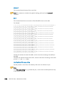
IBS command actions
topo
The topo action for the – a option provides detailed topology details for the switch.
ibs -s <switch_name> -a topo -NE
This will give output that includes a description of the switches, the hostnames, the GUID for
the Nodes, the LID for the Nodes, the physical location of the switches. The port details,
including any errors, are shown in the bottom half of the screen for both local ports and for
ports which are connected to remotely – see the screen example on the next page:
Day to Day Maintenance Operations 2-21
Figure 2-1. Example of IBS command topo action output
2-22 BAS5 for Xeon - Maintenance Guide
Use the command below to obtain the fabric topology using the data stored in the IBS
database. The hostnames and traffic counters are updated using the OFED tools:
ibs -a topo -NE
Use the command below to dump the fabric topology using the local map file
test/NetworkMap.xml and test/portcounters.csv. The data read from these files is updated
using the OFED tools:
ibs -l -f test/NetworkMap.xml -c test/portcounters.csv -a topo -NE
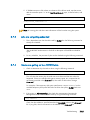
bandwidth
The syntax for the bandwidth action is shown below. This action is very useful when
benchmarking in order to monitor the performance of switch and to identify any
bottlenecks.
ibs -s <switch_name> -a bandwidth -NE
Details of packets sent and received for the switch for both local and remote connections
are displayed, as shown in Figure 2-2.
errors
The errors action can be used to produce a short report containing details of the faulty links
for a switch. This is very useful for troubleshooting and will help to pinpoint any problems
for the interconnects.
ibs -s <switch_name> -a errors -NE
This will give output, similar to that shown in Figure 2-3. EPM indicates the error rate in the
form of Errors per Million packets sent.
See FAQ ID – F10040 “How to debug and clear InfiniBand fabric errors using FVM PM
Counters CSV file?” available from www.voltaire.com for details of the different Port
Counter error messages.
Day to Day Maintenance Operations 2-23
Figure 2-2. Example of IBS command bandwidth action output
2-24 BAS5 for Xeon - Maintenance Guide
Figure 2-3. Example of IBS command errors action output
Day to Day Maintenance Operations 2-25
config
This action manually creates the instruction sequence needed to configure the hostname
mapping for a switch.
Note: This option only applies to Voltaire switches which use 4.0 or later firmware
versions.
ibs -s <switch_name> -vNE -a config
group
This action generates the group.csv file that includes the hostname mapping configuration
details for all the switches, this can then be imported into a switch in order to configure it.
For large clusters, this is quicker than running the config action (as detailed above), to
generate and import the cluster switch configuration details into a switch.
Note:
This option only applies to Voltaire switches which use version 4.0 or later firmware.
ibs -s iswu0c0-0 -a group
While the command is being carried out a message similar to that below will appear:
Successfully generated configuration file group.csv
To update a managed switch, proceed as follows:
- Log onto the switch
- Enter the 'enable' mode
- Enter the 'config' menu
- Enter the 'group' menu
- Type the following command: group import /home/user/path
2.4.2.2
IBSDB Database
It is possible to create a database, which includes all the hardware and InfiniBand traffic
details for all the switches, with the IBS tool. This database is specific to InfiniBand
hardware.
The following commands apply to the IBSDB Database.
dbcreate
To create an empty, new IBS database (ibsdb) use the dbcreate command. Only the
’postgres’ user is allowed to create an empty database.
postgres@admin$ ibs -a dbcreate
2-26 BAS5 for Xeon - Maintenance Guide
While the command is being carried out a message similar to that below will appear:
------------------------------------------------------------------------Looking for program createdb
using /usr/bin/createdb
Looking for program psql
using /usr/bin/psql
Creating database ibsdb
Done.
Loading table definitions into database ibsdb
Done.
-------------------------------------------------------------------------
dbdelete
To delete an IBS database (ibsdb) use the dbdelete command. Only the ’postgres’ user is
allowed to delete an empty database.
postgres@admin$ ibs -a dbdelete
While the command is being carried out a message similar to that below will appear:
-----------------------------------------------------------------------Looking for program dropdb
Deleting database ibsdb
using /usr/bin/dropdb
Done.
------------------------------------------------------------------------
dbpopulate
Use the dbpopulate action to populate a new database. In the example below data is
supplied from the iswu0c0-0 managed switch from the Management Node, and the
hostnames and traffic counters are populated using the OFED tools:
ibs -s iswu0c0-0 -a dbpopulate –vNE
While the command is being carried out a message similar to that below will appear:
---------------------------------------------------------------------------------------Connecting to switch iswu0c0-0
Done.
Sending request for file NetworkMap.xml
Done.
Getting response header from switch iswu0c0-0
Done.
Downloading NetworkMap.xml
Creating IB hosts
HCA: 21, ASICS: 0, ISR9024: 3, ISR9096: 0, ISR9288/2012: 0, total: 24
Populating boards
No board found.
Populating switch chassis with boards
boards: 0, chassis: 0
Assigning ports to IB hosts
assigned: 74, total: 74
Connecting ports
assigned: 37 pairs, total: 37 pairs.
Looking for program smpquery
using /usr/local/ofed/bin/smpquery
Updating hostnames using OFED smpquery
updated: 24, failed: 0, total: 24
Looking for program perfquery
using /usr/local/ofed/bin/perfquery
Updating port counters using OFED perfquery
updated: 74, failed: 0, total: 74
Assigning portcounters
assigned: 74, not assigned: 0, total: 74
Connecting to database clusterdb on host localhost:5432
Done.
Updating equipment localisation from database clusterdb
24 localisations updated.
Updating equipment IP addresses from database clusterdb
24 IP addresses updated.
Updating switch IDs from database clusterdb
21 switch IDs updated.
Connecting to database ibsdb on host localhost:5432
Done.
Day to Day Maintenance Operations 2-27
Populating
Populating
Populating
Populating
Populating
Populating
Populating
table 'chassis' in database ibsdb
tables 'asic' and 'chassis' in database ibsdb
table 'board' in database ibsdb
table 'asic' in database ibsdb
table 'hca' in database ibsdb
tables 'asic_port' and 'hca_port' in database ibsdb
tables 'asic_portcounters' and 'hca_portcounters
0 chassis stored.
3 ISR9024 switch stored.
0 boards stored.
0 ASICs stored.
21 HCAs stored.
74 ports stored.
74 portcounters stored.
-----------------------------------------------------------------------------------------
dbupdate
Use the dbupdate action to update an existing IBSDB database.
In the example below the topology and traffic counter details for the iswu0c0-0 managed
switch from the Management Node, is updated using the OFED tools:
ibs -s iswu0c0-0 -a dbupdate -NE
In order to ensure that the data is always up to date, add the following line to the cron
table (using crontab -e).
*/10 * * * * PATH=/usr/local/ofed/bin:$PATH /usr/bin/ibs -s
iswu0c0-0 -a dbupdate -vNE >> /var/log/ibs.log 2>&1
The traffic and error counters as well as the InfiniBand equipment stored in the IBS
database will be refreshed every 10 minutes using the data supplied by the iswu0c0-0
switch
Note:
The user needs to know which switch is running the subnet manager as master for
InfiniBand clusters that include multiple managed switches. This switch should always be
the one that is specified as the argument of the -s flag. Assuming that the data is refreshed
by the cron daemon, then if another switch becomes the subnet manager master the data
details contained in the database would then be incorrect, as it would use data from what
is the slave switch as defined in the cron script.
Use the sminfo command as follows to know which subnet manager is running as the
master:
Output in a form similar to that below will be provided:
------------------------------------------------------------------------sminfo: sm lid 1 sm guid 0x8f1040041254a, activity count 544113 priority
3 state 3 SMINFO_MASTER
-------------------------------------------------------------------------
The guid that is identified can then be used to find the corresponding switch name in the
ibsdb ’chassis’ table.
2-28 BAS5 for Xeon - Maintenance Guide
dbupdatepc
Use the dbupdatepc action to update the port counters for an existing IBSDB database. Use
the command below:
ibs -a dbupdatepc -vNE
availability
Use the availability action to see which ports and links are available for the InfiniBand
interconnects. This action will not work unless the IBSDB database has been created and
populated.
ibs -s iswu0c0-0 -a availability
This will give results in a similar format to that below.
-----------------------------------------------------------------Active ports: 74
Active uplinks: 16
Active downlinks: 21
------------------------------------------------------------------
2.4.2.3
Return Values
IBS returns 0 for success. Any other value indicates a failure.
Day to Day Maintenance Operations 2-29
2.4.3
Monitoring Voltaire Switches (switchname)
Different options exist for monitoring and maintaining the performance of Voltaire switches.
To begin with enter the utilities menu as follows:
[user@host ~]# ssh enable@switchname
------------------------------------------------------------------------enable@switchname's password: voltaire
Welcome to Voltaire Switch switchname
Connecting
------------------------------------------------------------------------switchname # utilities
switchname (utilities)#
2.4.3.1
Resetting the counters
The counters (volume and errors) can be reset through the zero-counters command as
follows:
switchname (utilities) zero-counters
Zero All Counters
Zero lid 8 port 255 mask 0xffff
[ ... ]
2.4.3.2
Finding bad ports
The find_bad_ports command can be used to detect faulty ports:
switchname (utilities) find_bad_ports
------------------------------------------------------------------------Found bad link/port:
node_guid:.......................0008f10400411946
node_desc:.......................'ISR9024D Voltaire'
lid:.............................152
smlid:...........................8
Port 4
direct path from self switch: 0,1 4
-------------------------------------------------------------------------
2-30 BAS5 for Xeon - Maintenance Guide
2.4.3.3
Verifying the ports
The whole Infiniband fabric can be checked using the port-verify command as follows:
switchname (utilities) port-verify
----------------------------------------------------------------------#
# Topology file: generated on Thu Oct 4 20:19:24 2007
#
devid=0x5a31
switchguids=0x8f1040041254a
Switch 24 "S-0008f1040041254a"
# "ISR9024D-M Voltaire" smalid 8
[1] "S-0008f10400411946"[13] width 4X speed 5.0 Gbs
[2] "S-0008f10400411946"[14] width 4X speed 5.0 Gbs
[3] "S-0008f10400411946"[15] width 4X speed 5.0 Gbs
[ ... ]
devid=0x6282
hcaguids=0x2c9020024b940
Hca 2 "H-0002c9020024b940"
# "zeus8 HCA-1"
[1] "S-0008f1040041281e"[1] # lid 72 lmc 3 width 4X speed 5.0 Gbs
SUMMARY: NO PROBLEMS DETECTED.
-------------------------------------------------------------------------
2.4.3.4
Checking the port width
To ensure the best performance, check that the ports are running in 4x mode as follows:
switchname (utilities) width-check
-----------------------------------------------------------------------Verify / every error found - will be printed
lid 8 guid 0008f1040041254a ports 24
lid 160 guid 0008f1040041281e ports 24
lid 152 guid 0008f10400411946 ports 24
-------------------------------------------------------------------------
2.4.3.5
Dealing with a faulty port
When a faulty port is diagnosed, it can be disabled or reset using the port-manage
command, as below:
iswu0c0-0(utilities) port-manage
Description:
port-manage.sh is used to trigger a physical state change for the port specified. This is
useful when the active width/speed of a specific port must be changed without the cable
being reconnected.
Syntax:
port-manage.sh [-v] [-f] <-d|-e|-r> <LID> <PORT>
Day to Day Maintenance Operations 2-31
Options:
-v
Increase output verbosity level
-f
Force disabling or resetting a port even when the port is located on the
Access Path (path/way to the specific port)
-d lid port
Disable the port
-e lid port
Enable the port (set port state machine to polling state)
-r lid port
Reset the port
-S lid port
Reset the port and set Enabled Speed to SDR
-D lid port
Reset the port and set Enabled Speed to SDR/DDR
-h
Show this help
Example:
#port-manage.sh -r 17 21 (reset LID=17 PORT=21)
2-32 BAS5 for Xeon - Maintenance Guide
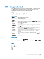
2.4.4
Getting Information about Storage Devices (lsiocfg)
lsiocfg is a tool used for reporting information about storage devices. It is mainly dedicated
to external storage systems (DDN and FDA disk arrays) and their dedicated Host Board
Adapters (Emulex FC adapters), but it can also be used with internal system storage (system
disks) and their Host Board Adapters tools.
Reported information is related to several inventories:
•
•
•
•
Host Board Adapters (-c flag)
Disks (-d flag)
Disk partitions (-p flag)
Disk usages.
Syntax:
According to needed information, lsiocfg can be used with options related to each
inventory.
•
lsiocfg [-P] [-v] -c [HBAs IDs]
Gives information about all SCSI controllers. If HBAs IDs are specified, only applies to
this list of HBAs.
•
lsiocfg [-P] [-v] -d [-u] [devices names]
Gives information about SCSI devices. [-u] has to be used to display non disk devices.
If devices are specified, only applies to this list of devices.
•
lsiocfg -p
Displays partitions.
•
lsiocfg [-P] [-v] -a
Dsplays all ( = -cdp).
•
lsiocfg [-r user] -n remote node [-P] [-v] [-c|-d|-a]
Gives information from remote node about controllers/disks.
•
lsiocfg -M [devices names]
Gives information about SCSI devices usage.
•
lsiocfg <-l|-L> <wwpn>
Reports WWPN owner. The –l flag uses /etc/wwn file, and the –L flag uses cluster
manager database.
•
lsiocfg <-w|-W>
Displays all WWPN owners. The –w flag uses /etc/wwn file, and the –W flag uses
cluster manager database.
General flags:
-P
No headers (before -[a|c|d] commands).
-v
Verbose (before -[a|c|d] commands). WWPN verbose information is
extracted from /etc/wwn file.
Day to Day Maintenance Operations 2-33
-h
Help message. Exclusive with other options.
-V
Display the version. Exclusive with other options.
Online help and a man page give information about lsiocfg usage.
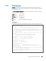
2.4.4.1
HBA Inventory
Using the lsiocfg HBA inventory option, you can get basic information about Host Board
Adapters:
•
model,
•
link up or down.
When getting HBA inventory in verbose mode, more details are available:
•
firmware levels,
•
serial number,
•
WWNN and WWPN (for fibre channel HBAs).
Example:
# lsiocfg -cv
----------------------------------------------------------------------------- HOST/CHANNEL INVENTORY ------------------------------------------Host
Driver
Unique_id Cmd/Lun HostQ State
Model
------------------------------------------------------------------------host0
host1
host2
mptbase
0
7
mptbase
1
7
lpfc
0
30
LINK_UP
LP11000
DRV=8.0.30_p1
FW=2.10A7 (B2D2.10A7)
Bus-Number=26
SN=VM53824841
Host-WWNN=20:00:00:00:c9:4b:e7:02
Host-WWPN=10:00:00:00:c9:4b:e7:02
FN=20:00:00:00:c9:4b:e7:02
speed=2 Gbit
host3 usb-storage 0
1
------------------------------------------------------------------------
2.4.4.2
Disks Inventory
Using the lsiocfg Disk inventory option, you can get basic information about the available
disks:
•
system location
•
vendor
•
state
•
disk size.
When getting the disk inventory in verbose mode, more details are shown:
•
model
•
serial number
2-34 BAS5 for Xeon - Maintenance Guide
firmware revision
WWPN (fiber channel devices).
•
•
# lsiocfg -dv
---------------------------------------------------------------------------- DISK INVENTORY ---------------------------------------------------Dev
Location Maj:Min Vendor
state
Size (MB) QueueDepth Lname
(location= Host:Channel:Id:LUN)
------------------------------------------------------------------------sdb
sdc
sda
sdd
sde
sdf
sdg
0:0:10:0 8:16
SEAGATE
MODEL=SEAGATE ST3300007LC
FWREV=0003
SERIAL=3KR0KTPH00007547TR0P
TRANSPORT=SPI
0:0:11:0 8:32
SEAGATE
MODEL=SEAGATE ST3300007LC
FWREV=0003
SERIAL=3KR0KTHM000075475NWC
TRANSPORT=SPI
0:0:9:0
8:0
SEAGATE
MODEL=SEAGATE ST3300007LC
FWREV=0003
SERIAL=3KR0JT0T00007548GUXA
TRANSPORT=SPI
2:0:0:0
8:48
DDN
MODEL=DDN S2A 8500
FWREV=5.20
SERIAL=02A820510D00
TRANSPORT=FC
WWPN=24:00:00:01:ff:03:02:a8
NAME=unknown
2:0:0:1
8:64
DDN
MODEL=DDN S2A 8500
FWREV=5.20
SERIAL=02A820540E00
TRANSPORT=FC
WWPN=24:00:00:01:ff:03:02:a8
NAME=unknown
2:0:0:2
8:80
DDN
MODEL=DDN S2A 8500
FWREV=5.20
SERIAL=03E020570F00
TRANSPORT=FC
WWPN=24:00:00:01:ff:03:02:a8
NAME=unknown
2:0:0:3
8:96
DDN
MODEL=DDN S2A 8500
FWREV=5.20
SERIAL=03E0205A1000
TRANSPORT=FC
WWPN=24:00:00:01:ff:03:02:a8
NAME=unknown
running
286102
31
running
286102
31
running
286102
31
running
10000
30
/dev/ldn.ddn0.13
running
125000
30
/dev/ldn.ddn0.14
running
10000
running
125000
30
30
/dev/ldn.ddn0.15
/dev/ldn.ddn0.16
------------------------------------------------------------------------
2.4.4.3
Disk Usage and Partition Inventories
These inventories give information about system and logical use of the devices. Such
information is mostly used for system administration needs.
Day to Day Maintenance Operations 2-35
2.4.5
Checking Device Power State (pingcheck)
The pingcheck command checks the power state (on or off) of the specified devices.
Usage:
pingcheck [options] --Type <device type> command devices
Options:
--dbname name
Specify database name.
--debug, -d
Debug mode (more than verbose).
--help, -h
Display pingcheck help.
--interval, -i
Specify the number of nsm calls before waiting the period defined by
the --time option.
--jobs, -j
Number of simultaneous nsm actions (for example, with -j 5 you can
run 5 simultaneous nsmpower processes). Default: 30.
--only_test, -o
Display the NS Commands that would be launched according to the
specified options and action. This is a testing mode, no action is
performed.
--time, -t
Time to wait after the number of nsm calls defined by the --interval
option.
--verbose, -v
Verbose mode.
Parameters
--Type <device type> Type of devices to be «pinged »: disk_array or server.
command
on or off.
devices
Specify the name of the devices, using the basename[i,j-k] or lc-like
syntax.
Examples:
•
The following command verifies that all the power supplies for disk_array 10 to 15 are
in on state and indicates those which are not.
pingcheck --Type disk_array on da[10-15]
•
The following command verifies that servers nova5 to 7 are in off state and indicates
those which are not.
pingcheck --Type server off nova[5-7]
2-36 BAS5 for Xeon - Maintenance Guide
2.5
2.5.1
Debugging Maintenance Tools
Modifying the Core Dump Size
By default the maximum size for core dump files for Bull HPC systems is set to 0 which
means that no resources are available and core dumps cannot be done. In order that core
dumps can be done the values for the ulimit command have to be changed.
For more information refer to the options for the ulimit command in the bash man page.
2.5.2
Identifying InfiniBand Network Problems (ibdoctor, ibtracert)
ibdoctor is Bull tool, which calls on the ibtracert, ibnetdiscover, and smpquery diagnostic
tools, whilst at the same time interfacing with the ClusterDB database so that any problems
in the InfiniBand network can be identified easily.
2.5.2.1
ibdoctor Command
ibdoctor may be used:
•
to identify where any problem adapters or nodes are located
•
to display communication paths, including bandwidth, between ports in a human
readable format.
Options:
-s <src_lid>
Use specified source lid.
-d <dst_lid>
Use specified destination lid.
-t
Trace route between <src_lid> and <dst_lid>.
-T
Report the fabric state over all known routes.
-h
Help.
Example:
•
To display status data for the path between two InfiniBand adapters with the local
identifiers 0x14 and 0x1e, enter:
ibdoctor -t -s 0x14 -d 0x1e
The output looks as follows:
OUT |
INTO|
OUT |
INTO|
bali4 HCA-1
ISR9024D Voltaire
ISR9024D Voltaire
bali23 HCA-1
|RACK2 M
|
|
|RACK2 K
•
|lid
|lid
|lid
|lid
0x14
0x11
0x11
0x1e
|port 1
|port 2
|port12
|port 1
|guid
|guid
|guid
|guid
0002c90200234144
0008f10400411da2
0008f10400411da2
0002c902002341b1
|state
|state
|state
|state
Active
Active
Active
Active
|width
|width
|width
|width
4X
4X
4X
4X
|rate
|rate
|rate
|rate
5.0
5.0
5.0
5.0
The –T option completes an exhaustive scan of the network, and traces and checks all
the possible routes between the adapters:
ibdoctor -T
The output looks as follows:
Day to Day Maintenance Operations 2-37
Gbps
Gbps
Gbps
Gbps
28 lids found
-------------------------------------------------------------------------------OUT | ISR9024D-M Voltaire|
| lid 0x1 | port 0 |guid 0008f10400411e54 |state
INTO | ISR9024D Voltaire |
| lid 0x2 | port 15 |guid 0008f10400411d6a |state
-------------------------------------------------------------------------------OUT | ISR9024D-M Voltaire|
| lid 0x1 | port 0 |guid 0008f10400411e54 |state
INTO | ISR9024D Voltaire |
| lid 0x11| port 13 |guid 0008f10400411da2 |state
OUT | ISR9024D Voltaire |
| lid 0x11| port 18 |guid 0008f10400411da2 |state
INTO | ISR9024D Voltaire |
| lid 0x3 | port 6 |guid 0008f10400411d70 |state
-------------------------------------------------------------------------------OUT | ISR9024D-M Voltaire|
| lid 0x1 | port 0 |guid 0008f10400411e54 |state
INTO | ISR9024D Voltaire |
| lid 0x2 | port 15 |guid 0008f10400411d6a |state
OUT | ISR9024D Voltaire |
| lid 0x2 | port 4 |guid 0008f10400411d6a |state
INTO | bali6 HCA-1
|RACK1 D| lid 0x4 | port 1 |guid 0002c90200234405 |state
-------------------------------------------------------------------------------OUT | ISR9024D-M Voltaire|
| lid 0x1 | port 0 |guid 0008f10400411e54 |state
INTO | ISR9024D Voltaire |
| lid 0x2 | port 16 |guid 0008f10400411d6a |state
OUT | ISR9024D Voltaire |
| lid 0x2 | port 5 |guid 0008f10400411d6a |state
INTO | bali7 HCA-1
|RACK1 E| lid 0x5 | port 1 |guid 0002c9020023440d |state
-------------------------------------------------------------------------------OUT | ISR9024D-M Voltaire|
| lid 0x1 | port 0 |guid 0008f10400411e54 |state
INTO | ISR9024D Voltaire |
| lid 0x2 | port 3 |guid 0008f10400411d6a |state
OUT | ISR9024D Voltaire |
| lid 0x2 | port 6 |guid 0008f10400411d6a |state
2.5.2.2
Active|width 4X| rate 2.5 Gbps
Active|width 4X| rate 5.0 Gbps
Active|width
Active|width
Active|width
Active|width
4X|
4X|
4X|
4X|
rate
rate
rate
rate
2.5
5.0
5.0
5.0
Gbps
Gbps
Gbps
Gbps
Active|width
Active|width
Active|width
Active|width
4X|
4X|
4X|
4X|
rate
rate
rate
rate
2.5
5.0
5.0
5.0
Gbps
Gbps
Gbps
Gbps
Active|width
Active|width
Active|width
Active|width
4X|
4X|
4X|
4X|
rate
rate
rate
rate
2.5
5.0
5.0
5.0
Gbps
Gbps
Gbps
Gbps
Active|width 4X| rate 2.5 Gbps
Active|width 4X| rate 5.0 Gbps
Active|width 4X| rate 5.0 Gbps
ibtracert Command
ibtracert uses Subnet Manager Protocols (SMP) to trace the path from a source GID/LID to
a destination GID/LID. Each hop along the path is displayed until the destination is
reached or a hop does not respond. By using the -mg and/or -ml options, multicast path
tracing can be performed between the source and destination nodes.
Syntax:
ibtracert [options] <src-addr> <dest-addr>
Flags
-n
Simple format; no additional information is displayed.
-m <mlid>
Show the multicast trace of the specified mlid.
Examples
•
To show trace between lid 2 and 23, enter:
ibtracert 2 23
•
To show multicast trace between lid 3 and 5 for mcast lid 0xc000, enter:
ibtracert -m 0xc000 3 5
Output:
The output for a command between two points is displayed in both hexadecimal format
and in human-readable format – as shown in the example below for the trace between the
two lids 0x22 and 0x2c. This is very useful in helping to identify any port/switch problems
in the InfiniBand Fabric.
2-38 BAS5 for Xeon - Maintenance Guide
ibtracert 0x22 0x2c
---------------------------------------------------------------------------->From ca {0008f10403979958} portnum 1 lid 0x22-0x22 "lynx13 HCA-1"
[1] -> switch port {0008f104004118e2}[8] lid 0x4-0x4 "ISR9024D Voltaire"
[13] -> switch port {0008f104004118e8}[16] lid 0x3-0x3 "ISR9024D-M Voltaire"
[21] -> switch port {0008f104004118e4}[13] lid 0x1-0x1 "ISR9024D Voltaire"
[4] -> ca port {0008f10403979985}[1] lid 0x2c-0x2c "lynx19 HCA-1"
To ca {0008f10403979984} portnum 1 lid 0x2c-0x2c "lynx19 HCA-1"
In short:
=> OUT lynx13 (lid 0x22 / port 1
=> INTO node switch (lid 0x4) / port 8
=> OUT node switch (lid 0x4) / port 13
=> INTO top switch (lid 0x3) / port 16
=> OUT top switch (lid 0x3) / port 21
=> INTO node switch (lid 0x1) / port 13
=> OUT node switch (lid 0x1) / port 4
=> INTO lynx 19 (lid 0x2c) / port 1
-----------------------------------------------------------------------------
Day to Day Maintenance Operations 2-39
2.5.3
Using dump tools with RHEL5 (crash, proc, kdump)
Various tools allow problems to be analysed whilst the system is in operation:
•
crash portrays system data symbolically using the possibilities provided by the GDB
debugger. The commands which it offers are system oriented, for example, the list of
tasks, tracing function calls for a task which is waiting, etc.
See the crash man page for more information.
•
The system file /proc may be used to view, and if necessary modify, system
information. In particular it can be used to examine system information for different
tasks, the state of the memory allocation, etc.
See the proc man page for more information.
•
In the event of a system crash, memory will be written to the configured disk location
using kdump. Upon subsequent reboot, the data will be copied from the old memory
and formatted into a vmcore file and stored in the /var/crash/ subdirectory. The end
result can then be analysed using the crash utility. An example command is shown
below.
crash /usr/lib/debug/lib/modules/<kernel_version>/vmlinux vmcore
See Chapter 2 in the BAS5 for Xeon Installation and Configuration Guide for details on
how to configure kdump.
Important:
It is essential to use non-stripped binary code within the kernel. Non-stripped binary code is
included in the debuginfo RPM available from
http://people.redhat.com/duffy/debuginfo/index-js.html
This package installs the kernel binary in the folder
/usr/lib/debug/lib/modules/<kernel_version>/
2-40 BAS5 for Xeon - Maintenance Guide
2.5.4
Identifying problems in the different parts of a kernel
Various configuration parameters enable traces or additional checks to be used on
different kernel operations, for example, locks, memory allocation and so on.
It is usually possible to focus the debug mode on the problematic part of the kernel which
has been identified after recompilation. It is also possible to insert code, e.g. printk, to help
examine the problematic part.
The different compilation tasks for a machine – stopping, starting, resetting, creating a
dump, bootstrapping a compiled system and debugging may be carried out from a remote
work station, connected to a development machine configured as a DHCP server.
Day to Day Maintenance Operations 2-41
2.6
2.6.1
Testing Maintenance Tools
Checking Nodes after Boot Phase (postbootchecker)
postbootchecker detects when a Compute Node is starting and runs check operations on
this node after its boot phase. The objective is to verify that CPU and memory parameters
are coherent with the values stored in the ClusterDB, and if necessary to update the
ClusterDB with the real values.
2.6.1.1
2.6.1.2
Prerequisites
•
syslog-ng must be installed and configured as follows:
− Management Node: management of the logs coming from the cluster nodes.
− Compute nodes: detection of the compute nodes as they start.
•
The postbootchecker service must be installed before the RMS service, to avoid any
disturbance for the jobs.
postbootchecker Checks for the Compute Nodes
The postbootchecker service (/etc/init.d/postbootchecker) detects every time a Compute
Node starts. Whilst the node is starting up, postbootchecker runs three scripts to retrieve
information about processors and memory. These scripts are the following:
Script name
Description
procTest.pl
Retrieves the number of CPUs available for the node.
memTest.pl
Retrieves the size of memory available for the node.
modelTest.pl
Retrieves model information for the CPUs available on the node.
Then postbootchecker returns this information to the Management Node using syslog-ng.
2.6.1.3
postbootchecker Checks for the Management Node
On the Management Node, the postbootchecker server gets information returned from the
Compute Nodes and compares it with information stored in the ClusterDB:
•
•
•
The number of CPUs available on the node is compared with the nb_cpu_total value in
the ClusterDB.
The size of memory available on the node is compared with the memory_size value in
the ClusterDB.
The CPUs model type on the node is compared with the cpu_model value in the
ClusterDB.
If discrepancies are found, the ClusterDB is updated with the values retrieved. In addition,
the Nagios status of the postbootchecker service is updated as follows:
•
•
If the discrepancies concern the number of CPUs or the memory size the service is set
to CRITICAL.
If the discrepancies concern the model of the CPUs the service is set to WARNING.
If no discrepancies were found, the service is OK.
2-42 BAS5 for Xeon - Maintenance Guide
Chapter 3. Troubleshooting
Troubleshooting deals with the unexpected and is an important contribution towards
maintaining a cluster in a stable and reliable condition. This chapter is aimed at helping
you to develop a general, comprehensive methodology for identifying and solving
problems on- and off-site.
The following topics are described:
3.1
3.1.1
•
3.1 Troubleshooting Voltaire Networks
•
3.2 Troubleshooting InfiniBand Stacks
•
3.3 Node Deployment Troubleshooting
•
3.4 Storage Troubleshooting
•
3.5 Lustre Troubleshooting
•
3.6 Lustre File System High Availability Troubleshooting
•
3.7 SLURM Troubleshooting
•
3.8 FLEXlm License Manager Troubleshooting
Troubleshooting Voltaire Networks
Voltaire’s Fabric Manager
Voltaire’s Fabric Manager enables InfiniBand fabric connectivity debugging using the builtin Performance Manager (PM). PM has two major capabilities:
Port Counters Monitoring and Report
The PM generates a periodic port counters report file (in CSV format) that can be loaded to
Excel and further analyzed by the user. It also monitors port counters errors and reports
every port that passes its error threshold limit (as configured by the user).
Event Logging
This creates an event log file for both IB traps and SubNet internal events. The user may
filter the events using a GUI and or a CLI. The filtering policy determines whether an event
is logged and whether a trap is generated.
It is essential to identify any problem ports and node connectivity problems prior to running
application as well as during standard operation.
Note:
See the Voltaire Switch User Manual ISR 9024, ISR 9096, and ISR 9288/2012 Switches
for details on how to configure and use Port Counters and the Performance Manager. This
manual also includes a description of all the PortCounter fields and counter values.
Troubleshooting
3-1
3.1.2
Fabric Diagnostics
Diagnostic is recommended in the following cases:
•
•
•
•
•
3.1.3
During Fabric installation and during startup.
Before running an application.
Performance problems (by locating discarded packets and link integrity problems).
MPI job run problem, to locate malfunctioning nodes and get the overall fabric
structure.
Additional problems related to fabric stability, blocking or other.
Debugging Tools
Tools available to perform diagnostic:
•
•
•
•
•
3.1.4
Use the Topology Map to see current problems.
The Error Log.
The Bad Ports Log.
The Current Alarms Table.
The Fabric Statistics portcounters.csv file.
High-Level Diagnostic Tools
1.
Enable the SM Fabric Inspect preferences for debugging Fabric Failure.
2.
Use the VFM/VDM Port Counters Information and Graph window to check a specific
port counter’s health.
3.
Use the Event Log to discover that there is a problem in the fabric. In the VFM, right
click and select View Event to get information to help identify where problem is
located. Alternatively, you can show the Event Log from the CLI.
4.
Use the Current Alarms Table to see current problems. In the VFM, right click and
select Alarm Data to get information to help identify where the problem is located.
5.
Use the Topology Map to identify nodes with a current alarm.
6.
Proactively look for increasing error counters using the statistics feature and running
the Diagnostic scripts using the CLI.
Note:
See the Voltaire Switch User Manual ISR 9024, ISR 9096, and ISR 9288/2012 Switches
for full details on using these tools.
3-2
BAS5 for Xeon - Maintenance Guide
3.1.5
3.1.5.1
CLI Diagnostic Tools
zero-counters script
To clear out all the errors across the fabric, use the zero-counters script to traverse the
fabric and clear out all the port counters on both the switches and HCAs. This script is very
easy to use and is helpful if you want to start off with a clean baseline of your fabric after
many changes have occurred.
-------------------------------------------------------------------------ISR9288(utilities) zero-counters
Zero All Counters
lid 1 ports 24
************************
lid 5 ports 24
************************
lid 4 ports 24
************************
lid 3 ports 24
************************
lid 2 ports 24
************************
lid 11 ports 24
************************
....
--------------------------------------------------------------------------
Note:
See the Voltaire Switch User Manual ISR 9024, ISR 9096, and ISR 9288/2012 Switches
for full details on the CLI commands.
3.1.5.2
width-check script
Another valuable script is the width-check script which allows you to easily check the fabric
for 1X connections links. While the fabric will work over a 1X connection, it will however
create a bottleneck and hurt performance within the fabric. All links should report no 1X
connections when the script is ran. Nothing else will be reported other than the LID and
GUID if it's a full 4X link.
-------------------------------------------------------------------------ISR9288(utilities) width-check
Verify / every error found - will be printed
lid 1 guid 0008f104004004d7 ports 24
lid
lid
lid
lid
lid
lid
lid
5 guid 0008f104003f0723 ports 24
4 guid 0008f104003f0722 ports 24
3 guid 0008f104003f071f ports 24
2 guid 0008f104003f071e ports 24
11 guid 0008f104003f0747 ports 24
10 guid 0008f104003f0746 ports 24
7 guid 0008f104003f073b ports 24
...
--------------------------------------------------------------------------
Troubleshooting
3-3
3.1.5.3
error-find script
The easiest way to look for errors on all ports in the fabric is to run the error-find script. It
will report any non-zero port counters found throughout the fabric on both switches and
HCAs.
-------------------------------------------------------------------------ISR9288(utilities) error-find
Show All Counter Errors / every error found - will be printedlid 1 guid
0008f104004004d7 ports 24
lid 5 guid 0008f104003f0723 ports 24
port 22 xmitdiscards:....................4
port 10 linkdowned:......................1
port 13 lid 4 guid 0008f104003f0722 ports 24
port 14 errs.sym:........................83
--------------------------------------------------------------------------
3.1.6
Event Notification Mechanism
Fabric related events can be generated by both the PM (Performance Monitor) and by the
SM (Subnet Manager).
The PM periodically scans the error counters of all IB elements in the fabric and reports if a
counter exceeds its threshold.
The SM monitors the fabric, detects configuration changes and dynamically configures the
new elements and new routes in the fabric. The SM can detect fabric
errors/warnings/informative events and report them.
Both, the PM and the SM generate events and report them to the event notification
mechanism. In addition, events may be generated in the fabric and sent to the SM by
fabric elements. The SM reports those events as well.
The event mechanism can do the following actions with each event:
a. Log the event in the event log.
b. Issue a trap to the GUI session.
c. If the event corresponds to an alarm, it is also sent to the current alarm
mechanism.
The GUI Color coding is defined according to traps and events severity, as described
below.
GUI ColorCoding
Red
Yellow
Green
3-4
Event Severity
Critical /
Major
Warning /
Minor
Normal
Description
Critical means that the system or a
system component fails to operate.
Warning/minor reflects a problem in the
fabric but does not prevent its operation.
A warning is asserted when an event is
exceeding a predefined threshold.
Information/Notification provided to the
user of normal operating state or a
normal system event.
BAS5 for Xeon - Maintenance Guide
Examples
Invalid link Duplicate or
conflicting ports or path
Broken link Illegal connections
between two sLB ports
Complete subnet
reconfiguration Create/Delete
Multicast group Applied routing
scheme Port State Change
3.2
Troubleshooting InfiniBand Stacks
A suite of InfiniBand diagnostic tools are provided with the Bull Advanced Server. There
exists a hierarchical dependency for these tools, as shown in the diagram below. For
example, ibchecknet is dependent on ibnetdiscover, ibchecknode, ibcheckport and
ibcheckerrs.
Figure 3-1. OpenIB Diagnostic Tools Software Stack
Use the following command to launch the diagnostic tools:
openib –diags
ibstatus, ibtracert and ibdoctor (a tool developed by Bull), are described in chapter 2 –
Day to Day Maintenance Operations. Some of the more useful troubleshooting tools are
described below.
3.2.1
smpquery
Subnet Manager Query (smpquery) includes a subset of standard SMP query options which
may be used to bring up information – in a human readable format - for different parts of
the network including nodes, ports and switches.
The basic syntax for the command is as follows:
smpquery [options] <op> <dest_addr> [op_params]
nodeinfo example:
An example of use of this command including the Local ID and the port number is below:
smpquery nodeinfo 45 1
Troubleshooting
3-5
The resulting information output will be similar to that displayed below:
-------------------------------------------------------------------------BaseVers:........................1
ClassVers:.......................1
NodeType:........................Channel Adapter
NumPorts:........................2
SystemGuid:......................0x0008f10403977ca7
Guid:............................0x0008f10403977ca4
PortGuid:........................0x0008f10403977ca6
PartCap:.........................64
DevId:...........................0x5a04
Revision:........................0x000000a1
LocalPort:.......................2
VendorId:........................0x0008f1
--------------------------------------------------------------------------
portinfo example:
An example of use of this command including the Local ID and the port number is below:
smpquery portinfo 45 1
The resulting information output will be similar to that displayed below:
-------------------------------------------------------------------------Mkey:............................0x0000000000000000
GidPrefix:.......................0xfe80000000000000
Lid:.............................0x002d
SMLid:...........................0x0003
CapMask:.........................0x500a68
IsTrapSupported
IsAutomaticMigrationSupported
IsSLMappingSupported
IsLedInfoSupported
IsSystemImageGUIDsupported
IsVendorClassSupported
IsCapabilityMaskNoticeSupported
DiagCode:........................0x0000
MkeyLeasePeriod:.................0
LocalPort:.......................2
LinkWidthEnabled:................1X or 4X
LinkWidthSupported:..............1X or 4X
LinkWidthActive:.................4X
LinkSpeedSupported:..............2.5 Gbps
LinkState:.......................Active
PhysLinkState:...................LinkUp
LinkDownDefState:................Polling
ProtectBits:.....................0
LMC:.............................0
LinkSpeedActive:.................2.5 Gbps
LinkSpeedEnabled:................2.5 Gbps
NeighborMTU:.....................2048
SMSL:............................0
VLCap:...........................VL0-7
InitType:........................0x00
VLHighLimit:.....................0
VLArbHighCap:....................8
3-6
BAS5 for Xeon - Maintenance Guide
VLArbLowCap:.....................8
InitReply:.......................0x00
MtuCap:..........................2048
VLStallCount:....................7
HoqLife:.........................13
OperVLs:.........................VL0-7
PartEnforceInb:..................0
PartEnforceOutb:.................0
FilterRawInb:....................0
FilterRawOutb:...................0
MkeyViolations:..................0
PkeyViolations:..................0
QkeyViolations:..................0
GuidCap:.........................32
ClientReregister:................0
SubnetTimeout:...................18
RespTimeVal:.....................1
LocalPhysErr:....................15
OverrunErr:......................0
MaxCreditHint:...................0
RoundTrip:.......................0
--------------------------------------------------------------------------
switchinfo example:
An example of use of this command including the Local ID is below:
smpquery switchinfo 0x4
The resulting information output will be similar to that displayed below:
-------------------------------------------------------------------------LinearFdbCap:....................49152
RandomFdbCap:....................0
McastFdbCap:.....................1024
LinearFdbTop:....................46
DefPort:.........................0
DefMcastPrimPort:................0
DefMcastNotPrimPort:.............0
LifeTime:........................15
StateChange:.....................0
LidsPerPort:.....................0
PartEnforceCap:..................32
InboundPartEnf:..................1
OutboundPartEnf:.................1
FilterRawInbound:................1
FilterRawInbound:................1
EnhancedPort0:...................0
--------------------------------------------------------------------------
Troubleshooting
3-7
3.2.2
perfquery
perfquery uses Performance Management General Services Management Packets (GMP) to
obtain the PortCounters (basic performance and error counters) from the Performance
Management Attributes at the node specified.
The command syntax is shown below:
perfquery [options]
[<lid|guid> [[port] [reset_mask]]]
Non standard flags:
-a
Show aggregated counters for all port of the destination lid.
-r
Reset counters after read.
-R
Only reset counters.
Examples
•
To read local port's performance counters, enter:
perfquery
•
To read performance counters from lid 32, port 1, enter:
perfquery 32 1
•
To read node aggregated performance counters, enter:
perfquery -a 32
•
To read performance counters and reset, enter:
perfquery -r 32 1
•
To reset performance counters of port 1 only, enter:
perfquery -R 32 1
•
To reset performance counters of all ports, enter:
perfquery -R -a 32
•
To reset only non-error counters of port 2, enter:
perfquery -R 32 2 0xf000
Example output
The resulting information output will be similar to that displayed below
-------------------------------------------------------------------------# Port counters: Lid 45 port 2
PortSelect:......................2
CounterSelect:...................0x0000
SymbolErrors:....................0
3-8
BAS5 for Xeon - Maintenance Guide
LinkRecovers:....................0
LinkDowned:......................0
RcvErrors:.......................0
RcvRemotePhysErrors:.............0
RcvSwRelayErrors:................0
XmtDiscards:.....................2
XmtConstraintErrors:.............0
RcvConstraintErrors:.............0
LinkIntegrityErrors:.............0
ExcBufOverrunErrors:.............0
VL15Dropped:.....................0
XmtBytes:........................458424
RcvBytes:........................1908363
XmtPkts:.........................6367
RcvPkts:.........................41748
--------------------------------------------------------------------------
3.2.3
ibnetdiscover and ibchecknet
ibnetdiscover is used to scan the topology of the subnet and converts the output into a
human readable form. Global IDs, node types, port numbers, port Local IDs and
NodeDescriptions are displayed. The full topology is displayed including all nodes and
links with the option of highlighting those which are currently connected. The output may
be printed to a topology file.
Syntax:
ibnetdiscover [options] [<topology-filename>]
Non standard flags:
-1
-H
-S
List of connected nodes
List of connected HCAs
List of connected switches
ibchecknet uses a topology file which has been created by ibnetdiscover to scan the
network validating the connectivity and reporting errors detected by the port counters. The
command runs as follows.
ibchecknet
A sample output is displayed below:
-------------------------------------------------------------------------#warn: counter SymbolErrors = 65535
(threshold 10)
#warn: counter LinkRecovers = 26
(threshold 10)
#warn: counter LinkDowned = 16 (threshold 10)
#warn: counter RcvErrors = 21
(threshold 10)
#warn: counter RcvSwRelayErrors = 54810
(threshold 100)
#warn: counter XmtDiscards = 65535
(threshold 100)
Error check on lid 2 port all: FAILED
#warn: counter RcvSwRelayErrors = 3995 (threshold 100)
Error check on lid 2 port 4: FAILED
# Checked Switch: nodeguid 0x0008f104004118d8 with failure
# Checking Ca: nodeguid 0x0008f10403979970
# Checking Ca: nodeguid 0x0008f10403979860
Troubleshooting
3-9
# Checking Ca: nodeguid 0x0008f104039798ec
# Checking Ca: nodeguid 0x0008f1040397996c
# Checking Ca: nodeguid 0x0008f104039798e8
# Checking Ca: nodeguid 0x0008f10403979910
# Checking Ca: nodeguid 0x0008f104039798e4
# Checking Ca: nodeguid 0x0008f10403979920
# Checking Ca: nodeguid 0x0008f10403979948
# Checking Ca: nodeguid 0x0008f104039798f4
# Checking Ca: nodeguid 0x0008f104039798d0
# Checking Ca: nodeguid 0x0008f10403977ca4
## Summary: 13 nodes checked, 0 bad nodes found
##
24 ports checked, 0 bad ports found
##
1 ports have errors beyond threshold
--------------------------------------------------------------------------
3.2.4
ibcheckwidth and ibcheckportwidth
ibcheckwidth checks all nodes, using the complete topology file which was created by
ibnetdiscover, to validate the bandwidth for links which are active and will also identify
ports with 1X bandwidth.
ibcheckwidth
Output Example
-------------------------------------------------------------------------## Summary: 40 nodes checked, 0 bad nodes found
##
140 ports checked, 0 ports with 1x width in error found
--------------------------------------------------------------------------
ibcheckportwidth checks connectivity and the link width for a given port lid and will
indicate the actual bandwidth being used by the port. This should be checked against the
maximum which is possible. For example, if the port supports 4 x bandwidth then this
should be used. Similarly, if the adapter supports DDR then this should be used.
Syntax:
ibcheckportwidth [-h] [-v] [-G] <lid|guid> <port>
Example:
ibcheckportwidth -v 0x2 1
Output:
-------------------------------------------------------------------------Port check lid 0x2 port 1: OK
--------------------------------------------------------------------------
3-10
BAS5 for Xeon - Maintenance Guide
3.2.5
More Information
Please refer to the man pages for more information on the all tools described in this section
and also on the other OpenIB tools which are available.
Troubleshooting
3-11
3.3
Node Deployment Troubleshooting
ksis is the deployment tool used to deploy node images on Bull HPC systems. This section
describes how deployment problems are logged by ksis for different parts of the
deployment procedure.
3.3.1
ksis deployment accounting
Following each deployment ksis take stock of the nodes, and identifies those that have had
the image successfully deployed onto them, and those that have not.
This information is listed in the files below, and remains available until the next image
deployment:
•
List of nodes successfully deployed to - /tmp/ksisServer/ksis_nodes_list
•
List of nodes not deployed to - /tmp/ksisServer/ksis_exclude_nodes_list
When the image has failed to be deployed to a particular node, Ksis adds a line in the
ksis_exclude_nodes_list file to indicate:
a.
The name of the node (between square brackets)
b.
The consequences of the problem for the node.
Three states are possible:
•
•
•
c.
not touched The node was excluded by the deployment with no impact (for
the node).
restored The configuration of the node was modified, but its initial
configuration was able to be restored.
corrupt The node was corrupted by the operation.
The circumstance which led to the deployment problem.
Example:
[node2] not touched: node is configured-in
Most of the time, the information in the excluded node list allows the source of the problem
to be identified, without the need for further analysis.
3.3.2
Possible Deployment Problems
There are 2 areas where deployment problems may occur.
3.3.2.1
Pre-check problems
Before the image is deployed, node states are verified in the ClusterDB Database, and
through the use of nsm commands. If there are any problems, the nodes in question will be
excluded for the deployment.
The error will be displayed once the deployment has finished, and will also be logged in
the /tmp/ksisServer/ksis_exclude_nodes_list file.
3-12
BAS5 for Xeon - Maintenance Guide
3.3.2.2
Image transfer problems
Problems may occur during the phase when the image is being transferred onto the target
nodes. These problems are logged and centralised by Ksis on the Management Node.
The errors will be displayed once the deployment has finished, and will also be logged in
the /tmp/ksisServer/ksis_exclude_nodes_list file.
ksis image server logs
ksis server logs are saved on the Management Node in
/var/lib/systemimager/overrides/ka-d-server.log
and
Ksis server traces are saved on the Management Node in
/var/lib/systemimager/overrides/server_log
Note
Traces are only possible for the ksis server, and for client nodes, if the ksis deploy
command is executed using the –g option.
ksis image client logs
ksis client logs on the Management Node in
/var/lib/systemimager/overrides/imaging_complete_<nodeIP>
or
/var/lib/systemimager/overrides/patching_complete_<nodeIP>
or
/var/lib/systemimager/overrides/unpatching_complete_<nodeIP>
and ksis client traces on the Management Node in
/var/lib/systemimager/overrides/imaging_complete_error_<nodeIP>
These traces will only be logged if the deployment error occurs on the client side.
Patch deployment client traces on the Management Node in
/var/lib/systemimager/overrides/patching_complete_error_<nodeIP>
or
/var/lib/systemimager/overrides/unpatching_complete_error_<nodeIP>
The client log files will be used during the post-check phase. Ksis client and image server
errors are compared in order to identify the source of any problems which may occur.
The trace files are kept for support operations.
Troubleshooting
3-13
3.4
Storage Troubleshooting
This section provides some tips to help the administrator troubleshoot a storage
configuration.
3.4.1
3.4.1.1
Management Tools Troubleshooting
Verbose Mode (-v Option)
Some of the storage commands have a –v (verbose) option, which provides more output
information during the processing of the command.
See: Bull HPC BAS5 for Xeon Administrator’s Guide for an inventory of storage commands
supporting the –v option.
3.4.1.2
Log/Trace System
Principle
If the verbose mode is not enough, a system of traces can also be configured to obtain
more information on some commands. To activate these traces you can set the trace level in
the appropriate /etc/storageadmin/*.conf file.
There are two lines in these files to set the trace. These lines look as follows, where
<command_name> is the name of the command to debug:
#<command_name>_TRACE_STDOUT_LEVEL =
#<command_name>_TRACE_LOG_FILE_LEVEL =
The first line is used to activate traces on stdout, the second one is used to generate traces
in a /tmp/storregister.PID.traces log file. By default the two lines are in comment.
Note: It is recommended to use this trace tool only for temporary debugging because there
is no automatic cleaning of the /tmp/<command_name>.PID.traces log files.
Four levels of traces are available:
•
•
•
•
4
3
2
1
=>
=>
=>
=>
TRACE_LEVEL_DEBUG
TRACE_LEVEL_INFO
TRACE_LEVEL_WARNING
TRACE_LEVEL_ERROR
Level 4 is the most verbose level, level 1 traces only error messages.
Note: It is not possible to add new commands. All the commands accepting this system of
traces are listed in the corresponding *.conf file.
See: Bull HPC BAS5 for Xeon Administrator’s Guide to identify the right configuration file.
3-14
BAS5 for Xeon - Maintenance Guide
Example:
The following example explains how to obtain log file and/or stdout traces on storregister
command.
1.
Find the right /etc/storageadmin/*.conf file to modify. In the case of the storregister
command, it is storframework.conf because of the presence of these two lines:
# storregister_TRACE_STDOUT_LEVEL =
# storregister_TRACE_LOG_FILE_LEVEL =
2.
Edit the storframework.conf file:
−
Uncomment one of the two previous lines.
−
Choose a level of trace between 1 (lowest) and 4 (highest) level.
For example, to add traces of debug level (4 = highest level) on stdout only , the
storframework.conf file must contain the following lines:
# STDOUT trace level configuration :
…
storregister_TRACE_STDOUT_LEVEL = 4
…
# log file trace level configuration :
# storregister_TRACE_LOG_FILE_LEVEL =
3.4.1.3
3.
Save the storframework.conf file.
4.
Relaunch storregister. New traces will appear on the stdout.
Available Troubleshooting Options for Storage Commands
The following table sums up the available troubleshooting options for the storage
commands.
Command
User
Command
fcswregister
Yes
iorefmgmt
Yes
ioshowall
Yes
lsiocfg
Yes
lsiodev
Yes
nec_admin
Yes
nec_stat
Yes
stordepha
Yes
storcheck
Yes
stordepmap
Yes
stordiskname
Yes
storiocellctl
Yes
storioha
Yes
-v option
Log/Traces
Name of the
corresponding .conf File
Yes
nec_admin.conf
Yes
storframework.conf
Yes
storframework.conf
Yes
Yes
Troubleshooting
3-15
Command
-v option
Log/Traces
Name of the
corresponding .conf File
Yes
storframework.conf
storiopathctl
Yes
stormap
Yes
stormodelctl
Yes
Yes
storframework.conf
storregister
Yes
Yes
storframework.conf
storstat
Yes
Yes
storframework.conf
stortrapd
No
Yes
storframework.conf
stortraps
No
Yes
storframework.conf
Table 3-1.
3.4.1.4
User
Command
Yes
Available troubleshooting options for storage commands
nec_admin Command for Bull FDA Storage Systems
The nec_admin command is used to manage Bull FDA Storage Systems This command
interacts with the FDA CLI. A retry mechanism has been implemented to manage the fact
that the CLI may reject commands when overloaded. If, despite default setting, the
nec_admin command occasionally fails, you may change the timeout and retry values
defined in the /etc/storageadmin/nec_admin.conf file.
# Number of retries in case of iSMserver Busy (Not Mandatory)
retry = 3
# If "retry" is set: time in second between two retries (Not Mandatory)
rtime = 5
# Timeout value : when timeout is reached, the command is considered as
failed
# If number of retries does not exceed the "retry" value, the
# command is launched again, otherwise it is failed.
cmdtimeout = 300
See: Bull HPC BAS5 for Xeon Administrator’s Guide for more details about the nec_admin
command.
3-16
BAS5 for Xeon - Maintenance Guide
3.5
Lustre Troubleshooting
The following section helps you troubleshoot some of the problems affecting your Lustre file
system. Because typographic errors in your configuration script or your shell script can
cause many kinds of errors, check these files first when something goes wrong.
First be sure your File-system is mounted and you have mandatory user rights.
3.5.1
Hung Nodes
There is no way to clear a hung node except by rebooting. If possible, un-mount the clients,
shut down the MDS and OSTs, and shut down the system.
3.5.2
Suspected File System Bug
If you have rebooted the system repeatedly without following complete shutdown
procedures, and Lustre appears to be entering recovery mode when you do not expect it,
take the following actions to cleanly shut down your system.
1.
Stop the login nodes and all other Lustre client nodes. Include the -F option with the
lustre_util command to un-mount the file system.
#lustre_util umount –F –f <file_system> -n <node_name>
3.5.3
2.
Shut down the rest of the system.
3.
Run the e2fsck command.
Cannot re-install a Lustre File System if the status is CRITICAL
If the status of a file system is CRITICAL (according to the lustre_util status command), and if
the file system needs to be re-installed (for instance if some nodes of the cluster have been
deployed and reconfigured), it is possible that the file system description needs to be
removed from the cluster management database, as shown below:
1.
Run the following command to install the fs1 file system:
lustre_util install -f /etc/lustre/models/fs1.lmf
The command may issue an output similar to:
file system already installed, do "remove" first
2.
Run the following command to remove the fs1 file system:
lustre_util remove -f fs1
The command may fail with a message similar to:
file system not loaded, try to give the full path
If it is not possible to re-install neither remove the file system with force option (-F).
Troubleshooting
3-17
The lustre_fs_dba command can then be used to remove the file system information from
the cluster management database.
For example, to remove the fs1 file system description from the cluster management
database, enter the following command:
lustre_fs_dba del -f fs1
After this command the file system can be re-installed using the lustre_util install command.
3-18
BAS5 for Xeon - Maintenance Guide
3.6
Lustre File System High Availability Troubleshooting
Before using a Lustre file system configured with the High Availability (HA) feature, or in the
event of abnormal operation of HA services, it is important to perform a check-up of the
Lustre HA file system. This section describes the tools that allow you to make the required
checks.
3.6.1
On the Management Node
The following tools must be run from the management node.
lustre_check
This command updates the lustre_io_nodes table in the ClusterDB. The lustre_io_nodes table
provides information about the availability and the state of the I/O nodes and metadata
nodes.
lustre_migrate nodestat
This command provides information about the node migrations carried out. It indicates
which nodes are supposed to support the OST/MDT services.
In the following example, the MDS are nova5 and nova9, the I/O nodes are nova6 et
nova10. nova5 and nova6 have been de-activated, so their services have migrated to their
pair-nodes (nova9 and nova10).
lustre_migrate nodestat
HA paired nodes status
---------------------node name node status
nova5
MIGRATED
nova6
MIGRATED
HA node name
nova9
nova10
HA node status
OK
OK
Note: This table is updated by the lustre_check command.
lustre_migrate hastat [-n <node_name>]
This command indicates how the Lustre failover services are dispatched, after CS4 software
has been activated.
Each node has a view on the paired failover services (the failover service dedicated to the
node and the failover service dedicated to its pair node). If the pair-node has switched
roles, the owner column of the command output will show that this node supports the two
lustre_HA services.
In the following example, nova6 and nova10 are paired I/O nodes. The lustre_nova6
service is started on nova10 (owner node). This status is consistent on both nova6 and
nova10 nodes.
Troubleshooting
3-19
lustre_migrate hastat -n nova[6,10]
---------------nova10
---------------Member Status: Quorate, Group Member
Member Name
State
------ -------nova6
Online
nova10
Online
Service Name
Owner (Last)
------- -------- -----lustre_nova10
nova10
lustre_nova6
nova10
---------------nova6
---------------Member Status: Quorate, Group Member
Member Name
State
------ -------nova10
Online
nova6
Online
Service Name
Owner (Last)
------- -------- -----lustre_nova10
nova10
lustre_nova6
nova10
ID
-0x0000000000000001
0x0000000000000002
State
----started
started
ID
-0x0000000000000002
0x0000000000000001
State
----started
started
To return to the initial configuration, you should stop lustre_nova6 which is running on
nova10 and start it on nova6, using the lustre_migrate relocate command.
lustre_util status
This command displays the current state of the Lustre file systems.
Important:
Sometimes this command can simply indicate that the recovery phase has not finished; in this
situation the status will be set to “WARNING” and the remaining time will be displayed.
Important:
When an I/O node have been completely re-installed following a system crash, the Lustre
configuration parameters will have been lost for the node. They need to be redeployed from the
Management Node by the system administrator. This is done by coping all the configuration files
from the Management Node to the I/O node in question by using the scp command as shown
below:
scp/etc/lustre/conf/<fs_name>.xml<io_node_name>:/etc/lustre/conf/<fs_name>.xml
<fs_name> is the name for each file system that was included on the I/O node before the crash.
lustre_util info
This command provides detailed information about the current distribution of the
OSTs/MDTs. The services and their status are displayed, along with information about the
primary, secondary and active nodes.
3-20
BAS5 for Xeon - Maintenance Guide
/tmp/log/lustre/lustre_HA-ddmm.log
This file provides a trace of the commands issued by the nodes to update the LDAP and
ClusterDB databases. This information should be compared with the actions performed by
CS5.
Note:
In lustre_HA-ddmm.log, dd specifies the day and mm the month of the creation of the file.
/var/log/lustre/HA-DBDaemon=yy-mm-dd.log
This file provides a trace of any ClusterDB updates that result from the replication of LDAP.
This could be useful if Lustre debug is activated at the same time.
3.6.2
On the Nodes of an I/O Pair
The following tools must be run from the I/O nodes.
ioshowall
This command allows the configuration to be checked.
Look at the /etc/cluster/cluster.conf file for any problems if the following error is
displayed:
-- cannot connect to < PAP address> or HWMANAGER
Check if the node is an inactive pair-node if the following error appears, otherwise start the
node again:
-- service lustre_ha inactif
clustat
Displays a global status for Cluster Suite 4, from the HA cluster point of view.
Important: If there is a problem, the two pair nodes may not have the same view of the HA
cluster state.
storioha -c status
This command checks that all the Cluster Suite 4 processes are running properly (“running
state”).
Notes:
•
This command is equivalent to the following one on the Management Node:
stordepha -c <status> -i <node>
•
This command is included in the global checking performed by the ioshowall
command.
Troubleshooting
3-21
stormap -l
This command checks the state of the virtual links.
Note: This command is included in the global checking performed by the ioshowall
command.
lctl dl
This command checks the current status of the OST/MDT services on the node.
For example:
1 UP lov fs1_lov-e0000047fcfff680 b02a458d-544e-974f-8c92-23313049885e 4
2 UP osc OSC_nova9_ost_nova6.ddn0.11_MNT_clientelan-e0000047fcfff680
b02a458d-544e-974f-8c92-23313049885e 4
3 UP osc OSC_nova9_ost_nova10.ddn0.5_MNT_clientelan-e0000047fcfff680
b02a458d-544e-974f-8c92-23313049885e 4
4 UP osc OSC_nova9_ost_nova6.ddn0.3_MNT_clientelan-e0000047fcfff680
b02a458d-544e-974f-8c92-23313049885e 4
5 UP osc OSC_nova9_ost_nova10.ddn0.21_MNT_clientelan-e0000047fcfff680
b02a458d-544e-974f-8c92-23313049885e 4
6 UP osc OSC_nova9_ost_nova6.ddn0.19_MNT_clientelan-e0000047fcfff680
b02a458d-544e-974f-8c92-23313049885e 4
7 UP osc OSC_nova9_ost_nova10.ddn0.7_MNT_clientelan-e0000047fcfff680
b02a458d-544e-974f-8c92-23313049885e 4
8 UP osc OSC_nova9_ost_nova6.ddn0.1_MNT_clientelan-e0000047fcfff680
b02a458d-544e-974f-8c92-23313049885e 4
9 UP osc OSC_nova9_ost_nova10.ddn0.23_MNT_clientelan-e0000047fcfff680
b02a458d-544e-974f-8c92-23313049885e 4
10 UP osc OSC_nova9_ost_nova6.ddn0.17_MNT_clientelan-e0000047fcfff680
b02a458d-544e-974f-8c92-23313049885e 4
11 UP osc OSC_nova9_ost_nova10.ddn0.13_MNT_clientelan-e0000047fcfff680
b02a458d-544e-974f-8c92-23313049885e 4
12 UP osc OSC_nova9_ost_nova6.ddn0.9_MNT_clientelan-e0000047fcfff680
b02a458d-544e-974f-8c92-23313049885e 4
13 UP osc OSC_nova9_ost_nova10.ddn0.15_MNT_clientelan-e0000047fcfff680
b02a458d-544e-974f-8c92-23313049885e 4
14 UP mdc MDC_nova9_mdt_nova5.ddn0.25_MNT_clientelan-e0000047fcfff680
b02a458d-544e-974f-8c92-23313049885e 4
The last line indicates the state of the MDC, which is the client connecting to the MDT (on
the MDS).
The other lines indicate the state of the OSC, which are the clients connecting to each OST
(on the nova6 and nova10 OSS).
/var/log/lustre/HA_yy-mm-dd.log
This file provides a trace of the calls made by CS5 to the Lustre failover scripts.
Note:
In the HA_yy-mm-dd.log file, yy specifies the year, mm the month and dd specifies the day
of the creation of the file.
3-22
BAS5 for Xeon - Maintenance Guide
/var/log/syslog
This file provides a trace of the events and activity of CS5 and Lustre.
Recovering consistent state of HA system
In some very specific cases, it may be necessary to reset the HA system to a state which
ensures consistency across the pair-nodes, without stopping the Lustre system.
1.
Disconnect the fs1 Lustre File System from the HA system:
lustre_ldap unactive -f fs1
Now, no operation on the HA system is passed on to the Lustre File System.
2.
Run:
storioha -c stop
clustat
3.
Perform one of the following actions:
−
To move a node from primary state to pair-node state, run:
lustre_migrate export -n <node_name>
−
Or, to reset the switched node back to its primary state, run:
lustre_migrate relocate -n <node_name>
4.
Re-connect the Lustre File System to the Lustre HA system:
lustre_ldap active -f fs1
5.
Run:
storioha -c start
Troubleshooting
3-23
3.7
3.7.1
SLURM Troubleshooting
SLURM does not start
Check that all the RPMs have been installed on the Management Node by running the
command below.
rpm –qa | grep slurm
The following RPMs should be listed:
slurm-x.x.xx-x.Bull
slurm-auth-none- x.x.xx-x.Bull
pam_slurm-x.x- x.x.xx-.x.Bull
slurm-auth-munge- x.x.xx-x.Bull
Note:
The version numbers depend on the release and are indicated by the letter x above.
3.7.2
SLURM is not responding
1.
Run the command scontrol ping to determine if the primary and backup controllers are
responding.
2.
If they respond, then there may be a Network or Configuration problem – see section
3.7.5 Networking and Configuration Problems.
3.
If there is no response, log on to the machines to rule out any network problems.
4.
Check to see if the slurmctld daemon is active by running the following command:
ps -ef | grep slurmctld
a.
If slurmctld is not active, restart it as the root user using the following command.
service slurm start
b.
Check the SlurmctldLogFile file in the slurm.conf file for an indication of why it
failed.
c.
If slurmctld is running but not responding (a very rare situation), then kill and
restart it as the root user using the following commands:
service slurm stop
service slurm start
d.
3-24
If it hangs again, increase the verbosity of debug messages by increasing
SlurmctldDebug in the slurm.conf file, and restart. Again, check the log file for an
indication of why it failed.
BAS5 for Xeon - Maintenance Guide
5.
If SLURM continues to fail without an indication of the failure mode, stop the service,
add the controller option "-c" to the /etc/slurm/slurm.sh script, as shown below, and
restart.
service slurm stop
SLURM_OPTIONS_CONTROLLER=”-c”
service slurm start
Note: All running jobs and other state information will be lost when using this option.
3.7.3
Jobs are not getting scheduled
1.
This is dependent upon the scheduler used by SLURM. Run the following command to
identify the scheduler.
scontrol show config | grep SchedulerType
See the Bull HPC Administrator’s Guide for a description of the different scheduler
types.
2.
For any scheduler, the priorities of jobs can be checked using the following command:
scontrol show job
3.7.4
Nodes are getting set to a DOWN state
1.
Check to determine why the node is down using the following command:
scontrol show node <name>
This will show the reason why the node was set as down and the time when this
happened. If there is insufficient disk space, memory space, etc. compared to the
parameters specified in the slurm.conf file, then either fix the node or change
slurm.conf.
For example, if the temporary disk space specification is TmpDisk=4096, but the
available temporary disk space falls below 4 GB on the system, SLURM marks it as
down.
2.
If the reason is ‘Not responding’, then check the communication between the
Management Node and the DOWN node by using the following command:
ping <address>
Check that the <address> specified matches the NodeAddr values in the slurm.conf
file. If ping fails, then fix the network or the address in the slurm.conf file.
Troubleshooting
3-25
3.
Login to the node that SLURM considers to be in a DOWN state and check to see if
the slurmd daemon is running using the following command:
ps -ef | grep slurmd
4.
If slurmd is not running, restart it as the root user using the following command:
service slurm start
5.
Check SlurmdLogFile file in the slurm.conf file for an indication of why it failed.
a.
If slurmd is running but not responding (a very rare situation), then kill and restart
it as the root user using the following commands:
service slurm stop
service slurm start
6.
If the node is still not responding, there may be a Network or Configuration problem –
see section 3.7.5 Networking and Configuration Problems.
7.
If the node is still not responding, increase the verbosity of debug messages by
increasing SlurmdDebug in the slurm.conf file, and restart. Again, check the log file for
an indication of why it failed.
8.
If the node is still not responding without an indication as to the failure mode, stop the
service, add the daemon option "-c" to the /etc/slurm/slurm.sh script, as shown
below, and restart.
service slurm stop
SLURM_OPTIONS_DAEMONS=”-c”
service slurm start
Note: All running jobs and other state information will be lost when using this option.
3.7.5
Networking and Configuration Problems
1.
Use the following command to examine the status of the nodes and partitions:
sinfo --all
2.
Use the following commands to confirm that the control daemons are up and running
on all nodes:
scontrol ping
scontrol show node
3.
3-26
Check the controller and/or slurmd log files (SlurmctldLog and SlurmdLog in the
slurm.conf file) for an indication of why a particular node is failing.
BAS5 for Xeon - Maintenance Guide
4.
Check for consistent slurm.conf and credential files on the node(s) experiencing
problems.
5.
If the problem is a user-specific problem, check that the user is configured on the
Management Node as well as on the Compute Nodes. The user does not need to be
able to login, but his user ID must exist. User authentication must be available on every
node. If not, non-root users will be unable to run jobs.
6.
Verify that the security mechanism is in place, see chapter 6 in the Bull HPC BAS5 for
Xeon Administrator’s Guide for more information on SLURM and security.
7.
Check that a consistent version of SLURM exists on all of the nodes by running one of
the following commands:
sinfo -V
or
rpm -qa | grep slurm
If the first two digits of the version number match, it should work fine. However,
version 1.1 commands will not work with version 1.2 daemons or vice-versa.
Errors can result unless all these conditions are true.
8.
Each node must be synchronized to the correct time. Communication errors occur if the
node clocks differ.
Execute the following command to confirm that all nodes display the same time:
pdsh -a date
To check a group of nodes use the following command:
pdsh w <node list> date
A matter of a few seconds is inconsequential, but SLURM is unable to recognize the
credentials of nodes that are more than 5 minutes out of synchronization. See Chapter
2 in the Bull HPC BAS5 for Xeon Installation and Configuration Guide for information
on setting node times using the NTP protocol.
3.7.6
More Information
For more information on SLURM Troubleshooting see the Bull HPC BAS5 for Xeon
Administrator’s Guide, Bull HPC BAS5 for Xeon User’s Guide and
http://www.llnl.gov/linux/slurm/slurm.html
Troubleshooting
3-27
3.8
3.8.1
FLEXlm License Manager Troubleshooting
Entering License File Data
You can edit the hostname on the server line (first argument), the port address (third
argument), the path to the vendor-daemon on the VENDOR line (if present), or any right
half of a string (b) of the form a=b where (a) is all lower case. Any other changes will
invalidate the license.
Be cautious when transferring data received by Mailers. Many Mailers add characters at
the end-of-line that may confuse the reader about the real license data.
3.8.2
Using the lmdiag utility
The lmdiag command analyzes a license file with respect to the SERVER, the FEATUREs,
license counts and dates. It may help you to understand problems that may occur. lmdiag
attempts to checkout all FEATUREs and explains failures. You may run extended diagnostics
attempting to connect to the license manager on each port on the host.
3.8.3
Using INTEL_LMD_DEBUG Environment Variable
Setting this environment variable will cause the application to produce product diagnostic
information at every checkout.
Daemon Startup Problems.
Cannot find license file. Most products have a default location in their directory hierarchy
(or use /opt/intel/licenses/server.lic). The environment variable INTEL_LICENSE_FILE
names this directory. Startup may fail if these variables are set wrong, or the default
location for the license is missing.
No such Feature exists
The most common reason for this is that the wrong license file, or an outdated copy of the
file, is being used.
Retrying Socket Bind
This means the TCP port number is already in use. Almost always, this means an lmgrd.intel
is already running, and you have tried to start it twice. Sometimes it means that another
program is using this TCP port number. The number is listed on the SERVER line in the
license file as the last item. You can change the number and restart lmgrd.intel, but only do
this if you do not already have an lmgrd.intel running for this license file.
3-28
BAS5 for Xeon - Maintenance Guide
INTEL: cannot initialise
(INTEL) FLEXlm version 7.2
(lmgrd) Please correct problem and restart daemons
You may be starting the lmgrd.intel from the wrong directory, or with relative paths. Use
the following lines in the start up and add a full root path to 'INTEL' to the end of the
VENDOR line in the license file:
cd <installation-directory>
`pwd`/lmgrd.intel -c `pwd`/server.lic -l `pwd`/lmgrd.intel.log
License manager: cannot initialize: Cannot find license file
You have started lmgrd.intel on a non-existent file. The recommended way to specify the
file for lmgrd.intel to use -c <license>:
cd <installation-directory>
`pwd`/lmgrd.intel -c `pwd`/server.lic -l `pwd`/lmgrd.intel.log
Invalid license key (inconsistent encryption code for 'FEATURE')
This happens for 3 different reasons:
1.
The license file has been typed in incorrectly.
(Cutting and pasting from email is a safe way to avoid this). Or the data have been
altered by the end user. See "Entering License File Data" above.
2.
The license is generated incorrectly. Your vendor will have to generate a new license if
this is the case.
3.
The license vendor has changed encryption seeds (rare).
MULTIPLE vendor-daemon-name servers running
There are 2 lmgrd and vendor-daemons running for this license file. Only one process per
vendor-daemon/per node is allowed to run. Sometimes this can happen because the
lmgrd was killed with a -9 signal (which should not be done!). The lmgrd was then not able
to bring the vendor-daemon process down, so it's still running, although not able to serve
licenses.
If lmgrd is killed with a -9, the vendor-daemons also then must be killed with a -9 signal. In
general, lmdown should be used.
Vendor daemon cannot talk to lmgrd
This means a pre-version-3.0 lmgrd version is being used with a 3.0+ vendor daemon.
Simply use the latest version of lmgrd (MUST be a version equal to or greater than the
vendor daemon version). This can also happen if TCP networking does not function on the
node where you are trying to run lmgrd (rare).
Troubleshooting
3-29
No licenses to serve
The license file has only 'uncounted' licenses, and these do not require a server.
Uncounted licenses have a '0' or 'uncounted' in the 'number-of-licenses' field on the
FEATURE line.
Other Starting lmgrd.intel from a remote directory may lead to unknown results. If
lmgrd.intel is started from a remote directory the license file line:
VENDOR INTEL
Should be modified to include the root directory where the 'INTEL' vendor daemon resides:
VENDOR INTEL <root-directory-path>
The lmgrd.intel daemon MUST be started with the -c argument:
cd <installation-directory>
`pwd`/lmgrd.intel -c `pwd`/server.lic -l `pwd`/lmgrd.intel.log
Application Execution Problems
Cannot connect to license server
Usually this means the server is not running. It can also mean the server is using a different
copy of the license file, which has a different port number than the license file you are
currently using indicates. You can use the lmdiag utility to more fully analyze this error.
License Server does not support this Feature
This means the server is using a different copy of the license file than the application. They
should be synchronized. This error will also report "UNSUPPORTED" in the debug log file.
Invalid Host
You may be attempting to run the application on a host not listed in the "HOSTID" field of
your license. Use lmhostid to find the hostid number for the current host.
Cannot find license file. No such file or directory
Expected license file location: <path>
The application was not able to find a license file. It gives you the location(s) where it was
looking for a license file.
Check that the named file exists. To use a file at a different location, use the environment
variable INTEL_LICENSE_FILE.
No such Feature exists
The license manager cannot find a ‘FEATURE’ line in the license file.
3-30
BAS5 for Xeon - Maintenance Guide
Feature has expired
Your license has expired. The system time may be set incorrectly. Run the 'date' command
to make sure the date is not later than the Expiration Date listed in the license file.
<FEATURE name>: Invalid (inconsistent) license key
The license-key and data for the feature do not match. This usually happens when a
license file has been altered. See "Entering License File Data" above.
System Bootup Problems
For reasons unknown some bootup files (/etc/rc, /sbin/rc2.d, etc) refuse to run lmgrd with
the simple commands indicated above. Here are two workarounds:
1.
Use 'nohup su username -c 'umask 022;lmgrd -c ...' (It is not recommended to run
lmgrd as root; the "su username" is used to run lmgrd as a non-privileged user.)
2.
Add 'sleep 2' after the lmgrd command.
Troubleshooting
3-31
3-32
BAS5 for Xeon - Maintenance Guide
Chapter 4. Accessing, Updating and Reconfiguring the BMC
Firmware on NovaScale R4xx machines
This chapter describes how to update the BMC firmware on NovaScale R421, R422,
R422 E1, R423, R440 and R460 machines.
4.1
The Baseboard Management Controller (BMC)
The Baseboard Management Controller (BMC) is used to monitor the hardware sensors for
temperature, cooling fan speeds, power mode, etc., and to report any hardware errors by
sending alerts. It is also used for basic system management operations such as starting,
stopping and resetting a cluster. It also provides a remote console on the cluster nodes via
Serial over LAN access (SOL).
The BMC is the intelligence in the Intelligent Platform Management Interface (IPMI)
architecture. The BMC manages the interface between system management software and
platform hardware.
There are several ways to access the BMC of a machine.
4.1.1
Local access to the BMC
The BMC of the local machine can be accessed using the ipmitool command.
See Chapter 2 in this manual or the man page for more information
The IPMI service must be started to access the local BMC via the IPMI driver:
service ipmi start
Examples
1.
To obtain the BMC LAN configuration on a local NovaScale R42x machine (channel
#1), run the command below:
ipmitool lan print 1
2.
To obtain the BMC LAN configuration on a local NovaScale R440 or R460 machine
(channel #2), run the command below:
ipmitool lan print 2
Accessing, Updating and Reconfiguring the BMC Firmware on NovaScale R4xx machines
4-1
4.1.2
4.1.2.1
Remote access to the BMC
Command Line Remote access
The BMC of a remote node can be accessed using the ipmitool command (man ipmitool),
or the higher level, cluster-oriented conman or NS commands – See Chapter 2 in this
manual.
Examples using the ipmitool command:
1.
To obtain the BMC LAN configuration for a NovaScale R42x machine (channel #1):
ipmitool -H <BMC IP addr> -U ADMIN -P ADMIN lan print 1
2.
To shutdown a remote machine:
ipmitool -H <BMC IP addr> -U ADMIN -P ADMIN power soft
3.
To connect to a remote console via SOL for NovaScale R421, R422, R422 E1, R423,
R440 and R460 machines:
ipmitool –I lanplus –H <BMC IP addr> -U ADMIN -P ADMIN sol activate
Enter ~. to terminate the connection.
4.
To connect to a remote console via SOL for a NovaScale R421 E1machine:
ipmitool –I lanplus –H <BMC IP addr> -U ADMIN -P ADMIN -o intelplus
sol activate
4.1.2.2
4.1.2.3
Tips for using ipmitools and SOL
•
If the payload is already active for another session it can be deactivated by running
the ipmitool ... sol deactivate command.
•
The escape character can be changed to & to prevent conflicts with ssh.
•
Use the ESC and the number 2 keys instead of using the F2 key to access the BIOS on
NovaScale R440 and R460 machines.
•
Use the ESC and the – (minus) keys instead of using the DEL key to access the BIOS on
NovaScale R421 and R422 machines.
Web remote access
The BMC can be accessed using a web interface for Novascale R421, R422, R422 E1
and R423 machines.
See the Bull NovaScale R42x AOC- SIMSO/SIMSO+ Installation and User’s Guide for
more information
4-2
BAS5 for Xeon - Maintenance Guide
The Web interface provides access to the SOL console or the KVM console (SIMSO+) and
also the means to access virtual devices for maintenance purposes.
To access the BMC of a remote machine through the Web interface:
1.
The following RPMs found in the BONUS directory on the Bull XHPC DVD must be
installed on the Management Node:
XHPC/BONUS/jre-<version>-linux-i586.rpm
XHPC/BONUS/firefox-<version>-Bull.0.i386.rpm
These are installed by running the commands below:
cd /release/XBAS5V1.1/XHPC/BONUS
rpm -i jre-<version>-linux-i586.rpm firefox-<version>-Bull.0.i386.rpm
2.
The java plug-in should be configured using Firefox:
ln -s /usr/java/jre1.<version>/plugin/i386/ns7/libjavaplugin_oji.so
/usr/local/firefox/plugin
3.
The remote BMC is accessed using the command below:
/usr/local/firefox/firefox
4.
In the navigation bar, enter the URL:
http://<BMC IP addr>
Accessing, Updating and Reconfiguring the BMC Firmware on NovaScale R4xx machines
4-3
4.2
Updating the BMC Firmware on NovaScale R421, R422,
R422 E1 and R423 machines
These platforms use the BMC SIMSO or SIMSO+ add-on boards for platform management.
Both boards provide IPMI 2.0 functions. The SIMSO+ board provides additional KVM over
LAN functionality.
The BMC firmware, and the tool needed to carry out the upgrade, are included on the
following RPM: update-bmc-fw-<BMC firmware version>.Bull.x86_64.rpm.
The BMC firmware of the SIMSO board can be updated under Linux using the
updatefw.x86_64 command.
To update the BMC firmware on the local machine, do the following:
1.
Install the update-bmc-fw-<fw version> rpm onto the machine.
2.
Start the IPMI service if it has not already been started:
service ipmi start
3.
Run the command below:
updatefw.x86_64 -f /usr/local/firmware/<firmware>.bin
Where <firmware> is:
ubsim<BMC FW version> for a SIMSO board.
ugsim<BMC FW version> for a SIMSO+ (with KVM) board.
4.
To initialize the Sensor Date Repository (SDR) on the local machine:
sdrload /usr/local/firmware/<platform>-sdr.dat
Where <platform> equals either r421, r422 (for NovaScale R422 and R422 E1
machines) or R423.
To update the BMC firmware on a remote machine, do the following:
1.
Install the update-bmc-fw-<fw version> rpm onto the local machine.
2.
Run the command below:
updatefw.x86_64 -i [IP Address] -u ADMIN -p ADMIN
-f /usr/local/firmware/<firmware>.bin
Where <firmware> is:
ubsim<BMC FW version> for a SIMSO board.
ugsim<BMC FW version> for a SIMSO+ (with KVM) board.
4-4
BAS5 for Xeon - Maintenance Guide
3.
To initialize the SDR on the remote machine:
sdrload /usr/local/firmware/<platform>-sdr.dat <BMC IP Address>
where <platform> equals either r421, r422 (for NovaScale R422 and R422 E1
machines) or R423.
Usage:
updatefw.x86_64 -f [Firmware File]
updatefw.x86_64 -i [IP Address] -u [Usr] -p [Pwd] -f [Firmware File]
sdrload <SDR file> [<bmc ipaddr> [<user name> <user passwd>]]
SDR file
SDR file provided by sdredit command.
bmc ipaddr
The BMC address of remote machine.
If no address is provided, the local SDR repository is updated.
user name
BMC user name.
user passwd
BMC user password.
To update the BMC firmware using the Web interface
See the Bull NovaScale R42x AOC- SIMSO/SIMSO+ Installation and User’s Guide for
more information.
Accessing, Updating and Reconfiguring the BMC Firmware on NovaScale R4xx machines
4-5
4.3
Updating the BMC firmware on NovaScale R440 and R460
machines
The BMC update for these platforms is carried out using the Bull Update BIOS CD, which is
also used to upgrade the BIOS and FRUs, and is available from the Bull support site. Follow
the instructions provided with the CD.
4.4
Reconfiguring the BMC on R4xx machines
The BMCs are configured in the factory before the machines are delivered. However it may
be necessary to reconfigure the BMC to setup a new IP address or when the firmware is
updated. Follow the steps below to do this:
1.
Install the update-bmc-fw rpm onto the machine.
2.
Configure the LAN and SOL access to the BMC, with the default user name,
administrator, and default password, administrator:
−
For the local BMC of the machine, run the command:
bmc_init_param -b <BMC IP address> -m <BMC net mask>
−
For a remote BMC on a machine accessible through SSH, run the command:
bmc_init_param -b <BMC IP address> -m <BMC net mask> -s <remote
machine IP>
4-6
BAS5 for Xeon - Maintenance Guide
Chapter 5. Updating the firmware for the InfiniBand
switches
Voltaire switches should be properly configured to ensure maximum performance. For
example, Voltaire switch firmware version 00.08.06 ASIC does not utilise Double Data
Rate transfer for those links which include Mellanox cards and should be upgraded. The
Voltaire switch firmware upgrade procedure is described below.
5.1
Checking which Firmware Version is running
Go to the utilities menu as follows:
ssh enable@switchname
----------------------------------------------------------------enable@switchname's password: voltaire
Welcome to Voltaire Switch switchname
Connecting
----------------------------------------------------------------switchname # utilities
switchname (utilities)#
Once in the utilities menu, check which firmware version is installed:
switchname(utilities)# firmware_verify_anafa_II
----------------------------------------------------------------Scan Fabric
Default fw_version is 00.08.06
-----------------------------------------------------------------
Updating the firmware for the InfiniBand switches
5-1
5.2
Configuring FTP for the firmware upgrade
If the switch firmware requires an upgrade, the FTP options for the switch will need to be
set. These may already be in place following the initial Installation and Configuration of the
cluster. If not, they are put into place as follows:
5.2.1
Installing the FTP Server
To install the FTP server (vsftpd), proceed as follows:
rpm -ivh /<path_to_vsftpd-<version>-<arch>.rpm>
By default, the vsftpd daemon will not allow root access to the FTP server. For security
reasons, it is advised to create a dedicated user for this purpose. However, if you wish to
enable root access to the FTP server, vsftpd can be enabled to allow this as follows:
1.
Edit /etc/vsftpd.ftpusers file and comment out the line that starts by root, as shown
below:
-----------------------------------------------------------------
# Users that are not allowed to login via ftp
# root
Bin
----------------------------------------------------------------2.
Edit /etc/vsftpd.ftpuser_list and comment out the line that starts by root, as shown
below:
----------------------------------------------------------------/etc/vsftpd.user_list
# vsftpd userlist
# If userlist_deny=NO, only allow users in this file
# If userlist_deny=YES (default), never allow users in this file, and
# do not even prompt for a password.
# Note that the default vsftpd pam config also checks
/etc/vsftpd.ftpusers
# for users that are denied.
# root
bin
----------------------------------------------------------------3.
Start the vsftpd server as follows:
[root@host ~]# service vsftpd start
Starting vsftpd for vsftpd:
4.
[
OK
]
Check that FTP is working correctly:
[root@host ~]# ftp host
----------------------------------------------------------------Connected to host.
220 (vsFTPd 2.0.1)
530 Please login with USER and PASS.
530 Please login with USER and PASS.
KERBEROS_V4 rejected as an authentication type
Name (host:root): root
331 Please specify the password.
5-2
BAS5 for Xeon - Maintenance Guide
Password:
230 Login successful.
Remote system type is UNIX.
Using binary mode to transfer files.
ftp> quit
221 Goodbye.
-----------------------------------------------------------------
5.2.2
Configuring the FTP server options for the InfiniBand switch
Enter the FTP configuration menu as follows:
ssh enable@switchname
----------------------------------------------------------------enable@switchname's password: voltaire
Welcome to Voltaire Switch switchname
connecting
----------------------------------------------------------------switchname # config
switchname (config)# ftp
switchname (config-ftp)#
The following settings define the node 172.20.0.102 as the FTP server. The switch logs
onto this server using Joe's account using the 'yummy' password.
switchname (config-ftp)# server 172.20.0.102
switchname (config-ftp)# username joe
switchname (config-ftp)# password yummy
Once FTP is set-up on the switch, make sure the FTP server is running on the Management
Node:
ftp host
If ftp fails to connect to the host (as in the example above), it probably means that the FTP
server has not been installed on the host.
----------------------------------------------------------------ftp: connect: Connection refused
ftp> quit
-----------------------------------------------------------------
Updating the firmware for the InfiniBand switches
5-3
5.3
Upgrading the firmware
In the following example, it is assumed that the end user stored the firmware in the existing
/path/to/firmware directory.
1.
Extract the firmware archive to the /path/to/firmware directory as follows:
cd /path/to/firmware
tar -xvf Ver_10.06_fw.1.0.0.tar
----------------------------------------------------------------voltaire_fw_images.tar
voltaire_fw_ini.tar
howto_upgrade_voltaire_switch.txt
----------------------------------------------------------------2.
Once the firmware has been extracted, log-on to the switch and proceed with the
upgrade.
a.
Upgrading the firmware for the whole switch:
[user@host ~]# ssh enable@switchname
----------------------------------------------------------------enable@switchname's password: voltaire
Welcome to Voltaire Switch switchname
Connecting
----------------------------------------------------------------switchname # update firmware chassis /<path_to_firmware>
b.
Upgrading the firmware for a specific line-board (line board 4 in the example
below):
[user@host ~]# ssh enable@switchname
----------------------------------------------------------------enable@switchname's password: voltaire
Welcome to Voltaire Switch switchname
connecting
----------------------------------------------------------------switchname # update firmware line 4 /<path_to_firmware>
c.
Upgrading a fabric board (fabric board number 2 in the example below):
[user@host ~]# ssh enable@switchname
----------------------------------------------------------------enable@switchname's password: voltaire
Welcome to Voltaire Switch switchname
Connecting
----------------------------------------------------------------switchname # update firmware spine 2 /path/to/firmware
5-4
BAS5 for Xeon - Maintenance Guide
Note:
Whenever a line board or a fabric board is replaced, always ensure that is using the
correct firmware.
3.
Check that the firmware has upgraded correctly by running the
firmware_verify_anafa_II command.
switchname(utilities)# firmware_verify_anafa_II
Updating the firmware for the InfiniBand switches
5-5
5-6
BAS5 for Xeon - Maintenance Guide
Chapter 6. Updating the firmware for the MegaRAID card
The MegaRAID SAS driver for the 8408E card is included in the BAS5 for Xeon delivery.
The MegaRAID card will be detected and the driver for it installed automatically during the
installation of the BAS5 for Xeon software suite.
The MegaCLI tool used to update the firmware for the MegaRAID card and is available on
the Bull support CD. The latest firmware file should be downloaded from the LSI web site.
Follow the procedure described below to update the firmware:
1.
Check the version of the firmware already installed by running the command:
/opt/MegaCli -AdpAllInfo -a0
This will provide full version and manufacturing date details for the firmware, as shown
in the example below:
------------------------------------------------------------------------Adapter #0
================================================================
Versions
================
Product Name
: MegaRAID SAS 8408E
Serial No
: P088043006
FW Package Build: 5.0.1-0053
Mfg. Data
================
Mfg. Date
: 01/16/07
Rework Date
: 00/00/00
Revision No
: (
Image Versions In Flash:
================
Boot Block Version : R.2.3.2
BIOS Version
: MT25
MPT Version
: MPTFW-01.15.20.00-IT
FW Version
: 1.02.00-0119
WebBIOS Version
: 1.01-24
Ctrl-R Version
: 1.02-007
Pending Images In Flash
================
None
-------------------------------------------------------------------------
Note:
The following MegaRAID card details are also provided when the AdpAllInfo command
runs: PCI slot info, Hardware Configuration, Settings and Capabilities for the card, Status,
Limitations, Devices present, Virtual Drive and Physical Drive Operations supported by the
card, Error Counters, and Default Card Settings.
Updating the firmware for the MegaRAID card
6-1
2.
Decompress and extract the firmware by running the command below:
unzip ~/lsi/5.1.1-0054_SAS_FW_Image_1.03.60-0255.zip
-----------------------------------------------------------------Archive: /root/lsi/5.1.1-0054_SAS_FW_Image_1.03.60-0255.zip
inflating: sasfw.rom
inflating: 5.1.1-0054_SAS_FW_Image_1.03.60.0255.txt
extracting: DOS_MegaCLI_1.01.24.zip
3.
Update the firmware using the MegaCLI tool using the command below:
/opt/MegaCli -adpfwflash -f sasfw.rom -a0
-----------------------------------------------------------------Adapter 0: MegaRAID SAS 8408E
Vendor ID: 0x1000, Device ID: 0x0411
FW version on the controller: 1.02.00-0119
FW version of the image file: 1.03.60-0255
Flashing image to adapter...
Adapter 0: Flash Completed.
4.
6-2
Reboot the server so that the new firmware is activated for the card.
BAS5 for Xeon - Maintenance Guide
Chapter 7. Managing the BIOS on NovaScale R4xxx
Machines
This chapter describes how to update the BIOS on NovaScale R4XX machines. It also
defines the recommended settings for the BIOS parameters for these machines.
7.1
Updating the BIOS on NovaScale R421, R422, R422 E1
and R423
This section describes how to update the motherboard BIOS of a NovaScale R421, R422,
R422 E1 or R423 machine.
Install the bios-<platform>-<bios version> rpm corresponding to your platform and to the
new BIOS release. The corresponding BIOS DOS image <BIOS>.IMG is installed in
/usr/local/firmware.
Warning:
•
Ensure that the BIOS version corresponding to your platform is used.
•
The BIOS upgrade MUST NOT be interrupted whilst it is in course of operation.
•
If the BIOS does not work, a new BIOS chip must be ordered.
To install a new BIOS locally:
1.
Copy the <BIOS>.IMG file onto an USB key:
dd if=/usr/local/firmware/<BIOS>.IMG of=/dev/sd<your USB device>
2.
Insert the key and reboot the machine.
The autoexec file contained in the DOS file automatically starts the BIOS update.
Wait for the BIOS installation to finish.
3.
Remove the USB key.
4.
Restart the machine.
To install a new BIOS on a remote machine using PXE:
Note:
The remote machine must be configured to boot via PXE on the server. The server must be
configured as a TFTP server.
1.
Install the update-bios rpm on the server.
Managing the BIOS on NovaScale R4xxx Machines
7-1
2.
If the remote machine is accessible using IPMI run this command on the server:
update-bios <remote IP address> /usr/local/firmware/<BIOS>.IMG <BMC IP
address>
or if the server can connect to the remote machine using ssh then run this command:
update-bios <remote IP address> /usr/local/firmware/<BIOS>.IMG
3.
The update-bios command returns after the BIOS update is completed on the remote
machine.
Usage:
update-bios <ipaddr> <bios image> [ <bmc ipaddr> [<user name> <user passwd>] ]
ipaddr>
network address of remote machine to have BIOS update
bios image
local path to the BIOS DOS image file
bmc ipaddr
BMC address of remote machine
user name
BMC user name
user passwd
BMC user password
To install a new BIOS on a remote machine using the Web interface (R421, R422,
R422 E1 and R423):
On the R421, R422, R422 E1 and R423 platforms, it is possible to access the BMC
through the Web interface (see Chapter 4).
From the administration node:
1.
Start the Firefox navigator:
/usr/local/firefox/firefox
2.
In the navigation bar, type the URL of the remote BMC:
http://<BMC IP addr>
and login to the BMC.
7-2
3.
Select the Virtual Media button and upload the BIOS image
(/usr/local/firmware/<BIOS>.IMG) corresponding to the machine.
4.
Select the Console Button to access the console of the remote system.
5.
Restart the remote system. The BIOS DOS image will boot and flash the new BIOS. The
progression can be followed in the console window.
6.
When the BIOS update is ended, the DOS prompt appears in the console window.
BAS5 for Xeon - Maintenance Guide
7.2
7.
Select the Virtual Media button and discard the BIOS DOS image.
8.
Reset the machine using the Remote Control button.
Updating the BIOS on NovaScale R440 or R460
The BIOS update on these platforms is done through the Bull Update BIOS CD that allows
upgrading the BIOS, BMC firmware and FRUs. Please follow the instructions provided with
the CD.
Managing the BIOS on NovaScale R4xxx Machines
7-3
7.3
BIOS Parameter Settings for NovaScale Rxxx Nodes
The BIOS parameter settings for the NovaScale R421, R421 E1, R422, R422 E1 Compute
Nodes and R440, R460, R423 Service Nodes will normally be configured in the factory
before the machines are delivered. However, if the cluster set up is changed, the following
settings can be used to reset the machines back to their original state.
Notes:
7.3.1
•
The settings shown in the tables are the default values. The parameter values that have
to be changed for HPC are indicated in green and bold.
•
Some of these settings, for example for the storage, will vary according to the cluster
and will differ from the settings shown in the tables and screen grabs.
Examples
Figure 7-1. Example BIOS parameter setting screen for NovaScale R421
Figure 7-2. Example BIOS parameter setting screen for NovaScale R422
7-4
BAS5 for Xeon - Maintenance Guide
7.3.2
NovaScale R421 BIOS Settings
mainboard
X7DBR-8/X7DBR-I
BIOS
1.3c
BIOS setup section
Main
Advanced
Boot Features
Memory Cache
PCI Configuration
R421
parameter
value
System Time
<Current local time>
System Date
<Current date>
Legacy diskette A:
Disabled
Serial ATA
Enabled
Native Mode Operation
Serial ATA
SATA Controller Mode Option
Compatible
QuickBoot Mode
Disabled
QuietBoot Mode
Disabled
POST Errors
Disabled
ACPI Mode
Yes
Power Button Behaviour
Instant-Off
Resume On Modem Ring
Off
Power Loss Control
Last State
Watch Dog
Disabled
Summary screen
Disabled
Cache System BIOS area
Write Protect
Cache Video BIOS area
Write Protect
Cache Base 0-512k
Write Back
Cache Base 512k-640k
Write Back
Cache Extended Memory Area
Write Back
Discrete MTRR Allocation
Disabled
Onboard G-LAN1 OPROM Configure
Enabled
Onboard G-LAN2 OPROM Configure
Disabled
Default Primary Video Adapter
Onboard
Emulated IRQ Solution
Disabled
PCI-e I/O Performance
Payload 256B
PCI Parity Error Forwarding
Disabled
ROM Scan Ordering
Onboard First
PCI Fast Delayed Transaction
Disabled
Reset Configuration Data
No
Frequency for PCIX#1-#2/MASS
SLOT1 PCI-X 100MHz
Option ROM Scan
Auto
SLOT2 PCI-X 100MHz ZCR
SLOT2 PCI-X 100MHz ZCR
SLOT3 PCI-Exp x8
SLOT4 PCI-Exp x8
Enabled
Enable Master
Enabled
Latency Timer
Default
Option ROM Scan
Enabled
Enable Master
Enabled
Latency Timer
Default
Option ROM Scan
Enabled
Enable Master
Enabled
Latency Timer
Default
Option ROM Scan
Enabled
Enable Master
Enabled
Latency Timer
Default
Option ROM Scan
Enabled
Enable Master
Enabled
Managing the BIOS on NovaScale R4xxx Machines
7-5
BIOS setup section
parameter
SLOT5 PCI-Exp x8
Advanced Chipset Control
Advanced Processor Options
I/O Device Configuration
7-6
value
Latency Timer
Default
Option ROM Scan
Enabled
Enable Master
Enabled
Latency Timer
Default
Large Disk Access Mode
DOS
SERR signal condition
Single bit
4GB PCI Hole Granularity
256 MB
Memory Branch Mode
Interleave
Branch 0 Rank Interleave
« 4:1 »
Branch 0 Rank Sparing
Disabled
Branch 1 Rank Interleave
« 4:1 »
Branch 1 Rank Sparing
Disabled
Enhanced x8 Detection
Enabled
High Bandwidth FSB
Enabled
High Temp DRAM OP
Disabled
AMB Thermal Sensor
Disabled
Thermal Throttle
Disabled
Global Activation Throttle
Disabled
Crystal Beach Feature
Enabled
Route Port 80h cycles to
LPC
Clock Spectrum Feature
Disabled
High Precision Event Timer
No
USB Function
Enabled
Legacy USB Support:
Enabled
Frequency Ratio
Default]
Core Multi-Processing
Enabled
Machine Checking
Enabled
Thermal Management 2
Enabled
C1 Enhanced Mode
Disabled
Execute Disable Bit
Enabled
Adjacent Cache Line Prefetch
Enabled
Hardware Prefetcher
Enabled
Direct Cache Access
Disabled
Intel(R) Virtualization Technology
Disabled
Intel EIST support
Disabled]
KBC Clock Input
12MHz
Serial port A
Enabled]
Base I/O address (Serial port A)
3F8
Interrupt (Serial port A)
IRQ 4
Serial port B
Enabled
Mode
Normal
Base I/O address (Serial port B)
2F8
Interrupt (Serial port B)
IRQ 3
Floppy disk controller
Enabled
Base I/O address
Primary
DMI Event Logging
Event Logging
Enabled
ECC Event Logging
Enabled
Console Redirection
Com Port Address
On-board COM B
Baud Rate
115.2K
Console Type
VT100+
BAS5 for Xeon - Maintenance Guide
BIOS setup section
Hardware Monitor
IPMI
Security
Boot
parameter
value
Flow Control
None
Console connection
Direct
Continue C.R. after POST
On
CPU Temperature Threshold
75oC
Fan Speed Control Modes
1)Disable(Full spe
System Event Logging
Enabled
Clear System Event Log
Disabled
SYS Firmware Progress
Disabled
BIOS POST Errors
Enabled
BIOS POST Watchdog
Disabled
OS boot Watchdog
Disabled
Timer for loading OS (min)
10
Time out action
No Action
Supervisor Password Is
Clear
User Password Is
Clear
Password on boot
Disabled
1
USB FDC
2
USB CDROM
3
USB KEY
4
PCI BEV: IBA GE Slot 0400 v1236
5
IDE 4:
WDC WD1600YS-01SHB1-(S2)
6
7
8
Managing the BIOS on NovaScale R4xxx Machines
7-7
7.3.3
NovaScale R421 E1 BIOS Settings
motherboard
S5400SF
BIOS
S5400.86B.06.00.0023
BIOS setup section
Main
Advanced
Processor Configuration
R421 E1
parameter
Disabled
Post Error Pause
Disabled
System Date
<Current date>
System Time
<Current local time>
Serial ATA
Enabled
Enhanced Intel Speedstep
Enabled
Core Multi-Processing
Enabled
Intel(R) Virtualization Technology
Disabled
Intel VT for Directed I/O
Disabled
Simulated MSI support
Disabled
Execute Disable Bit
Disabled
Hardware Prefetcher
Enabled
Adjacent Cache Line Prefetch
Enabled
IOAT2 enable
Enabled
Processor Retest
Memory Configuration
ATA Configuration
Serial Ports Configuration
USB Configuration
PCI Configuration
System accoustic & Perf
Security
7-8
value
Quiet Boot
Memory RAS & performances
Disabled
Memory RAS configuration
RAS Disabled
Snoop Filter
Enabled
FSB High Bandwith Optimisation
Enabled
Onboard PATA Controller
Enabled
Onboard SATA Controller
Enabled
SATA Mode
Enhanced
AHCI Mode
Disabled
Configure SATA as RAID
Disabled
Configure SAS as SW RAID
Disabled
Serial A Enable
Enabled
Address
3F8
IRQ
4
Serial B Enable
Enabled
Address
2F8
IRQ
3
USB Controller
Enabled
Legacy USB Support:
Enabled
Port 60/64 emulation
Disabled
Device reset Timeout
20 s
Storage Emulation
Auto
USB 2.0 Controller
Enabled
Memory mapped I/O start addr
2.00GB
Memory mapped I/O above 4GB
Disabled
Onboard video
Enabled
Dual Monitor Video
Disabled
Onboard NIC1 ROM
Enabled
Onboard NIC2 ROM
Disabled
I/O Module NIC ROM
Disabled
Intel IOAT
Enabled
Throttling mode
Closed Loop
Administrator password
Not Installed
BAS5 for Xeon - Maintenance Guide
BIOS setup section
Server Management
parameter
Not Installed
Front panel lockout
Disabled
Assert NMI on SERR
Enabled
Assert NMI on PERR
Enabled
Resume on AC Power Loss
Last state
Windows hw error architecture
Enabled
FRB-2 Enable
Enabled
OS boot Watchdog
Disabled
BMC PLUG & Play detection
Console Redirection
Boot Options
value
User Password
Disabled
Console Redirection
Serial B
Flow Control
None
Baud Rate
115.2k
Terminal Type
VT100+
Legacy OS Redirection
Disabled
Boot Timeout
0
Boot Option #1
PATA DVD (if present)
Boot Option #2
IBA GE Slot 600 v1240
Boot Option #3
SATA 0
Boot Option #4
EFI shell
Hard Disk Order
Network Device Order
Boot Option Retry
hard disk #1
SATA 0
hard disk #2
SATA 1
hard disk #3
SATA 2
network device #1
IBA GE Slot 600 v1240
network device #2
Disabled
Disabled
Managing the BIOS on NovaScale R4xxx Machines
7-9
7.3.4
NovaScale R422 BIOS Settings
motherboard
X7DBT/X7DGT
BIOS
1.3c
BIOS setup section
Main
Advanced
Boot Features
Memory Cache
PCI Configuration
Advanced Chipset Control
7-10
R422
parameter
value
System Time
<Current local time>
System Date
<Current date>
Serial ATA
Enabled
Native Mode Operation
Serial ATA
SATA Controller Mode Option
Compatible
QuickBoot Mode
Disabled
QuietBoot Mode
Disabled
POST Errors
Disabled
ACPI Mode
Yes
Power Button Behaviour
Instant-Off
Resume On Modem Ring
Off
Power Loss Control
Last State
Watch Dog
Disabled
Summary screen
Disabled
Cache System BIOS area
Write Protect
Cache Video BIOS area
Write Protect
Cache Base 0-512k
Write Back
Cache Base 512k-640k
Write Back
Cache Extended Memory Area
Write Back
Discrete MTRR Allocation
Disabled
Onboard G-LAN1 OPROM Configure
Enabled
Onboard G-LAN2 OPROM Configure
Disabled
Default Primary Video Adapter
Onboard
Emulated IRQ Solution
Disabled
PCI-e I/O Performance
Payload 256B
PCI Parity Error Forwarding
Disabled
ROM Scan Ordering
Onboard First
Reset Configuration Data
SLOT1 PCI-Exp x8
Option ROM Scan
No
Enabled
Enable Master
Enabled
Latency Timer
Default
Large Disk Access Mode
DOS
SERR signal condition
Single bit
4GB PCI Hole Granularity
256 MB
Memory Branch Mode
Interleave
Branch 0 Rank Interleave
« 4:1 »
Branch 0 Rank Sparing
Disabled
Branch 1 Rank Interleave
« 4:1 »
Branch 1 Rank Sparing
Disabled
Enhanced x8 Detection
Enabled
High Bandwidth FSB
Enabled
High Temp DRAM OP
Disabled
AMB Thermal Sensor
Disabled
Thermal Throttle
Disabled
Global Activation Throttle
Disabled
BAS5 for Xeon - Maintenance Guide
BIOS setup section
Advanced Processor Options
I/O Device Configuration
DMI Event Logging
Console Redirection
Hardware Monitor
IPMI
Security
Boot
parameter
value
Crystal Beach Feature
Enabled
Route Port 80h cycles to
LPC
Clock Spectrum Feature
Disabled
High Precision Event Timer
No
USB Function
Enabled
Legacy USB Support:
Enabled
Frequency Ratio
Default]
Core Multi-Processing
Enabled
Machine Checking
Enabled
Thermal Management 2
Enabled
C1 Enhanced Mode
Disabled
Execute Disable Bit
Enabled
Adjacent Cache Line Prefetch
Enabled
Hardware Prefetcher
Enabled
Direct Cache Access
Disabled
Intel(R) Virtualization Technology
Disabled
Intel EIST support
Disabled
Serial port A
Enabled
Base I/O address (Serial port A)
3F8
Interrupt (Serial port A)
IRQ 4
Serial port B
Enabled
Mode
Normal
Base I/O address (Serial port B)
2F8
Interrupt (Serial port B)
IRQ 3
Event Logging
Enabled
ECC Event Logging
Enabled
Com Port Address
On-board COM B
Baud Rate
115.2K
Console Type
VT100+
Flow Control
None
Console connection
Direct
Continue C.R. after POST
On
CPU Temperature Threshold
75oC
Fan Speed Control Modes
2)3-pin(Server)
System Event Logging
Enabled
Clear System Event Log
Disabled
SYS Firmware Progress
Disabled
BIOS POST Errors
Enabled
BIOS POST Watchdog
Disabled
OS boot Watchdog
Disabled
Timer for loading OS (min)
10
Time out action
No Action
Supervisor Password Is
Clear
User Password Is
Clear
Password on boot
Disabled
1
USB FDC
2
USB CDROM
3
USB KEY
4
USB LS120: PepperC Virtual disc
5
PCI BEV: IBA GE Slot 0400 v1236
Managing the BIOS on NovaScale R4xxx Machines
7-11
BIOS setup section
parameter
6
7
8
7-12
BAS5 for Xeon - Maintenance Guide
value
IDE 4:
WDC WD1600YS-01SHB1-(S2)
7.3.5
NovaScale R422 E1 BIOS Settings
motherboard
X7DWT
BIOS
1.0b 7DWTC217
R422 E1
BIOS setup section
Main
Advanced Boot Features
Memory Cache
PCI Configuration
parameter
<Current local time>
System Date
<Current date>
Serial ATA
Enabled
Native Mode Operation
Serial ATA
SATA Controller Mode Option
Compatible
QuickBoot Mode
Disabled
QuietBoot Mode
Disabled
POST Errors
Disabled
ACPI Mode
Yes
Power Button Behaviour
Instant-Off
Resume On Modem Ring
Off
EFI OS Boot
Disabled
Power Loss Control
Last State
Watch Dog
Disabled
Summary screen
Disabled
Cache System BIOS area
Write Protect
Cache Video BIOS area
Write Protect
Cache Base 0-512k
Write Back
Cache Base 512k-640k
Write Back
Cache Extended Memory Area
Write Back
Discrete MTRR Allocation
Disabled
Onboard G-LAN1 OPROM Configure
Enabled
Onboard G-LAN2 OPROM Configure
Disabled
Option ROM Re-Placement
Disabled
PCI Parity Error Forwarding
Disabled
PCI Fast Delayed Transaction
Disabled
Reset Configuration Data
SLOT1 PCI-Exp x16
Advanced Chipset Control
value
System Time
No
Option ROM Scan Enabled
Enable Master
Enabled
Latency Timer
Default
Large Disk Access Mode
DOS
SERR signal condition
Single bit
Clock Spectrum Feature
Disabled
Intel VT for Directed I/O (VT-d)
Disabled
4GB PCI Hole Granularity
256 MB
Memory Voltage
Auto
Memory Branch Mode
Interleave
Branch 0 Rank Interleave
« 4:1 »
Branch 0 Rank Sparing
Disabled
Branch 1 Rank Interleave
« 4:1 »
Branch 1 Rank Sparing
Disabled
Enhanced x8 Detection
Enabled
Demand Scrub
Enabled
High Temp DRAM OP
Disabled
AMB Thermal Sensor
Disabled
Managing the BIOS on NovaScale R4xxx Machines
7-13
BIOS setup section
Global Activation Throttle
Disabled
Force ITK Config Clocking
Disabled]
Snoop Filter
Enabled
Crystal Beach Feature
Enabled
Route Port 80h cycles to
LPC
High Precision Event Timer
No
USB Function
Enabled
Enabled
Core Multi-Processing
Enabled
Machine Checking
Enabled
Fast String operations
Enabled
Thermal Management 2
Enabled
C1/C2 Enhanced Mode
Disabled
DMI Event Logging
Console Redirection
7-14
value
Disabled
Legacy USB Support:
Advanced Processor Options Frequency Ratio
I/O Device Configuration
Security
parameter
Thermal Throttle
Default]
Execute Disable Bit
Enabled
Adjacent Cache Line Prefetch
Enabled
Hardware Prefetcher
Enabled
Set Max Ext CPUID = 3
Disabled
Direct Cache Access
Disabled
Intel(R) Virtualization Technology
Disabled
Intel EIST support
Disabled
KBC Clock Input
12MHz
Serial port A
Enabled
Base I/O address (Serial port A)
3F8
Interrupt (Serial port A)
IRQ 4
Serial port B
Enabled
Mode
Normal
Base I/O address (Serial port B)
2F8
Interrupt (Serial port B)
IRQ 3
Event Logging
Enabled
ECC Event Logging
Enabled
Com Port Address
On-board COM B
Baud Rate
115.2K
Console Type
VT100+
Flow Control
None
Console connection
Direct
Continue C.R. after POST
On
Hardware Monitor
Fan Speed Control Modes
2)3-pin(Server)
IPMI
System Event Logging
Enabled
Clear System Event Log
Disabled
SYS Firmware Progress
Disabled
BIOS POST Errors
Enabled
BIOS POST Watchdog
Disabled
OS boot Watchdog
Disabled
Timer for loading OS (min)
10
Time out action
No Action
Supervisor Password Is
Clear
User Password Is
Clear
Password on boot
Disabled
BAS5 for Xeon - Maintenance Guide
BIOS setup section
Boot
parameter
value
1
USB FDC
2
USB CDROM
3
USB KEY
4
USB HDD
5
USB LS120: PepperC Virtual disc
6
PCI BEV: IBA GE Slot 0500 v1270
7
IDE 2:
WDC WD1600YS-01SHB1-(S0)
8
Managing the BIOS on NovaScale R4xxx Machines
7-15
7.3.6
NovaScale R423 BIOS Settings
mainboard
X7DWN+
BIOS
1.0b 7DWNC217
BIOS setup section
Main
Advanced
Boot Features
Memory Cache
PCI Configuration
R423
parameter
<Current local time>
System Date
<Current date>
Legacy diskette A:
1.44MB
Parallel ATA
Enabled
Serial ATA
Enabled
SATA Controller Mode Option
Enhanced
SATA Raid enable
Disabled
SATA AHCI enable
Disabled
QuickBoot Mode
Disabled
QuietBoot Mode
Disabled
POST Errors
Disabled
ACPI Mode
Yes
Power Button Behaviour
Instant-Off
Resume On Modem Ring
Off
EFI os boot
Disabled
Power Loss Control
Last State
Watch Dog
Disabled
Summary screen
Disabled
Cache System BIOS area
Write Protect
Cache Video BIOS area
Write Protect
Cache Base 0-512k
Write Back
Cache Base 512k-640k
Write Back
Cache Extended Memory Area
Write Back
Discrete MTRR Allocation
Disabled
Onboard G-LAN1 OPROM Configure
Enabled
Onboard G-LAN2 OPROM Configure
Disabled
Option ROM Re-Placement
Disabled
PCI Parity Error Forwarding
Disabled
PCI Fast Delayed Transaction
Disabled
Reset Configuration Data
No
Frequency for PCIX#1-#2
SLOT0 PCI-U X8
SLOT1 PCI-X 133MHz
SLOT2 PCI-X 133MHz
SLOT3 PCI-Exp x8
SLOT4 PCI-Exp x4
7-16
value
System Time
BAS5 for Xeon - Maintenance Guide
Auto
Option ROM Scan
Enabled
Enable Master
Enabled
Latency Timer
Default
Option ROM Scan
Enabled
Enable Master
Enabled
Latency Timer
Default
Option ROM Scan
Enabled
Enable Master
Enabled
Latency Timer
Default
Option ROM Scan
Enabled
Enable Master
Enabled
Latency Timer
Default
Option ROM Scan
Enabled
Enable Master
Enabled
BIOS setup section
parameter
SLOT5 PCI-Exp x8
SLOT6 PCI-Exp x8
Advanced Chipset Control
Advanced Processor Options
I/O Device Configuration
value
Latency Timer
Default
Option ROM Scan
Enabled
Enable Master
Enabled
Latency Timer
Default
Option ROM Scan
Enabled
Enable Master
Enabled
Latency Timer
Default
Large Disk Access Mode
DOS
SERR signal condition
Single bit
Clock Spectrum Feature
Disabled
Intel VT for Directed I/O
Disabled
4GB PCI Hole Granularity
256 MB
Memory Voltage
Auto
Memory Branch Mode
Interleave
Branch 0 Rank Interleave
« 4:1 »
Branch 0 Rank Sparing
Disabled
Branch 1 Rank Interleave
« 4:1 »
Branch 1 Rank Sparing
Disabled
Enhanced x8 Detection
Enabled
Demand Scrub
Enabled
High Temp DRAM OP
Disabled
AMB Thermal Sensor
Disabled
Thermal Throttle
Disabled
Global Activation Throttle
Disabled
Force ITK Config Clocking
Disabled
Snoop Filter
Enabled
Crystal Beach Feature
Enabled
Route Port 80h cycles to
LPC
Clock Spectrum Feature
Disabled
High Precision Event Timer
No
USB Function
Enabled
Legacy USB Support:
Enabled
Frequency Ratio
Default]
Core Multi-Processing
Enabled
Machine Checking
Enabled
Fast String operations
Enabled
Thermal Management 2
Enabled
C1/C2 Enhanced Mode
Disabled
Execute Disable Bit
Enabled
Adjacent Cache Line Prefetch
Enabled
Hardware Prefetcher
Enabled
Set Max Ext CPUID = 3
Disabled
Direct Cache Access
Disabled
Intel(R) Virtualization Technology
Disabled
Intel EIST support
Disabled]
KBC Clock Input
12MHz
Serial port A
Enabled]
Base I/O address (Serial port A)
3F8
Interrupt (Serial port A)
IRQ 4
Serial port B
Enabled
Mode
Normal
Base I/O address (Serial port B)
2F8
Managing the BIOS on NovaScale R4xxx Machines
7-17
BIOS setup section
DMI Event Logging
Console Redirection
Security
Boot
7-18
parameter
value
Interrupt (Serial port B)
IRQ 3
Parallel Port
Disabled
Floppy disk controller
Enabled
Base I/O address
Primary
Event Logging
Enabled
ECC Event Logging
Enabled
Com Port Address
On-board COM B
Baud Rate
115.2K
Console Type
VT100+
Flow Control
None
Console connection
Direct
Continue C.R. after POST
On
Hardware Monitor
Fan Speed Control Modes
1)Disable(Full speed)
IPMI
System Event Logging
Enabled
Clear System Event Log
Disabled
SYS Firmware Progress
Disabled
BIOS POST Errors
Enabled
BIOS POST Watchdog
Disabled
OS boot Watchdog
Disabled
Timer for loading OS (min)
10
Time out action
No Action
Supervisor Password Is
Clear
User Password Is
Clear
Password on boot
Disabled
1
USB FDC
2
USB KEY
3
IDE CD: Optiarc DVD RW
4
USB CDROM
5
USB LS120: PepperC Virtual disk
6
PCI BEV: IBA GE Slot 0800 v1270
7
IDE 2:
BAS5 for Xeon - Maintenance Guide
WDC WD2500YS-01SHB1-(S0)
7.3.7
NovaScale R440 SATA BIOS Settings
System
part number N8100-1241E
BIOS
5S36
R440 SATA
Motherboard Jumper settings
JSASRAID2
BIOS setup section
Main
1-2 (RAID disable)
parameter
System Time
value
<Current local time>
System Date
<Current date>
Hard Disk Pre-Delay
Primay IDE Master
Disabled
Type:
32 Bit I/O
Enabled
Processor Settings
Processor Retest
No
Execute Disable Bit
Disabled
Intel(R) Virtualization Tech
Disabled
Auto
Enhanced Intel SpeedStep(R) Tech. Disabled
Advanced Memory Configuration
PCI Configuration
Language
English (US)
Memory Retest
No
Extended RAM Step
Disabled
Memory RAS Feature
Interleave
Sparing
Onboard Video Controller VGA Controller
Disabled
Onboard LAN
Peripheral Configuration
Auto
LAN Controller
Enabled
LAN1 Option ROM Scan
Enabled
LAN2 Option ROM Scan
Enabled
PCI Slot 1B Option ROM
Enabled
PCI Slot 1C Option ROM
Serial port A
Enabled
Enabled
Base I/O address
Interrupt
Serial port B
3F8
IRQ 4
Enabled
Base I/O address
2F8
Interrupt
IRQ 3
USB 2.0 Controller
Enabled
Parallel ATA
Enabled
Serial ATA
Enabled
SATA Controller Mode Option
Advanced Chipset Control Multimedia Timer
Security
Enabled
Onboard VGA Option ROM Scan
Compatible
Enabled
Intel(R) I/OAT
Enabled
Wake On LAN/PME
Enabled
Wake On Ring
Disabled
Wake On RTC Alarm
Disabled
Boot-time Diagnostic Screen
Enabled
Reset Configuration Data
No
NumLock
On
Memory/Processor Error
Boot
Supervisor Password Is
Clear
User Password Is
Clear
Password on boot
Disabled
Managing the BIOS on NovaScale R4xxx Machines
7-19
BIOS setup section
Server
Boot
Console Redirection
parameter
Normal
Power Switch Inhibit:
Disabled
BIOS Redirection Port
ACPI Redirection Port
Disabled
Baud Rate
115.2K
Serial Port B
Flow Control
None
Terminal Type
VT100+
Remote Console Reset
Enabled
Assert NMI on PERR
Assert NMI on SERR
Enabled
FRB-2 Policy
Retry 3 Times
Boot Monitoring
Disabled
Boot Monitoring Policy
Retry 3 Times
Thermal Sensor
Enabled
BMC IRQ
IRQ 11
Post Error Pause
Enabled
AC-LINK
Last State
Power On Delay Time
0
Platform Event Filtering
Enabled
1
USB FDC
2
USB CDROM
3
USB KEY
4
IDE CD
5
PCI BEV: IBA GE Slot 0C00 v1236
6
IDE HDD: HDT722525DLA380-(S1)
7
8
7-20
value
Fixed disk boot sector
BAS5 for Xeon - Maintenance Guide
Enabled
7.3.8
NovaScale R440 SAS BIOS Settings
System
part number N8100-1243E
BIOS
5S46
R440 SAS
Motherboard Jumper settings
JSASRAID2
BIOS setup section
Main
1-2 (RAID disable)
parameter
<Current local time>
System Date
<Current date>
Hard Disk Pre-Delay
Processor Settings
Disabled
Processor Retest
No
Execute Disable Bit
Disabled
Intel(R) Virtualization Tech
Disabled
Enhanced Intel SpeedStep(R) Tech.
Advanced
Memory Configuration
PCI Configuration
English (US)
Memory Retest
No
Extended RAM Step
Disabled
Memory RAS Feature
Interleave
Sparing
Onboard Video Controller
Disabled
VGA Controller
Auto
LAN Controller
Enabled
LAN1 Option ROM Scan
Enabled
LAN2 Option ROM Scan
Enabled
PCI Slot 1B Option ROM
Enabled
PCI Slot 1C Option ROM
Serial port A
Enabled
Enabled
Interrupt
Serial port B
Security
Server
Console Redirection
Enabled
Onboard VGA Option ROM Scan
Base I/O address
Advanced Chipset Control
Disabled
Language
Onboard LAN
Peripheral Configuration
value
System Time
3F8
IRQ 4
Enabled
Base I/O address
2F8
Interrupt
IRQ 3
USB 2.0 Controller
Enabled
Parallel ATA
Enabled
Serial ATA
Enabled
SATA Controller Mode Option
Compatible
Multimedia Timer
Enabled
Intel(R) I/OAT
Enabled
Wake On LAN/PME
Enabled
Wake On Ring
Disabled
Wake On RTC Alarm
Disabled
Boot-time Diagnostic Screen
Enabled
Reset Configuration Data
No
NumLock
On
Memory/Processor Error
Boot
Supervisor Password Is
Clear
User Password Is
Clear
Password on boot
Disabled
Fixed disk boot sector
Normal
Power Switch Inhibit:
Disabled
BIOS Redirection Port
Serial Port B
Managing the BIOS on NovaScale R4xxx Machines
7-21
BIOS setup section
Boot
parameter
Disabled
Baud Rate
115.2K
Flow Control
None
Terminal Type
VT100+
Remote Console Reset
Enabled
Assert NMI on PERR
Assert NMI on SERR
Enabled
FRB-2 Policy
Retry 3 Times
Boot Monitoring
Disabled
Boot Monitoring Policy
Retry 3 Times
Thermal Sensor
Enabled
BMC IRQ
IRQ 11
Post Error Pause
Enabled
AC-LINK
Last State
Power On Delay Time
20
Platform Event Filtering
Enabled
1
USB FDC
2
USB CDROM
3
USB KEY
4
IDE CD
5
PCI BEV: IBA GE Slot 0C00 v1236
6
PCI SCSI
7
8
7-22
value
ACPI Redirection Port
BAS5 for Xeon - Maintenance Guide
Enabled
7.3.9
NovaScale R460 BIOS Settings
System
part number N8100-1247E
BIOS
5S46
R460
Motherboard Jumper settings
JSASRAID2
BIOS setup section
Main
parameter
Memory Configuration
PCI Configuration
<Current local time>
System Date
<Current date>
Disabled
Processor Retest
No
Execute Disable Bit
Disabled
Intel(R) Virtualization Tech
Disabled
Enhanced Intel SpeedStep(R) Tech.
Disabled
Language
English (US)
Memory Retest
No
Extended RAM Step
Disabled
Memory RAS Feature
Interleave
Sparing
Onboard Video Controller
Disabled
Onboard LAN
Peripheral Configuration
VGA Controller
Enabled
Onboard VGA Option ROM Scan
Auto
LAN Controller
Enabled
LAN1 Option ROM Scan
Enabled
LAN2 Option ROM Scan
Enabled
PCI Slot 1B Option ROM
Enabled
PCI Slot 1C Option ROM
Enabled
PCI Slot 2B Option ROM
Enabled
PCI Slot 2C Option ROM
Enabled
PCI Slot 3B Option ROM
Enabled
PCI Slot 3C Option ROM
Serial port A
Enabled
Enabled
Base I/O address
3F8
Interrupt
IRQ 4
Serial port B
Advanced Chipset Control
Security
value
System Time
Hard Disk Pre-Delay
Processor Settings
Advanced
1-2 (RAID disable)
Enabled
Base I/O address
2F8
Interrupt
IRQ 3
USB 2.0 Controller
Enabled
Parallel ATA
Enabled
Serial ATA
Enabled
SATA Controller Mode Option
Compatible
Multimedia Timer
Enabled
Intel(R) I/OAT
Enabled
Wake On LAN/PME
Enabled
Wake On Ring
Disabled
Wake On RTC Alarm
Disabled
Boot-time Diagnostic Screen
Enabled
Reset Configuration Data
No
NumLock
On
Memory/Processor Error
Boot
Supervisor Password Is
Clear
Managing the BIOS on NovaScale R4xxx Machines
7-23
BIOS setup section
Server
Boot
Console Redirection
parameter
Clear
Password on boot
Disabled
Fixed disk boot sector
Normal
Power Switch Inhibit:
Disabled
BIOS Redirection Port
ACPI Redirection Port
Serial Port B
Baud Rate
115.2K
Flow Control
None
Disabled
Terminal Type
VT100+
Remote Console Reset
Enabled
Assert NMI on PERR
Assert NMI on SERR
Enabled
FRB-2 Policy
Retry 3 Times
Boot Monitoring
Disabled
Boot Monitoring Policy
Retry 3 Times
Thermal Sensor
Enabled
BMC IRQ
IRQ 11
Post Error Pause
Enabled
AC-LINK
Last State
Enabled
Power On Delay Time
20
Platform Event Filtering
Enabled
1
USB FDC
2
USB CDROM
3
USB KEY
4
IDE CD
5
PCI BEV: IBA GE Slot 0C00 v1236
6
PCI SCSI
7
8
7-24
value
User Password Is
BAS5 for Xeon - Maintenance Guide
Glossary and Acronyms
FRU
A
Field Replaceable Unit
ACT
FTP
Administration Configuration Tool
File Transfer Protocol
B
G
BAS
GCC
Bull Advanced Server
GNU C Compiler
BIOS
GNU
Basic Input Output System
GNU's Not Unix
BMC
GPL
Baseboard Management Controller
General Public License
GUI
C
CLI
Command Line Interface
D
DDN
Data Direct Networks
DHCP
Dynamic Host Configuration Protocol
E
ECT
Embedded Configuration Tool
F
FDA
Fibre Disk Array
Graphical User Interface
GUID
Globally Unique Identifier
H
HBA
Host Bus Adapter
HPC
High Performance Computing
I
IPMI
Intelligent Platform Management Interface
K
KSIS
Utility for Image Building and Deployment
Glossary and Acronyms
G-1
L
S
LAN
SCSI
Local Area Network
Small Computer System Interface
LDAP
SLURM
Lightweight Directory Access Protocol
Simple Linux Utility for Resource Management
LUN
SMP
Logical Unit Number
Symmetric Multi Processing
SMT
M
Symmetric Multi Threading
MAC
SNMP
Media Access Control (address)
Simple Network Management Protocol
MPI
SOL
Message Passing Interface
Serial Over LAN
SSH
Secure Shell
N
NFS
Network File System
T
NIS
TCP
Network Information Service
Transmission Control Protocol
NS
TFTP
NovaScale
Trivial File Transfer Protocol
NTP
Network Type Protocol
U
UDP
P
User Datagram Protocol
PCI
USB
Peripheral Component Interconnect (Intel)
Universal Serial Bus
R
W
RAID
WWPN
Redundant Array of Independent Disks
World – Wide Port Name
G-2
BAS5 for Xeon - Maintenance Guide
Index
lmdiag, 3-28
lpflash, 2-13
lputil, 2-13
lsiocfg, 2-33
lustre_check, 3-19
lustre_migrate hastat, 3-19
lustre_migrate nodestat, 3-19
lustre_util, 3-20
nec_admin, 3-16
nsctrl, 1-1
openib, 3-5
perfquery, 3-8
postbootchecker, 2-42
restore-fs.sh, 2-15
SINFO, 1-1
smpquery, 3-5
start-restore.sh, 2-15, 2-17
storioha, 3-21
stormap, 3-22
switchname, 2-30
ulimit, 2-37
/
/etc/clustmngt/nsclusterstart.conf file, 2-5
/etc/clustmngt/nsclusterstop.conf file, 2-5
/proc file, 2-40
B
backing up system See mkCDrec
BIOS parameters settings, 7-4
BIOS update, 7-1
BMC firmware
update, 4-1
bootable system image See mkCDrec
C
CD-ROM backup See mkCDrec
CLI
Remote Hardware Management, 2-8
clone-dsk.sh script, 2-15
clustat command, 3-21
ClusterDB
CPU and memory values, 2-42
Commands
clone-disk.sh, 2-15
clustat, 3-21
conman, 2-2
crash, 2-40
dbmConfig, 1-3
e2fsck, 3-17
fsck, 2-15
ibchecknet, 3-9
ibcheckportwidth, 3-10
ibcheckwidth, 3-10
ibdoctor, 2-37
ibnetdiscover, 3-9
ibstat, 2-18
ibstatus, 2-18
ibtracert, 2-38
ioshowall, 3-21
ipmitool, 2-4
lctl, 3-22
ConMan
using, 2-2
conman.conf file, 2-3
Core Dump Size
modifying, 2-37
cpu_model, 2-42
crash, 2-40
D
dbmConfig command, 1-3
Debugging tools, 2-37
Dump Size
modifying, 2-37
E
e2fsck command, 3-17
Emulex FC adapter, 2-33
Emulex HBA firmware
upgrading, 2-13
Index
I-1
topo action, 2-21
F
FDA
troubleshooting, 3-16
files
conman.conf, 2-3
mkcdrec/Config.sh, 2-16
syslog-ng.conf, 2-9
firmware update
BMC, 4-1
InfiniBand switch, 5-1
MegaRAID card, 6-1
Voltaire switch, 5-1
FLEXlm License Manager
troubleshooting, 3-28
IBS tool, 2-20
NetworkMap.xml, 2-20
portcounters.sav, 2-20
IBSDB Database, 2-20, 2-26
ibstat command, 2-18
ibstatus command, 2-18
ibtracert, 2-38
Infiniband
status, 2-18
InfiniBand switch firmware
update, 5-1
INTEL_LMD_DEBUG environment variable, 3-28
fsck command, 2-15
ioshowall command, 3-21
H
ipmitool
using, 2-4
HA
consistent state, 3-23
K
HA (Lustre)
troubleshooting, 3-19
Kernel problems, 2-41
Hardware Management CLI, 2-8
L
lctl command, 3-22
I
ibchecknet command, 3-9
ibcheckportwidth command, 3-10
ibcheckwidth command, 3-10
ibdoctor, 2-37
ibnetdiscover command, 3-9
IBS command, 2-20
availability action, 2-29
bandwidth action, 2-23
config action, 2-26
dbcreate action, 2-26
dbdelete action, 2-27
dbpopulate action, 2-27
dbupdate action, 2-28
dbupdatepc action, 2-29
-E option, 2-20
errors action, 2-23
group action, 2-26
group.csv file, 2-26
-N option, 2-20
I-2
BAS5 for Xeon - Maintenance Guide
licenses, 3-28
lmdiag command, 3-28
lpflash command, 2-13
lptools, 2-13
lputil command, 2-13
lsiocfg command, 2-33
lsmod command, 2-13
Lustre (HA)
troubleshooting, 3-19
Lustre failover service, 3-19
lustre_check command, 3-19
lustre_HA-DBDaemon.log file, 3-21
lustre_HA-ddmm.log, 3-22
lustre_HA-ddmm.log file, 3-21
lustre_ldap, 3-23
lustre_migrate, 3-23
lustre_migrate hastat command, 3-19
lustre_migrate nodestat command, 3-19
lustre_util command, 3-20
M
macros (use in file names), 2-11
maintenance tools, 2-1
MegaCLI tool, 6-1
MegaRAID card firmware
update, 6-1
Mellanox card, 5-1
memory_size, 2-42
mkCDrec, 2-15
mkcdrec/Config.sh file, 2-16
N
nb_cpu_total, 2-42
nec_admin command, 3-16
nec_admin.conf file, 3-16
NovaScale R421
BIOS settings, 7-5
NovaScale R421 E1
BIOS settings, 7-8
O
openib command, 3-5
P
partition sizing See mkCDrec
perfquery command, 3-8
phpPgAdmin interface, 1-3
pingcheck command, 2-36
postbootchecker, 2-42
power state
getting information, 2-36
printk code, 2-41
R
Remote Hardware Management CLI, 2-8
restore-fs.sh script, 2-15
restoring system See mkCDrec
restoring the system, 2-15
S
saving the system, 2-15
SINFO command, 1-1
NovaScale R422
BIOS settings, 7-10
SLURM
troubleshooting, 3-24
NovaScale R422 E1
BIOS settings, 7-13
smpquery command, 3-5
NovaScale R423
BIOS settings, 7-16
starting
Backbone switch, 1-3
Ethernet switch, 1-3
HPC cluster, 1-4
node, 1-2
NovaScale R440
BIOS settings, 7-21
NovaScale R444
BIOS settings, 7-19
NovaScale R460
BIOS settings, 7-23
nsclusterstart command, 1-4, 2-5
nsclusterstop command, 1-4, 2-5
nsctrl command, 1-1, 1-2, 2-7
SOL (Serial Over Lan), 2-4
start-restore.sh, 2-17
start-restore.sh script, 2-15
stopping
Backbone switch, 1-3
Ethernet switch, 1-3
HPC cluster, 1-4
node, 1-1
storage
Index
I-3
troubleshooting, 3-14
storage device
getting information, 2-33
storageadmin/*.conf file, 3-14
storioha, 3-23
storioha command, 3-21
stormap command, 3-22
switchname command, 2-30
trace log (storage), 3-14
troubleshooting
FDA storage system, 3-16
FLEXlm License Manager, 3-28
Infiniband, 3-5
Lustre HA, 3-19
SLURM, 3-24
storage, 3-14
Voltaire, 3-1
syslog, 3-23
U
syslog-ng, 2-8
ulimit command, 2-37
syslog-ng.conf file, 2-9
updatefw.x86_64 command, 4-4
system logs
managing, 2-8
V
Voltaire switch firmware, 5-1
T
Voltaire Switches, 2-30
trace levels (storage), 3-14
I-4
BAS5 for Xeon - Maintenance Guide
Technical publication remarks form
Title:
Reference:
BAS5 for Xeon Maintenance Guide
86 A2 90EW 00
Date:
April 2008
ERRORS IN PUBLICATION
SUGGESTIONS FOR IMPROVEMENT TO PUBLICATION
Your comments will be promptly investigated by qualified technical personnel and action will be taken as required.
If you require a written reply, please include your complete mailing address below.
NAME: __________________________________________________________ DATE: ______________
COMPANY: ___________________________________________________________________________
ADDRESS: _____________________________________________________________________________
_______________________________________________________________________________________
Please give this technical publication remarks form to your BULL representative or mail to:
Bull - Documentation Dept.
1 Rue de Provence
BP 208
38432 ECHIROLLES CEDEX
FRANCE
[email protected]
Technical publications ordering form
To order additional publications, please fill in a copy of this form and send it via mail to:
BULL CEDOC
357 AVENUE PATTON
B.P.20845
49008 ANGERS CEDEX 01
FRANCE
Reference
Designation
_ _
_ _
_ _ _ _
_
[ _ _ ]
_ _
_ _
_ _ _ _
_
[ _ _ ]
_ _
_ _
_ _ _ _
_
[ _ _ ]
_ _
_ _
_ _ _ _
_
[ _ _ ]
_ _
_ _
_ _ _ _
_
[ _ _ ]
_ _
_ _
_ _ _ _
_
[ _ _ ]
_ _
_ _
_ _ _ _
_
[ _ _ ]
_ _
_ _
_ _ _ _
_
[ _ _ ]
_ _
_ _
_ _ _ _
_
[ _ _ ]
[ _ _ ]
Phone:
FAX:
E-Mail:
+33 (0) 2 41 73 72 66
+33 (0) 2 41 73 70 66
[email protected]
Qty
: The latest revision will be provided if no revision number is given.
NAME: __________________________________________________________ DATE: ______________
COMPANY: ___________________________________________________________________________
ADDRESS: _____________________________________________________________________________
_______________________________________________________________________________________
PHONE: ___________________________________________ FAX: _____________________________
E-MAIL: ________________________________________________________________________________
For Bull Subsidiaries:
Identification: __________________________________________________________________________
For Bull Affiliated Customers:
Customer Code: _______________________________________________________________________
For Bull Internal Customers:
Budgetary Section: _____________________________________________________________________
For Others: Please ask your Bull representative.
BULL CEDOC
357 AVENUE PATTON
B.P.20845
49008 ANGERS CEDEX 01
FRANCE
REFERENCE
86 A2 90EW 00