1
User's Manual
Version 1.6
Programming Tool
for
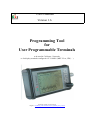
User Programmable Terminals
to be used in CANopen - Networks
or for display terminals configured via "CANdb" (MKT-View, CDP, .. )
Document Number: 85110 (English)
Original: C:\CBProj\UptWin1\DOKU\art85110_Manual_UPT_Tool.odt
Doc.-Nr. 85110
Table of contents
1. VERSION HISTORY.................................................................................................................... 4
2. PREFACE.......................................................................................................................................5
3. PURPOSE AND TERMINAL FEATURES................................................................................ 6
4. SYSTEM REQUIREMENTS........................................................................................................6
5. INSTALLATION........................................................................................................................... 7
6. FURTHER INFORMATION........................................................................................................7
7. DESCRIPTION OF THE PROGRAMMING TOOL................................................................ 9
7.1 THE MAIN WINDOW.........................................................................................................................9
7.2 MAIN MENU...................................................................................................................................10
7.3 STATUS BAR...................................................................................................................................10
7.4 THE ONLINE-HELP-SYSTEM............................................................................................................11
7.5 THE SIMPLE PAGE EDITOR..............................................................................................................12
7.6 LCD SIMULATOR WINDOW..............................................................................................................16
7.7 SYSTEM COMMAND INTERPRETER................................................................................................... 17
7.8 COMMUNICATION CHANNELS.......................................................................................................... 18
7.8.1 SDO channels........................................................................................................................19
7.8.2 PDO channels....................................................................................................................... 20
7.8.3 Communication channels for CANdb - signals.....................................................................23
7.9 APPLICATION VARIABLES................................................................................................................24
7.9.1 Variables on SDO channels.................................................................................................. 25
7.9.2 Variables on PDO channels.................................................................................................26
7.10 PAGE DEFINITIONS........................................................................................................................27
7.10.1 Page Definition Header...................................................................................................... 27
7.10.2 Definition of Display Lines................................................................................................. 28
7.10.3 Colours................................................................................................................................30
7.10.4 The Format String in display lines......................................................................................31
7.10.5 Using Display Lines as Menu Items....................................................................................33
7.10.6 Overlapping graphics..........................................................................................................34
7.11 DEFINITION OF SPECIAL DISPLAY COMMANDS.................................................................................34
7.12 DEFINING EVENTS – AN OVERVIEW............................................................................................... 35
7.13 THE EVENT DEFINITION TAB.......................................................................................................... 35
7.13.1 Defining Events – the definition language..........................................................................36
7.14 GLOBAL EVENTS.......................................................................................................................... 37
7.15 DISPLAY PAGE OVERVIEW............................................................................................................ 38
7.16 THE ICON PAGE............................................................................................................................ 39
7.16.1 Reserving memory for icons (and other special features).................................................. 40
7.17 GENERAL SETTINGS......................................................................................................................41
7.17.1 General UPT Options......................................................................................................... 42
7.18 THE TEXT ARRAY PAGE...............................................................................................................43
7.19 THE ERROR PAGE.........................................................................................................................43
© MKT / Doc.-Nr. 85110
Version 1.6
Page 2 / 69
Doc.-Nr. 85110
Table of contents
7.20 SCREEN SNAPSHOT VIA CAN........................................................................................................44
8. THE DISPLAY INTERPRETER............................................................................................... 45
8.1 GENERAL SYNTAX...........................................................................................................................45
8.1.1 Numeric Expressions.............................................................................................................45
8.2 STRING FUNCTIONS.........................................................................................................................53
8.3 INTERPRETER COMMANDS...............................................................................................................54
8.4 PROGRAM CONTROL COMMANDS......................................................................................................54
8.4.1 Goto, Call and Return...........................................................................................................54
8.5 THE ASSIGN-COMMAND...................................................................................................................55
8.6 GRAPHIC OUTPUT COMMANDS......................................................................................................... 56
8.6.1 The ICON-command (ic).......................................................................................................56
8.6.2 The LINE-command (li)........................................................................................................ 56
8.6.3 The PIXEL-command (pi)..................................................................................................... 56
8.6.4 The FRAME-command (fr)................................................................................................... 57
8.6.5 The FILL RECTANGLE-command (fi)................................................................................. 57
8.6.6 The Draw Mode-command (dm)........................................................................................... 58
8.7 OTHER INTERPRETER COMMANDS................................................................................................... 59
8.7.1 The “led”-Command.............................................................................................................59
8.7.2 The “out”-Command............................................................................................................ 60
8.7.3 Timer commands and functions............................................................................................ 61
9. CANOPEN OBJECTS................................................................................................................. 63
9.1 CANOPEN OBJECTS FOR DIGITAL I/O-MODULES.............................................................................63
9.2 CANOPEN OBJECTS FOR ANALOG I/O-MODULES.............................................................................65
9.3 CANOPEN OBJECTS INSIDE THE UPT...............................................................................................66
10. TRANSFERRING THE APPLICATION INTO THE PROGRAMMABLE DEVICE ......68
11. ERROR MESSAGES.................................................................................................................68
11.1 SDO ERROR CODES.......................................................................................................................68
© MKT / Doc.-Nr. 85110
Version 1.6
Page 3 / 69
Doc.-Nr. 85110
Programming tool for „User Programmable Terminal“ (UPT)
1. Version history
Version number
V0.1
Date
Author
03.Nov.1999 W.Büscher
V0.2
13.Dec.1999 W.Büscher
V0.3
V0.4
22.Mar.2000 W.Büscher
31.May 2000 W.Büscher
V0.5
07.June 2000 W.Büscher
V0.6
V0.7
19.July 2000 W.Büscher
20.Feb.2001 W.Büscher
V0.8
V0.9
V1.0
29.Mar.2001 W.Büscher
05.Sept.2001 W.Büscher
27.Feb.2002 W.Büscher
V1.1
2003-05-28
W.Büscher
V1.2
2007-04-23
W.Büscher
V1.3
2008-09-17
W. Büscher
V1.4
V1.5
V1.6
2011-06-08
2013-04-15
2014-06-18
W. Büscher
W. Büscher
W. Büscher
© MKT / Doc.-Nr. 85110
Version 1.6
Remarks, Modifications
Creation of this manual (english, very
„preliminary“ !!)
First external release (still preliminary).
Programming Tool: Version 1.0 „beta“.
Added a few new interpreter functions.
Added a lot of new interpreter functions +
text array + TX-PDOs + SYNC + „onboard“
digital I/O-Lines .
Now incompatible with „older“ software.
Programming Tool: Version 1.1 „beta“ (or
later) required.
First german translation of the manual now
available.
„General UPT Options“ implemented and
described here.
Added „Display Lines used as Menu Items“.
Key combination to enter UPT setup can now
be modified; how is described here..
( new functions under construction )
Added some interpreter functions for PDOs
Added some notes for users of the CANdbcontrolled display terminal (whatever its
name will be ;-)
Notes about "DriverLINX" removed. Didn't
work properly under WinXP anyway !
+ This document is totally outdated ... !
Switched from *.doc to *.odt (odt =
OpenDocumentText)
Added a few fragments for the new "MKTView II" (copied from the online help
system!), including the "simple page editor".
Added notes about the file transfer options
Copied a few chapters from the online help
Added 'CDP' (CAN Display Terminal)
to this document's front cover page
Page 4 / 69
Doc.-Nr. 85110
Programming tool for „User Programmable Terminal“ (UPT)
2. Preface
This manual describes a windows program that can be used to program a special terminal called
„user programmable terminal“.
There is a special variant of the programming tool called "Programming tool for CANdb display
terminals". Unfortunately there is no special manual available for this yet. If you are a user of the
CANdb controlled display terminal, please ignore the chapters "CANopen, SDO, PDO" and all
paragraphs with the note "UPT only".
The software and accompanying written materials (including instructions for use) are provided "as
is" without warranty of any kind. Further, MKT Systemtechnik does not warrant, guarantee, or
make any representations regarding the use, or the results of the use, of the software or written
materials in terms of correctness, accuracy, reliability, currentness, or otherwise. The entire risk as
to the results and performance of the software is assumed by Licensee and not by MKT
Systemtechnik or its distributors, agents or employees.
There are no other warranties, either expressed or implied, including but not limited to implied
warranties of merchantability and fitness for a particular purpose, with respect to the software, the
accompanying written materials, and any accompanying hardware.
Note: In constrast to the programming tool's online-help-system (HTML), this document is a bit
outdated ! New functions are initially described only in the HTML-files, and later -in due coursetransferred into this document, too.
© MKT / Doc.-Nr. 85110
Version 1.6
Page 5 / 69
Doc.-Nr. 85110
Programming tool for „User Programmable Terminal“ (UPT)
3. Purpose and Terminal Features
The main purpose of the user programmable terminal is to display parameter values in a CANopenNetwork.
The most important features of the terminal are:
UPT-515: graphic LCD with 128*64 pixel
UPT-167, MKT-View I: graphic LCD with 320*240 pixel
MKT-View II : TFT screen with touchpanel, 480*272 pixel
"UPT"-terminals communicate with other devices in a CANopen network
one or more SDO servers which may be used to communicate with other devices
one SDO client which is used for setup and program transfer
the terminal can „listen“ to PDO channels and transmit PDO telegrams
"MKT-Views" are parametrized using CANdb files (Database for CAN), no CANopen
values from „input channels“ are stored in variables
user program can evaluate or modify these variables
display screens are arranged as „user programmable display pages“
every display page can display up to <n> numerical parameters
every display page can have a set of flexible „event definitions“ and „reactions“
an event definition can be a simple „keyboard event“
an event definition can also be a comparation of numeric values
an event reaction can be a simple „switch command“ to an other display page
4. System requirements
The programming tool for the user programmable terminal is a windows application (W95/98, Win
XP), therefore you will need a PC with windows installed. We have never tested Windows ME nor
Windows 2000, but they may work as well.
Sorry, but a LINUX version of this tool is not available.
Furthermore you need:
a CAN interface for your PC
the newest CAN driver software which the manufacturer of the CAN interface must provide
the windows programming tool (software by MKT Systemtechnik)
© MKT / Doc.-Nr. 85110
Version 1.6
Page 6 / 69
Doc.-Nr. 85110
Programming tool for „User Programmable Terminal“ (UPT)
5. Installation
The programming tool will be delivered on CD-ROM, or can be downloaded from the MKT
website. To install ...
Ensure Windows (preferrably XP, not "Vista") is installed properly on your PC
Install a CAN-Interface and the required driver software (not a produkt of MKT!)
If you use a CAN-Interface from PEAK, you should install the newest CAN driver software
from PEAK, along with Peak's "large" CAN driver called "PEAK CAN Driver V2.x" and Peak's
tools like NetConfig etc. Further Info can only be provided by Peak.
If you use one of ESD’s CAN-Interfaces, install their NTCAN driver system which is supplied
with the CAN interface. Carefully read ESD‘s manual before installing the interface, because
you may seriously damage the PC/Laptop and/or the interface if you don’t follow the
installation procedure.
If you use a CAN interface by Kvaser AB, install Kvaser's CAN-API (CANLIB) from the CD
which should have been shipped together with the device, or install it from the Kvaser site.
After that, there should be a new item named 'Kvaser Hardware' in the windows system control.
Use it to configure and test your Kvaser CAN interface.
Set the font display scaling to 100% (somewhere in the windows system menu)...
For Users of a german windows-installation only:
Setzen sie die Zeichenanzeige auf „Normalgröße“ (dies ist die Defaulteinstellung):
in der Taskleiste: Start – Einstellungen – Systemsteuerung – Anzeige – Einstellungen Schriftgröße:
„kleine Schriftarten“ (100% = Normalgröße, 10-Punkt-Arial mit 96ppi)
If you don’t set the font display scaling to 100%, the dialog elements of the programming tool
will look very ugly !
Start „InstallUptToolX.exe“ or (depending on the target) "InstallCANdbTerminal.exe" from
CD-ROM or your download-folder, and follow the instructions of the UPT-Tool-Installer.
Note that, as of 2010, there were three different "terminal programming tools" available from
MKT Systemtechnik:
- InstallUptTool1.exe : Old programming tool, only for "UPT-515" (not for UPT-128) .
- InstallUptTool2.exe : Programming tool for display terminals with CANopen protocol, for
example UPT-128, UPT-320 (and many others) .
- InstallCANdbTerminal.exe : For all devices, which use "CANdb" rather than CANopen.
"CANdb" is the name of a file format (by Vector) which describes all signals in a CAN
network. It is widely used in the automotive sector, but not in the automation industry.
To remove this software from your computer, use the deinstaller (start programs-UptWin1„unwise.exe“)
You may find this manual as a printable file in a subdirectory „Doku“.
6. Further Information
... is available in the following documents. Some of them are contained in the installation archive of
the programming tool (folder "Doku"), or can be downloaded from the MKT website .
© MKT / Doc.-Nr. 85110
Version 1.6
Page 7 / 69
Doc.-Nr. 85110
•
•
•
•
•
•
•
Programming tool for „User Programmable Terminal“ (UPT)
Document Nr. 85110: Manual for the UPT programming tools
Document Nr. 85111: Additional info for terminal parametrised via "CANdb" (e.g. MKTView, MKT-View +, MKT-View II, and others(!) ).
Document Nr. 85113: Description of the CAN Logger(!) utility
Document Nr. 85115: Description of the 'System Menu' (inside the terminal)
Document Nr. 85116: Specification of download protocol (only for developers)
Document Nr. 85118: Description of the CAN-Snooper (CAN monitor in some terminals)
Document Nr. 85130: Introduction and first steps with the MKT-View II (coming soon..)
© MKT / Doc.-Nr. 85110
Version 1.6
Page 8 / 69
Doc.-Nr. 85110
Programming tool for „User Programmable Terminal“ (UPT)
7. Description of the programming tool
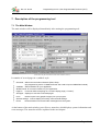
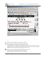
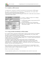
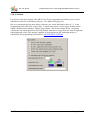
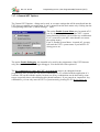
7.1 The Main Window
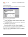
The main window will be displayed immediately after starting the programming tool.
(Note: There may be more functions in the latest software release !)
It contains of several pages in a „tabbed“ style:
Channels: define Communication Channels (PDO, SDO).
(the programming tool for "CANdb terminals" has a tab to import CANdb files instead)
Variables: define Variables for your application.
Global Events: for common reactions of your application.
Page #x:
All Pages: displays an overview of all used pages.
Icons:
General settings: used to display and modify some terminal settings.
Errors:
is used to define everything on a certaion display page (=”screen”).
used to import icons (graphic images) into your program.
shows all kinds of errors and other messages from the system.
At the bottom of the main window you will see a status bar, which displays system information and
error messages. The status bar will be explained in the next chapter.
© MKT / Doc.-Nr. 85110
Version 1.6
Page 9 / 69
Doc.-Nr. 85110
Programming tool for „User Programmable Terminal“ (UPT)
7.2 Main Menu
The main menu is used to
load programs from ASCII files (*.upt)
save programs as ASCII files
transfer programs to or from the terminal (via CAN)
open auxiliary windows for debugging etc („View“)
import or create new Icons for the UPT program
start the online help system
start and stop the system interpreter
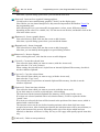
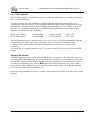
7.3 Status Bar
At the bottom of the main window you will see the status bar, which will display some information
about the current system state (e.g. „Transfer in progress“ and so on).
By clicking at the „Simulator“-button you may switch to the LCD-simulator window (if it’s not
already visible).
The second panel from the left (here: „Running“) shows a quick info about the current state of the
programming tool or the application program. Some possible labels are:
Running: Your application is running (i.e. it is being executed)
Stopped:
Your application has been stopped for any reason
Transfer: A program upload or download is in progress.
The right field in the status bar will display the last error message (if any) or other system messages.
In the example shown above the last system message was an indication that the CAN interface has
been successfully initialized.
You may switch to the error display page by double-clicking into the status message field.
For debugging purposes you may also send a command string to the system command interpreter by
typing it into the status message field.
© MKT / Doc.-Nr. 85110
Version 1.6
Page 10 / 69
Doc.-Nr. 85110
Programming tool for „User Programmable Terminal“ (UPT)
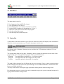
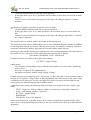
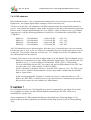
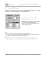
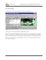
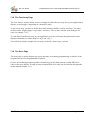
7.4 The Online-Help-System
You will always find the latest
information about the UPT
programming tool in the online help
system, which works like most other
windows applications.
The screenshot on the right shows an
example for the online-help-system.
If you are not familiar with this
system, you should consult a
Windows™ manual.
You may start the Online-Help-System by
clicking at the menu entry „Help“ in the main menu to get an overview of all topics in the help
file,
clicking at any „Help“-Button to get help on a particular dialog,
pressing F1 to get context-sensitive help on the dialog-element that has the input focus,
pressing F2 to get command-specific help about any command of the UPT’s commandinterpreter.
If you have problems because Windows™ cannot find the help file, you may enter the complete
path and file name for the help file in the „General Settings“-tab (see chapter 7.17 for details).
© MKT / Doc.-Nr. 85110
Version 1.6
Page 11 / 69
Doc.-Nr. 85110
Programming tool for „User Programmable Terminal“ (UPT)
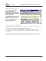
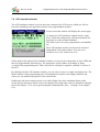
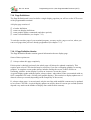
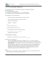
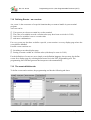
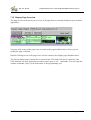
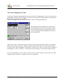
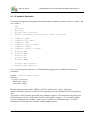
7.5 The Simple Page Editor
The "simple page editor" is an alternative, and possibly simpler, method to edit or create the graphic
user interface in your application. An application contains various display pages, which can be
modified on the tabsheets of the programming tool as shown below.
As already mentioned, a complete reference can be found in the online help system of the
programming tool.
© MKT / Doc.-Nr. 85110
Version 1.6
Page 12 / 69
Doc.-Nr. 85110
Programming tool for „User Programmable Terminal“ (UPT)
The toolbar of the "simple" page editor contains these buttons :
(Arrow or Pointer tool) : Move or modify items on the screen.
Hold the mouse pressed and move it, to change the position.
Use the CTRL-key, or pull a marker frame (start in an empty region on the screen) to select
multiple items at once. Single-click on an item to select it (for cut / copy / paste operations).
Double-click on an item to open a special property editor for it .
(Text tool) : Insert a simple alphanumeric TEXT line on the screen.
First select this tool (click at the symbol in the toolbar).
Single-click into the screen to place a new text item there.
© MKT / Doc.-Nr. 85110
Version 1.6
Page 13 / 69
Doc.-Nr. 85110
Programming tool for „User Programmable Terminal“ (UPT)
After that, a special dialog opens where you can edit the new item.
(Icon tool) : Insert an Icon (symbol; bitmap graphics).
Use this tool to insert small bitmap graphics ("Icons") on the display page.
Note: Before you can insert bitmaps here, they must be imported on the tabsheet "Icons" in
the programming tool.
After inserting an icon, you can modify its appearance (colour, zoom, different symbols
depending on the value of a variable, etc). Use the arrow tool for this, and double-click on the
icon in the editor screen.
(Button tool) : Insert a graphic button.
First select this tool, then click into the screen to add a button.
After that, a special dialog opens where you can edit the button.
(Bargraph tool) : Insert a bargraph.
First select this tool, then click into the screen to add a bargraph.
After that, you can modify the bargraph in a special dialog window.
(Button tool) : Insert a diagram.
After selecting this tool, click into the screen to add a diagram.
(Cut tool) : Cut out the selected item.
First select the item which you want to remove (with the Arrow tool),
then select the "Cut" tool (scissors).
When cutting, the selected item is copied into an internal clipboard-like memory, but this is
not the windows clipboard.
(Copy tool) : Copy the selected item.
First select the item which you want to copy (with the Arrow tool),
then select the "Copy" tool.
The selected item is copied into an internal clipboard-like memory, but this is not the
windows clipboard.
(Paste tool) : Paste item into selection.
First select the item which you want to overwrite (with the Arrow tool).
If you don't want to overwrite a selected item, select nothing.
The item stored in the internal clipboard-like memory will be pasted to the screen.
If an item was selected (marked with a red selection frame), it will be replaced with the
"pasted" item.
If no item was selected, the item will be inserted at the position of the insert cursor, which is
marked with a small red dot.
The insertion cursor can be set (before inserting an item) with a short click into a nonoccupied screen area. After inserting an element, the insertion cursor will be moved down (or
right, at the bottom of the screen), depending on the size of the object which has been
inserted, so that there will be no overlap. It's easy to fill a page with equally spaced items this
way.
(Undo tool) : Undo recent operation(s).
© MKT / Doc.-Nr. 85110
Version 1.6
Page 14 / 69
Doc.-Nr. 85110
Programming tool for „User Programmable Terminal“ (UPT)
Click this 'UNDO'-button to undo the recent operation.
In the page editor, up to 20 (?) operations can be undone, because they are saved in an undohistory.
Caution: If you exit from the current page in the editor, the changes cannot be "undone"
anymore !
(Redo tool) : Redo recent undo-operation(s) aka "un-undo".
Click the 'REDO'-button to undo the recent und-operation.
In the page editor, up to 20 (?) undo-operations can be undone, there is an extra buffer for
this.
Caution: If you exit from the current page in the editor, the changes can neither be "undone"
nor "redone" anymore !
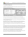
The selected object is marked with a red(?) frame in the drawing area.
The combo box in the editor's toolbar allows you to select individual display elements (in addition
to selecting them with the arrow tool). This may be necessary for example, if a display element is
completely obscured by another, and cannot be selected with the mouse directly.
Selecting an object in the drawing area (with the arrow tool) will automatically select that object in
the combo box, too. The entries in the combo box can be interpreted as follows :
[line number] ELEMENT-TYPE : element-text
Example (from the screenshot at the begin of this chapter) :
[9] TEXT : Supply Voltage
which means:
The currently selected display item is defined in line number 9 (an array-index; numbering
starts at zero);
the item is a simple TEXT (alphanumeric);
the display text begins with the string "Supply Voltage".
Graphic controls can be aligned to an 8 * 8 pixel grid. To show this grid, or let a coordinate snap to
the grid, select "Option"..."Page Editor" in the programming tool's main menu. If the option "Snap
coordinates to 8*8 pixel grid" is active, the upper left corner of an object will be aligned to the
nearest grid point when moving the object with the mouse.
At the time of this writing, the following display elements were supported by the "simple" page
editor:
•
•
•
•
•
TEXT : simple text, with or without variables (use asterisks as placeholder characters)
ICON : small bitmap graphics ("symbols")
BUTTON : graphic button
BARGRAPH
DIAGRAM : Y(t) or X/Y diagram
Other 'special' functions, or graphic items, can be created or modified as explained in the online
help system of the programming tool (which, by the way, will always be more up-to-date than this
document).
© MKT / Doc.-Nr. 85110
Version 1.6
Page 15 / 69
Doc.-Nr. 85110
Programming tool for „User Programmable Terminal“ (UPT)
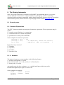
7.6 LCD simulator window
The LCD simulator window is used to show the contents of the LCD screen, which you will see
later after uploading your application into the user programmable terminal.
In most cases this window will display the current page.
As long as the LCD simulator window has the „input
focus“ (blue title background), all keyboard inputs will
be passed on to the terminal simulator.
This allows you to test your programmed event handlers
etc.
The LCD simulator window can be moved and sized
independent of the main window. You may even
maximize it to a real „full screen view“.
On the panel at the bottom of the simulator window you can see the current state of some LEDs and
the user-programmable function keys. The appearance of this window will change in future
versions of the programming tool. There may also be a display for optional „onboard“ I/O-lines of
the UPT.
By clicking into the LCD simulator window, you can select (or move) a single text display line. The
MAIN window of the programming tool will automatically switch to the display definition tab
where you can modify all properties of the selected line.
Holding the left mouse button pressed on a visible display line in the simulated display while
slowly moving the mouse allows to move the display line aroud (only works for normal text display
lines from chapter 7.10.2, not for general graphic commands like „line“, „rectangle“ from chapter
8.6).
© MKT / Doc.-Nr. 85110
Version 1.6
Page 16 / 69
Doc.-Nr. 85110
Programming tool for „User Programmable Terminal“ (UPT)
7.7 System Command Interpreter
The system command interpreter is a part of the UPT firmware, but almost the same code is also
implemented in the programming tool. Most of your „user program“ is executed by the system
command interpreter. The system command interpreter is used to evaluate formulas, event
definitions and to execute complex graphic commands (they all will be explained later). A
description of some commands can be found in the appendix.
You may enter a system command in the status line, where usually error messages and warnings are
displayed. This feature is only intended for experienced users and for debugging purposes.
Some of the commands that you can enter are directed to the display list interpreter and may result
in „strange“ behaviour of the program (see help system for detailed info).
All commands that cannot be processed by the programming tool will be directed to the terminal’s
interpreter. The format of these commands will be equivalent to the syntax of event-reactions.
© MKT / Doc.-Nr. 85110
Version 1.6
Page 17 / 69
Doc.-Nr. 85110
Programming tool for „User Programmable Terminal“ (UPT)
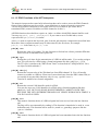
7.8 Communication Channels
This page is used to define the communication channels which the terminal uses to exchange data
with other devices on the CANopen network.
There are different types of communication channels:
SDO channel (Service Data Object)
a „slow“device-to-device connection which allows to exchange data from a device’s object
dictionary.
PDO channel (Process Data Object)
a „fast“ communication channel that is used to transfer process data with a high priority, for
example digital inputs, analogue values from sensors etc.
CANdb-Messages (only for a few special variants)
Quite similar as a CANopen-RPDO, but any CAN-identifier can be used. CANdb-signals and
-messages are defined in a CAN-database file. Up to 64 signals can be contained in a message.
Channel number "30" identifies a variable which is connected to a CANdb-signal.
Note that the terminal can only „listen“ to PDO channels. It can not request the transmission of a
PDO from another device via RTR (because this may cause a lot of trouble ...)
You have to define at least one communication channel for every device that the terminal shall
communicate with. The channels will later be used to transfer values from other devices into the
variables of your terminal program.
© MKT / Doc.-Nr. 85110
Version 1.6
Page 18 / 69
Doc.-Nr. 85110
Programming tool for „User Programmable Terminal“ (UPT)
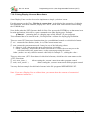
7.8.1 SDO channels
SDO channels provide a „slow“device-to-device connection which allows to exchange data from a
device’s object dictionary.
You have to define the CAN-identifiers of all SDO-channels which the terminal shall use to
communicate with other devices. You will find the Identifier values in the description of the device
that transmits a particular SDO or in the CANopen Draft Standard 301 (CiA „DS301“). Most I/Odevices use a „pre-defined connection set“ with the following definitions for the SDO’s CANIdentifier (which DS301 calls „COB-IDs“).
SDO(server->client) :
SDO(client->server) :
CAN-Identifier
CAN-Identifier
= (1408+node-ID)
= (1536+node-ID)
= 1409...1535
= 1537..1663
All CAN-Identifiers here are decimal values. The „client->server“-ID will be transmitted from the
client (which is the UPT) to the server (which may be an I/O-module) to initiate a transfer
(„request“). The „server->client“-ID will be transmitted back from the server to the client
(„answer“).
The „node ID“ is a number between 1 and 127, on many simple I/O-devices it can be set via DIPswitch.
Always be aware:
An SDO connection is just a „point-to-point“ link between two partners. You must take extra care
to use only SDO connections that are not yet occupied by other devices. If a simple I/O-device only
has one SDO channel and this SDO is already occupied by an other device (maybe a PLC, SPS, a
servo drive or something else), you can not connect the UPT to this device via „active“ SDO
request because this would cause severe collisions on the network (same CAN-ID transmitted by
several devices, SDO protocol violations etc.).
In the User Programmable Terminal, a variable can be connected via SDO to an other device in the
network.
© MKT / Doc.-Nr. 85110
Version 1.6
Page 19 / 69
Doc.-Nr. 85110
Programming tool for „User Programmable Terminal“ (UPT)
7.8.2 PDO channels
PDO channels provide a „fast“ communication channel that is used to transfer process data with
high priority, for example digital inputs, analogue values from sensors etc.
You have to define the CAN-identifiers of all PDO-channels which the terminal shall transmit or
receive. You will find the Identifier values in the description of the device that transmits a particular
PDO or in the CANopen Draft Standard 301 (CiA „DS301“). Most I/O-devices use a „pre-defined
connection set“ with the following definitions for the PDO’s CAN-Identifier (which DS301 calls
„COB-IDs“).
PDO1(tx) :
PDO1(rx) :
PDO2(tx) :
PDO2(rx) :
CAN-Identifier
CAN-Identifier
CAN-Identifier
CAN-Identifier
= (384+node-ID)
= (512+node-ID)
= (640+node-ID)
= (768+node-ID)
= 385...511
= 513...639
= 641...767
= 769...895
All CAN-Identifiers here are decimal values. Note that „tx/rx“ in this table has to be seen from the
I/O-devices point of view, so the „tx“ PDO’s are transmitted by an I/O-module and can be received
by the UPT. The possible values for node-IDs are 1..127. Simple devices like I/O-Modules often
use a DIP-switch to set the node-ID.
Example: You want to receive the state of digital inputs of an I/O-Module. The I/O-Module uses its
PDO1(tx) to transmit process data, which contain the digital inputs. The node-ID of the I/OModule is set to „1“, so the resulting CAN-Identifier will be (384+1)=385(decimal).
To receive this PDO with the UPT, you want to use the first PDO-channel of the UPT. Just
enter the value „385“ in the column „CAN-ID of PDO“.
Set the „Direction“-Column to „Receive“ (from the UPT’s point of view). The UPT is now
able to receive a PDO with this identifier, and you may define variables that use the PDO
data as „input values“.
In the User Programmable Terminal, a variable can (now) be connected either to a „TX“PDO or an „RX“-PDO. A variable can never be connected to two channels at the same time.
But you may connect several variables to a PDO-channel.
Caution !
In a CANopen-network, one CAN-Identifier may only be transmitted by one single device in the
net. So you have to make sure that all PDO channels transmitted by the UPT will never be
transmitted by „anyone else“.
Some components of a PDO channel definition are described in the following chapters. For a
detailed (and up-to-date) explanation you should read the Help-System of the UPT Programming
Tool.
© MKT / Doc.-Nr. 85110
Version 1.6
Page 20 / 69
Doc.-Nr. 85110
Programming tool for „User Programmable Terminal“ (UPT)
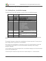
7.8.2.1 PDO Transmission Direction
Since April 2000, the UPT515 supports Reception and Transmission of PDOs.
Therefore you have to specify, if a PDO channel shall receive(1), transmit(2) or be passive(0).
Note: „Transmit“ and „Receive“ has to be seen from the UPT’s point of view.
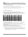
7.8.2.2 PDO Transmission Type
Since April 2000, the UPT515 supports different types of PDO transmission.
The PDO transmission type is defined by a numerical value. It is taken from CiA DS301.
You may find more information on this in CiA Draft Standard 301, Version 4.0 (16.6.1999), Page
9-83 in the description of Objects 1400h-15FFh (PDO Communication Parameter), Table 54,
„Description of transmission type“:
Transmission
Cyclic Acyclic
Type
0
X
1-240
X
241-251 reserved
252
253
254
255
Synchronous Asynchronous RTR only
X
X
X
X
X
X
X
X
A transmission type of zero means that the message shall be transmitted synchronously with the
SYNC object but not periodically (??..).
A value between 1 and 240 means that the PDO is transferred synchronously and cyclically, the
transmission type indicating the number of SYNC which are necessary to trigger PDO
transmissions/receptions.
The transmission types 252 and 253 mean that the PDO is only transmitted on remote transmission
request. The UPT515 treats both 252 and 253 exactly the same way.
Transmission type 254 is „manufacturer specific“ (which is not defined yet).
Transmission type 255 is „defined in the decive profile“ (which does not exist here).
Note: By the time of this writing, the UPT515 did not support all of the transmission types shown
above. The Simulator inside the UPT Programming Tool does not support any „real time“
PDO-Transfer at all, because the CAN-Controller used in the PC’s CAN-Interface is not
compatible to the Controller in the „real“ UPTs.
© MKT / Doc.-Nr. 85110
Version 1.6
Page 21 / 69
Doc.-Nr. 85110
Programming tool for „User Programmable Terminal“ (UPT)
7.8.2.3 PDO-Definition-„Flags“
These „Flags“ have been implemented for „very special PDOs“. You can see them on the
Communication Channel Definition screen on page 18.
Only the last PDO channel can be configured to be a „System State PDO“ by setting the FLAG
value to „1“ (? see Online-Help-System ?).
The „System State PDO“ has the following contents:
Byte[0] = UPT run mode („Status“??) ... please ignore this byte !!
Byte[1] = digital Inputs of the UPT
Byte[2] = current display page of the UPT
Byte[3] = Key-Matrix[0], the „first“ 8 keys of the keyboard driver.
Byte[4] = Key-Matrix[1], the „next“ 8 keys of the keyboard driver.
You should leave all flags „zero“ to use flexible TX-PDO-Mapping from Variables.
© MKT / Doc.-Nr. 85110
Version 1.6
Page 22 / 69
Doc.-Nr. 85110
Programming tool for „User Programmable Terminal“ (UPT)
7.8.3 Communication channels for CANdb - signals
(Not for CANopen, but exclusively for the "mobile bus" used in the automotive area)
Channel number 30 is reserved as a "dummy" for all UPT-variables connected to a CANdbcompatible signal.
CANdb means "database for CAN". In a CAN database file (extension *.DBC) so-called messages
and signals are defined (and some other objects which are ignored here).
The programming tool has the possibility to import DBC-files and convert some of the information
contained in a DBC file into the definition of an UPT-variable.
Detailed information on how to achieve this can only be found in the online help system of the
programming tool. Switch to the tab sheet "CANdb" and hit the Help-button on that page.
© MKT / Doc.-Nr. 85110
Version 1.6
Page 23 / 69
Doc.-Nr. 85110
Programming tool for „User Programmable Terminal“ (UPT)
7.9 Application Variables
This page is used to define all variables which the terminal will use to show and modify parameters.
Variable properties are:
Name
Channel
PDO/SDO – definition
Update – Time
Data Type
Access Rights
Flags
Default Value
Minimum Value
Maximum Value
Factor, Divisor, Offset
Most of your variables will be connected to a communication channel, but they can also be used as
internal variables which keep temporary values etc.
The Channel-Number also defines the TYPE of a communication channel:
Channel 0..9 is used for SDO-Client-channels (or „future Reserve“),
Channel 10..19 is used for PDO-channels (also with „Reserve“),
Channel 20.29 will be used for a special serial communication link in future,
Channel 30 is used for signals defined in a CANdb file,
Channel 255 means „this variable is not connected to any communication channel“.
The other columns of a variable-definition will be explained later.
© MKT / Doc.-Nr. 85110
Version 1.6
Page 24 / 69
Doc.-Nr. 85110
Programming tool for „User Programmable Terminal“ (UPT)
7.9.1 Variables on SDO channels
A variable can be „connected“ to an object in an other device in the network via SDO channel.
The „objects“ of a CANopen-device are located in a so-called dictionary. Every object of this
dictionary is defined by its Object-Index and Subindex .
These parameters are defined on the following panel, which will be visible if the current variable is
connected to an SDO-channel:
To „connect“ a variable to an object of a CANopendevice, you have to define:
the SDO channel number (which connects the UPT
to a certain device)
the index and subindex of the CANopenobject
data type, access rights, min/max-values, scaling etc
like any other variable
7.9.1.1 Usage of Index and Subindex for SDO variables
For a variable which is connected to an SDO channel, you have to define an index and a subindex.
The „objects“ of a CANopen-device are located in a so-called dictionary. Every object of this
dictionary is defined by its Object-Index and Subindex.
The Object-Index is a 16-bit-number which is usually defined in hexadecimal format. Hexadecimal
Numbers always have to be entered beginning with the „0x“ or „$“-prefix, otherwise the interpreter
would treat them as decimal numbers.
The Subindex is an 8-bit-number which is often used for arrays or structured objects.
For example, a DS401-type module with 5 digital inputs may have an Object 0x6020 which
contains the state of the digital inputs. Subindex 0 of this object will have the content „5“ to
indicate that there are 5 digital inputs, subindex 1 will hold the actual state of the first digital input,
subindex 2 the state of the second input and so on.
Index and Subindex of CANopen-Objects are often defined in a device’s manual. But for many
objects you may also find the required information in a so-called Device Profile . There are device
profiles for different types of CANopen-devices, for example:
DS401: Device Profile for I/O Modules
You may obtain these profiles at CiA ( Can in Automation, www.can-cia.de ) if you need.
© MKT / Doc.-Nr. 85110
Version 1.6
Page 25 / 69
Doc.-Nr. 85110
Programming tool for „User Programmable Terminal“ (UPT)
7.9.2 Variables on PDO channels
The input of a variable can be connected to a part of a PDO channel (a PDO can carry up to 8 bytes
of information, and you will usually only use a part of that data field).
To „connect“ a variable to a PDO channel, you have to
define these parameters on a special dialog panel:
the „UPT-internal“ number of the PDO channel
the number of data bits that shall be transferred
from the PDO into the variable
the number of the fist data bit in the PDO (which is
the least significant bit, starting with bit 0 )
data type, access rights, min/max-values, scaling
etc like any other variable
Notes:
only 1-bit-parameters can be read from any bit-position in the PDO.
8-, 16-, 24- or 32-bit-Parameters must start on a BYTE boundary in the PDO data field, so the
„number of the first bit in the PDO“ must be a multiple of 8.
Parameters with more than 8 databits are always transferred in „low to high-byte-order“.
If the Programmiertool detects obvious Errors, for example conflicting data types and value
ranges, it will mark some of the edit-fields with red color and issue a warning message.
© MKT / Doc.-Nr. 85110
Version 1.6
Page 26 / 69
Doc.-Nr. 85110
Programming tool for „User Programmable Terminal“ (UPT)
7.10 Page Definitions
The Page Definition tab is used to define a single display page that you will see on the LCD screen
of the programmable terminal.
A display page consists of
a header definition
some text-display-definitions
some graphic display commands (and other specials)
some event-definitions (see chapter 7.12)
To switch to an other page of your terminal program, you may use the page overview, where you
can see all pages that you have already programmed (see chapter 7.15).
7.10.1 Page Definition Header
The Page Definition Header contains general information about a display page.
Some of these options are:
Always redraw this page completely
If this option is checked (activated), the whole page will always be updated completely. This
requires quite a lot of CPU time but may be necessary if you use overlapping graphics or moving
graphics. A complete screen update always includes erasing the screen, so there will be no
remaining „rubbish“ on the display if you let an icon move across the screen.
A typical display-update with the option „always redraw“ takes about 250ms (on terminals with an
8051-compatible CPU and a 128*64-pixel graphic display). This results in a display update-rate of
about 4 screens per second (depending on the complexity of the screen).
If „always redraw page“ is not activated, only the text lines with modified contents may be updated
to save some CPU time. A typical display update-rate will be about 10 screens per seconds (but this
depends very much on the number of display-lines with flexible contents).
© MKT / Doc.-Nr. 85110
Version 1.6
Page 27 / 69
Doc.-Nr. 85110
Programming tool for „User Programmable Terminal“ (UPT)
7.10.2 Definition of Display Lines
To define lines of text that you want to display on the terminal’s LCD screen, you may use the tab
display lines on the page definition sheet.
The table on the left shows all currently defined display lines on the current display page.
The „property“-panel on the right shows more detailed information about one single display line.
You may edit the properties of a display line in the table or on the property panel, the information
will always be updated on both parts.
If the simulated LCD screen is visible, you will immediately see the effects of the changes to a
display line. For example, if you change the Y-Position of a display string via up/down-scroller in
the display line property panel, you will the text moving on the simulated LCD screen.
The currently edited display line can be marked in the LCD simulator window with a thin dotted
frame.
If some graphic elements or text lines on the screen overlap, you should be aware of their drawing
order (see chapter 7.10.6). The order of the definition lines can be modified with the mouse. Hold
the left button pressed while moving the mouse in the column "Nr" up or down. A black horizontal
bar shows the location where the moved entry will be inserted when the mouse button is released.
This row-moving procedure is also possible in some other tables of the programming tool.
The button „Insert“ is used to insert a display-line (at the current position in the grid).
The button „Delete“ removes the display line which is currently marked in the grid.
Some „special“ functions for editing display lines may be found by clicking into the grid with the
right mouse-button. A popup-menu will open and show you all possible options.
© MKT / Doc.-Nr. 85110
Version 1.6
Page 28 / 69
Doc.-Nr. 85110
© MKT / Doc.-Nr. 85110
Programming tool for „User Programmable Terminal“ (UPT)
Version 1.6
Page 29 / 69
Doc.-Nr. 85110
Programming tool for „User Programmable Terminal“ (UPT)
7.10.3 Colours
For devices with colour display (like MKT-View II) the programming tool allows you to select
individual colours for each display element ( Text, Button, Bargraph, etc).
But we recommend, that for most display elements, you set the individual colour to "-1" in the
programming tool's edit field. Colour value -1 (minus one) means "use the page's default colour",
which is defined on the tabsheet "Display Page Header" like in the example below. Assigning
colours this way means that most (if not all) display elements on a page share the same foregroundand background colour. This greatly simplifies to switch between day- and night-design as
explained in the programming tool's built-in ONLINE HELP SYSTEM .
© MKT / Doc.-Nr. 85110
Version 1.6
Page 30 / 69
Doc.-Nr. 85110
Programming tool for „User Programmable Terminal“ (UPT)
7.10.4 The Format String in display lines
A „format string“ is one of the display line properties of a display line definition.
The format string can...
be a simple constant text string
contain special „place holders“ like „****“ for numeric digits
be used to show icons (in backslash sequences like „\iMyIcon“ )
Special characters in a format string are:
*
will be replaced by a numerical digit or a string expression
will be replaced with the sign of a numeric value (+,-)
\\
displays a single backslash
\displays a "-"-character
\cN
sets the text-color to (N)
\CN
sets the background-color to (N)
\mN
switches the draw mode for all following letters
\i<Icon-Name>[,<Invert-Flag>]
Inserts an Icon (see below)
Some format string - examples:
Voltage= *****.** V
Icons: \iF_ok,kd0 \iF_no \iF_stop
DrawModes: \m0 Normal \m5 Invers \m8 Blink
Inserting Icons in a display line:
See the second example. Here three icons (named „F_ok“, „F_no“ and „F_stop“) are
inserted in a single display line. Each icon will be treated as a „letter“ when shown on the
screen. That means, if you change the X,Y-position of the display line you will also move all
icons of that line.
You may also use an optional „state“-expression to invert the icon’s color depending on a
numerical argument (after the icon’s name, separated by comma). This feature has been
implemented to simplify graphic „function keys“ just above the Keys F1..F4. In the
example, the Icon „F_ok“ will be inverted as soon as the first function key is pressed
(because the expression „kd0“ is TRUE while F1 is pressed).
Notes:
If the Icon in a „\i<Icon-Name>“-sequence is unknown (because it is not defined on the Icon
Page), the sequence will be displayed as normal text.
© MKT / Doc.-Nr. 85110
Version 1.6
Page 31 / 69
Doc.-Nr. 85110
Programming tool for „User Programmable Terminal“ (UPT)
You should activate the option „always redraw this page completely“ in the page definition
header, if you use „invertable“ icons in a display line. Reason: The interpreter may not notice
that the state of the <Invert-Flag> has changed because the Invert-Flags are evaluated only if a
display line is „redrawn“.
You should activate the option „always redraw this page completely“ in the page definition
header, if you use the „\m<Draw-Mode>“-sequence in a format string and <DrawMode> is a
variable expression. Reason: Same as above.
If you want to „separate“ multiple Icons in a single display line, use the space character. The
width of the spaces depends on the standard font used for this display line. Use the „4*6-pixelfont“ for a „good resolution“.
If you just want to draw a single Icon with variable coordinates, use the icon-command instead
of a backslash-sequence in a format-string.
© MKT / Doc.-Nr. 85110
Version 1.6
Page 32 / 69
Doc.-Nr. 85110
Programming tool for „User Programmable Terminal“ (UPT)
7.10.5 Using Display Lines as Menu Items
Some Display Lines can also be used to implement a simple „selection“ menu.
For this purpose, set the Flag „This line is a menu item“ in the display line properties of a display
line definition. This turns a normal „display line“ into a „menu item“ which can be seleced using
the CURSOR keys.
Next, define what the UPT firmware shall do if the User presses the ENTER key on that menu item.
In most applications, this will be a goto-command to an other display page. Example:
g"Menu2" (assuming there is a display page called „Menu2“ in your program)
This command has to be entered in the „Var/Expression“ column of a display page definition.
There are some UPT interpreter functions that give you additional control over this kind of menu:
mi : returns the line number (index, 0..n) of the current menu item.
mm: returns the current menu mode. It may be one of the following values:
0 = Menu is „Off“, that means the menu selection bar is invisible
1 = Mode „Selecting“, that means the menu selection bar is visible, the user may move the
selection between all „menu items“ on the current page using the cursor.
Other „modes“ are only valid for numeric edit field, for example 2 = „editing the value“.
There are also some „SET“-Procedures for this kind of menus, which have the same names as the
„GET“-Functions:
mi( <new_item> )
allows setting the „current“ menu item under program control
mm( <new_mode> )
allows setting the „current“ menu mode under program control
You may find an example for this kind of menus in the file \programs\NEWMENUS.UPT .
Note: If you use a Display Line as a Menu Item, you cannot show the contents of a numerical
parameter in that line !
© MKT / Doc.-Nr. 85110
Version 1.6
Page 33 / 69
Doc.-Nr. 85110
Programming tool for „User Programmable Terminal“ (UPT)
7.10.6 Overlapping graphics
For some special effects you may place some visible elements (text or graphics) in front of other
visible elements.
For example, there may be a large icon in the background and a little text display line in front of the
icon.
To achive this effect, the icon must be drawn first and the text must be drawn afterwards. The
sequence (or „drawing order“) is defined by the row number in the screen definition tables.
Any element with the row number „0“ will be drawn first, the element number „1“ will be drawn
second and so on.
When using overlapping graphics, you should always activate the option „redraw page completely“
in the page definition header.
7.11 Definition of special display commands
The following „special“ display commands are used to display graphic elements on the LCD.
icon (ic)
line (li)
pixel (pi)
frame(fr)
fill_rect(fi)
draws a small image („icon“)
draws a line
sets a single pixel
draws a rectangular frame
draws a solid rectangular shape
To set some additional parameters that affect the graphic drawing commands, you may use the
following commands:
draw mode(dm)
sets the draw mode
These commands may be entered in an abbreviated form into one command line. A more detailed
description of all system interpreter commands can be found in chapter 8.6.
If some graphic elements or text lines on the screen overlap, you should be aware of their drawing
order (see chapter 7.10.6).
You will find a detailed (and up-to-date) description of all interpreter-commands only in the online
help system of the programming tool.
© MKT / Doc.-Nr. 85110
Version 1.6
Page 34 / 69
Doc.-Nr. 85110
Programming tool for „User Programmable Terminal“ (UPT)
7.12 Defining Events – an overview
An „event“ is the occurrence of a special situation that you want to handle in your terminal
program.
An event can be:
User presses or releases a certain key on the terminal
The value of a variable exceeds a certain value (may have been received via CAN)
One bit of a variables is set to a certain value
and more combinations..
For every event you also have to define a special „event reaction“ on every display page where the
event shall be handled.
Possible event reactions are:
Switching to an other display page
Setting a certain variable to a certain value (which may be sent via CAN)
For the definition of events we use a simple event definition language, but you may also define
events for a display page by selecting them from a list in the UPT programming tool. The
programming tool will then generate the interpreter code automatically.
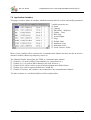
7.13 The event definition tab
To define events and reactions, the programming tool has the following tab sheet:
© MKT / Doc.-Nr. 85110
Version 1.6
Page 35 / 69
Doc.-Nr. 85110
Programming tool for „User Programmable Terminal“ (UPT)
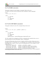
In this example there are only a few keyboard event definitions.
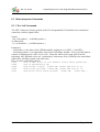
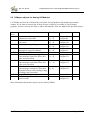
7.13.1 Defining Events – the definition language
To define events in your UPT application, you may use this event-definition-language.
Event-Type Parameter
(if required)
kd
key-name
ku
key-name
kb
key-name
kh
kc
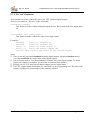
Description
cb
ce
cw
ch
co
ct
CAN-Error: Bus Off
CAN-Error (severe)
CAN-Warning
CAN-hardware fault
CAN-Error: Overflow
CAN-Error on transmit
t0 ... t3
User-timer
User-timerTimerCommands ( nr. 0...3) has
run off
pe
Current page has just been entered (Page
Enter)
Current page will soon be left (Page Quit)
pq
user has pressed a key
user has released a key
buffered keystroke
any key has been hit (system key)
reads and removes system key from buffer
(Note: There will certainly be more event-functions. Check the Help System of the programming
tool !)
The terminal’s interpreter evaluates the event definition as a boolean expression. You may also use
more complex numeric expressions as event definitions.
If the result of an event-definition (or expression) is non-zero, the system interpreter executes the
corresponding reaction method. An event reaction method is (internally) coded a string of
interpreter commands.
A more detailed and up-to-date description of the event-definition language can be found in the help
system of the programming tool.
A short description of numerical expressions can be found in chapter 8.1.1 of this document.
© MKT / Doc.-Nr. 85110
Version 1.6
Page 36 / 69
Doc.-Nr. 85110
Programming tool for „User Programmable Terminal“ (UPT)
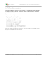
7.14 Global Events
You may define global events for situations that are independent of the current display. For
example, you may wish to „call“ a certain display page whenever there is a severe error on the
CAN-Bus. This can be achieved by the following example:
Event-Def.: ce (which means: "if there is a Can Error"...)
Reaction:
c"CanError"
(.. call the page "CanError")
Define this Event and it’s reaction method on the „Global Event“ page, so you don’t have to define
it on every used page (remember, the number of lines on a page is limited !).
There are some rules for global events that you should use:
Use global events for all events that would otherwise be equal on every page definition.
Don’t use display output commands in the reaction methods of global events, because this might
„interfere“ with the screen output of some of your pages.
If you defined a certain event as a global event (like „ce“ in the example above), you should not
define this event again as a „local“ event on any display page. However, defining an event twice
does not hurt the event handler. If multiple event definitions are TRUE at the same time, all
their correspondig reaction methods are executed.
© MKT / Doc.-Nr. 85110
Version 1.6
Page 37 / 69
Doc.-Nr. 85110
Programming tool for „User Programmable Terminal“ (UPT)
7.15 Display Page Overview
The Page Overview tab shows an overview of all pages that are currently defined in your terminal
application.
You may click on any of the page icons to switch to the page definition sheet, where you can
modify the page’s contents.
Double-Clicking on one of the pages here will also switch to the display-page-definition sheet.
The current display-page is marked by a colored frame. This mark will also be switched, if the
UPT-simulator lets your application run and executes goto or call – commands. You may stop this
with the command „Stop!“ in the main menu of the programming tool.
© MKT / Doc.-Nr. 85110
Version 1.6
Page 38 / 69
Doc.-Nr. 85110
Programming tool for „User Programmable Terminal“ (UPT)
7.16 The Icon page
The Icon Page is used to import and browse icons for your application.
You may import icons from monochrome windows bitmap files.
If the device supports color bitmaps (like „UPT167 Color“), you can also import color bitmaps. In
this case, you must use the ‚Import color bitmap‘ function from the main menu, not the ‚Import‘
button on the icon page. Take a look into the help system for details on color bitmaps in the UPT.
Before you can load icons into your application, you must reserve memory for the icons. This is
done with a special dialog.
© MKT / Doc.-Nr. 85110
Version 1.6
Page 39 / 69
Doc.-Nr. 85110
Programming tool for „User Programmable Terminal“ (UPT)
7.16.1 Reserving memory for icons (and other special features)
Icons and page definitions share the same memory inside the user programmable terminal.
Therefore you have to sacrifice some pages if you want to use icons in your application.
If you reduce the number of pages in your application, there will be more memory for icons.
As an example, if the terminal has enough memory for 50 display pages but you decide to use only
40, there will be about (50-40) * 1600 Bytes that you can use for icons.
Since April 2000, a part of the memory can also be used to store a „text array“ (see chapter 7.18).
Click on the „Icon Memory“ – button (on the icon page) to start this dialog for reserving icon
memory.
Since the introduction of the „Text Array“, the size of FLASH-memory for icons also depends on
the number of text-array-lines („text messages“).
Note: The „size of icon memory“ displayed in the dialog box is the available FLASH-memory that
could be used for icons. If you have problems with a display-page with many different icons,
the possible reason is a shortage of RAM-memory inside the „real“ UPT (The programming
tool does not know how much RAM will be available in the „real“ UPT when a particular
display page is visible). At the present time, the UPT’s firmware cannot „unload“ Icons
from its RAM if there is too few RAM to load more icons from ROM !
© MKT / Doc.-Nr. 85110
Version 1.6
Page 40 / 69
Doc.-Nr. 85110
Programming tool for „User Programmable Terminal“ (UPT)
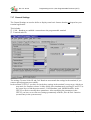
7.17 General Settings
The General Settings are used to define or display some basic features that do not depend on your
terminal application.
This includes
CAN – Baudrate to establish a connection to the programmable terminal
Terminal node ID
The settings Terminal Node ID and CAN-Baudrate must match the settings in the terminal, if you
want to upload programs successfully.
In the terminal „UPT515“ you have to check these settings in the terminal’s setup-menu, which you
may enter (for firmware-release 29-May-2000) after simultaneously pressing F2 and F3. Use
the cursor keys to find the menu-entries „CAN-Baudrate“ and „Modul/NodeID“ in the
UPT515 to check or modify these parameters. After modifying the parameters in the
UPT515 you have to save the new settings permanently with the „Save & Exit“-function
(second entry in the system menu) !
© MKT / Doc.-Nr. 85110
Version 1.6
Page 41 / 69
Doc.-Nr. 85110
Programming tool for „User Programmable Terminal“ (UPT)
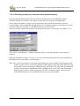
7.17.1 General UPT Options
The General UPT Options – dialog can be used to set some settings that will be transferred into the
UPT when you upload your application. It can be started from the main menu or by clicking into the
corresponding field in the „General Settings“ – table.
The option Enable System Menu may be turned off if
you are shure that you do not need the UPT’s system
menu functions (because you need the key-combination
F2+F3 yourself or you don’t want that the user enters
the system menu).
Even if „Enable System Menu“ is turned off, you may
still enter the UPT’s system menu if you hold F2+F3
during power-on.
The option Enable Debugging was intended to be used by the programmer of the UPT firmware
only (because he didn’t have a target debugger). You should leave this option off.
The key combination to enter the UPT’s system menu can now be changed from the
programming tool, because the old (fixed) combination F2+F3 collided with the application of a
customer. Be careful with this option, because not all key combinations can be detected by some
targets (especially those with multiplexed keyboard hardware). If you entered an ‚impossible‘ key
combination, you can only enter the UPT’s system menu by pressing F2+F3 during power-on.
© MKT / Doc.-Nr. 85110
Version 1.6
Page 42 / 69
Doc.-Nr. 85110
Programming tool for „User Programmable Terminal“ (UPT)
7.18 The Text Array Page
The Text Array is used to define an array of single text lines that you may use in your application to
display „text messages“ depending on a numerical value.
To use a text array, you have to define how much memory shall be used for text lines. You must
sacrifice some „display pages“ to get more „text lines“. This is done with the same dialog as for
icons, see chapter 7.16.1.
To read lines from the text-array in your application, you may call some string functions in text
display commands (see online help on „sa[]“ and „sr[]“ ).
You will find a simple example for text arrays in the file „demo1.upt“ (or later).
7.19 The Error Page
The error page is used to display any errory that may occur during programming or transfer of the
program into the User Programmable Terminal.
If errors occurr during program upload or download, you may find some hex-coded SDO error
codes in the error display. A table of most common SDO error codes can be found in the appendix
of this manual (chapter 11.1) .
© MKT / Doc.-Nr. 85110
Version 1.6
Page 43 / 69
Doc.-Nr. 85110
Programming tool for „User Programmable Terminal“ (UPT)
7.20 Screen Snapshot via CAN
To generate a printed documentation for the user of your UPT application, you may include „screen
photographs“ of the terminal’s displays. You don’t need a camera for that purpose, it is possible to
take a screen „snapshot“ via CAN-Bus.
Start the „Snapshot“ dialog from the „Transfer“ menu of the programming tool.
The parameters on the right side are used for the
communication between the tool and the terminal.
You will usually not have to modify these values
(only if you want to make snapshots from devices
that are not UPTs).
All you have to do is click on the „Start !“-button to freeze the actual LCD-contents in an internal
buffer of the connected terminal. The buffered data will then be transferred to the snapshot utility
(pixel by pixel). After completion of the transfer, you may click „OK“ to save the received image as
a bitmap-file, or click „CANCEL“ to discard the received image (=close dialog without saving).
The „Screen-Snapshot via CAN“ does not work (yet?) for color terminals, because they don’t have
enough memory to ‚buffer‘ a complete video screen internally.
© MKT / Doc.-Nr. 85110
Version 1.6
Page 44 / 69
Doc.-Nr. 85110
Programming tool for „User Programmable Terminal“ (UPT)
8. The Display Interpreter
Note: The Display Interpreter is available in all of MKT's programmable devices, even in the
ancient 'UPT 515'. It must not be confused with the Script Language, which is something
completely different, and not compatible with the display interpreter (because the script is compiled
rather than interpreted). Details about the script language can be found in document #85122 .
8.1 General syntax
8.1.1 Numeric Expressions
The UPT’s firmware includes an interpreter for numeric expressions. These expressions may be
used as
complex event definitions, i.e. comparisons
calculated values for variable assignments
parameters for some system commands
Some examples for numeric expressions:
(Voltage * 100 ) / 230
(Voltage > 230)
( a comparison, usable for events)
(ce & kd0)
( CAN-Error AND (F1 pressed)
)
Expressions may consist of
Numbers
Operators
Variables
Function Calls
8.1.1.1 Numbers
The numeric interpreter accepts numbers in the following formats:
decimal with optional „#“-prefix
hexadecimal with „0x“ or „$“-prefix („C“ or Pascal style)
binary with „%“-prefix
Any number may also have a signum (+ or -) which should precede the base prefix.
Hexadecimal digits may be upper- or lower case.
Some examples for numbers:
12345
-12345
0x0ABCD -0xABCD
%010101
© MKT / Doc.-Nr. 85110
#12345
$ABCD
Version 1.6
Page 45 / 69
Doc.-Nr. 85110
Programming tool for „User Programmable Terminal“ (UPT)
Note: The numeric interpreter does not support floating point values, only 32-bit signed integer
values. Therefore, -123.45 is not an allowed number.
© MKT / Doc.-Nr. 85110
Version 1.6
Page 46 / 69
Doc.-Nr. 85110
Programming tool for „User Programmable Terminal“ (UPT)
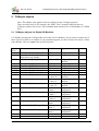
8.1.1.2 Numeric Operators
The numeric interpreter can handle the following simple operators (operators with two „inputs“ and
one „output“):
+
*
/
%
Add
Subtract
Multiply
Divide (w/o fraction)
Modulo (calculate the fraction from a division)
==
<>
<
<=
>
>=
compare:
compare:
compare:
compare:
compare:
compare:
&
&&
|
||
^
bitwise
boolean
bitwise
boolean
bitwise
~
!
bitwise NOT (prefix)
boolean NOT (prefix)
equal
not equal
less
less or equal
higher
higher or equal
AND
AND
OR
OR
EXOR
A very special operator from the „C“-Programming language is the „arithmetic if-then-else
statement“:
Syntax: <arg1>?<arg2>:<arg3>
Function:
if (<arg1> is not zero)
then result:=<arg2> ;
else result:=<arg3>
Boolean operators return either TRUE or FALSE, which are the values 1 and 0 here.
Inputs for boolean operators are TRUE if the argument is not zero and FALSE if the argument is
zero.
The priority of the operators determines the evaluation sequence. The interpreter only knows two
different priority levels, with the lower level for add, subtract, compare, „or“ etc and the higher
level for multiply, divide, modulo, „and“. In case of doubt, you should use braces. A braced
subexpression will always be evaluated with the highest priority.
© MKT / Doc.-Nr. 85110
Version 1.6
Page 47 / 69
Doc.-Nr. 85110
Programming tool for „User Programmable Terminal“ (UPT)
8.1.1.3 Numeric Variables
The numeric interpreter can only recognize variable name that begin with an upper-case letter (this
greatly simplifies the analyses for slow CPUs like 8051-compatible processors).
In the „UPT515“, names of variables must never exceed 8 characters length.
Usually the input of variables originates from a communication channel. But you may also assign
new values to a variable with the „@“-command of the command interpreter.
If a variable is used as an „application variable“ (which is connected to a communication channel),
you may access any of the following components :
.fl reads the „flag“-field of a variable,
.ut reads the „update timer“ of a variable,
.in reads the latest „input value“ from a communication channel,
.ed reads the „edited value“ which is currently visible on the display,
.ou reads the latest „output value“ for a communication channel,
.de reads the „default value“ from the variable definition table,
.mi reads the „minimum value“ from the variable definition table,
.ma reads the „maximum value“ from the variable definition table,
.fa reads the scaling factor from the variable definition table,
.di reads the scaling divisor from the variable definition table,
.of reads the scaling offset from the variable definition table,
.uo checks the „output update flags“ of the variable.
If you don’t specify a component name (or forget the dot after the variable name), the interpreter
uses the „edited value“ of the variable. The „edited value“ is also the only part of a variable that you
can modify directly by assigning a value.
© MKT / Doc.-Nr. 85110
Version 1.6
Page 48 / 69
Doc.-Nr. 85110
Programming tool for „User Programmable Terminal“ (UPT)
8.1.1.4 Numeric Functions
The numeric interpreter can only recognize function names that begin with a lower-case letter (this
greatly simplifies the analyses for slow CPUs like 8051-compatible processors).
All „Events“ can be evaluated as a part of an expression, because they are internally treated as
functions. The only difference between event-polling functions and the following functions is, that
event functions always return a boolean value, while „normal“ functions return a numeric value.
The following functions return numeric values:
cs: CAN-Status, bitcoded status of the CAN-controller
tv0 ... tv3 :
Timer Values of the user-programmable timers
ti: global time, incremented every 100ms
kd,ku,kb: Keyboard Functions. See chapter 7.13.1 (events).
lim(value,min,max) : Limit-function.
returns: value, if (value>=min) and (value<=max)
min,
if (value<min)
max,
if (value>max).
pn: reads the current page number.
inp: reads the current state of the UPT‘s digital inputs.
out: reads(!) the current state of the UPT‘s digital outputs.
pdo: some functions to control PDO-channels. See next chapter(s).
syn: some functions to control the CANopen-SYNC-message. See next chapter(s).
An up-to-date overview of all numeric functions can only be found in the help-system of the
programming tool !
© MKT / Doc.-Nr. 85110
Version 1.6
Page 49 / 69
Doc.-Nr. 85110
Programming tool for „User Programmable Terminal“ (UPT)
8.1.1.5 PDO Functions of the UPT-Interpreter
The numeric interpreter has some built-in functions that can be used to access the PDO-Channels.
Some of these functions may be used for event definitions or as part of numeric expressions.
You do not need these functions to read values from a received PDO or put values into a
transmitted PDO (connect Variables to a PDO-channel to do this !)
All PDO-functions described here require an „index“ to define which PDO-channel shall be used.
You may use pdo0, pdo1, pdo2 or pdo3. If you want to use a flexible index, use an
expression like pdo[PdoNr] or similar.
A dot (.) is used to separate the keyword „pdo“ from the pdo structure component as described later.
Most three-letter-component-names may be abbreviated by the first letter, for example
pdo[0].cnt is the same as pdo[0].c etc.
pdo[N].cnt
Returns the value of a counter. Use this function to find out how often a particular PDO has
been received or transmitted since power-on.
pdo[N].cyc
Returns the cycle time for the transmission of a PDO in milliseconds. You can also assign a
new TX cycle time for a PDO using a formal assignment like this: pdo[0].cyc = 1234 .
The TX cycle is similar to the "PDO Event Timer" as described in CANopen DS301 V4.0,
see object 0x1400 subindex 5.
pdo[N].dat[I]
Returns the current value of the [I]th data byte from PDO-channel N. You will usually
connect a variable to a PDO to extract one or more data bytes from the PDO’s data field (so
you usually do not need this function, only for very „special“ cases !).
Can also be modified as a formal assignment.
pdo[N].id
Returns the current CAN identifier used for a PDO.
You can also set a new CAN identifier for a PDO using a formal assignment like this:
pdo[0].id = 2047. BUT YOU SHOULD BE EXTREMELY CAREFUL WITH THIS
BECAUSE THE UPT'S INTERPRETER DOES NOT VERIFY DURING RUN-TIME IF A
VALID CAN-ID IS USED.
pdo[N].rcv
This numeric function checks if a PDO telegram has been received since the last function
call.
The flag will be reset internally by reading it. This function is intended to be used in event
definitions only. This function can be used for „watch“ or „guarding“-purposes like the
„syn.rcv“-function.
pdo[N].trn
This numeric function checks if a PDO telegram has been transmitted since the last function
call.
© MKT / Doc.-Nr. 85110
Version 1.6
Page 50 / 69
Doc.-Nr. 85110
Programming tool for „User Programmable Terminal“ (UPT)
The flag will be reset internally by reading it. This function is intended to be used in event
definitions only.
pdo[N].tx
Procedure to trigger the transmission of a PDO (immediately).
pdo[N].mod
This numeric function checks if a PDO telegram has been modified and not yet transmitted.
Returns: TRUE = The PDO’s data-field has been modified but not been transmitted yet
FALSE= The PDO’s data-field has not been modified since the last transmission.
pdo[N].syn
This numeric function returns the count of SYNC intervals of a paricular PDO channel since
its last transmission (or evaluation). This counter is internally required for CANopenTransmission-Types 2..241. See DS301 for more information.
© MKT / Doc.-Nr. 85110
Version 1.6
Page 51 / 69
Doc.-Nr. 85110
Programming tool for „User Programmable Terminal“ (UPT)
8.1.1.6 SYNC Functions of the UPT-Interpreter
The numeric interpreter has some built-in functions, that can be used to control or receive the
CANopen-SYNC-Message. Some of these functions may be used for event definitions or as part of
numeric expressions.
You do not need these functions if you simply want to receive SYNC messages (all PDO-channels
with synchronous transmission check SYNC-messages theirselves)
syn.rcv (abbreviated as syn.r )
This numeric function checks if a SYNC telegram has been received since the last function
call.
The flag will be reset internally by reading it. This function is intended to be used in event
definitions only.
For example, you may create a special „watcher“ for periodic SYNC receptions. Define
„syn.rcv“ as a global event and a timer-start-command like „ts0(50)“ as the corresponding
reaction. This will (re)start Timer 0 for 500ms on every SYNC reception. Define annother
global event („t0“) and reaction (like g“NoSync“). Create a display page named „NoSync“.
This page will be displayed when the UPT does not receive SYNC telegrams anymore.
syn.cnt (abbreviated as syn.c )
This numeric function returns the value of a counter for all SYNC telegrams. You may use
this value for testing purposes (for example, to find out if the UPT received any SYNC
telegrams at all without resetting the „syn.rcv“-flag).
© MKT / Doc.-Nr. 85110
Version 1.6
Page 52 / 69
Doc.-Nr. 85110
Programming tool for „User Programmable Terminal“ (UPT)
8.2 String Functions
In May 2000, a „text-array“ has been implemented. Some string functions can be used to read
single lines from this text array.
Most of the string functions will begin with the letter „s“ to tell them from numeric functions.
At the present time (May 2000), string functions can only be called from text-display-commands
(see chapter 7.10.2).
sa[ <text-array-INDEX> ]
Returns one line of the Text-Array specified by its array-index.
sr[ <text-array-REFERENCE> ]
Returns one line of the Text-Array specified by the user-reference-number.
The REFERENCE-Number is entered into the text-array along with the text string (see
chapter 7.18). Text-Reference-Numbers may be any 32-bit-values, they do not even have to
be sorted. The Interpreter performs a simple „linear“ search for the reference-number.
This makes the „sr[]“-Function a very efficient tool to convert arbitrary „error codes“ into
„text messages“ on the screen.
(Maybe there are more functions which have not yet been described here...
check the Help System of the UPT Programming Tool if there‘s more info !)
© MKT / Doc.-Nr. 85110
Version 1.6
Page 53 / 69
Doc.-Nr. 85110
Programming tool for „User Programmable Terminal“ (UPT)
8.3 Interpreter Commands
The UPT’s firmware has a built-in system interpreter which is used for:
event reaction methods, which are usually „goto“ or „call“ -commands
graphic output commands for complex display pages
commands to control signal LEDs ,
commands to control the four „User“-timers
assign command to set a new value of a variable
Some interpreter commands (procedures) expect a list of parameters, others don’t require any
parameters.
Most parameters can be numeric expressions .
For testing purposes you may send commands to the interpreter using the status bar of the
programming tool (or via the new „Test/Command“-window).
8.4 Program control commands
8.4.1 Goto, Call and Return
These commands for the UPT’s built-in command interpreter are used to switch between pages of
your application. All of these commands must be entered in abbreviated form (single letter).
Syntax:
goto:
g<page-number> or g”page-name”
call:
c<page-number> or c”page-name”
return: r
Goto and Call both switch to another display page, which may be defined by the page-number or
(preferrably) by the page-name.
Call also saves the number of the current (old) page on a special „call-stack“ before switching to
the new page. The „called“ page may switch later switch back to the „calling“ page using the
„return“ command.
Call + Return should always be used together. If you enter a page with a „call“, you should also
„return“ to the caller and not jump back to the caller with a „goto“ (this would cause an overflow of
the call stack, furthermore it does not make too much sense).
The reason to use Call & Return instead of Goto is when many different callers use a common
„subpage“ (like a „subroutine“). After the „subroutine“ has done its work (for example display an
error message and wait for a key), the normal operation can resume.
Note: Neither Goto nor Call have an effect if the target (=new page) is the „current“ (=old) page.
© MKT / Doc.-Nr. 85110
Version 1.6
Page 54 / 69
Doc.-Nr. 85110
Programming tool for „User Programmable Terminal“ (UPT)
8.5 The assign-command
This command is used to assign a new value for a variable.
Syntax:
@<Varname> = <expression>
Example:
@Ypos=(Voltage*63)/230
Notes:
You can only assign values to variables that have been defined in the variable table.
You should not assign values to variables that get their values from a communication channel.
© MKT / Doc.-Nr. 85110
Version 1.6
Page 55 / 69
Doc.-Nr. 85110
Programming tool for „User Programmable Terminal“ (UPT)
8.6 Graphic output commands
8.6.1 The ICON-command (ic)
This graphic command is used to draw a small picture („icon“) on the screen.
Syntax:
ic(<icon-name>, <x-position>, <y-position>)
The icon-name must match the name that you defined on the icon-page. Otherwise the display-listinterpreter inside the programming too will generate an error.
8.6.2 The LINE-command (li)
This graphic command is used to display a graphic line on the screen.
Syntax:
li( <x1>, <y1>, <x2>, <y2>, ... )
8.6.3 The PIXEL-command (pi)
This graphic command is used to display a single pixel on the screen.
Syntax:
pi( <x>, <y> )
© MKT / Doc.-Nr. 85110
Version 1.6
Page 56 / 69
Doc.-Nr. 85110
Programming tool for „User Programmable Terminal“ (UPT)
8.6.4 The FRAME-command (fr)
This graphic command is used to display a rectangular frame on the screen.
The interior of the frame will not be affected by this command (it remains unchanged).
Syntax:
fr( <x1>, <y1>, <x2>, <y2> )
where
x1 = left border
y1 = top
x2 = right border
y2 = bottom
8.6.5 The FILL RECTANGLE-command (fi)
This graphic command is used to fill a rectangular shape on the screen.
Syntax:
fi( <x1>, <y1>, <x2>, <y2> [ , <pattern0>, <pattern1> ] )
where
x1 = left border
y1 = top
x2 = right border
y2 = bottom
pattern0, pattern1 = optional filling pattern, default=0xFF=solid.
All „old“ contents of the rectangular area will be overwritten by this command, unless you use a
draw mode that does not write both display „pages“ (=blink phases).
The optional filling pattern allows drawing rectangles with different shades. Both patterns are 8Bit-Masks, where a „1“-Bit will be „set“, a „0“-Bit will be reset. <Pattern0> will be used to fill all
even graphic lines, <Pattern1> will be used to fill all odd graphic lines. Some examples of useful
filling patterns are:
fi(10,10,30,20, 0xFF, 0xFF)
will draw a „solid „black“ rectangle
fi(10,22,30,30, 0xFF, 0x00)
will draw a rectangle that consists of horizontal lines
fi(10,32,30,40, 0x55, 0x55)
will draw a rectangle that consists of thin vertical lines
fi(10,42,30,50, 0x55, 0xAA)
will draw a „50 percent gray shaded“ rectangle
If you omit the filling patterns, the interpreter assumes that you want to draw a solid rectangle (the
used filling pattern will be „0xFF, 0xFF“ then).
© MKT / Doc.-Nr. 85110
Version 1.6
Page 57 / 69
Doc.-Nr. 85110
Programming tool for „User Programmable Terminal“ (UPT)
8.6.6 The Draw Mode-command (dm)
This graphic command is used to set the draw mode for all following graphic output commands.
The display in the UPT-515 has two „video-pages“, which are alternated every 0.5 seconds to
achieve „Blink“-Effects etc.
Syntax:
dm( <new draw mode> )
valid parameters for the draw mode are:
0: Standard-output into both video-pages
1: „Page1“, output only into page 1
2: „Page2“, output only into page 2
3: Blink1 (draw into page1, erase in page 2)
4: Blink2 (draw into page2, erase in page 1)
5: inverse output into both video-pages
6: inverse output only into page 1
7: inverse output only into page 2
8: Inverse blinking 1 (page 1 normal, page 2 inverse)
9: Inverse blinking 2 (page 1 invers, page 2 normal)
Note: Color displays do not have two video pages. Some draw modes are not available on such
displays (for example the UPT-167 „COLOR“).
© MKT / Doc.-Nr. 85110
Version 1.6
Page 58 / 69
Doc.-Nr. 85110
Programming tool for „User Programmable Terminal“ (UPT)
8.7 Other Interpreter Commands
8.7.1 The “led”-Command
The UPT’s firmware of some variants of the User Programmable Terminal has one command to
control the a built-in signal-LEDs.
Syntax:
led( <led-number>, <led-blink-pattern> )
or abbreviated:
le ( <led-number> , <led-blink-pattern> )
Parameters:
<led-number> is the index of the LED that shall be switched: 0=1st LED, 1=2nd LED, ....
<led-output-pattern> is an eight-phase-code for the LED blink „rhythm“. Every bit of this pattern
controls a 100ms-Interval. After a cycle of 8 * 100ms the whole cycles starts again from the
beginning. All LED-blink-cycles are „synchonized“: that means, if two LEDs have the same blinkpattern they will flash exactly at the same time.
Here are some useful blink patterns:
0x00
LED is OFF (this is the default state after power-on)
0xFF
LED is permanently ON
0xF0
LED blinks slowly: 400ms ON, 400ms OFF and so on.
0x55
LED blinks quickly: 100ms ON, 100ms OFF and so on.
0x01
LED gives short flash pulses: 100ms ON, 700ms OFF...
© MKT / Doc.-Nr. 85110
Version 1.6
Page 59 / 69
Doc.-Nr. 85110
Programming tool for „User Programmable Terminal“ (UPT)
8.7.2 The “out”-Command
This command is used to control the state of the UPT’s built-in digital outputs.
There are two different „flavours“ of this command:
out(<8-bit-value>)
This format is used to control all digital outputs at once. Bit 0 controls the first output and so
on.
out(<output_nr>, <new_state> )
This format is used to control the state of one single output.
Examples:
out($FF)
turns all outputs on
out($00)
turns all outputs off
out(0, 1)
turns the first output on
out(3, 0)
turns the fourth output off
out(out^$02) inverts the state of the second output.
Notes:
There is not only an output-command to set the digital outputs, but also a function named
„out“ that reads back the current state of the digital outputs.
Not all devices used as „User Programmable Terminal“ have own digital outputs. To access
outputs on a remove I/O-module, you must use a communication channel.
Perhaps your UPT515 only has four digital outputs and six digital inputs.
The UPT’s digital inputs and outputs are „simulated“ by the programming tool. The state of the
outputs is displayed as round shapes in the simulator window.
© MKT / Doc.-Nr. 85110
Version 1.6
Page 60 / 69
Doc.-Nr. 85110
Programming tool for „User Programmable Terminal“ (UPT)
8.7.3 Timer commands and functions
The UPT’s firmware has some built-in functions and procedures to control four „User Timers“.
These timers can be used to generate time intervals of up to 65534*100ms (which is more than one
hour). These timers are intended to produce events , but you may also use them for any other
purpose.
Timer procedures:
ts0 ... ts3 (timer start)
Starts one of the four „User Timers“ for a given time interval. The timer will count down
from the starting value to zero, when it generates a timer event. Starting a timer again before
it reaches zero will prevent the timer event. The maximum time for a user timer is 65534 ( *
100 ms).
Syntax: ts0(<timer starting value in 100ms>)
Example: ts0(40) starts the first timer for a time of 4 seconds. After 4 seconds there will be
a „t0“ event which you can handle on one of your event definitions (global or local).
tr0 ... tr3 (timer reset)
Resets one of the four „User Timers“. This will stop the timer and prevent the generation of
a timer event. Internally, a timer that has been reset contains the value 0x0FFFF which
means „stopped“. This value is the default value for all timers after power-on.
Timer functions:
t0 ... t3
Checks if a user-timer has „run off“, that means Timer 0 ... Timer 3 has been decremented
from 1 to 0 . Returns: Zero (=FALSE) if the timer is not running or has not yet reached
zero,
One (=TRUE) if the timer has counted down to zero (where it stops)
tv0 ... tv3 (timer value)
Reads the current value of a user-timer. This value runs from the started value down to zero
(decremented every 100 ms).
ti (global time)
Reads the current „system clock“ as a 32-bit value. The system clock is a 32-bit-counter
incremented every 100 ms. It does not depend on the four „user“-timers and can neither be
stopped nor modified by the user program. After more than 6 years of uninterrupted
operation of the User Programmable Terminal, this value will become negative because it
will be incremented from ((2 power 31)-1) to (2 power 31) which is a negative value for 32bit-Numbers. After power-on of the UPT, the global time always starts at zero.
Some demo-programs use this function to show a company logo for a short while after
power-on.
© MKT / Doc.-Nr. 85110
Version 1.6
Page 61 / 69
Doc.-Nr. 85110
© MKT / Doc.-Nr. 85110
Programming tool for „User Programmable Terminal“ (UPT)
Version 1.6
Page 62 / 69
Doc.-Nr. 85110
Programming tool for „User Programmable Terminal“ (UPT)
9. CANopen objects
Note: This chapter only applies to devices which use the CANopen protocol.
There are other devices (for example, the "MKT-View" terminal) which do not use
CANopen, and use low-level CAN communication described in a CAN database ("CANdb
file").
9.1 CANopen objects for Digital I/O-Modules
CiA DS401 specifies the CANopen Device Profile for I/O-Modules. If you want to connect any of
these objects via SDO to a variable of your terminal program, you have to know the object’s index
and subindex. Here are some of the specified objects:
Index
(hex)
0x6000
0x6006
Name
Subindizes
Type
Access
0,1 .. max.4
0, 1.. max.4
Unsigned8
Unsigned8
ro
rw
0x6020
Read State [of] 8 Input Lines
Input Interrupt Mask [for] 8
Input Lines, any change
Read State [of] 1 Input Line
0, 1.. max.32
ro
0x6100
0x6120
0x6200
0x6206
0x6207
0x6220
Read State [of] 16 Input Lines
Read State [of] 32 Input Lines
Write State [for] 8 Output Lines
Fault Mode [for] 8 Output Lines
Fault State [for] 8 Output Lines
Write State [for] 1 Ouput Line
0x6250
Fault Mode [for] 1 Output Line
0x6260
Fault State [for] 1 Output Line
0x6300
Write State [for] 16 Output Lines
0x6306
Fault Mode [for] 16 Output Lines
0x6307
Fault State [for] 16 Output Lines
0x6320
Write State [for] 32 Output Lines
0x6326
Fault Mode [for] 32 Output Lines
0x6327
Fault State [for] 32 Output Lines
0, [1, 2]
0, max. 1
0, 1..max.4
0, 1..max 4
0, 1..max 4
0,
1.. max.32
0,
1..max.32
0,
1..max.32
0,
1..max.2
0,
1..max 2
0,
1..max 4
0,
max.1
0,
max 1
0,
max 1
Unsigned8,
Boolean
Unsigned16
Unsigned32
Unsigned8
Unsigned8
Unsigned8
Unsigned8,
Boolean
Unsigned8,
Boolean
Unsigned8,
Boolean
Unsigned8,
Unsigned16
Unsigned8,
Unsigned16
Unsigned8,
Unsigned16
Unsigned8,
Unsigned32
Unsigned8,
Unsigned32
Unsigned8,
Unsigned32
© MKT / Doc.-Nr. 85110
Version 1.6
ro
ro
rw
rw
rw
rw
rw
rw
rw
rw
rw
rw
rw
rw
Page 63 / 69
Doc.-Nr. 85110
© MKT / Doc.-Nr. 85110
Programming tool for „User Programmable Terminal“ (UPT)
Version 1.6
Page 64 / 69
Doc.-Nr. 85110
Programming tool for „User Programmable Terminal“ (UPT)
9.2 CANopen objects for Analog I/O-Modules
CiA DS401 specifies the CANopen Device Profile for I/O-Modules with analog inputs and/or
outputs. If you want to connect any of these objects via SDO to a variable of your terminal
program, you have to know the object’s index and subindex. Here are some of the specified objects:
Index
(hex)
0x6401
0x6411
0x6420
0x6421
0x6423
0x6424
0x6425
0x6426
0x6443
0x6444
Name
Subindizes
Type
Access
Reads value of the input
channel (not converted)
Writes value of the output channel (not
converted)
Set Analogue Input Range
0
1 [... 4]
0
1 [... 4]
0
1 [... 4]
0
1 [... 4]
0
0
1 [... 4]
Unsigned 8
Unsigned16
Unsigned8
Unsigned 16
Unsigned8
Unsigned 16
Unsigned 8
Unsigned 8
Boolean
Unsigned8
Unsigned 32
ro
0
1 [... 4]
Unsigned8
Unsigned 32
rw
0
1 [...4]
Unsigned8,
Unsigned 32
rw
0,1
0
1
Unsigned8
Unsigned 8
Unsigned 32
rw
rw
Determines which events cause an
interrupt for a specific channel
Globally enable/disable Interrupt
When enabled, interrupt triggered
when analogue input rises above this
value (not converted)
When enabled, interrupt triggered
when analogue input falls below this
value (not converted)
When enabled, interrupt triggered
when analogue changes by more than
thisvalue from previous reading (rising
or falling) (not converted)
Output Fault Mode
Default Output Fault value
(unconverted)
rw
rw
rw
rw
rw
More information about these objects can be found in DS401.
© MKT / Doc.-Nr. 85110
Version 1.6
Page 65 / 69
Doc.-Nr. 85110
Programming tool for „User Programmable Terminal“ (UPT)
9.3 CANopen objects inside the UPT
All information inside the User Programmable Terminal can be accessed via CAN-Bus as part of
the manufacturer specific profile of a CANopen object dictionary. The programming tool uses these
objects to transfer your „user program“ into the terminal.
As you upload or download a program into/from the terminal, there may be some error messages
with a CANopen-index in the range of 0x5100 to 0x57FF. The possible cause for such errors may
be a compatibility problem between an „old“ terminal and a „new“ programming software (or vice
versa). The following table may help to trace such errors:
CANopen-Index
0x5080
0x5101
0x5102
0x5103
0x5104
0x5105
0x5106
0x5180
0x5200..52ff
0x5300..53ff
0x5400..54ff
0x5500..55ff
0x5600..56FF
0x5700..57FF
0x5800..58FF
Contents
MKT’s CAN snapshot utility
Constants (max number of variables, etc.)
Names of the terminal’s keys
General Settings (number of display pages, etc.)
Run Mode (Run, Stop, Transfer etc)
current Display-Page
Save Permanent (transfers RAM data to FLASH or EEPROM)
global Events-Definitions (as strings)
SDO-Channel-Definitions (as strings)
PDO-Kanal-Definitions (as strings)
Variable-Definitions (as strings)
Display-Page-Definitions (as strings)
Icon-Definitions (hex-coded strings)
Text-Array-Definitions (strings)
reserved for other 'arrays' (numeric)
0x5C00..5C0F
reserved for onboard frequency counter etc
The data format of the definition-tables is very similar to the text-file-format that is used to save
your UPT-program on a disk drive. In fact, we use the same conversion routines in the UPT as in
the programming tool.
Since May 2001, some UPT firmware versions have a few objects from the CANopen
communication profile implemented (DS301, Object index range 0x1000 – 0x1BFF). These
objects only exist to detect a UPT device in a network. It is impossible to modify UPT settings via
these objects. The PDO communication- and mapping objects do not carry useful information yet.
CANopen-Index
0x1000
0x1018
0x1018.1
0x1018.2
0x1018.3
0x1018.4
Contents
Device Type
Identity Object
MKT’s vendor ID
Product Code
Revision Number
Serial Number
© MKT / Doc.-Nr. 85110
(Only DS301 at the moment)
(0x004D4B54)
(70055=UPT515, etc)
(ex: 0x00010002 = V01.02)
(expect this to be ZERO)
Version 1.6
Page 66 / 69
Doc.-Nr. 85110
© MKT / Doc.-Nr. 85110
Programming tool for „User Programmable Terminal“ (UPT)
Version 1.6
Page 67 / 69
Doc.-Nr. 85110
Programming tool for „User Programmable Terminal“ (UPT)
10. Transferring the application into the programmable device
To transfer the display application (*.upt or *.cvt) into the programmable device ("display"), you
have different choices depending on the available hardware. Details about this can only be found in
the Online Help System (HTML) . Here just a few examples:
•
•
•
•
Transfer via memory card (SD or Compact Flash)
Transfer via RS-232 (unfortunately, this reliable and easy-to-use interface has been replaced
with the flawed, unreliable, and utterly complex USB on most PCs...)
Transfer via CAN bus (requires a CAN bus interface, or another device equipped with a
CAN-via-UDP server which can act as a bridge between Ethernet (LAN) and CAN)
Transfer directly via Ethernet (LAN)
In addition to the application (*.upt, *.cvt), other files may have to be loaded into the device, for
example certain audio files, user defined fonts, etc. If you don't have a memory card reader
connected to your PC, you can used the file transfer utility which is integrated in the programming
tool. Details about this 'File Transfer Utility' are also in the online help system; see document
filetransfer_01.htm (englisch) or filetransfer_49.htm (deutsch).
11. Error Messages
11.1 SDO error codes
Here are some error codes that may occur during program upload or download.
Most of these error codes are taken from CANopen DS301 V4.
Some of these errors may also be caused by external devices on the CAN bus.
For a more sophisticated explanation of these errors you should check the CiA literature or other
CAN protocol descriptions.
Error Code
0x05030000
0x05040000
0x05040001
0x05040002
0x05040003
0x05040004
0x05040005
0x06010000
0x06010001
0x06010002
0x06010047
0x06020000
0x06040041
0x06040042
0x06040043
Meaning
TOGGLE-BIT NOT ALTERNATED
SDO-PROTOCOL TIMED OUT
COMMAND SPECIFIER NOT VALID OR UNKNOWN
INVALID BLOCK SIZE
INVALID SEQUENCE NUMBER
CRC ERROR
OUT OF MEMORY
UNSUPPORTED ACCESS TO AN OBJECT
ATTEMPT TO READ A WRITE-ONLY OBJECT
ATTEMPT TO WRITE A READ-ONLY OBJECT
UNSUPPORTED ACCESS, INTERNAL INCOMPATIBLE
OBJECT DOES NOT EXIST IN DICTIONARY
OBJECT CANNOT BE MAPPED TO THE PDO
MAPPED OBJECTS WOULD EXCEED PDO LENGTH
GENERAL PARAMETER INCOMPATIBILITY
© MKT / Doc.-Nr. 85110
Version 1.6
Page 68 / 69
Doc.-Nr. 85110
0x06040047
0x06060000
0x0606002F
0x06070010
0x06070010
0x06070012
0x06070013
0x06090011
0x06090030
0x06090031
0x06090032
0x06090036
0x08000000
0x08000020
0x08000021
0x08000022
0x08000023
Programming tool for „User Programmable Terminal“ (UPT)
GENERAL INTERNAL INCOMPATIBILITY
ACCESS FAILED DUE TO HARDWARE ERROR
ACCESS FAILED DUE TO CAN ERROR
DATA TYPES DO NOT MATCH
LENGTH OF PARAM DOES NOT MATCH
LENGTH OF PARAM TOO HIGH
LENGTH OF PARAM TOO LOW
SUBINDEX DOES NOT EXIST
VALUE RANGE EXCEEDED
VALUE RANGE TOO HIGH
VALUE RANGE TOO LOW
MAXIMUM VALUE IS LESS THAN MINIMUM VALUE
GENERAL ERROR
DATA CANNOT BE TRANSFERRED TO APPLICATION
.. due to local control
.. due to device state
OBJECT DIRECTORY GENERATION FAILS
© MKT / Doc.-Nr. 85110
Version 1.6
Page 69 / 69