1
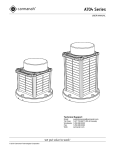
A650 WIRELESS
USER MANUAL
Technical Support:
Email:
Toll Free:
Worldwide:
Fax:
Web:
© 2012 Carmanah Technologies Corporation
[email protected]
1.877.722.8877 (US & Canada)
1.250.380.0052
1.250.380.0062
carmanah.com
A650 WIRELESS
USER MANUAL
Contents
1.0
Safety & Usage ..................................................................................................................................................3
1.1
Viewing Precautions ........................................................................................................................................3
1.2
Battery Precautions .........................................................................................................................................3
1.3
Wireless Precautions .......................................................................................................................................4
1.4
Regulatory .......................................................................................................................................................4
1.5
Warranty Disclaimer ........................................................................................................................................4
2.0
Introduction .......................................................................................................................................................5
2.1
Features ..........................................................................................................................................................5
2.2
Applications .....................................................................................................................................................5
3.0
Installation .........................................................................................................................................................6
3.2
Bird Deterrent ..................................................................................................................................................7
3.3
Antenna ...........................................................................................................................................................8
3.5
Location ...........................................................................................................................................................9
3.7
Fastening .......................................................................................................................................................10
4.0
Operation .........................................................................................................................................................12
4.1
Theory of Operation.......................................................................................................................................12
4.2
Modes ............................................................................................................................................................12
4.3
Features ........................................................................................................................................................14
5.0
Maintenance ....................................................................................................................................................18
5.1
Inspection ......................................................................................................................................................18
5.2
Storage & Battery Charging ..........................................................................................................................18
5.3
Battery Replacement .....................................................................................................................................19
5.4
Recycling .......................................................................................................................................................23
6.0
Troubleshooting ..............................................................................................................................................24
7.0
Warranty ...........................................................................................................................................................25
8.0
Appendices ......................................................................................................................................................26
8.1
Glossary ........................................................................................................................................................26
8.2
Specifications ................................................................................................................................................27
© 2012 Carmanah Technologies Corporation
2
A650 WIRELESS
USER MANUAL
1.0
Safety & Usage
The following symbols indicate important safety warnings and precautions throughout this manual:
WARNING indicates that serious bodily harm or death may result from failure to adhere to the
precautions.
CAUTION indicates that damage to equipment may result if the instructions are not followed.
NOTE suggests optimal conditions and provides additional information.
WIRELESS features and functions that require a Handheld Controller.
1.1
Viewing Precautions
Do not view an actively emitting infrared or visible light from the side of the light (close to or on
beam) from a range of less than 4 ft. (1.2 m).
A safe limit for near-infrared viewing, established by the American Conference of Governmental and Industrial
Hygienists (ACGIH), is 65 mW/in2 (10 mW/cm2) as the maximum exposure limit for viewing for up to 16 minutes.
This power density can be produced at the lens surface when actively emitting infrared light.
1.2
Battery Precautions
Use extreme caution when handling the light. This product is capable of generating enormous shortcircuit currents. Remove all jewelry (bracelets, metal-strap watches, rings) before attempting to
handle or remove the batteries.
Charge your battery periodically. Permanent damage and reduced capacity will result if the battery
is not correctly maintained.
The rate of battery self-discharge is very dependent upon temperature. The warmer the temperature, the faster the
batteries will discharge.
Lights that have been stored will usually require a top-up charge before they are put into service. The most
accurate battery health status reading is obtained when the unit has been in a dark location and in off mode for at
least 24 hours.
© 2012 Carmanah Technologies Corporation
3
A650 WIRELESS
USER MANUAL
1.3
Wireless Precautions
Keep the Handheld Controller at a distance of at least 3 ft. (1 m) from the antennas of lights or other
Handheld Controllers. It sends out a powerful radio signal that could damage sensitive receiver
circuitry if operated at close range.
1.4
Regulatory
This device complies with Part 15 of the FCC Rules. Operation is subject to the following two conditions:
1. This device may not cause harmful interference, and
2. This device must accept any interference received, including interference that may cause undesired
operation.
This equipment has been tested and found to comply with the limits for a Class B digital device, pursuant to Part 15
of the FCC Rules. These limits are designed to provide reasonable protection against harmful interference in a
residential installation. This equipment generates, uses, and can radiate radio frequency energy and, if not installed
and used in accordance with the instruction manual, may cause harmful interference to radio communications;
however, there is no guarantee that interference will not occur in a particular installation. If this equipment does
cause harmful interference to radio or television reception, which can be determined by turning the equipment off or
on, the user is encouraged to try to correct the interference by one or more of the following measures:
•
Reorient or relocate the receiving antenna;
•
Increase the separation between the equipment and receiver;
•
Connect the equipment into an outlet on a circuit different from that to which the receiver is connected;
•
Consult the dealer or an experienced radio/TV technician for help.
This Class [B] digital apparatus complies with Canadian ICES-003.
Cet appareil numérique de la classe [B] est conforme à la norme NMB-003 du Canada.
1.5
Warranty Disclaimer
This manual will familiarize you with the features and operating standards of the product. Failure to
comply with the use, storage, maintenance, or installation instructions detailed in this manual could
void the user warranty.
Changes or modifications not expressly approved by the party responsible for compliance could void
the user’s authority to operate the equipment. Installation work must be done by a qualified
person(s) in accordance with all application local codes and standards.
© 2012 Carmanah Technologies Corporation
4
A650 WIRELESS
USER MANUAL
2.0
2.1
Introduction
Features
The A650 Wireless Solar Aviation Light has the following features:
•
Self-contained, high-performance, solar-powered light source
•
Wireless control range of up to 2.5 miles (4 km) with available Handheld Controller
•
Easy-to-install and low-maintenance with long-life light emitting diodes (LEDs)
•
Available in red, green, yellow, white, and blue visible LED output colors
•
Read-only On-Board User Interface (OBUI)
•
Intelligent Energy Management System (EMS)
•
Visible LED and night vision goggle (NVG)-compatible infrared (IR) LED outputs
•
Replaceable battery pack
2.2
Applications
The A650 Wireless has the following applications:
•
Taxiway edge
•
Apron edge
•
Emergency airfield
•
Helipad
•
Construction barricades
•
Obstruction
© 2012 Carmanah Technologies Corporation
5
A650 WIRELESS
USER MANUAL
3.0
Installation
The A650 Wireless includes:
•
A650 Wireless
•
Antenna
•
Bird deterrent
•
Quick Start Guide
The manual (this document) is shipped independently. It is available for download from www.carmanah.com
© 2012 Carmanah Technologies Corporation
6
A650 WIRELESS
USER MANUAL
3.2
Bird Deterrent
The A650 Wireless can have up to 2 bird deterrents. Install the deterrents before fastening the light down. Do not
install a bird deterrent in the mounting foot directly below the antenna.
© 2012 Carmanah Technologies Corporation
7
A650 WIRELESS
USER MANUAL
3.3
Antenna
Grip the antenna by its metal base and hand-tighten it onto the antenna connector.
The effective range of the wireless control system is 2.5 miles (4 km). Wireless range is greatly affected by use
and location. To achieve the best wireless range:
•
Handheld Controller antenna is parallel to the light’s antenna
•
Elevate the Handheld Controller’s antenna
•
Ensure surrounding grass and foliage is trim
•
Clear line-of-sight between antennas
© 2012 Carmanah Technologies Corporation
8
A650 WIRELESS
USER MANUAL
3.5
Location
Year-round, unrestricted solar exposure is critical to long-term performance.
Shade dramatically reduces the ability of the light to charge its battery.
Year-round sun: During the winter, the sun is lower on the horizon. Because the angle of the sun changes with
the seasons, you must be aware that obstructions such as trees, buildings, and mountains that do not shade the
solar panel during the summer may shade it during the winter.
Cooler is better: The battery lasts longest if you can minimize its exposure to high temperatures. Choose a
location that is away from hot, dark colored surfaces like asphalt or black steel plate. Mounting kits are available
that elevate the light and can help reduce the temperature of the battery.
Flat: Ensure the mounting surface is flat and level. The surfaces in contact with the 3 mounting feet must be flat to
within 0.12 in. (3 mm) of one another.
© 2012 Carmanah Technologies Corporation
9
A650 WIRELESS
USER MANUAL
3.7
Fastening
The A650 Wireless has 3 mounting feet with holes for 0.25 in. (6 mm) fasteners. The mounting holes have a bolt
circle of 5.9 in. (150 mm). Fasteners are not included but are available as kits.
© 2012 Carmanah Technologies Corporation
10
A650 WIRELESS
USER MANUAL
© 2012 Carmanah Technologies Corporation
11
A650 WIRELESS
USER MANUAL
4.0
4.1
Operation
Theory of Operation
During daylight, the solar panel charges the battery using the Energy Management System (EMS). The capacity of
the battery ensures that even with poor levels of sunlight over an extended period, the light has enough reserve
power to continue to perform reliably.
Stored battery energy is then available to power the output LED in one of several modes. These modes are
selected using the Handheld Controller. The most commonly used are Autonomous and Temporary Modes.
The Handheld Controller contains a 900 MHz radio that transmits commands to a receiving radio inside the A650
Wireless. For Handheld Controller button sequences for the below modes and features, see the Handheld
Controller manual.
4.2
Modes
4.2.1 Autonomous Mode
In Autonomous Mode, the output LED turns on from dusk-to-dawn and turns off during daylight. The change from
dusk-to-dawn or dawn-to-dusk is known as a transition. A built-in ambient brightness sensor detects transitions.
Autonomous Mode setting is determined by a map in the Appendices.
Correct setting is important to ensure sustainable, year-round operation.
The Autonomous Mode setting is selected via the Handheld Controller:
Setting
Intensity
Output LED
Flashing
Active
AUTO LOW
Low
Visible
No
Dusk-to-dawn
AUTO MED
Medium
Visible
No
Dusk-to-dawn
AUTO HIGH
High
Visible
No
Dusk-to-dawn
AUTO LOW IR
Low
Infrared
No
Dusk-to-dawn
AUTO MED IR
Medium
Infrared
No
Dusk-to-dawn
AUTO HIGH IR
High
Infrared
No
Dusk-to-dawn
AUTO LOW FLASH
Low
Visible
0.25 sec. on, 0.75 sec. off
Dusk-to-dawn
AUTO MED FLASH
Medium
Visible
0.25 sec. on, 0.75 sec. off
Dusk-to-dawn
AUTO HIGH FLASH
High
Visible
0.25 sec. on, 0.75 sec. off
Dusk-to-dawn
AUTO LOW IR FLASH
Low
Infrared
0.25 sec. on, 0.75 sec. off
Dusk-to-dawn
AUTO MED IR FLASH
Medium
Infrared
0.25 sec. on, 0.75 sec. off
Dusk-to-dawn
AUTO HIGH IR FLASH
High
Infrared
0.25 sec. on, 0.75 sec. off
Dusk-to-dawn
© 2012 Carmanah Technologies Corporation
12
A650 WIRELESS
USER MANUAL
Factory default is AUTO LOW, visible LED, non-flashing.
4.2.2 Temporary Mode
In Temporary Mode, the output LED is directly controlled by the Handheld Controller. A Temporary Mode activation
interrupts other modes and ignores transitions. This activation lasts for 15 min. and then the light reverts to its
previous Autonomous Mode.
Maximum number Temporary Mode activations per day is determined by a map in the Appendices.
It is possible to use more Temporary Mode activations per day. The battery will then require more
than 1 day of solar energy to fully charge.
The Temporary Mode setting is selected via the Handheld Controller:
Setting
Intensity
Output LED
Flashing
Active
TEMP LOW
Low
Visible
No
15 min.
TEMP MED
Medium
Visible
No
15 min.
TEMP HIGH
High
Visible
No
15 min.
TEMP LOW IR
Low
Infrared
No
15 min.
TEMP MED IR
Medium
Infrared
No
15 min.
TEMP HIGH IR
High
Infrared
No
15 min.
TEMP LOW FLASH
Low
Visible
0.25 sec. on, 0.75 sec. off
15 min.
TEMP MED FLASH
Medium
Visible
0.25 sec. on, 0.75 sec. off
15 min.
TEMP HIGH FLASH
High
Visible
0.25 sec. on, 0.75 sec. off
15 min.
TEMP LOW IR FLASH
Low
Infrared
0.25 sec. on, 0.75 sec. off
15 min.
TEMP MED IR FLASH
Medium
Infrared
0.25 sec. on, 0.75 sec. off
15 min.
TEMP HIGH IR FLASH
High
Infrared
0.25 sec. on, 0.75 sec. off
15 min.
4.2.3 Standby Mode
Standby Mode turns off the output LED and waits for the next transition. After a transition, the light enters its
previous Autonomous Mode.
4.2.4 Lights Off Mode
Lights Off Mode turns off the output LED indefinitely until it receives a command to turn them on. Lights Off Mode
is entered via the Handheld Controller and is different than sliding the switch to OFF.
© 2012 Carmanah Technologies Corporation
13
A650 WIRELESS
USER MANUAL
4.2.5 Emergency Mode
Emergency Mode sets all lights in all groups to emergency flash. Emergency flash is TEMP HIGH FLASH. After
15 min., the lights revert to their previous Autonomous modes.
4.2.6 ARCAL Mode
The Aircraft Radio Control of Aerodrome Lighting (ARCAL) feature works in conjunction with an ARCAL VHF
receiver to allow aircraft pilots to control the airfield lights.
4.3
Features
4.3.1 On-Board User Interface
The On-Board User Interface (OBUI) is viewable through the bottom cover. Slide the switch ON or press a button
on the OBUI to turn on the display.
The OBUI has no user editable parameters and provides read-only feedback:
What is the battery’s state of
charge?
Is the wireless system on?
Are the infrared output LEDs on?
Batt
Rf
Ir
Good
Good, deploy the light
cHrg
cHrg
Charge the battery before
deploying
Lo
LVD is entered; charge the
battery before deploying
bad
Bad battery needs replacing
on
Ready to receive wireless
commands
ofF
Will not receive wireless
commands
err
Radio failure
on
off
What group ID is the light part of?
GpId
GpId
1 2 3 4 5 6 7 8
Is Universal Code Sequence on?
UCs
UCs
on
off
System version?
© 2012 Carmanah Technologies Corporation
Info
0.0
0.0
0.0
0
14
A650 WIRELESS
USER MANUAL
4.3.2 Switch
The switch must be ON ( I ) to respond to Handheld Controller commands:
•
Light enters its last mode
Switch the light OFF ( O ) to ship or store it:
•
Will not respond to wireless control and will not be able to turn on its output LEDs
•
Stores the last mode
•
Sunlight will continue to charge the battery
•
Does not turn itself off after 24 hours of darkness
4.3.3 Automatic Light Control
Automatic Light Control (ALC) is a patented algorithm that matches the light’s energy consumption to its energy
storage. As the battery state of charge diminishes, ALC decreases the output LED intensity. ALC has 9 intensity
© 2012 Carmanah Technologies Corporation
15
A650 WIRELESS
USER MANUAL
steps until finally entering LVD. The ALC step depends on the battery state of charge. This ensures the light will
continue to operate through periods of poor sunlight.
ALC is enabled in all Autonomous Modes.
ALC is disabled in all Temporary Modes.
4.3.4 Low Voltage Disconnect
Low Voltage Disconnect (LVD) protects the battery from being discharged to levels low enough to cause permanent
damage. When LVD is entered:
•
Radio and output LED are disabled
•
Output LED flashes 0.1 sec. every 60 sec. to let the user know the light needs attention
•
Battery continues charging
•
When the battery state of charge reaches an acceptable level, LVD is exited.
LVD is enabled in all Modes.
4.3.5 Diagnose
The battery state of charge and radio health can be queried via the Handheld Controller using its Diagnose
function.
Diagnose is disabled when LVD is entered.
4.3.6 Grouping
Grouping allows independent control of different subsets of lights on an airfield:
•
There are 8 groups, numbered 1 through 8
•
Each light can be assigned to only one group
•
Handheld controller can control multiple groups at a time
•
A light can be reassigned to another group as required
•
When adding a light to a group, the Handheld Controller re-sends the last mode to everyone in that group
In order to configure the group of a light:
1. Light must be ON for at least 10 sec., then slide the switch OFF and then ON within 10 sec.
2. This quick ON-OFF-ON instructs the light to receive grouping configurations from the Handheld Controller
for 5 min.
3. Grouping configuration is sent from Handheld Controller
4. After successfully receiving a grouping configuration, the light flashes for 7 sec.
Factory default is group 1.
© 2012 Carmanah Technologies Corporation
16
A650 WIRELESS
USER MANUAL
4.3.7 Unique Code Sequence
Unique Code Sequence (UCS) allows one or more Handheld Controllers to be uniquely associated to one or more
lights. When UCS is enabled, the Handheld Controller sends a code with each radio transmission. Only lights
configured to accept that particular code will respond to the transmission. The benefits are:
•
Independence
nearby installations of lights can be operated independently by different Handheld
Controllers without interference
•
Security
it is not possible for another Handheld Controller to interrupt airfield operation
The Handheld Controller cannot control UCS configured and non-UCS configured lights at the same time.
For security, the user has to manually interact with the light for UCS configuration:
1. Light must be ON for at least 10 sec., then slide the switch OFF and then ON within 10 sec.
2. This quick ON-OFF-ON instructs the light to receive UCS configurations from the Handheld Controller for 5
min.
3. UCS configuration is sent from Handheld Controller
4. After successfully receiving a UCS configuration, the light flashes for 7 sec.
Factory default is UCS disabled.
4.3.8 Factory Reset
Factory Reset sets the light back to a known state:
•
AUTO LOW visible LED, non-flashing
•
Group 1
•
UCS off
To perform a Factory Reset:
•
Remove bottom cover
•
Press & hold SET for 2 sec.
•
OBUI displays Fact rset
© 2012 Carmanah Technologies Corporation
17
A650 WIRELESS
USER MANUAL
5.0
5.1
Maintenance
Inspection
Although the A650 Wireless is maintenance-free, significant performance gains can be made with clean solar
panels and lenses:
•
Clean the solar panels monthly. Use water and a soft sponge or cloth. A mild non-abrasive cleanser can be
used for more stubborn residue. Rinse well.
•
Clean solar panels and lenses more frequently during drier months, as they may become covered in dust
more quickly. A pressure washer is not recommended.
•
Visual inspection – check the exterior for cracks, missing or broken hardware or other potential problems.
5.2
Storage & Battery Charging
When storing the light, it is important to maintain the battery:
•
Switch the light OFF or disconnect the battery
•
Store in a cool location
•
Check the battery state of charge every 1 month
Do not use the Lights Off Mode for storing the light.
The radio is still active in this mode and may receive wireless commands.
If the OBUI indicates BATT cHRG
cHRG or BATT Lo
Lo, the battery requires charging. Charge the battery fully until the
OBUI indicates BATT good. The battery can be charged by placing the light in sunlight or under an incandescent
light bulb.
© 2012 Carmanah Technologies Corporation
18
A650 WIRELESS
USER MANUAL
The battery may also be charged using the available alternating current (AC) plug-in battery charger:
5.3
Battery Replacement
If the OBUI indicates bAtt bad
bad, the battery state of charge is bad. The battery is permanently damaged and
needs to be replaced:
1. Turn the light upside down on a soft surface to avoid scratching
2. Turn the locking screw counterclockwise to allow the locking tab to clear. Do not completely remove the
locking screw
© 2012 Carmanah Technologies Corporation
19
A650 WIRELESS
USER MANUAL
4. Turn the bottom cover counterclockwise until it stops. An available bottom cover tool assists in the rotation
and insertion of the bottom cover.
5. Push up on the locking tab to lift the bottom cover out
© 2012 Carmanah Technologies Corporation
20
A650 WIRELESS
USER MANUAL
7. Press down on the connector latch and gently pull on the connector body to disconnect. Do not pull by the
wires.
8. Unhook the battery strap from the tab and pull up on the battery strap
9. Stretch the battery strap out of the way and pull the battery out by its ribbon, being careful not to damage
any wires
© 2012 Carmanah Technologies Corporation
21
A650 WIRELESS
USER MANUAL
Installing a battery is similar to the above steps:
1. Stretch the battery strap out of the way and gently insert battery
2. Pull the battery strap over the battery and hook onto the tab
3. a) For a used battery, plug in the battery connector.
b) For a new battery, hold down the SET button and plug in the battery connector. Continue to hold SET
until zero is displayed and then release. This resets the battery health monitor so that the light knows
this is a new battery.
4. Ensure the bottom cover o-rings and the inside surfaces of the light are clean.
5. If the bottom cover was difficult to remove, apply a thin coat of silicone o-ring lubricant to the o-rings before
installation.
6. Align the bottom cover locking tab with the small angled wall in the chassis
7. Turn the bottom cover clockwise while pressing down. Turn until the locking tab aligns with the locking
screw. An available bottom cover tool assists in the rotation and insertion of the bottom cover.
© 2012 Carmanah Technologies Corporation
22
A650 WIRELESS
USER MANUAL
8. Turn the locking screw clockwise to lock the bottom cover in the installed position.
5.4
Recycling
This product required the extraction and use of natural resources. It may contain substances that could be harmful
to the environment or human health if improperly handled at the product’s end of life. In order to avoid release of
such substances into the environment and to reduce the use of natural resources, we encourage you to recycle the
product in an appropriate way that will ensure most of the materials are reused or recycled appropriately. Check
your local municipality for electronics recyclers.
The symbol indicates that this product complies with the European Union’s requirements according
to Directive 2002/96/EC on waste electrical and electronic equipment (WEEE).
The battery is a rechargeable lead-acid AGM battery. Consult your local laws for information on
recycling.
© 2012 Carmanah Technologies Corporation
23
A650 WIRELESS
USER MANUAL
6.0
Troubleshooting
Symptom
Output LED is off and
unresponsive to
wireless control
Output LED is off in
Autonomous Mode
Output LED is on, but
unresponsive to
wireless control
Output LED flashes
once every minute.
Cause
Solution
LVD is entered
Charge the battery
Battery is bad
Replace the battery
Battery is not connected
Check that the battery connector is fully
inserted
Switch is OFF
Slide switch to ON
Mismatched groups
Ensure the Handheld Controller’s and
light’s group match
Infrared LEDs are on
De-select the IR button on the Handheld
Controller; send a visible output command
UCS is enabled
Ensure the Handheld Controller’s and
light’s UCS match or turn off UCS
Radio failure
Call Customer Service
Daylight; ambient brightness is above 500
lux
Darken the entire light and wait 20 sec. for
the light to turn on
Nearby lights are illuminating the ambient
brightness sensor
Increase distance between lights, turn off
unneeded lights, or shield lights
Antenna not installed
Ensure the light’s antenna is properly
installed
Handheld Controller problem
Check Handheld Controller battery, PIN
status, and Passthrough
Mismatched groups
Ensure the Handheld Controller’s and
light’s group match
UCS is enabled
Ensure the Handheld Controller’s and
light’s UCS match or disable UCS
Radio failure
Call Customer Service
LVD is entered
Charge the battery
Battery is bad
Replace the battery
© 2012 Carmanah Technologies Corporation
24
A650 WIRELESS
USER MANUAL
7.0
Warranty
This product is covered by the Carmanah warranty. Visit www.carmanah.com for additional information or to
register your product online.
Before contacting Carmanah’s customer service department, please have the serial number of your light available,
a brief description of the problem, as well as all details of the installation and recharging efforts.
To contact Customer Service:
Mail:
Carmanah Technologies Corp.
250 Bay Street
Victoria, BC Canada V9A 3K5
Phone:
+1.250.380.0052 (worldwide)
1.877.722.8877 (toll-free, U.S. and Canada)
Fax:
1.250.380.0062
Email:
[email protected]
Website:
carmanah.com
© 2012 Carmanah Technologies Corporation
25
A650 WIRELESS
USER MANUAL
8.0
8.1
Appendices
Glossary
AC
Alternating Current
ACGIH
American Conference of Governmental and Industrial Hygienists
AGM
Absorbed Glass Matt
ALC
Automatic Light Control
ARCAL
Aircraft Radio Control of Aerodrome Lighting
DC
Direct Current
EMS
Energy Management System
FAA
Federal Aviation Administration
FCC
Federal Communications Commission
ICAO
International Civil Aviation Organization
ICES
Industry Canada Equipment Standard
IR
Infrared
ISM
Industrial, Scientific and Medical
LED
Light Emitting Diode
LVD
Low Voltage Disconnect
NVG
Night Vision Goggle
OBUI
On-Board User Interface
RoHS
Restriction on Hazardous Substances
UCS
Universal Code Sequence
WEEE
Waste Electrical and Electronic Equipment
© 2012 Carmanah Technologies Corporation
26
A650 WIRELESS
USER MANUAL
8.2
Specifications
Physical
Mounting
5.91 in. (150 mm) 3-hole bolting circle
0.25 in. (6 mm) hardware
Over-torque resistant
Chassis
Polycarbonate / polysiloxane alloy
Double o-ring sealing
Waterproof, vented battery compartment
Height
10.9 in. (276 mm)
Width
7.4 in. (188 mm)
Weight
3.5 lb. (1.6 kg)
Operating Temperature
-45 to 124 °F (-43 to 51 °C) ambient
-45 to 190 °F (-43 to 88 °C) internal
Storage Temperature
-45 to 176 °F (-43 to 80 °C) ambient
Optical
Light Source
High-power visible LED
Infrared LEDs, NVG-compatible
Intensity
See plots in Appendices
Chromaticity
Visible:
ICAO and FAA (SAE 25050) blue, red, white, yellow, and red
Infrared:
870 – 890 nm peak wavelength
Flash Pattern
0.25 sec. on, 0.75 sec. off
Ambient Light Sensing
445 – 505 lux
Automatic Light Control (ALC)
Yes, ALC will reduce output intensity in response to unusually low amounts
of sunlight to ensure continued operation
Color Indicator
Yes, FAA Eng. Brief 67 compliant
© 2012 Carmanah Technologies Corporation
27
A650 WIRELESS
USER MANUAL
Energy Collection
Control
Intelligent, microprocessor Energy Management System (EMS)
Solar Panel
High-efficiency cells w/ bypass diodes
Blocking diode function
Air Gap between Solar Panel and
Lens
No, an air gap is undesirable because it refracts sunlight and decreases the
amount of solar energy collected
Battery Charger
Maximum Power Point Tracking (MPPT) collects the most energy under all
sunlight conditions
Temperature-compensated
Reverse polarity protection
Battery
Pure lead, valve-regulated lead-acid (VRLA)
Absorbed glass mat (AGM) w/ metal case
Tool-less replacement
Recyclable
User Interface
On-board User Interface
Yes, LED display
Battery state of charge, wireless, infrared, group, UCS, info.
Datalogger
Yes
Battery State of Health
Yes
Ability to Connect to Computer
Yes, mini-USB
Wireless Control
Radio
902 – 928 MHz FHSS
Up to 2.5 miles (4 km) range
Replaceable antenna
Light Control
Visible, infrared, steady-on, and flashing settings
Autonomous, Temporary, Standby, Lights Off, and Emergency Modes
Diagnostics
Yes
Grouping
Yes, up to 8
Universal Code Sequence (UCS)
Yes
ARCAL Control
Yes
© 2012 Carmanah Technologies Corporation
28
A650 WIRELESS
USER MANUAL
Standards and Testing
ICAO Photometrics
Annex 14, 5th Ed. 2009 blue taxiway edge
FAA Photometrics
AC 150/5345-46C
L-861T blue taxiway edge
AC 150/5345-50B
L-863 blue, yellow, green, red portable
AC 150/5345-46C
L-860E red-red
AC 150/5370-2E
barricades & construction
Vibration
UL 1104 Part 23
EN 60945, Part 8.7 Vibration, 3 – 60 Hz
MIL-STD-202G, Method 201A, 10 – 55 Hz
MIL-STD-202G, Method 204, Test Condition B, 10 – 55 Hz
Shock
UL 1104 Part 27.4
EN 60945 Part 8.6 Drop
MIL-STD-202G, Method 213B, Test Condition G
MIL-STD-202G, Method 213B, Test Condition H
MIL-STD-810F, Method 516.5, Procedure IV
Wind Loading
400 mph (179 m/s)
Ingress
EN 60529, IP 66
MIL-STD-202G, Method 104A, Test Condition B
Salt Fog
MIL-STD-810G, Method 509.4
ASTM B117-73 (1979)
Chemical Resistance
MIL-STD-810G, Method 504, Procedure II
Electrostatic Discharge (ESD)
EN 61547
Electromagnetic Interference (EMI)
& Electromagnetic Compatibility
(EMC)
EN 61000-4-2
up to ± 16 kV air and contact discharge
FAA-STD-019E
compliant for ESD
FCC Part 15
emissions & immunity
ICES-003
emissions & immunity
EN 61000-6-3
emissions
EN 61000-6-4
emissions
EN 61000-6-2
immunity
EN 61000-4-3
immunity
Mounting Fastener Over-torque
Tested to withstand up to 65 ft.-lb. (88 N-m)
LED Lumen Maintenance
IES LM-80
© 2012 Carmanah Technologies Corporation
29
A650 WIRELESS
USER MANUAL
Standards and Testing
Battery Life
IEC 61427
Humidity / Damp Heat
MIL-STD-810G, Method 507.5
MIL-STD-202G
Solar Radiation
MIL-STD-810G, Method 505.5, Procedure II, climate cycle A2
RoHS
Yes
Patents
US 5 782 552, 6 013 985, 6 573 659 and other US and international patents
apply
© 2012 Carmanah Technologies Corporation
30
© 2012 Carmanah Technologies Corporation
carmanah.com
Technical Support:
Email:
Toll Free:
Worldwide:
Fax:
Web:
© 2012 Carmanah Technologies Corporation
[email protected]
1.877.722.8877 (US & Canada)
1.250.380.0052
1.250.380.0062
carmanah.com
66363_A650Wireless_UserManual_RevC