1
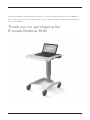
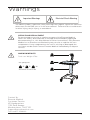
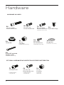
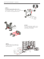
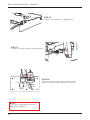
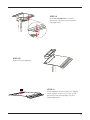
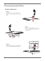
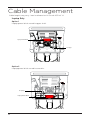
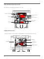
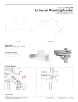
MANUAL 03.14.14
IM012-01
The Enovate Medical DUO Cart was designed to set a new standard in quality. Enovate Medical’s
goal is to provide a cart that is ready for years of use, and backed by a commitment of exemplary
service and support.
Thank you for purchasing the
Enovate Medical DUO
1
TABLE OF CONTENTS • MANUAL
1
WELCOME
3
WARNINGS
4
HARDWARE
5
TOOLS
7
CART FEATURES
9
GAS-SPRING CART ASSEMBLY
16
ACTUATOR CART ASSEMBLY
20
ACCESSORIES
CABLE MANAGEMENT
WARRANTY
2
Warnings
Important Warnings
Electrical Shock Warning
The above symbols represent safety warnings that require significant attention
when seen on the DUO cart or in the user manual. Failure to do so could result
in minor injury, major injury, or even death.
SERVICE AND REPLACEMENT
Do not attempt to service or replace any part of the Enovate Medical
DUO Cart unless directed to do so through Enovate Medical approved
documentation (i.e., this User Manual or other instructions). Only Enovate
Medical or an Enovate-certified entity may service or replace the cart
components. If any component on the cart is missing or damaged, the
cart must not be used. Contact Enovate Medical immediately to request
service.
MAXIMUM WEIGHTS
Total cart Weight:37lbs
B
Gas Spring Cart
A
+
B
+
A
C
=
Should not exceed 10 lbs
C
Total Cart Weight: 37lbs
Contact Us
Enovate Medical
Customer Service
US Headquarters
1152 Park Avenue
Murfreesboro, TN 37129
[email protected]
Toll free 877.258.8030
3
Hardware
HARDWARE INCLUDED
4x
4x
1/4 -20 x .75”
Socket Head Screw
1/4 -20 x 1.625”
Socket Head Screw
1x
4x
M6 x 1 x 25mm
Socket Head Screw Nylon Hole Plugs
Provided with actuator cart only
4x
4x
4x
Thumb Nut
1/4 -20”
Lock Nuts
Provided with LCD cart only
M4 x 16mm
Pan Head Screw
Provided with LCD cart only
1x
Flat Washer
Provided with actuator cart only
4x
8-32x.375” pan head
Phillips screws
Provided with actuator cart only
OPTIONAL HARDWARE INCLUDED FOR ACCESSORY INTEGRATION
2x
4x
4x
Provided with laptop
security bar only
Provided with laptop
security bar only
Provided with
LCD pole only
Security Screws
4
1/4 -20 x .75”
Button Head Screw
1/4 -20”
Lock Nuts
ench
Tools
TOOLS NEED FOR LCD INTEGRATION
Phillips Head
Screw Driver
7/16”
Socket
TOOLS INCLUDED
3/16”
Allen Wrench
3/32”
Allen Wrench
M4
Allen Wrench
OPTIONAL TOOLS NEEDED
FOR ACCESSORY INTEGRATION
1x
Security Bit
Provided with laptop
security bar only
5
IMPORTANT WARNINGS • MANUAL
Cart Features
40.5”
28.5”
FOOT PRINT
20 D X 18 W
SIT TO STAND
HEIGHT ADJUSTMENT
WORK SURFACE
22 w x 22.86 D
EXTERNAL STORAGE
18 ‘‘ w X 3.5 D X 3.5 H
6
MONITOR & TABLET
ADJUSTMENTS -10° to +90°
WORK SURFACE
23.5 w x 25.5 D
INTERNAL STORAGE
12.5 w X 8.25 D X 3 ” H
MONITOR & TABLET
ADJUSTMENTS 120°
IMPORTANT WARNINGS • MANUAL
Gas-spring Cart Assembly
STEP 1
Remove the box with the finger
holes which holds the assembly
components
STEP 2
Place the main box on its side
and slide out the second box
STEP 3
Remove top from the second box and
remove the column box.
STEP 4
Place the base upright and use the
assembly components box to assist
in attaching the column. Take care
to position the column in the proper
direction.
7
IMPORTANT WARNINGS • MANUAL
STEP 5
Use the (4) 1/4-20 x 1.625 screws
and 3/16" allen wrench to attach
the column to the base
STEP 6
Use the (4) 1/4-20 x.75 screws to
attach the internal storage shelf to
the column
NOTE:
If you are integrating a monitor
pole skip to page 16
STEP 7
Use the thumb nuts to attach
the work surface to the internal
storage shelf
STEP 8
Insert the storage bin
STEP 9
If the optional monitor pole or laptop
security bar accessory is not used
place the four hole plugs into the
mounting holes.
8
IMPORTANT WARNINGS • MANUAL
Actuator Cart Assembly
STEP 1
Remove the box with the finger
holes which holds the assembly
components
STEP 2
Place the main box on its side
and slide out the second box
STEP 3
Remove top from the second box and
remove the column box.
9
IMPORTANT WARNINGS • MANUAL
STEP 4
Place the base upright and use the
assembly components box to assist in
attaching the column. Take care to position
the column in the proper direction.
STEP 5
Use the (4) 1/4-20 x 1.625 screws
and 3/16" allen wrench to attach
the column to the base
STEP 6
Insert Actuator into column (as
shown), and line up "U" bracket
mounting holes.
10
IMPORTANT WARNINGS • MANUAL
STEP 7
Fasten Actuator "U" bracket with
1/4 - 20 X .500" socket cap screws
STEP 8
At opposite end, line up actuator
shaft with hole in top plate and
fasten M6 X 25 MM socket head
cap screw
STEP 9
Once actuator is connected, remove
outer 1/4-20 socket head cap screw and
loosen inner 1/4-20 socket head cap
screw enough to remove column clip
from assembly.
11
IMPORTANT WARNINGS • MANUAL
STEP 10
Retighten screw and discard column clip
STEP 11
Once Actuator is installed and secure,
connect the column and actuator wires
STEP 12
Install Actuator cover with 8 - 32 X
.375" phillips pan head screws.
12
IMPORTANT WARNINGS • MANUAL
STEP 13
Pull the column wire through the hole
in the shelf then use the (4) 1/4-20
x.75 screws to attach the internal
storage shelf to the column
STEP 14
Slide CHAC board into slot, as shown
STEP 15
Install battery charger and battery then
connect battery to charger, as shown
13
IMPORTANT WARNINGS • MANUAL
STEP 16
Install coil cord with 3 - gang outlet
STEP 17
Connect charger plug to 3-gang outlet
STEP 18
Connect cord from column, battery, and
pin housing to "CHAC" board, as shown
NOTE:
If you are integrating a monitor
pole skip to page 16
14
STEP 19
Use the thumb nuts to attach
the work surface to the internal
storage shelf.
STEP 20
Insert the storage bin.
STEP 21
If the optional monitor pole or laptop
security bar accessory is not used
place the four hole plugs into the
mounting holes.
15
Accessories
Monitor Integration
STEP 1
Remove work surface and attach
monitor pole using (4) 1/4- 20" lock
nuts.
STEP 2
Use the (4) Thumb Nuts to reattach
the work surface to the internal
storage shelf.
STEP 3
Attach the monitor to the VESA plate
using the M4x16 pan head screws.
16
IMPORTANT WARNINGS • MANUAL
Laptop Integration
Laptop Security Bar Configuration
Use this hole pattern for right
hand mousing placement
Use this hole pattern for
center placement
Use this hole pattern for left
hand mousing placement
STEP 1
Remove the work surface and attach
the laptop security system using the
hole pattern of your liking with (4)
1/4-20" lock nuts.
17
IMPORTANT WARNINGS • MANUAL
STEP 2
Use the Thumb Screws to reattach
the work surface to the internal
storage shelf.
STEP 3
Remove the security bar
using the speciality security
screwdriver bit provided.
STEP 4
Put laptop into place and
replace the security bar using
the security screws.
18
IMPORTANT WARNINGS • MANUAL
CPU Bracket Installation
Step 1
Place mounting bracket in place on
the column. Once in place attach
with (4) 6 x 1 x 12 screws.
Step 2
Attach back of CPU bracket to the mounting
bracket with (4) 1/4-20 X .5 screws.
Step 3
Attach bottom and front of CPU
bracket with thumb screws.
19
Cable Management
Cable lengths may very - interior dimension 12.5 w x 8.25 D x 3" H
Laptop Only
Option 1
Laptop power brick stored in upper shelf.
Laptop Power Brick
to Laptop
Option 2
Laptop power brick stored in outer bin.
to Laptop
Laptop Power Brick
20
Laptop with optional coil cord and 3 gang plug
Option 1
Laptop power brick stored in upper shelf plugged into optional 3 gang plug and
optional coil cord.
to Laptop
Optional Coil Cord
Optional 3 Gang Plug
Laptop Power Brick
Option 2
Laptop power brick stored in outer bin plugged into optional 3 gang plug and
optional coil cord.
Optional 3 Gang Plug
Optional Coil Cord
to Laptop
Laptop Power Brick
21
LCD with Small Form Factor PC
with optional 3 gang plug and optional coil cord.
Optional 3 Gang Plug
Small Form Factor PC
to Keyboard
to Mouse
Optional Coil Cord
VGA and Power
to Monitor
Power Brick
Laptop with actuator
Battery charger stored in upper shelf plugged into 3 gang plug and coil cord.
To Battery
Coil Cord
3 Gang Plug
Battery Charger
22
Warranty
WHAT'S COVERED AND HOW LONG?
Removing or damaging the serial number and barcode label will void all cart warranties
Standard warranty covers four (4) – years structural components, Warranty coverage begins on product’s
date of invoice. Standard warranty does not cover problems resulting from product abuse, negligence/accident,
misuse, improper operation, post-delivery physical damage, and/or product modifications without Enovate
Medical’s prior written approval. External peripherals (including: computing equipment/devices, monitors,
keyboards, mouse, USB hub, etc.) are not included in this warranty. Enovate Medical shall not be liable for any
consequential or incidental damages.
HOW WE HELP YOU
Support services provided along with the standard warranty must be requested within the expressed warranty
time frame for the product element. Technical support may request customer collaboration
and assistance during diagnosis to provide for next business day service as needed. Typically, this
requires, but is not limited to:
• Identifying a primary contact representative (with phone number and e-mail address) to work with Enovate
Medical and answer relevant questions. Providing the serial ID number and access to the product.
• Performing basic troubleshooting activities as directed by Enovate Medical’s Technical Support.
Resolution methods can include, but are not limited to, any of the following:
• Verbal/written instructions to correct the problem.
• Shipping of replacement parts OR a product swap.
• On-site dispatch of an Enovate Medical authorized service technician.
If needed, Enovate Medical will involve its design engineers or supplier partners for resolution assistance and
customer’s satisfaction. Determination for resolving warranty issues will be at Enovate Medical’s sole discretion.
TECHNICAL SUPPORT ASSISTANCE
Service requests can be made at any time via Enovate Medcial’s support website or by phone:
• www.enovatemedical.com/support
• 1-877-258-8030 toll-free
• Support Hours are Monday – Friday, 8 am to 5 pm EST (except holidays).
ENOVATE MEDICAL'S SERVICE PLEDGE
Our Customer Care team is located, supported, & operated by Enovate Medcial's employees in our US headquarters. A reply to all service requests, within two hours of their submittal during business hours. On-site Parts /
Service by the next business day as needed. Enovate Medical
Authorized Service Technicians are located at more than 400 locations across the United States.
CLEANING INSTRUCTIONS
• Use non abrasive cleaners or mild cleaning solutions. Do not use abrasive cleaners, solvents, polishes, waxes or steam cleaning tools.
• As a precaution to test the suitability of a cleaning product, apply to an inconspicuous area,
minimizing the time of exposure and the amount of cleaning agent (diluting as recommended by the supplier) in order to prevent any damage to the surface.
• Contamination by intensively colored substances, for example coffee, iodine, or dyes, have to be removed
immediately.
• Power System should be inspected bi-annually to ensure vent holes and pan guard are free of dust and debris
23
IMPORTANT WARNINGS • MANUAL
24
IMPORTANT WARNINGS • MANUAL
25
1152 Park Avenue
Murfreesboro, TN 37129
p. (888)909-8930 f. (615)896-8906
www.enovatemedical.com
[email protected]
©2013 Enovate Medical LLC. All Rights
Reserved