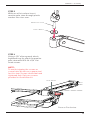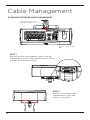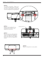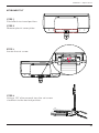
1
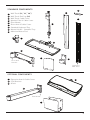
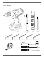
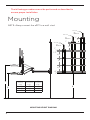
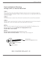
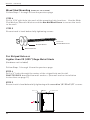
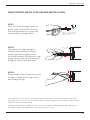
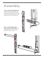
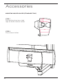
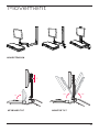
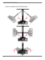
MANUAL 07.11.14
IM004-02
The Enovate Medical e997 Articulating Wall Arm was designed to set a new standard in quality. Enovate
Medical’s goal is to provide a wall arm that is ready for years of use, and backed by a commitment of
exemplary service and support.
Thank you for purchasing the
Enovate Medical e997 Articulating Wall Arm!
1
MANUAL • Warnings
2
1
WELCOME
3
WARNINGS
4
COMPONENTS & HARDWARE
8
MOUNTING
12
ASSEMBLY
16
CABLE MANAGEMENT
22
ADJUSTMENTS
26
ACCESSORIES
27
MOVEMENT
MANUAL • Table of Contents
Warnings
Important Warnings
Electrical Shock Warning
The above symbols represent safety warnings that require significant attention when seen
on the EMC cart or in the user manual. Failure to do so could result in minor injury, major
injury, or even death.
Read the entire installation manual before you begin.
MOUNTING
Installer must verify that the entire wall will safely support the combined weight of all attached
equipment and hardware. Improper installation of this product can cause extensive property damage or
serious personal injury, either during or after installation. It is the responsibility of the installer to ensure
that all applications including wood, concrete, block, brick, steel, etc are secured properly and are in
compliance with local and national building codes. California installations could require specific
anchorage, and additional mounting screws. Check with local authorities for codes in your area.
Other seismic states have similar regulations.
WARNING:
Because wall surfaces and construction methods and materials vary, it is imperative that
you consult with the appropriate engineering, architectural or construction professional to
ensure that your wall computing station is mounted properly to handle the applied loads.
ELECTRICAL SHOCK HAZARD:
Cutting or drilling into electrical wires and cables can cause FIRE, DEATH or SERIOUS
PERSONAL INJURY! Always make certain the area behind the mounting surfaces is free of
electrical wires and cables before drilling into wall.
EXPLOSION AND FIRE HAZARD:
Drilling into gas plumbing can cause EXPLOSION, FIRE, DEATH or SERIOUS PERSONAL
INJURY! Always make certain the area behind the mounting surface is free of gas, water,
waste, or any other plumbing before drilling into wall.
WARNING:
Weight should not exceed 20lbs
SERVICE AND REPLACEMENT
Warranty will be void if an attempt to service or replace any part of the Enovate Medical Wall Arm is made
unless directed to do so through Enovate Medical approved documentation (i.e., this User Manual or other
instructions). Only Enovate Medical or an Enovate-certified entity may service or replace the Enovate Medical Wall Arm components. If any component on the Enovate Medical Wall Arm is missing or damaged, the
wall station must not be used. Contact Enovate Medical immediately to request service.
If the unit is not working properly, please contact Enovate Medical Customer Service at:
enovatemedical.com/support
888.909.8930 toll free
3
Components &
Hardware
4
STANDARD COMPONENTS
1
2
3
4
5
6
7
8
9
2
3
Wall Track (32,” 42,“ 48”)
Wall Track End Cap (2x)
Wall Track Cable Cover
Monitor Pole & Cable Cover
Pivot Mount
Riser Arm & Cable Cover
Standard Keyboard Tray
Mouse Holder - Standard Tray
Adhesive Mouse Pad
1
4
8
7
6
9
Riser Arm
Knuckle
5
Bottom of
Wall Track
OPTIONAL COMPONENTS
10
11
12
Extension Arm & Cable Cover
CPU Bracket
eDesk
12
10
Pivot Mount
11
5
HARDWARE INCLUDED
(6-8)x
2x
1/4”-14 x 2 1/2”
Hex Nut Self Tapping Metal Screw
(for metal stud mounting only)
(6-8)x
(6-8)x
1/4 “x 1”
Phenolic Washer
1-4” x 1”
Wide Flat Washer
4x
4x
10-24 x 1/2”
Button Head Screw
4x
Dual Lock Pads
6
Plastic Washer
M4 x 16mm
Pan Head Screw
5x
Cable Tie
& Adhesive Pad
2x
10-24 x 3/4”
Flat Head Screw
4x
#10 x 1/4”
Standoff
TOOLS NEEDED
3/8” Socket
Wrench
Drill
5/64
Allen Wrench
1/8
Allen Wrench
4mm
Allen Wrench
3/16
Allen Wrench
Level
Pencil
5/16
Allen Wrench
1/2” Socket
Wrench
Phillips Screwdriver
Tape Measure
Flat Head Screwdriver
7
The following procedures must be performed as described to
ensure proper installation
Mounting
NOTE: Always mount the e997 to a wall stud.
Wall Stud
48”
Walltrack
Wall Stud
1"
42”
Walltrack
Wall Stud
32”
Walltrack
6"
1"
10"
1"
1.5"
8.5"
10"
8.5"
1.5"
1"
Y
X
Mounting
Height
Z
36.5"
32.5"
28.5"
Y
Max Keyboard
Height
45"
41"
37"
Z
Min Keyboard
Height
34"
30"
26"
MOUNTING HEIGHT DIAGRAM
8
Bottom of Track
X
MANUAL • Mounting
Preferred Method of Mounting
20 Gage (.035") or Heavier Metal Stud
STEP 1
D etermine Your desired keyboard height. Use the chart on previous page for
standard keyboard heights, adjust vertical dimensions as required for desired
keyboard height.
STEP 2
Locate the exact center line of the wall stud where the arm will be mounted.
STEP 3
Using a level, mark the hole locations for the appropriate track size using the
dimensions to the left (make note of the bottom of the track).
STEP 4
Place the track against the wall and secure with the Wide Flat Washer, the
Phenolic Washer and the Hex Nut Self Tapping Metal Screw
DO NOT DRILL PILOT HOLES.
STEP 5
Ensure track is level before fully tightening screws.
DO NOT OVER TIGHTEN SCREWS . If hole strips out see page 10.
1/4-14 x 2 1/2”
Hex Nut Self Tapping Metal Screw
Phenolic Washer
Wide Flat Washer
REF: OSHPD# OPA=2671-10
9
MANUAL • Mounting
Wood Stud Mounting (Hardware not included)
Follow Steps 1 through 3 from the previous page
STEP 4
Drill a 3/16" pilot hole into each of the mounting hole locations. Use the Wide
Flat Washer, Phenolic Washer and the Hex Nut Wood Screw to secure the track
to the wall.
STEP 5
Ensure track is level before fully tightening screws.
1/4-14 x 4”
Hex Nut Wood Screw
Phenolic Washer
Wide Flat Washer
For Striped Holes or
Lighter than 20 (.035") Gage Metal Studs
(Hardware not included)
Follow Steps 1 through 3 from the previous page
STEP 4
Drill a ½" holes through the center of the striped hole and install
SNAPTOGGLE® brand hollow wall anchors. (See wall anchor installation
instructions on page 11)
STEP 5
Ensure track is level before fully tightening with cross drive 1/4"-20 x 2 1/2" screws.
METAL STUD
Track
Wall
HOLLOW WALL
Metal Stud
Track
Wall
Wall Anchor
10
MANUAL •Mounting
SNAPTOGGLE® METAL STUD ANCHOR INSTALLATION
STEP 1 Drill a ½" hole through center of
metal stud. Hold metal channel
flat alongside plastic straps and
slide channel through hole.
1/2”
Must be 1-7/8” 1/2”
minimum
clearance behind wall for
channel rotation.
1/2”
Must be 1-7/8” minimum
3/8” - behind
3 5/8” wall for
clearance
channel Thick
rotation.
STEP 2
Hold ends of straps between
thumb and forefinger and pull
toward you until channel rests
flush behind wall. Slide plastic cap
along straps with other hand until
flange of cap is flush with wall.
Metal Stud
Must be 1-7/8” minimum
clearance behind wall for
Metal Stud
channel rotation.
3/8” - 3 5/8”
Thick
3/8” - 3 5/8”
Thick
Metal Stud
Metal Stud
Metal Stud
STEP 3
Metal Stud
nap straps at wall by pushing side
S
to side, snapping off straps level
with flange of cap.
Patented under one or more of the following U.S. Patent Nos.: 4,993,901; 5,028,186; 5,161,296;
5,938,385; 6,161,999; 7,144,212; 7,320,569; and foreign counterparts thereof and of 4,650,386 and
4,752,170. Other patents pending.
TOGGLER and typeface, symbol, TA, TB, TC, TH, ALLIGATOR, SNAPTOGGLE, and SnapSkru are
worldwide registered trademarks of Mechanical Plastics Corp.
11
Assembly
STEP 1 (NON-EXTENSION ARM)
Slide pivot mount to bottom of
wall track (you may need to pull
the pivot mount towards you while
sliding); level and secure screws
tightly with 3/16" allen wrench.
STEP 1.2 (EXTENSION ARM)
Slide pivot mount with extension
arm to bottom of wall track;
level and secure screws tightly
with 3/16" allen wrench.
12
MANUAL • Assembly
STEP 2
While on a flat surface insert
monitor pole stem through plastic
washer into riser arm.
Monitor Pole Stem
Plastic Washer
STEP 3
Using a 1/8" allen wrench attach
keyboard tray (or eDesk) to monitor
pole stem with #10-24 x 3/4" flat
head screws.
NOTE:
To avoid stripping the screws or
screw holes do not use a power tool
for this step. Screws should be hand
tightened only. Only use screws
provided in installation kit
Plastic Washer
Place on Flat Surface
13
MANUAL • Assembly
STEP 4 (NON-EXTENSION ARM)
Insert riser arm stem through
plastic washer into pivot mount,
and secure with large-slotted
pan head screw.
Riser Arm Stem
Plastic Washer
Large Slotted Pan Head Screw
STEP 4.2 (EXTENSION ARM)
Insert riser arm stem through
plastic washer into extension arm
and secure with large slotted pan
head screw.
Riser Arm Stem
Plastic Washer
Large Slotted Pan Head Screw
14
MANUAL • Assembly
MOUNTING THE MONITOR
STEP 1 Loosely insert two M4 x 16mm screws
with standoffs into the top two holes
of the VESA pattern on the back of the
monitor.
STEP 2 Align screws with the quick mount
slots in the monitor pole VESA plate.
Slide the monitor into place and
tighten the screws.
STEP 3 Insert the additional two M4 x 16mm
screws and standoffs into the bottom
two holes of the monitor pole VESA
plate to properly secure the monitor.
NOTE:
Use the 4 #10 Standoffs if needed.
Adhesive Mouse Pad
Place the adhesive mouse pad into
place before mounting the keyboard.
MOUNTING THE KEYBOARD
Mount keyboard to keyboard tray
using dual lock pads provided.
15
Cable Management
STANDARD KEYBOARD CABLE MANAGEMENT
Keyboard Tray Cable Notch
and Cable Management Insert
Adhesive Mouse Pad
STEP 1
Run the mouse and keyboard cables through
the keyboard notch letting them hang out of the
bottom of the keyboard tray.
STEP 2
Replace the rubber cable
management insert and
plastic cover plate.
16
MANUAL • Cable Management
eDESK CABLE MANAGEMENT
STEP 1
Extend keyboard tray.
STEP 2
Push the keyboard tray release
tabs to the right and remove the
keyboard tray.
STEP 3
Place adhesive pad with cable tie
into place as shown.
STEP 4
Lay the mouse and keyboard cables
into place and allow the ends of the
cables to hang out of the bottom of
the eDesk.
Cable Tie & Adhesive Pad
17
MANUAL • Cable Management
STEP 5
Tie cables into place. Take care
to leave the appropriate amount
of slack in the cables to open and
close the keyboard tray properly.
STEP 6
Replace the keyboard tray
and place the mouse and
keyboard into place.
Keyboard Tray Cable Notch
and Cable Management Insert
STEP 7
Run the mouse and keyboard
cables thought the keyboard
notch and replace the rubber
keyboard cable management
insert.
STEP 8
Replace the plastic cover plate.
18
MANUAL • Cable Management
RISER ARM CABLE MANAGEMENT
STEP 1
Run video and power cables
down monitor pole and riser
arm. Also run mouse and
keyboard cables into riser
arm. Snap cable covers into
place.
Monitor Pole
Cable Cover
Riser Arm
Cable Cover
Mouse Cable Exit
(Keyboard Cable Exit On Opposite Side)
Cable Tie & Adhesive Pad
STEP 2
Run cables along extension arm
(if applicable) and up wall track.
Snap cable cover into place.
Cable Tie & Adhesive Pad
Extension Arm
Cable Cover
19
MANUAL • Cable Management
STEP 3
Install wall track cover; place
a single side into place, then
starting at one end flex cover
inward until opposite side snaps
into place.
STEP 4 (WITHOUT CPU BRACKET)
Secure top plate with 10-24 x 1/2"
button head screws and a 1/8"
allen wrench.
20
MANUAL • Cable Management
STEP 4.2 (WITH CPU BRACKET)
Insert CPU bracket into wall track.
Top of wall track install.
Bottom of wall track install
Remove CPU bracket mount and replace
as shown.
CPU Bracket
STEP 5
Place CPU into CPU Bracket, adjust
front plate until it securely holds the
CPU, then tighten knobs.
CPU
21
Adjustments
RISER ARM VERTICAL TENSION ADJUSTMENT
Adjustments should be made only
after all peripherals are installed.
STEP 1
Ensure riser arm is parallel to the floor
STEP 2
Using 5/16" allen wrench adjust screw
clockwise or counterclockwise.
CLOCKWISE = LIGHTER TENSION
COUNTERCLOCKWISE = STRONGER TENSION
22
MANUAL • Adjustments
MONITOR POLE TENSION ADJUSTMENT
STEP 1
Remove plastic cover.
STEP 2
Using a 1/2" socket
wrench, adjust nut to
tighten or loosen tension.
CLOCKWISE = TIGHTEN TENSION
COUNTERCLOCKWISE = LOOSEN TENSION
23
MANUAL • Adjustments
WORK SURFACE AND MONITOR LEVELING
LEVEL
NOT LE
VEL
Movement when folded
Movement when extended
STEP 1
Lower riser arm to access set screws.
STEP 2
Using a 1/8" allen wrench loosen set screw
#1, this will unlock the adjustment pin.
STEP 3
Using a 4mm allen wrench tighten
or loosen set screw #2 to move
adjustment pin. Re-tighten set
screw #1.
Do not over tighten set screws.
24
1
2
MANUAL • Adjustments
KEYBOARD TILT
STEP 1
Fold eDesk to stored position.
STEP 2
Remove plastic cover plate.
STEP 3
Locate the set screw.
STEP 4
Using a 1/8” allen wrench turn the set screw
clockwise to the desired position.
25
Accessories
MOUNTING MOUSE HOLDER (STANDARD TRAY)
STEP 1
Peel backing from two-sided
tape on back of mouse holder.
STEP 2
Place mouse holder.
26
Movement
ARM EXTENSION
7"
90°
KEYBOARD TILT
22.5°
-22.5°
MONITOR TILT
27
MANUAL • Movement & Adjustment
RANGE OF MOVEMENT (WITH EXTENSION ARM)
900
28
900
900
900
900
900
MANUAL • Movement & Adjustment
RANGE OF MOVEMENT (NO EXTENSION ARM)
900
900
900
900
29
30
31
32
33
1152 Park Avenue
Murfreesboro, TN 37129
p. (888)909-8930 f. (615)896-8906
www.enovatemedical.com
[email protected]
©2013 Enovate Medical LLC. All Rights
Reserved