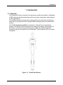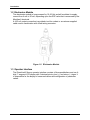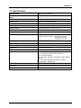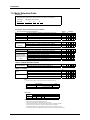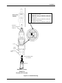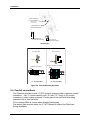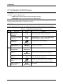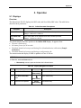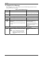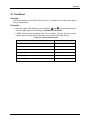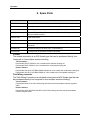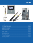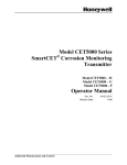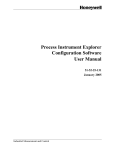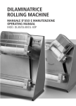
1
DirectLine® DL422 Sensor Module
for Meredian® II ORP Electrodes
User Manual
70-82-25-107
Rev. 2
1/03
Industrial Measurement and Control
Notices and Trademarks
Copyright 2003 by Honeywell
Revision 2 January 2003
Warranty/Remedy
Honeywell warrants goods of its manufacture as being free of defective materials and faulty
workmanship. Contact your local sales office for warranty information. If warranted goods are returned to
Honeywell during the period of coverage, Honeywell will repair or replace without charge those items it
finds defective. The foregoing is Buyer's sole remedy and is in lieu of all other warranties, expressed or
implied, including those of merchantability and fitness for a particular purpose. Specifications may
change without notice. The information we supply is believed to be accurate and reliable as of this
printing. However, we assume no responsibility for its use.
While we provide application assistance personally, through our literature and the Honeywell web site, it
is up to the customer to determine the suitability of the product in the application.
Industrial Measurement and Control
Honeywell
1100 Virginia Drive
Fort Washington, PA 19034
DirectLine is a registered trademark of Honeywell
Meredian is a U.S. registered trademark of Honeywell
Other brands or product names are trademarks of their respective owners
Insert 70-82-10-02 should accompany this document.
ii
DirectLine® DL422 Sensor Module User Manual
1/03
About This Document
Abstract
This manual contains all the information that is needed to install, configure, calibrate,
operate, and troubleshoot the DirectLine® Sensor. Insert 70-82-10-02, a quick reference
guide for configuring and calibrating the DL422, should accompany this document.
Contacts
World Wide Web
The following lists Honeywell’s World Wide Web sites that will be of interest to our
customers.
Honeywell Organization
WWW Address (URL)
Corporate
http://www.honeywell.com
Industrial Measurement and Control
http://www.honeywell.com/imc
International
http://www.honeywell.com/Business/global.asp
Telephone
Contact us by telephone at the numbers listed below.
Organization
United States and
Canada
Phone Number
Honeywell
1-800-423-9883
(215) 641-3610
Tech. Support
1-888-423-9883
Q&A Faxback
(TACFACS)
1-800-525-7439
Service
Symbol Definitions
The following table lists any symbols used in this document to denote certain conditions.
Symbol
Definition
Earth Ground. Functional earth connection. NOTE: This connection shall be bonded to
Protective earth at the source of supply in accordance with national and local electrical
code requirements.
1/03
DirectLine® DL422 Sensor Module User Manual
iii
Contents
1. INTRODUCTION .................................................................................................................... 1
1.1
1.2
1.3
1.4
1.5
Overview......................................................................................................................................... 1
Electronics Module ......................................................................................................................... 2
Operator Interface........................................................................................................................... 2
Specifications.................................................................................................................................. 3
Model Selection Guide ................................................................................................................... 4
2. INSTALLATION ..................................................................................................................... 5
2.1
2.2
2.3
2.4
Assembly and Wiring ...................................................................................................................... 5
Integral Mounting ............................................................................................................................ 7
Remote Mounting ........................................................................................................................... 8
Conduit connections ..................................................................................................................... 10
3. CONFIGURATION ............................................................................................................... 11
3.1
3.2
Overview....................................................................................................................................... 11
Configuration Set Up Procedure................................................................................................... 12
4. CALIBRATION..................................................................................................................... 14
4.1
4.2
4.3
Calibration Diagnostics................................................................................................................. 14
Calibration Diagnostic Reset ........................................................................................................ 14
Calibration..................................................................................................................................... 14
5. OPERATION ........................................................................................................................ 17
5.1
5.2
5.3
Displays ........................................................................................................................................ 17
Diagnostic Error Messages .......................................................................................................... 18
Unit Reset ..................................................................................................................................... 19
6. SPARE PARTS .................................................................................................................... 20
7. SALES AND SERVICE ........................................................................................................ 21
iv
DirectLine® DL422 Sensor Module User Manual
1/03
Tables
Table 2-1 Assembly and Wiring Procedure for Field Wiring Connector___________________________ 6
Table 2-2 Integral Mounting Procedure for ORP Electrodes __________________________________ 7
Table 2-3 Remote Mounting Procedure for ORP Electrodes__________________________________ 8
Table 3-1 Configuration Set Up Procedure ______________________________________________ 12
Table 4-1 Oxidation-Reduction Potential of Reference Solutions at Specified Temperature_________ 15
Table 4-2 Zero (Standardization) Calibration Procedure ____________________________________ 16
Table 5-1 Online Parameter Descriptions _______________________________________________ 17
Table 5-2 Display Navigation Procedure ________________________________________________ 17
Table 5-3 Online Diagnostic Errors ____________________________________________________ 18
Table 5-4 Factory Default Values _____________________________________________________ 19
1/03
DirectLine® DL422 Sensor Module User Manual
v
Figures
Figure 1-1 DirectLine® Sensor ________________________________________________________ 1
Figure 1-2 Electronics Module _________________________________________________________ 2
Figure 2-1 Cordset Connection and Wiring ________________________________________________ 5
Figure 2-2 Field Wiring Connector ______________________________________________________ 6
Figure 2-3 Integral Mounting __________________________________________________________ 7
Figure 2-4 Remote Mounting __________________________________________________________ 9
Figure 2-5 Remote Mounting Hardware_________________________________________________ 10
vi
DirectLine® DL422 Sensor Module User Manual
1/03
Introduction
1. Introduction
1.1 Overview
The DirectLine® Sensor consists of an electronics module connected to a Meredian
II ORP electrode that eliminates the need for pre-amps, transmitters, and analyzers
in ORP applications.
The modular electronics design can be separated from the electrode, allowing the
electrode to be easily removed or replaced while retaining power to the electronics
module.
The DL422 electronics module is contained in a Nema Type 4x polysulfone
housing. The Module can be mounted as an integral unit directly connected to the
electrode or remotely using an electrode with a cable. The sealed polysulfone
housing has plug-in connections for the Meridian II ORP probe and 4-20 mA output
connection.
Figure 1-1 DirectLine® Sensor
1/03
DirectLine® DL422 Sensor Module User Manual
1
Introduction
1.2 Electronics Module
The electronics module is loop-powered by 16-42 Vdc and will modulate its supply
current from 4 mA to 20 mA, depending upon the ORP value that is measured by the
Meridian II electrode.
A 4-20 mA output connection is provided via a 6m cordset or a customer supplied
cable used in combination with a field wiring connector.
Figure 1-2 Electronics Module
1.3 Operator Interface
The DirectLine® Sensor operator interface consists of three pushbuttons and one 4digit, 7-segment LCD display with 3 decimal points, plus (+), and minus (–) signs. It
is responsible for the display of measured values and configuration of parameter
values.
2
DirectLine® DL422 Sensor Module User Manual
1/03
Introduction
1.4 Specifications
Displayed ORP
–1600 mV to +1600 mV
Meredian Sensor Survivable Temperature
Range
–10 °C to +130 °C (14 °F to 266 °F)
Electronics Module Ambient Temperature
–20 °C to +85 °C (–4 °F to +185 °F)
Output Type
4-20 mA (2-wire loop powered)
Output Scale
–1600 mV to +1600 mV
Output Calibration
4-20 mA
Output Cordset
Shielded twisted pair, length 6 m (19.7’)
User Termination
Tinned leads
Sensor Cable Length
3.65 m (12’) or 6.096 m (20’)
Power
16-42 Vdc
Maximum load resistance:
250 ohms at 16 Vdc
600 ohms at 24 Vdc
1400 ohms at 42 Vdc
Local Display and Buttons
LCD 4-digit, 7-segment
Engineering Units
mV
Calibration Options
1 point Sample
Diagnostics
Sensor and electronics
Case
Weatherproof, corrosion-resistant plastic housing
Approvals
CE Mark for Industrial Applications
UL – General Purpose for Process Control
CSA – General Purpose
FM – CLI, DIV1, Groups C & D and CLI, Zone 0 AEx ia
IIB (IS)
FM – CLI, DIV2, Groups C & D and CLI, Zone 2,
Groups IIB (N.I. Field Wiring)
Remote Mounting
Pipe, Wall, or DIN Rail
Dimensions
H 123 mm (4.84”) x W 48 mm (1.89”) x D 46 mm (1.81”)
Weight
Approximately 142 g (5.0 oz.)
1/03
DirectLine® DL422 Sensor Module User Manual
3
Introduction
1.5 Model Selection Guide
Instructions
Select the desired key number. The arrow to the right marks the selection available.
Make the desired selections from Tables I through IV using the column below the
proper arrow.
A dot ( ) denotes availability.
Key Number
_____
I
-
_
II
-
_
-
III
_
IV
-
____
Key Number - DirectLine®Sensor Electronics Module
(Specify electrodes/cells/probes separately)
pH
For use with Durafet II, Meredian II & HPW7000 pH electrodes
ORP
For use with ORP electrode.
Conductivity
For use with Contacting Conductivity Cells
DO - PPM
For use with Dissolved Oxygen ppm Probes
For use with Dissolved Oxygen ppb Probes
DO - PPB
Selection
Availability
DL421
DL422
DL423
DL424
DL425
TABLE I - OUTPUT CABLE
Output Cable for None (replacement module or customer supplied output cable)-Note 1
Integral or Remote Cordset - 6m (19.7 ft.) - includes connector and cable - Note 2
Field Wiring Connector only - customer supplies cable only-Note 2
Mounting
D
E
F
TABLE II - SENSOR CABLE/REMOTE CONNECTOR (between electronic module and electrode, sensor or pro
Integral Mounting
No cable or connector required
Remote Mounting Cable 6,096m (20 ft.) of sensor cable - Durafet II Remote Mounting
- Durafet only
15,24m (50 ft.) of sensor cable - Durafet II Remote Mounting
Remote Mounting Connector - Meredian II pH
Remote Mounting
Remote Mounting Connector - Meredian II ORP
Connector (Cable is
Remote Mounting Connector - HPW7000
supplied with sensor or
Remote Mounting Connector - Conductivity
probe)
Remote Mounting Connector - Dissolved Oxygen
0
1
2
3
3
4
5
6
d
e
e
e
d
d
d
d
e
e
e
e
e
TABLE III - REMOTE MOUNTING OPTIONS
Mounting Kit for
Remote Mounting
None Integral unit - mounting not required
2" (5,08 cm) Pipe mtg. bracket, wall mtg, & DIN Rail clip
A
B
TABLE IV - OPTIONS
Tagging
Certificates
None
Linen Customer ID Tag - 3 lines w/22 characters/line
SS Customer ID Tag - 3 lines w/22 character/line
None
Calibration & Conformance
00 _ _
LT _ _
SS _ _
_ _ 00
_ _ CC
Notes:
1 Customer supplies cordset or cable with M12 connecter. Suppliers & P/Ns include:
Cord--set
M12 Field Wiring Connector
Cable
Turck
Phoenix Contact
SAC-3P-5.0-PUR/M12FSSH Stainless
RKV4T-6/S618
SACC-M12FS-4CON-PG7
B8141-0
2-wire twisted shielded pair
2 Recommended cable is 2-wire twisted shielded pair
RESTRICTIONS
Restriction
Letters
d
e
Available Only With
Selection
Table
IIl
A
III
B
Table
Not Available With
Selection
ORDERING INSTRUCTIONS:
1. Part numbers are provided to facilitate Distributor Stock.
2. Orders may be placed either by model selection or by part number.
3. Part numbers are shown within the model selection tables to assist with compatibility information.
4. Orders placed by model selection are systematically protected against incompatibility.
5. Compatibility assessment is the responsibility of the purchaser for orders placed by part number.
6. Items labeled as N/A are not available via the stocking program and must be ordered by model selection.
4
DirectLine® DL422 Sensor Module User Manual
1/03
Installation
2. Installation
2.1 Assembly and Wiring
Depending on the customer selected output cable options, the DirectLine can be
wired to an appropriate 16-42 Vdc source using 2 different methods:
1) Cordset. See Figure 2-1.
2) Field wiring connector with customer supplied cable. See page 6.
2.1.1 Cordset
Power Supply
Minimum: 16 V @ 250 ohms (max.)
Maximum: 42 V @ 1400 ohms (max.)
_
+
_
Chart Recorder, Load
Controller, etc.
Resistance
(Use 250 ohms +
for 1-5 V signal)
Black (–)
Shield
Wire
(Ground)
Brown (+)
Cordset 6m (19.7’)
*
*Blue wire not used
Electronics
Module
Figure 2-1 Cordset Connection and Wiring
1/03
DirectLine® DL422 Sensor Module User Manual
5
Installation
2.1.2 Field Wiring Connector with customer supplied cable
Refer to Figure 2-2. The field wiring connector supports customer supplied cable with an
outer diameter of 4-6mm, 2-wire twisted shielded pair.
Table 2-1 Assembly and Wiring Procedure for Field Wiring Connector
Step
Procedure
1
Disassemble field wiring connector
a) Unscrew parts to separate pressure screw, clamp type cage, gasket,
housing and female insert.
2
Insert customer supplied cable through connector parts
a) Slide pressure screw over skin and tinned customer cable (note
orientation).
b) Slide clamp type cage over cable (note orientation).
c) Slide gasket over cable.
d) Slide housing over cable (note orientation).
3
Connect wires to pins
Look closely at end of female insert to locate pin numbers. Connect
positive wire to pin 1 and negative wire to pin 4. Remaining wires and
female insert pins 2 and 3 are unused.
4
Assemble field wiring connector
a) Screw female insert to housing until female insert’s o-ring is
compressed.
b) Slide clamp type cage/gasket into housing.
c) Thread pressure screw into housing until ¼ turn past finger tight.
5
Connect cable to power supply
Wire the other end of the Output cable to a 16-42 Vdc source as indicated
in Figure 2-1. Note: your wire colors may be different.
To Power Supply
Pressure screw
Clamp-type cage
Gasket
Pos +
Output cable
(Customer supplied)
Neg Housing
Female insert with 4
numbered pins
Figure 2-2 Field Wiring Connector
6
DirectLine® DL422 Sensor Module User Manual
1/03
Installation
2.2 Integral Mounting
Table 2-2 Integral Mounting Procedure for ORP Electrodes
Step
Procedure
Connect Electrode to Pipe and Electronics Assembly (Figure 2-3)
1
Screw the electrode into the pipe tee (3/4 “ NPT thread).
Make sure that the final position of the installed electronics module allows the display to
be easily viewed by plant personnel.
2
Align the slots in the electronics module with those in the electrode and press down to
connect the electronics to the electrode.
3
Tighten the locking screw on the bottom rear of the electronics module.
Electronics
Module
Step 2
Step 3
Locking Screw in
Rear of Housing
Step 4
Electrode
Step 1
Figure 2-3 Integral Mounting
1/03
DirectLine® DL422 Sensor Module User Manual
7
Installation
2.3 Remote Mounting
When the DL422 is specified with Table II = 3, the Remote Connector Assembly (part number
51500768-002) is supplied loose for connection of the Meredian II ORP electrode cable to the
DL422 module. Table 2-3 gives the mounting procedure.
Table 2-3 Remote Mounting Procedure for ORP Electrodes
Step
Procedure (Refer to Figure 2-4 and Figure 2-5)
1
Turning counterclockwise, remove strain relief/cover combination from the remote
connector assembly.
2
Loosen and remove compression cap from strain relief fitting. Carefully push cable end
through cap and strain relief fitting so that these parts are strung back along cable
jacket.
3
Connect cable leads as follows:
Terminal 1 =
Terminal 2 =
Terminal 3 =
Terminal 4 =
Terminal 5 =
Terminal 6 =
8
Black Reference Lead
100K ohm resistor (pre-installed by Honeywell)
100K ohm resistor (pre-installed by Honeywell)
Shield
1 Megohm resistor (pre-installed by Honeywell)
Red Measuring Lead and
1 Megohm resistor (pre-installed by Honeywell)
4
Slide cover along cable and tighten by hand onto the remote connector assembly.
5
Slide cap along cable and tighten onto cable jacket with small wrench until cable cannot
slide within strain relief rubber bushing.
6
Remove red protective vinyl boot from opposite end of connector assembly.
7
Apply a thin film of silicon grease on the ID of the electronics module’s electrode
mounting cavity.
8
Plug remote connector assembly into DL422 module aligning polarity tab of module
housing and mating groove on connector.
DirectLine® DL422 Sensor Module User Manual
1/03
Installation
1
2
3
4
5
6
Electronics
Module
Black Reference Lead
100K-ohm resistor (pre-installed by Honeywell)
100K-ohm resistor (pre-installed by Honeywell)
Shield Lead
1 Megohm resistor (pre-installed by Honeywell)
Red Measuring Lead and
1 Megohm resistor (pre-installed by Honeywell)
Protective
yellow vinyl sleeve
(remove)
Cover
Strain
Relief
Compression
Cap
Remote Wiring Cable
12 or 20 Feet
Electrode
Remote Electronics
Module for
Meredian II Electrodes
Figure 2-4 Remote Mounting
1/03
DirectLine® DL422 Sensor Module User Manual
9
Installation
Hose Clamp Slot
for Pipe Mounting
(Hose Clamp
included in kit)
Through Hole for
DIN Rail Mounting
Metal clip for
“U” DIN rail mounting
Gray clip for
“G” DIN rail mounting
Mounting Kit
View from End
View from End
Panel
Panel
Terminal Connectors
Barriers, Repeater, Isolators
Front View
Front View
“U” Style DIN Rail
“G” Style DIN Rail
Figure 2-5 Remote Mounting Hardware
2.4 Conduit connections
The DirectLine provides a male ½” NPT thread to accommodate a customer conduit
connection. Use ½” conduit coupling (min. 38.1mm (1.5”) long) on DL conduit
connection to clear cordset connector. Conduit can not be used with field wiring
connector due to size restriction.
Do not exceed 200in-lb. torque when attaching fixed piping.
Use wrench flats provided under the ½” NPT threads to support the DirectLine
during installation.
10
DirectLine® DL422 Sensor Module User Manual
1/03
Configuration
3. Configuration
3.1 Overview
Configuration Parameters
Set Up consists of configuring the following functions:
•
Noise Suppression Frequency Selection – Selection of 50 Hz or 60 Hz.
Defaults to 60 Hz at unit reset.
•
Output Configuration – The following Output Configuration functions can be
selected:
0 % Range
0 % Range values can be adjusted within a range of
–1600 mV to +1600 mV in 10 mV increments.
100 % Range
100 % Range values can be adjusted within a range of
–1600 mV to +1600 mV in 10 mV increments.
0 % Calibration
Output current can be typically adjusted to within a range
of 3.80 mA to 4.40 mA.
100 % Calibration
Output current can be typically adjusted to within a range
of 19.60 mA to 20.40 mA.
Table 3-1 provides steps and entry information for the complete configuration sequence.
1/03
DirectLine® DL422 Sensor Module User Manual
11
Configuration
3.2 Configuration Set Up Procedure
ATTENTION:
In Table 3-1, under the Press column:
• Hold means to hold the button down until the display changes.
• Momentarily means to press and release the indicated button.
From the Online ORP display, follow this procedure.
ATTENTION:
If no key is pressed for 60 seconds, the display will abort the entry mode and default to Online Display.
Table 3-1 Configuration Set Up Procedure
Step
1
Operation
Press
Enter Noise
Suppression
Frequency
MODE
Hold
nSUP (for 1 second) then,
(Noise Suppression Frequency Selection)
Edit Noise Suppression
Frequency
MODE
Hold
Flashing Display – You are now in EDIT mode
(Value of current Frequency selection)
To select 50 Hz or 60 Hz (default)
Select desired
Frequency
2
Momentarily
Save the Noise
Suppression Frequency
MODE
Momentarily
Selection for frequency
Enter Output
Configuration
MODE
Momentarily
OutC Enter Output Calibration
0 % Range Value
Selection
Momentarily
Edit 0 % Range Value
Selection
Select desired 0 % ORP
Value
Save the New 0 %
Range Value
12
Display
MODE
Hold
rnGL (for 1 second) then,
(value of current 0 % Range Value Selection)
Flashing Display – You are now in EDIT mode
Value of current 0 % selection)
Selected 0 % ORP Value in 10 mV increments
Momentarily
Range: –1600 to +1600 mV (default –1600 mV)
MODE
Momentarily
(New Value)
DirectLine® DL422 Sensor Module User Manual
1/03
Configuration
Step
3
Operation
Press
100 % Range Value
Selection
Momentarily
Edit 100 % Range Value
Selection
rnGH (for 1 second) then,
(value of current 100 % Range Value Selection)
Flashing Display – You are now in EDIT mode
(value of current 100 % selection)
Selected 100 % ORP Value in 10 mV increments
Select 100 % ORP
Value
Save the New 100 %
Range Value
4
MODE
Hold
Display
Momentarily
Range: –1600 to +1600 mV (default 1600 mV)
MODE
Momentarily
(New Value)
0 % Calibration
AdJL
Momentarily
Adjust 0 % Calibration
MODE
Hold
AdJL (flashes) – You are now in EDIT mode
Range: 3.80 to 4.40 mA typically (default 4.00 mA)
+AdJL (increments value)
−AdJL (decrements value)
Momentarily
Save 0 % Calibration
5
MODE
Momentarily
100 % Calibration
AdJL
AdJH
Momentarily
Adjust 100 %
Calibration
MODE
Hold
AdJH (flashes) – You are now in EDIT mode
Range: 19.60 to 20.40 mA typically
(default 20.00 mA)
+AdJH (increments value)
−AdJH (decrements value)
Momentarily
6
1/03
Save 100 % Calibration
MODE
Momentarily
AdJH
Return to Online Display
MODE
Momentarily
Returns to Online Display
DirectLine® DL422 Sensor Module User Manual
13
Calibration
4. Calibration
4.1 Calibration Diagnostics
Introduction
The manual standardization adjustment changes the zero offset diagnostics used by this
system. This value is viewed as read-only information. It is good practice to observe this
value after calibration. Monitoring the value over time will help you predict when the
electrode will need to be replaced.
Zero Offset Value
When Online ORP value is displayed, PRESS 1 button momentarily to display the current
Zero Offset value.
Zero Offset is non-volatile and is initialized to 0 mV at unit reset.
It has a range of ± 120 mV and it is updated after each calibration.
60 Second Timeout
If no key is pressed for 60 seconds, the display will abort the entry mode and default to Online
Display.
4.2 Calibration Diagnostic Reset
Introduction
When a new electrode is installed, the indicated ORP will use the zero offset value from the
previous calibration. Depending on the condition of the replaced electrode, the difference
between the known and indicated ORP of the new electrode may vary as much as several
millivolts. A calibration on the new electrode will correct this difference.
Zero Offset ORP Value
a) Momentarily press 1 to view the Zero Offset value. From this display press and hold
the 1 button until the Zero Offset ORP value resets to factory default “0”.
b) Press MODE button, or wait 60 seconds, to return to Online ORP.
4.3 Calibration
Overview
Calibration consists of the following function:
• Calibrating the Zero (Standardization) – Manual ORP calibration. In manual
calibration, you can select a new ORP value above or below the recognized live ORP
value.
14
DirectLine® DL422 Sensor Module User Manual
1/03
Calibration
ORP Calibration Using Reference Solution
Recommended to adjust for changes in electrode potential over time
An ORP measuring system can be checked by measuring a solution having a known
oxidation-reduction potential, then adjusting the sensor to match. Although a reference
solution provides only an approximation of ORP potential, the system can be adjusted
periodically to compensate for changes in electrode potential over time.
Materials
The materials required to use the ORP standardization method are:
•
A solution with a known oxidation-reduction potential. (See “Instructions for
preparing solution” below.)
•
A container for the solution, large enough to immerse the electrode to measuring
depth.
•
Distilled or de-ionized water to rinse the electrode.
Instructions for preparing solution
To prepare an ORP standardization solution, dissolve 0.1 g of quinhydrone powder (available
as Honeywell part number 31103015 for a 2 oz. bottle) in 5 cc of acetone or methyl alcohol
(methanol). Add this to not more than 500 cc of a standard pH reference solution (buffer),
about 1 part saturated quinhydrone to 100 parts buffer solution. The oxidation potential of
this solution is listed below for several temperatures. The polarity sign shown is that of the
measuring element with respect to the reference element.
These solutions are unstable and should be used within eight hours of preparation.
All mV values in Table 4-1 have a ± 30 mV tolerance.
Table 4-1 Oxidation-Reduction Potential of Reference Solutions at Specified Temperature
pH Buffer Solution
(Honeywell Part Number)
1/03
Temperature
20 °C
25 °C
30 °C
4.01 @ 25 °C (31103001)
267 mV
263 mV
259 mV
6.86 @ 25 °C (31103002)
100 mV
94 mV
88 mV
7.00 @ 25 °C (not available from Honeywell)
92 mV
86 mV
80 mV
9.00 @ 25 °C (not available from Honeywell)
–26 mV
–32 mV
–39 mV
9.18 @ 25 °C (31103003)
–36 mV
–43 mV
–49 mV
DirectLine® DL422 Sensor Module User Manual
15
Calibration
Calibration Procedures
ATTENTION:
In Table 4-2, under the Press column:
• Hold means to hold the button down until the display changes.
• Momentarily means to press and release the indicated button.
Table 4-2 Zero (Standardization) Calibration Procedure
Step
1
2
Operation
Press
Enter Zero
(Standardization)
Calibration
1
CAL1
Hold
Do Sample (Manual)
Calibration
Edit ORP Value
Display
1
Momentarily
or
SCAL for one second,
then displays Live ORP Value.
To edit ORP Value (Flashing Display)
Momentarily
Save New ORP
Value
16
MODE
Momentarily
ORP Value is saved and goes to Online Display.
DirectLine® DL422 Sensor Module User Manual
1/03
Operation
5. Operation
5.1 Displays
Overview
The DirectLine® DL422 displays the ORP value and Zero Offset ORP value. The table below
describes these parameters.
Table 5-1 Online Parameter Descriptions
Parameter
Description
Online ORP
Measured ORP expressed with fixed whole number precision.
Range: –1600 mV to +1600 mV
Zero Offset ORP
Value
Zero Offset ORP value expressed with whole number precision.
Range: −120 mV to +120 mV
The default display and home position is the Online ORP display. It appears when:
The unit is powered up
No button presses for 60 seconds
The Mode button has been pressed during Zero (Standardization) calibration (Sample
Calibration)
The Mode button has been pressed during a configuration edit
The measurement and display of ORP is updated at a rate of 500 ms.
ATTENTION:
In Table 5-2, under the Press column:
• Momentarily means to press and release the indicated button.
Table 5-2 Display Navigation Procedure
Step
Operation
Press
1
View Online ORP value
2
View Zero Offset ORP
value
3
1/03
Return to home position
MODE
Momentarily
Display
(measured ORP)
(Zero Offset ORP)
Momentarily
MODE
Momentarily
(measured ORP)
DirectLine® DL422 Sensor Module User Manual
17
Operation
5.2 Diagnostic Error Messages
When a diagnostic error or status condition occurs, the Online Display alternates between
measured ORP and a text message.
Table 5-3 Online Diagnostic Errors
What you see
CNFG
What it is
Data error detected.
What to do
Reset unit or cycle power.
Second occurrence will show FALT.
FALT
Unit electronics are defective.
Replace electronics module.
These errors may occur when online ORP is displayed.
O HI
Measured ORP is > 1600 mV
Bring process within limits
O LO
Measured ORP is < –1600 mV
Bring process within limits
PRBE
Probe is defective, removed from process, or not
connected.
Check probe, connection and
presence of sample.
Forces the output to burnout level (approximately
21.8 mA).
When the source of the error is
removed, the error will clear and the
output will return to normal
operation.
This error may occur during probe calibration and abort the calibration process.
FAIL
This error message is preceded by the message
“FAIL”
Press Mode to return to online
display.
ZRNG The Zero (Standardization) calibration
failed due to a calculated Zero Offset
value outside the range of –120 mV to
+120 mV.
18
DirectLine® DL422 Sensor Module User Manual
1/03
Operation
5.3 Unit Reset
Overview
Unit Reset initializes all of the DirectLine® Sensor’s calibration and configuration data to
factory default values.
Procedure
• From the Online ORP display, press and hold the 1 and 2 buttons simultaneously
until the “rSEt” appears on the display (minimum of 10 seconds).
• “rSEt” will remain on the display until reset is complete. Next, the firmware version
number appears briefly and the unit then returns to the Online ORP display.
Table 5-4 Factory Default Values
Data
1/03
Default Values
Zero Offset
0 mV
Noise Suppression Frequency Selection
60 Hz
Output Configuration – 0 % Range Value
–1600 mV
Output Configuration – 100 % Range Value
1600 mV
Output Configuration – 0 % Calibration
4.00 mA typically
Output Configuration – 100 % Calibration
20.00 mA typically
DirectLine® DL422 Sensor Module User Manual
19
Operation
6. Spare Parts
Part Number
Description
51452682-001
DirectLine® Sensor Module (Replacement Module)
51452683-001
6m cordset
51452684-001
Field Wiring Connector supports customer supplied cable (4-6 mm OD)
51500768-002
Remote Electrode Cable Connector Assembly– Includes O-rings, strain relief,
and pre-installed resistors
51451371-001
Cable Strain Relief
51198302-006
Internal O-ring for Remote Electrode Cable Connector
31086221
External O-ring for Integral Meredian Electrode or Remote Electrode Cable
Connector
51452655-001
Remote Mounting Kit for Wall, Pipe, or DIN Mounting
51452706-001
Locking screw (locks sensor module to electrode)
Cordset
The cordset connection is an M12 female type that can be purchased directly from
Honeywell or from multiple vendors including:
Turck Industries
Part Number RKV4T-6/S618 for a 6 m cordset with a stainless coupling nut
Part Number RK4T-6/S618 for a 6 m cordset with a nickel plated coupling nut
Phoenix Contact
Part Number SAC-3P-5.0-PUR/M12FSSH Stainless for a 5m cordset with a stainless coupling nut
Part Number SAC-3P-5.0-PUR/M12FSSH for a 5m cordset with a nickel plated coupling nut
Field Wiring connector
The Field Wiring Connector is an all-plastic screw terminal M12 female type that can
be purchased directly from Honeywell or from multiple vendors including:
Turck Industries
Part Number B8141-0 for a M12 field wiring connector that accommodates customer supplied
cable.
Phoenix Contact
Part Number SACC-M12FS-4CON-PG7 for a M12 field wiring connector that accommodates
customer supplied cable.
20
DirectLine® DL422 Sensor Module User Manual
1/03
7. Sales and Service
For application assistance, current specifications, pricing, or name of the nearest Authorized Distributor,
contact one of the offices below.
ARGENTINA
HONEYWELL S.A.I.C.
BELGRANO 1156
BUENOS AIRES
ARGENTINA
Tel. : 54 1 383 9290
ASIA PACIFIC
HONEYWELL ASIA
PACIFIC Inc.
Room 3213-3225
Sun Kung Kai Centre
N° 30 Harbour Road
WANCHAI
HONG KONG
Tel. : 852 829 82 98
AUSTRALIA
HONEYWELL LIMITED
5 Thomas Holt Drive
North Ryde Sydney
NSW AUSTRALIA 2113
Tel. : 61 2 353 7000
AUSTRIA
HONEYWELL AUSTRIA
G.m.b.H.
Handelskai 388
A1020 VIENNA
AUSTRIA
Tel. : 43 1 727 800
BELGIUM
HONEYWELL S.A.
3 Avenue de Bourget
B-1140 BRUSSELS
BELGIUM
Tel. : 32 2 728 27 11
BRAZIL
HONEYWELL DO
BRAZIL
AND CIA
Rua Jose Alves Da
Chunha
Lima 172
BUTANTA
05360.050 SAO PAULO
SP
BRAZIL
Tel. : 55 11 819 3755
BULGARIA
HONEYWELL EOOD
14, Iskarsko Chausse
POB 79
BG- 1592 Sofia
BULGARIA
Tel : 359-791512/
794027/ 792198
1/03
CANADA
HONEYWELL LIMITED
THE HONEYWELL
CENTRE
300 Yorkland Blvd.
NORTH YORK,
ONTARIO
M2J 1S1
CANADA
Tel.: 800 461 0013
Fax:: 416 502 5001
CZECH
REPUBLIC
HONEYWELL, Spol.s.r.o.
Budejovicka 1
140 21 Prague 4
Czech Republic
Tel. : 42 2 6112 3434
DENMARK
HONEYWELL A/S
Automatikvej 1
DK 2860 Soeborg
DENMARK
Tel. : 45 39 55 56 58
FINLAND
HONEYWELL OY
Ruukintie 8
FIN-02320 ESPOO 32
FINLAND
Tel. : 358 0 3480101
FRANCE
HONEYWELL S.A.
Bâtiment « le Mercury »
Parc Technologique de St
Aubin
Route de l’Orme
(CD 128)
91190 SAINT-AUBIN
FRANCE
Tel. from France:
01 60 19 80 00
From other countries:
33 1 60 19 80 00
GERMANY
HONEYWELL AG
Kaiserleistrasse 39
D-63067 OFFENBACH
GERMANY
Tel. : 49 69 80 64444
HUNGARY
HONEYWELL Kft
Gogol u 13
H-1133 BUDAPEST
HUNGARY
Tel. : 36 1 451 43 00
ICELAND
HONEYWELL
Hataekni .hf
Armuli 26
PO Box 8336
128 reykjavik
Iceland
Tel : 354 588 5000
ITALY
HONEYWELL S.p.A.
Via P. Gobetti, 2/b
20063 Cernusco Sul
Naviglio
ITALY
Tel. : 39 02 92146 1
MEXICO
HONEYWELL S.A. DE
CV
AV. CONSTITUYENTES
900
COL. LOMAS ALTAS
11950 MEXICO CITY
MEXICO
Tel : 52 5 259 1966
THE NETHERLANDS
HONEYWELL BV
Laaderhoogtweg 18
1101 EA AMSTERDAM
ZO
THE NETHERLANDS
Tel : 31 20 56 56 911
NORWAY
HONEYWELL A/S
Askerveien 61
PO Box 263
N-1371 ASKER
NORWAY
Tel. : 47 66 76 20 00
POLAND
HONEYWELL Sp.z.o.o
UI Domainewksa 41
02-672 WARSAW
POLAND
Tel. : 48 22 606 09 00
PORTUGAL
HONEYWELL
PORTUGAL LDA
Edificio Suecia II
Av. do Forte nr 3 - Piso 3
2795 CARNAXIDE
PORTUGAL
Tel. : 351 1 424 50 00
REPUBLIC OF IRELAND
HONEYWELL
Unit 1
Robinhood Business
Park
Robinhood Road
DUBLIN 22
Republic of Ireland
Tel. : 353 1 4565944
REPUBLIC OF
SINGAPORE
HONEYWELL PTE LTD
BLOCK 750E CHAI
CHEE ROAD
06-01 CHAI CHEE IND.
PARK
1646 SINGAPORE
REP. OF SINGAPORE
Tel. : 65 2490 100
REPUBLIC OF SOUTH
AFRICA
HONEYWELL
Southern Africa
PO BOX 138
Milnerton 7435
REPUBLIC OF SOUTH
AFRICA
Tel. : 27 11 805 12 01
ROMANIA
HONEYWELL Office
Bucharest
147 Aurel Vlaicu Str.,
Sc.Z.,
Apt 61/62
R-72921 Bucharest
ROMANIA
Tel : 40-1 211 00 76/
211 79
RUSSIA
HONEYWELL INC
4 th Floor Administrative
Builiding of AO "Luzhniki"
Management
24 Luzhniki
119048 Moscow
RUSSIA
Tel : 7 095 796 98 00/01
SLOVAKIA
HONEYWELL Ltd
Mlynske nivy 73
PO Box 75
820 07 BRATISLAVA 27
SLOVAKIA
Tel. : 421 7 52 47 400/
425
TURKEY
HONEYWELL
Otomasyon ve Kontrol
Sistemlen San ve Tic
A.S.
(Honeywell Turkey A.S.)
Emirhan Cad No 144
Barbaros Plaza C. Blok
Kat 18
Dikilitas 80700 Istanbul
TURKEY
Tel : 90-212 258 18 30
UNITED KINGDOM
HONEYWELL
Unit 1,2 &4 Zodiac House
Calleva Park
Aldermaston
Berkshire RG7 8HW
UNITED KINGDOM
Tel : 44 118 906 2600
U.S.A.
HONEYWELL INC.
INDUSTRIAL PROCESS
CONTROLS
1100 VIRGINIA DRIVE
PA 19034-3260
FT. WASHINGTON
U.S.A.
Tel. : 1-800-343-0228
VENEZUELA
HONEYWELL CA
APARTADO 61314
1060 CARACAS
VENEZUELA
Tel. : 58 2 239 0211
SPAIN
HONEYWELL S.A
Factory
Josefa Valcarcel, 24
28027 MADRID
SPAIN
Tel. : 34 91 31 3 61 00
SWEDEN
HONEYWELL A.B.
S-127 86 Skarholmen
STOCKHOLM
SWEDEN
Tel. : 46 8 775 55 00
SWITZERLAND
HONEYWELL A.G.
Hertistrasse 2
8304 WALLISELLEN
SWITZERLAND
Tel. : 41 1 831 02 71
DirectLine® DL422 Sensor Module User Manual
21
22
DirectLine® DL422 Sensor Module User Manual
1/03
Industrial Measurement and Control
Honeywell
1100 Virginia Drive
Fort Washington, PA 19034
70-82-25-107 0103 Printed in USA
www.honeywell.com/imc