1
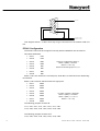
Multiport User Manual Teletrend Multitrend Circitrend 43-TV-25-03 GLO Issue 2 01/01 UK 43-TV-25-03 GLO Issue 2 01/01 UK Table of Contents Table of Contents i TrendManager Pro Site License Agreement ....................................................... iii Preface - Honeywell ................................................................................................ iv Chapter 1: Introduction 1 Summary .................................................................................................................... 1 Specifications ............................................................................................................ 1 Recorders ............................................................................................................... 1 PC Requirements ................................................................................................... 1 Installation and Connection .................................................................................... 1 PC241i Configuration. .......................................................................................... 2 Installation ............................................................................................................. 3 Chapter 2: Communications Operation 5 ................................................................................................................... 5 Appendix A 7 Important points about Trendbus ........................................................................... 7 Purpose .................................................................................................................. 7 Functions ............................................................................................................... 7 Data Acquisition .................................................................................................... 7 Appendix B 9 Trendbus Trouble-shooter ....................................................................................... 9 RS485 Communications ......................................................................................... 9 Recorder Configuration ......................................................................................... 9 TrendManager Pro Configuration ......................................................................... 9 Redundant System .................................................................................................. 9 Continuous RX Errors ......................................................................................... 11 Index 4 3 -T V- 2 5 -0 3 G L O I s s u e 2 0 1 / 0 1 U K 13 i ii 4 3 - TV -2 5 -0 3 G L O I s s u e 2 01/ 01 UK TrendManager Pro Site License Agreement This License Agreement is your proof of license. Please treat it as valuable property. This is a legal agreement between you (either an individual or entity), the end user, and Honeywell. If you do not agree to the terms of this Agreement, promptly return the disk package and the accompanying items (including written materials and binders or other containers) to the place you obtained them for a full refund. Honeywell TrendManager Pro Grant of License Honeywell grants to you the right to use the software program identified above on an individual computer. For the purposes of this Agreement, "use" means loading the software into RAM as well as installation on a hard disk or other storage. You may access the software from a hard disk, over a network, or any other method you choose, so long as you comply with this Agreement. Your registration number, which will be required in ager Pro to enter for Trendbus use, is: TrendMan- 36 26 43 33 4 3 -T V- 2 5 -0 3 G L O I s s u e 2 01/01 UK iii Preface - Honeywell Communications There are two types of RS485 network communications that can be used with Honeywell recorders for the purposes of downloading data to a host in real time. Trendbus is a Honeywell protocol that is used in conjunction with the Windows-based TrendManager Pro software. This allows real-time downloading of data to a host PC which TrendManager Pro uses to create real-time graphs and update records of the set-ups for each recorder in the network. Trendbus is explained in Chapter 1 of this manual. Modbus™ is an industry standard protocol used in many SCADA packages for network control. This allows Honeywell recorders to be inserted into existing networks using Modbus™ or linked directly to a controller over an RS485 link. Modbus™ is explained in Chapter 2. iv 4 3 - TV -2 5 -0 3 G L O I s s u e 2 01/ 01 UK Chapter 1: Introduction Summary Trendbus is an RS485 serial communications protocol developed by Honeywell. It enables 32 recorders to be linked to each comms port in a network configuration, with each recorder transferring information to a single PC. Using TrendManager Pro, data from selected pens on any of the networked recorders can be imported to the TrendManager Pro database and displayed onto graphs in real time. Trendbus Multiport offers the same features, but uses up to 8 RS485 ports at the same time on the same PC, enabling up to 256 recorders to be connected to the same PC. Further instructions are found in the Honeywell V5 User Manual and the TrendManager Pro on-line Help facility and references to these aids are made in this manual where necessary. Specifications Recorders Any model of Honeywell recorder may be installed in a Trendbus network. See Chapter 12 of the Honeywell V5 User Manual on how to check the firmware version of your recorder. The recorder must also be fitted with an RS485 communications card. PC Requirements The PC must be fitted with the Amplicon PC241i RS485 card and must be running Windows NT. The Trendbus communications configuration is included in TrendManager Pro, and as such your PC must be of the standard specified in the Installation Instructions that accompany TrendManager Pro. Installation and Connection Trendbus networks are subject to standard RS485 specifications. This section details the setup of the Amplicon 8 channel isolated RS485 card, the PC241i. 4 3 -T V- 2 5 -0 3 G L O I s s u e 2 01/01 UK 1 1 S creen 6 2 7 3 8 4 9 5 A /A ' R ec ord er B /B ' R ec o rd er This diagram shows 1 of the 8 nine way D Type connectors on the PC241i break out box. PC241i Configuration The PC241i card must be configured correctly before installation into the host PC. Card base addresses: • • • • • • • • Com 1 6A0 Com 2 6A8 Com 3 6B0 Com 4 6B8 Com 5 630 Com 6 638 Com 7 640 Com 8 648 These are configured by Switch 4: Switch 4 (SW4)= 11010110 Where 1 = ON + Up Position 8 sets IRQ group to 3,4,5,7 IRQ's 3,4 & 5 are used for the comms ports, while IRQ 7 is reserved for the 'Watchdog' I/O interface. IRQ's 3,4 & 5 must be shared across the eight ports: • • • • • • • • Com 1 IRQ 3 Com 2 IRQ 4 Com 3 IRQ 5 Com 4 IRQ 3 Com 5 IRQ 4 Com 6 IRQ 5 Com 7 IRQ 3 Com 8 IRQ 4 i.e. Switch 3 (SW3) = 00011000 Switch 2 (SW2) = 01100001 Switch 1 (SW1) = 11111111 Where 1 = On = Up The following jumpers must be IN: J111, J121, J131, J141, J151, J161, J171, J181. J112, J122, J132, J142, J152, J162, J172, J182. The following jumpers must be OUT: J110, J120, J130, J140, J150, J160, J170, J180. 2 4 3 - TV -2 5 -0 3 G L O I s s u e 2 01/ 01 UK Installation Ensure the switches and jumpers are configured as on the previous page, fit the card in the PC and run the setup.exe on the PC241i's Windows NT Serial Driver Disk and follow the instructions. After installing, delete the existing Com ports and add each of the 8 Amplicon ports, Com1 to Com8. Set the base addresses and IRQ's for each port as shown. Set RS485 half duplex to "None" and ensure the FIFO box is checked. Do not restart until all 8 ports have been added. Windows NT sometimes re-sets Com2 (and Com1), so it may take several attempts. If it is not possible to get 8 Amplicon ports as required, then the offending port should be set to 'default' settings and the Amplicon port configured as Com 9. The TMP.ini file (created in the Windows directory when TMP is first run) can then be modified to choose the actual port configured. e.g. • • • Unable to configure Com 2; Set Com 2 settings to "default"; Configure Com 9 instead, using the base address and IRQ for Com 2; In TMP.ini under the [COM2] heading change Port=COM2 to Port=COM9. Within TrendManager Pro the user will still refer to Com 2, and the port will still be "Channel 2" on the PC241i break out box. 4 3 -T V- 2 5 -0 3 G L O I s s u e 2 01/01 UK 3 4 4 3 - TV -2 5 -0 3 G L O I s s u e 2 01/ 01 UK Chapter 2: Communications Operation To start the Trendbus network running, select the Comms option in the Special Setups menu. Ensure that the Comms facility is enabled on each recorder in the network and that all recorders are set to the same baud rate. The remainder of the set-up procedure is performed in TrendManager Pro Version 4.9. Full information is contained in the TrendManager Pro Version 4.9 online Help facility, but a brief sequence of actions is given below for ease of reference. 1. From the Configure menu in TrendManager Pro Version 4.9, choose the Communications option. 2. From the Trendbus dialog box, check the Enable Trendbus box and enable the Comms ports on your PC to which the networks are connected. Select the same baud rate as on each of your recorders in each network. 3. Click on OK and the Communications Status window will appear. This window may be removed by clicking on the Close button and opened again by choosing Communications Status from the View menu, or minimise to the task bar. 4. Each recorder on the network should have a corresponding recorder on the TrendManager Pro Version 4.9 database. To check this select Recorders from the Configure menu - a list will appear with all the recorders on the database. The ID numbers of each of these recorders should be unique and should correspond to the ID numbers of the recorders in the network. (If you cannot find a networked recorder on the database, you may need to create one as described in the TrendManager Pro Version 4.9 Help section on Creating a New Recorder.) 5. For each networked recorder on the database activate the Recorder Configuration page and choose System. In the Comms section of the System settings make sure that the Enable Trendbus for this Recorder check box is ticked. Ensure the port is correct and set the storage frequency. 6. For each individual pen required on the network, go into the Comms section of the Pen Setups page. From there tick the Comms Pen Enable check box and decide upon the logging method and speed for data from that Pen. Further information on logging methods and speeds for Trendbus is given in Section 5 of this manual. 7. When the set-ups have been completed, click on OK in the Recorder Configuration page and that recorder will be added to the Communications Status window. Data will immediately be relayed from the selected pens on that recorder into the TrendManager Pro Version 4.9 database. With the recorders on the network being successfully linked to TrendManager Pro Version 4.9, information may be displayed as a graph. Create a graph in the normal way and identify the relevant pen either from the Data Locator or by adding a data source in the Graph Settings page. All the graphing functions are available and data transferred via both Trendbus and floppy disk can be presented on a 4 3 -T V- 2 5 -0 3 G L O I s s u e 2 01/01 UK 5 graph. When identifying a pen as a data source for a graph, the means by which the data for that pen was acquired is shown by the following symbols:- Data acquired from a Pen via Trendbus. Transferred to TrendManager Pro Version 4.9 via floppy disk. As data is received to a graph from networked recorders, the traces will eventually reach the edge of the graph. Selection of the Auto Scrolling option from the TrendManager Pro Version 4.9 toolbar will result in the graph being continuously redrawn with the latest data. 6 4 3 - TV -2 5 -0 3 G L O I s s u e 2 01/ 01 UK Appendix A Important points about Trendbus Purpose Trendbus is designed to allow the user to receive data from remote recorders, without having to retrieve the disk from the unit. It is not a substitute for recording data onto floppy disk, which can be done at speedier logging rates. Functions TrendManager Pro uses Trendbus to perform the following functions:- • • Retrieval of the current recorder set-up • Time synchronisation of networked recorders Retrieval of real-time data from individual channels on networked recorders at independent sampling rates and methods Setups can not be transferred to a recorder using Trendbus. Data Acquisition Data acquired using Trendbus is stored in a different location on the TrendManager Pro database from data transferred via floppy disk. The fastest logging rate is 1 second/log. The Communications Status window lists all the networked recorders on each port and reports if there is an error or interruption in data transfer between recorder and TrendManager Pro. For further information consult the on-line Help facility in TrendManager Pro, which gives comprehensive details on Communications set-ups, operations and features. 4 3 -T V- 2 5 -0 3 G L O I s s u e 2 01/01 UK 7 8 4 3 - TV -2 5 -0 3 G L O I s s u e 2 01/ 01 UK Appendix B Trendbus Trouble-shooter Follow these instructions to eliminate any Trendbus problems: RS485 Communications Check the configuration of the Amplicon eight channel comms card. Recorder Configuration 1. Ensure that each recorder is configured for Trendbus as follows: • • 2. In the Factory Hardware options, ensure RS485 TMP Comms is selected. In the Comms settings (Special Set-up menu) check that the baud rate is set correctly. Ensure that the recorder has the correct Unit ID Number, and that it is different on each recorder on each port. TrendManager Pro Configuration 1. Ensure that each recorder required to communicate using Trendbus is enabled to do so in the System settings for that recorder, and that the port enabled is the port to which it is physically connected. 2. Ensure that one or more pens are configured to receive Comms data in the Pen settings for that pen. 3. From the Configure Communications option, enable Trendbus and the ports, and then check that the baud rate is set to match the recorders on each respective port. Redundant System. When using the Honeywell D53129 "Watchdog" system, where two PC's running two TrendManager Pro packages are linked to form a redundant system, each PC will operate in either Master or Slave mode. • • Master Mode is when the PC is on line and storing data. Slave Mode, is when the PC is on stand-by and monitoring for Master fail. The Communications Status window will give the status for each recorder. The values displayed and their meanings are indicated overleaf. 4 3 -T V- 2 5 -0 3 G L O I s s u e 2 01/01 UK 9 In Master Mode Mode Description Initialising Trendbus is being configured. Downloading TrendManager Pro is attempting to download set-up information from the recorder. TrendManager Pro will request real-time data when required. Real-Time In Set-Up Configuration error Disabled Waiting The user has entered Set-Up on the recorder. During this time, no data is logged for the recorder, and once the user exits Set-Up the mode will change to “Downloading”. The pens selected for Comms do not correspond with the pens enabled on the recorder. A recorder has been removed from Comms operations. Occurs briefly at Start-Up and if the user enters Set-Up on the recorder. (blank) TrendManager Pro is retrying the operation. TrendManager Pro received nothing from the recorder. Work through the above checklist to ensure No Reply configuration is correct. If all is OK, then your PC is unsuitable for Trendbus operations. (See minimum PC specification.) RX Error TX Error Error Talking Talking * HotSwap TrendManager Pro received a reply from the recorder, but it was corrupt. If the error persists you may have a faulty connection on two recorders with the same ID Number. (See note below.) TrendManager Pro tried unsuccessfully to communicate with the recorder via Trendbus. If this persists check that you have identified a valid comms port on you PC. If this is OK then your PC is unsuitable for Trendbus operations. (See minimum PC specification.) A general comms error has occurred. Your PC is unsuitable for Trendbus operations. (See minimum PC specification.) Trendbus has received real-time data from the recorder. Trendbus is working correctly - Congratulations! Trendbus has received real-time data but it arrived later than expected. If this is a common occurrence then the system is too heavily loaded. The user should reduce the log rate for the pens of the recorder(s) in question. Hot-Swap may appear briefly during Database hot-swap. In Slave Mode Mode Description Monitoring TrendManager Pro is trying to monitor the bus for recorder messages. Listening No messages The slave has heard messages for this recorder. Nothing heard from this recorder. 10 4 3 - TV -2 5 -0 3 G L O I s s u e 2 01/ 01 UK Continuous RX Errors If RX Error messages occur in the Communications Status window, check that • • There is no faulty connection in the RS485 wiring There are no recorders in the network with the same ID number Then try amending the RX timeout in the TMP.ini file using a text editing package, such as Windows Notepad, to open the file. In the [comms] section of the file you will find a line Timeout = 150. Change the value to 200, then save and close the file. If frequent RX Error messages occur, try changing the Baud rate of the network, first to 19200, then, if that is not successful, to 9600. Remember to change the Baud rate on the recorders in the network as well as on TrendManager Pro. 4 3 -T V- 2 5 -0 3 G L O I s s u e 2 01/01 UK 11 12 4 3 - TV -2 5 -0 3 G L O I s s u e 2 01/ 01 UK Index A F Addresses ..................................................................... 2 B Firmware Version .................................................... 1 G Baud Rate .................................................................... 5 Grant of License C H Comms .......................................................................... 5 Comms Port ................................................................1 Communications ...................................................... 5 HotSwap Operation ..................................................................... 5 Configuration Error Connection ............................................. 10 Addresses .................................................................... 2 Installation .................................................................. 3 .....................................................iii .................................................................... 10 I In Set-Up ................................................................... 10 Initialising ................................................................. 10 Installation ................................................................. 3 D Data Acquisition ...................................................... 7 Data Source ................................................................6 Disabled ..................................................................... 10 Downloading ........................................................... 10 E Error L License Agreement ................................................iii Listening .................................................................... 10 N ............................................................................ 10 4 3 -T V- 2 5 -0 3 G L O I s s u e 2 01/01 UK No Messages ............................................................ 10 No Reply .................................................................... 10 13 O Operation VWXYZ .................................................................... 5 Baud Rate ................................................................... 5 Comms ........................................................................ 5 Data Locator ............................................................... 5 Data Source ................................................................ 6 Waiting ........................................................................10 Watchdog .....................................................................2 P PC Requirements ..................................................... 1 PC241i Configuration .......................................... 2 R Real-Time .................................................................. 10 Redundant System ................................................... 9 RS485 ....................................................................iv, 1, 9 RX Error .................................................................... 10 S Specifications ............................................................ 1 Firmware Version ...................................................... 1 PC Requirements ....................................................... 1 PC241i Configuration ............................................... 2 T Talking ........................................................................ 10 Talking * .................................................................... 10 Time Synchronisation ............................................ 7 Trendbus Comms Port ................................................................ 1 Data Acquisition ........................................................ 7 Redundant System ..................................................... 9 RS485 ...................................................................... 1, 9 Specifications ............................................................. 1 Time Synchronisation ............................................... 7 TrendView Communications ............................. iv RS485 ......................................................................... iv TX Error 14 .................................................................... 10 4 3 - TV -2 5 -0 3 G L O I s s u e 2 01/ 01 UK Please take a moment to complete this questionnaire Reputation 1 3 Products How do you perceive our range of products? How would you rate the reputation of Honeywell Tick as appropriate Tick as appropriate Products offered are better than those of competitors A very reputable, successful company Products offered are worse than those of competitors A reputable company Products offered are the same as those of competitors A disreputable company No views either way 2 Service How do you rate or perceive the following service levels provided by our sales staff? Tick as appropriate Excellent Good Fai r Response speed Quality of response Follow up response Overall level of servic e How do you rate or perceive the following service levels provided by our Technical Support Service? Tick as appropriate Excellent Good Fair Response speed Any other comments .............................................................................. .............................................................................. .............................................................................. Are there any products that we do not provide that you would like us to provide - or any we could improve on? .............................................................................. .............................................................................. .............................................................................. Improvements to existing products........................ . . .............................................................................. .............................................................................. .............................................................................. 4 General If you are an existing or new customer, what made you choose Honeywell. Only on pric e Quality of response Price plus a combination of factors Follow up response Overall level of servic e Prefer to deal with a reputable compan y How could our service be improved upon .......................................................................... .......................................................................... Honeywell offers more than the competition in terms of ’added value’ over and above the product itself How many times do you receive a visit from one of our Sales representatives? Visits every: Thank you for completing this questionnaire. 1-3 months Please fill out your name and address below. Photo copy this form and Fax to us on 3-6 months 6-12 months How does that compare to our competitors? More Less The sam e +44 (0)1202 476501 Name ..................................................... Score on a level of 1-10, with 10 being the best Company name ...................................... Address ................................................. Quality of manuals / sales literature Administration / documentation and letters Technical expertise of our sales staff Sales staff ability to give informed advice ............................................................... ............................................................... County................. Postcode................... The quality of the Honeywell sales team. Tel:........................ Fax.......................... Pricing Company business ................................ Honeywell understanding of your industry . ............................................................... 43-TV-25-03 GLO Issue 2 01/01 UK 15 Warranty/Remedy Sales and Service Honeywell warrants goods of its manufacture as being free of defective material and faulty workmanship. Contact your local sales office for warranty information. If warranted goods are returned to Honeywell during that period of coverage, Honeywell will repair or replace without charge those items it finds defective. The foregoing is Buyer’s sole remedy and is in lieu of all other warranties, expressed or implied, including those of merchantability and fitness for a particular purpose. While we provide application assistance, personally, through our literature and the Honeywell web site, it is up to the customer to determine the suitability of the product in the application. Honeywell serves its customers through a worldwide network of sales offices and distributors. For application assistance, current specifications, pricing or name of the nearest Authorised Distributor, contact your local sales office or: INTERNET: www.honeywell.com/sensing Specifications may change at any time without notice. The information we supply is believed to be accurate and reliable as of this printing. However, we assume no responsibility for its use. ARGENTINA BULGARIA GERMANY NORWAY HONEYWELL S.A.I.C. BELGRANO 1156 BUENOS AIRES ARGENTINA Tel. : 54 1 383 9290 HONEYWELL EOOD 14, Iskarsko Chausse POB 79 BG- 1592 Sofia BULGARIA Tel : 359-791512/ 794027/ 792198 HONEYWELL AG Kaiserleistrasse 39 D-63067 OFFENBACH GERMANY Tel. : 49 69 80 64444 HONEYWELL A/S Askerveien 61 PO Box 263 N-1371 ASKER NORWAY Tel. : 47 66 76 20 00 CANADA HONEYWELL Kft Gogol u 13 H-1133 BUDAPEST HUNGARY Tel. : 36 1 451 43 00 ASIA PACIFIC HONEYWELL ASIA PACIFIC Inc. Room 3213-3225 Sun Kung Kai Centre N° 30 Harbour Road WANCHAI HONG KONG Tel. : 852 829 82 98 AUSTRALIA HONEYWELL LIMITED 5 Thomas Holt Drive North Ryde Sydney NSW AUSTRALIA 2113 Tel. : 61 2 353 7000 AUSTRIA HONEYWELL AUSTRIA G.m.b.H. Handelskai 388 A1020 VIENNA AUSTRIA Tel. : 43 1 727 800 BELGIUM HONEYWELL S.A. 3 Avenue de Bourget B-1140 BRUSSELS BELGIUM Tel. : 32 2 728 27 11 BRAZIL HONEYWELL DO BRAZIL AND CIA Rua Jose Alves Da Chunha Lima 172 BUTANTA 05360.050 SAO PAULO SP BRAZIL Tel. : 55 11 819 3755 HONEYWELL LIMITED THE HONEYWELL CENTRE 529 Mc Nicoll Avenue M2H 2C9 NORTH YORK, ONTARIO CANADA Tel. : 416 502 5200 CZECH REPUBLIC HONEYWELL, Spol.s.r.o. Budejovicka 1 140 21 Prague 4 Czech Republic Tel. : 42 2 6112 3434 DENMARK HONEYWELL A/S Automatikvej 1 DK 2860 Soeborg DENMARK Tel. : 45 39 55 56 58 FINLAND HONEYWELL OY Ruukintie 8 FIN-02320 ESPOO 32 FINLAND Tel. : 358 0 3480101 FRANCE HONEYWELL S.A. Bâtiment « le Mercury » Parc Technologique de St Aubin Route de l’Orme (CD 128) 91190 SAINT-AUBIN FRANCE Tel. from France: 01 60 19 80 00 From other countries: 33 1 60 19 80 00 HUNGARY POLAND HONEYWELL Sp.z.o.o UI Domainewksa 41 02-672 WARSAW POLAND Tel. : 48 22 606 09 00 ICELAND HONEYWELL Hataekni .hf Armuli 26 PO Box 8336 128 reykjavik Iceland Tel : 354 588 5000 PORTUGAL HONEYWELL PORTUGAL LDA Edificio Suecia II Av. do Forte nr 3 - Piso 3 2795 CARNAXIDE PORTUGAL Tel. : 351 1 424 50 00 ITALY HONEYWELL S.p.A. Via P. Gobetti, 2/b 20063 Cernusco Sul Naviglio ITALY Tel. : 39 02 92146 1 MEXICO HONEYWELL S.A. DE CV AV. CONSTITUYENTES 900 COL. LOMAS ALTAS 11950 MEXICO CITY MEXICO Tel : 52 5 259 1966 THE NETHERLANDS HONEYWELL BV Laaderhoogtweg 18 1101 EA AMSTERDAM ZO THE NETHERLANDS Tel : 31 20 56 56 911 REPUBLIC OF IRELAND HONEYWELL Unit 1 Robinhood Business Park Robinhood Road DUBLIN 22 Republic of Ireland Tel. : 353 1 4565944 REPUBLIC OF SINGAPORE HONEYWELL PTE LTD BLOCK 750E CHAI CHEE ROAD 06-01 CHAI CHEE IND. PARK 1646 SINGAPORE REP. OF SINGAPORE Tel. : 65 2490 100 REPUBLIC OF SOUTH AFRICA HONEYWELL Southern Africa PO BOX 138 Milnerton 7435 REPUBLIC OF SOUTH AFRICA Tel. : 27 11 805 12 01 ROMANIA HONEYWELL Office Bucharest 147 Aurel Vlaicu Str., Sc.Z., Apt 61/62 R-72921 Bucharest ROMANIA Tel : 40-1 211 00 76/ 211 79 RUSSIA HONEYWELL INC 4 th Floor Administrative Builiding of AO "Luzhniki" Management 24 Luzhniki 119048 Moscow RUSSIA Tel : 7 095 796 98 00/01 SWITZERLAND HONEYWELL A.G. Hertistrasse 2 8304 WALLISELLEN SWITZERLAND Tel. : 41 1 831 02 71 TURKEY HONEYWELL Otomasyon ve Kontrol Sistemlen San ve Tic A.S. (Honeywell Turkey A.S.) Emirhan Cad No 144 Barbaros Plaza C. Blok Kat 18 Dikilitas 80700 Istanbul TURKEY Tel : 90-212 258 18 30 UNITED KINGDOM HONEYWELL Unit 1,2 &4 Zodiac House Calleva Park Aldermaston Berkshire RG7 8HW UNITED KINGDOM Tel : 44 118 906 2600 SLOVAKIA U.S.A. HONEYWELL Ltd Mlynske nivy 73 PO Box 75 820 07 BRATISLAVA 27 SLOVAKIA Tel. : 421 7 52 47 400/ 425 HONEYWELL INC. INDUSTRIAL CONTROLS DIV. 1100 VIRGINIA DRIVE PA 19034-3260 FT. WASHINGTON U.S.A. Tel. : 1-800-343-0228 SPAIN HONEYWELL S.A Factory Josefa Valcarcel, 24 28027 MADRID SPAIN Tel. : 34 91 31 3 61 00 VENEZUELA HONEYWELL CA APARTADO 61314 1060 CARACAS VENEZUELA Tel. : 58 2 239 0211 SWEDEN HONEYWELL A.B. S-127 86 Skarholmen STOCKHOLM SWEDEN Tel. : 46 8 775 55 00 This publication does not constitute a contract between Honeywell and its customers. The contents may be changed at any time wit hout notice. It is the customer’s responsibility to ensure safe installation and operation of the products. Detailed mounting drawings of all products ill ustrated are available on request. Honeywell 2001. All rights reserved. Sensing and Control www.honeywell.com/sensing Honeywell 4 Airfield Way Christchurch, BH23 3TS Dorset, U.K. 43-TV-25-03 GLO Issue 2 01/01 UK