1
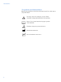
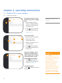
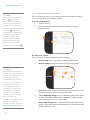
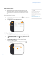
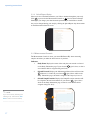
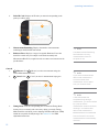
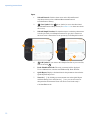
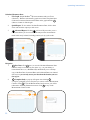
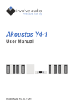
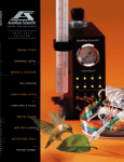
header user’s guide v 3.0 header BioDentTM is a trademark of Active Life Scientific, Inc. ©Active Life Scientific, Inc. Santa Barbara, California 2 888.906.7770 www.activelifescientific.com header table of contents 1. introduction....................................................5 1.1 Intended Use.........................................5 1.2 BioDentTM Hfc System Technical Specifications........................................5 1.3 Safety Warnings and Precautions.........5 1.4 Confidential Information and Computer Network Safety.....................7 1.5 Symbols and Abbreviations...................8 4.2.1 Probe Friction, Damage and Corrosion................................................ 25 4.3 Measurement Head Unit (MHU).........26 4.3.1 Unusual F-D Graph Curves................. 26 4.4 Sample Preparation............................ 26 4.4.1 Accessibility of Measurement Area..... 26 4.4.2 Sample Hydration................................ 26 4.4.3 Direction and Orientation.................... 26 4.5 Control Software................................. 26 2. getting started................................................9 4.5.1 USB Connection not Recognized........ 26 2.1 Supplies................................................ 9 2.1.1 Required................................................ 9 2.1.2 Recommended...................................... 9 2.2 Setting It Up........................................10 3. operating instructions.................................14 3.1 BioDentTM Hfc Control Software..........14 3.1.1 Study Information................................ 14 3.1.2 Measurement Protocol Setup.............. 15 3.1.3 Sample Planning................................. 16 3.1.4 Quick Report Setup............................. 17 3.1.5 Measurement Console........................ 17 3.1.6 Advanced Report................................. 21 3.2 Hardware............................................22 3.2.1 Zero the Reference Force Display...... 22 3.2.2 Prepare BioDentTM Hfc for Measurements.................................... 23 3.2.3 Prepare the Measurement Head Unit (MHU) for your First Measurement.............. 24 3.2.4 Continue Measuring the Same Sample in Different Locations............. 24 3.2.5 Measure Additional Samples............... 24 4. troubleshooting...........................................25 4.1 General Considerations......................25 4.2 Probe Assembly Considerations.........25 4.6 Measurement Stand............................ 26 4.6.1 Measurement Stand not Turning On... 26 5. cleaning, care, and maintenance...............27 5.1 Life Expectancy...................................27 5.2 Periodic Maintenance.........................27 5.3 Cleaning Instructions/Precautions......27 5.4 Fuse Replacement..............................27 6. theory of operation......................................28 6.1 Introduction.........................................28 6.1.1 Measurement Head Unit (MHU).......... 28 6.1.2 Measurement Stand............................ 28 6.1.3 Probe Assemblies............................... 29 6.1.4 Workstation......................................... 29 6.2 Why Care about Material Properties?..........................................29 6.3 Conventional Methods........................29 6.4 Reference Point Indentation Methods: BioDentTM Hfc.......................29 6.5 What Is BioDentTM Hfc Measuring?.....30 6.6 Indentation Theory for BioDentTM Hfc......................................30 6.7 Calculated Data..................................30 3 header 4 header chapter 1. introduction 1.1 intended use BioDentTM Hfc (BioDentTM) is designed for specific tasks: making indentation measurements on calcified and hard materials ex vivo and in vivo. BioDentTM Hfc is For Research Use Only. Not for use in Diagnostic Procedures. BioDentTM Hfc has not been cleared or approved for diagnostic procedures by the U.S. Food and Drug Administration (FDA) or any foreign equivalent. BioDentTM is the world’s first commercially available Reference Point Indenter. 1.2 BioDentTM Hfc system technical specifications Measurement force range (accuracy)........................2.0N–10.0N (±0.1N) Measurement indentation frequency.........................2Hz Indentations per measurement (cycles).....................1–20 cycles *Pre-conditioning indentation force..........................0.5N-10N *Pre-conditioning indentations per second...............0.1Hz-5Hz *Pre-conditioning indentations per measurement (cycles).....................................................................1-20 cycles Resolution Force................................................................0.03N Distance............................................................1µm Measurement (raw) data file format............................CSV text file, tab delimited USB connectivity........................................................1.1/2.0 compliant Nework connectivity...................................................Gigabit Ethernet port 54 MB/s wireless note BioDentTM is intended to be used for laboratory research and not used for diagnostic or therapeutic purpose. BioDentTM is not intended for determining the safety and effectiveness of product(s). ✎ *Figures are approximate. Actual performance during pre-conditioning may vary. 1.3 safety warnings and precautions Warnings 5 1. Do not use on live humans. 2. The Probe Assembly (probe) used for indentation measurements is sharp and may be hazardous to the user. Use extreme caution when handling, using, and disposing of probes. To prevent accidental contact with the probe, remove it when the instrument is not in use. 3. This instrument is designed for use solely by researchers familiar with electromechanical laboratory instruments and with common laboratory safety procedures. 4. Dangerous voltages are present inside the Measurement Stand (chassis). Attempting to open or service the instrument will void your warranty. warning! To ensure the safe operation of this instrument, heed all warnings and follow instructions. Ignoring warnings or using the product in a manner other than the recommended may place you and other parties at risk. introduction caution! Damage to equipment or data is possible if instructions concerning proper use of the instrument and accessories are not adhered to. 5. Do not immerse the instrument in liquid or spray liquids directly onto the instrument. 6. The instrument contains no user-serviceable parts. Removing the cover may introduce an electric-shock hazard through exposure to high voltages and other risks. If the instrument malfunctions, do not attempt repair on your own. Contact Customer Care at [email protected] for instructions on how to return it to an authorized Active Life Scientific Service Center for service. 7. Instrument installation shall be in accordance with the requirements of IEC 61010-1, Safety Requirements for Electrical Equipment for Measurement, Control, and Laboratory Use. 8. The instrument is not suitable for use in the presence of flammable gases and should be located away from combustible materials. 9. Instrument grounding is vital for safe operation. Plug power cord into a properly earthed main supply outlet with voltage and frequency characteristics that are compatible with those listed on the instrument and its corresponding manual. 10. Do not use plug adapters or extension cords. Such devices will defeat the safety ground and may cause injury. Inspect the power cord and other cables routinely and discontinue use immediately if damage is discovered. ✎ note Only authorized service technicians may perform repairs, adjustments, or alterations to the instrument and its accessories. Any violation voids the manufacturer’s warranty. Authorized service technicians are trained and certified by the manufacturer. 6 11. For the protection of service and shipping personnel, instruments and accessories being returned for repair must be prepared in accordance with the terms of Active Life Return Material Authorization. The manufacturer has the right to refuse to make repairs if the instruments or accessories are contaminated. Precautions 1. Do not use the instrument with incompatible equipment or with accessories that are not authorized by Active Life Scientific. Doing so may result in unreliable operation and may void certifications and warranties. 2. Always observe proper shutdown procedure. Failure to do so may result in corruption and/or loss of data. 3. The warranty becomes void and the manufacturer is not liable for direct or resulting damage if: a. the instrument or the accessories are improperly used, prepared or maintained; b. the instructions in the User’s Guide are not adhered to; introduction c. non authorized persons perform repairs, adjustments, or alterations to the instrument or accessories; or d. non authorized persons open the device. 4. This instrument should only be used in compliance with its intended use. 5. With the exception of the Probe Assembly and application stages, do not expose the instrument to moisture or operate in wet areas. 6. Ensure the power supplied to the instrument matches the power requirements printed on the rear of the instrument near the power inlet module. 7. For continued protection against risk of fire, replace fuses with T1.0A, 250 V type only. 8. Do not excessively bend or kink the instrument power cord or connecting cables. 9. Handle the instrument carefully as it is a calibrated, high-precision instrument. If the instrument is dropped or otherwise damaged, contact Active Life Scientific immediately. 10. Handle the probe with caution. The probe features a small diameter shaft which, if bent, may result in inconsistent measurements. Inspect the probe before each use for damage. If probe is bent or otherwise damaged (or if probe is expired), discard the probe. 11. The instrument includes a protection fuse at the power entry point. If the fuse fails, it may be removed and replaced with a new one. If the replaced fuse fails, the instrument must be serviced by an authorized Active Life Scientific technician. Failure to observe safety warnings and precautions contained herein may result in injury to the user or third parties and may invalidate the instrument warranty. 1.4 confidential information and computer network safety Information entered into BioDentTM Hfc can be accessed by others. Protecting data and other confidential information is your responsibility and not that of BioDentTM Hfc or Active Life Scientific. 7 ✎ note See section 5.4 for information on fuse replacement. introduction 1.5 symbols and abbreviations Reference the guide below to learn what each symbol in this User’s Guide and on your product means. 8 i The safety of the user or third party is at risk. Follow all product warnings and instructions for safe operation. Refer to User’s Guide instructions for proper operation of the instrument. Hazardous voltages are present in the device. Manufacturer information. Date of manufacture of the device. chapter 2. getting started Refer to the BioDentTM Hfc Setup Guide for proper setup procedure. Once complete, proceed below to ensure you have everything you need to begin taking measurements. 2.1 supplies 2.1.1 Required 1. BioDentTM Hfc 2. Approved Active Life Probe Assembly 3. Approved Active Life Reference Material 2.1.2 Recommended Application Stage Using the proper application stage to achieve optimal sample positioning and stability is extremely important. We recommend an approved Active Life application stage to hold and position your materials. Pictured below is the Ex-Vivo Small Bone Stage, available for testing ex vivo small rodent bones. Probe Assembly Cleaning Supplies For recommended Probe Assembly cleaning supplies, see instructions for Probe Assembly Care, available at www.activelifescientific.com. Lab Supplies Commonly used supplies may include: protective gear (gloves, face mask, etc.), surface coverings, and sample handling apparatus (tweezers, tray). 9 4. Test sample or material headerOvest virmiss imoliqu onlocum is getting started unt? Solibul trum nimus, et adeati, 2.2 setting it up Follow these simple steps to begin taking measurements: Step 1 Turn on BioDentTM Hfc’s computer. Turn on BioDentTM Hfc’s monitor. Ensure there is nothing on Sample Plate. Turn on BioDentTM Hfc. Step 2 If applicable, attach your Active Life approved application stage according to the instructions provided with the stage. Don’t attach the Probe Assembly or samples yet! There are a few more steps... Step 3 Open BioDentTM Hfc’s Control Software by double clicking the desktop icon. 10 getting started Step 4 caution! Firmly hold MHU with your left hand. Press button with your right thumb to release the MHU positioning lock. While pressing button, either raise or lower MHU into position 1 (for larger/taller samples) or position 2 (for smaller/shorter samples). Release button to lock position. Do not force the MHU. Ensure the button is fully pressed. Pushing too hard may cause it to jam. Contact Customer Care if assistance is needed customer.care@ activelifescientific.com. Step 5 Navigate through the BioDentTM Hfc Control Software (see Chapter 3) until you reach the Measurement Console screen (section 3.1.5). Then complete steps 6 and 7. Step 6 Attach and position your sample. If you are using an Active Life approved application stage consult the instructions provided with it to ensure correct sample attachment and positioning. 11 ✎ note Sample positioning is extremely important! Adhere to instructions provided with your stage at all times. Additional stage instruction and guidance documents are available at www.activelifescientific.com. getting started Step 7 Use the following instructions to attach your Probe Assembly (probe). After completing this step, return to section 3.1.5, Operating Instructions, Measurement Console. ✎ note It is highly recommended that you read and understand the Sample Positioning, Stability and Probe-Sample Guidance Document available at www.activelifescientific.com. The Probe Assembly is sharp and may be hazardous to the user. Use extreme caution when handling, using, and disposing of probes. To prevent accidental contact with the probe, remove it when the instrument is not in use. square hub Test Probe Reference Probe Probe Assembly Carefully remove the Probe Assembly from its packaging and protective foam. With the Test Probe and the Reference Probe coupled, hold the Probe Assembly by the Reference Probe’s square hub. 12 While holding the Probe Assembly by the square hub, insert the top of the Test Probe into the opening of the Measurement Head Unit (MHU); there is an automatic magnetic attachment you will feel if inserted correctly. Hold the black wheel still with your free hand. As you push the Reference Probe up, ensure the Reference Probe engages the thread. Once it does, gently twist it counterclockwise until finger tight. 13 chapter 3. operating instructions 3.1BioDentTM Hfc control software 3.1.1 Study Information To continue a study or to access data from a previous or ongoing study 1. Select the study from the Previous or Ongoing Studies drop-down menu on the left side of the screen. 2 1 What kind of study are you running? 2. Click > (Next) to advance to the Measurement Console (section 3.1.5). To start a new study 1. Enter the name of your study. 1 4 2 2. Indicate who will be conducting the study. 3. Include a description of your study (optional). 3 4. Click > (Next) to advance to the Measurement Protocol Setup screen. 2 1 To get started quickly—if you don’t have a specific study in mind or simply want to explore protocol ideas before saving them to the Protocol Library 1. Click >> (Quick Start) to advance to the Measurement Console (section 3.1.5). To exit the program 2. Click < Exit Program to exit the program. 14 caution! Clicking >> opens the Control Software in Quick Study mode and disables the ability to save study settings and measurement data. Keep the Quick Study mode open to review data in Quick and Advanced Reports, and to create and save new protocols. Remember: you can neither save data nor access that study later in a Quick Study. operating instructions ✎ note Unless you choose Temporary, clicking > will save your new or modified protocol to the Protocol Library and add it to the Select from Protocol Library drop-down menu for later access. If you click > and are told, “Protocol Name Already Exists,” the protocol may already be saved to the Library. If this happens, click Use Existing, select the protocol from the Select from Protocol Library drop-down menu, and click > . 3.1.2 Measurement Protocol Setup This section describes how to access existing protocols from the Protocol Library, create a new protocol or use a temporary protocol. To use an existing protocol 1. Click Use Existing. 2. Select the existing protocol from the Select from Protocol Library drop-down menu. 1 2 To create a new protocol Click Create New and enter the following inputs accordingly. a. Protocol Name. Give your protocol an easily identifiable name. b. Protocol Author(s). The names of those who created the protocol. ✎ note Select Enable Pre-Conditioning and define your pre-conditioning protocol if the surface of your test material is either not easily identifiable or extremely rough, e.g., material covered by other material, such as bone covered by soft tissue. There are three inputs to set: Pre-Conditioning Indentation Force (N), Pre-Conditioning Indentations per Second (Hz), and Pre-Conditioning Indentations per Measurement (Cycles). Find range and increment values for each in the Technical Specifications table. 15 a c b d c. e Notes. Notes to help identify the intended use of this protocol, e.g., if the protocol is ideal for testing bare bone (no soft tissue). d.*Pre-Conditioning Settings. Use pre-conditioning settings if the surface of your test material is either not easily identifiable or extremely rough. *Pre-conditioning parameters are approximate e. Measurement Settings. Enter a protocol that will produce data for later analysis. Set the following inputs: Indentation Force (N) and Indentations per Measurement (Cycles). operating instructions To use a temporary protocol f. Check the Temporary box to create a protocol that doesn’t save to the Protocol Library. This is a good option when developing a protocol you eventually want to save because it won’t save drafted protocols along the way. Other required inputs: Navigation g. After entering the protocol you want to use, click > (Next) to proceed to Sample Planning or h. Click < (Back) to return to Study Information. h g f 3.1.3 Sample Planning 1. New Sample/Location(s). Enter the name of the first sample you plan to measure and/or the location you plan to measure on that same first sample. 2. + Add Sample/Location(s). Click + (Add) to add the sample name/ location to the list. Repeat for all samples in the study. 3. Current Sample/Location. This shows the Samples/Locations that have been added to your list. a. To remove a Sample/Location, highlight it and click (Remove). 1 3a 2 3 16 - ✎ note If you are unsure about the optimal settings for your protocol, consult the Protocol Creation Guidance Document available at www.activelifescientific.com. operating instructions 3.1.4 Quick Report Setup Select up to five Calculated Parameters you’d like to monitor throughout your study. Click > to proceed to the Measurement Console or < Back to return to Sample Planning. If you change your mind about the parameters you would like to monitor, they can be changed during your study by clicking the Quick Report drop down menus on the Measurement Console screen. 3.1.5 Measurement Console The Measurement Console is where you control BioDentTM Hfc when measuring samples and where you make the initial review of your data. Indicators 1. Study Name. Displays the name of the study that was entered or selected on the Study Information page. If you selected >> (Quick Start), no data is saved and this field is assigned with Quick Study. ✎ note If you are currently following the “Setting it Up” instructions, click here to return for the next step. ___________________________ 17 2. Selected Protocol. Displays the Measurement Protocol that will run when (Measure) is clicked. If you selected >> (Quick Start) while on the Study Information page, this field is assigned with Temporary Protocol. 3. Selected Sample/Location. Displays the Sample/Location name that will be assigned to the next measurement. If you selected >> (Quick Start) while on the Study Information page, no data is saved and this field is assigned with Quick Study. 1 3 2 operating instructions 4. Probe ID Code. Displays the ID code you entered corresponding to the probe you will be using. 6 4 5 5. Measurements Remaining. Displays the number of measurements remaining for the Probe ID code entered. 6. Reference Force. Displays a range of acceptable Reference Force that should be exerted onto your sample via the Probe Assembly and Measurement Head Unit; required in order to actuate a measurement at the specified force. Controls 1. 2. Measure. Click (Measure) to take a measurement using the selected Measurement Protocol. x Cancel. Click x (Cancel) to cancel a measurement in progress. 2 1 3 3. 18 Tuning Mode. Click the corresponding box to enable the Tuning Mode feature prior to each study and as necessary during your study. Tuning Mode should be used when you are adjusting Touchdown Distance (TDD) within the acceptable 50-250µm range. See section 3.2.2 for TDD adjustment instructions. ✎ note The Measurements Remaining field indicates how many measurements remain for the probe in use. ✎ note If you cancel a measurement, data for that measurement will not be saved and a measurement will not deduct from your Probe ID Code. ✎ note If TDD falls outside the acceptable range during a measurement, you will be notified by a pop-up and the measurement will been canceled, resulting in no measurement data for that measurement. Measurements are not deducted from the Probe ID count when measurements are automatically canceled. operating instructions Inputs 1 1. Selected Protocol. Click the down arrow on the Selected Protocol drop-down menu to select a different Measurement Protocol from the Protocol Library. 2. Gear Symbol. Click (Gear Symbol) to access the abbreviated Measurement Protocol Setup screen (see section 3.1.2 to learn more about this screen). 3. Selected Sample/Location. Click the down arrow on the drop down menu to load a previously saved Sample/Location. If a grey bar is shown over the down arrow it means there are no previously saved Sample/Locations. 2 4 3 5 6 7 19 4. + Add Symbol. If you want to add a Sample/Location to your saved list, enter it and click + . 5. Probe Identification Code. The code you entered will be displayed. To use a different one, enter the new BioDentTM Hfc Probe ID Code. 6. Quick Report. Displays calculated data for the parameters selected in the Quick Report Setup screen. 7. Notes for [ ]. By clicking on a measurement row in the Quick Report and then entering text in the Notes for [ ] box, you can save notes for that particular measurement. Notes will also be saved in the study’s CalculatedData.txt file. 4 operating instructions Calculated Parameter Data 1. F-D Graph. Graphs BioDentTM Hfc measurement results on a Force (Newtons) – Distance (micrometers) graph in real time. The plotted data of the most recent measurement will remain on the graph until the (Measure) button is clicked again. 2. Quick Report. To view other Calculated Parameter Data, click a down arrow and select the output you wish to see. 3. Advanced Report. Clicking (Advanced Report) takes you to a screen that allows you to review the data from previous measurements made in this study in detail, including certain cycle-by-cycle results. 3 1 2 3 Navigation 1. Save Data. Click (Save) to save the Calculated Parameter Data from this study to a location of your choice (e.g., on your desktop, a network hard-drive, etc.). BioDentTM Hfc automatically saves a backup copy of the Raw Data, Converted Data, and Calculated Data to an internal directory but you can only access your data from the location you save the copy to. 2. Complete Study. A pop-up will appear after clicking (Complete) prompting you to verify that you want to exit the Measurement Console. Click to exit the Measurement Console screen; you will be redirected to the Study Information screen. Click x to stay on the Measurement Console screen. 1 2 2 20 operating instructions 3.1.6 Advanced Report 1. Select Measurement. Click the Select Measurement down arrow to select a measurement from your study to review in more detail. 2. Select Graph to Display. Click the Select Graph to Display down arrow to view other calculated parameter data for the selected measurement. 2 1 3. Graph Manipulation Tools. Tools to view graphs in different ways. a. Cursor movement tool (left). Moves the cursor on the display. b. Zoom (middle). Provides in/out zoom options on the display. c. Panning tool (right). ‘Grabs’ the plot and moves it around the display. (3a) (3b) (3c) (Enlarged view of Graph Manipulation Tools) 3 4. 21 Zoom Options a. Zoom to rectangle (top left). Use this to draw a box around an area on the graph that you would like to zoom in on. b. X-zoom (top middle). Use this to zoom in on an area of the graph along the x-axis. c. Y-zoom (top right). Use this to zoom in on an area of the graph along the y-axis. operating instructions 5 4 (4a) (4b) (4c) (4d) (4e) (4f) (Enlarged view of Zoom Options) 5. d. Zoom to fit (bottom left). Use this to return to the original view BioDentTM Hfc showed you. e. Zoom out from a point (bottom middle). Use this to click a point you want to zoom out from. f. Zoom in from a point (bottom right). Use this to click a point you want to zoom in on. < Back to Console. Click < Back to Console to go back to the Measurement Console screen. 3.2 hardware After your sample is attached and positioned to its starting location and your Probe Assembly is properly attached (see section 2.2) with a valid Probe ID Code entered in the software, you may progress to section 3.2.1. 3.2.1 Zero the Reference Force Display Ensure there is nothing on the Sample Plate before turning on the Measurement Stand. Once turned on, set the reference force scale to zero by pressing the TARE button on the right of the Reference Force Display. It should be the last thing you do prior to taking a measurement. 22 operating instructions 3.2.2 Prepare BioDentTM Hfc for Measurements Prepare BioDentTM Hfc for measurements by following Tuning instructions below. 1. 1 2 2. Position PMMA. Place a block of PMMA on the Sample Plate, then TARE the scale so it reads “0g”. 3. TDD Assessment. First, you will need to achieve a Reference Force within the acceptable Reference Force range. Take note of the Reference Force range, displayed below the Measure button, just above the F-D graph. Locate the large knobs towards the rear of the Measurement Stand and rotate them towards you to lower the MHU so the Probe Assembly makes contact with the PMMA. Continue lowering the MHU until the Reference Force displayed on the Measurement Stand’s blue Reference Force Display is within the range displayed on the Measurement Console screen. Once satisfied, click (Measure). You will now use this first measurement to adjust your TDD. As previously mentioned, the acceptable TDD range is between 50-250µm. Observe the TDD achieved on the “TDD (1st)” read out, below the F-D graph. If your TDD is not within the acceptable range, you will need to adjust it by rotating the black wheel that is between your Probe Assembly and the MHU. 4. Adjust TDD. When deciding which direction to rotate the wheel, think of it as a clock that you are adding time to or taking time away from – however, in this instance, you’re adding or taking away TDD. If the TDD achieved is above 250µm, rotate the wheel counter-clockwise in order to reduce TDD, and vice-versa. 23 Ensure BioDentTM Hfc is in an Operable State. Enable the Touchdown Distance (TDD 1st) Tuning Mode by clicking the Tuning Mode box below the Force-Distance (F-D) graph. You will know the Tuning Mode is on when a check mark appears in the corresponding box. This mode will allow you to physically adjust your TDD within the acceptable range of 50-250µm. Because Tuning Mode will be used for fine tuning your system, and not for collecting data, checking the box will prevent measurements from being deducted from your Probe ID Code. Tuning Mode can also be used for training purposes, but when enabled, BioDentTM Hfc will not save or calculate any data from those measurements. To do this, lift the MHU by using the large knobs – make sure you get enough clearance from the PMMA to prevent any damage to the Probe Assembly. Then, calculate the approximate difference between the TDD achieved and the desired TDD. One full revolution of the wheel is about 360µm – a good fact to keep in mind when deciding how much to rotate the wheel. Rotate the wheel in whichever direction necessary. After moving the PMMA over slightly to ensure you’re measuring a new location, lower the MHU back down by turning the large knobs toward you until the Probe Assembly makes contact with the PMMA and achieves proper Reference operating instructions Force. The measurement and adjustment process is repeated until you achieve acceptable TDD. 5. Disable Tuning Mode. Once you finish adjusting TDD, disable the Tuning Mode by clicking the corresponding box, located below the F-D graph. You’ll know it’s disabled when the box no longer has a check mark in it. 3.2.3 Prepare the MHU for your First Measurement Verify your measurement protocol on the Measurement Console before proceeding. 1. 2. Lower the MHU such that: a. You reach a reference force within the Reference Force range. b. Your probe makes good, solid and stable contact with the measurement location of your sample. This must be done correctly. ✎ note See the Active Life Guidance Document titled Sample Positioning, Stability and Probe-Sample Guidance Document available at www. activelifescientific.com. Click Measure. You should now see Force-Distance (F-D) measurement data graphed in real time in the Measurement Console. If you don’t see an F-D graph, refer to the Troubleshooting chapter of this User’s Guide (see Chapter 4). 2 3.2.4 Continue Measuring the Same Sample in Different Locations Once the current measurement is complete (indicated by a tone and the addition of a new row of Calculated Data in the Quick Report), raise the MHU and reposition your sample to the next desired location. Repeat Steps 1 and 2 until you finish taking measurements on the current sample. 3.2.5 Measure Additional Samples Repeat sections 3.2.3 and 3.2.4 for remaining samples. 24 warning! Always remove the Probe Assembly from the MHU and store in its original container before placing your hands in or near its path, and whenever system is not in use. chapter 4. troubleshooting 4.1 general considerations If your BioDentTM Hfc does not take measurements when you click check for the following common issues. (Measure), Power: Is everything turned on? • Measurement Stand • Reference Force Scale LCD Display • Computer • Monitor • Mouse (Check to see if there is an on/off switch on the bottom of the mouse provided with your BioDentTM Hfc) • Keyboard (Check to see if there is an on/off switch on the bottom of the keyboard provided with your BioDentTM Hfc) Cable connections: Is everything plugged in? • Measurement Stand Power cable USB cables (connecting to the computer and Measurement Stand) MHU cable (connecting to the MHU and Measurement Stand) • Computer Wireless or USB Keyboard/Mouse 4.2 probe assembly considerations 4.2.1 Probe friction, damage, and corrosion Excessive Probe Assembly friction can cause inaccurate measurements and unreliable data. Expect friction to gradually increase over time, especially during long studies on hydrated samples and samples covered with hydrated materials. However, if Probe Assemblies are not properly cared for, irreversible damage could be caused to your Probe Assembly before the end of its lifetime. For more information, see the Probe Assembly Care instructions at www.activelifescientific.com. A bent or damaged Probe Assembly, often caused by accidental mishandling or misuse, will also cause friction. Probe Assembly friction may be checked to ensure proper operation by following the Verifying Acceptable Probe Assembly Friction instructions at www.activelifescientific.com. 25 ✎ note The BioDentTM Hfc Control Software will issue a pop-up warning after a measurement is completed if Probe Assembly friction is too high. Measurements will not be canceled but if this warning is received it is highly recommended to clean your probe prior to continuing the study. troubleshooting 4.3 MHU 4.3.1 Unusual F-D Graph curves Unexpected and unusual F-D Graph curves may be caused by external influences, including a damaged or dirty Probe Assembly, improperly positioned sample, and jarring of the instrument during a measurement. For more information, see the Understanding the F-D Curves Guidance Document found at www.activelifescientific.com or contact [email protected]. 4.4 sample preparation 4.4.1 Accessibility of measurement area Some features on the sample may be inaccessible to the Probe Assembly. For example, when measuring through soft tissue, the thickness of the soft tissue must be less than the length of the needle/cannula on the Test Probe and/or Reference Probe. 4.4.2 Sample hydration To obtain accurate data from hydrated samples, samples may need to be rehydrated throughout the study. Especially for biological samples, material properties can be heavily dependent on the hydration of the sample. The sample can even be fully submerged in hydrating solutions during measurements while using BioDentTM Hfc and certain Probe Assemblies. 4.4.3 Direction and orientation During measurement, it’s easy to lose track of where measurements have already been made. Some approved Active Life Application Packages and Stages come with XY translation knobs that can help reference the position of measurements. 4.5 control software 4.5.1 System is on, but software doesn’t recognize USB connection. First, verify the USB connection is made in the proper BioDentTM Hfc computer USB port, indicated by a blue dot next to the correct port. If it is, unplug the USB connection and plug it back in. Run a measurement. If unable to, try plugging the USB cord into a different USB port on the computer. If unable to resolve, contact Customer Care at [email protected] for assistance. 4.6 measurement stand 4.6.1 Measurement Stand does not appear to be turning on. Check the fuses on the power input module. If one is blown, replace it with a fuse according to section 5.4 of this document. For all other issues, contact Customer Care at [email protected] 26 chapter 5. cleaning, care, and maintenance 5.1 life expectancy The standard warranty period for BioDentTM Hfc is one year. The instrument’s expected life is in excess of the warranty period under normal use and prescribed care. 5.2 periodic maintenance This product requires annual calibration by an authorized Active Life Scientific technician. Between annual calibrations, the unit should be frequently inspected for damaged cables to ensure proper operation. It is recommended that the user inspect the Measurement Head Unit to ensure no debris is present in the Test Probe area, and perform a Performance Check at minimum, before and after each study. Follow instructions for a Performance Check at www.activelifescientific.com. 5.3 cleaning instructions/precautions 1. Shut down the instrument and disconnect the power cord from the electrical power source. 2. Wipe instrument, keyboard, and mouse with a clean, soft cloth dampened with a mild, pH-balanced detergent. 3. Wipe again with de-ionized water. 4. Wipe dry with a clean, soft cloth. 5.4 fuse replacement To replace the instrument’s fuse: 27 1. Unplug the power cord from the power source. 2. Remove the power cord from the instrument. 3. Locate the fuse drawer at the power-entry module (where the power cord plug is connected to the instrument). 4. Remove the fuse drawer by pressing the fuse-drawer latch upward and pulling the drawer out of the housing. Remove both fuses from fuse drawer. 5. Replace both fuses with new fuses. Use only designated fuses as indicated on the rear panel. Replacement of fuses with other than the indicated fuses may cause a hazard and will void the warranty. 6. Ensure the fuse is properly seated in the holder. Close the drawer and press it to lock into place. warning! Do not spray liquids directly onto the instrument. Do not immerse the instrument in liquid. chapter 6. theory of operation Reference Point Indentation is unique. This section describes the theory of Reference Point Indentation and the world’s first commercial embodiment of the technology: BioDentTM Hfc. 6.1 introduction BioDentTM Hfc consists of four primary components: Measurement Head Unit (MHU), Measurement Stand, Probe Assemblies, and Workstation. 6.1.1 Measurement Head Unit (MHU) The MHU consists of three major components: force generator, force sensor, and distance sensor. Components are assembled in a unique arrangement that eliminates the need for the rigid frame found in conventional mechanical testers. 6.1.2 Measurement Stand The Measurement Stand delivered with your BioDentTM Hfc is specifically designed for bench-top laboratory testing with several enabling features: • The MHU attachment mechanism enables optimal positioning of the MHU for short and tall samples. • Knobs on either side enable the smooth raising and lowering of the MHU on and off of samples. • Built-in safety mechanisms exist to prevent MHU free-fall in the event it slips off its tracks. • With a built-in Reference Force scale, the Reference Force Display enables the achievement of the desired Reference Force from measurement to measurement and study to study. • A removable Sample Plate facilitates attachment of Application Packages and Stages in varying sizes, as well as the ability to clean the plate. The Measurement Stand also consists of the Electronics Control, which interprets BioDentTM Hfc electrical signals into Control Software information and vice versa: 1) First, the user-selected Measurement Protocol is sent through the Workstation to the MHU force generator. 2) A voltage signal is then sent from both the MHU internal force and distance sensors through the Workstation to the Control Software. 3) Voltage signals are paired according to time and saved in Raw Data Files. 5) This time-paired voltage data is converted to Newtons (force units, from the force measurer) and micrometers (distance units, from the distance measurer) and saved into the Converted Data Files. 6) The time-paired force and distance data is then graphically displayed in the Control Software in the form of Force-Distance (F-D), Force-Time, and 28 Distance-Time graph curves. 7) These graphs are processed to calculate a variety of parameters (Calculated Data). 6.1.3 Probe Assemblies Probe Assemblies consist of two components: Reference Probe and Test Probe. Probe Assemblies are the interface between your samples and BioDentTM Hfc. When using a Probe Assembly with a Reference Probe, the Reference Probe establishes a Reference Point for the distance measurement (usually relative to the surface of a hard material), while the Test Probe is actuated into and out of the sample from a position relative to that Reference Point. This is completed without the need of a rigid frame. 6.1.4 Workstation The Workstation consists of the BioDentTM Hfc Control Software. The Control Software is where you, the user, tell BioDentTM Hfc what Measurement Protocol to use and review F-D Graph curves and Calculated Data. 6.2 why care about material properties? Understanding how material properties influence a material performance is a fundamental aspect of assessing a material’s ability to do its job. It is becoming increasingly necessary for researchers in all fields to understand material level properties and how they contribute to a material’s ability to be strong enough to bear load and serve its purpose in situ or in vivo. 6.3 conventional methods Analytical instrumentation for measuring mechanical and individual material properties has existed for decades. Traditionally mastered by mechanical engineers, materials scientists, or technicians, these instruments typically require deep knowledge of the instrumentation and mechanical calculations. Initially developed for the testing of inert materials, such as plastics and metals, these methods have recently been adapted to test biological materials. However, biological materials are complicated, living, and changing structures; using conventional methods to measure their properties can be both a complex and intimidating endeavor. 6.4 reference point indentation methods: BioDentTM Hfc Realizing the pressing need for material property testers specifically designed for Life Scientists, BioDentTM Hfc was specifically designed for measuring biological materials at a Life Scientist user level. Utilizing the unique features of Reference Point Indentation, a technology invented by Professor Paul Hansma at the University of California Santa Barbara, BioDentTM Hfc extends beyond the capabilities of conventional methods and provides a fine-tuned solution specifically for the Life Sciences. 29 theory of operation 6.5 what is BioDentTM Hfc measuring? In review: BioDentTM Hfc drives a Test Probe a microscopic distance into a material. The forces achieved by the Test Probe while in contact with the material and the distance the Test Probe travels into the material relative to the Reference Point are time-paired and recorded. These Raw Data points are converted to newtons (force) and micrometers (distance) (known as Converted Data points), and plotted in real time on the F-D Graph of the BioDentTM Hfc Control Software. BioDentTM Hfc displays a suite of calculated parameters, displayed as Calculated Data, to inform the user of the contribution of the material’s properties to resistance to indentation. Measurement observations conclude that repetitive (cyclical) indentation testing and/or high-force, high-frequency indentation testing in the same location can provide valuable information about the contribution of material properties to an object’s overall strength. 6.6 indentation theory for BioDentTM Hfc BioDentTM Hfc uses a three-phase indentation cycle of loading, holding, and unloading—each phase comprising approximately a third of each cycle. In the first third of the cycle, BioDentTM Hfc attempts to reach maximum load (as specified by the user in the selected Measurement Protocol). In the second third of the cycle, BioDentTM Hfc holds the Test Probe in contact with the material at the maximum load. In the final third of the cycle, it retracts the Test Probe and attempts to reach zero load. 6.7 calculated data Calculated Data are derived from the Converted Data and can be displayed after a measurement on the Measurement Console. After completing a section of a study or an entire study, you can save data to a Calculated Data file for analysis. Calculated Parameters and associated units are listed below. Name 30 Abbreviation Units Name of sample being measured Sample/Location text Measurement Number # text Indentation Distance Increase IDI (1st-L) µm First Cycle Indentation Distance ID (1st) µm Creep Indentation Distance CID (1st) µm Total Indentation Distance TID (1st-L) µm Average Creep Indentation Distance Avg CID (1st-L) µm Average Energy Dissipated Avg ED (3rd-L) µJ Average Unloading Slope Avg US (1st-L) N/µm Average Loading Slope Avg LS (1st-L) N/µm Average Maximum Force Avg Max F (1st-L) Touchdown Distance TDD (1st) µm Notes --- text N