1
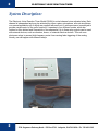
Model 63040A
User’s Manual
Model 63040A
ELECTRONIC VOICE
REACTION TIMER
USER’S MANUAL
3700 Sagamore Parkway North
P.O. Box 5729 • Lafayette, IN 47903 USA
Tel: 765.423.1505 • 800.428.7545
Fax: 765.423.4111
E-mail: [email protected]
www.lafayetteinstrument.com
© 2003 by Lafayette Instrument Company, Inc. All Rights Reserved-Rel.
Fax: 765-423-4111 . www.lafayetteinstrument.com . E-mail: [email protected]
3.10.03
2
ELECTRONIC VOICE REACTION TIMER
System Description:
The Electronic Voice Reaction Timer Model 63040A is a dual channel voice activated relay. Each
channel is independent and may be activated by either a piezo microphone, a throat microphone,
or a manual pushbutton all of which are supplied with each unit. A microprocessor is employed to
provide overall control of the unit's functions. It operates in four different modes, which are
Latched or Non-latched and Sequential or Non-sequential. Up to three relay outputs can be used
with external devices, such as counters, timers, or external stimulus devices. This unit uses
photomos relays to prevent high frequency noise from causing false triggering of the analog
circuitry, as can happen with solenoid relays.
2
3700 Sagamore Parkway North . PO Box 5729 . Lafayette, IN 47903 USA . Ph: 765-423-1505
Model 63040A
User’s Manual
3
User Instructions:
1. Plug the 12 Volt wall mount powerpack into Model 63040A and into an AC socket.
2. Plug a microphone into mic 1 input, and another microphone or hand-held switch into the mic 2
input. Turn the microphones on.
3. Turn unit on, and wait for initial messages to cycle on the LCD display.
4. The next message to be displayed will be the following;
LATCH MODE?
YES NO
When in the latch mode, the relay contacts will close upon receiving an input from the
corresponding microphone channel, and the relay will remain closed until manually reset by the
user. Choose the mode desired by pressing the button directly beneath the choices; Yes or No.
If the Non-latched mode is selected, a microphone trigger will cause a momentary closure of the
relay contacts. The closure time is determined by the amount of delay that is selected. The range
for delay is from 0 - 2 seconds, selectable in 10 millisecond increments. This is further described
in Non-latching/Sequential Mode, instruction # 6 (pg. 5).
5. Once the type of latching mode is determined, the next message to be displayed will be the
following;
SEQUENTIAL MODE?
YES NO
When in Sequential mode, microphone 1 must cause a trigger input before the unit will accept any
input from microphone 2. Again, the mode is chosen by pressing the button that is directly below
the choices given, YES or NO. In non-sequential mode, an input on either microphone will cause
the corresponding relay to close.
6. Once the choice is made for the sequential mode, the unit will be in one of four modes of
operation; 1) Latching/Sequential Mode, 2) Latching/Non-sequential Mode, 3) Non-latching/
Sequential Mode, or 4) Non-latching/Non-sequential Mode. The microphone sensitivity is set to a
default value of 25%, and the relay-on delay is set at 0.50 seconds. These settings can be
changed, and once changed, they will remain at the new settings until they are changed again by
the user, no matter if the mode of operation is changed. However, if power is interrupted to the
unit, the settings will go back to the default values.
Fax: 765-423-4111 . www.lafayetteinstrument.com . E-mail: [email protected]
3
4
ELECTRONIC VOICE REACTION TIMER
Latching/Sequential Mode
1. If the Latching/Sequential Mode is selected the next message to be displayed is the following;
VOL QUIT RUN
If the microphone sensitivity settings are to be changed, the button directly under the VOL should
be pressed. If you wish to leave this mode, press the button under QUIT. If the mode and settings
are satisfactory, and you wish to begin testing, press the button under RUN.
2. If the sensitivity is to be adjusted, the following screen will appear on the display;
PICK MICROPHONE
MIC1 MIC2 OK
Select the microphone that you wish to adjust by pressing the button underneath MIC 1 or MIC 2.
This will bring up a new screen in which the current sensitivity setting is displayed in percentage
of maximum sensitivity and the following choices will be displayed;
INC DEC OK
Pressing the INC button will increment the sensitivity in 1% increments. If the button is held down,
the sensitivity will increment at a moderate rate for the first five increments, and then will
increment at a much faster rate, until the button is released. The same is true for the DEC button,
except that the sensitivity will decrement. Once the sensitivity setting for that microphone is at the
desired value pressing the OK button will bring you back to the PICK MICROPHONE screen.
Pressing the OK button will take the user back to the previous screen.
3. If all the settings are acceptable, pressing the RUN button will allow testing to begin. The LCD
displays the following screen;
REAC TIME=0.000S
VOL QUIT
At this point, a trigger input from microphone 1 will cause four things to occur. First, Relay 1
contacts will close and latch and the green indicator LED for input mic 1 will turn on. At the same
time, Relay 3 contacts will close and the reaction time display will start running. Pressing the
QUIT button at this point will open relay 1 and 3 contacts, shut off the green LED, and reset the
clock. If the QUIT button is not pressed, the clock will continue to run until a input mic 2 trigger is
received. At this point, Relay 2 contacts will close latch while Relay 3 contacts open and the clock
display stops running. Again, pressing the QUIT button at this point, will open all closed relays,
turn off the indicator LEDs, and reset the clock display. If the QUIT button is pressed again, you
will leave this mode of operation, and be taken back to the latch mode selection screen.
4. When in this mode, the microphone sensitivity can still be adjusted, but only when no relays are
closed. Once a relay closes, the QUIT (reset) button must be pressed before sensitivity
adjustments can be made.
4
3700 Sagamore Parkway North . PO Box 5729 . Lafayette, IN 47903 USA . Ph: 765-423-1505
Model 63040A
User’s Manual
5
Latching/Non-sequential Mode
1.
In this mode of operation, the displays are the same as the Latching/Sequential Mode, and the
unit operates in almost the same manner. The main difference is that either input mic 1 or mic 2
can initiate the reaction timing sequence of closing Relay 3 contacts and starting the clock
display. Mic 1 trigger still latches Relay 1 and a Mic 2 trigger still latches Relay 2.
2.
Relay 3 closes when the first microphone trigger occurs and opens upon the reception of the
second trigger on the other microphone.
Non-latching/Sequential Mode
1.
When the Non-latching/Sequential Mode is selected the display will read the following;
TESTING
VOL DLY QUIT
2.
At this point, testing can immediately begin. Since this is a sequential mode of operation,
microphone 1 must produce a trigger input before microphone 2's input will become valid.
If microphone 1 has produced a trigger, and microphone 2 has not produced a trigger, the unit
will ignore microphone 1's inputs until microphone 2 has produced a trigger input.
3.
Once triggered, the corresponding relay will close for the amount of time determined delay.
4.
The microphone sensitivity levels can be changed at any time by pressing the VOL button and
following the procedure that was outlined in Latching/Sequential Mode, instruction # 2 (pg. 4).
5.
If the delay is to be adjusted, the user is to push the button underneath DLY on the display.
The next screen will display the following;
SELECT RELAY
RLY1 RLY2
OK
Pressing the OK button will bring you back to the testing mode. Pressing RLY1 button will allow
the user to adjust the "relay close" period for Relay 1. Pressing the RLY2 button is for adjusting
this time for Relay 2.
Fax: 765-423-4111 . www.lafayetteinstrument.com . E-mail: [email protected]
5
6
ELECTRONIC VOICE REACTION TIMER
Regardless of which relay is chosen to be adjusted, the next screen to appear on the LCD is
the following;
DELAY = 0.500S
INC DEC OK
6.
The delay period can now be incremented in 10 millisecond steps by pressing the INC button.
The maximum delay is 2.000 seconds. Conversely, the delay period can be decremented in 10
millisecond steps by pressing the DEC button. The minimum delay is 0.000 seconds. When
the delay is set to the desired period, pressing the OK button will bring the user back to the
previous screen, where the other relay may be selected for adjustment or the OK button can be
pressed and testing may begin. When the INC or DEC button is pressed and held, the delay
value will change at a moderate rate for the first five values and then change at a much faster
rate until the button is released.
7.
In this mode of operation Relay 3 is not used.
8.
Pressing the Quit button will cause the unit to exit this mode and return to the main
configuration selection screen.
Non-latching/Non-sequential Mode
1.
When in this mode of operation any trigger input from either microphone will cause it's
corresponding relay to close for the time determined by the delay period.
2.
The same testing screen as for the Non-latching/Sequential Mode is displayed and the
selection menu responds in the same manner.
6
3700 Sagamore Parkway North . PO Box 5729 . Lafayette, IN 47903 USA . Ph: 765-423-1505
Model 63040A
User’s Manual
7
System Specifications:
Power Supply:
12VDC
Power Consumption:
0.75W
Frequency Response:
50 - 7000Hz @ 10mVRMS
Sensitivity:
4.0mV
Output:
3 sets of NO Contacts
Contact Rating:
1.0A @ 200V AC/DC
Fax: 765-423-4111 . www.lafayetteinstrument.com . E-mail: [email protected]
7
ELECTRONIC
VOICE
REACTION
TIMER
ELECTRONIC
VOICE
REACTION
TIMER
Model 63040A
User’s Manual
Ordering Information:
All phone orders must be accompanied by a hard copy of
your order. All must include the following information:
1) Complete billing and shipping addresses
2) Name and department of end user
3) Model number and description of desired item(s)
4) Quantity of each item desired
5) Purchase order number or method of payment
6) Telephone number
DOMESTIC TERMS
There is a $50 minimum order. Open accounts can be extended
to most recognized educational institutions, hospitals and
government agencies. Net amount due 30 days from the date
of shipment. Enclose payment with the order; charge with
VISA, MasterCard, American Express; or pay COD. We must
have a hard copy of your order by mail or fax. Students,
individuals and private companies may call for a credit
application.
INTERNATIONAL PAYMENT INFORMATION
There is a $50 minimum order. Payment must be made in
advance by: draft drawn on a major US bank; wire transfer to
our account; charge with VISA, MasterCard, American
Express; or confirmed irrevocable letter of credit. Proforma
invoices will be provided upon request.
RETURNS
Equipment may not be returned without first receiving a Return
Goods Authorization Number (RGA).
When returning equipment for service, please call Lafayette
Instrument to receive a RGA number. Your RGA number will
be good for 30 days. Address the shipment to: Lafayette
Instrument Company, 3700 Sagamore Parkway North,
Lafayette, IN 47904, U.S.A. Shipments cannot be received at
the PO Box. The items should be packed well, insured for full
value, and returned along with a cover letter explaining the
malfunction. Please also state the name of the Lafayette
Instrument representative authorizing the return. An estimate
of repair will be given prior to completion ONLY if requested
in your enclosed cover letter. We must have a hard copy of
your purchase order by mail or fax, or repair work cannot
commence.
WARRANTY
Lafayette Instrument guarantees its equipment against all defects
in materials and workmanship to the ORIGINAL PURCHASER
for a period of one (1) year from the date of shipment, unless
otherwise stated. During this period, Lafayette Instrument will
repair or replace, at its option, any equipment found to be
defective in materials or workmanship. If a problem arises,
please contact our office for prior authorization before returning
the item. This warranty does not extend to damaged equipment
resulting from alteration, misuse, negligence or abuse, normal
wear or accident. In no event shall Lafayette Instrument be
liable for incidental or consequential damages. There are no
implied warranties or merchantability of fitness for a particular
use, or of any other nature. Warranty period for repairs or
used equipment purchased from Lafayette Instrument is 90 days.
DAMAGED GOODS
Damaged equipment should not be returned to Lafayette
Instrument prior to thorough inspection.
When a shipment arrives damaged, note damage on delivery
bill and have the driver sign it to acknowledge the damage.
Contact the delivery service, and they will file an insurance
claim. When damage is not detected at the time of delivery,
contact the carrier and request an inspection within 10 days of
the original delivery. Please call the Lafayette Instrument
Customer Service Department for a return authorization for
repair or replacement of the damaged merchandise.
Lafayette Instrument Co. Europe
3700 Sagamore Parkway North
P.O. Box 5729 • Lafayette, IN 47903 USA
Tel: 765.423.1505 • 800.428.7545
Fax: 765.423.4111
E-mail: [email protected]
www.lafayetteinstrument.com
4 Park Road, Sileby,
Loughborough, Leics., LE12 7TJ. UK.
Tel: +44 (0)1509 817700
Fax: +44 (0)1509 817701
E-mail: [email protected]
3700 Sagamore Parkway North . PO Box 5729 . Lafayette, IN 47903 USA . Ph: 765-423-1505