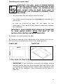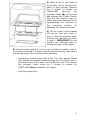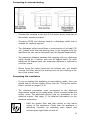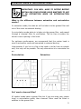
1
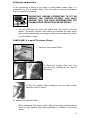
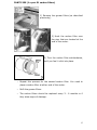
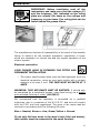
CAN52.4ME CAN75.3SS Canopy hood User Manual for your Baumatic CAN52.4ME 52 cm CAN75.3SS 75 cm Canopy Hood NOTE: This User Instruction Manual contains important information, including safety & installation points, which will enable you to get the most out of your appliance. Please keep it in a safe place so that it is easily available for future reference; for you or any person not familiar with the operation of the appliance. GS 03/09/13 2 Contents Page Environmental note 4 IMPORTANT SAFETY INFORMATION 5–7 Specifications of your cooker hood CAN52.4ME CAN75.3SS 8 – 10 8 9 - 10 Using your Baumatic cooker hood Before first use To use your cooker hood 10 - 11 10 10 - 11 Cleaning your Baumatic cooker hood General cleaning The grease filter 11 – 12 11 12 Maintenance Removing and cleaning the grease filter Changing a light bulb Fitting the carbon filters 12 – 15 12 13 14 - 15 Installation Electrical connection Before beginning installation Installing your cooker hood Connecting to external ducting 16 - 20 17 17 - 18 18 - 19 20 Extraction mode or recirculation mode? 21 - 22 Troubleshooting 22 – 23 Baumatic consumables 24 Contact details 27 3 ENVIRONMENTAL NOTE Note: Before discarding an old appliance, switch off and disconnect it from the power supply. Cut off and render any plug useless. Cut the cable off directly behind the appliance to prevent misuse. This should be undertaken by a competent person. o The packaging materials that Baumatic uses are environmentally friendly and can be recycled. o Please discard all packaging material with due regard for the environment. 4 IMPORTANT SAFETY INFORMATION Your safety is of the utmost importance to Baumatic. Please make sure that you read this instruction booklet before attempting to install or use the appliance. If you are unsure of any of the information contained in this booklet, please contact the Baumatic Customer Care Department. IMPORTANT: Any installation work must be carried out by a qualified electrician or competent person. o The hood must be installed in accordance with the installation instructions and all measurements followed. o If the cooker hood is installed for use above a gas appliance then the provision for ventilation must be in accordance with the Gas Safety Codes of Practice BS.6172, BS.5440 & BS.6891 (Natural Gas) and BS.5482 (LP Gas) 1994, the Gas Safety (Installation & Use) Regulations, the Building Regulations issued by the Department of the Environment, the Building Standards (Scotland) (Consolidated) Regulations issued by the Scottish Development Department. o It is dangerous to alter the specifications or to modify this product. Do not tamper with it or attempt to modify the appliance in any way. o When installing the hood, ensure that the following recommended distances are observed between the highest point on the hob top (including the burners) and the bottom of the cooker hood: Electric cookers: Gas cookers: Coal/ oil cookers: 700 mm 700 mm 800 mm IMPORTANT: DO NOT SET YOUR COOKER HOOD LESS THAN 700mm ABOVE YOUR COOKER. o When installed between adjoining wall cabinets, the cabinets must not overhang the hob. 5 o The edges of the cooker hood are sharp – be mindful of this as you handle your appliance, especially during installation and cleaning. DO NOT CLEAN IN BEHIND THE GREASE FILTERS! o If the room where the cooker hood is to be used contains a fuel burning appliance such as a central heating boiler then its flue must be of the sealed or balanced flue type. o If other types of flue or appliances are fitted, ensure that there is an adequate supply of air in the room. o When the hood is being used in its extractor function, ensure that the ducting is fire retardant and that there are no bends sharper than 90 degrees as this will reduce the efficiency of the hood. o Ensure the ducting for the extractor function has the same diameter as the outlet hole all the way through. o Keep young children from using, playing with or tampering with the cooker hood. Older children and infirm persons should be supervised if they are using the cooker hood. o Your cooker hood is for domestic use only. o Please dispose of the packing material carefully – children are especially vulnerable to it. o Dirty oil is an even greater fire risk. o Always put lids on pots and pans when cooking on a gas cooker. o The manufacturer refuses to accept any responsibility for damages arising to the hood or it catching on fire, from a failure to observe the fire safety advice contained in this instruction booklet. 6 o Remember that when in extraction mode, your cooker hood is removing air from your room. Ensure that proper ventilation measures are being observed. o Note that it removes odours from your room, not steam. o Warning - Always ensure that the cooker hood has been disconnected from the power supply before carrying out any work on the hood, including replacing light bulbs. o Do not connect the ducting system of this appliance to any existing ventilation system which is being used for any other purpose. o Do not install above a cooker with a high level grill. o Never leave frying pans unattended during use as overheated fats and oils might catch fire. o The cooker hood should not be exposed to a direct heat source from the cooking device underneath it, i.e. naked flame from a gas burner or heat from electric hob zones without a pan on them. o Do not attempt to use the cooker hood if it is damaged in any way. Never attempt to use it without the grease filters fitted or if the filters are excessively greasy! o Never flambé cook under this cooker hood. o The lights on this appliance should only be used during operation of the cooker hood. They should not be left on permanently and used as a lighting source. THE MANUFACTURER DECLINES ALL RESPONSIBILITY IN THE EVENT OF FAILURE TO OBSERVE THE INSTRUCTIONS GIVEN HERE, FOR INSTALLATION, MAINTENANCE AND SUITABLE USE OF THE HOOD. 7 Specifications of your cooker hood CAN52.4ME Product dimensions Height: Width: Depth: 162 mm 520 mm 296 mm Your canopy hood is fitted with: o o o o o o o Slider control operation Integrated axial motor 3 speeds 1 washable aluminium grease filter Non-return airflow flap 2 halogen lights Noise level: 45 / 50 / 55 dB Extraction capacity: 250 m³ / hr Optional extras: 1 pair ST1 carbon filters for air recirculation mode DK5 1 metre length ducting kit 125 mm Ø DK10 3 metre length ducting kit 125 mm Ø with flat channelling included. 8 CAN75.3SS Product dimensions Height: Width: Depth: 245 mm 740 mm 295 mm Your stainless steel canopy hood is fitted with: o o o o o o o Slider control operation Integrated axial motor 3 speeds 1 washable aluminium grease filter Non-return airflow flap 2 halogen lights Noise level: 61 / 65 / 68 dB Extraction capacity: 750 m³/hr Optional extras: 1 pair S1 Carbon filters for air recirculation mode DK5 1 metre length ducting kit 125 mm Ø DK10 3 metre length ducting kit 125 mm Ø with flat channelling included. All of the optional extras are available from the Baumatic Spares Department. 9 Using your Baumatic cooker hood Before first use IMPORTANT: THIS PROCESS MUST BE FOLLOWED BEFORE THE COOKER HOOD IS USED FOR THE FIRST TIME. o You should use a good quality stainless steel cleaner on ALL of the stainless steel areas of your cooker hood, before it is used for the first time. o This will help to leave a silicone water-resistant film to protect the stainless steel surfaces. To use your cooker hood o Make sure that it has been installed by a suitably qualified person, as per the information contained in Baumatic’s installation instructions. o Find the control panel, which is located at the front right of the canopy. o There are two sliders on the control panel, which perform separate functions. 1) Light control. The light can be used even when the motor is OFF. 0 = Light OFF 1 = Light ON 2) Motor speed control. = Low speed = Medium speed = High speed 10 IMPORTANT: IDEALLY YOU SHOULD SWITCH ON YOUR HOOD TEN MINUTES BEFORE YOU START TO COOK, OR AT THE VERY LEAST WHEN YOU BEGIN COOKING. YOU SHOULD ALSO RUN YOUR HOOD FOR TEN MINUTES AFTER YOU HAVE FINISHED COOKING. Cleaning your cooker hood IMPORTANT: BEFORE CLEANING, ALWAYS ENSURE THAT YOU HAVE SWITCHED YOUR COOKER HOOD OFF AT THE OMNI-POLAR SWITCH, SET AT THE WALL FROM THE CABLE. Cleaning o Clean the external parts of your cooker hood with mild liquid detergent and a new damp cloth. o Never use abrasive powder, corrosive solvents or brushes. o Never insert pointed objects into the motor’s protective grid. o Only clean the control panel and grease filter grill with mild liquid detergents and a new damp cloth. o If you are using the appliance in recirculation mode, then be sure to replace the carbon filters at the recommended interval (see section on “Fitting the carbon filter”). A build up of grease could cause a fire hazard. o Never attempt to clean the area above the grease filter. o IMPORTANT: You should regularly use a good quality stainless steel cleaner to maintain the shine and finish on the stainless steel areas of your cooker hood. o This will help to leave a silicone water-resistant film to protect the stainless steel surfaces and keep them in good condition for the life of the product. 11 The grease filter o Your cooker hood includes a grease filter which helps to absorb grease particles to protect your kitchen and furniture from greasy residues. o The metallic filter may become flammable if it becomes saturated with greasy residue. o To prevent this fire hazard, the filter should be cleaned regularly. Depending on use, this should be done every 10-15 days or at least once a month, using hot water and normal washing-up detergent. o DO NOT WASH THE GREASE FILTER IN A DISHWASHER. Maintenance Removing and cleaning the grease filter o First remove the grease filters by pulling down on the handle and pulling them away from the cooker hood. o Soak the grease filter in hot water and washing up liquid for about an hour. o Rinse it off thoroughly with hot water. o Repeat the process if required. o Refit the grease filter once it has dried. o IMPORTANT: Let the grease filter dry thoroughly before refitting it in the cooker hood. 12 Changing a light bulb IMPORTANT: BEFORE ATTEMPTING TO CHANGE A LIGHT BULB, YOU MUST ENSURE THAT YOU HAVE DISCONNECTED THE COOKER HOOD FROM YOUR MAINS SUPPLY. o Remove the grease filter (as described on page 12). o Prior to touching the light bulbs ensure that they have cooled down. o Find the bulb that requires replacement, you will find it located in the light fixture which is inside the exposed section of the canopy. o Press gently on the underside of the bulb that needs to be replaced and twist anticlockwise to release. o Insert a new identical 40W (max) bulb. o IMPORTANT: Defective bulbs should be replaced immediately. o If the lights still do not work, make sure that the bulbs are fitted properly into their housings before you call for technical assistance. o Refit the grease filter. 13 Fitting the carbon filter If the appliance is going to be used in recirculation mode then it is necessary to a fit a carbon filter. This will help to absorb unpleasant odours caused by cooking. IMPORTANT: BEFORE ATTEMPTING TO FIT OR REMOVE THE CARBON FILTERS, YOU MUST ENSURE THAT YOU HAVE DISCONNECTED THE COOKER HOOD FROM YOUR MAINS SUPPLY. o You will find that one filter will attach over the front of the fan motor. The active carbon filter must be replaced at least every four months depending on usage to allow normal operation when in recirculation mode. CAN52.4ME (1 x pair ST1 carbon filters) o Remove the grease filters. 2) Hook the carbon filter over the pins that are located at the end of the motor. 3) Turn the carbon filter clockwise until you feel it latch onto the motor’s sides. 4) Replace the grease filters. o When replacing the carbon filter, follow the steps outlined above and turn the carbon filter anti-clockwise to unlatch it from the motor. 14 CAN75.3SS (1 x pair S1 carbon filters) 1) Remove the grease filters (as described previously). 2) Hook the carbon filter over the pins that are located at the end of the motor. 3) Turn the carbon filter anticlockwise, until you feel it click into place. o Repeat this process for the second carbon filter. You need to place a carbon filter at either end of the motor. o Refit the grease filters. o The carbon filters should be replaced every 3 - 6 months or if they show signs of damage. 15 Installation IMPORTANT: Before installation read all the instructions and make sure that the voltage (V) and the frequency (Hz) indicated on the rating plate are exactly the same as the voltage and frequency in your home. The rating plate can be found behind the grease filters. The manufacturer declines all responsibility in the event of the installer failing to observe all the accident prevention regulations in force, which are necessary for normal use and the regular operation of the electric system. Electrical connection YOUR COOKER HOOD IS INTENDED FOR FITTED AND PERMANENT INSTALLATION. o The cooker hood’s power cable must be fitted upstream from the electrical connection, using an omni-polar switch with a contact distance of at least 3 mm. THE FUSE MUST BE RATED AT 3 AMPS. WARNING: THIS APPLIANCE MUST BE EARTHED. It should only be connected by a competent person, using fixed wiring via a double pole switched fused spur outlet. (UK ONLY). We recommend that the appliance is connected by a qualified electrician, who is a member of the N.I.C.E.I.C. and who will comply with the I.E.E. and local regulations. The wires in the mains lead are coloured in accordance with the following UK code: Blue = Neutral, Brown = Live, Green/Yellow = Ground If you only find two wires in the main’s lead (blue and brown), then neither must be connected to the earth terminal. 16 o As the colours of the wires in the appliance’s mains lead may not correspond with the coloured markings identifying the terminals in your spur box, please proceed as follows: o The blue wire must be connected to the terminal marked “N” (neutral), or coloured black. o The brown wire must be connected to the terminal marked “L” (live), or coloured red. Before beginning installation o Check that the product purchased is of a suitable size for the chosen installation area. In addition check whether there is an electrical socket available that will be accessible once the hood is mounted. If the product is going to be used in extraction mode, then there should also be space to connect a ducting hose to the outside. o Carry out all necessary masonry work prior to the fitting of the cooker hood. o Ensure that all electrical connections are carried out by a suitably qualified person. o Before commencing installation of the cooker hood the grease filter should be removed. o Check inside the product and ensure that there is no transit packaging or any other materials, such as packets of screws, guarantees etc. These should be removed and kept for future use. o If possible, disconnect and move freestanding or slot-in cookers from their position, to provide easier access to the rear wall and ceiling. If this is not possible, then a thick, protective covering should be placed over the worktop, hob top or cooker. This will help to protect these surfaces from damage and debris. o Select a flat surface for assembling the cooker hood. Cover that surface with a protective covering and place all cooker hood parts and fittings on it. o Do not tile, grout or silicone this appliance to the wall or cabinetry. This appliance is designed to be surface mounted only. 17 Installing your cooker hood IMPORTANT: YOU WILL HAVE TO DECIDE BEFORE INSTALLING YOUR COOKER HOOD WHETHER TO USE IT IN EXTRACTION MODE OR RECIRCULATION MODE. PLEASE TURN TO PAGE 21-22 NOW TO UNDERSTAND THE DIFFERENCES BETWEEN THESE TWO MODES. o We recommend that two people install this hood. o Your cooker hood should only be fitted into the underside of a kitchen unit. o It must be positioned at least 700 mm above the hob underneath it. You cannot fit this product by securing it between two cupboards. IMPORTANT: YOUR COOKER HOOD SHOULD BE CONNECTED TO YOUR MAINS SUPPLY AFTER THE REST OF THE INSTALLATION PROCESS HAS BEEN COMPLETED. 1) Remove the metal grease filter (A). 2) Create an opening in the underneath of the kitchen unit; the cutout must be of the dimensions shown in the drawing below. CAN52.4ME CAN75.3SS o IMPORTANT: If you are going to connect your cooker hood to external ducting, then you must complete the steps listed in the “Connecting to external ducting” section before carrying on with the rest of the installation (this information can be found on page 20). 18 3) Make a hole in the inside of the kitchen unit for the electrical cable to feed through. Remove the 2 screws (4 screws for CAN52.4ME) securing the extractor frame (B) to the hood and unscrew the 2 lights. Ensure that the two support clips on either side of the hood are set to accommodate the thickness of the mounting surface, by adjusting the clip via the screw. 4) Lift the cooker hood towards the cut-out that you made in step 2. Feed the electrical cable through the hole that you made in step 3. IMPORTANT: Do not connect the electrical cable to the mains supply at this stage. 5) Lift the cooker hood fully into the cut out that you made in step 2. If you are connecting the cooker hood to external ducting, then secure the ducting hose to the coupling on the appliance. o One person should support the hood. The other person should fully tighten the support screws through the pre-drilled holes in the outer frame of the hood, into the kitchen unit. Then replace the extractor frame using the 2 screws (4 screws for CAN52.4ME) (B) and reattach the 2 lights. o Refit the grease filter. 19 Connecting to external ducting o Connect the coupling to the top of the cooker hood, using two of the smaller screws provided. o Connect a Ø125 mm ducting hose to a discharge outlet that is suitable for cooking vapours. o The discharge outlet should have a cross section of at least 150 cm² (please note that the ducting hose is not supplied with the appliance but one can be obtained from the Spares Department). o The maximum distance between the coupling and your discharge outlet should be 3 metres, with one 90 degree bend. For each additional 90 degree bend, the maximum distance is reduced by a further metre. o Before fixing the cooker hood into the kitchen unit, you should connect the other end of the ducting hose to the coupling in the top of the cooker hood. Completing the installation o If you are setting the appliance to recirculation mode, then you should now fit the two carbon filters. See the “Fitting the carbon filters” section on pages 14-16. o The electrical connection must correspond to the electrical requirement noted on the rating plate, which is placed inside the cooker hood. The appliance should now be connected to the electrical supply. See page 17 for detailed information on the electrical connection. o Refit the grease filter and then switch on the mains supply to the appliance. Check that the appliance is operating correctly by selecting each speed and switching the light bulbs on and off. 20 Extraction mode or recirculation mode? IMPORTANT: YOU WILL HAVE TO DECIDE BEFORE INSTALLING YOUR COOKER HOOD WHETHER TO USE IT IN EXTRACTION MODE OR RECIRCULATION MODE. What is the difference between extraction and recirculation modes? In extraction mode, the stale air will be taken via the grease filter and out of the room via external ducting. In recirculation mode stale air is taken via the grease filter, and passed through a charcoal filter for purification. The air then re-enters the kitchen via an opening in the hood. For optimum performance, we recommend that the cooker hood is used in extraction mode and connected to external ducting. Unfortunately if you live in a flat or the hood is too far from an outside wall, this may not be possible. The only alternative is to recirculate the air. Recirculation: Extraction: Do I need a charcoal filter? All cooker hoods have a grease filter but if you are using your cooker hood in recirculation mode, then charcoal filters must be fitted in addition to the grease filter. 21 Troubleshooting IMPORTANT: If your cooker hood appears not to be operating properly, before contacting the Customer Care Department, please refer to the table below. My cooker hood will not start. o Check that the hood is connected to the power supply and whether you have selected any of the fan speeds. My cooker hood is not working effectively. o Check that fan speed is set to an appropriate setting. o Check that the grease filter is not dirty and if it requires cleaning. o If the hood is set up for recirculation mode, check that the carbon filters do not need to be replaced. o If the hood is set up for extraction mode, check that the ducting hose and discharge outlet are not blocked. My cooker hood is noisy and/or vibrating. o Check whether the installation has been completed as per the instruction booklet. o It is normal to get a certain amount of noise and vibration, due to the extraction capacity of the cooker hood. DO NOT MAKE ANY ATTEMPT TO REPAIR THE APPLIANCE YOURSELF. IF THE APPLIANCE IS STILL NOT OPERATING CORRECTLY, PLEASE CONTACT THE CUSTOMER CARE DEPARTMENT ON TELEPHONE NUMBER (0118) 933 6911. 22 My appliance isn’t working correctly IMPORTANT: If your appliance appears not to be operating correctly, then you should disconnect it from your mains supply and then contact Baumatic Customer Care on telephone number (0118) 933 6911. DO NOT ATTEMPT TO REPAIR THE APPLIANCE YOURSELF. Please note that if an engineer is asked to attend whilst the product is under guarantee and finds that the problem is not the result of an appliance fault, then you may be liable for the cost of the call out charge. The appliance must be accessible for the engineer to perform any necessary repair. If your appliance is installed in such a way that an engineer is concerned that damage will be caused to the appliance or your kitchen, then they will not complete a repair. This includes situations where appliances have been tiled in, sealed in with sealant, have wooden obstructions placed in front of the appliance, like plinths. Or any installation other than the one specified by Baumatic Ltd. has been completed. Please refer to the conditions of guarantee that appear on the warranty card that you receive with the appliance. IMPORTANT: Baumatic Ltd. operates a policy of continuous improvement and reserves the right to adjust and modify its products without prior notification. 23 Baumatic consumables o BC001 Degreaser for Dishwashers (200g) o BC002 Descaler for Washing Machines and Dishwashers (200g) o BC003 Ceramic Hob Cleaner (250ml) o BC004 Oven Cleaner (250ml) o BC005 Stainless Steel Cleaner and Protector (250ml) o BC007 E-Cloth – General Purpose Cloth o BC008 Microwave Cover To order a Baumatic consumable product please call 0123 5437 244 and quote the product code. You can also order online from eshop.baumatic.co.uk 24 25 26 Czech Republic/Slovakia Baumatic s.r.o. United Kingdom Baumatic Ltd., Baumatic Buildings, 6 Bennet Road, Reading, Berkshire RG2 0QX United Kingdom Lípová 665/1 460 01 Liberec 4 Czech Republic Panenská 34 811 03 Bratislava - Staré Mesto Slovakia Sales Telephone (0118) 933 6900 Sales Fax (0118) 931 0035 Customer Care Telephone (0118) 933 6911 Customer Care Fax (0118) 986 9124 Spares Telephone (01235) 437244 Advice Line Telephone (0118) 933 6933 +420 483 577 200 (CZ) +421 255 640 618 (SK) www.baumatic.cz www.baumatic.sk Germany Kundendienst & Ersatzteile Deutschland 0049(0)180-5888975 Oesterreich +43 (0) 820 / 420423 E-mail: [email protected] [email protected] [email protected] [email protected] www.baumatic.de Italy Baumatic Italia S.R.L. Via Galvani N.3 35011 Campodarsego (PD) Website: www.baumatic.co.uk +3904 9920 2297 www.baumatic.it Facebook: www.facebook.com/baumatic.uk Holland Baumatic Benelux B.V. Dukdalfweg 15d 1332 BH ALMERE Nederland Republic of Ireland Service Telephone 1-890 812 724 Spares Telephone 091 756 771 +31(0)36 549 1553/1555 www.baumatic.nl 27 28