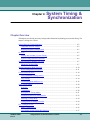
Download Technical Reference Guide
Transcript
Xedge 6000 TM 7HFKQLFDO#5HIHUHQFH#*XLGH for Switch Software Version 6.2.0 032R310-V620 Issue 2 October 2006 The Best Connections in the Business Copyright ©2006 General DataComm, Inc. ALL RIGHTS RESERVED. This publication and the software it describes contain proprietary and confidential information. No part of this document may be copied, photocopied, reproduced, translated or reduced to any electronic or machine-readable format without prior written permission of General DataComm, Inc. The information in this document is subject to change without notice. General DataComm assumes no responsibility for any damages arising from the use of this document, including but not limited to, lost revenue, lost data, claims by third parties, or other damages. If you have comments or suggestions concerning this manual, please contact: General DataComm, Inc. Technical Publications 6 Rubber Avenue, Naugatuck, Connecticut USA 06770 Telephone: 1 203 729 0271 Trademarks All brand or product names are trademarks or registered trademarks of their respective companies or organizations. Documentation Revision History of GDC P/N 032R310-000 Issue Date Description of Change 1 April 2005 Initial Release. 2 October 2006 Updated front matter, minor corrections. Related Publications Description Part Number Xedge 6000 Switch Application Guide 032R300-V620 Xedge 6000 Switch Technical Reference Guide 032R310-V620 Xedge 6000 Switch Software Ver 6.2.0 Configuration Guide Xedge 6000 Switch Software Ver 6.2.0 Release Notes 032R400-V620 032R901-V620 Xedge 6000 Switch Software Ver 7.X Configuration Guide (ISG2, PCx, OC-N LIM only) Xedge 6000 Switch Software Ver 7.X Release Notes 032R401-V7XX 032R901-V7XX Xedge 6000 Switch Chassis Installation Guide (all models) 032R410-000 Xedge 6000 Switch Hardware Installation Manual 032R440-V620 Xedge 6000 Switch Diagnostics Guide 032R500-V620 ProSphere NMS User Manual (AES, GFM, SPM, MV/S) ProSphere Routing Manager Installation and Operation Manual (RTM, INM, ADM) ProSphere Release Notes 032R610-VREV 032R600-VREV 032R906-VREV -REV is the hardware revision (-000, -001, etc.) -VREF is the most current software version (-V500, V620, V710, etc.) In addition to the publications listed above, always read Release Notes supplied with your products. Table of Contents Table of Contents Preface Manual Organization .........................................................................................................vii Support Services and Training................................................................................................viii Corporate Client Services.................................................................................................viii Factory Direct Support & Repair .....................................................................................viii Contact Information .........................................................................................................viii Chapter 1: Switch Function Overview.................................................................................................................................1-3 Xedge ATM Cell Processing............................................................................................1-4 Protocol Support...............................................................................................................1-4 Physical Layer.........................................................................................................................1-5 Physical Medium Dependent (PMD) Sub-layer...............................................................1-5 Transmission Convergence (TC) Sub-layer .....................................................................1-5 Transmission Frames........................................................................................................1-7 PDH Framing ..........................................................................................................................1-9 Physical Layer Convergence Protocol (PLCP) ................................................................1-9 DS1 Framing (1.544 Mbits/sec.) ......................................................................................1-9 E1 Framing (2.048 Mbits/sec.).......................................................................................1-14 E3 Framing (34.368 Mbit/sec.) ......................................................................................1-16 DS3 Framing (44.736 Mbit/sec.)....................................................................................1-17 SDH Transmission Frames ...................................................................................................1-20 SDH and SONET ...........................................................................................................1-20 SONET Equipment and Headers....................................................................................1-20 SONET Optical Interface Layers ...................................................................................1-21 SDH Framing..................................................................................................................1-23 Section Overhead............................................................................................................1-24 Line Overhead ................................................................................................................1-25 Path Overhead ................................................................................................................1-32 Direct Cell Transfer ..............................................................................................................1-34 TAXI (100 Mbits/sec.) ...................................................................................................1-34 HSSI (High-Speed Serial Interface) ...............................................................................1-34 ATM Layer ...........................................................................................................................1-35 ATM Cell Formats .........................................................................................................1-35 ATM Header Fields........................................................................................................1-35 ATM Adaptation Layer.........................................................................................................1-38 SDUs...............................................................................................................................1-38 032R310-V620 Issue 2 Xedge Switch Technical Reference Guide i Table of Contents Segmentation And Reassembly (SAR) sub-layer .......................................................... 1-38 Segmentation.................................................................................................................. 1-38 Convergence Sub-layer .................................................................................................. 1-38 AAL1 .................................................................................................................................... 1-39 AAL1 Convergence Sub-layer....................................................................................... 1-40 AAL1 SAR Sub-layer .................................................................................................... 1-40 Structured Data Transmission........................................................................................ 1-41 AAL1 Protocol Stack............................................................................................................ 1-44 AAL2 .................................................................................................................................... 1-47 Service Specific Convergence Sub-Layer...................................................................... 1-48 Common Part Sub-Layer (CPS)..................................................................................... 1-48 AAL5 .................................................................................................................................... 1-51 AAL5 CS Sub-layer ....................................................................................................... 1-52 AAL5 SAR Sub-layer .................................................................................................... 1-54 Frame Relay Protocol Stack ................................................................................................. 1-55 Generalized Frame Relay Protocol Stack Procedure ..................................................... 1-55 Frame Relay Frames ...................................................................................................... 1-57 Ethernet Protocol Stack ........................................................................................................ 1-59 Signaling............................................................................................................................... 1-62 Supported Signaling Protocols....................................................................................... 1-62 Signaling Channel .......................................................................................................... 1-63 Signaling Overview........................................................................................................ 1-63 Signaling Example ......................................................................................................... 1-65 SAAL.................................................................................................................................... 1-67 SAAL and Signaling ...................................................................................................... 1-67 SSCOP ........................................................................................................................... 1-68 Signaling Protocol Stack ...................................................................................................... 1-71 Chapter 2: Traffic Management Chapter Overview................................................................................................................... 2-1 Description.............................................................................................................................. 2-3 Congestion Management.................................................................................................. 2-3 Quality of Service (QoS) Classes..................................................................................... 2-3 Service Categories............................................................................................................ 2-4 Connection Admission Control .............................................................................................. 2-6 SVC/PVC Resources........................................................................................................ 2-6 CAC Bandwidth Managed on Egress (Backward) Links ................................................ 2-6 Bandwidth Checks ........................................................................................................... 2-6 Live Connection Bandwidth Resource Protection ........................................................... 2-6 Connection Admission Control Process .......................................................................... 2-6 ECC Traffic Management ...................................................................................................... 2-7 ii Xedge Switch Technical Reference Guide 032R310-V620 Issue 2 Table of Contents Buffer Management..........................................................................................................2-8 VPHs and OAM .............................................................................................................2-12 Handling of Existing VCs ..............................................................................................2-12 Routing VCs into a VPH ................................................................................................2-13 Multicast on a MTS ........................................................................................................2-13 Relationship between VPC Endpoints and Physical Links ............................................2-14 Relationship between VPC Endpoints and MSCC Logical Links .................................2-14 ECC Traffic Shaping.............................................................................................................2-17 Classical Shaping............................................................................................................2-17 Managed VP Services.....................................................................................................2-22 Service Category VP Queues .........................................................................................2-22 VPC Endpoint.................................................................................................................2-24 Multi-Tier Shaping (MTS) .............................................................................................2-26 ACP/ACS Traffic Management ............................................................................................2-29 PCR/SCR CAC...............................................................................................................2-29 Low Priority Overbooking .............................................................................................2-29 ACP/ACS Cell Flow.......................................................................................................2-32 Policing (Cell Controllers) ....................................................................................................2-36 Introduction ....................................................................................................................2-36 Supported Conformance Definitions..............................................................................2-37 Generic Cell Rate Algorithm (GCRA) ...........................................................................2-39 Bucket Status ..................................................................................................................2-40 Policing Configuration..........................................................................................................2-42 Bucket Variables ............................................................................................................2-42 Policing Expressions ......................................................................................................2-43 PCR and SCR Bucket Size .............................................................................................2-43 PVC Ingress and Egress .................................................................................................2-43 PVC Configuration Considerations................................................................................2-45 SPVC Bucket Configuration ..........................................................................................2-46 CDVT .............................................................................................................................2-47 Mode...............................................................................................................................2-47 Frame Traffic ........................................................................................................................2-49 Congestion .....................................................................................................................2-49 Network Congestion ....................................................................................................2-51 Frame Traffic Management ..................................................................................................2-52 Connection Admission Control .....................................................................................2-52 Traffic Policing...............................................................................................................2-52 Traffic Shaping ............................................................................................................2-55 Circuit Emulation Traffic......................................................................................................2-67 Peak Cell Rates (PCRs) for Structured Cell Formats Per VC .......................................2-67 032R310-V620 Issue 2 Xedge Switch Technical Reference Guide iii Table of Contents VPI/VCI Support............................................................................................................ 2-69 Ethernet Traffic..................................................................................................................... 2-70 Estimated Ethernet Throughput ..................................................................................... 2-70 Cells per Frame Calculation........................................................................................... 2-70 Frames per Second Calculation...................................................................................... 2-70 Peak Cell Rate Calculation ............................................................................................ 2-70 Chapter 3: Connections Chapter Overview................................................................................................................... 3-1 Connection Types ................................................................................................................... 3-3 Interswitch Signaling Protocols ....................................................................................... 3-3 Configuring Virtual SAPs for UNI 4.0 ............................................................................ 3-4 Switching Ranges............................................................................................................. 3-6 Permanent Connections .......................................................................................................... 3-8 PVCs ................................................................................................................................ 3-8 PVPs................................................................................................................................. 3-8 Multicast Connections .......................................................................................................... 3-11 Ingress Spatial Multicast................................................................................................ 3-12 Egress Spatial Multicast................................................................................................. 3-12 Egress Logical Multicast................................................................................................ 3-13 Switched Connections .......................................................................................................... 3-14 SPVCs ............................................................................................................................ 3-14 SPVPs............................................................................................................................. 3-15 SVCs .............................................................................................................................. 3-16 SAPs............................................................................................................................... 3-16 Internal NSAPs .............................................................................................................. 3-21 Addressing ..................................................................................................................... 3-22 Routing ................................................................................................................................. 3-26 Routing in the Switch..................................................................................................... 3-26 Distributed Routing Table.............................................................................................. 3-27 Using the Routing Table ................................................................................................ 3-28 Routing Table Directives ............................................................................................... 3-37 Re-routing SPVCs using DTLs ............................................................................................ 3-45 Operational Considerations............................................................................................ 3-45 Connecting ATM End Stations With SVCs ......................................................................... 3-47 Routing Tables ............................................................................................................... 3-47 PNNI.................................................................................................................................... 3-53 Overview........................................................................................................................ 3-53 Implementation .............................................................................................................. 3-55 PNNI Information Flow ................................................................................................. 3-58 iv Xedge Switch Technical Reference Guide 032R310-V620 Issue 2 Table of Contents PNNI Performance .........................................................................................................3-60 Multiple Signaling Control Channels ...................................................................................3-61 Logical SAPs ..................................................................................................................3-61 MSCC Applications........................................................................................................3-62 Chapter 4: System Timing & Synchronization General Network Timing Principles .......................................................................................4-2 Traditional Network Timing.............................................................................................4-2 Building Integrated Timing System .................................................................................4-4 Overview.................................................................................................................................4-5 Primary and Secondary System Timing ..........................................................................4-5 System Timing Reference Hierarchy ..............................................................................4-6 Timing Propagation Without The NTM .................................................................................4-7 Enhanced Clocking LIMs ................................................................................................4-8 Timing Propagation With The NTM ......................................................................................4-9 NTM Timing Fallback Sequence ...................................................................................4-10 Circuit Emulation Issues .......................................................................................................4-13 Circuit Emulation Timing (AAL1).................................................................................4-13 Loop Timing...................................................................................................................4-13 Clock Propagation and Recovery ...................................................................................4-14 Video Timing Modes ............................................................................................................4-17 Overview ......................................................................................................................4-17 Terminology ..................................................................................................................4-17 Description of Timing Modes ......................................................................................4-18 Automatic Selection of Timing Modes ........................................................................4-20 Selecting a Timing Mode .............................................................................................4-21 Timing Mode Switching Transients ...............................................................................4-21 ECC Timing Overview .........................................................................................................4-22 Master Timing Source ....................................................................................................4-23 Low Quality System Timing Bus (Driving)...................................................................4-24 Chapter 5: Network Management Chapter Overview ...................................................................................................................5-1 SNMP......................................................................................................................................5-2 Using SNMP.....................................................................................................................5-2 Using a Third-Party NMS .......................................................................................................5-3 Non-Standard Replies.......................................................................................................5-3 Xedge MIB .......................................................................................................................5-3 Loading MIBs into Third-Party Browsers........................................................................5-3 032R310-V620 Issue 2 Xedge Switch Technical Reference Guide v Table of Contents Viewing Xedge Traps in HP OpenView Alarms Browser .............................................. 5-5 Network Topology.................................................................................................................. 5-7 In-band Network Management............................................................................................... 5-9 MOLN.............................................................................................................................. 5-9 Tunnels........................................................................................................................... 5-11 Clusters........................................................................................................................... 5-11 Out-of-band Network Management...................................................................................... 5-13 Frame Relay Management ............................................................................................. 5-13 Ethernet/Router Management ........................................................................................ 5-15 Other Methods................................................................................................................ 5-15 IP Addressing Scheme.......................................................................................................... 5-16 Slot Controller IP Address ............................................................................................. 5-16 QEDOC IP Address ....................................................................................................... 5-16 IP Addresses In MOLN Configuration .......................................................................... 5-17 IP Addresses In Tunnel Configuration........................................................................... 5-17 IP Addresses In Cluster.................................................................................................. 5-18 Configuration of Management Workstations................................................................. 5-18 Management over ATM................................................................................................. 5-18 ATM Addressing and Call Routing...................................................................................... 5-19 ATM Addressing............................................................................................................ 5-19 Call Routing ................................................................................................................... 5-19 Routing in Large Networks............................................................................................ 5-20 Management Traffic Study................................................................................................... 5-23 Types of Traffic ............................................................................................................. 5-23 Flow Control of Management Traffic............................................................................ 5-24 Expected Traffic Profile/Load ....................................................................................... 5-24 Policing .......................................................................................................................... 5-25 Index vi Xedge Switch Technical Reference Guide 032R310-V620 Issue 2 Preface Scope of this Manual The Technical Reference Manual supports the Software Configuration and Operation Guide. It provides background information necessary to optimize the configuration of the Xedge switch and network. This information is intended for qualified service engineers who are experienced with electrical power distribution. Wiring must comply with the local electrical codes in your area that govern the installation of electronic equipment. The information contained in this manual has been carefully checked and is believed to be entirely reliable. As General DataComm improves the reliability, function, and design of their products, it is possible that the information in this document may not be current. Contact General DataComm, your sales representative or point your browser to http:\\www.gdc.com for the latest information on this and other General DataComm products. General DataComm, Inc. 6 Rubber Avenue Naugatuck, Connecticut 06770 U.S.A. Tel: 1 203 729-0271 Toll Free: 1 800 523-1737 Manual Organization This Technical Reference Manual is divided into five main chapters: Chapter 1: Switch Function Chapter 2: Traffic Management Chapter 3: Connections Chapter 4: System Timing & Synchronization Chapter 5: Network Management 032R310-V620 Issue 2 Xedge Switch Technical Reference Guide vii Preface Support Services and Training Support Services and Training General DataComm offers two comprehensive customer support organizations dedicated to pre-and post-sale support services and training for GDC products. Corporate Client Services and FactoryDirect Support & Repair assist customers throughout the world in the installation, management, maintenance and repair of GDC equipment. Located at GDC’s corporate facility in Naugatuck, Connecticut USA, these customer support organizations work to ensure that customers get maximum return on their investment through cost-effective and timely product support. Corporate Client Services Corporate Client Services is a technical support and services group that is available to GDC customers throughout the world for network service and support of their GDC products. Customers get the reliable support and training required for installation, management and maintenance of GDC equipment in their global data communication networks. Training courses are available at GDC corporate headquarters in Naugatuck, Connecticut, as well as at customer sites. Factory Direct Support & Repair GDC provides regular and warranty repair services through Factory Direct Support & Repair at its U.S. headquarters in Naugatuck, Connecticut. This customer support organization repairs and refurbishes GDC products, backed by the same engineering, documentation and support staff used to build and test the original product. Every product received for repair at Factory Direct Support & Repair is processed using the test fixtures and procedures specifically designed to confirm the functionality of all features and configurations available in the product. As part of GDC’s Factory Direct program, all product repairs incorporate the most recent changes and enhancements from GDC Engineering departments, assuring optimal performance when the customer puts the product back into service. Only GDC’s Factory Direct Support & Repair can provide this added value. Contact Information General DataComm, Inc. 6 Rubber Avenue Naugatuck, Connecticut 06770 USA Attention: Corporate Client Services General DataComm, Inc. 6 Rubber Avenue Naugatuck, Connecticut 06770 USA Attention: Factory Direct Support & Repair Telephones: 1 800 523-1737 1 203 729-0271 Fax: 1 203 729-3013 Email: [email protected] Telephones: 1 800 523-1737 1 203 729-0271 Fax: 1 203 729-7964 Email: [email protected] Hours of Operation: Monday - Friday 8:30 a.m. - 5:00 p.m. EST (excluding holidays) http://www.gdc.com viii Xedge Switch Technical Reference Guide 032R310-V620 Issue 2 Chapter 1: Switch Function Chapter Overview This chapter describes the function of the Xedge Switch. It is organized as follows: Overview.................................................................................................................................1-3 ACS Xedge ATM Cell Processing ...................................................................................1-4 Protocol Support...............................................................................................................1-4 Physical Layer.........................................................................................................................1-5 Physical Medium Dependent (PMD) Sub-layer...............................................................1-5 Transmission Convergence (TC) Sub-layer .....................................................................1-5 Transmission Frames........................................................................................................1-7 PDH Framing ..........................................................................................................................1-9 Physical Layer Convergence Protocol (PLCP) ................................................................1-9 DS1 Framing (1.544 Mbits/sec.) ......................................................................................1-9 E1 Framing (2.048 Mbits/sec.).......................................................................................1-14 E3 Framing (34.368 Mbit/sec.) ......................................................................................1-16 DS3 Framing (44.736 Mbit/sec.)....................................................................................1-17 SDH Transmission Frames ...................................................................................................1-20 SDH and SONET ...........................................................................................................1-20 SONET Equipment and Headers....................................................................................1-20 SONET Optical Interface Layers ...................................................................................1-21 SDH Framing..................................................................................................................1-23 Section Overhead............................................................................................................1-24 Line Overhead ................................................................................................................1-25 Path Overhead ................................................................................................................1-32 Direct Cell Transfer ..............................................................................................................1-34 TAXI (100 Mbits/sec.) ...................................................................................................1-34 HSSI (High-Speed Serial Interface) ...............................................................................1-34 ATM Layer ...........................................................................................................................1-35 ATM Cell Formats .........................................................................................................1-35 ATM Header Fields........................................................................................................1-35 ATM Adaptation Layer.........................................................................................................1-38 SDUs...............................................................................................................................1-38 Segmentation And Reassembly (SAR) sub-layer...........................................................1-38 Segmentation ..................................................................................................................1-38 032R310-V620 Issue 2 Xedge Switch Technical Reference Guide 1-1 Switch Function Convergence Sub-layer .................................................................................................. 1-38 AAL1 .................................................................................................................................... 1-39 AAL1 Convergence Sub-layer....................................................................................... 1-40 AAL1 SAR Sub-layer .................................................................................................... 1-40 Structured Data Transmission........................................................................................ 1-41 AAL1 Protocol Stack............................................................................................................ 1-44 AAL2 .................................................................................................................................... 1-47 Service Specific Convergence Sub-Layer...................................................................... 1-48 Common Part Sub-Layer (CPS)..................................................................................... 1-48 AAL5 .................................................................................................................................... 1-51 AAL5 CS Sub-layer ....................................................................................................... 1-52 AAL5 SAR Sub-layer .................................................................................................... 1-54 AAL5 SAR Sub-layer .................................................................................................... 1-54 Frame Relay Protocol Stack ................................................................................................. 1-55 Generalized Frame Relay Protocol Stack Procedure ..................................................... 1-55 Frame Relay Frames ...................................................................................................... 1-57 Ethernet Protocol Stack ........................................................................................................ 1-59 Signaling............................................................................................................................... 1-62 Supported Signaling Protocols....................................................................................... 1-62 Signaling Channel .......................................................................................................... 1-63 Signaling Overview........................................................................................................ 1-63 Signaling Example ......................................................................................................... 1-65 SAAL.................................................................................................................................... 1-67 SAAL and Signaling ...................................................................................................... 1-67 SSCOP ........................................................................................................................... 1-68 Signaling Protocol Stack ...................................................................................................... 1-71 1-2 Xedge Switch Technical Reference Guide 032R310-V620 Issue 2 Switch Function Overview Overview The Xedge Slot Controllers fall into two main categories: • Cell Controllers- These controllers process ATM cells for transport through the Xedge network. The Xedge Cell Controllers are responsible for ATM contract policing, queue management, and maintaining the separation between virtual connection service classes within the switch. • Adaptation Controllers - These specialized controllers process a specific form of traffic into ATM cells for transport through the network, then reassemble that traffic into its original state for delivery to its destination. In general, the switch works on three layers: • Physical Layer - The Physical Layer includes the line connections (T1, E1, OC3 etc.) and associated hardware such as LIMs (Line Interface Modules). • ATM Layer - The ATM Layer exists between the Slot Controller and the switch fabric. This layer is responsible for transporting ATM cells through the switch. • ATM Adaptation Layer (AAL) - One objective of the switch is to receive any form of traffic, segment that traffic into ATM cells for transfer through the system, then reassemble that traffic into its original state for delivery to its destination. This process can be called adaptation. The Adaptation Controllers use specific ATM Adaptation Layers for the various forms of traffic. The Xedge software architecture uses a process primarily based on the Protocol Reference Model shown in Figure 1-1. Plan C on trol P Lay l an e Ma na g em e er M nt a na g eme nt Use r Pla ne e High er L ayer s High er La ATM yers Ada ptat io n L ay ATM er Laye r Phy sica l Lay er Figure 1-1 Protocol Reference Model In figurative terms, the main Xedge protocol stack layers are: • Physical Layer • ATM Layer • ATM Adaptation Layer (AAL) • Signaling ATM Adaptation Layer (SAAL) • Application Layer 032R310-V620 Issue 2 Xedge Switch Technical Reference Guide 1-3 Switch Function Overview These layers and how they relate to the Xedge switch are discussed in this chapter. Xedge ATM Cell Processing For ATM applications, the Xedge Cell Controllers support the features necessary to implement a high-performance switched ATM backbone. The process of passing an ATM cell through the switch takes just a few microseconds and, in the distributed Xedge architecture, may occur simultaneously on all ATM modules. This provides high performance, scaleable, ATM cell switching. As an ATM cell enters the switch at a port, the controller verifies that the cell is error free, has a valid VPI/VCI value, and that the ATM connection indicated by the cell header has been defined within the switch. If these checks are successful, the cell passes to a traffic policing function that tests against the traffic contract defined for the connection. Xedge supports all of the options for the Generic Cell Rate Algorithm (GCRA, or leaky bucket) as defined in the ATM Forum User-toNetwork (UNI) 3.1 specification. Based on traffic parameters defined by the user, non-conforming cells can be optionally discarded or 'tagged' if they are outside of the contract defined for the ATM connection. Tagged cells then become eligible for discard if congestion is present elsewhere in the switch, or in the network. Protocol Support Each physical ATM interface in the switch is software selectable to support ATM Forum UNI 3.0 or 3.1, ATM Forum IISP (3.0/3.1), ATM Forum, and ACS NNI protocols. 1-4 Xedge Switch Technical Reference Guide 032R310-V620 Issue 2 Switch Function Physical Layer Physical Layer The ATM Physical Layer has two sub-layers: • the Physical Medium sub-layer • the Transmission Convergence sub-layer Physical Medium Dependent (PMD) Sub-layer The Physical Medium Dependent sub-layer is responsible for the correct transmission and reception of bits on the appropriate physical medium. Additionally it must reconstruct the proper bit timing for the receiver. The Physical Medium Dependent sub-layer consists of: • the Transmission Medium (Fiber, COAX, Twisted Pair) • Bit Timing and Line Coding Transmission Convergence (TC) Sub-layer Transmission Convergence is achieved in one of two ways: • mapping cells into transmission frames • transferring PLCP frames The TC sub-layer’s main functions are: • Cell Delineation • HEC (Header Error Control) generation/verification • Cell Rate Decoupling • Transmission Frame Adaptation • Transmission Frame Generation/Recovery The TC sub-layer receives bits from the PMD sub-layer and adapts them to the transmission system used (Synchronous Digital Hierarchy, Plesiochronous Digital Hierarchy, or Direct Cell transfer). It also generates the HEC for each cell at the transmitter as well as verifying the HEC (Header Error Control) at the receiver. Additionally Operations and Management (OAM) information is exchanged in the TC sub-layer. Header Error Control (HEC) HEC is a Cyclic Redundancy Check that is always carried in the fifth byte of the ATM cell. The TC calculates the checksum on the ATM cell’s header information (first 4-bytes) and places the result in the header’s fifth byte. HEC can correct a single bit error and detect multiple bit errors. Cells with multiple bit errors are discarded. The main purpose of HEC is to ensure that cells go to the correct destination. 032R310-V620 Issue 2 Xedge Switch Technical Reference Guide 1-5 Switch Function Physical Layer Cell Delineation Cell delineation is a process the Xedge Switch performs to identify the ATM cells in a flow of data. The delineation algorithm is based on the relationship between the ATM cell header bits and the HEC bits. The delineation algorithm has three main states: • Hunt State • Presync State • Synch State Figure 1-2 diagrams the cell delineation process. Arriving Data Hunt State Checks Bit by Bit Presumed Correct HEC Incorrect HEC Presync State Checks Cell by Cell Alpha Consecutive Incorrect HEC Delta Consecutive Correct HEC Synch State Departing ATM Cells Figure 1-2 Cell Delineation Diagram In the Hunt state the delineation process checks, bit by bit, for the HEC bits that match the ATM cell headers. Once it finds this relationship it can delineate the ATM cells and send this information to the Presync State. When the correct HEC is found by the Hunt state, the algorithm switches to the Presync State, which double-checks the HEC bits of the presumed correct ATM cells. If the Presync detects an error it returns the data to the Hunt State. If the Presync determines that the presumed ATM cells are correct it sends them to the Synch State. The Synch State is attained once the algorithm determines that the cells are correct for a specified number of times (Delta). At this point the system declares that it is synchronized. Xedge now knows where the ATM cells are in the data. The cells can now proceed through the Xedge system. The Synch State is lost when a specified number (Alpha) of consecutive cells have an incorrect HEC value. This causes the algorithm to return to the Hunt State. The ITU-T recommendation, with the SDH physical layer, for the Alpha value is 7 and the Delta value is 6. With the cell based physical layer, the ITU-T recommendation for the Alpha value is 7, and the Delta value is 8. 1-6 Xedge Switch Technical Reference Guide 032R310-V620 Issue 2 Switch Function Physical Layer Cell Payload Scrambling Cell Payload Scrambling is a process that scrambles the payload of an ATM cell so that it can be positively distinguished from the ATM cell header. Scrambling the ATM cell payload ensures that in a 5-byte sequence of data, the fifth byte is never equivalent to the HEC value for the preceeding 4-bytes. Scrambling the payload is used for HEC Delineation only. We recommend that you Scramble the payload when you configure a link for HEC Delineation. If you have a DS3 line, you will most likely use PLCP framing (to carry the 125µs clock) instead of HEC Delineation, therefore, we recommend that you do not use Scramble. When you use PLCP framing, Xedge finds the ATM cells based on the PLCP frame. Transmission Frames Pulse Code Modulation (PCM) When the analog signal is converted to digital, the information contained within the amplitude of a signal is converted to a number. This process is called quantization. This number is then encoded into bits for transmission. This process is called coding. The information is now contained within the bits, therefore the amplitude of the digital pulses can vary with no effect on the information. The circuit that translates the quantized signal is called an encoder (sometimes referred to as a coder). The circuit at the receiving end that performs the inverse operation (digital to analog) is called a decoder. The combination of the two circuits is called a CODEC (COder-DECoder). Time Division Multiplexing In order to transmit over a digital system, an analog signal (such as voice) must be digitized by an analog-to-digital converter. After the conversion the digitized signal can be transmitted in the form of digital pulses. These digital pulses can be shortened in time so that many of them can be transmitted by a single analog signal. This technique is referred to as Time Division Multiplexing (TDM). In Time Division Multiplexing, a multiplexed stream of bits is separated by the addition of framing information. Framing information enables the receiving end of the connection to identify the beginning of each frame. The framing information is typically a single bit (T1) or a code word consisting of 8-bits (E1). Analog-to-Digital Sampling Analog-to-digital sampling is used to adapt analog signals for transmission over a digital system. The amplitude of an analog signal does not vary much to either side of any one point of the signal in time. Thus, a sample of the signal at any instant in time is a close representation of the signal for a short period of time on either side of the sampling point. The Nyquist Criterion proves that if the signal is sampled at twice the highest frequency in the signal, the samples will contain all the information contained in the original signal. For a voice channel, the bandwidth is set at 4,000 Hz (4 kHz). According to the Nyquist Criterion, we must use a sampling rate of 8,000 samples per second (8 kHz) to carry a voice call intelligibly. Figure 1-3 is a simplified representation of this process. 032R310-V620 Issue 2 Xedge Switch Technical Reference Guide 1-7 Switch Function Physical Layer Sampled Values Analog Signal In Figure 1-3 1-8 Input Filter Sampler Band-Limited Input Transmitted Samples Output Filter Reconstructed Analog Signal Simplified Analog-to-Digital Sampling Diagram Xedge Switch Technical Reference Guide 032R310-V620 Issue 2 Switch Function PDH Framing PDH Framing The Plesiochronous Digital Hierarchy (PDH) describes the various bit rates defined by the ITU-T in 1972 for North America, Europe and Japan. ATM cells are transported in PDH frames according to the ITU-T Recommendation G.804. PDH includes the following Physical Layer interfaces used by Xedge: • DS1 (T1) • DS3 (T3) • E1 • E3 DS1, E1, and E3 are considered synchronous in that their line rates (by bits) are a multiple of 8kHz (125µs). This synchronization enables these interfaces to carry the 125µs reference clock across a transmission link. The DS3 is considered asynchronous in that its 44.736 Mbps interface is not a multiple of 8kHz thus it cannot itself carry the 125µs reference clock across a transmission link. To carry the reference clock the DS3 interface must use the ATM Physical Layer Convergence Protocol (PLCP). Physical Layer Convergence Protocol (PLCP) The Physical Layer Convergence Protocol (PLCP) was developed to transmit the data packets of Metropolitan Area Networks (MANs) on PDH lines. The transfer mechanism within MANs is Dual Queue Dual Bus (DQDB) which, like ATM, uses fixed 53-byte long cells. The transport protocol specified for MANs is SMDS (Switched Multi-megabit Data Service). This protocol is made up of three SIP (SMDS Interface Protocol) layers. SIP Layer-1 contains the transmission system and the physical layer. SIP Layer-2 contains the SIP PDU (Protocol Data Units) which are 53-bytes long. These SIP PDUs are accounted for in the PLCP frame. The PLCP frames are then transferred to the payload field of the PDH transmission frame. Since the length of an ATM cell is also 53-bytes (same as the SIP PDU), we can use the PLCP frame to transmit ATM cells over PDH lines. The obvious advantage is that we can transmit ATM cells over existing PDH lines. The disadvantage is that the ATM cell overhead of 5-bytes is added to the PLCP frame overhead as well as the PDH frame overhead. This decreases the available payload bandwidth by 9% as compared to direct cell mapping onto existing transmission frames. In order to maximize payload bandwidth efficiency, ATM cells are mapped into transmission frames using HEC (Header Error Control) delineation. Note that it is not possible to carry timing information in DS3 transmission frames without PLCP framing. DS1 Framing (1.544 Mbits/sec.) A common digital multiplexing system in the United States is T1 which consists of 24-channels (time slots) multiplexed over 4 wires (2-transmit, 2-receive). The format used to frame T1 transmitted data is called DS1. DS1 partitions data into 193 bit frames. The first bit of the frame is always the framing synchronization bit leaving 192 bits for the 24 channel data (8 bits per channel). The time duration for the frame is 125µs thus T1 must send or receive data at 1,544,000 bits per second (1.544 Mbps). Figure 1-4 is a graphical example of the DS1 frame format. 032R310-V620 Issue 2 Xedge Switch Technical Reference Guide 1-9 Switch Function PDH Framing Framing Bit CH 1 8 bits CH 2 8 bits Channels 7-21 CH 3 8 bits CH 4 8 bits CH 5 8 bits CH 6 8 bits CH 7 8 bits CH 22 8 bits CH 23 8 bits CH 24 8 bits 192 bit Data 193 bit Frame time = 125µs Figure 1-4 DS1 Frame Format DS1 PLCP Framing Note Due to overhead bandwidth consumption, ATM cells are rarely, if ever, mapped to DS1 PLCP frames. However, since it is possible to do so with the Xedge Switch, we provide this section on the DS1 PLCP for reference purposes. The DS1 PLCP (Physical Layer Convergence Protocol) is specified as ten 57-byte rows with the final row containing a 6-byte trailer (used for padding). The DS1 PLCP frame must have a 3-ms length and be transmitted at 1.536 Mbits/sec. (this is the exact payload bandwidth of a DS1 frame). The payload bandwidth for ATM cells when transmitted using DS1 PLCP frames is 1.280 Mbits/ sec. This yields a bandwidth efficiency of 83%. The overhead, containing the DS1, PLCP and ATM overheads, accounts for 17% of the effective transmission bandwidth. Path Overhead Bytes A1 A2 P9 Z4 L2_PDU A1 A2 P8 Z3 L2_PDU A1 A2 P7 Z2 L2_PDU A1 A2 P6 Z1 L2_PDU A1 A2 P5 F1 L2_PDU A1 A2 P4 B1 L2_PDU A1 A2 P5 X L2_PDU A1 A2 P3 G1 L2_PDU A1 A2 P2 M2 L2_PDU A1 A2 P1 M1 L2_PDU A1 A2 P0 C1 L2_PDU Figure 1-5 Trailer 6-bytes DS1 PLCP Frame (3 ms) Figure 1-6 illustrates the mapping of ATM cells into a DS1 Superframe using PLCP Framing. 1-10 Xedge Switch Technical Reference Guide 032R310-V620 Issue 2 Switch Function PDH Framing 5-byte ATM Cell Header ATM Cell Payload Figure 1-6 ATM Cell Payload A1 A2 P8 Z3 A1 A2 P9 Z4 M1 ATM Cell Payload C1 M2 ... ... ... Ten 53-byte ATM Cells Pad Bits One PLCP Superframe One DS1 Superframe ATM Cell Mapping to DS1 Superframe Using PLCP Figure 1-5 illustrates the DS1 PLCP frame. The A1 and A2 bytes in the DS1 PLCP frame are used to identify the start of each row. Bytes P0 through P9 are required to identify the path overhead bits (Z4 through C1). The Z4 through Z1 path overhead bytes are reserved for future use. Byte B1 holds a checksum (BIP-8: Bit-Interleaved Parity) for the 10 x 54-byte structure of the preceding PLCP frame (the 54-bytes account for the 53-byte cell plus the path overhead byte in each row). The G1 byte is used for the current transmission status and the signal reception quality (loss of signal, loss of synchronization, checksum error, etc.). The value of the Far End Block Error (FEBE) in this byte indicates the number of blocks with a checksum (BIP-8) error. In the event of synchronization loss, the Yellow Signal is set to one. The Link Signal Status (LSS) shows the link status (connected, signal not synchronous, no signal). The C1 byte holds the number of padding bytes in the trailer. As the trailer is always 6-bytes in the DS1 PLCP frame this byte is set to zero by default. The 6-bytes in the trailer always follow the bit pattern: 11001100. DS1 Channel Associated Signaling (CAS) In order to carry voice traffic signaling messages in structured data, DS1 uses a form of in-band Channel Associated Signaling (CAS) called “robbed bit signaling.” CAS forces (overwrites) the signaling bits into certain places in the structured data stream (Robbing). The effect of this loss of data bits on PCM voice is negligible. DS1 Superframes use the “A and B” signaling bits. CAS “robs” bit-8 in each DS0 (DS01-24) of frame-6 of the DS1 Superframe to carry the “A” signaling bit. CAS “robs” bit-8 in each DS0 (DS0124) of frame-12 of the DS1 Superframe to carry the “B” signaling bit. Figure 1-7 illustrates the DS1 Superframe and the “robbed bit signaling.” 032R310-V620 Issue 2 Xedge Switch Technical Reference Guide 1-11 Switch Function PDH Framing Frame 6 Frame 6 DS01-24 Frame 1 (125 µs) Frame 2 (125 µs) Frame 3 (125 µs) Frame 4 (125 µs) Frame 5 (125 µs) Frame 6 (125 µs) Frame 7 (125 µs) Frame 8 (125 µs) Frame 9 (125 µs) Frame 10 (125 µs) Frame 11 (125 µs) DS01 DS02 DS03 DS04 DS05 DS06 DS07 DS08 DS09 DS010 DS011 DS012 DS013 DS014 DS015 DS016 DS017 DS018 DS019 DS020 DS021 DS022 DS023 DS024 bit-1 bit-2 bit-3 bit-4 bit-5 bit-6 bit-7 A-bit “robbed bits” Frame 12 DS01-24 bit-1 bit-2 bit-3 bit-4 bit-5 bit-6 bit-7 B-bit Frame 12 (125 µs) Figure 1-7 Frame 12 DS01 DS02 DS03 DS04 DS05 DS06 DS07 DS08 DS09 DS010 DS011 DS012 DS013 DS014 DS015 DS016 DS017 DS018 DS019 DS020 DS021 DS022 DS023 DS024 DS1 Superframe with Robbed Bit Signaling DS1 Extended Superframes use the “A, B, C, and “D” signaling bits. CAS “robs” bit-8 in each DS0 (DS01-24) of frame-6 of the DS1 Extended Superframe to carry the “A” signaling bit. CAS “robs” bit-8 in each DS0 (DS01-24) in frame-12 of the DS1 Extended Superframe to carry the “B” signaling bit. CAS “robs” bit-8 in each DS0 (DS01-24) in frame-18 of the DS1 Extended Superframe to carry the “C” signaling bit. CAS “robs” bit-8 in each DS0 (DS01-24) in frame-24 of the DS1 Extended Superframe to carry the “D” signaling bit. Figure 1-8 illustrates the DS1 Extended Superframe and the “robbed signaling bits.” 1-12 Xedge Switch Technical Reference Guide 032R310-V620 Issue 2 Switch Function PDH Framing Frame 6 Frame 6 DS01-24 Frame 1 (125 µs) Frame 2 (125 µs) Frame 3 (125 µs) Frame 4 (125 µs) Frame 5 (125 µs) Frame 6 (125 µs) Frame 7 (125 µs) Frame 8 (125 µs) Frame 9 (125 µs) Frame 10 (125 µs) Frame 11 (125 µs) Frame 12 (125 µs) Frame 13 (125 µs) Frame 14 (125 µs) Frame 15 (125 µs) Frame 16 (125 µs) Frame 17 (125 µs) Frame 18 (125 µs) Frame 19 (125 µs) Frame 20 (125 µs) DS01 DS02 DS03 DS04 DS05 DS06 DS07 DS08 DS09 DS010 DS011 DS012 DS013 DS014 DS015 DS016 DS017 DS018 DS019 DS020 DS021 DS022 DS023 DS024 bit-1 bit-2 bit-3 bit-4 bit-5 bit-6 bit-7 A-bit “robbed bits” Frame 12 DS01-24 bit-1 bit-2 bit-3 bit-4 bit-5 bit-6 bit-7 B-bit Frame 12 DS01 DS02 DS03 DS04 DS05 DS06 DS07 DS08 DS09 DS010 DS011 DS012 DS013 DS014 DS015 DS016 DS017 DS018 DS019 DS020 DS021 DS022 DS023 DS024 Frame 21 (125 µs) Frame 22 (125 µs) Frame 18 DS01-24 Frame 24 (125 µs) bit-1 bit-2 bit-3 bit-4 bit-5 bit-6 bit-7 C-bit “robbed bits” Frame 24 DS01-24 bit-1 bit-2 bit-3 bit-4 bit-5 bit-6 bit-7 D-bit Figure 1-8 032R310-V620 Issue 2 DS1 Extended Superframe with Robbed Bit Signaling Xedge Switch Technical Reference Guide 1-13 Switch Function PDH Framing E1 Framing (2.048 Mbits/sec.) The E1 frame format is based on the CEPT (Conference of European Postal and Telecommunications) PCM-30 standard. This standard specifies a 32-word frame of 256 bits. These 256 bits include 8 bit words for 30 channels (240 bits) and two 8 bit framing words. The frame is arranged with the first word being an 8 bit framing word. It is followed by 8 bit data words for 15 channels. Following these 15 channels is an 8 bit signaling word that precedes the 8 bit words for the final 15 channels. The time duration for the frame is 125µs thus E1 must send or receive data at 2,048,000 bits per second (2.048 Mbps). Figure 1-9 is a graphical example of the E1 frame format. 8 Signaling or Data bits 8 Framing bits 8 bits CH 1 8 bits CH 2 8 bits (CH 16 if CAS is not enabled) CH 3 8 bits CH 14 8 bits CH 15 8 bits 8 bits CH 16 8 bits Channels 3-13 CH 29 8 bits CH 30 8 bit Channels 17-28 256 bit Frame time = 125µs Figure 1-9 E1 Frame Format E1 Channel Associated Signaling (CAS) To carry signaling messages in structured data, E1Channel Associated Signaling (CAS) uses Time Slot 16 (TS16) of each frame to carry the signaling bits. E1 uses TS0 of each frame to carry the Framing bits, thus the frame has 30 channels to carry voice and/or data. If CAS is not used, TS16 can carry data. In this case, TS16 becomes Channel 16, therefore the E1 frame has 31 channels. Figure 1-7 illustrates the E1 Multiframe Signaling bits (with CAS enabled). 1-14 Xedge Switch Technical Reference Guide 032R310-V620 Issue 2 Switch Function PDH Framing TS0 Frame 1 (125 µs) Frame 2 (125 µs) Frame 3 (125 µs) Frame 4 (125 µs) Frame 5 (125 µs) Frame 6 (125 µs) Frame 7 (125 µs) Frame 8 (125 µs) Frame 9 (125 µs) Frame 10 (125 µs) Frame 11 (125 µs) Frame 12 (125 µs) Frame 13 (125 µs) Frame 14 (125 µs) Frame 15 (125 µs) TS0 Channel1 (TS1) Channel2 (TS2) Channel3 (TS3) Channel4 (TS4) Channel5 (TS5) Channel6 (TS6) Channel7 (TS7) Channel8 (TS8) Channel9 (TS9) Channel10 (TS10) Channel11 (TS11) Channel12 (TS12) Channel13 (TS13) Channel14 (TS14) Channel15 (TS15) TS16 Channel16 (TS17) Channel17 (TS18) Channel18 TS19) Channel19 (TS20) Channel20 (TS21) Channel21 (TS22) Channel22 (TS23) Channel23 (TS24) Channel24 (TS25) Channel25 (TS26) Channel26 (TS27) Channel27 (TS28) Channel28 (TS29) Channel29 (TS30) Channel30 (TS31) bit-1 bit-2 bit-3 bit-4 bit-5 bit-6 bit-7 bit-8 Framing bits TS16 A-bit B-bit C-bit D-bit A-bit B-bit C-bit D-bit Signaling bits Figure 1-10 E1 Multiframe with Signaling Bits E1 PLCP Framing Due to overhead bandwidth consumption, ATM cells are rarely, if ever, mapped to E1 PLCP frames. However, since it is possible to do so with the Xedge Switch, we provide this section on the E1 PLCP for reference purposes. Note The E1 PLCP frame is specified as ten 57-byte rows, similar to the DS1 PLCP frame. Unlike the DS1 PLCP frame, the E1 PLCP frame does not require a trailer for padding. The 4560 E1 PLCP bits fit exactly into nineteen E1 transmission frames. The E1 PLCP frame is 2.375 ms long and transmits at a rate of 1.920 Mbits/sec. (this is the payload bandwidth of an E1 frame). 032R310-V620 Issue 2 Xedge Switch Technical Reference Guide 1-15 Switch Function PDH Framing Path Overhead Bytes A1 A2 P9 Z4 First DQDB slot (53-bytes) A1 A2 P8 Z3 DQDB slot (53-bytes) A1 A2 P7 Z2 DQDB slot (53-bytes) A1 A2 P6 Z1 DQDB slot (53-bytes) A1 A2 P5 F1 DQDB slot (53-bytes) A1 A2 P4 B1 DQDB slot (53-bytes) A1 A2 P5 X DQDB slot (53-bytes) A1 A2 P3 G1 DQDB slot (53-bytes) A1 A2 P2 M2 DQDB slot (53-bytes) A1 A2 P1 M1 DQDB slot (53-bytes) A1 A2 P0 C1 Last DQDB slot (53-bytes) Figure 1-11 E1 PLCP Frame (2.375 ms) Figure 1-9 illustrates the E1 PLCP frame. The A1 and A2 bytes in the E1 PLCP frame are used to identify the start of each row. Bytes P0 through P9 are required to identify the path overhead bits (Z4 through C1). The Z4 through Z1 path overhead bytes are reserved for future use. Byte B1 holds a checksum (BIP-8: Bit-Interleaved Parity) for the 10 x 54-byte structure of the preceeding PLCP frame (the 54-bytes account for the 53-byte cell plus the path overhead byte in each row). The G1 byte is used for the current transmission status and the signal reception quality (loss of signal, loss of synchronization, checksum error, etc.). The value of the Far End Block Error (FEBE) in this byte indicates the number of blocks with a checksum (BIP-8) error. In the event of synchronization loss, the Yellow Signal is set to one. The Link Signal Status (LSS) shows the link status (connected, signal not synchronous, no signal). E3 Framing (34.368 Mbit/sec.) To create the E3 frame, four E1 channels are first multiplexed into a single 8.448 Mbps E2 channel. Four E2 channels are then multiplexed into a single 33.368 Mbps E3 signal stream. Frequency deviations of the separate channels are compensated for by adding justification bits. When the channels are de-multiplexed, the justification bits are removed to restore the original channel frequency. The length of an E3 frame is 1536-bits, and consists of four sub-frames of 384-bits each. The first ten bits of the first sub-frame identify the start of the frame (frame alignment bits). The eleventh bit is used for the Remote Alarm Indication (RAI) and the twelfth bit is reserved for national purposes. The first four bits of the remaining three sub-frames are used to control frequency justification between the frequencies of the E2 channel and the E3 carrier frequency. Figure 1-12 is a graphical representation of the E3 frame. 1-16 Xedge Switch Technical Reference Guide 032R310-V620 Issue 2 Switch Function PDH Framing 1 1 1 1 0 C1 C1 C1 C1 Bits 5 - 384 C2 C2 C2 C2 Bits 5 - 384 C3 C3 C3 C3 St 1 St 0 St 0 0 0 RAI St Res Bits 13 - 384 Bits 9 - 384 Figure 1-12 E3 Frame E3 PLCP Framing Due to overhead bandwidth consumption, ATM cells are rarely, if ever, mapped to E3 PLCP frames. However, since it is possible to do so with the Xedge switch, we provide this section on the E3 PLCP for reference purposes. Note The E3 PLCP frame consists of nine 53-byte cells each preceded by four overhead bytes. The final cell has a 18 to 20 byte trailer used for padding. An E3 PLCP frame is roughly as long as three G.751 E3 transmission frames (each at 1536 bytes). Path Overhead Bytes A1 A2 P8 Z3 DQDB slot (53-bytes) A1 A2 P7 Z2 DQDB slot (53-bytes) A1 A2 P6 Z1 DQDB slot (53-bytes) A1 A2 P5 F1 DQDB slot (53-bytes) A1 A2 P4 B1 DQDB slot (53-bytes) A1 A2 P3 G1 DQDB slot (53-bytes) A1 A2 P2 M2 DQDB slot (53-bytes) A1 A2 P1 M1 DQDB slot (53-bytes) Trailer A1 A2 P0 C1 Last DQDB slot (53-bytes) 18 to 20 bytes Figure 1-13 E3 PLCP Frame (125 µs) DS3 Framing (44.736 Mbit/sec.) DS3 came about due to advances in hardware technology especially with optical fiber. We can trace DS3 back to the 1970s when DS2 was introduced. DS2 consisted of four DS1 channels that were bit-interleaved to form a single 6.312 Mbps circuit. Seven DS2 channels are then multiplexed producing one DS3 channel with a line rate of 44.736 Mbps. Figure 1-14 is a graphical representation of a DS3 frame that shows the sequential position of the DS3 overhead bits. 032R310-V620 Issue 2 Xedge Switch Technical Reference Guide 1-17 Switch Function Information X1 Payload Information X2 Payload Information P1 Payload Information P2 Payload Information M0 Payload Information M1 Payload Information M0 Payload PDH Framing Information F1 Payload Information F1 Payload Information F1 Payload Information Information F1 Payload Information F1 Payload Information F1 Payload C32 Payload Information Information F2 Payload C42 Payload Information Information F2 Payload C52 Payload Information Information F2 Payload C62 Payload Information Information Information C71 Payload Information Information Information C61 Payload C22 Payload F2 Payload Information C51 Payload Information Information Information C41 Payload C12 Payload F2 Payload Information C31 Payload F1 Payload F2 Payload Information C21 Payload Information Information Information C11 Payload F2 Payload C72 Payload Information F3 Payload Information F3 Payload Information F3 Payload Information F3 Payload Information F3 Payload Information F3 Payload Information F3 Payload Information C13 Payload Information C23 Payload Information C33 Payload Information C43 Payload Information C53 Payload Information C63 Payload Information C73 Payload Information F4 Payload Information F4 Payload Information F4 Payload Information F4 Payload Information F4 Payload Information F4 Payload Information F4 Payload Figure 1-14 DS3 Frame Table 1-1 Sequential Position of Overhead Bits X1 F1 C11 F2 C12 F3 C13 F4 X2 F1 C21 F2 C22 F3 C23 F4 P1 F1 C31 F2 C32 F3 C33 F4 P2 F1 C41 F2 C42 F3 C43 F4 M1 F1 C51 F2 C52 F3 C53 F4 M2 F1 C61 F2 C62 F3 C63 F4 M3 F1 C71 F2 C72 F3 C73 F4 The overhead bits are used as follows: • P - parity bits • F - used for M-Sub-frame Alignment • M - used for M-frame alignment • C - used for padding DS3 is roughly equivalent to 28 DS1 signals (672 individual channels) transmitted at 44.736 Mbps which equates to a nominal frame duration of 106.4µs. The DS3 signal consists of 699 octets (5592bits) per 125µs time period. The DS3 multiframe consists of 7 transmission frames that contain 680 bits each, for a total of 4760 bits (per DS3 multiframe). Each of these transmission frames holds 8 payload blocks of 85 bits each, 84 bits for payload and one bit for overhead (framing bits). Figure 1-15 illustrates the DS3 Multiframe and its first transmission frame. There are 4704 bits for payload data per DS3 frame which corresponds to a nominal payload rate of 44.210 Mbps. Each multiframe contains 56 bits of overhead. This leaves approximately 690.78 octets (5526.21-bits) available every 125µs for use by the DS3 PLCP. Note 1-18 Since the 44.210 Mbps payload is not a multiple of 8 kHz, DS3 must use DS3 PLCP framing in order to transmit the 125µs bit clock. Xedge Switch Technical Reference Guide 032R310-V620 Issue 2 Switch Function PDH Framing DS3 Multiframe (4760 bits) X1 X2 679 bits 679 bits P1 679 bits P2 679 bits M1 679 bits M2 679 bits M3 679 bits First Transmission Frame (680 bits) X1 84 bits F1 84 bits C11 84 bits F2 84 bits C12 84 bits F3 84 bits C13 84 bits F4 84 bits Payload Block (84 bits) Figure 1-15 DS3 Multiframe and Transmission Frame DS3 PLCP Frame The DS3 PLCP consists of a 125µs frame within a standard DS3 payload. This frame consists of twelve rows each containing 57-bytes, with the last row containing an additional trailer of 12 to 13 half-bytes used to fill the payload area of the DS3 frame. The DS3 PLCP frame takes 125µs to transmit which yields a transfer rate of 44.210 Mbps. This exactly fits the DS3 frame payload. The DS3 PLCP frame can begin anywhere within the DS3 frames 44.736 Mbps payload. Bit stuffing is required after the twelfth cell to fill the 125µs PLCP frame. Although the PLCP frame is not aligned to the DS3 framing bits, the octet in the PLCP frame are nibble aligned to the DS3 payload envelope. Nibbles begin after the control bits (F, X, P, C, or M) of the DS3 frame (a nibble is equal to 4-bits). PLCP Framing POI POH A1 A2 P11 Z6 ATM CELL A1 A2 P10 Z5 ATM CELL A1 A2 P9 Z4 ATM CELL A1 A2 P8 Z3 ATM CELL A1 A2 P7 Z2 ATM CELL A1 A2 P6 Z1 ATM CELL A1 A2 P5 X ATM CELL A1 A2 P4 B1 ATM CELL A1 A2 P3 G1 ATM CELL A1 A2 P2 X ATM CELL A1 A2 P1 X ATM CELL A1 A2 P0 C1 ATM CELL 13 or 14 nibbles Trailer Figure 1-16 DS3 PLCP Frame Mapping 032R310-V620 Issue 2 Xedge Switch Technical Reference Guide 1-19 Switch Function SDH Transmission Frames SDH Transmission Frames Although PDH has continuously evolved since its introduction in 1972, its suitability for the latest forms of communication is limited. De-multiplexing PDH traffic is relatively complicated. Demultiplexing a channel from the top of the PDH multiplexing hierarchy (139.264 Mbits/sec.) means that the channel must traverse through all the PDH multiplexing hierarchies. If you then transmit this channel to another 139.264 Mbits/sec. route, it must once again traverse through all the PDH multiplexing hierarchies. The main advantage of SDH over PDH is that SDH uses a transparent multiplexing process. With SDH a 64 kbits/sec. channel can be accessed directly from the highest multiplexing hierarchy and vice versa. Additionally, the SDH transmission frame overhead structure is designed to support modern fully automated switching equipment and network management systems. All PDH multiplexing hierarchies can be transmitted over SDH making a gradual transition from PDH to SDH possible. The physical transport medium for SDH can be either optical or electrical (such as coaxial cable). Factors that effect the choice between optical and electrical include cost, distance, and reliability. The electrical parameters for SDH are defined in the ITU-T specification G.703. The optical parameters for SDH are defined in ITU-T specification G.652. There are two types of optical interfaces, single-mode fiber (laser) and multi-mode fiber (LED). SDH and SONET The Synchronous Digital Hierarchy (SDH) was introduced in 1988 and includes the European SDH hierarchy and the United States SONET (Synchronous Optical NETwork). The main difference between SDH and SONET is that SONET specifies, in addition to the three synchronous transport modules (STM1, STM2, STM3), a synchronous transport signal module, STS1 with a bit rate of 51.84 Mbit/sec. STS1, which is often referred to as OC1 (Optical Carrier type 1) is not part of the ITU-T standard for SDH. STM1 has exactly three times the bit rate of STS1 and is also known as STS3, or OC3 in SONET nomenclature. STS and SONET The Synchronous Transport Signal (STS), with a rate of 51.84 Mbps is the basic building block of SONET. The optical counterpart of the STS-1 is the Optical Carrier - Level 1 (OC-1) signal, and the electrical counterpart of the STS-1 is the Electrical Carrier - Level 1 (EC-1), or STS-1 electrical. SONET uses optical fiber for transmission. Both the optical and electrical overhead and information contents are the same. You can think of STS and SONET as a larger, faster version of the T1 Extended Superframe. A significant difference is that SONET and STS use pointers in the overhead to explicitly indicate where the octets start. Another difference is that SONET and STS have bandwidth in their overhead bytes, separate from the payload, used for operations and communications channels. This aids in network management and control. SONET Equipment and Headers STS consists of two parts; the STS payload and the STS overhead. The overhead allows communication between nodes in the SONET system. 1-20 Xedge Switch Technical Reference Guide 032R310-V620 Issue 2 Switch Function SDH Transmission Frames STS Path Terminating Equipment STS Line Terminating Equipment STS Line Terminating Equipment STS Path Terminating Equipment SONET Non-SONET Non-SONET Section Line Path Figure 1-17 Basic SONET Network Element Diagram Path Terminating Equipment (PTE) The STS Path Terminating Equipment (PTE) is a network element that multiplexes and demultiplexes the STS payload. This equipment can originate, access, modify, or terminate the path overhead or any combination of these actions (the path overhead is discussed later in this chapter). Line Terminating Equipment (LTE) The STS Line Terminating Equipment (LTE) is a network element that originates or terminates the line signal. This equipment can originate, access, modify, or terminate the line overhead or any combination of these actions (the line overhead is discussed later in this chapter). Section Terminating Equipment (STE) A section is any two adjacent SONET network elements. STS Section Terminating Equipment can be either a terminating network element or a regenerator. This equipment can originate, access, modify, or terminate the section overhead or any combination of these actions (the section overhead is discussed later in this chapter). SONET Optical Interface Layers SONET has four optical interface layers: • Path Layer • Line Layer • Section Layer • Photonic Layer Figure 1-18 shows a graphical representation of the SONET Optical Interface Hierarchy. 032R310-V620 Issue 2 Xedge Switch Technical Reference Guide 1-21 Switch Function SDH Transmission Frames Services: DS1, DS3, Video, etc. Map services and Path Overhead into SPE Path Map SPE and Line Overhead into STS-N Line Map STS-N and Section Overhead into pulses Section Optical Conversion Photonic Regenerator Terminal Terminal Figure 1-18 SONET Optical Interface Hierarchy The optical interface layers have a hierarchical relationship, with each layer building on the services provided by the lower layers. Each layer communicates to peer equipment in the same layer, processes the information and passes it up or down to the next layer. For example, assume two network nodes exchange DS1 signals. The sequence would be as follows: 1. At the source node, the path layer maps 28 DS1 signals and path overhead to form a STS-1 SPE. The path layer then passes this STS-1 SPE to the line layer. 2. The line layer multiplexes three STS-1 SPEs and adds line overhead. This combined signal is then passed to the section layer. 3. The section layer performs framing and scrambling and adds section overhead to form three STS-1 signals which it passes to the photonic layer. 4. The photonic layer converts the three electrical STS signals to an optical signal and transmits it to the distant node. The optical forms of the STS signals are called Optical Carriers. The STS-1 signal and the OC-1 signal have the same rate. 5. At the distant node, the process is reversed from the photonic layer where the optical signal is converted to electrical signal to the path layer where the DS1 signals terminate. Photonic Layer The photonic layer facilitates transport of bits across the physical medium. The main function of the photonic layer is the conversion between STS (electrical) and OC (optical) signals. Photonic layer issues are; pulse shape, power level, and wavelength. Section Layer The section layer facilitates the transport of an STS-N frame across the physical medium. The main functions of the section layer are; framing, scrambling, error monitoring, section maintenance, and orderwire. 1-22 Xedge Switch Technical Reference Guide 032R310-V620 Issue 2 Switch Function SDH Transmission Frames Line Layer The line layer facilitates the reliable transport of the path layer payload and its overhead across the physical medium. Its main functions are to provide synchronization and to perform multiplexing for the path layer. It also adds/interprets line overhead for maintenance and automatic protection switching. Path Layer The path layer facilitates the transport of services between path terminating equipment (PTE). Its main function of the path layer is to map the signals into a format required by the line layer. It also reads, interprets, and modifies the path overhead for performance monitoring. SDH Framing The factors that determine the overhead byte usage and the ways the input signals are mapped into the SPE are: • All SONET network elements are integrated into a synchronization hierarchy. There is no need to send preamble for clock synchronization. • Framing bits are required to indicate the beginning of a frame (similar to digital signals). • STS-N frame is sent every 125 µ sec whether there is data to be sent or not. Since data arrives asynchronously, data may start anywhere in the SPE. Pointers are used to indicate the starting address of data. The input data and the output data may have a different clock rate. Positive/ negative stuffing is used for adjustment. • SONET functions map closely into the physical layer of the OSI seven layer stack. Error checking is not required in this layer. However, error checking is done in SONET for equipment monitoring and automatic protection switching. • SONET integrates OAM&P in the network. Overhead channels are established for administrative functions and communication. • SONET has a fixed size SPE. In order to accommodate different signal rates, bit stuffing is needed to map various signals into the SPE. STM1 The first stage of the SDH hierarchy is the Synchronous Transport Module (STM1) and consists of a 2430-byte frame which is transmitted at 155.52 Mbits/sec. The time required to transmit a STM1 frame is 125µs, which is the time difference between two samplings. The STM1 frame is divided into nine sub-frames (rows) of 270-bytes each. Each byte in the SDH signal represents a transmission bandwidth of 64 kbits/sec. The SOH bytes guarantee that the SDH payload is properly transported across the SDH network. 032R310-V620 Issue 2 Xedge Switch Technical Reference Guide 1-23 Switch Function SDH Transmission Frames 125µs Serial Signal Stream (155.52 Mbits/sec) TOH Payload (used for ATM Cells) A1 A1 A1 A2 A2 A2 C1 J1 Section (SOH) B1 E1 F1 B3 D1 D2 D3 C2 H1 H1 H1 H2 H2 H2 H3 H3 H3 G1 9 Bytes B2 K1 K2 F2 D4 D5 D6 H4 Line (LOH) D7 D8 D9 Z3 D10 D11 D12 Z4 Z1 Z1 Z1 Z2 Z2 M1 E2 Transport Overhead (TOH) Z5 Path (POH) 270-bytes Figure 1-19 STM-1 Frame (Container) The payload data is transported in STM1 frames that are also called “containers” and are labeled C11, C12, C21 (and so on). These containers represent the SDH multiplex units and are defined for different payload capacities. Adding the POH (Path OverHead) to the container makes the container into a “virtual container.” The POH is used for alarm monitoring and quality control during container transfer. The POH with the container is only removed at path termination. Phase compensation for the individual signals is accomplished by bit padding to adjust the container bit rate. Section Overhead The section overhead occupies the first 3 rows of the transport overhead. Framing Two framing bytes, A1 and A2, are dedicated to each STS-1 to indicate the beginning of an STS-1 frame. The A1, A2 bytes pattern is F628 hex. When 4 consecutive errored framing patterns have been received, an OOF (Out Of Frame) condition is declared. When 2 consecutive error free framing patterns have been received, an “in frame” condition is declared. STS-1 ID One binary byte, C1, is a number assigned to each STS-1 signal (in a STS-N frame) according to the order of its appearance. For example, the C1 byte of the first STS-1 signal in a STS-N frame is set to 1, the second STS-1 signal is 2 and so on. The C1 byte is assigned prior to byte interleaving and stays with the STS-1 until deinterleaving. 1-24 Xedge Switch Technical Reference Guide 032R310-V620 Issue 2 Switch Function SDH Transmission Frames Section BIP-8 One binary byte, B1, is allocated from the first STS-1 of an STS-N for section error monitoring. The B1 byte is calculated over all bits of the previous STS-N frame after scrambling, using a bit interleaving parity 8 code with even parity. Each piece of section equipment calculates the B1 byte of the current STS-N frame and compares it with the B1 byte received from the first STS-1 of the next STS-N frame. If the B1 bytes match, there is no error. If the B1 bytes do not match and the threshold is reach, then the alarm indicator is set. The B1 bytes of the rest of the STS-N frame are not defined. Orderwire One byte, E1, is allocated from the first STS-1 of an STS-N frame as local orderwire channel for voice communication channel. One byte of a SONET frame is 8 bits/125 µ sec or 64 Kbps which is the same rate as a voice frequency signal. The E1 bytes of the rest of the STS-N frame are not defined. Section User Channel One byte, F1, is set aside for the user's purposes. It shall be passed from one section level entity to another and shall be terminated at all section equipment. This byte is defined only for the STS-1 number 1 of an STS-N signal. Section Data Communication Channel Three bytes, D1, D2 and D3 are allocated from the first STS-1 of an STS-N frame. This 192 kpbs message channel can be used for alarms, maintenance, control, monitoring and administration and communication needs between two section terminating equipments. The D1, D2 and D3 bytes of the rest of the STS-N frame are not defined. Line Overhead The line overhead occupies the last 6 rows of the transport overhead. Pointer Two bytes, H1 and H2, in each of the STS-1 signals of a STS-N frame are used to indicate the offset in the bytes between the pointer and the first byte of the STS-1 SPE. The pointer is used to align the STS-1 SPE in an STS-N signal as well as to perform frequency justification. See also the Payload Pointers section. In the case of STS-Nc signals, only one pointer is needed. The first pointer bytes contain the actual pointer to the SPE, the subsequent pointer bytes contain a concatenation indicator which is 10010011 11111111. Pointer Action Byte One byte, H3, in each of the STS-1 signals of a STS-N frame is used for frequency justification purposes. Depending on the pointer value, the byte is used to adjust the fill input buffers. It only carries valid information in the event of negative justification and the value is not defined otherwise. See also the Payload Pointers section. Line BIP-8 One byte, B2, in each of the STS-1 signals of a STS-N frame is used for line error monitoring function. Similar to B1 byte in the Section overhead, B2 byte also uses bit interleaving parity 8 code with even parity. It contains the result from the calculation of all the bits of line overhead and STS1 envelope capacity of the previous STS-1 frame before scrambling. 032R310-V620 Issue 2 Xedge Switch Technical Reference Guide 1-25 Switch Function SDH Transmission Frames Automatic Protection Switching (APS) Channel Two bytes, K1 and K2, are allocated for APS signaling. These bytes are defined only for STS-1 number 1 of an STS-N signal. Automatic Protection Switching (APS) allows the ECC Cell Controller to use backup OC3/STM-1 lines. With APS, traffic on a working link can be switched over to its protection link within 50milliseconds of the working link failure. APS Configurations APS includes the following configurations: • aps-one-plus-one : This configuration has one working link and one protection link (referred to as an APS protection group). The traffic on the working link is constantly bridged to the protection link. If the working link fails, the receiver switches over to the protection link (referred to as a fail-over). • dual one-plus-one : This configuration consists of two one-plus-one APS protection groups. • one-plus-one and none : This configuration consists of one one-plus-one APS protection group and one line that does not have APS. APS Fail-Over Conditions Fail-overs are caused by error conditions or by user initiated commands. Error conditions that cause a fail-over include signal degradation or failure on the working link. User commands that cause a fail-over include manual or forced switch from the working link to the protection link. Revertive Switching When there is one fail-over condition in an APS group, the affected working link switches over to protection. If APS is configured for revertive switching, the traffic on the protection link reverts back to the original working link once the error condition is fixed, or the user command clears. Otherwise, the traffic remains on the protection link. Bellcore GR-253 specifies a selection criteria to use when determining which of multiple errors or user commands on an APS group will result in a fail over of a link to protection. This criteria takes into account: 1-26 • the priority of the local error condition or user command. The priority of fail-over conditions as listed in Table 1-3. Lockout is the highest priority. If a lockout command has been issued to the APS group then no links can fail-over, regardless of whether errors are present or not. • the condition of the protection link. If the protection link has a signal fail condition or if there are APS failures present then no working links will be allowed to fail over to protection. If an alarm condition arises on the protection link while a working link is bridged to it, the traffic on the protection link will be reverted back to the working link. • the switching mode (bidirectional versus unidirectional) of the LTE. If the switching mode is bidirectional, the link with the highest priority error condition (from either the local or the remote LTE) is given the protection link. If the switching mode is unidirectional, only requests from the local LTE are considered when determining whether or not to fail-over a link to protection. Xedge Switch Technical Reference Guide 032R310-V620 Issue 2 Switch Function SDH Transmission Frames Head-End/Tail-End The terms Head-End and Tail-End describe the side of the circuit that detects the failure. In Figure 1-20, the failure is on the receive (Rx) line connected to the ECC Link-0 Working port. In this case the ECC side is the Tail-End and the “remote” is the Head-End. In Figure 1-21, the failure is on the ECC transmit side, therefore the “remote” detects the failure and is the Tail-End.” Head-End Tail-End Remote LTE Tx Link-0 Working Logical Link-0 Rx Tx Link-0 Protection Rx Cell Controller Link-1 W orking Link-1 Protection LIM Figure 1-20 Failure on ECC Logical Link-0 Receiver Tail-End Head-End Remote LTE Tx Link-0 W orking Logical Link-0 Rx Tx Link-0 Protection Rx Cell Controller Link-1 Working Link-1 Protection LIM Figure 1-21 Failure on ECC Logical Link-0 Transmit 032R310-V620 Issue 2 Xedge Switch Technical Reference Guide 1-27 Switch Function SDH Transmission Frames APS Protocol The head and tail ends of an OC-3 span use the K1 and K2 bytes in the SONET OC-3 frame header for maintaining the APS protocol between two LTEs. This section details the format of the K1 and K2 bytes. Refer to GR-253 for details of how the protocol works. APS uses the values of K1 and K2 from the protection link. K1 and K2 on the working links are used for the transmitting and receiving of AIS and RDI only. AIS and RDI on the protection link take precedence over APS on the protection link. Table 1-2 K1 Bit Position Descriptions K1 bit position (1 = MSB, 8 = LSB) Description 1-4 Condition Codes for bridge requests (see Table 1-3) 5-8 link number for switch action 0000 = null channel. 0001-1110 = number of the working link requesting switch action. For one-plusone working channel 1 is applicable. 1111 = extra traffic in 1:N configuration (not supported) Table 1-2 In Table 1-3, signal fail includes the following error conditions: LOS Defect, LOF Defect, SF Threshold Error, and AIS Defect. Table 1-3 Format of K1 byte Condition Code (in binary format) Description Priority 1111 lockout of protection highest 1110 forced switch | 1101 signal fail - high priority (only applies to 1:N architecture) | 1100 signal fail - low priority | 1011 signal degrade - high priority (only applies to 1:N architecture) | 1010 signal degrade - low priority | 1001 reserved | 1000 manual switch | 0111 not used | 0110 wait-to-restore | 0101 not used | 0100 exercise | 0011 not used | 0010 reverse request | 0001 do not revert | 0000 no request lowest Table 1-3 1-28 Xedge Switch Technical Reference Guide 032R310-V620 Issue 2 Switch Function SDH Transmission Frames Table 1-4 K2 byte Formats K2 bit position (1=MSB, 8=LSB) 1-4 Bridging Action 5 Provisioned Architecture 6-8 Description These bits shall indicate the number of the link that is bridged onto protection unless link 0 is received on bits 5-8 of byte K1, when they shall be set to 0 1 = Provisioned for 1:n mode 0 = Provisioned for one-plus-one mode 111 = AIS-L (Alarm Indication Signal- Line) 110 = RDI-L (Remote Detection Indicator- Line) 101 = Provisioned for bidirectional switching 100 = Provisioned for unidirectional switching 011 = reserved 010 = reserved 001 = reserved 000 = reserved Table 1-4 Control of the Receiver Switch The Receiver Switch is the act of moving the receiver from one link to the other (for example, working to protection). In the one-plus-one bidirectional configuration, control of the receiver switch is determined by comparing the channel number in the transmitted K1 with the channel number in the received K2. If there is a match, then the indicated link’s receiver is switched to the protection link. A match of 0000 or 1111 releases the switch. Also, an exercise command causes the receiver switch to be released. In the one-plus-one unidirectional configuration, the receiver switch is controlled by the highest priority local request. The channel number transmitted in K1 indicates which link has control of the receiver switch. If there is a signal failure on the protection link then the switch of the receiver is released. In either configuration, if the protection link has a signal failure condition then the receiver is reverted back to the working link. Figure 1-22 is a graphical representation of the APS receiver switch with an OC-3 “quad” LIM. 032R310-V620 Issue 2 Xedge Switch Technical Reference Guide 1-29 Switch Function SDH Transmission Frames Receiver On Link-0 W orking Remote LTE APS Group 0 Tx Link-0 W orking Rx Logical Link-0 Tx (Link-0, Link-1) Link-0 Protection Rx Cell Controller Tx Link-1 Working Rx Logical Link-1 (Link-2, Link-3) Tx Link-1 Protection Rx APS Group 1 O C-3 LIM Receiver On Link-1 Protection Figure 1-22 Graphical Representation of the APS Receiver Switch (OC-3 “Quad” LIM) Relationship between APS Physical and Logical Links The ports on the “quad” APS LIM are labeled either as W (Working) or P (Protection). For example, the 4-ports on a 155M-APS LIM are labeled; link0 (W), link0 (P), link1 (W), and link1 (P). When you view the software screens (like the SONET/SDH Performance Monitoring screen) the links (ports) are numbered 0, 1, 2, 3. When APS is enabled, link # 0 on the screen corresponds to link0 (W) and link # 1 on the screen corresponds to link0 (P). Link # 2 on the screen corresponds to link1 (W), and link # 3 on the screen corresponds to link1 (P). When APS is not enabled link # 0 on the screen corresponds to link0 (W), and link # 2 on the screen corresponds to link1 (W). Table 1-5, Table 1-6, and Table 1-7, lists the screen link numbers, their corresponding ports and functions for the 155M-APS, 155M-2 and 155E-2 LIMs. Table 1-5 155M-APS LIM (OC3 “quad”) Link Numbers Screen link # Port (hardware silkscreen nomenclature) Function (APS Enabled) Function (APS disabled) 0 1 link0 (W) Link-0 Working Link-0 link0 (P) Link-0 Protection None 2 link1 (W) Link-1 Working Link-1 3 link1 (P) Link-1 Protection None Table 1-5 1-30 Xedge Switch Technical Reference Guide 032R310-V620 Issue 2 Switch Function SDH Transmission Frames Table 1-6 155M-2 LIM (OC3 “dual”) Link Numbers Screen link # Port (hardware silkscreen nomenclature) Function (APS Enabled) Function (APS disabled) 0 Link 0 Link-0 Working Link-0 1 Link 1 Link-0 Protection Link-1 2 NA NA NA 3 NA NA NA Table 1-6 Table 1-7 155E-2 LIM (STM1 “dual”) Link Numbers Screen link # Port (hardware silkscreen nomenclature) Function (APS Enabled) Function (APS disabled) 0 1 Link 0 Link-0 Working Link-0 Link 1 Link-0 Protection Link-1 2 NA NA NA 3 NA NA NA Table 1-7 Relationship between APS and Link Status in Slot-0 Only the state of the two logical links is shown in Slot-0. The three Slot-0 APS link states are: up, down and stopped. A logical link APS status is up - if the link is enabled and is not down. A logical link APS status is stopped if the following is true: 1. if APS is disabled: • on either the “dual” (155M-2 or 155E-2) or “quad” (155M-APS) port LIMs, logical Link0 is stopped if you disable physical Link-0. • on the “dual” LIMs, logical Link-1 is stopped if you disable Link-1. • on the “quad” LIM, logical Link-1 is stopped if you disable physical Link-2. 2. if APS is enabled, logical Link-0 cannot be stopped (it is either up or down). Logical Link-1 is disabled under the following circumstances: 032R310-V620 Issue 2 • on the “dual” LIMs, logical Link-1 is always stopped when APS is enabled • on the “quad” LIM, if APS is configured for one-plus-one and none, you can disable logical Link-1 via the Link Config option on physical Link-2 (logical Link-1 APS status = down). If APS is configured for one-plus-one and one-plus-one, logical Link-1 cannot be disabled (logical Link-1 APS status = up). Xedge Switch Technical Reference Guide 1-31 Switch Function SDH Transmission Frames A logical link APS status is down if the following is true: 1. If APS is disabled: • Logical Link-0 APS status is down if there at least one of the following failures on physical Link-0; LOS, LOF, AIS-L, AIS-P, LOP-P, Path Unequipped, Payload Layer Mismatch, or LOCD • on the “dual” LIMs, Logical Link-1 APS status is down if there are any of the above failures on physical Link-1 • on the “quad” LIM, Logical Link-1 APS status is down if there are any of the above failures on physical Link-2 2. if APS is enabled: • any path (AIS-P, LOP-P, Path Unequipped, Payload Layer Mismatch) or ATM layer (LOCD) error indication (defect for OAM, failure for Slot-0 link status) on either link in the APS group. Path and ATM errors are above the line layer and will occur regardless of which physical link APS has switched the receiver to. • if there is a LOS, LOF, or AIS-L on the link that APS currently has the receiver switch on. Line Data Communication Channel Nine bytes, D4 through D12, are allocated for line data communication and should be considered as one 576-kbps message-based channel that can be used for alarms, maintenance, control, monitoring, administration, and communication, between two section terminating devices. The D4 through D12 bytes of the rest of the STS-N frame are not defined. Growth Two bytes, Z1 and Z2, are set aside for functions not yet defined. Orderwire One byte, E2, is allocated for orderwire between line entities. This byte is defined only for STS-1, number 1, of an STS-N signal. Path Overhead The Path Overhead is assigned to, and transported with the payload, from the time it is created by the Path Terminating Equipment (as part of the SPE). The Path Overhead remains with the payload until the payload is de-multiplexed at the Terminating Path Equipment. In the case of super rate services, only one set of path overhead is required and is contained in the first STS-1 of the STSNc. The path overhead supports four classes of functions: • Class A: payload independent functions, required by all payload type • Class B: mapping dependent functions, not required by all payload type • Class C: application specific functions • Class D: undefined functions, reserved for future use STS Path Trace One byte, J1, class A function, is used by the receiving terminal to verify the path connection. The content of this byte is user programmable or zero. 1-32 Xedge Switch Technical Reference Guide 032R310-V620 Issue 2 Switch Function SDH Transmission Frames Path BIP-8 One byte, B3, class A function, is allocated for path error monitoring. The path B3 byte is calculated over all bits of the previous STS SPE before scrambling, using bit interleaved parity 8 code with even parity. STS Path Signal Label One byte, C2, class A, is allocated to indicate the construction of the STS SPE. The following hex values of the C2 byte have been defined: • 0x00 -- Unequipped signal (no path originate equipment) • 0x01 -- Equipped signal (standard payload) • 0x02 -- Floating VT mode • 0x03 -- Locked VT mode • 0x04 -- Asynchronous mapping for DS3 • 0x12 -- Asynchronous mapping for 139.264 Mbps • 0x13 -- Mapping for ATM • 0x14 -- Mapping for DQDB • 0x15 -- Asynchronous mapping for FDDI Path Status One byte, G1, class A, is allocated to convey back to an originating STS PTE the path terminating status and performance. This feature permits the status and performance of the complete duplex path to be monitored at either end, at any point along that path. Bits 1 to 4, the Far End Bit Error (FEBE), convey the count of interleaved bit blocks that have been detected. The error is indicated by the B3 byte which has a maximum of 8 bits (blocks). The number of error block(s) is indicated by the value in FEBE. A value larger than 8, is considered as no error. Bit 5, RDI (Remote Defect Indicator), is used to indicated STS path yellow, an alarming condition in the down stream path equipment. Path User Channel One byte, F2, class C, is allocated for user communications between path elements. For example, in a Distributed Queue Dual Bus (DQDB) application, the F2 byte is used to carry DQDB layer management information. VT Multiframe Indicator VT Multiframe Indicator consists of one byte, H4, class C, that provides a generalized multiframe indicator for payload. Currently, it is used only for virtual tributary structure payload. Growth Three bytes, Z3, Z4 and Z5, class D, are reserved for future functions. 032R310-V620 Issue 2 Xedge Switch Technical Reference Guide 1-33 Switch Function Direct Cell Transfer Direct Cell Transfer ATM cells can be transported directly over data lines in the form of a bit stream without the use of PDH or SDH framing. This is known as the Cell-Based Physical Layer or Direct Cell Transfer and is based on the Fiber Distributed Data Interface (FDDI). TAXI (100 Mbits/sec.) TAXI (Transparent Asynchronous Transmitter/Receiver Interface) for optical transfer media was developed to transmit ATM cells over the existing FDDI infrastructure. With TAXI, ATM cells, after encoding, can be transmitted over optical fiber directly. The encoding transfers 4-bits of information in the form of characters that are 5 code bits long. HSSI (High-Speed Serial Interface) HSSI can connect ATM switches to routers and gateways. It is a serial interface working at data rates between zero and 52 Mbits/sec. The protocol used for data exchange between an ATM switch and a router or gateway, when using HSSI, is known as DXI (Data Exchange Interface). 1-34 Xedge Switch Technical Reference Guide 032R310-V620 Issue 2 Switch Function ATM Layer ATM Layer The ATM Layer functions are independent of those of the Physical Layer. Its main functions are: • multiplexing and demultiplexing of ATM cells into a single stream on the Physical Layer • translation of the cell identifier (VPI, VCI) • providing one Quality of Service (QoS) class for each cell • management functions • addition or removal of the ATM cell header • implementing flow control on UNI connections PDUs Protocol Data Units (PDUs) are 53-byte cells that are exchanged at the ATM Layer. ATM Cell Formats 48-byte payload 5-byte ATM Cell Header 53-byte ATM Cell Figure 1-23 ATM Cell Diagram ATM Header Fields There are two types of ATM Cell header formats: • User to Network Interface (UNI) • Network to Network Interface (NNI) The difference between the UNI and NNI ATM cell headers is that the address space for Virtual Paths (VPs) is larger for the NNI (12-bits) than for the UNI (8-bits). Since the NNI does not use the GFC field, the NNI header uses those 4-bits for the additional VP bits. Figure 1-24 and Figure 1-25 are graphical representations of the ATM headers for the UNI and NNI, respectively. 032R310-V620 Issue 2 Xedge Switch Technical Reference Guide 1-35 Switch Function ATM Layer bit-8 GFC (0) VPI VCI VCI HEC bit-7 GFC (0) VPI VCI VCI HEC bit-6 GFC (0) VPI VCI VCI HEC bit-5 GFC (0) VPI VCI VCI HEC bit-4 VPI VCI VCI PT HEC bit-3 VPI VCI VCI PT HEC bit-2 VPI VCI VCI PT HEC bit-1 VPI VCI VCI CLP HEC Figure 1-24 Detailed Format for the UNI ATM Cell Header bit-8 VPI VPI VCI VCI HEC bit-7 VPI VPI VCI VCI HEC bit-6 VPI VPI VCI VCI HEC bit-5 VPI VPI VCI VCI HEC bit-4 VPI VCI VCI PT HEC bit-3 VPI VCI VCI PT HEC bit-2 VPI VCI VCI PT HEC bit-1 VPI VCI VCI CLP HEC Figure 1-25 Detailed Format for the NNI ATM Cell Header Generic Flow Control (GFC) The Generic Flow Control field is not used by Xedge. This field is set to all zeros. This field is locally significant only. The GFC value is not carried end-to-end and is overwritten by ATM switches. Virtual Path Identifier (VPI) The VPI is an 8-bit (at the UNI) or 12-bit (at the NNI) field used for routing the ATM cell through the ATM network. At the UNI, the VP can support up to 255 paths on a physical port. At the NNI, the VP can support up to 4095 paths on a physical port. We can consider the VPI as the most significant part of the routing address. The VPI is the first field in the NNI ATM cell header and the second field in the UNI ATM header. If configured to do so, the VPI enables you to route the ATM cell through the Xedge switch using only the VPI value (referred to as VP routing or Virtual Path Connection). Any unallocated bits in the VPI sub-field are set to zero. 1-36 Xedge Switch Technical Reference Guide 032R310-V620 Issue 2 Switch Function ATM Layer Virtual Channel Identifier (VCI) The VCI is a 16-bit (at the UNI and NNI) field used for routing the ATM cell through the ATM network. We can consider the VCI as the least significant part of the routing address. The VCI can extend the address by up to 65,536 connections on a given Virtual Path (VP). Payload Type (PT) The Payload Type is a 3-bit field used to indicate whether the cell contains user information or Connection Associated layer management information. It can also indicate network congestion or it can be used for network resource management. Cell Loss Priority (CLP) The Cell Loss Priority bit allows you or the network to indicate the loss priority of the cell. For more information on the use of this bit see Mode on page 2-47. Header Error Control (HEC) HEC is a Cyclic Redundancy Check that is always carried in the fifth byte of the ATM cell. For more information on HEC see Header Error Control (HEC) on page 1-5. 032R310-V620 Issue 2 Xedge Switch Technical Reference Guide 1-37 Switch Function ATM Adaptation Layer ATM Adaptation Layer The ATM Adaptation Layer (AAL) is divided into 2 main sub-layers: • the Segmentation And Reassembly (SAR) sub-layer • the Convergence Sub-layer (CS) SDUs Service Data Units (SDUs) contain the data payload and are presented and exchanged at the ATM Adaptation Layers (AALs). Segmentation And Reassembly (SAR) sub-layer The main function of the SAR sub-layer is to segment higher layer information into a size suitable for transport as the payload in ATM cells and to reassemble that information for delivery back to the higher layer. Segmentation The segmentation process includes the following operations: • divides data into PDUs • translates the protocols address into an ATM address • marks cells for the receiver to check • inserts the HEC (Header Error Checking) field Convergence Sub-layer The Convergence Sub-layer performs the following functions: 1-38 • Time/Clock Recovery • Message Identification Xedge Switch Technical Reference Guide 032R310-V620 Issue 2 Switch Function AAL1 AAL1 Xedge uses AAL1 protocol for circuit emulation and Video Constant Bit Rate (CBR) traffic. In general, AAL1 is used to transmit applications with constant bit rates over the B-ISDN network. Additionally, AAL1 can transfer structured data in structured form. AAL1 does not recover lost data nor does it correct for erroneous data. Lost or erroneous data is not repeated. Events such as loss of synchronization or clock pulse, transfer of erroneous SDUs, buffer overflow, or faulty AAL header information, are passed to the management plane. AAL1 provides the following services: • transfers Service Data Units (SDUs) with a constant bit rate and delivers them with the same bit rate • transfer of timing information between source and destination • transfer of structure information between source and destination • indication of lost or error information not recovered by AAL1 In general, the AAL1 layer waits until it receives 47-bytes of data then adds a 1-byte field that contains the sequence number (and clock information for unstructured data) to create an SDU (at the SAR sub-Layer). This 48-byte packet (PDU) is then used as the payload of a 53-byte ATM cell. This occurs at the CS Sub-layer. On the egress side, the ATM header is stripped off (leaving the PDU) as the ATM cell goes from the ATM layer to the AAL1 layer. The AAL1 layer then removes the 1-byte field from the PDU (leaving the SDU) and reassembles the data according to the sequence number. Figure 1-26 illustrates this procedure. Continuous Bit Stream (CBR) 47-bytes 47-bytes 47-bytes AAL SDU (1-bit) CS Sub-Layer AAL1 Layer CS PDU SAR Sub-Layer 1-byte SAR Header SAR PDU ATM Layer ATM Cell 5-byte ATM Header Figure 1-26 Unstructured Circuit Emulation AAL1 Diagram 032R310-V620 Issue 2 Xedge Switch Technical Reference Guide 1-39 Switch Function AAL1 AAL1 Convergence Sub-layer The AAL1 Convergence Sub-layer (CS) considers each byte of CBR data received to be a Service Data Unit (SDU). When the CS receives 368 or 376-bits (SDUs) it blocks them together to form a 46 or 47-byte CS Protocol Data Unit (PDU) which it sends to the SAR sub-layer (46-byte blocks are not used with unstructured data; structured data uses both). At the same time the CS generates a 3-bit sequence number (SN) and a 1-bit Convergence Sub-layer Indicator (CSI) and passes this to the SAR sub-layer as well. AAL1 SAR Sub-layer The AAL1 Segmentation And Reassembly (SAR) sub-Layer adds a 1-byte SAR header to the 46 or 47-byte CS PDU (from the Convergence Sub-Layer) to create a SAR PDU. The SN and CSI information for the header comes from the CS along with the 46 or 47-bytes of data. The SAR sublayer then sends the SAR PDU to the ATM Layer. 1-byte SAR Header SN 4-bits SN = Sequence Number field SNP = Sequence Number Protection field (a CRC-3 Checksum) SNP 4-bits SAR PDU (46 or 47-bytes) Figure 1-27 AAL1 PDU Format Sequence Numbering (SN) Bits Each CS PDU is assigned a 4-bit sequence number field that the SAR Sub-layer places into the SAR header. At the destination node the SAR sub-layer and CS use this number to reconstruct the original data stream as well as detect the loss or misinsertion of PDUs. The SN field is divided into two parts: the 3-bit Sequence Count field (SC), and the 1-bit Convergence Sub-layer Indication (CSI). The CSI is used for the transfer of clock information (for unstructured data) from sender to receiver as well as data structure information (for structured data). To ensure that the transmission of the SN field is free of errors, a checksum is calculated on the contents and transferred in the Sequence Numbering Protection (SNP) field. The CRC-3 procedure is used to calculate the checksum. Additionally, the 7-bits that contain the SN field and its checksum are protected by an even parity bit. 1-40 Xedge Switch Technical Reference Guide 032R310-V620 Issue 2 Switch Function AAL1 1-byte SAR Header SN 4-bits CSI 1-bit SNP 4-bits CRC-3 3-bits SC 3-bits Parity bit CRC-3 = check sum using: G(X) = X3 + X + 1 Parity Bit: even bit parity on CSI, SC and CRC-3 CSI = Convergence Sub-Layer Indication SC = Sequence Count field Figure 1-28 AAL1 SAR Header Format Structured Data Transmission AAL1 accounts for structured data by the use of Structure Pointers. Therefore, AAL1 must differentiate between SAR PDU information with and without pointers. Unstructured data has no pointers, thus payload data occupies each bit of the unstructured SAR PDU information field. Structured data uses the first byte of the information field in certain even numbered SAR PDUs as pointer fields. AAL1 uses the first available even Sequence Number SAR PDU within 93-bytes of the end of the multiframe structure to carry the Structure Pointer. This 93-bytes includes the signaling bits, if any, for the multiframe. The requirement is that there is one Structure Pointer in each 8-ATM cell sequence. Figure 1-29 illustrates the mapping of structured data into ATM cells. 46-bytes SN=0 Multiframe Structure Start of Multiframe Structure 375-byte (payload) 47-bytes 47-bytes 47-bytes 47-bytes 47-bytes SN=1 SN=2 SN=3 SN=4 47-bytes 47-bytes SN=6 SN=7 SN=5 Structure Pointer in SN=0 AAL1 Layer ATM Cell 8-ATM Cell Sequence ATM Layer Figure 1-29 Start of Structured Data Multiframe Mapping to ATM Cells The Structure Pointer field records the number of bytes between the end of the pointer field and the start of the next structured data block, which is called the Offset. If a multiframe structure boundary does not fall within an 8-ATM cell cycle, AAL1 will place the Structure Pointer into Sequence Number 6 and its value will be an artificial offset value (7F) plus the even parity bit (thus this SP field will have a value of FF). 032R310-V620 Issue 2 Xedge Switch Technical Reference Guide 1-41 Switch Function AAL1 Structure Pointer for Nx64 with CAS Service AAL1 uses a special structure format to carry emulated circuits with CAS. In this special structure the AAL1 block is divided into two sections. The first section carries the Nx64 payload and is called the Payload Substructure. The second carries the signaling bits associated with the payload and is called the Signaling Substructure. In CAS mode, the Payload Substructure is one multiframe in length. For Nx64 DS1 with ESF framing, the Payload Substructure is Nx24 in length. For Nx64 E1with G.704 framing, the Payload Substructure is Nx16-octets in length. The Signaling Substructure contains the signaling bits associated with the multiframe. The ABCD signaling bits, associated with each time slot, are packed two sets per octet and placed at the end of the AAL1 structure. If N is odd, the last octet will contain 4-signaling bits and 4-padding bits. AAL1 locates and collects the Channel Associated Signaling bits which it places at the end of the frame structure. Figure 1-30 illustrates the mapping of a DS1 Extended Superframe into ATM cells. In this example, the start of the extended superframe structure does not fall within the first 8-ATM cell sequence. Thus, AAL1 places the 1-byte Structure Pointer into Sequence Number 6 (SN=6) and gives the SP field the maximum hex value “FF” (which represents 7F plus the even parity bit). The FF SP value in SN=6 tells AAL1 that the start of a new extended superframe structure is not in this sequence. Thus AAL1 will look in the next sequence for the SP that marks the start of a new extended superframe structure. Since the SP is placed in the first available even-numbered SN that is 93-bytes (1-byte for the SP and 46+47-bytes of payload) from the start of the new block structure, our example has it in SN=4 of the second cycle. Note that the signaling substructure can have a maximum value of 12-bytes (24 frames x 4 bits = 96 bits = 24 nibbles = 12 bytes). The value for this SP is equal to the number of bytes from the end of the SP field to the start of the new block structure. Since we have 4-bytes from Frame 24 of the payload substructure (DS021 to DS0 24) left over from SN=3, plus the signaling substructure (size= 12-bytes), our SP falls in SN=4. Thus when the receiving AAL1 reads the SP at the start of SN=4 it knows the start of the new block structure begins 16-bytes from the end of the SP field. Note 1-42 SN=4 is the first available even-numbered SN within 93-bytes of the start of the new block structure. The value of the SP is 16 (12-signaling bytes plus 4-bytes of payload from Frame24). Xedge Switch Technical Reference Guide 032R310-V620 Issue 2 Switch Function AAL1 Frame 1 DS01 DS024 SN=0 F1: DS02-DS023 F2: DS01-DS024 (47-bytes) Frame 2 DS01 DS024 SN=1 F3: DS01-DS024 F4: DS01-DS023 (47-bytes) Frame 3 DS01 DS024 Frame 4 DS01 DS024 SN=2 F4: DS024 F5: DS01-DS024 F6: DS01-DS022 (47-bytes) SN=3 F6: DS023+24 F7: DS01-DS024 F8: DS01-DS021 (47-bytes) Frame 5 DS01 DS024 Frame 6 DS01 DS024 Frame 7 DS01 DS024 Frame 8 DS01 DS024 SN=4 F8: DS022-24 F9: DS01-DS024 F10: DS01-DS021 (47-bytes) Frame 9 DS01 DS024 Frame 10 DS01 DS024 SN=5 F10:DS022-24 F11: DS01-DS024 F12: DS01-DS021 (47-bytes) Frame 11 DS01 DS024 Frame 12 DS01 DS024 SN=6 F12:DS022-24 F13: DS01-DS024 F14: DS01-DS020 (46-bytes) Frame 13 DS01 DS024 Frame 14 DS01 DS024 SN=7 F14:DS021-24 F15: DS01-DS024 F16: DS01-DS020 (47-bytes) Frame 15 DS01 DS024 Frame 16 DS01 DS024 SN=0 F16:DS021-24 F17: DS01-DS024 F18: DS01-DS020 (47-bytes) SN=1 F18:DS021-24 F19: DS01-DS024 F20: DS01-DS020 (47-bytes) SN=2 F20:DS021-24 F21: DS01-DS024 F22: DS01-DS020 (47-bytes) Frame 17 DS01 DS024 Frame 18 DS01 DS024 Frame 19 DS01 DS024 Frame 20 DS01 DS024 Frame 21 DS01 DS024 Frame 22 DS01 DS024 SN=3 F22:DS021-24 F23: DS01-DS024 F24: DS01-DS020 (47-bytes) Frame 23 DS01 DS024 Frame 24 DS01 DS024 SN=4 F24: DS021-DS024 SP= 16 (# of bytes for DS021 to DSO24 from Frame 24 plus # of Signaling Sub-structure Bytes) SP=FF (1-byte) End of 8-ATM Cell Sequence ABCD ABCD ABCD ABCD ABCD ABCD ABCD ABCD ABCD ABCD ABCD ABCD ABCD ABCD ABCD ABCD ABCD ABCD ABCD ABCD ABCD ABCD ABCD ABCD ABCD ABCD ABCD ABCD Signaling Substructure Start of Next Multiframe Figure 1-30 Mapping Structured DS1 ESF into ATM Cells 032R310-V620 Issue 2 Xedge Switch Technical Reference Guide 1-43 Switch Function AAL1 Protocol Stack AAL1 Protocol Stack AAL1 Traffic uses the protocol stack model shown in Figure 1-31. Application (Circuit Emulation) Bit Stream AAL1 PDU ATM PDU ATM Convergence Physical Layer ATM ATM Physical Medium ATM Cells in Physical Medium Framing Bit Stream in Physical Medium Framing Figure 1-31 AAL1(Circuit Emulation) Protocol Stack Model Generalized AAL1 Protocol Stack Procedure A generalized procedure for the AAL1 Protocol Stack application is described here. Figure 1-32 shows how the AAL1 protocol stack applies to the Xedge system. 3. Switch Fabric routes ATM cells 4. Egress Cell Controller * Routes ATM cells to appropriate Port on LIM * Convergence layer 7. Egress Adaptation Controller *Uses AAL1 to remove payloads from ATM cell and reassemble bit stream * Adds Physical Medium framing to bit stream then routes them to the appropriate Port on LIM 6. Switch Fabric routes ATM cells 8. CE bit stream Departs in Physical Medium framing 1. CE bit stream arrives in Physical Medium framing ATM Cells Input Node ATM Cells ATM Cells in Physical Medium framing Output Node 2. Ingress Adaptation Controller * Removes bit stream from Physical Medium framing *Uses AAL1 to place bits into ATM cell payloads *Transmits ATM cells to Switch Fabric 5. Ingress Cell Controller * Removes ATM cells from Physical Medium framing at Convergence layer *Transmits ATM cells to Switch Fabric Figure 1-32 Application of AAL1 Protocol Stack 1-44 Xedge Switch Technical Reference Guide 032R310-V620 Issue 2 Switch Function AAL1 Protocol Stack Input Node Circuit Emulation Sequence Figure 1-33 is a detail of the Input Node shown in Figure 1-32. 1. The circuit bit stream arrives at the switch within the Physical Medium framing. It enters the system through the input LIM and then proceeds to the Ingress Adaptation Controller (in this case either a CE, SCE,VSM, or VE Adaptation Controller). 2. Figuratively, the bits travel up the protocol stack, through the Convergence Layer, where the controller uses the AAL1 protocol to place the bits into ATM cells. 3. The ATM cells are routed through the switch fabric to the Input Node Egress Cell Controller. 4. The Egress Cell Controller then inserts the ATM cells into the Physical Medium framing (Convergence Layer) and transmits them to the appropriate output LIM port. ATM ATM AAL1 Convergence Physical Medium Circuit Bit Stream Convergence Physical Medium ATM Cells in Physical Medium Framing Ingress Adaptation Controller Bit Stream in Physical Medium Framing Egress Cell Controller Switch Fabric Input Node Figure 1-33 Detail of Input Node Circuit Emulation Protocol Stack Application Output Node AAL1 Sequence Figure 1-34 is a detail of the Output Node shown in Figure 1-32. 5. The ATM cells within the Physical Medium framing arrive at the Output Node Ingress Cell Controller LIM. The Convergence Sub-layer removes the Physical Medium framing leaving just ATM cells. The Ingress Cell Controller then transmits the cells to the switch fabric. 6. The switch fabric delivers the ATM cells to the Output Node Egress Adaptation Controller. 7. The Output Node Egress Adaptation Controller then uses the AAL1 protocol to reassemble the cell payloads into the original bit stream. This bit stream then goes through the Convergence Sub-layer where the controller adds the Physical Medium framing. 032R310-V620 Issue 2 Xedge Switch Technical Reference Guide 1-45 Switch Function AAL1 Protocol Stack 8. The controller then transmits the bit stream (within the Physical Medium framing) to the appropriate output LIM port. ATM ATM Convergence AAL1 Physical Medium CE Bit Stream Convergence Physical Medium Bit Stream in Physical Medium framing Egress Adaptation Controller Ingress Cell Controller Switch Fabric ATM Cells in Physical Medium framing Output Node Figure 1-34 Detail of Output Node AAL1 Protocol Stack Application 1-46 Xedge Switch Technical Reference Guide 032R310-V620 Issue 2 Switch Function AAL2 AAL2 Xedge uses the AAL2 protocol with the Voice Server Module (VSM controller), primarily to enable Variable Bit Rate (VBR) Voice-Over-ATM traffic. AAL2 provides for bandwidth-efficient transmission of low-rate, short and variable packets in delay sensitive applications. AAL2 is not limited to CBR services allowing for higher layer voice requirements such as compression, silence detection/suppression, and idle channel removal. This enables you to take traffic variations into account when designing an ATM network and to optimize the network to match traffic conditions. AAL2 also supports multiple user channels on a single ATM virtual circuit and account for varying traffic conditions for each individual user or channel within AAL2. The structure of AAL2 also provides for the packing of short length packets into one (or more) ATM cells, and the mechanisms to recover from transmission errors. In contrast to AAL1, which has a fixed payload, AAL2 offers a variable payload within cells and across cells. This functionality provides a dramatic improvement in bandwidth efficiency over either structured or unstructured circuit emulation using AAL1. In summary, AAL2 provides the following advantages when compared with AAL1: • Bandwidth efficiency • Support for compression and silence suppression • Support for the removal of idle voice channels • Multiple user channels with varying bandwidth on a single ATM connection • VBR ATM traffic class The structure of AAL2, as defined in ITU-T Recommendation I.363.2, is shown in Figure 1-35. Application Layer Data Packet (class B user data) (one to 65,536-bytes) SSCS PDU (not used for class C user data) CPS Packet Service Specific Conversion Sub-Layer (SSCS) Common Part Sub-Layer (CPS) AAL2 Layer CPS PDU ATM Layer ATM Cell 5-byte ATM Header Figure 1-35 AAL2 Structure 032R310-V620 Issue 2 Xedge Switch Technical Reference Guide 1-47 Switch Function AAL2 AAL2 is divided into two sub-layers: the Service Specific Convergence Sub-layer (SSCS) and the Common Part Sub-layer (CPS). Service Specific Convergence Sub-Layer In ITU-T Recommendation I.363.2, the SSCS is defined as the link between the AAL2 CPS and the higher layer applications of the individual AAL2 users. Several SSCS definitions that take advantage of the AAL2 structure for various higher layer applications are planned. A null SSCS, already understood and used in conjunction with the AAL2 CPS, satisfies most mobile voice applications. This is clearly evidenced by the consolidation of the ATM Forum VTOA Mobile and VTOA landline trunking sub-groups into a single VTOA trunking group. SSCS PDU Header SSCS PDU Payload SSCS PDU Trailer Figure 1-36 SSCS PDU Format Common Part Sub-Layer (CPS) Fully defined in I.363.2, the CPS provides the basic structure for identifying the users of the AAL, assembling/ disassembling the variable payload associated with each individual user, error correction, and the relationship with the SSCS. Each AAL2 user can select a given AAL-SAP associated with the Quality of Service (QoS) required to transport that individual higher layer application. AAL2 makes use of the service provided by the underlying ATM layer. Multiple AAL connections can be associated with a single ATM layer connection, allowing multiplexing at the AAL layer. The AAL2 user selects the QoS provided by AAL2 through the choice of the AAL-SAP used for data transfer. The AAL2 CPS possesses the following characteristics: • It is defined on an end-to-end basis as a concatenation of AAL2 channels • Each AAL2 channel is a bi-directional virtual channel, with the same channel identifier value used for both directions • AAL2 channels are established over an ATM Layer Permanent Virtual Circuit (PVC), Soft Permanent Virtual Circuit (SPVC) or Switched Virtual Circuit (SVC) The multiplexing function in the CPS merges several streams of CPS packets onto a single ATM connection. The format of the CPS packet is shown in Figure 1-37. 1-48 Xedge Switch Technical Reference Guide 032R310-V620 Issue 2 Switch Function AAL2 LI 6-bits HEC 5-bits UUI 5-bits CID 8-bits CPS Packet Payload (CPS PP) (0ne to 45 or 64 Octets) CPS Packet Header (CPS PH) Figure 1-37 AAL2 CPS Packet Format Key fields of the CPS packet are the Channel Identifier (CID), the Length Indicator (LI), and the User-to-User Indication (UUI) fields. Channel Identifier Field The CID (Channel Identifier) Field uniquely identifies the individual user channels within the AAL2, and allows up to 248 individual users within each AAL2 structure. Coding of the CID field is shown in Table 1-8 Table 1-8 CID Field Coding Value Use 0 Not Used 1 Reserved for Layer Management Peer-to-Peer Procedures 2-7 Reserved 8-255 Identification of AAL2 User (248 total channels) Length Indicator Field The LI (Length Indicator) field identifies the length of the packet payload associated with each individual user, and assures conveyance of the variable payload. The value of the LI is one less than the packet payload and has a default value of 45 octets, or may be set to 64 octets. User to User Indication Field The UUI (User-to-User Indication) field provides a link between the CPS and an appropriate SSCS that satisfies the higher layer application. Different SSCS protocols may be defined to support specific AAL2 user services, or groups of services. The SSCS may also be null. Coding of the UUI field is as shown in Table 1-9. 032R310-V620 Issue 2 Xedge Switch Technical Reference Guide 1-49 Switch Function AAL2 Table 1-9 UUI field Coding Value Use 0-27 Identification of SSCS entries 28,29 Reserved for future standardization 30,31 Reserved for Layer Management (OAM) After assembly, the individual CPS Packets are combined into a CPS-PDU Payload as shown in Figure 1-38. The Offset Field identifies the location of the start of the next CPS packet within the CPS-PDU. For robustness, the Start Field is protected from errors by the parity bit and data integrity is protected by the Sequence Number. Sequence Number (1-bit) Parity Bit Offset Field (OSF, 6-bits) CPS PDU Payload Start Field Pad (0-47 Octets) Figure 1-38 CPS PDU Format 1-50 Xedge Switch Technical Reference Guide 032R310-V620 Issue 2 Switch Function AAL5 AAL5 Xedge uses the AAL5 protocol for frame traffic, ethernet traffic, and for signaling messages. Data packets from these applications can vary in length between 1 and 65,535 bytes. AAL5 segments these packets into 48-byte pieces and places them into ATM cell payloads. AAL5 adds padding if the packets do not divide evenly into a multiple of 48. Router vendors and LAN users developed the Simple and Efficient Adaptation Layer (SEAL) to easily map variable length data packets for computers and workstations. SEAL is now known as AAL5. In order to prevent interleaving cells from different messages over the same logical connection, multiplexing must be done at the application level or at the ATM level using VPI/VCI values. AAL5 has two operating modes: Message Mode and Streaming Mode. AAL5 consists of two main sub-layers: the Segmentation And Reassembly (SAR) sub-layer and the Convergence Sub-layer (CS). The CS is made up of the Common Part Convergence Sub-layer (CPCS) and the Service-Specific Convergence Sub-layer (SSCS). Figure 1-39 illustrates the AAL5 Sub-layers. Service Specific Convergence Sub-layer (SSCS) AAL5 Convergence Sub-layer Common Part Convergence Sub-layer (CPCS) Segmentation and Reassembly Sub-layer (SAR) Figure 1-39 AAL5 Layer Model 032R310-V620 Issue 2 Xedge Switch Technical Reference Guide 1-51 Switch Function AAL5 Application Layer Data Packet (class B user data) (one to 65,536-bytes) SSCS PDU (not used for class C user data) SSCS CS Sub-Layer CPCS AAL5 Layer CPCS PDU SAR Sub-Layer SAR PDU ATM Layer ATM Cell 5-byte ATM Header Figure 1-40 AAL5 to ATM Diagram AAL5 CS Sub-layer AAL5 Convergence Sub-layer is divided into two subordinate sub-layers: • the Service Specific Convergence Sub-layer (SSCS) • the Common Part Convergence Sub-layer (CPCS) Service Specific Convergence Sub-Layer (SSCS) The Service Specific Convergence Sub-Layer (SSCS) is necessary for connection-oriented transfers (class-B protocols). Non-connection oriented transfers (class-C protocols) proceed directly to the CPCS without the use of the SSCS. Examples of transfers that require the SSCS are frame relay via ATM and SAAL (Signaling ATM Adaptation Layer). Figure 1-41 illustrates the SSCS PDU format. SSCS PDU Information Field SSCS PDU Header SSCS PDU Trailer Figure 1-41 AAL5 SSCS Protocol Data Unit 1-52 Xedge Switch Technical Reference Guide 032R310-V620 Issue 2 Switch Function AAL5 Common Part Convergence Sub-layer (CPCS) The Common Part Convergence Sub-layer (CPCS) performs the following functions: • Identifys the CPCS PDU to be transmitted • Detects errors and performs error handling • Discards incompletely transferred CPCS SDUs • Adds padding bytes to make the CPCS PDU a whole-number multiple of 48 Figure 1-42 illustrates the CPCS PDU format. Pad Bytes (0-47 bytes) CPCS PDU Trailer CPCS PDU Information Field (SSCS PDU) Figure 1-42 AAL5 CPCS Protocol Data Unit Figure 1-43 illustrates the CPCS Trailer format. Length Field (2-bytes) CPCS UU (1-byte) CPI (1-byte) CRC (4-bytes) Figure 1-43 AAL5 CPCS Trailer Detail The CPCS UU (User to User) is an information field provided for the transfer of user information, transparent to the AAL5, ATM and physical layers. The Common Part Indicator (CPI) field is used to align the CPCS PDU to 64-bits. It is coded as all zeros. The Length Field indicates the length of the CPCS information field. It consists of 2-bytes and can hold values between 1 and 65,535. CPCS PDUs with a length field of zero are called “Abort PDUs.” AAL5 will abort the CPCS SDU transfer when it encounters a CPCS PDU with a length field value of zero. The CRC checksum field occupies the last 4-bytes of the CPCS PDU. This CRC field contains a CRC-32 checksum calculated over the entire CPCS PDU including the pad bits. 032R310-V620 Issue 2 Xedge Switch Technical Reference Guide 1-53 Switch Function AAL5 AAL5 SAR Sub-layer AAL5 SAR sub-layer performs 4-main functions: • Identifys the SAR SDU for transmission • Handles congestion • Handles Cell Loss Priority • Ensures SAR SDU sequential continuity Figure 1-44 illustrates the SAR PDU format. SAR PDU Information Field Payload Type Identification (PTI) Field (3-bits) SAR PDU Header (5-bytes) Figure 1-44 AAL5 SAR Protocol Data Unit Payload Type Identification (PTI) Field The PTI Field indicates the sequence of the SAR PDUs. If the field is zero, it indicates that the beginning or continuation of a SAR SDU. If the field is one, it indicates the end of the SAR SDU. 1-54 Xedge Switch Technical Reference Guide 032R310-V620 Issue 2 Switch Function Frame Relay Protocol Stack Frame Relay Protocol Stack Frame traffic uses the protocol stack model shown in Figure 1-45. It is important to note that this model is an imaginary representation of the frame relay to ATM process. A generalized procedure for this process is described here. Frame Relay frame Frame Relay AAL5 PDU ATM PDU ATM Convergence Physical Medium Physical Layer ATM ATM ATM Cells in Physical Medium Framing Frame Relay frame Frame Relay frame Frame Relay Frames in Physical Medium Framing Figure 1-45 Frame Relay Protocol Stack Model Generalized Frame Relay Protocol Stack Procedure A generalized procedure for the frame relay process is described here. Figure 1-46 shows the Frame traffic protocol stack as it applies to the Xedge system. 3. Switch Fabric routes ATM cells 4. Egress Cell Controller * Routes ATM cells to appropriate Port on LIM * Convergence layer 7. Egress Adaptation Controller *Uses AAL5 to remove payloads from ATM cell and reassemble Frame Relay Frames * Adds Physical Medium framing to Frame Relay frames then routes them to the appropriate Port on LIM 6. Switch Fabric routes ATM cells 8. Frame Relay Frames Depart in Physical Medium Framing 1. Frame Relay Frames arrive in Physical Medium ATM Cells Input Node ATM Cells ATM Cells in Physical Medium Framing 2. Ingress Adaptation Controller * Removes Frame Relay frames from Physical Medium framing *Uses AAL5 to segment Frames into ATM cell payloads *Transmits ATM cells to Switch Fabric Output Node 5. Ingress Cell Controller * Removes ATM cells from Physical Medium framing at Convergence layer *Transmits ATM cells to Switch Fabric Figure 1-46 Xedge Application of Frame Protocol Stack 032R310-V620 Issue 2 Xedge Switch Technical Reference Guide 1-55 Switch Function Frame Relay Protocol Stack Input Node Frame Relay Sequence Figure 1-47 is a detail of the Xedge Input Node generalized in Figure 1-46. 1. Frame relay frames arrive at the Xedge Switch within the Physical Medium framing. They enter the system through the input LIM and then into the Ingress Adaptation Controller (in this case either a FRC or CHFRC controller). 2. Figuratively, the frames travel up the protocol stack through the Convergence Layer where the Physical Medium framing is removed. The Ingress Adaptation Controller then uses the AAL5 protocol to segment the frame relay frames into ATM cells. 3. The ATM cells are then routed through the switch fabric to the Input Node’s Egress Cell Controller. 4. The Input Node Egress Cell Controller then inserts the ATM cells into the Physical Medium framing (Convergence Layer) and transmits them to the appropriate output LIM port. ATM ATM AAL5 Convergence Physical Medium Frame Relay Convergence Physical Medium ATM Cells in Physical Medium Framing Ingress Adaptation Controller Frame Relay Frames in Physical Medium Framing Egress Cell Controller Switch Fabric Input Node Figure 1-47 Detail of Input Node Frame Protocol Stack Application Output Node Frame Relay Sequence Figure 1-48 is a detail of the Xedge Output Node generalized in Figure 1-46. 5. The ATM cells within the Physical Medium framing arrive at the Output Node Ingress Cell Controller LIM. The Convergence Sub-layer removes the Physical Medium framing leaving just ATM cells. The Ingress Cell Controller then transmits the cells to the switch fabric. 6. The switch fabric delivers the ATM cells to the Output Node Egress Adaptation Controller. 7. The Output Node Egress Adaptation Controller then uses the AAL5 protocol to reassemble the cells payloads into the original frame relay frames. These frames then go through the Convergence Sub-layer where the controller adds the Physical Medium framing. 1-56 Xedge Switch Technical Reference Guide 032R310-V620 Issue 2 Switch Function Frame Relay Protocol Stack 8. The controller then transmits the frame relay frames (within the Physical Medium framing) to the appropriate output LIM port. ATM ATM Convergence AAL5 Physical Medium Frame Relay Convergence Physical Medium Frame Relay Frames in Physical Medium Framing Egress Adaptation Controller Ingress Cell Controller Switch Fabric ATM Cells in Physical Medium Framing Output Node Figure 1-48 Detail of Output Node Frame Protocol Stack Application Frame Relay Frames Frame relay frames are variable length and do not change user data packets in any way. Frame relay simply adds a header and trailer to the user data packet. The frame relay header is 2-bytes long. Figure 1-49 is a graphical representation of a frame relay frame with a detail of the frame relay header. 032R310-V620 Issue 2 Xedge Switch Technical Reference Guide 1-57 Switch Function Frame Relay Protocol Stack Frame Relay Frame Frame Relay Header (2-bytes) Flag (1-byte) FCS Flag (1-byte) Information Field Frame Relay Header C/R EA DLCI EA DLCI DE FECN BECN Figure 1-49 Frame Relay Frame Table 1-10 Frame Relay Frame Acronym Definitions Acronym Definition DLCI Data Link Connection Identifier C/R Command/Response Field Bit FECN Forward Explicit Congestion Notification BECN Backward Explicit Congestion Notification DE Discard Eligibility indicator EA Extension bit FCS Frame Check Sequence Table 1-10 1-58 Xedge Switch Technical Reference Guide 032R310-V620 Issue 2 Switch Function Ethernet Protocol Stack Ethernet Protocol Stack Ethernet Traffic uses the protocol stack model shown in Figure 1-50. IP Packets Ethernet AAL5 PDU PDU ATM ATM Convergence Physical Medium ATM Physical Layer ATM ATM Cells in Physical Medium Framing IP Packets in Physical Medium Framing Figure 1-50 Ethernet Protocol Stack Model Generalized Ethernet Protocol Stack Procedure A generalized procedure for the ethernet protocol stack application is described here. Figure 1-51 shows how the ethernet protocol stack applies to the Xedge system. 3. Switch Fabric routes ATM cells 4. Egress Cell Controller * Routes ATM cells to appropriate Port on LIM * Convergence layer 7. Egress Adaptation Controller *Uses AAL5 to remove payloads from ATM cell and reassemble Ethernet Packets * Adds Physical Medium framing to Ethernet Packets then routes them to the appropriate Port on LIM 6. Switch Fabric routes ATM cells 8. Ethernet Packets Depart in Physical Medium Framing 1. Ethernet Packets arrive in Physical Medium Framing ATM Cells Input Node ATM Cells ATM Cells in Physical Medium Framing 2. Ingress Adaptation Controller * Removes Ethernet Packets from Physical Medium framing *Uses AAL5 to segment Packets into ATM cell payloads *Transmits ATM cells to Switch Fabric Output Node 5. Ingress Cell Controller * Removes ATM cells from Physical Medium framing at Convergence layer *Transmits ATM cells to Switch Fabric Figure 1-51 Xedge Application of Ethernet Protocol Stack 032R310-V620 Issue 2 Xedge Switch Technical Reference Guide 1-59 Switch Function Ethernet Protocol Stack Input Node Ethernet Sequence Figure 1-52 is a detail of the Xedge Input Node shown in Figure 1-51. 1. Ethernet packets arrive at the Xedge Switch within the Physical Medium framing. They enter the system through the input LIM and then into the Ingress Adaptation Controller (in this case either a ETH or MS/QED Adaptation Controller). 2. Figuratively, the packets travel up the protocol stack through the Convergence Layer where the controller uses the AAL5 protocol to segment them into ATM cells. 3. The ATM cells are routed through the switch fabric to the Input Node Egress Cell Controller. 4. The Egress Cell Controller then inserts the ATM cells into the Physical Medium framing (Convergence Layer) and transmits them to the appropriate output LIM port. ATM ATM AAL5 Convergence Physical Medium Ethernet Convergence Physical Medium ATM Cells in Physical Medium Framing Ingress Adaptation Controller Egress Cell Controller Switch Fabric Ethernet Packets in Physical Medium Framing Input Node Figure 1-52 Detail of Input Node Ethernet Protocol Stack Application Output Node Ethernet Sequence Figure 1-53 is a detail of the Xedge Output Node shown in Figure 1-51. 5. The ATM cells within the Physical Medium framing arrive at the Output Node Ingress Cell Controller LIM. The Convergence Sub-layer removes the Physical Medium framing leaving just ATM cells. The Ingress Cell Controller then transmits the cells to the switch fabric. 6. The switch fabric delivers the ATM cells to the Output Node Egress Adaptation Controller. 7. The Output Node Egress Adaptation Controller then uses the AAL5 protocol to reassemble the cells payloads into the original Ethernet Packets. These packets then go through the Convergence Sub-layer where the controller adds the Physical Medium framing. 1-60 Xedge Switch Technical Reference Guide 032R310-V620 Issue 2 Switch Function Ethernet Protocol Stack 8. The controller then transmits the Ethernet Packets (within the Physical Medium framing) to the appropriate output LIM port. ATM ATM Convergence AAL5 Physical Medium Ethernet Convergence Physical Medium Ethernet Packets in Physical Medium Framing Egress Adaptation Controller Ingress Cell Controller Switch Fabric ATM Cells in Physical Medium Framing Output Node Figure 1-53 Detail of Output Node Ethernet Protocol Stack Application 032R310-V620 Issue 2 Xedge Switch Technical Reference Guide 1-61 Switch Function Signaling Signaling Xedge uses the signaling protocols based on the ATM Forum subsets of ITU-T Recommendation Q.2931 (for UNI 3.1) or ITU-T Recommendation Q.93B (for UNI 3.0). Signaling enables SVC connections to start and end outside the Xedge network. Xedge carries signaling messages between nodes and endpoints on VPI=0, VCI=5, which is often referred to as the signaling channel (0/5). Xedge uses the SAAL (Signaling ATM Adaptation Layer), at each Slot Controller in the SVC call route to ensure reliable transmission of the signaling traffic. SAAL exists between the Q.2931(or Q.93B) Layer and the AAL5 and ATM Layers. SAAL is sometimes referred to as Q.SAAL. Supported Signaling Protocols Xedge supports the signaling protocols listed in Table 1-11. Table 1-11 Xedge Supported Signaling Protocols Port Type Protocol (Layer-2) Protocol Side Where Used UNI UNI 3.0 (QSAAL) Network For a UNI port connected to an end device that will act as User-side and supports UNI 3.0 UNI UNI 3.0 (QSAAL) User For a UNI port connected to an end device that will act as Network-side and supports UNI 3.0 UNI UNI 3.1 (Q.2110/ Q.2130) Network For a UNI port connected to an end device that will act as User-side and supports UNI 3.1 UNI UNI 3.1 (Q.2110/ Q.2130) User For a UNI port connected to an end device that will act as Network-side and supports UNI 3.1 UNI IISP 3.0 (QSAAL) Network For a UNI port connected to a network device that will act as User-side and supports IISP 3.0 UNI IISP 3.0 (QSAAL) User For a UNI port connected to a network device that will act as Network-side and supports IISP 3.0 UNI IISP 3.1 (Q.2110/ Q.2130) Network For a UNI port connected to a network device that will act as User-side and supports IISP 3.1 UNI IISP 3.1 (Q.2110/ Q.2130) User For a UNI port connected to a network device that will act as Network-side and supports IISP 3.1 NNI IISP 3.0 (QSAAL) Network For an NNI port connected to a Xedge node running a version of Xedge operating software prior to v4.2b4. NNI IISP 3.1 (Q.2110/ Q.2130) Network For an NNI port connected to a Xedge node running a version of Xedge operating software v4.2b4 or later. Table 1-11 1-62 Xedge Switch Technical Reference Guide 032R310-V620 Issue 2 Switch Function Signaling Signaling Channel By default, Xedge sends signaling messages between Slot Controllers on VPI 0, VCI 5. This is often referred to as the Signaling Channel. Figure 1-54 illustrates the signaling channel using the “pipe” analogy. Virtual Path VP=0 VCIs Signaling Channel (VPI=0, VCI=5) Figure 1-54 Signaling Channel Signaling Overview In its simplest form, using the signaling protocol to establish an SVC, resembles using the telephone network to make a phone call. A SVC connection can be broken down into three distinct time periods or phases. First is the call establishment phase, analogous to picking up a telephone handset and dialing a number. Next is the active or information transfer phase of the call, which corresponds with the conversation part of a phone call. Lastly is the call clearing phase which drops the connection, much like hanging up the telephone handset terminates a phone call. Each of these phases is described in greater detail in the next section. Note that this description applies only to point-to-point connections. Call Establishment Four separate message types are used in the call establishment phase of an SVC connection. To initiate a call, the calling party or end station sends a SETUP message to the network over the signaling channel. Information related to user cell rate, broadband bearer capability, and quality of service (QOS) is also carried along in the SETUP message. The network or Xedge Switch examines the address portion of this message and routes the message to the called or destination address. The network also selects the proper VPI/VCI to be used prior to delivering the SETUP message to the destination. The destination accepts the call by responding to the SETUP message with a CONNECT message. This CONNECT message is relayed back to the calling party to indicate that the connection has been accepted. To complete the connection, the calling party sends a CONNECT ACKNOWLEDGE message back to the called party. The complete call establishment message flow is shown in Figure 1-55. 032R310-V620 Issue 2 Xedge Switch Technical Reference Guide 1-63 Switch Function Signaling Called Party Network Calling Party Setup Setup Call Proceeding Connect Connect Connect ACK Connect ACK Figure 1-55 Call Establishment Information Transfer Once the CONNECT message has been received at the originating end, the SVC is in the active or information transfer phase. At this point, a bi-directional end-to-end connection has been established from the calling party to the called party. The signaling protocol is responsible for selecting the VPI/VCI to be used at either end of the connection. As these are assigned dynamically, each successive SVC connection receives a different VPI/VCI channel assignment. This connection is transparent and typically carries higher layer protocol data units (PDUs) such as UDP, TCP, IPX, video, or voice traffic. To determine the state of a SVC during the active phase, either calling or called party may generate a STATUS ENQUIRY message. The proper response to this message is a STATUS message, containing a reference to the call state and cause information element (IE). The cause IE provides further detail on errored connection states and indicates the reason for the error. Call Clearing Either party may terminate a connection by generating a RELEASE message. As with a SETUP message, this message is propagated across the network to the other party. The other party replies with a RELEASE COMPLETE message which is returned to the originating party. At this point, the VPI/VCI assigned to the calling and called party is released, to be reused in the future by another SVC. The bandwidth previously consumed by this SVC is also returned to the Xedge Switch SVC Resource pool when the SVC is cleared. The two-way handshake used in Call Clearing is shown in Figure 1-56. 1-64 Xedge Switch Technical Reference Guide 032R310-V620 Issue 2 Switch Function Signaling Called Party Network Calling Party Release Release Release Complete Release Complete Figure 1-56 Call Clearing Information Elements In addition to establishing a SVC, the SETUP message contains a number of IEs which provide additional information about the requirements of the connection. These IEs are of variable length and are either mandatory or optional. Mandatory IEs include the ATM User cell rate, Broadband bearer capability, Called party number, Connection identifier, and QOS parameter. Optional IEs include ATM Adaptation Layer (AAL) parameters, Broadband low and high layer information, Called party subaddress, Calling party number and subaddress, Broadband sending complete, Transit network selection, and Endpoint reference. In addition to the conventional method of routing on Called party address, a Xedge Switch can use Called and Calling subaddress and the Calling party number fields to make routing decisions. Refer to the ATM Forum UNI 3.0 Specification for more detail on these Information Elements. Signaling Example Figure 1-57 illustrates a basic signaling diagram to start an SVC call. The following is a generalized sequence of the signaling process: 1. The sending station starts the call by sending a setup message (request) to the first Xedge Switch (node 1) in the network on 0/5. 2. The first Slot Controller (controller “A”) reads the destination (the receiving station) in the setup message, and looks it up in its routing table. If controller A is using Source Routing (DTLs), it searches the routing table for a route to the destination, then adds the routing information (for the network) to the setup message (if the required resources are available). It then forwards the message through the network (in ATM cells transmitted on 0/5). If the Slot Controller is using Distributed Routing, it searches the routing table for the matching destination entry and then transmits the message through the appropriate slot/port on the egress side of node 1 (ATM cells transmitted on 0/5). Note that the network side selects the VPI/VCI values for the connection. 3. Controller A then deducts the required backward bandwidth from the SVC resource table while Controller B deducts the required forward bandwidth from the SVC resource table. 4. Controller A then generates a Call Proceeding message and sends it to the Sending Station. 5. Controllers C and D on Node 2, and Controllers E and F on Node 3, perform the same operations as described in steps 2 through 4. 032R310-V620 Issue 2 Xedge Switch Technical Reference Guide 1-65 Switch Function Signaling 6. If all the requirements defined in the setup message are acceptable by the network, the receiving station sends a connect message and Xedge connects the call. The VPI/VCI values for the connection itself are always selected by the network-side of the connection. In this example, To enable a symmetric configuration in the network (network to network link types), the IISP protocol type is selected between network links. Interface Type: Network Link Type: NNI Protocol Type: IISP Link Type: User Protocol Type: UNI Sending Station A Node 1 B Interface Type: Network Link Type: NNI Protocol Type: IISP C Node 2 D E Node 3 F Link Type: User Protocol Type: UNI Receiving Station Setup Call Proceeding Call Proceeding Call Proceeding Connect Connect Acknowledge Figure 1-57 Basic Signaling Diagram for an SVC Call Establishment 1-66 Xedge Switch Technical Reference Guide 032R310-V620 Issue 2 Switch Function SAAL SAAL The Signaling ATM Adaptation Layer (SAAL, also known as Q.SAAL) segments and sequences layer 3 messages such as Q.2931(for UNI 3.1) or Q.93B (for UNI 3.0), on the signaling channel (0/ 5). It provides a reliable path for signaling messages. It can recover lost signaling PDUs (Protocol Data Units) and retransmit them if necessary. SAAL and Signaling An ATM network does not ensure the reliable transport of data. The Q.2931 (or Q.93B) protocol relies on SAAL to provide this service for signaling messages. SAAL is analogous to data link layer protocols like HDLC and is comprised of two sub-layers, the Service Specific Control Function (SSCF) and the Service Specific Connection-Oriented Peer-to-Peer Protocol (SSCOP). The overall diagram for the SAAL layer is shown in Figure 1-58. Q.2931 (UNI 3.1) or Q.93B (UNI 3.0) SSCF (UNI) Service Specific Control Function (SSCF) SSCF (NNI) SAAL Layer Service Specific Connection-Oriented Peer-to-Peer Protocol (SSCOP) AAL5 Service Specific Convergence Sub-Layer (SSCS) Figure 1-58 SAAL Layer Diagram Together, the SSCF and SSCOP sub-layers are responsible for providing assured, transparent data transfer, guaranteed sequencing, error detection and correction, flow control, keep alive messaging, and status reporting. The statistics for the SAAL layer for each independent Service Access Point (SAP) are shown in the Q.SAAL Stats Table on the Xedge Switch. SAAL Within Xedge Nodes For the purpose of signaling and routing, each Slot Controller in an Xedge Switch behaves like a stand-alone switch. As SAAL is defined as a hop-by-hop protocol, each active slot maintains a SAAL connection to all the other active slots in the switch. These independent SAAL connections provide a reliable path over which end-to-end signaling messages flow. SAAL also operates similarly from switch-to-switch in an ATM network. 032R310-V620 Issue 2 Xedge Switch Technical Reference Guide 1-67 Switch Function SAAL Each slot maintains a Q.SAAL Connection to all other slots Physical Link (Slot-8, Link-1) SAAL Connection Slot 8 Physical Link (Slot-0, Link-0) Slot-0 Switch Fabric Figure 1-59 SVC Setup within a Single Switch In the example shown above, the signaling SETUP request is received on Slot-0 over physical Link-0. Slot-0 has a VC to slot 8 over which SAAL is run. Slot-8 receives the SETUP request and passes it down the physical link to the next switch in the chain. Each Slot Controller runs signaling over SAAL to 20 possible destinations (up to four physical and the rest virtual). Virtual connections go to other slots within the switch or to other switches over a VP. SSCOP The Service Specific Connection-Oriented Peer-to-Peer Protocol (SSCOP) uses different PDUs to execute its various functions. In general, the SSCOP uses the following sequence: 1. The connection between two stations is setup using the BGN PDU (Begin) and the BGAK PDU (Begin Acknowledge). 2. Assured data transfer is performed by using either numbered SD PDUs (Sequence Data PDUsnumbered PDUs in ascending order), or by each sequential PDU that initiates a poll after transmission (for receipt confirmation). 3. Confirmation of SDU PDU receipt is sent using STAT PDUs. 4. If necessary, USTAT PDUs are sent to report a loss of PDU(s). The Service Specific Connection-Oriented Protocol (SSCOP) performs the following functions: • 1-68 Sequential Continuity: This ensures the transfer of SSCOP PDUs in the same order. Xedge Switch Technical Reference Guide 032R310-V620 Issue 2 Switch Function SAAL • Error Correction and Repeat Transmission: The SSCOP immediately detects the loss of PDUs (by using the SSCF issued PDU sequence numbers) and requests repeat transmission. • Flow Control: This enables the receiving station to control the sending station’s data transfer rate. • Error Message Reporting: The SSCOP reports errors to the management layer. • Keep Alive: The SSCOP sends poll PDUs, to check if the connection is still required, if no data is transferred for a period of time. • Local Data Retrieval: Enables individual stations to request repeat transmission of specific lost or unconfirmed PDU sequences. • Connection Control: Enables the setup and release of SSCOP connections, or, in the case of connection problems, enables the renegotiation of the connection parameters (resynchronization). • Transmission of SSCOP User Data: Enables the transfer of user data between SSCOP stations using the SSCOP protocol. • Header Error Detection: The SSCOP can detect errors in the SSCOP PDU headers. • Status Information Exchange: The SSCOP can exchange status information between sender and receiver. SSCOP PDUs Table 1-12 lists the SSCOP PDUs used by SAAL, and gives a description of each. Table 1-12 SSCOP PDUs Function Description PDU name Contents Call Establishment Call Request Initialization. SSCOP uses this PDU to setup a connection between two SSCOP stations. BGN 0010 Request Acknowledgment. SSCOP uses this PDU to acknowledge the BGN PDU setup request and to confirm its parameters. BGAK 0010 Call Disconnect Command. SSCOP uses this PDU to terminate a connection between two stations. END 0011 Disconnect Acknowledgment. SSCOP uses this PDU to confirm the release of a connection. ENDAK 0100 Call Release Table 1-12 (Sheet 1 of 2) 032R310-V620 Issue 2 Xedge Switch Technical Reference Guide 1-69 Switch Function SAAL Table 1-12 SSCOP PDUs (Continued) Function Description PDU name Contents Resynchronization Resynchronization Command. SSCOP uses this PDU to reset the receiving station’s receive buffer and variables. RS 0101 Resynchronization Acknowledgment. The receiving station sends this PDU to confirm resynchronization. RSAK 0110 Reject Rejection of Initialization Request. SSCOP uses this PDU to reject a setup request. BGREJ 0111 Assured Data Transfer Sequenced Data PDU. SSCOP uses this PDU to transfer data packets which are sequentially numbered. SD 1000 Sequenced Data with Acknowledgment Request. SSCOP uses this PDU to transfer data packets which are sequentially numbered and to request receipt confirmation. SDP 1001 Sending Status with Receive Status Polling. SSCOP uses the POLL PDU to indicate that the connection is still required in the case that no data is transmitted for a period of time between SSCOP stations. POLL 1010 Receive Status (solicited). SSCOP uses this PDU to respond to either a SDP or POLL PDU. STAT 1011 Receive Status (unsolicited). This is a STAT PDU that SSCOP sends without being requested to do so. For example, if the receiving station detects missing PDUs it will send a USTAT PDU to the sending station. USTAT 1100 Unassured Data Transfer Unnumbered Data Packets. SSCOP uses this PDU to send data in unassured mode (no sequence numbers). UD 1101 Management Data Transfer Unassured Transfer of Management Data. SSCOP uses this PDU to send management data. MD 1110 Table 1-12 (Sheet 2 of 2) 1-70 Xedge Switch Technical Reference Guide 032R310-V620 Issue 2 Switch Function Signaling Protocol Stack Signaling Protocol Stack Signaling messages, carried on the signaling channel, use the protocol stack model shown in Figure 1-60. It is important to note that this model is an imaginary representation of the ATM signaling process. Signaling Layer 3 SAAL Layer 2 Signaling Message Interpreted & Processed Signaling Message Sequenced & Checked PDU AAL5 PDU ATM ATM Convergence Physical Medium Physical Layer ATM ATM ATM Cells Containing Signaling Message Within Physical Medium Framing Figure 1-60 Signaling Protocol Stack Model Generalized Signaling Procedure A generalized procedure for the signaling process is described here. Figure 1-61 shows how the signaling protocol stack applies to the Xedge system. 3. Switch Fabric routes ATM cells with Signaling Messages to Appropriate Controller(s) 4. Input Node Egress Controller: Adds Physical Medium Framing to ATM cells and Transmits 7. Output Node Egress Controller: Adds Physical Medium Framing to ATM cells and Transmits 6. Switch Fabric routes ATM cells with Signaling Messages to Appropriate Controller(s) 1. ATM Cells in Containing Signaling message in Physical Medium ATM Cells Physical Medium ATM Cells Physical Medium Physical Medium Output Node Input Node 2. Input Node Ingress Controller: *Removes PDUs from ATM cells (AAL5) *Sequences & Checks Signaling Message (SAAL) *Interprets & Processes Signaling Message (Signaling) *Sends Required Messages Back down stack to ATM Layer for Transmission 8. ATM Cells Containing Signaling message in Physical Medium Framing 5. Output Node Ingress Controller: *Removes PDUs from ATM cells (AAL5) *Sequences & Checks Signaling Message (SAAL) *Interprets & Processes Signaling Message (Signaling) *Sends Required Messages Back down stack to ATM Layer for Transmission Figure 1-61 Application of Signaling Protocol Stack 032R310-V620 Issue 2 Xedge Switch Technical Reference Guide 1-71 Switch Function Signaling Protocol Stack For this discussion refer to Figure 1-61. This figure shows 8-steps numbered according to sequence. This sequence is described in the following section entitled Input Node Signaling Sequence . Note that step 1. through step 4. happen in the Input Node while step 5. through step 8. happen at the output node. Input Node Signaling Sequence Figure 1-62 is a detail of Input Node signaling protocol stack application generalized in Figure 1-61. 1. The signaling message, in the ATM cells payload, arrives at the Xedge Switch within the Physical Medium framing. This enters the system through the input LIM and then proceeds to the Ingress Cell Controller. Figuratively, the signaling message travels up the protocol stack through the convergence layer which removes the Physical Medium framing leaving only the ATM cells which go to the ATM layer. 2. After the ATM Layer, the ATM cells go up to the AAL5 protocol layer where the controller removes the PDU payload from the ATM cells. The PDUs then go to the SAAL layer that extracts the signaling message and sequences it for reassembly. If any part of the signaling message is missing, the SAAL layer asks for re-transmission of the message. This ensures the signaling message is complete. The message is now interpreted by the controller software at the signaling layer and acted upon accordingly. You can find a table of the supported signaling messages in Table 18-3 of Chapter 18, Signaling Status in the Xedge Diagnostics Guide, Part Number 032R500. The message is then sent to the SAAL layer for segmenting and sequencing (into PDUs) before proceeding to the ATM layer where it is put into ATM cells for transport across the switch fabric. 3. The ATM cells are then routed through the Switch Fabric to the Input Node’s egress cell controller. 4. The egress controller then inserts the ATM cells into the physical mediums framing (convergence layer) and transmits them to the appropriate output LIMs port. 1-72 Xedge Switch Technical Reference Guide 032R310-V620 Issue 2 Switch Function Signaling Protocol Stack Reads Setup message. Checks Resources Makes Routing Decision. If accepted, updates resource tables (bandwidth checked at egress port which sends AK ) Signaling Signaling SAAL SAAL AAL5 AAL5 ATM ATM Convergence Convergence Physical Medium Physical Medium ATM Cells, Containing Signaling Message, in Physical Medium framing Ingress Cell Controller Egress Cell Controller Switch Fabric Input Node ATM Cells, Containing Signaling Message, in Physical Medium framing Figure 1-62 Detail of Input Node Signaling Sequence Output Node Signaling Sequence Figure 1-63 is a detail of the Output Node signaling protocol stack application generalized in Figure 1-61. 5. The Output Node Ingress Controller removes the Physical Medium framing between the convergence layer and the ATM Layer leaving only the ATM cells which go to the ATM Layer. It then uses the AAL5 protocol to remove the PDUs from the ATM cells. The PDUs then go to the SAAL layer that extracts the signaling message and sequences it for reassembly. If any of the signaling message is missing the SAAL layer asks for re-transmission of the message. This ensures the signaling message is complete. The message is now interpreted by the Cell Controller software at the signaling layer and acted upon accordingly. The message is then sent to the SAAL layer for segmenting and sequencing (into PDUs) before proceeding to the ATM layer where it is put into ATM cells for transport across the switch fabric. 6. The ATM cells are then routed through the switch fabric to the node egress cell controller. 7. The egress controller then inserts the ATM cells into the Physical Medium framing (convergence layer) and transmits them to the appropriate output LIMs port. 8. The signaling message carried within the ATM cells that are contained within the Physical Medium framing continue to their destination. 032R310-V620 Issue 2 Xedge Switch Technical Reference Guide 1-73 Switch Function Signaling Protocol Stack Signaling Signaling SAAL SAAL AAL5 AAL5 ATM ATM Convergence Convergence Physical Medium Physical Medium ATM Cells, Containing Signaling Message, in Physical Medium Framing Ingress Cell Controller Egress Cell Controller Switch Fabric Output Node ATM Cells, Containing Signaling Message, in Physical Medium Framing Figure 1-63 Detail of Output Node Signaling Protocol Stack Application 1-74 Xedge Switch Technical Reference Guide 032R310-V620 Issue 2 Chapter 2: Traffic Management Chapter Overview This chapter describes the options required to manage your Xedge traffic. Chapter Overview .................................................................................................................. 2-1 Description ............................................................................................................................. 2-3 Congestion Management ..................................................................................................2-3 Quality of Service (QoS) Classes .....................................................................................2-3 Service Categories ............................................................................................................2-4 Connection Admission Control.............................................................................................. 2-6 SVC/PVC Resources ........................................................................................................2-6 CAC Bandwidth Managed on Egress (Backward) Links.................................................2-6 Bandwidth Checks............................................................................................................2-6 Live Connection Bandwidth Resource Protection ...........................................................2-6 Connection Admission Control Process...........................................................................2-6 ECC Traffic Management...................................................................................................... 2-7 Buffer Management..........................................................................................................2-8 VPHs and OAM .............................................................................................................2-12 Handling of Existing VCs ..............................................................................................2-12 Routing VCs into a VPH ................................................................................................2-13 Multicast on a MTS ........................................................................................................2-13 Relationship between VPC Endpoints and Physical Links ............................................2-14 Relationship between VPC Endpoints and MSCC Logical Links .................................2-14 ECC Traffic Shaping............................................................................................................ 2-17 Classical Shaping............................................................................................................2-17 Managed VP Services.....................................................................................................2-22 Service Category VP Queues .........................................................................................2-22 VPC Endpoint.................................................................................................................2-24 Multi-Tier Shaping (MTS) .............................................................................................2-26 ACP/ACS Traffic Management ........................................................................................... 2-29 PCR/SCR CAC...............................................................................................................2-29 Low Priority Overbooking .............................................................................................2-29 ACP/ACS Cell Flow.......................................................................................................2-32 Policing (Cell Controllers) ................................................................................................... 2-36 Introduction ....................................................................................................................2-36 Supported Conformance Definitions..............................................................................2-37 Generic Cell Rate Algorithm (GCRA) ...........................................................................2-39 032R310-V620 Issue 2 ACS Xedge Switch Technical Reference Guide 2-1 Traffic Management Chapter Overview Bucket Status.................................................................................................................. 2-40 Policing Configuration ........................................................................................................ 2-42 Bucket Variables ............................................................................................................ 2-42 Policing Expressions ...................................................................................................... 2-43 PCR and SCR Bucket Size............................................................................................. 2-43 PVC Ingress and Egress................................................................................................. 2-43 PVC Configuration Considerations ............................................................................... 2-45 SPVC Bucket Configuration.......................................................................................... 2-46 CDVT............................................................................................................................. 2-47 Mode .............................................................................................................................. 2-47 Frame Traffic....................................................................................................................... 2-49 Congestion .................................................................................................................... 2-49 Network Congestion ................................................................................................... 2-51 Frame Traffic Management ................................................................................................. 2-52 Connection Admission Control ..................................................................................... 2-52 Traffic Policing .............................................................................................................. 2-52 Traffic Shaping ........................................................................................................... 2-55 Circuit Emulation Traffic .................................................................................................... 2-67 Peak Cell Rates (PCRs) for Structured Cell Formats Per VC ....................................... 2-67 VPI/VCI Support............................................................................................................ 2-69 Ethernet Traffic.................................................................................................................... 2-70 Estimated Ethernet Throughput ..................................................................................... 2-70 Cells per Frame Calculation........................................................................................... 2-70 Frames per Second Calculation...................................................................................... 2-70 Peak Cell Rate Calculation ............................................................................................ 2-70 2-2 ACS Xedge Switch Technical Reference Guide 032R310-V620 Issue 2 Traffic Management Description Description Xedge is designed to use statistical multiplexing techniques to efficiently transport traffic from a variety of sources including interactive video and audio, voice, circuit emulation, frame relay and transport, ethernet and LAN protocols. Traffic Management is necessary to ensure that each different form of network traffic uses the least amount of network bandwidth while meeting the user or application’s requirements for cell loss, latency and variation. In the case of interactive video traffic, any cell loss or delay results in an unacceptably “choppy” or “jerky” image. The same holds true for audio or voice traffic, where losses or delays result in unacceptable voice quality or clipped speech. Conversely, many LAN applications and protocols like FTP transfers can tolerate wide variations in network delay without adverse effects. Allocating the same QoS and amount of bandwidth as voice communications to these would unnecessarily consume system resources. When configuring your Xedge connections you can define them appropriately for the type of traffic they carry resulting in the expected Quality of Service (QoS) while maximizing bandwidth utilization. The information in this chapter is intended to help you determine the best configuration options for your network and applications. Congestion Management The Xedge Cell Controllers support a number of congestion management features designed to minimize the onset and impact of congestion within the switch. On the ACP/ACS Controllers, thresholds, within the input and output low priority queues, may be set to determine the point at which cells either leave the buffer with 'EFCI' (Explicit Forward Congestion Indication) set, or where CLP=1 cells are discarded. Additionally the ACP/ACS Controllers enable you to set the maximum buffer size. If desired, you can disable each of these thresholds in the switch software. Quality of Service (QoS) Classes Xedge supports four ATM service class levels: • Constant Bit Rate (CBR) • Variable Bit Rate- real time (VBR-rt, formerly VBR-high priority) • Variable Bit Rate-not real time (VBR-nrt, formerly VBR-medium priority) • UBR (Best Effort) Service classes are the method by which ATM circuits are prioritized within the Xedge Switch, and each class is handled differently inside the switch itself. For example, the CBR class reserves the full bandwidth necessary to support the connection in the switch, whereas the UBR class reserves none. VBR-rt and VBR-nrt service classes deduct bandwidth from the link based upon a leading edge Connection Admission Control algorithm (if enabled), the goal being to deduct as little bandwidth as possible from the line resource, but to maintain the QoS objectives for the connection. Within these five service classes, ATM virtual connections with differing individual characteristics such as peak or sustained cell rates, forward and backward cell rates, and tag or discard policing options may be defined. 032R310-V620 Issue 2 ACS Xedge Switch Technical Reference Guide 2-3 Traffic Management Description The high priority ingress queue (CBR and VBR-rt) receives preference for transmission through the switch fabric and is a 31 cells deep to minimize latency within the switch for high priority traffic types. The low priority ingress queue (VBR-nrt and UBR) supports up to 64K cells of buffer space per port (with ACP/ACS Cell Controllers) to accommodate a wide variety of traffic profiles within the VBR-nrt and UBR service classes. Once the cells are routed through the prioritized switch fabric, they are again mapped into one of two per-port queues, this time for transmission out of the switch. The egress high priority queue (CBR and VBR-rt) is 63 cells deep and is designed to minimize delay and latency through the switch for high priority traffic. The lower priority egress queue (VBR-nrt and UBR) supports up to 64K cells of buffer space per port (with ACP/ACS Cell Controllers), enabling greater queuing depth for switch applications that require such capacity. Service Categories In order to accommodate the various types of traffic that Xedge can carry over an ATM network, the UNI3.0/3.1 specification defines four distinct categories for the five service class levels traffic described previously. Each of these service classes relates to a particular QoS class. These QoS classes and their supported traffic are shown in Table 2-1. Table 2-2 shows the characteristics of each Xedge QoS Class. Table 2-1 Xedge Supported Service Classes QoS Class ATM Forum Service Category CBR CBR VBR-high VBR-rt VBR-medium VBR-nrt Connection Oriented Data Response time critical transaction processing, Frame Relay Internetworking VBR-low Best Effort UBR Connection-less Data Interactive Text/data/image transfer, Messaging, File transfer, LAN Interconnection, Remote Terminal Access Traffic Type Circuit Emulation, Constant Bit Rate Video Traffic Examples Video conferencing, telephony, video distribution, audio distribution, on-demand video Variable Bit Rate Audio Same as above, but having a variable & Video transmission rate (or tolerant of a small cell loss ratio) Table 2-1 2-4 ACS Xedge Switch Technical Reference Guide 032R310-V620 Issue 2 Traffic Management Table 2-2 Description Service Class Characteristics Traffic Characteristics Priority (CLP bit setting) Connection Latency Cell Delay Variation Guaranteed: PCR/SCR CAC 100%, Constant High (0) Low Slight VBR-rt Guaranteed: PCR/SCR CAC 100%, Bursty High (0) Low Slight VBR-nrt Guaranteed: PCR/SCR CAC: 0%, Bursty High (0) Variable Variable UBR Guaranteed PCR/SCR CAC: 0%, Bursty, Sporadic Low (1) Widely Variable Variable to high QoS Class Bandwidth CBR Table 2-2 032R310-V620 Issue 2 ACS Xedge Switch Technical Reference Guide 2-5 Traffic Management Connection Admission Control Connection Admission Control Connection Admission Control (CAC) checks the available resources (by performing a mathematical calculation) upon connection setup. If enough resources are available, the connection is accepted by the Cell Controller. If not, the connection is rejected. Checking the available resources before the connection is made enables CAC to guarantee the cell loss ratio. This ensures that accepted connections maintain the required Quality of Service (QoS) specified in their setup messages. SVC/PVC Resources Note Bandwidth resource for SVCs and PVCs are combined into a single shared link resource, configured in the SVC Resource Table. The Cell Rate resource in the PVC resource table is no longer used. The new software, when installed, locates the cell rates (previously provisioned in the PVC resources table) and moves them to the SVC Resource Table, where they are added to the preupgrade SVC Cell Rates. Note We suggest that you check the SVC Resource Table after upgrading Xedge to v4.2x, or higher, to ensure that the cell rates are correct for the links. CAC Bandwidth Managed on Egress (Backward) Links By managing bandwidth on the egress (backward) links, the Xedge 4.2 software eliminates unnecessary restrictions inherent in managing both ingress (forward) and egress (backward) links (as in earlier versions). Bandwidth Checks Xedge 4.2 CAC software performs bandwidth checks at the moment a PVC, SPVC, SPVP or SVC is started. CAC prevents nonconforming connections from reaching the running state. Live Connection Bandwidth Resource Protection Changes to these bandwidth resources are disallowed once CAC is enabled, and the connection is operating in the link. They can be changed once all the connections with reserved bandwidth have been terminated. Changes to the CAC mode can only be made when there are no active connections with allocated bandwidth. Connection Admission Control Process On links using CAC, each call request routed through a Xedge network is subject to the CAC bandwidth availability check, in addition to the call setup procedures. When bandwidth is sufficient, the connection is “accepted” by the CAC function. The setup procedures are allowed to proceed and the bandwidth in use is added accordingly. When connections are released, the corresponding bandwidth is subtracted from the total in use. 2-6 ACS Xedge Switch Technical Reference Guide 032R310-V620 Issue 2 Traffic Management ECC Traffic Management ECC Traffic Management The ECC Cell Controller incorporates a sophisticated per VC queueing scheme that replaces the dual FIFO per port buffering architecture. This section describes the ECC traffic management features. Figure 2-1 shows the general location of the ECC buffers. Input Cell Controller Output Cell Controller Rx Tx Rx Tx Ingress Buffer Egress Buffer ATM Switch Fabric Figure 2-1 Buffer Locations on the ECC Figure 2-2 shows details of the ingress and egress buffers. You can refer to Figure 2-1 and Figure 2-2 when reading the following section entitled Buffer Management . 032R310-V620 Issue 2 ACS Xedge Switch Technical Reference Guide 2-7 Traffic Management ECC Traffic Management Input Cell Controller Output Cell Controller Tx Rx Tx Rx Egress B uffer 1 28 K ce ll m e m o ry Ingress Buffer 64K cell memory 64K cell m em ory shared by C B R/ V B R -rt, V B R -nrt, and A B R per V C queues CBR/VBR-rt queue VBR-nrt queue ABR queue List of Scheduled C onnections Scheduler List of Best Effort C onnections UBR queue Arbiter To Link 64K cell m em ory shared by U B R per V C queues Figure 2-2 Detail of Ingress and Egress Buffers Buffer Management Ingress Cell Buffering • At the ingress, a total of 64K cell memory is used for all links on that Slot Controller. • The 64K cell ingress memory is shared by 4 priority queues: CBR/VBR-rt, VBR-nrt, ABR, and UBR. Ingress Buffer Management At the ingress, a static threshold based on the overall buffer occupancy is used for buffer management. 2-8 ACS Xedge Switch Technical Reference Guide 032R310-V620 Issue 2 Traffic Management ECC Traffic Management Ingress Cell Scheduling At the ingress, a strict priority scheduler is used which serves ingress queues in the following order: 1. CBR/VBR-rt queue 2. VBR-nrt queue 3. ABR queue (Note: QoS ABR traffic is not currently supported) 4. UBR queue Ingress Traffic Shaping There is no traffic shaping on the ingress. Ingress CAC There is no CAC on the ingress. Egress Cell Buffering • At the egress, a total of 128K cell memory is used for all links on that Slot Controller. • A 64K cell memory is shared by CBR, VBR-rt, VBR-nrt and ABR service categories. The remaining 64K cell memory is shared by the UBR service category. • Each connection has a separate queue (i.e., per VC queue). Egress Buffer Management • A dynamic buffer management scheme is used to fairly share the buffer space among contending connections. • Based on overall buffer occupancy, the buffer management scheme determines a dynamic threshold for each VC queue. • The occupancy of a given VC queue is not allowed to increase beyond its dynamic queue threshold. Thus a cell for a given connection is en-queued only if the queue occupancy for the VC is below its dynamic queue threshold. • Each VC is given a minimum, guaranteed queue size, whose length depends on service category and traffic contract, as detailed in Table 2-3 032R310-V620 Issue 2 ACS Xedge Switch Technical Reference Guide 2-9 Traffic Management Table 2-3 ECC Traffic Management Minimum Shaping Queue Sizes on ECC Connection Type Minimum Queue Size Motivation CBR: VC or VP PCR * CDVT minimum delay VBR-RT: VC or VP PCR * CDVT minimum delay VBR-NRT: VC or VP vary by traffic contract, up to 63,000 want to preserve data, delay not as important UBR: VC or VP 0 All UBR VCs share the 64K buffer designated for unshaped connections. UBR VCs do not allocate a minimum queue length VPH (CBR VP) specified by user should be at least one buffer per connection in the VPH Table 2-3 A single UBR connection is given a maximum of 32K of the egress buffer, not the full 64K. Note Egress Cell and Packet Discard • For a CLP-transparent VC, a single cell discard threshold is used for CLP=0+1 cells. For a CLPsignificant VC, two cell discard thresholds are used for discarding CLP=0+1 and CLP=1, respectively. • Two types of selective cell discard schemes namely Partial Packet Discard (PPD) and Early Packet Discard (EPD) are used. In EPD, whenever a VC begins transmission of a new packet, if the number of cells in the queue exceeds its associated dynamic threshold then the entire packet is discarded. In PPD, if any cell other than the first cell of the packet must be discarded when the entire buffer is full, then the remainder of that packet (excluding the last cell of the packet) is discarded. 2-10 ACS Xedge Switch Technical Reference Guide 032R310-V620 Issue 2 Traffic Management ECC Traffic Management Egress Traffic Shaping • Traffic shaping is done at the egress. • CBR, VBR-rt, and VBR-nrt connections are always shaped. • UBR connections are not shaped. Egress CAC There are three Egress CAC mechanisms for restricting the number of connections on the ECC: 1. Bandwidth CAC - bandwidth associated with the connection (Table 2-4) is calculated. If remaining bandwidth on the link is less than the connection bandwidth then the connection is refused. Table 2-4 Bandwidth Deductions by Service Category Service Category Bandwidth Deducted CBR PCR VBR-RT PCR VBR-NRT R UBR 0 Table 2-4 R = (PRL * PCR) + ((1 - PRL) * SCR) PRL: Peak Rate Limiting 2. Buffer CAC: the minimum, guaranteed queue size for each shaped connection is deducted from the 64K shaped buffer. If no buffers are available, the connection is refused. See Minimum Queue Size in Table 2-3 for CBR, VBR-RT, VBR-NRT, and UBR VCs and VPs. 3. UBR connections are limited by quantity and not by bandwidth. (They used to be limited by bandwidth reservation). The maximum number of UBR connections allowed on a link is specified by the “Number of UBR Connections Allowed” parameter in the CAC table. 032R310-V620 Issue 2 ACS Xedge Switch Technical Reference Guide 2-11 Traffic Management ECC Traffic Management VPHs and OAM VC Queueing - CBR, VBR VC Shaping VP Shaping Hi Priority FIFO Queue Link 0 Scoreboard Link 1 Scoreboard Arbiter VC Queueing - UBR To LIM Round Robin VC Select Shaped VP Best Effort Queue Replicated for up to 300 VPs Shaped VP When the first PVC is inserted into a MTS the VC is automatically marked in OAM as a VC switched VP-endpoint. This means that a VC is created having the VPI of the VPH and a VCI of four. And this VC is used to carry end to end F4 [ref: ITU I610, & 361] OAM flows. Handling of Existing VCs Prior to the creation of a MTS VCs may have been created with the same link and VPI as the VPH. When the MTS is created if management VCs existed they will be automatically added into the MTS at creation time and the MTS will assume the bandwidth of the of the management VCs. For example, if a MOLN VC exists with a PCR of 2000, the MTS having a default bandwidth of 44 will be bumped to 2000. Management VCs will be shaped based on the shaping rate of the MTS. MOLN VCs will be shaped at 500 cps if the VPH is below 20K cps. Otherwise, MOLN VCs will be shaped at 2000 cps. Signaling ILMI VCs will be shaped at 2000 cps. When the MTS is created if user VCs (PVCs, SVCs or SPVCs) existed they will NOT be added into the MTS and the operational state of the MTS will not go to RUNNING until the user VCs have been removed. 2-12 ACS Xedge Switch Technical Reference Guide 032R310-V620 Issue 2 Traffic Management ECC Traffic Management Routing VCs into a VPH VCCs are added transparently in a VPC Endpoint. When creating a VC that has its destination going into a MTS, configure the VC in such a way that its VPI is within the destination card’s VC switching range. Other than specifying the VPI and link number of the VPC Endpoint, no additional configuration is required to route the VC through that VPC Endpoint. VCCs bound to a VPC Endpoint have their bandwidth deducted from the VPC’s bandwidth. Bandwidth for a VCC outside an VPC Endpoint is deducted directly from the logical link and the physical link that VCs are associated with. Multicast on a MTS Multicast of VCs going into a MTS is supported with the following restrictions: • UBR Multicast is not supported. • An external loopback is required on Link-1 of the OC-3 LIM. • As with unicast MTS, only one link (Link-0) is available. VPH Multicast is implemented as illustrated in Figure 2-3. The internal VP from Link-1 to Link-0 is automatically created when the VPH is created, so that user setup is not required. Link-0 VPH VC switched cells VPH multicast cells Internal VP Switched cells VPH multicast cells Link-1 VC switched cells (leaves) External Loopback Cell Controller Figure 2-3 032R310-V620 Issue 2 Multicast on a VPH ACS Xedge Switch Technical Reference Guide 2-13 Traffic Management ECC Traffic Management Relationship between VPC Endpoints and Physical Links Figure 2-4 shows a configuration example of the relationship between VPC Endpoints and physical links. Note that VCCs and VPCs can be configured to use the physical link, outside of VPC Endpoint. Management VCs can be optionally placed into the VPCs. Physical Link (to Network) VPC Endpoints VCCs (from user) VCIa,VPI1 VCIb,VPI1 VPI=1 VCIc,VPI1 VCId,VPI1 Management VCCs (MOLN, etc— optionally in VPC Endpoint) VCIa,VPIn VCIb,VPIn VPI=n VCIc,VPIn VCId,VPIn Other VCCs and VPCs carrying user traffic Figure 2-4 Relationship Between VPC Endpoints and Physical Links Relationship between VPC Endpoints and MSCC Logical Links A MSCC logical link serves as a management container for one or more switched VPCs or VPC endpoints. The PCR of the VPC Endpoint is deducted from the logical link and from the physical link. Cells are shaped by the VPC Endpoint and are fed directly into the physical link. In Figure 2-5 shows a configuration example of an MSCC logical link 1 has one VPI, VPI=1. A VPC Endpoint has been created for the VPI and all VC traffic for the logical link, including the ILMI and signalling VCs, are shaped through the VPC. Logical link 2 has two (or more) VPIs, presumably for the purpose of performing qos-based routing. Each VPI has been configured as a VPC Endpoint. The network manager has configured the ILMI and signalling VC to use VPI = a. Logical link 3 also has more than one VPI associated with it. One of the VPIs, VPI = d, is configured as a VPC Endpoint. The ILMI and signalling VCCs and other VCCs and VPCs are using the logical link but are not using VPI = d. 2-14 ACS Xedge Switch Technical Reference Guide 032R310-V620 Issue 2 Traffic Management ECC Traffic Management MOLN can be optionally carried in one of the MSCC logical links or can be bound to one of the VPC Endpoints. 032R310-V620 Issue 2 ACS Xedge Switch Technical Reference Guide 2-15 Traffic Management Physical Link ECC Traffic Management MSCC Logical Links VPC Endpoints VCCs VCIa,VPI1 VCIb,VPI1 VPI=1 VCIc,VPI1 Signalling, ILMI VCIa,VPIa VCIb,VPIa VPI=a VCIc,VPIa Signalling, ILMI LL2 VCIa,VPIb VPI=b VCIb,VPIb VCIc,VPIb VCId,VPIb Signalling, ILMI VCI1,VPIc VCI2,VPIc VCIn,VPIc LL3 VCI1,VPId VCI2,VPId VPI=d VCI3,VPId VCIc,VPId MOLN Other user traffic Figure 2-5 2-16 Relationship Between VPC Endpoints and MSCC Logical Links ACS Xedge Switch Technical Reference Guide 032R310-V620 Issue 2 Traffic Management ECC Traffic Shaping ECC Traffic Shaping This section describes the following ECC traffic shaping features: • Classical Shaping • Managed VP Services • Service Category VP Queues • VPC Endpoint • Multi-Tier Shaping (MTS) Classical Shaping Restores egress traffic of a VC or VP connection to its original contract. Shaping uses GCRA bucket to schedule cells to the connections contract, including MBS and CDVT.Smoothing for nrt-VBR connections available and achieved by Peak Rate Reduction and Burst Rate Limiting. Restores non-conforming cells (caused by disabled policers, congestion, fabric arbitration, etc.) to original traffic contract. CBR When an extended burst of cells (burst containing non-conforming cells), arrives at the shaper, the resulting output is shaped to the same contract (used by both the policer and shaper) as specified for that connection. The shaper uses GCRA bucket math to calculate the duration of the burst at Line Rate, and like the policer, the bucket must be allowed to drain (drains when cells arrive below PCR) before the shaper is allowed to burst again at Line Rate. Output Line Rate CDVT PCR 0 Figure 2-6 032R310-V620 Issue 2 Time CBR Shaping ACS Xedge Switch Technical Reference Guide 2-17 Traffic Management ECC Traffic Shaping • Adding CDVT back into the stream required to prevent Circuit Emulation CDV fifos from depleting (gaps without bursts). • Functionality supported for PVCs, PVPs, SPVCs, SPVPs, and SVCs. rt-VBR When an extended burst of cells (burst containing non-conforming cells), arrives at the shaper, the resulting output is shaped to the same contract (used by both the policer and shaper) as specified for that connection. The shaper uses GCRA bucket math to calculate the duration of the burst at PCR, and like the policer, the bucket must be allowed to drain (drains when cells arrive below SCR) before the shaper is allowed to burst again at PCR. Output PCR MBS+CDVT SCR 0 Figure 2-7 Time rt-VBR Shaping • Adding MBS and CDVT back into stream allows high priority bursty traffic to burst out of the switch, resulting in a higher throughput. • Functionality supported for PVCs, PVPs, SPVCs, SPVPs, and SVCs. nrt-VBR For nrt-VBR connections, the Peak Shaping Rate(PSR) can be configured to be a value between 0 and 100% of the distance between PCR and SCR. This factor is called Peak Rate Limiting (PRL). The shaping GCRA bucket math remains the same, hence, if PRL=50, the PSR is 50% between SCR and PCR, but the duration of the burst is twice as long. See Figure 2-9. 2-18 ACS Xedge Switch Technical Reference Guide 032R310-V620 Issue 2 Traffic Management ECC Traffic Shaping Output PCR MBS+CDVT SCR 0 Figure 2-8 Time nrt-VBR Shaping with Peak Rate Limiting = 100 • Peak Rate Limiting is a global variable configured for each interface. • Peak Shaping Rate = [((1-PRL/100) x SCR)+ (PRL/100 x PCR)] • When PRL is other than 100%, PSR(not PCR) is used by Bandwidth CAC • Functionality supported for PVCs, PVPs, SPVCs, SPVPs, and SVCs. Output PCR MBS+CDVT SCR 0 Figure 2-9 032R310-V620 Issue 2 Time nrt-VBR Shaping w/Peak Rate Limiting = 5 ACS Xedge Switch Technical Reference Guide 2-19 Traffic Management ECC Traffic Shaping Output PCR SCR 0 Time Figure 2-10 nrt-VBR Shaping w/Peak Rate Limiting = 0 In Figure 2-10, an nrtVBR connection is shaped as a CBR with CDVT=0. Xedge 5.0 shapes at the VP or VC level. ATM Switch Fabric Cell Controllers Cell Controllers PVP, SPVP PVC, SPVC, SVC Figure 2-11 VC to VC Mapping and VP to VP Mapping (ECC Shapes VC’s or VP’s) VPC Endpoint allows ingress VCs to be assigned to a VP at the egress. The VPC Endpoint is also shaped to this VPs contract. 2-20 ACS Xedge Switch Technical Reference Guide 032R310-V620 Issue 2 Traffic Management ECC Traffic Shaping Xedge 5.1.2 can shape at the VP or VC level as in the previous releases. In Xedge 5.1.2 new shaping features (VPC Endpoints and MTS) allows ingress VCs to be assigned to a VP Endpoint at the egress, and shaped to that VP’s contract. ATM Switch Fabric Ingress VCs Cell Controller Egress VP Ingress VCs Ingress VCs Figure 2-12 VC to VP Mapping (VPC Endpoint) 032R310-V620 Issue 2 ACS Xedge Switch Technical Reference Guide 2-21 Traffic Management S u b s c r i b e r s ECC Traffic Shaping DSLAM VBR app. Carrier Network of VPs Xedge Switch DSLAM VP1 VP1 VP2 VP2 VBR app. VC to VP Aggregation ISP 1 ISP 2 VP3 DSLAM VBR app. VP3 ISP 3 DSLAM VBR app. Figure 2-13 Use VP Queues for DSLAM Aggregation. Managed VP Services Allows ingress VCs to terminated to an egress VP and conform to configured CBR service contract of the terminating VP Service Category VP Queues The Service Category VP Queue is a collection of VCs that share a common cell fifo queue in the egress buffer. The fifo is de-queued and explicitly shaped to a defined CBR Contract. • Provides overbooking of VCs to the shaped VP. • Use to shape connections of like Service Categories to share common QoS Objectives. Use when VC aggregation to a shaped VP endpoint functionality is required on more than one physical link. Advantages 2-22 • Overbooking of nrtVBR VCs to a Shaped VP • Functional on more than one link. • Supports all Service Categories, including UBR • Can terminate to a VPC Endpoint or an MTS Shaped VP. ACS Xedge Switch Technical Reference Guide 032R310-V620 Issue 2 Traffic Management ECC Traffic Shaping Disadvantages • Initially, Packet Discard not supported. • No per-VC Queuing. Connections stack up behind each other in a common egress buffer (like ACx). • The Service Category VP Queue resembles its physical implementation. The Service Category VP Queue is a single queue in the egress buffer reserved for a collection of VCs to be shaped at that VPs contract. All VCs stack up behind each other in the Service Category VP Queue. See Figure 2-15. • Service Category VP Queues will have VCs of the same Service Category, all mapped to a ‘CBR’ VP (other Service Categories in future), and handled as such in the egress buffer and shaper. The feature that drives VP Queues is overbooking. Overbooking is possible because the queue is being overbooked, not the scheduler. Overbooked VCs will not be guaranteed any QoS objectives. • Overbooked nrtVBR VCs will share a common buffer, sized proportionally to the overbooking factor. Example: For 200% Overbooking, the VPQueue would increase by 100%. • When the Service Category VP Queue is created, the VPI is defined, the Service Category and the VP contract. After the Service Category VP Queue is configured, connections using the same VPI and Service Category are automatically rolled into the Service Category VP Queue. Connections are Bandwidth CAC’d at the VPC Endpoint or MTS, and the VPC Endpoint or MTS is CAC’d to the interface. • The Service Category VP Queue can only exist as part of a VPC Endpoint or as part of an MTS. • Initially supported for PVCs only. SPVCs and SVCs support in near future. • Policing at the VC level in the ‘VP to VC’ direction for all VCs associated with the Service Category VP Queue. • For OAM, all connections in the Service Category VP Queue will be considered to be VC switched at the VP endpoint. 032R310-V620 Issue 2 ACS Xedge Switch Technical Reference Guide 2-23 Traffic Management ECC Traffic Shaping Virtual Private Network Enterprise 1 CBR Enterprise 2 Circuit Emulation Voice, Video Carrier Network of VPs Xedge Switch rt-VBR Connection-oriented Data, Video VC to VP Aggregation VP VP nrt-VBR connection-less data UBR Best Effort data Figure 2-14 Application for VPC Endpoint or MTS VPC Endpoint A collection of VCs or Service Category VP Queues individually shaped, then CAC’d to a VPC endpoint CBR contract. • Use when Intelligent Packet Discard is required of the VCs within the VP. • Use when a mix of Service Categories is required within the VP. • Use when VC aggregation to VP endpoint functionality is required on more than one physical link. Advantages • Packet Discard Supported per VC • Per VC queuing for VCs • Functional on more than one link. • Mixing VC Service Categories • Performs CDVT CAC Disadvantages • 2-24 Overbooking of VPC Endpoint allowed only by VBRnrt Service Category VP Queue. ACS Xedge Switch Technical Reference Guide 032R310-V620 Issue 2 Traffic Management ECC Traffic Shaping • UBR VCs allowed in VPC Endpoint only as UBR Service Category VP Queue. • A VPC Endpoint is nothing more that a collection of VCs or Service Category VP Queues, individually shaped, and bandwidth CAC’d to a VP Contract. See Figure 2-15. • Since the egress scheduler could schedule a cell from each of the VC connections and Service Category VP Queues, back to back, the VPC Endpoint will also CAC CDVT • When the VPC Endpoint is created, the VPI and VP Contract is defined. After the VPC Endpoint is configured, connections using the same VPI are automatically rolled into the VPC Endpoint. VCs and Service Category VP Queues that are added to the VPC Endpoint are Bandwidth and CDVT CAC’d at the VPC Endpoint, and the VPC Endpoint is bandwidth CAC’d to the interface. • Conforming streams arriving at the shaper are not altered. • Functionality supported for PVCs, SPVCs and SVCs. • Each Link will support up to 200 VPC Endpoints with a maximum of 1024 VCs in each. • Policing at the VC level in the ‘VP to VC’ direction for all VCs associated with the VPC Endpoint. • For OAM, all connections in the VPC Endpoint will be considered to be VC switched at the VP endpoint. traffic from other slot controllers Physical Link nrtVBR VP Queue VPC Endpoint Physical Link CBR VC rtVBR VC UBR VP Queue Physical Link Cell Controller Physical Link Figure 2-15 Service Category VP Queues and VPC Endpoints 032R310-V620 Issue 2 ACS Xedge Switch Technical Reference Guide 2-25 Traffic Management ECC Traffic Shaping VPC Endpoint Physical Link VC nrtVBR VP Queue UBR VP Queue VC Figure 2-16 Interface Cross Section Multi-Tier Shaping (MTS) Provides two stages of shaping, the first for VCs, the second at the VP level. • Use to guarantee multiple QoS’s within a shaped VP. • Use to gain best utilization of shaped VP. UBR can use bandwidth of the Shaped VP not used by other VCs or Service Category VP Queues. • Has features of both Service Category VP Queues and VPC Endpoint. Advantages • Mix of Shaped VCs of different Service Categories to an egress shaped VP. • UBR can fill unused bandwidth of MTS • Multi-Tier Shaper allows overbooking of nrt-VBR connections. • Packet Discard Supported per VC • Egress buffer per VC queuing Disadvantages 2-26 • Port Density - Only one physical port available for user traffic. • See Figure 2-14, for MTS Application. • Guarantees QoS of VCs by shaping to the VCs Contract first, then to VP Contract. • UBR can fill unused bandwidth of Shaped VP. Unused also includes the bandwidth reserved for scheduled connections, that is, if the Service Category VP Queues and VCs within the MTS are idle, UBR can use 100% of the MTS. 100% bandwidth utilization guaranteed. ACS Xedge Switch Technical Reference Guide 032R310-V620 Issue 2 Traffic Management ECC Traffic Shaping • When the MTS is created, the VPI and VP Contract is defined. After the MTS is configured, connections using the same VPI are automatically rolled into the MTS as a Shaped VC within a Shaped VP, or as part of a Service Category VP Queue which terminates at the MTS Shaped VP. VCs and Service Category VP Queues are bandwidth CAC’d at the MTS and the MTS is bandwidth CAC’d to the interface. • Two methods for overbooking nrt-VBR connections: • nrt-VBR connections use UBR buffer. UBR connections will then not be allowed, however Packet Discard will be supported for nrt-VBR connections. • Overbook a Service Category VP Queue that is part of the MTS. This configuration allows UBR connections, however Packet Discard will not be supported for nrt-VBR connections. • Functionality supported for PVCs initially, SPVCs and SVC in near future. • Policing at the VC level in the ‘VP to VC’ direction for all VCs associated with the MTS. • For OAM, all connections in the MTS will be considered to be VC switched at the VP endpoint. • Link0 will support up to 200 Multi-Tiered Shapers, with a maximum of 1024 VCs in each MTS. • A VC can multicast to 16 MTS’s. UBRs or Overbooked nrt-VBRs but not both. UBR Traffic from other slots Physical Link-0 Overbooked VBR-NRTs Overbooked NRT Physical Link-1 (not used) Second Scheduler CBR Shaped VCs First Scheduler VBR Cell Controller Figure 2-17 Multi-tier Shaping 032R310-V620 Issue 2 ACS Xedge Switch Technical Reference Guide 2-27 Traffic Management ECC Traffic Shaping MTS Physical Link VC VC Remaining Bandwidth used by UBR VC Figure 2-18 Cross Section - MTS 2-28 ACS Xedge Switch Technical Reference Guide 032R310-V620 Issue 2 Traffic Management ACP/ACS Traffic Management ACP/ACS Traffic Management For Cell Controllers, using PCR/SCR CAC, Xedge guarantees that with connections specified as CBR or VBR-rt, no cells are lost (100% guarantee). All other types of connections are 0% guaranteed. PCR/SCR CAC Connection Admission Control (CAC) checks the available resources at each Xedge Slot Controller, with CAC enabled, in a connection’s path. The connection arrives at the Slot Controller which calculates the CAC algorithm. If the controller is configured for PCR/SCR CAC, the PCR (Peak Cell Rate) is used in the CAC calculation for CBR and VBR-High (VBR-RT) connections. PCR/SCR CAC uses the SCR (Sustained Cell Rate) in its calculation for VBR-medium connections. The connection is then either accepted by the controller or rejected, based on whether or not there are enough system resources to support the connection. Upon acceptance, the controller subtracts the connection’s required bandwidth along with the total allocated for the other accepted connections from the SVC Resource table for that link. PCR/SCR CAC Upon accepting a CBR or VBR-rt connection, PCR/SCR CAC subtracts the connection’s full Peak Cell Rate (PCR) value from the links resources. When PCR/SCR accepts a VBR-nrt connection it subtracts the connection’s full Sustained Cell Rate (SCR) value from the links resources. When PCR/SCR accepts a UBR connection it does not subtract any bandwidth from the links resources. CBR and VBR-rt traffic, although under-utilized, is 100% guaranteed. VBR-nrt traffic, although highly utilized, is NOT guaranteed (0% guarantee with PCR/SCR CAC). Xedge 4.2 CAC Xedge Release 4.2 contains enhancements to the CAC functions. These improvements provide users with highly effective tools for optimizing and customizing bandwidth resources for maximum versatility and economy. Low Priority Overbooking Low priority overbooking is supported by all Cell Controllers except for the ECC. Xedge Release 4.0 and 4.1 The following describes how to use the Low Priority Overbook Percentage (Lo Pri OB Per) parameter with Xedge release 4.0.x and 4.1.x. The Low Priority Overbook Percentage (in the PVC and SVC Resource Tables) is used to overbook and underbook low and high priority traffic. 1. Use the following equation to calculate the available link cell rate: A = B-C-[100*D/(100+E)] where A = Available Link Cell Rate B = Link Cell Rate C = High Priority Traffic Cell Rate (CBR, VBR High) D = Low Priority Traffic Cell Rate (VBR medium, low) E = Low Priority Overbook Percentage 032R310-V620 Issue 2 ACS Xedge Switch Technical Reference Guide 2-29 Traffic Management ACP/ACS Traffic Management For example, if the: Link Cell Rate (B) = 96000 High Priority Traffic Cell Rate (C) = 40000 Low Priority Traffic Cell Rate (D) = 60000 Low Priority Overbook Percentage (E) = 100 then the Available Link Cell Rate (A) = 26000 [96000-40000-{100*60000/(100+100)}] 2. Using this example, if you want to underbook high priority traffic, you can adjusts Link Cell Rate parameter (B) to 95000. At the same time, you can also overbook low priority traffic by setting Low Priority Overbook Percentage (E) to 200. As a result, the switch accepts connections based on 95000*3=285000 for low priority traffic and 95000 for high priority traffic. If high priority traffic uses 55000 cps, the switch still can accept low priority connections at: ( 95000 – 55000 ) × 3 = 120000cps . Xedge Release 4.2 and Greater Starting with Xedge Release 4.2, resources for all connections are subtracted from the SVC Resource Table. Xedge uses the Low Priority Overbooking settings in the SVC and PVC Resource Tables only when you upgrade from Xedge Software Release 4.0 or 4.1. When you upgrade the software to 4.2 or greater, Xedge collects the Low Priority Overbooking settings in these tables and copies them into the CAC Link Specific Data Utilization settings. From that point on, Xedge disregards any Low Priority Overbooking settings in the SVC and PVC Resource Tables. With 4.2 and greater, you configure the Low Priority Overbooking Percentage for each controller using the Link Specific Data option (under the CAC option). Figure 2-19 shows the Extra Detail screen for the Link Specific Data option on a Cell Controller. Note 2-30 Do not use Overbooking if you are using EBT CAC. If you overbook your connections with EBT CAC, Xedge cannot maintain the EBT guaranteed Cell Loss Ratio. ACS Xedge Switch Technical Reference Guide 032R310-V620 Issue 2 Traffic Management ACP/ACS Traffic Management For Example Only - Do Not Copy Values Detail of Link Specific Data entry 0 0 1 2 3 4 5 6 Link No : Sums for e0 Hig: Sums for eT Hig: Utilization PVC: Utilization SVC: Sums for e0 Low: Sums for eT Low: Utilization PVC: Utilization SVC: Total bw scr-pc: Current Link Us: Max Link Usage : Reset Max Link : CAC Version : Enable CAC this: Link Signalling: 0 0 0 100 100 0 0 100 100 0 0 49 no scr pcr yes single channel Link State : ready Select option: Down, Enter entry number to edit, Goto row, Press ^J for extra help on this item, Summary, eXit Figure 2-19 Extra Detail Screen for Link Specific Data Low Priority Utilization If you select Utilization PVC (option 2 on the Link Specific Data Screen) the software prompts you to enter a value for PVC Low Priority Overbooking on the selected link. Selecting Utilization SVC (option 3) causes the software to prompt you to enter a value for SVC Low Priority Overbooking on this link. If you want to overbook the link you would enter a value greater than 100. For example, if you want to overbook the link by 25% you would enter 125. 032R310-V620 Issue 2 ACS Xedge Switch Technical Reference Guide 2-31 Traffic Management ACP/ACS Traffic Management High Priority Utilization Xedge Software Version 4.2 and beyond gives you the ability to overbook High Priority Traffic. If you select Utilization PVC (option 0) Xedge prompts you to enter a value for PVC High Priority Overbooking on the selected link. Selecting Utilization SVC (option 1) causes the software to prompt you to enter a value for SVC High Priority Overbooking on this link. If you want to overbook the link you would enter a value greater than 100. For example, if you want to overbook the link by 25% you would enter 125. Note Overbooking High-Priority traffic is possible but NOT RECOMMENDED. If the high priority traffic is overbooked you can lose cells due to congestion in the physical buffers. ACP/ACS Cell Flow To begin our discussion of traffic management we will first look at the cell flow in ACP/ACS Cell Controllers. Traffic Management for Xedge Adaptation Controllers will be discussed later in this chapter. The cell flow for ECC Cell Controllers is described in ECC Traffic Management on page 2-7. Figure 2-20 is a generalized cell flow diagram for the ACP/ACS Cell Controllers. Figure 2-21 shows the detail of the hardware buffers. Input (Ingress) Controller high low high low HOL HOL HOL HOL HOL HOL HOL HOL HOL HOL HOL HOL HOL HOL HOL HOL HOL HOL HOL HOL Output (Egress) Controller high low high low ATM Switch Fabric Figure 2-20 Basic Cell Flow Diagram for ACP/ACS Cell-Based Controllers 2-32 ACS Xedge Switch Technical Reference Guide 032R310-V620 Issue 2 Traffic Management ACP/ACS Traffic Management Routing Table 4 (HOL) 0 Policing 0 Link-0 high 4 (HOL) low 4 (HOL) Output (Slot-0) 15 high low 0 high high Link-1 low 4 (HOL) 15 1 low Input (Slot-0) To Slot-1 Link-0 high high low low high Link-1 4 (HOL) 0 low high 15 4 (HOL) low 15 Input (Slot-15) Output (Slot-15) ATM Switch Fabric Figure 2-21 Cell Flow Diagram Showing Detail of Hardware Buffers For this discussion we assume that Policing is enabled. With policing enabled the general sequence of a cells travel through a switch is as follows: 1. An ATM cell arrives at the ingress controller. The controller reads the cell’s header and looks up the destination in its routing table. If it finds the destination in the routing table it adds a 3byte tag to the ATM cell that is used only for routing through the switch fabric. This tag contains a 1-bit field that identifies if the cell is high or low priority. 2. The policing algorithm (GCRA) calculates the bucket level. The cell is either accepted, discarded, or tagged by the policing function. If accepted, the cell is routed to either the high or low input buffer (depending on the 1-bit field in the tag). The policing algorithm (GCRA) occurs at the ingress point of each controller for each cell in a connection. Cells that are not discarded proceed to the two ingress buffers with high priority cells going to the high priority buffer and low-priority cells going to the low priority buffer. The high priority buffer always empties first before cells in the low priority buffer can go on. If the buffer is congested the software will tag or discard the cell. If the controller is a Xedge ACP/ACS Cell Controller, you can set the threshold on the buffers for the point at which cells are tagged or discarded. Figure 2-22 shows the general location of the ingress buffers. 032R310-V620 Issue 2 ACS Xedge Switch Technical Reference Guide 2-33 
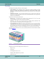
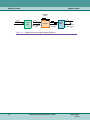
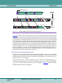
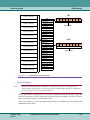
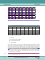
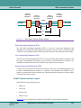
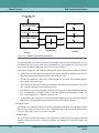
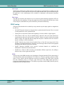
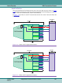
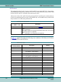
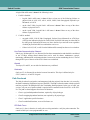
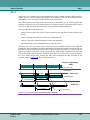
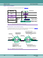
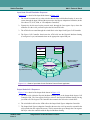
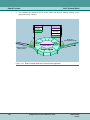
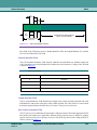
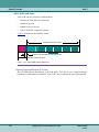
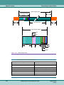
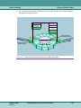
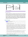
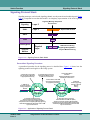
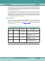
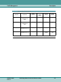
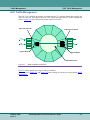
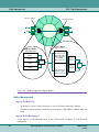
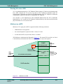
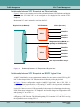
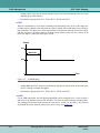
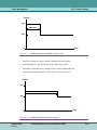
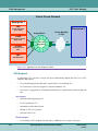
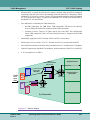
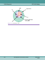
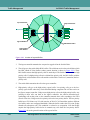
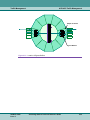
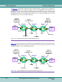
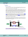
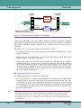
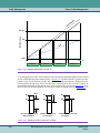
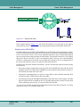
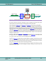
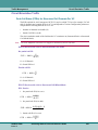
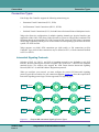
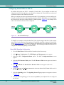
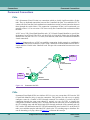
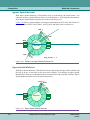
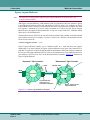
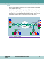
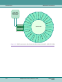
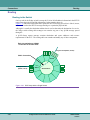
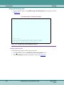
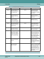
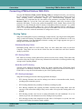
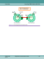
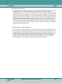
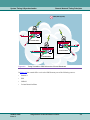
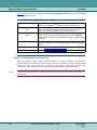
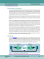
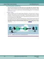
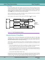
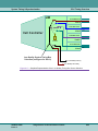
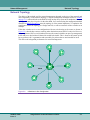
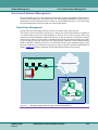
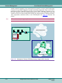
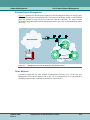
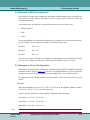
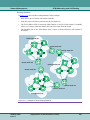
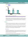
Traffic Management ACP/ACS Traffic Management Input Controller high low high low Ingress Buffers HOL HOL HOL HOL HOL HOL HOL HOL HOL HOL HOL HOL HOL HOL HOL HOL HOL HOL HOL HOL Output Controller high low high low ATM Switch Fabric Switch Fabric HOL Buffers Figure 2-22 Location of Ingress Buffers 3. The ingress controller transmits the accepted or tagged cell to the Switch Fabric. 4. The cell goes to the switch fabric HOL buffers. The cells then travel to the switch fabric which has HOL (Head Of Line) buffers (whose general location is shown in Figure 2-22). These HOL buffers ensure that high-priority cells are not delayed. The Switch Fabric can detect high priority cells. If a high priority cell arrives behind low-priority cells, the HOL buffer (with the high-priority cell) transmits all its cells and the switch fabric “clocks out” (transmits) the lowpriority ones. 5. The switch fabric transmits the cell to the egress controller. 6. High-priority cells go to the high-priority egress buffer. Low-priority cells go to the lowpriority egress buffer where they can be discarded during congestion.The cell now arrives at the Egress (output) controller. Xedge routes high-priority cells to the high-priority buffer. Any policing to these cells was done at the ingress controller, the software discarded nonconforming cells at that point, so the controller transmits these cells according to the FIFO (First In First Out). Xedge routes low-priority cells to the low-priority buffer. The low priority buffer has a CLP Point set at 512 cells (note the ACP/ACS Cell Controllers can have different size buffers and a user configured threshold). When the buffer reaches the CLP point, Xedge discards all subsequent cells. This condition is referred to as congestion. Note that Xedge empties the high-priority buffer before it transmits any cells from the low-priority buffer. Figure 2-23 shows the general location of the egress buffers. 2-34 ACS Xedge Switch Technical Reference Guide 032R310-V620 Issue 2 Traffic Management ACP/ACS Traffic Management high low high low HOL HOL HOL HOL HOL HOL HOL HOL HOL HOL HOL HOL HOL HOL HOL HOL HOL HOL HOL HOL Output Controller high low high low Egress Buffers Figure 2-23 Location of Egress Buffers 032R310-V620 Issue 2 ACS Xedge Switch Technical Reference Guide 2-35 Traffic Management Policing (Cell Controllers) Policing (Cell Controllers) Introduction Usage Parameter Control (UPC) is the set of actions performed by the network to monitor and control ATM cell traffic. The Xedge UPC applies the Generic Cell Rate Algorithm (GCRA) to ensure that cells conform to the Traffic Contract. This process is also referred to as Policing. The Traffic Contract is contained within the Connection Traffic Descriptor. The Traffic Contract specifies the traffic characteristics of a connection between ATM nodes. These characteristics include the Quality of Service, the Cell Delay Variation (CDV) Tolerance, and the Traffic Parameters. The Connection Traffic Descriptor specifies the traffic parameters at the public or private UNI. It is the set of traffic parameters in the Source Traffic Descriptor, the CDV Tolerance, and the Conformance Definition. The Connection Traffic Descriptor also contains the Source Traffic Descriptor. Connection Admission Control procedures use the Connection Traffic Descriptor to allocate resources and to derive parameter values for use with UPC. The Traffic Descriptor is a generic list of traffic parameters used to define the traffic characteristics of an ATM connection. Traffic Parameters include the Peak Cell Rate, Sustained Cell Rate, Maximum Burst Size (burst tolerance) and Cell Delay Variation Tolerance (CDVT). Note For SPVCs and SVCs, policing is a global link variable that is enabled/disabled for all connections on a link. For PVCs, policing is configured on a per connection basis. Peak Cell Rate (PCR) The Peak Cell Rate defines the upper boundary on the traffic submitted on an ATM connection and is expressed in terms of cells per second (cps). Sustained Cell Rate (SCR) The Sustained Cell Rate defines the upper boundary on the average cell rate of an ATM connection and is expressed in terms of cells per second (cps). Cell Delay Variation Tolerance (CDVT) Cell Delay Variation (CDV) describes the variation in elapsed time between the arrival of two cells on a connection (virtual path or virtual circuit). ATM cells for a particular connection can either be inserted or not inserted on a link every 53-bytes. Therefore, there are frequent delays in cell transfer for a particular connection due to the multiplexing of a number of ATM streams on one line. Cells of a particular VC or VP could be delayed going into a line causing cells to “bunch” at the line rate. Maximum Burst Size (MBS) The Maximum Burst Size (MBS) defines the Burst Tolerance for an ATM connection. In general, it is the number of cells that can be sent at the connection’s PCR without exceeding its SCR if the connection is idle for enough time between bursts. 2-36 ACS Xedge Switch Technical Reference Guide 032R310-V620 Issue 2 Traffic Management Policing (Cell Controllers) Supported Conformance Definitions The configuration of the policer on the ECC and ACP/ACS cell controllers is determined by the traffic parameters and the conformance definition of the circuit. Table 2-5 shows which traffic parameters are used to configure the policers per conformance definition. Table 2-6 shows the action taken by either the peak or sustained policers if cells are not conforming. CBR, CBR.A, CBR.B, VBR.A, VBR.B and VBR.C are proprietary conformance definitions used to support UNI 3.X conformance contracts (The ATM Forum User-Network Interface (UNI) Specification Version 3.1). The rest of the conformance definitions are from The ATM Forum Traffic Management Specification, Version 4.0 af-tm-0056.000, April 1996. Table 2-5 Xedge 5.1 Supported Conformance Definitions Traffic Parameters Conformance Definition PCR (clp0+1) PCR (clp0) SCR and MBS CLR CDVT Notes CBR Yes No Yes No clp=0 CBR.A Yes Yes Yes No clp=0 Force MBS(clp0) =1, SCR(clp0)=PCR(clp0) CBR.B Yes Yes Yes No clp=0 Force MBS(clp0) =1, SCR(clp0)=PCR(clp0) CBR.1 Yes No Yes No clp=0+1 VBR Yes No Yes No clp=0 Force MBS(clp0) =1, SCR(clp0)= PCR(clp0+1) VBR.A Yes Yes Yes No clp=0 Force MBS(clp0) =1, SCR(clp0)=PCR(clp0) VBR.B Yes Yes Yes No clp=0 Force MBS(clp0) =1, SCR(clp0)=PCR(clp0) VBR.C Yes No Yes (clp0+1) clp=0 VBR.1 Yes No Yes (clp0+1) clp=0+1 VBR.2 Yes No Yes (clp0) clp=0 VBR.3 Yes No Yes (clp0) clp=0 UBR.1 Yes No Yes No none UBR.2 Yes No Yes No none ABR ------ ------ -------- -------- Not supported in Xedge Table 2-5 032R310-V620 Issue 2 ACS Xedge Switch Technical Reference Guide 2-37 Traffic Management Table 2-6 Policing (Cell Controllers) Xedge 5.1 Non-Conformance Action Taken by Cell Policers Conformance Definition Non-Conformance Action Peak Bucket Sustained Bucket CBR discard n.c clp0+1 none CBR.A discard n.c clp0+1 discard n.c. clp0 CBR.B discard n.c clp0+1 tag n.c. clp0 CBR.1 discard n.c clp0+1 none VBR discard n.c clp0+1 discard n.c. clp0 VBR.A discard n.c clp0+1 discard n.c. clp0 VBR.B discard n.c clp0+1 tag n.c. clp0 VBR.C discard n.c clp0+1 discard n.c. clp0+1 VBR.1 discard n.c clp0+1 discard n.c. clp0+1 VBR.2 discard n.c clp0+1 discard n.c. clp0 VBR.3 discard n.c clp0+1 tag n.c. clp0 UBR.1 discard n.c clp0+1 none UBR.2 tag all cells ABR none Not Supported Table 2-6 2-38 ACS Xedge Switch Technical Reference Guide 032R310-V620 Issue 2 Traffic Management Policing (Cell Controllers) Generic Cell Rate Algorithm (GCRA) The Generic Cell Rate Algorithm (GCRA) is a virtual scheduling algorithm. It is also described as a “continuous state leaky bucket algorithm.” The GCRA continuously updates a Theoretical Arrival Time (TAT) of a connection’s ATM-cells. If a cell arrives faster than as specified by the connection’s traffic contract, the cell is non-conforming. The GCRA is divided into two main sections; one calculates the scheduling of PCR traffic and a second that calculates the scheduling of SCR traffic. Each of these two sections is commonly referred to as a bucket, thus the GCRA is often called the “dual leaky bucket algorithm.” As each ATM-cell arrives at a Xedge Cell Controller (with policing enabled) the GCRA determines if the cell conforms to the traffic contract of the connection. Enforcement To enforce Traffic Contracts, Xedge employs the GCRA to ensure ATM cells conform to their specified Traffic Contract. Xedge enforces the Traffic Contract at the ingress point of the network. To accomplish enforcement of the contract, Xedge can discard or tag ATM cells. Xedge implements enforcement in the hardware of each Xedge node. Traffic policing is done on a per VC or VP basis at each link. Bucket Principle The “leaky bucket” is defined by the GCRA. The purpose for the bucket on the PCR is to accommodate for CDV (Cell Delay Variation). The purpose for the bucket on the SCR is to accommodate for bursts of cells. The leaky buckets are not buffers through which cells pass. The buckets exist only in the mathematical calculations of the GCRA. Bucket Level The Bucket Leak Rate is constant. It is the configured rate for PCR or SCR (for the peak or sustained bucket respectively). Each time a cell arrives at a Cell Controller, the software calculates a new bucket level. If cells arrive at the exact configured rate, the bucket level will stay the same. If cells arrive earlier than the configured rate the bucket level will rise. If cells arrive later than the configured rate the bucket level will drop. 032R310-V620 Issue 2 ACS Xedge Switch Technical Reference Guide 2-39 Traffic Management Policing (Cell Controllers) Bucket Status Xedge Cell Controllers have a Virtual Circuit Status menu option. Selecting this option enables you to view the Virtual Circuit Status Table for each link. The Virtual Circuit Status Table displays the current status of the Peak (Pk -- also called bucket0 and Sustained (Sd -- also called bucket1) buckets used for policing. Figure 2-24 shows the Virtual Circuit Status Table. The following fields are used to report the bucket status: Xedge uses the bucket values, displayed on the Virtual Circuit Status screen (Figure 2-24) as shown in Table 2-7. Table 2-7 Bucket Status Definitions Relevant Hardware Status Field Peak Bucket for ACP/ ACS and ECC Cell Controllers Bucket 0 Value Bucket 0 Max Bucket 0 Increment Description Current Peak Bucket fill level (not supported on ECC) Maximum Peak Bucket Size (size of the bucket; displayed units are sample clock tics) increment added to peak bucket at arrival of each cell Peak Bucket Increment 1/[(configured Pk rate) x (sample clock period)] Sustained Bucket for ACP/ACS and ECC Cell Controllers Bucket 1 Value Current Sustained Bucket fill level (not supported on ECC) Bucket 1 Max Maximum Sustained Bucket Size (size of the bucket; displayed units are sample clock tics) Bucket 1 Increment increment added to the sustained bucket at the arrival of each cell Sustained Bucket Increment 1/[(configured Sd rate) x (sample clock period)] Table 2-7 Note 2-40 The GCRA adjusts the bucket only when a cell arrives at that bucket. ACS Xedge Switch Technical Reference Guide 032R310-V620 Issue 2 Traffic Management Policing (Cell Controllers) For Example Only - Do Not Copy Values Switch Name: Slot X SYS Virtual Circuit Status Table Detail of Virtual Circuit Status Table entry 0 SW Version Link : 0 Bkt 0 Max : 0 MaxBkt-ECC: VPI : 0 Bkt 0 Inc : 0 CurBkt-ECC: VCI : 5 Bkt 1 Cur : 0 MinQSz-ECC: TXd Cells : 8004 Bkt 1 Max : 0 CurQSz-ECC: TXd Clp1 C: 0 Bkt 1 Inc : 0 Eg Dsc Cel: 0 VC Type : mgmt vc Eg CLP1 Ds: 0 DSlot : 1 RXd Cells : 8017 DLink : 7 RXd CLP1 C: 0 DVPI : 0 Sd Excess : 0 DVCI : 128 Pk Excess : 0 Fd Int Vpi: 0 Cell Hd Va: 0x80 Fd Int Vci: 128 Cell Hd Ma: 0xf0000000 Bd Int Vpi: 0 Cell Swt H: 0x2f148 Bd Int Vci: 5 Bkt Contro: 0xc0000 PkShpg-ECC: 0 Bkt 0 Cur : 0 SdShpg-ECC: 0 Select option: Down, Enter entry number to edit, Goto row, Index search, Summary, eXit 0 0 0 0 Figure 2-24 Extra Detail Screen of Virtual Circuit Status Table 032R310-V620 Issue 2 ACS Xedge Switch Technical Reference Guide 2-41 Traffic Management Policing Configuration Policing Configuration When you configure a connection, you define the PCR and CDVT for CBR. For VBR-High, VBRmedium and VBR-low connections, you define the SCR, PCR, CDVT and MBS (Maximum Burst Size). If cells arrive at a rate greater than the PCR specified (after the bucket is full), or for longer than the CDVT, they are non-conforming. If cells arrive at a rate, greater than the SCR, for longer than the MBS, they are non-conforming. The policing function enables you to manage these nonconforming cells. Bucket Variables Table 2-8 lists some of the important abbreviations used when configuring policing: Table 2-8 Policing Abbreviations Abbreviation Definition Sd Sustained Pk Peak BI Bucket Increment. Also represented as T (Pk), or Ts (Sd), or TL (Line) BS Bucket Size (in ATM Traffic Contract) Bmax Maximum Bucket Level within the Xedge Switch Software (Units= sample clock tics) Bvalue Current bucket fill level (Units= sample clock tics) MBS Maximum Burst Size Table 2-8 Bucket Increment (BI) 1 BI sust = -------------------------------------------------------------------------------------------------------------------ConfiguredPeakRate × SampleClockPeriod 1 BI peak = --------------------------------------------------------------------------------------------------------------------------------ConfiguredSustainedRate × SampleClockPeriod The ACP/ACS uses 10ns clock periods. This results in SampleClockPeriod being 1/100,000,000. The ECC uses 40ns clock periods, which results in SampleClockPeriod being 25,000,000. Xedge always truncates the BI value, which leads to the policer allowing slightly more traffic in than is configured. The following example is for an ACP/ACS controller: 1 BI = --------------------------------------------- = 7937.77 12, 598cps × 10ns Xedge truncates the 7937.77 to 7937 and uses this truncated value (7937) for the Bucket Increment (BI). The actual policing rate is 12599cps (100,000,000/7936). As the requested cell rate increases, the error will greater, as evidenced below when the requested rate is 284,000 cps: 1 BI = ------------------------------------------------ = 352.11 284, 000cps × 10ns Actual policing rate = 100,000,000/352 = 284,090 cps 2-42 ACS Xedge Switch Technical Reference Guide 032R310-V620 Issue 2 Traffic Management Policing Configuration Minimum Supported Policing Rate As the shaping rate decreases, the size of the bucket increment increases. The minimum supported policing rate therefore is determined by the number of bits used to represent the policing increment. On the ACP/ACS, there are 32 bits available for the policing rate and therefore the minimum policing rate is 1. There are 20 bits available for the policing rate on the ECC, which yields a minimum policing rate of approximately 24 cps (0xfffff = 1,048575 => 25,000,000/1,048,575 = 23.8cps) Bucket Max The bucket max levels are calculated by Xedge using the following method: 1 CDVT Bmax peak = ----------------------------------------------------- × --------------------------SampleClockPeriod 1, 000, 000 Bmax sustained = ( MBS – 1 ) × ( BI sustained – BI peak ) + Bmax peak Policing Expressions Table 2-9 lists some expressions used with policing and their definitions. Table 2-9 Policing Expressions Expression Definition Peak Excess Number of cells discarded because of Peak Bucket policing action on ACP/ACS Cell Controllers Sustained Excess Number of cells discarded because of Sustained Bucket policing action on ACP/ACS Cell Controllers Table 2-9 PCR and SCR Bucket Size Bucket size, in Xedge, is the Burst Tolerance as specified by the ATM Forum UNI 3.1. The Xedge Switch Software calculates the bucket size (burst tolerance) for SPVCs after you enter a value for the MBS (Maximum Burst Size). For PVCs, you need to calculate the bucket size and enter that value during configuration. PVC Ingress and Egress In this example, we will describe ingress and egress as it relates to PVC connections. Please keep in mind that we need to enter all the Fd and Bd rates for Connection Admission Control (CAC) purposes (if applicable). Let’s say we want a connection between two user endpoints. We want to police the cells coming into our “network” from both user endpoints. Since the Xedge software considers Ingress and Egress in terms of source and destination we only need to be careful to configure our modes (Fd, Bd) to be consistent with how we defined our source and destination. Note that Fd (forward) is from the source to the destination and Bd (backward) is from the destination to the source. 032R310-V620 Issue 2 ACS Xedge Switch Technical Reference Guide 2-43 Traffic Management Policing Configuration In Figure 2-25 we decided to consider the end-to-end connection as going from User Endpoint X (X) to User Endpoint Y. We needed to configure 3-PVCs to accomplish this. We considered every Slot/Link on the “X” side to be the “source,” and every Slot/Link on the “Y” side to be the “destination.” In this case, we want to set the Mode in PVC #1 to “on” (for example, clp01 disc) in the Fd direction and “off” in the Bd direction. For PVC #3 we want the Fd Mode set to “off” and the Bd Mode set to “on” (for example, clp01 disc). PVC #1 PVC #3 PVC #2 Fd Mode “On” (IE, clp01 disc) Bd Mode Off Fd Mode Off Bd Mode “On” (IE, clp01 disc) Fd, Bd Modes Off Node A Node B Node C User Endpoint User Endpoint X Y Source Source Source Destination Destination Destination Figure 2-25 Example of End-to-End Connection Using PVCs Figure 2-26 shows the typical way to define the source and destination. In this case the links closest to the user Endpoints (in nodes A and C) are defined as the sources of their respective PVCs. In this example the Mode is “set” in the Fd direction only. PVC #1 Fd Mode “On” (IE, clp01 disc) Bd Mode Off PVC #3 PVC #2 Fd Mode “On” (IE, clp01 disc) Bd Mode Off Fd, Bd Modes Off Node A Node B Node C User Endpoint User Endpoint X Y Source Destination Source Source Destination Destination Figure 2-26 Typical Example of End-to-End Connection Using PVCs 2-44 ACS Xedge Switch Technical Reference Guide 032R310-V620 Issue 2 Traffic Management Policing Configuration PVC Configuration Considerations For Example Only - Do Not Copy Values Switch Name: Slot x SYS PVC Configuration/Status Table Detail of PVC Configuration/Status Table entry 0 SW Version Dest Slot : 2 08 Sd Fd Mode: off 18 CLP1 Disc : off VBR1 C Dest Link : 0 09 Sd Bd Rate: 0 Dest VCI : 1 10 Bd MBS(Cel: 0 Dest VPI : 1 11 Sd Bd Mode: off Src Slot : 4 12 Service Ca: cbr Src Link : 0 13 Multicast : no Src VCI : 1 14 Direction : bidirect Src VPI : 1 15 Frame Disc: disallow 00 Pk Fd Rate: 75 16 Enable UBR: off 01 Fd CDVT(uS: 20000 17 Status : running 02 Pk Fd Mode: off Error Code: ok 03 Pk Bd Rate: 75 Num Leaves: 04 Bd CDVT(uS: 20000 Fwd Int VP: 1 05 Pk Bd Mode: off Fwd Int VC: 1 06 Sd Fd Rate: 0 Bwd Int VP: 1 07 Fd MBS(Cel: 0 Bwd Int VC: 1 Select option: Add entry, Down, Enter entry number to edit, Goto row, Kill entry, Move entry, Press ^J for extra help on this item, Summary, eXit Figure 2-27 PVC Configuration/Status Table Detail ECC Buffer Management Configuration The CLP1 Disc parameter in the PVC Configuration/Status Table detail screen (shown in Figure 2-27) is used for ECC egress buffer management on CBR or VBR connections only. You should set the CLP1 Disc parameter to: • on for VBR.2, VBR.3 and CBR • off for CBR.1 and VBR.1 You set the conformance definition when you configure the Pk Bd Mode and Sd Fd Mode parameters in the PVC Configuration/Status Table (shown in Figure 2-27). The ATM Forum Traffic Management 4.0 specification defines the UBR.1 and UBR.2 conformance definitions. Tagging is not applicable for UBR.1. The specification allows tagging for UBR.2 cells. The Enable UBR parameter (in the PVC Configuration/Status Table) allows you to configure tagging for UBR cells according to the UBR.2 definition. 032R310-V620 Issue 2 ACS Xedge Switch Technical Reference Guide 2-45 Traffic Management Policing Configuration Table 2-10 shows how the Bucket Modes relate to the ATM Forum Traffic Management 4.0 conformance definitions. Table 2-10 TM 4.0 Conformance Definitions Mapped to Xedge Bucket Mode Conformance Definition Pk Bucket Mode Sd Bucket Mode cbr.1 clp01 discard n/a vbr.1 clp01 discard clp01 discard vbr.2 clp01 discard clp0 discard vbr.3 clp01 discard clp0 tag ubr.1 clp01 discard n/a ubr.2 clp01 discard (must Enable UBR Tagging -the n/a Enable UBR parameter) Table 2-10 SPVC Bucket Configuration The Xedge software calculates the bucket values for SPVC connections. In order for the software to calculate the bucket levels you must enter a value for the Maximum Burst Size (Max Fd Burst Sz and Max Bd Burst Sz) in the SPVC Configuration/Status Screen (shown in Figure 2-28). For Example Only - Do Not Copy Values Node B: Slot 3 SPVC Configuration/Status Table New Event Detail of SPVC Configuration/Status Table entry 0 ID : 1 14 Source VPI : 0 Call ID : 15 Target VCI : 0 00 Source Link : 0 16 Target VPI : 0 01 Dest Address : 17 Timeout : 5 02 Pk Fd Rate(CPS): 0 Connect Time : 0 03 Peak Frd Mode : clp01 discard 18 Num of Retries : 0 04 Pk Bd Rate(CPS): 0 Failures : 0 05 Peak Bwd Mode : clp01 discard 19 Alert Cfg : no trap 06 Sd Fd Rate(CPS): 0 Cause and Diag : none 07 Max Fd Burst Sz: 0 Type : active 08 Sus Frd Mode : clp0 discard 20 Call State : idle 09 Sd Bd Rate(CPS): 0 Status : idle 10 Max Bd Burst Sz: 0 CauseDiag Code : 0 11 Sus Bwd Mode : clp0 discard 21 Connection Type: pt pt 12 QOS Class : cbr 13 Source VCI : 0 Working... Down, Enter entry number to edit, Goto row, Press ^J for extra help on this item, disPlay route, Summary, eXit Figure 2-28 SPVC Configuration/Status Screen 2-46 ACS Xedge Switch Technical Reference Guide 032R310-V620 Issue 2 Traffic Management Policing Configuration CDVT CDVT is expressed in µ-seconds (the number of clumped cells at the PCR). Figure 2-29 illustrates CDVT. You can find a detailed explanation of Cell Delay Variation (CDV) as it applies to the CE/SCE application in Cell Delay Variation Tolerance (CDVT) on page 2-36. Line Rate 353,207 c/s Expected PCR 176,000 c/s Actual PCR 5.6µs 8.49µs CDVT Size = 1.5 Figure 2-29 CDVT Diagram Converting CDVT (µsec) to Cell Count If desired you can use the following formula to convert CDVT expressed as time to a cell count: n = 1 + 〈 CDVT ⋅ lineerate〉 where: CDVT is in µ sec n= the number of clumped cells Mode The Conformance Definition specifies flow and tagging options. It is defined for each connection during configuration and used by the GCRA. The CLP (Cell Loss Priority) is configured for the PCR and SCR separately. Table 2-11 and Table 2-12 list the flow and tagging options and definitions for the PCR and SCR respectively. The policing mode enables you to select how Xedge should police non-conforming ATM cells. You can configure each controller for the following policing modes: 032R310-V620 Issue 2 ACS Xedge Switch Technical Reference Guide 2-47 Traffic Management Policing Configuration Table 2-11 PCR Flow and Tagging Options Option off Definition Policing is off. Xedge does not police any cells. clp 0 disc Xedge polices the cells that have their clp-bit set to zero. Cells with the clp-bit set to 1 are ignored by the GCRA. If a non-conforming cell arrives with its clpbit equal to zero, Xedge will discard that cell. clp 1 disc Xedge polices the cells that have their clp-bit set to one. Cells with the clp-bit set to zero are ignored by the GCRA. If a non-conforming cell arrives with its clp-bit equal to 1, Xedge will discard that cell. clp 0 1 disc Xedge polices all arriving cells. Xedge will discard any non-conforming cell. This is the most common mode selection. Table 2-11 Table 2-12 SCR Flow and Tagging Options Option Definition clp 0 disc Only cells set to clp 0 are subject to policing. Non-conforming cells are discarded. clp 1 disc Xedge polices the cells that have their clp-bit set to one. Cells with the clp-bit set to zero are ignored by the GCRA. If a non-conforming cell arrives with its clp-bit equal to 1, Xedge will discard that cell. clp 0 1 disc clp 0 tag Xedge polices all arriving cells. Xedge will discard any non-conforming cell. This is the most common mode selection. Xedge polices cells with their clp-bit set to zero. If these clp0 cells are nonconforming, Xedge will change their clp-bit to one and then let them continue. Table 2-12 2-48 ACS Xedge Switch Technical Reference Guide 032R310-V620 Issue 2 Traffic Management Frame Traffic Frame Traffic Congestion Controller Congestion Congestion occurs when a large burst of high level applications, such as excessive server access requests, (especially when two items are separated by FRC/CHFRC Adaptation Controller) results in stalled file transfers and processors not being available. Congestion is measured internally by the FRC/CHFRC Adaptation Controller in terms of the number of system buffers available. The FRC/CHFRC has a pool of approximately 3600 system buffers. Each buffer is 1028 bytes in length. On start-up, the FRC/CHFRC distributes up to 1024 buffers to the segmentation engine so that it can create a queue of receive buffers for reassembly of cells into frames. The FRC Adaptation Controller also gives 500 buffers to each link on the frame side for creation of a queue to receive frames. The CHFRC Adaptation Controller also gives up to 128 buffers to each channel on the frame side for creation of a queue to receive frames. When the FRC/CHFRC Adaptation Controller receives a frame from the frame network (Figure 2-30), it processes the FR header and queues it for segmentation into the ATM network. When the FRC/CHFRC reassembles a frame from the ATM network (Figure 2-31), it processes the FR header and queues it for transmission into the frame network. After a frame has been received or reassembled, the FRC/CHFRC replenishes the receive queue with another buffer allowing the FRC/ CHFRC to continue receiving and reassembling. As frames queue up for segmentation into the ATM network or for transmission into the frame network, the buffer pool becomes depleted and this results in congestion. Frames queue up for segmentation or transmission because the rate at which frames are being received is greater than the rate at which they are being transmitted. Receive Queue Transmit Queue Frame received Frame Queue for Processing segmentation Frames Cells Receive Queue Buffer Pool Segmentation complete replenished Congestion occurs when the Transmit Queue becomes too large. Figure 2-30 Flow of Buffers in the Frame-to-ATM Direction 032R310-V620 Issue 2 ACS Xedge Switch Technical Reference Guide 2-49 Traffic Management Frame Traffic Transmit Queue Reassembly Queue Queue for transmission Frame Processing Frame received Frames Cells Transmit complete Buffer Pool Congestion occurs when the Transmit Queue becomes too large. Reassembly Queue replenished Figure 2-31 Flow of Buffers in the ATM-to-Frame Direction Frame relay connections report FRC/CHFRC Adaptation Controller congestion via BECN (Backward Error Congestion Notification) and FECN (Forward Error Congestion Notification). FRC/CHFRC Adaptation Controller congestion is not reported on Frame Transport and FUNI connections. The various levels of system buffer congestion are reported as follows: • Low Buffer Congestion: 50% of the buffer pool is depleted. FECN and BECN are set in all frame relay frames. • High Congestion: 75% of the buffer pool is depleted. FECN, BECN and the DE (Discard Eligible) bits are set in all frame relay frames. • Critical Congestion: 90% of the buffer pool is depleted (10% of the buffer pool is reserved for ILMI and OAM usage). Once the critical congestion is reached, the frame side and ATM side can no longer replenish their pools of input system buffers (used to receive frames). In this condition, frames are dropped before they can enter the FRC/CHFRC Adaptation Controller. As in high congestion, all frames that do pass through the system during critical congestion have FECN, BECN and DE bits set. ATM Segmentation Engine Congestion The segmentation engine has two congestion mechanisms: 1. For all VCs: the driver is considered congested (BECN is set in frames in the ATM-to-frame direction, FECN is set in frames in the frame-to-ATM direction) when more than 30% of the system buffers are queued at the segmentation engine. If the total number of buffers queued exceeds 40% of the buffer pool, then any additional frames to be transmitted will be dropped. The segmentation engine driver remains in the congested state until there are less than 25% of the system buffers queued. Note 2-50 Under normal circumstances, the transmit functions in the segmentation engine driver will not immediately free buffers after they have already been transmitted. For performance reasons, the transmit functions only free buffers after 10 frames have been transmitted. When buffer congestion is encountered, the transmit functions will attempt to free transmitted buffers before each transmit. ACS Xedge Switch Technical Reference Guide 032R310-V620 Issue 2 Traffic Management Frame Traffic 2. On a PVC and SPVC basis, the segmentation engine driver allows each VC to queue up a maximum of 10% of the system buffers on the transmit queue (this transmit queue is on the FRC/CHFRC Adaptation Controller and should not be confused with the on Cell-Based Controllers). If the VC queues 7.5% of the system buffers, then the PVC/SPVC is considered to be congested (BECN is set in frames in the ATM-to-frame direction, FECN is set in frames in the frame-to-ATM direction). Frames will be dropped if the VC queues more than 10%. The VC will remain in the congested state until the number of buffers queued goes below 5%. Frame Side Congestion On the FRC Adaptation Controller, each link’s transmit queue can contain up to 20% of the system buffers before frames are discarded. A link will be considered congested (BECN is set in frames in the frame-to-ATM direction, FECN is set in frames in the ATM-to-frame direction and DE=1 frames are discarded) when 15% of the system buffers are queued, the link will remain in the congested state until there are less than 10% of the system buffers queued. The CHFRC Adaptation Controller allows each channel to queue up for transmit one second of the theoretical bandwidth of the channel before frames are discarded. When the queue becomes threequarters full, the channel is considered congested and will discard DE=1 frames. It remains congested until the number of bytes queued goes below the half second mark. Frames will be dropped when the number of bytes queued exceeds the one second mark. Network Congestion The FRC/CHFRC Adaptation Controller forwards FECN and BECN as specified in FRF5 and FRF8. Likewise, the ATM EFCI bit is also handled as specified. The FRC/CHFRC is a network device even though it utilizes user LMI. As a network device, it does not respond to frame relay network congestion (for example, it does not throttle down frame transmit while receiving frames with BECN set). This is the function of the CPE device. Discard Eligibility and CLP Mapping Frame connections and ATM connections use different methods to tag and discard frames and cells respectively. Frames use the DE bit (Discard Eligible bit described in Frame Relay Frames on page 1-57) while ATM cells use the CLP bit (Cell Loss Priority bit described in ATM Header Fields on page 1-35). Xedge maps DE to CLP as follows: • In the Frame Relay to ATM direction the DE field is used to set the CLP field of each resulting ATM cell. • In the ATM to Frame Relay direction, the CLP field, in the last cell resulting from a frame relay frame, is used to set the DE field in the reassembled frame relay frame. 032R310-V620 Issue 2 ACS Xedge Switch Technical Reference Guide 2-51 Traffic Management Frame Traffic Management Frame Traffic Management There are three traffic management schemes on the FRC/CHFRC Adaptation Controller: • Connection Admission Control • Traffic Policing • Traffic Shaping Connection Admission Control Connection Admission Control (CAC) functions on the FRC/CHFRC by checking for available bandwidth for each link. CAC considers each link as a separate connection and only accepts new VCs (virtual circuits) on the link if the required bandwidth is available. When you configure a frame relay or Frame Transport circuit you enter a value for the CIR (Committed Information Rate). CAC uses this value to calculate the EIR (Excess Information Rate) using the following formula: IngressCIR EIR = IngressBe ------------------------------ IngressBc where Bc = committed burst size and Be = excess burst size CAC adds the EIR and CIR together for any attempted VC (Virtual Connection). This total must be less than or equal to the bandwidth available or CAC will cause the VC to remain notInService. The status screen displays the bandwidth on the link so that you can enter an acceptable CIR value. Quality of Service QoS, as defined for Xedge Cell Controllers, is not supported for the FRC/CHFRC. The QoS setting for these controllers is used to: • indicate whether CAC should subtract bandwidth when completing the Frame Relay / Frame Transport VC • whether or not frames should be marked as discard eligible. The behavior of QoS is as follows: • VBR-High - not supported • VBR Medium - CIR is subtracted from the high priority bandwidth available on the link or channel. • VBR Low - nothing is subtracted from the high priority available bandwidth. All ingress frames are marked as discard eligible. Traffic Policing In order to throttle the amount of traffic that a user can send to the ATM network, the FRC/CHFRC polices frame relay and frame transport traffic in the frame-to-ATM ingress direction. If frames arrive too quickly, the FRC/CHFRC will either mark them Discard Eligible (DE) or discard them. The FRC/CHFRC does not police FUNI traffic in either direction nor does it police FR and FT in the ATM-to-frame egress direction. The FRC/CHFRC Adaptation Controller policing is governed by three user specifiable parameters that are specified for each virtual circuit (VC) configured on the controller: 2-52 ACS Xedge Switch Technical Reference Guide 032R310-V620 Issue 2 Traffic Management Frame Traffic Management 1. Committed Information Rate (CIR) 2. Committed burst size (Bc) 3. Excess burst size (Be) A fourth parameter, Tc, is calculated by the FRC/CHFRC Adaptation Controller. Tc specifies the time interval during which the number of bytes transmitted by the user is accumulated and compared against Bc or Bc + Be. Bc is the maximum amount of data that the FRC/CHFRC agrees to transfer, under non-congested conditions during Tc. Be is the amount of uncommitted data, in excess of Bc, that the FRC/CHFRC attempts to transmit during Tc. Tc (in milliseconds) is calculated according to ITU Recommendation I.370 as shown in Table 2-13. Table 2-13 Tc Calculation CIR Bc Be Tc >0 >0 >0 Tc = Bc/CIR >0 >0 =0 Tc = Bc/CIR =0 =0 >0 Tc = Be/access rate Table 2-13 FR frames that fit into the committed bucket are passed through the policing system untouched. FR frames that exceed Bc but are below Be will be tagged as discard eligible, provided the “Tag Options” parameter is set “yes” and Be is non zero. FR frames that exceed both the committed and excess burst rates are discarded. FT traffic can be discarded but not tagged. FT frames under Bc are forwarded to the ATM network unmodified. Otherwise the frames are discarded. Policing does not delay or queue data. It is used in the calculation of the instantaneous amount of traffic that is arriving from one frame relay or frame transport VC. Figure 2-32 illustrates how Bc and Be interact with Tc. Frames 1 through 4 are transmitted to the FRC/CHFRC at the access rate, Link B/W. Frames 1 and 2 are less than Bc. Frame 3 is greater than Bc and less than Be and, therefore, is tagged Discard Eligible (DE). Frame 4 is greater than Be so it’s discarded. Note that if the frames arrived back-to-back, frame 4 would be discarded along with any subsequent frames received within Tc. 032R310-V620 Issue 2 ACS Xedge Switch Technical Reference Guide 2-53 Traffic Management Frame Traffic Management ss ce c A te Ra Bits Received Be + Bc Bc CIR Time T0 + Tc T0 Frame 1 Frame 3 Frame 2 Frame 4 Figure 2-32 Relationship Between Bc, Be, Tc To avoid tagging more DE=0 frames than necessary, the policing algorithm handles frames marked as DE=0 differently than those marked as DE=1. Figure 2-33 (a) shows that DE=0 frames cause the bucket level to rise towards Bc plus Be. DE=1 frames are subtracted from the Bc plus Be level, lowering the Bc plus Be level. If there are more DE=1 frames than Be, the extra DE=1 frames are not discarded or tagged; the Bc plus Be level is lowered below Bc as shown in Figure 2-33 (b). If there are more DE=0 frames than Bc, the extra DE=0 frames are tagged as shown in Figure 2-33 (c). Be DE=1 Bc Be DE=1 Bc DE=0 (a) policing treatment of DE=0 and DE=1 (b) DE=1 below Bc are not discarded Be Bc DE=0 (c) DE=0 frames above Bc are tagged Figure 2-33 Handling of DE=0 versus DE=1 frames 2-54 ACS Xedge Switch Technical Reference Guide 032R310-V620 Issue 2 Traffic Management Frame Traffic Management The calculated Tc is rounded to the nearest 50 ms interval by the FRC or CHFRC. This can cause the FRC or CHFRC to over police or under police the incoming frames. For example, if the calculated Tc is 524 ms, the FRC/CHFRC will round the Tc value to 500 ms. In this case, there will be less time for Bc so the FRC/CHFRC will under-police the incoming frames. If the calculated Tc is 526 ms, the FRC/CHFRC will round the Tc value to 550 ms. In this case, there will be more time for Bc so the FRC/CHFRC will over-police the incoming frames. To prevent these two scenarios, you should set Bc and CIR so that Bc divided by CIR yields a result that is a multiple of 50 (ms). The FRC/CHFRC has several caveats concerning the setting of the CIR, Bc, and Be. First, circuits configured with CIR, Bc, Be equal to zero will result in policing being disabled. Second, if the CIR equals the access rate, then policing is disabled for the circuit. Third, if a FRC/CHFRC traffic contract is configured such that Bc and CIR are both zero, and Be is greater than 0, policing WILL be enabled. However, frame discarding will be minimal, and will decrease as Be decreases from line rate. This is due to the fact that the computer Tc value will be small, and therefore the rate of traffic allowed to pass through undiscarded will be high. Bits Received In Figure 2-34, each Tc window operates independently and asynchronously. Tc is a sliding window that is opened when ingress data is received. The Tc window is shut when its computed duration expires. Once Tc expires, the Bc/Bc and Be counts are zeroed. A new Tc will start when additional data is received. Time Tc1 Tc2 Tc3 Tc4 Tc5 Figure 2-34 Each Tc Operating Independently and Asynchronously Traffic Shaping ATM traffic shaping is a mechanism that the FRC/CHFRC Adaptation Controller uses to conform the ATM cells generated from frame relay, frame transport and FUNI frames to a rate specified in an ATM traffic contract (Peak Cell Rate - PCR, Sustained Cell Rate - SCR, and Maximum Burst Size - MBS). Traffic shaping should not be confused with traffic policing. Policing is concerned with how fast and how much frame traffic is arriving at the FRC/CHFRC Adaptation Controller. Shaping is concerned with how fast the cells of a segmented frame enter the ATM network. Policing will mark or discard certain frames from a burst. Shaping will cause a burst of frames to queue up in the FRC/CHFRC as their cells enter the ATM network at either the PCR or SCR. Traffic Shaping Example When frames enter the FRC/CHFRC Adaptation Controller they are segmented into ATM cells. Each ATM cell contains a 48-byte payload (plus a 5-byte header) to carry the frame. The number of ATM cells required to carry the frame depends on the size of the frame. The following is a hypothetical example to demonstrate how Traffic Shaping works. 032R310-V620 Issue 2 ACS Xedge Switch Technical Reference Guide 2-55 Traffic Management Frame Traffic Management Let’s assume that we have frame traffic with frames that contain 3984-bytes of data each. Since each ATM cell can contain 48-bytes of payload, the FRC/CHFRC will segment each frame into 83ATM cells as shown in Figure 2-35. 83-ATM Cell Burst ATM Cell ATM Cell ATM Cell ATM Cell ATM Cell ATM Cell ATM Cell ATM Cell ATM Cell ATM Cell ATM Cell ATM Cell ATM Cell ATM Cell ATM Cell ATM Cell 2.83µ s Figure 2-35 3984-Byte Segmented Frame The circuit is connected to an OC3 line that supports 353,257 cells per second (cps) as the backward cell rate, thus each frame would travel through the ATM network in bursts of 83-cells, with a 2.83µ s delay between cells (1/cell rate). If the frames arrive at the rate of 96 per second, this would translate to about 8000 cps (7968 cps = 96 bursts of 83 cells). Each burst would be 10ms apart (1/bursts per second). Figure 2-36 illustrates unshaped ATM traffic leaving the ATM node. OC3 3984 byte frame 3984 byte frame CHFRC ACS 10ms = 83 ATM Cells Figure 2-36 Unshaped ATM Traffic The problem with the bursty traffic is that it could begin to fill a Slot Controller’s buffers and cells could be lost due to buffer congestion. Shaping corrects this situation by spacing the ATM cells so they leave the Xedge FRC/CHFRC Adaptation Controller at a steady rate. This shaping is done automatically by Xedge and the shaping rate is reported so that you can plan other connections with the remaining bandwidth. 2-56 ACS Xedge Switch Technical Reference Guide 032R310-V620 Issue 2 Traffic Management Frame Traffic Management OC3 3984 byte frame 3984 byte frame CHFRC ACS 125µ s ATM Cell ATM Cell 125µ s Figure 2-37 Shaped ATM Traffic In the example shown in Figure 2-37, each ATM cell would be 125µ s apart and we can expect a steady 8000 cps for this connection. The preceding diagram illustrates the shaped ATM traffic. Shaping on the FRC/CHFRC For FUNI connections, the PCR, SCR and MBS are specified during circuit configuration. Specify a PCR for FUNI connections that takes into account the size of the frames being transmitted. Failure to do so can result in a frame versus cell rate mismatch and frames may be unexpectedly dropped due to too many frames being queued at the SAR Engine. The problem is that AAL5 will segment frames into 48 byte cells and if a cell is not completely filled, a 48 byte cell is still transmitted. Therefore, a frame between 49 and 96 bytes in length will consume 2 cells. Even though most of the second cell will not be used, its use must be factored into the PCR. For frame relay and frame transport connections, you have the following options when specifying PCR and SCR: • having the software automatically derive the PCR, SCR and MBS from the CIR, Bc and Be (formulas specified in ATM Forum’s BISDN Inter Carrier Interface Specification Version 2.0, ATM Forum document af-bici-0013.003). • allowing the segmented frames to enter the switch fabric at the maximum allowable PCR (20,000 cps for the CHFRC and 225,000 on the FRC). • specifying the PCR, SCR and MBS independently of the frame relay traffic contract. Note that the user specified PCR is rounded up one of 36 possible shaping rates provided. The specified SCR is rounded up to the nearest 12.5 percent of the PCR selected. You specify how the PCR and SCR will be determined on the Frame Relay/Transport VC Config menu screen via the T.P. translation menu item. 032R310-V620 Issue 2 ACS Xedge Switch Technical Reference Guide 2-57 Traffic Management Frame Traffic Management If you select to have the software automatically generate the ATM traffic contract then there are two options, method 21 and method 22. The following discussion details the calculations behind methods 21 and 22. • method 21 ( bandwidth × OHA ) PCR = ---------------------------------------------------8 where: ( InfooFielddLength + 10 ) × 0.0208 OHA = ------------------------------------------------------------------------------------------------( InfooFielddLength + 6 ) Note: x = smallest integer value greater than or equal to x • method 22 Be CIR + CIR × ------ × OHB Bc PCR = ---------------------------------------------------------------------8 where: [ ( InfooFielddLength + 10 ) × 0.0208 ] OHB = ----------------------------------------------------------------------------------------------InfooFielddLength Note: x = smallest integer value greater than or equal to x CIR × OHB SCR = ----------------------------8 1 Bc MBS = ------ × ------------------- + 1 × OHB 8 CIR 1 – ---------- AR The calculated PCR, SCR, MBS for FR/FT and the user specified PCR, SCR, and MBS for FUNI are changed due to the limitations in the ATM segmentation engine on the FRC/CHFRC. The segmentation engine employs 12 different cell rates, shown in Table 2-14 and Table 2-15. Each cell rate has 3 subrates: 100%, 50%, and 25% for a total of 36 different cell rates. All 36 values can be used as a PCR. The software rounds a user’s calculated PCR up to the nearest value. The cell rates vary depending upon the DOC card installed in the FRC/CHFRC, as shown in the following: The SCR is rounded up to the nearest 12.5 percent of the PCR selected. Assume 0 < (SCR / PCR) < 1, then choose the lowest integer K such that: ( K × 0.125 ) > ( SCR ⁄ PCR ) . Then: actuallSCR = ( K × 0.125 ) × actuallPCR If you specify a FUNI traffic contract of PCR = 4000 and an SCR = 3000 (for a CHFRC), the actual PCR would be 4167 (rate number = 4.25% cell rate) and the actual SCR would be: 3125 × ( 4167 × 0.75 ) . 2-58 ACS Xedge Switch Technical Reference Guide 032R310-V620 Issue 2 Traffic Management Frame Traffic Management The MBS is also changed due to the SAR Engine. Determining the actual MBS can be a two step process depending on whether or not the MBS will overflow the PCR bucket of the SAR Engine: determining the size of the SAR’s leaky bucket (M) and then determining the actual MBS from M. The two formulas are shown as follows: (1) SCR M = ( MBS – 1 ) ⋅ 1 – ------------ PCR where: MBS - the MBS calculated for FR/FT or specified for FUNI M = leaky bucket capacity use in the SAR for shaping SCR = SCR rounded up to the 12.5% of the actual PCR PCR = calculated PCR rounded up to the nearest of the 36 cell rates (2) M ActualMBS = ----------------------------------------SCR 1 – ------------ + 1 PCR M is limited to a range of 1-255. If M is less than 255, then the actual MBS is the specified (FUNI service type) / calculated (frame relay/transport service type) MBS. If M is greater than 255, then the actual MBS must be derived from equation 2. Every VC will be assigned with a shaping rate which is the smallest available rate greater than the PCR or calculated PCR. If PCR = SCR = MBS = 0, or CIR = Bc = Be = 0, the highest shaping rate will be used, 225,000-cps for the FRC or 20,000-cps for the CHFRC. Shaping Anomaly on the CHFRC and FRC There is a anomaly in the segmentation engine for the FRC and CHFRC that causes the FRC and CHFRC to incorrectly shape cells. The anomaly causes the FRC and CHFRC to occasionally release an additional cell from the PCR and SCR leaky buckets. This violates not only the cell delay variation but also increases the effective PCR and SCR of the configured ATM traffic contract associated with the ATM virtual circuit. The ATM traffic contract for a frame VC is displayed when the frame to ATM virtual circuit is configured (refer to PCR, SCR and MBS in the Frame Relay/Frame Transport/PPP VC Config Menu) Note For example, if a virtual circuit were configured on the FRC for a PCR of 30,000 and a burst of frames arrived for segmentation, then the FRC would send out a cell every 33µ s. If one of those 33µ s cell intervals was in error then one of the cells would be released within 5µ s after the start of the cell interval and then another cell would be released after another 28µ s, at the normally scheduled time. This pattern is shown in Figure 2-38. Only a small percentage of cells are incorrectly shaped. The exact percentage is not known but believed to be less than 1 percent. The segmentation engine does subtract the cell from the available PCR or SCR leaky bucket capacity and does not slow down a subsequent cell to take into account the added load. Therefore, the effective PCR and SCR from the FRC and CHFRC is the configured rate plus approximately 1 percent. If the ATM half of the frame to ATM VC is being policed according to the configured traffic contract then cells associated with the VC may be discarded. Frames with discarded cells will result in CRC-32 errors when the frames are reassembled. 032R310-V620 Issue 2 ACS Xedge Switch Technical Reference Guide 2-59 Traffic Management Frame Traffic Management Expected PCR Actual PCR Incorrectly shaped cells Figure 2-38 Shaping Anomaly Policing problems in the ATM network can be overcome by slightly increasing the ATM resources allocated for virtual circuits that are bound to the FRC or CHFRC. The necessary adjustments for ATM PVC or SPVC, configured as VBR Medium, are as follows: • Increase the PCR and SCR by 1%. This increases the drain rate of the leaky bucket to take into account the added bandwidth placed into the ATM virtual circuit by the shaping error. • Increase the PCR bucket size from 1 to 2. This allows for the added cell delay variation. • If the sustained bucket size is greater than 100, make no adjustments to the sustained bucket size. The added cell delay variation, due to the shaping problem, is so slight that it is taken account of in the normal calculation of the SCR bucket size. If the sustained bucket size is less than 100, add 1 to account for the extra cell delay variation. Adjust CBR ATM virtual circuits by increasing the PCR by 1% and increasing the PCR bucket size from 1 to 2. 2-60 ACS Xedge Switch Technical Reference Guide 032R310-V620 Issue 2 Traffic Management Frame Traffic Management FRC Cell Rates Table 2-14 FRC Shaping Cell Rates FRC Shaping Rate (CPS) Bit Rate (assuming a frame size of 64-bytes) 400 102,400 500 128,000 1,000 256,000 2,000 512,000 6,000 1,553,600 8,000 2,048,000 16,000 4,096,000 32,000 8,192,000 42,000 10,750,200 64,000 16,384,000 128,000 32,768,000 225,000 76,800,000 Table 2-14 CHFRC Cell Rates Table 2-15 CHFRC Shaping Cell Rates CHFRC Shaping Rate (CPS) Bit Rate (assuming a frame size of 64-bytes) 400 102,400 500 128,000 750 192,000 1,000 256,000 1,500 384,000 2,000 512,000 3,000 768,000 4,000 1,024,000 6,000 1,536,000 8,000 2,048,000 16,000 4,096,000 20,000 7,680,000 Table 2-15 032R310-V620 Issue 2 ACS Xedge Switch Technical Reference Guide 2-61 Traffic Management Frame Traffic Management Several examples should make the calculation of MBS clearer. Suppose a FRC user specifies a traffic contract of PCR = 4000, SCR = 3000 and MBS = 300. As shown above, the actual PCR would be 3334 and the actual SCR would be 2500. This would yield a value of M as follows: 1 – 2500 M = ( 300 – 1 ) × ---------------------------- = 242 3334 × 0.25 (See equation (2).) Since M is less than 255, then the actual MBS is 300. Taking the same traffic contract as above but changing MBS to equal 400 yields the following: 1 – 2500 M = ( 400 – 1 ) × ---------------------------- 3334 × 0.25 = 323 => M = 255 (See equation (3).) Since M was greater than 255 then the actual MBS must be calculated as follows: 255 actuallMBS = --------------------------------------------------------------- + 1 = 315 ( 1 – 2500 ) ⁄ ( 3334 × 0.25 ) Relationship Between Policing and Shaping Policing and shaping are two independent traffic control mechanisms. As shown in Figure 2-39, ingress traffic is policed and then shaped into ATM cells. Policing passes frames that are within Bc and Be to shaping and discards frames that exceed the frame relay traffic contract. The policed frames are placed onto an output queue inside the SAR Engine (a separate output queue exists for each VC but is shown here as one big queue). The frames are removed from the output queue by the segmentation engine as the frames are being shaped into ATM cells. A frame that passes policing may be dropped due to shaping. If frames arrive at the SAR at a rate that is above the ATM traffic contract, then the frames will build up on the output queue. If the output queue length gets too long, then additional frames will be discarded by the SAR until the queue length reaches a more acceptable level (see ATM Segmentation Engine Congestion on page 2-50). FRC Example of the Relationship Between Policing and Shaping The following example illustrates how frames that pass policing can be discarded by shaping. Suppose a burst of frames arrives at the FRC that has the following parameters: Access rate = 8,192,000 bits per second frame size = 500 bytes/frame, 4,000 bits/frame burst duration = 2 seconds total number of frames in the burst = 4096 (2048 per second) 2-62 ACS Xedge Switch Technical Reference Guide 032R310-V620 Issue 2 Traffic Management Frame Traffic Management Discard Burst of Frames frame frame Policing Output Queue Shaping Output of Cells Figure 2-39 Relationship Between Policing and Shaping How much of this burst will make it through the system is dependent on the Frame Relay traffic contract and how the segmented frames are shaped going into the switch fabric. This is illustrated in Figure 2-40 and Figure 2-41. In Figure 2-40, 2096 frames were discarded (4096 - 2000) due to policing only, no frames were discarded due to shaping. The discarded frames counter in the AAL5 Performance/Status screen as well as the Policed discard counter in the Frame Relay/Transport VC Status screen should report 2096 while the Frames Tx field in the Frame Relay/ Transport VC Status screen should report 2000. Notice that in Figure 2-41, where the CIR is 25% of the CIR in Figure 2-40, 2096 frames are discarded due to policing (4096 - 2000) and an additional 885 frames (2000 - 1115) after they pass policing because the transmit queue became too large. This should be reflected in the Policed discard and Shaped discard counters in the Frame Relay/ Transport VC Status screen. Note that the MBS, in both Figure 2-40 and Figure 2-41, is very small relative to the number of cells that will be generated by the burst coming out of policing (in Figure 2-40, over 20,833 cells: 500 2000 × --------- ). 48 For this reason, PCR is not a factor shaping the traffic. The SCR of Figure 2-40, 19,946 cells per second, translates to roughly 7,659,264 bits per second ( 19946 × 48 × 8 ) which would cause some frames to queue up while shaping. Because the burst is short and the SCR (7,659,264) is fairly close to the access rate (8,192,000), the length of the transmit queue will not reach a point where frames will actually be dropped. The SCR of Figure 2-41 (7,978 cells per second) translates to roughly 3,063,552 bits per second. This will cause frames to queue in front of shaping very rapidly, resulting in a frame loss due to the length of the transmit queue. 032R310-V620 Issue 2 ACS Xedge Switch Technical Reference Guide 2-63 Traffic Management Frame Traffic Management # of Frames 4096 frames 4000 3000 Frame Relay Traffic Contract ATM Traffic Contract Bc = 8,000,000 Pcr = 31,914 Be = 0 Scr = 19,946 Cir = 4,000,000 Mbs = 303 Info Field Length = 64 TP translation method = Method 21 2000 frames 2000 frames After Policing After Shaping 2000 1000 Initial Burst Figure 2-40 Frame Relay Traffic Contract: All Frames Pass Shaping # of Frames 4096 frames 4000 3000 Frame Relay Traffic Contract ATM Traffic Contract Bc = 8,000,000 Pcr = 31,914 Be = 0 Scr = 7978 Cir = 1,000,000 Mbs = 272 Info Field Length = 64 TP translation method = Method 21 2000 frames 2000 about 1115 frames 1000 Initial Burst After Policing After Shaping Figure 2-41 Frame Relay Traffic Contract: Shaping Caused Discarded Frames 2-64 ACS Xedge Switch Technical Reference Guide 032R310-V620 Issue 2 Traffic Management Frame Traffic Management CHFRC Example of the Relationship Between Policing and Shaping The following example illustrates how frames that pass policing can be discarded by shaping on the CHFRC. Suppose a burst of frames for one FR VC arrives at the CHFRC with the following parameters: Access rate = 1,984,000 (31 time slots) frame size = 500 bytes burst duration = 2 seconds total number of frames in the burst = 986 As in the FRC example, how much of the burst makes it through the system is dependent on the FR traffic contract. In Figure 2-42 and Figure 2-43, the burst is sent through a virtual circuit with different traffic contracts. In Figure 2-42, frames are dropped due to policing. In the Figure 2-43, frames are dropped due to policing and shaping. # of Frames 986 frames 1000 750 Frame Relay Traffic Contract Bc = 1,984,000 Be = 0 Cir = 992,000 TP translation method = method22 info field len = 64 507 frames ATM Traffic Contract Pcr = 4000 Scr = 4000 Mbs = 1 507 frames 500 250 Initial Burst After Policing After Shaping Figure 2-42 Frame Relay Traffic Contract Where All Frames Pass Shaping 032R310-V620 Issue 2 ACS Xedge Switch Technical Reference Guide 2-65 Traffic Management Frame Traffic Management # of Frames 986 frames 1000 Frame Relay Traffic Contract Bc = 1,984,000 Be = 0 Cir = 193,400 TP translation method = method 22 info field len = 64 ATM Traffic Contract Pcr = 793 Scr = 793 Mbs = 1 750 490 frames 448 frames 500 250 Initial Burst After Policing After Shaping Figure 2-43 Frame Relay Traffic Contract Where Shaping Causes Frames to be Discarded 2-66 ACS Xedge Switch Technical Reference Guide 032R310-V620 Issue 2 Traffic Management Circuit Emulation Traffic Circuit Emulation Traffic Peak Cell Rates (PCRs) for Structured Cell Formats Per VC The PCR required for AAL1 transport of SCE VCs may be as high 7732-cps (for example, E1 CAS with 30 channels and a partial fill level of 32) and depends on various configuration parameters. The parameters effecting the PCR for a VC are: • Number of channels in a bundle (N) • Partial Cell Fill Level (K) The circuit emulation mode of the link that the VC terminates on (Structured Basic or Structured CAS Mixed Mode). Note The SCE Adaptation Controller can support a maximum of 38976 cells total. DS1/E1 Service with Link in Structured Basic CE mode No partial cell fill: N PCR = 8000 × ---------------46.875 N = # of Channels K = Partial fill level Partial cell fill: N PCR = 8000 × ---K N = # of Channels K = Partial fill level DS1/E1 Service with Link in Structured CAS Mixed Mode DS1 Service 1. No partial cell fill (N is even): 1.021N PCR = 8000 × ----------------46.875 2. No partial cell fill (N is odd): PCR = 8000 X 0.021(49N + 1) 46.875 3. Partial cell fill (N is even): 1.021N PCR = 8000 × ----------------K 032R310-V620 Issue 2 ACS Xedge Switch Technical Reference Guide 2-67 Traffic Management Circuit Emulation Traffic K = Partial Fill Level 4. Partial cell fill (N is odd): PCR = 8000 X 0.021(49N + 1) K K = Partial Fill Level E1 Service 1. No partial cell fill (N is even): 1.031N PCR = 8000 × ----------------46.875 2. No partial cell fill (N is odd): PCR = 8000 X 0.031(33N + 1) 46.875 3. Partial cell fill (N is even): 1.031N PCR = 8000 × ----------------K K = Partial Fill Level 4. Partial cell fill (N is odd): PCR = 8000 X 0.031(33N + 1) K K = Partial Fill Level These rates are derived by dividing the effective user octet-rate (including block overhead) by the number of user octets carried per cell. For VCs with the link in structured CAS Mixed Mode, virtual channels supporting DS1 and E1 Nx64 Service will suffer some jitter in cell emission time (because all the signaling bits are grouped together at the end of the AAL1 structure). For example, an IWF carrying an Nx64 E1 circuit with N=30 will, on average, emit about 10.5 cells spaced by 191.8-µsec, followed by a cell carrying CAS bits after a gap of only 130-µsec. This jitter in cell emission time must be accommodated by peakrate traffic policers. 2-68 ACS Xedge Switch Technical Reference Guide 032R310-V620 Issue 2 Traffic Management Circuit Emulation Traffic VPI/VCI Support Circuit emulation provides a point-to-point link between two points across an ATM network. Therefore, only one PVC or SPVC can be configured between pairs of SCE bundles. The VPI/VCI for the SCE-end of a PVC or SPVC segment must use VPI=1 and VCI= ( LinkNumber × 32 ) + BundleNumber + 256 . The VPI/VCI for the other end of the PVC segment is unlimited by the SCE. The SCE end of the connection must also only use Link-0. The SCE provides four Interworking Function (IWF) circuits and is compatible with both two and four port LIMs. Each interface is independent of the others. The setup allows for any combination of DS0s from a link to form a bundle. A DS0 can only be mapped to one bundle. 032R310-V620 Issue 2 ACS Xedge Switch Technical Reference Guide 2-69 Traffic Management Ethernet Traffic Ethernet Traffic Estimated Ethernet Throughput Table 2-16 provides you with the means to estimate the Ethernet throughput in Kbit/s for each of six different frame sizes at 33 different Actual PCR values. The indicated Actual PCR values have been implemented in the ETH Adaptation Controller. A zero-packet loss, as it relates to frame size, is assumed in the estimates of throughput. The formulas used to determine the rates in Table 2-16 are as follows: Cells per Frame Calculation ( Fs – CRC + AAL5TTrailer ) cpf = ceiling ------------------------------------------------------------------------48 ( Fs – 4 + 8 ) cpf = ceiling ----------------------------48 Frames per Second Calculation PCR Fps = -----------cpf Peak Cell Rate Calculation ethernettthroughput × cpf PCR = -------------------------------------------------------------------8 × Fs Fs × PCR ethernettthroughput = ------------------------ × 8 cpf Where Fs = Frame Size 2-70 ACS Xedge Switch Technical Reference Guide 032R310-V620 Issue 2 Traffic Management Ethernet Traffic Table 2-16 Ethernet Throughput Estimating Tables Average Data Frame Sizes (bytes) Actual PCR Value Selected Ethernet Throughput Value (Kbit/s) 64 400 137 102,400 136,533 136,533 148,945 148,945 151,800 500 171 128,000 170,667 170,667 186,182 186,182 189,750 750 256 192,000 256,000 256,000 279,273 279,273 284,625 1000 341 256,000 341,333 341,333 372,364 372,364 379,500 2000 683 512,000 682,667 682,667 744,727 744,727 759,000 3000 1024 768,000 1,024,000 1,024,000 1,117,091 1,117,091 1,138,500 6000 2048 1,536,000 2,048,000 2,048,000 2,234,182 2,234,182 2,277,000 8000 2731 2,048,000 2,730,667 2,730,667 2,978,909 2,978,909 3,036,000 16000 5461 4,096,000 5,461,333 5,461,333 5,957,818 5,957,818 6,072,000 32000 10923 8,192,000 10,922,667 10,922,667 11,915,636 11,915,636 12,144,000 48000 16384 12,288,000 16,384,000 16,384,000 17,873,455 17,873,455 18,216,000 96000 32768 24,576,000 32,768,000 32,768,000 35,746,909 35,746,909 36,432,000 128 256 512 1024 1518 Estimated Ethernet Throughput for Frame Size (Kbit/s) Table 2-16 032R310-V620 Issue 2 ACS Xedge Switch Technical Reference Guide 2-71 Traffic Management 2-72 Ethernet Traffic ACS Xedge Switch Technical Reference Guide 032R310-V620 Issue 2 Chapter 3: Connections Chapter Overview This chapter describes the types of connections used by Xedge, addressing of Xedge Switches as well as the different types of routing supported by the switch. It is arranged as follows: Chapter Overview ...................................................................................................................3-1 Connection Types ...................................................................................................................3-3 Interswitch Signaling Protocols........................................................................................3-3 Configuring Virtual SAPs for UNI 4.0.............................................................................3-4 Switching Ranges .............................................................................................................3-6 Permanent Connections...........................................................................................................3-8 PVCs.................................................................................................................................3-8 PVPs .................................................................................................................................3-8 Multicast Connections...........................................................................................................3-11 Ingress Spatial Multicast ................................................................................................3-12 Egress Spatial Multicast .................................................................................................3-12 Egress Logical Multicast ................................................................................................3-13 Switched Connections...........................................................................................................3-14 SPVCs.............................................................................................................................3-14 SPVPs .............................................................................................................................3-15 SVCs...............................................................................................................................3-16 SAPs ...............................................................................................................................3-16 Internal NSAPs...............................................................................................................3-21 Addressing......................................................................................................................3-22 Routing..................................................................................................................................3-26 Routing in the Switch .....................................................................................................3-26 Distributed Routing Table ..............................................................................................3-27 Using the Routing Table.................................................................................................3-28 Routing Table Directives................................................................................................3-37 Re-routing SPVCs using DTLs.............................................................................................3-45 Operational Considerations ............................................................................................3-45 Connecting ATM End Stations With SVCs..........................................................................3-47 Routing Tables................................................................................................................3-47 PNNI ....................................................................................................................................3-53 Overview ........................................................................................................................3-53 Implementation...............................................................................................................3-56 PNNI Information Flow .................................................................................................3-59 032R310-V620 Issue 2 Xedge Switch Technical Reference Guide 3-1 Connections Chapter Overview PNNI Performance......................................................................................................... 3-61 Multiple Signaling Control Channels ................................................................................... 3-62 Logical SAPs.................................................................................................................. 3-62 MSCC Applications ....................................................................................................... 3-63 3-2 Xedge Switch Technical Reference Guide 032R310-V620 Issue 2 Connections Connection Types Connection Types Each Xedge Slot Controller supports the following connection types: • Permanent Virtual Connections (PVCs, PVPs) • Soft Permanent Virtual Connections (SPVCs, SPVPs) • Switched Virtual Connections (SVCs) for both Point-to-Point and Point-to-Multipoint circuits. Xedge also allows the configuration of multiple signaling channels per physical interface (not applicable to IMA LIM). This allows Xedge networks to operate as fully meshed, switched ATM backbones through an intermediate VP Cross-Connect Switch, or network. This feature is important when Xedge is operating with larger core ATM switches or when operating a private network across a public VP ATM Network. Xedge supports over 8000 ATM connections per 6640 switch, or 500 connections per Slot Controller. Up to 1000 of these connections may be defined as PVCs, with the remainder defined as SVCs or SPVCs. Interswitch Signaling Protocols Selection of UNI 3.0, UNI 3.1 and UNI 4.0 signaling protocol is user definable at each UNI interface, therefore allowing the network to support UNI 3.0 and UNI 3.1 and UNI 4.0 compliant attached devices. The software also supports the ATM Forum Interim Interswitch Signaling Protocol (IISP 3.0/3.1) and ILMI Address Registration protocols. When you configure your network, you must configure the correct NNI interswitch signaling protocol type between switches for your connection endpoints. Figure 3-1 shows the required NNI interswitch signaling protocol types for the supported UNI signaling types. User Endpoint UN I 3.0 User Endpoint UN I 3.1 User Endpoint UNI 4.0 Figure 3-1 032R310-V620 Issue 2 PNNI IISP 3.0 IISP 3.0 IISP 3.1 or PNNI IISP 3.1 or PNNI PN NI PNN I PNN I PNNI UNI 3.0 User Endpoint UNI 3.1 User Endpoint U NI 4.0 User Endpoint Required NNI Interswitch Signaling Protocol Types Xedge Switch Technical Reference Guide 3-3 Connections Connection Types Configuring Virtual SAPs for UNI 4.0 By default, the Switch uses IISP 3.1 internally (Virtual SAPs). If you configure an end-to-end connection with UNI 4.0 endpoints, you will need to configure the Virtual SAPs (on each end of each Switch Fabric on the connection) to PNNI. When you configure an end-to-end connection that has UNI 4.0 endpoints, you must configure the Network to Network Interface (NNI) signaling protocols as PNNI. Additionally you must configure the Virtual SAPs (across the Switch Fabrics) for PNNI signaling. Figure 3-2 is an example of an end-to-end connection that has UNI 4.0 endpoints. UNI 4.0 UNI 4.0 PNNI PNNI Switch 1 Figure 3-2 PNNI Switch 2 PNNI PNNI Switch 3 UNI 4.0/PNNI Example To simplify our example, each switch has Slot-0, Link-0 on the ingress and Slot-6, Link-0 on the egress side of each connection. Slot-0 equates to Virtual SAP-4 and Slot-6 equates to Virtual SAP10 (see SAPs on page 3-16). We need to configure SAP-4 and SAP-10 in each of the three switches for PNNI signaling to connect our UNI 4.0 endpoints. The following procedure describes how to configure the intraswitch signaling for Virtual SAPs. Virtual SAP Signaling Configuration 1. Go to the Root Menu of the desired Slot Controller (telnet if necessary). 2. Select Manage Configuration. The MIB Display and Management screen appears. 3. Select the SVC Configuration/Status option. The SVC Configuration/Status screen appears. 4. Select the SVC Resource Table option. The SVC Resource Table screen appears as shown in Figure 3-3. 5. Select Extra Detail. The Detail of SVC Resource Table screen appears as shown in Figure 3-4. 6. Use the Goto row or Up/Down commands to select the desired SAP (Virtual SAPs are 4-19 for a 6640 Switch). 7. Select the Signalling option. The Signalling Protocol Type: prompt screen appears as shown in Figure 3-5. 8. Select the desired signaling type. You must select pnni10 if your endpoint links are configured for UNI 4.0. 3-4 Xedge Switch Technical Reference Guide 032R310-V620 Issue 2 Connections Connection Types For Example Only - Do Not Copy Values Switch Name: Slot X SYS SVC Resource Table New Event No SAP VPI/VCI Hi/Lo SVC VCI Start SVC VCI End SVC VPI Start(Logical) 0 0 low 0 1023 0 1 1 low 0 1023 0 2 2 low 0 1023 0 3 3 low 0 1023 0 4 4 low 32 4095 2 5 5 low 32 4095 2 6 6 low 32 4095 2 7 7 low 32 4095 2 8 8 low 32 4095 2 9 9 low 32 4095 2 10 10 low 32 4095 2 11 11 low 32 4095 2 12 12 low 32 4095 2 13 13 low 32 4095 2 14 14 low 32 4095 2 15 15 low 32 4095 2 Working... Down, Enter entry number to edit, Extra detail, Goto row, Press ^J for extra help on this item, Right, eXit Figure 3-3 SVC Resource Table For Example Only - Do Not Copy Values Switch Name: Slot X SYS SVC Resource Table Detail of SVC Resource Table entry 4 SW Version SAP : 4 Cur SAP Co: 0 27 Signalling: iisp31 00 VPI/VCI Hi: low 12 Physical L: 28 Routing Pr: Xedge SVC VCI St: 32 13 VPCI/VPI M: off 29 Status : on SVC VCI En: 4095 14 QoS Based : off 01 SVC VPI St: 2 15 Restart Op: off 02 SVC VPI En: 2 16 Dest E164 : 03 SVP Start(: 5 17 Auto Sap O: no 04 SVP End(Lo: 255 18 Sap Utiliz: 95 05 SVC Max SA: 19 CBR Bw Lim: 100 Available : 0 20 VBR-RT Bw : 100 06 Signalling: 21 VBR-NRT Bw: 100 07 Signalling: 22 ABR Bw Lim: 100 08 CDVT (uS) : 0 23 UBR Bw Lim: 100 09 Interface : network 24 Ena Best E: off 10 Policing : on 25 Pk Rate Li: 0 11 Max SAP Co: 0 26 UBR Reserv: 0 Select option: Down, Enter entry number to edit, Goto row, Index search, Summary, Up, eXit Figure 3-4 032R310-V620 Issue 2 Detail of SVC Resource Table Screen Xedge Switch Technical Reference Guide 3-5 Connections Connection Types For Example Only - Do Not Copy Values Switch Name: Slot X A B C D E F - SYS SVC Resource Table SW Version uni30 uni31 iisp30 iisp31 pnni10 uni40 Signalling Protocol Type: D [iisp31] Figure 3-5 Signalling Protocol Type: Prompt Screen Switching Ranges The VC or VP switching range, used by all slot and link pairs, is determined by the VPI/VCI/VP range assignments. The range is assigned in the Slot-0 PVC Resource Table. VPI/VCI/VP Range Limitations You can change the default settings in the PVC Resource Tables but the VP Switching range cannot overlap with the VC Switching range. Before you can change the PVC VPI Range End value to greater than 5 you must change the VP Range Start value to a value greater that the desired PVC VPI Range End value. The VP Range End value cannot be set higher than 255 for UNI links, 3650 for ACP/ACS (A-series) NNI links, or 4095 for ECC (E-series) NNI links. The Default Ranges are shown in Table 3-1. Table 3-1 Default Switching Ranges Range Field Default Value VC Switching Range PVC VPI Range Start 0 PVC VPI Range End 2 PVC VCI Range Start 32 PVC VCI Range End 816 VP Range Start 5 VP Range End 255 VP Switching Range Table 3-1 3-6 Xedge Switch Technical Reference Guide 032R310-V620 Issue 2 Connections Connection Types When a SVC enters a UNI port, and the Xedge port is acting as the Network-side of the signaling protocol, the VPCI/VCI assigned will be dynamically chosen from the VPI/VCI pairs. If the VPI/VCI Hi/Lo setting in the SVC Resource table is set to high when a SVC call arrives at a Xedge node, the software will first try to use VPI-2 / VCI-816 to route the call since it is the highest VPI/VCI in the range. If the VPI/VCI Hi/Lo setting in the SVC Resource table is set to low when a SVC call arrives at a Xedge node, the software will first try to use VPI-0 / VCI-32 to route the call since it is the lowest VPI/VCI in the range. 032R310-V620 Issue 2 Xedge Switch Technical Reference Guide 3-7 Connections Permanent Connections Permanent Connections PVCs PVCs (Permanent Virtual Circuits) are connections which are locally significant within a Xedge node. They are dedicated connections between Slot Controller/Link pairs. You establish a PVC to connect one Slot Controller/Link combination to another thus creating a virtual connection between them (through the switch fabric). This connection is permanent in that it will remain until you manually remove it. You can create a PVC between any Slot Controller/Link combination within the node. A PVC uses a VPI (Virtual Path Identifier) and a VCI (Virtual Channel Identifier) to specify the destination of an ATM cell. The VPI is an 8-bit (UNI) or 12-bit (NNI) field in the cell header that identifies the cell path. The VCI is a 16-bit (UNI and NNI) field in the cell header that identifies virtual connections. Figure 3-6 illustrates the use of PVCs to establish a connection. In this example we established a PVC between Slot-0/Link-0 and Slot-7/Link-0 in the “Stamford” node and another between Slot-1/ Link-0 and Slot-6/Link-0 in the “Hartford” node. This provides a connection between our two user endpoints. uni Slot-6 Link-0 Slot-1 Link-0 user endpoint Hartford E.164= 8872570000 nni PVC PVC user endpoint Slot-7 Link-0 Slot-0 Link-0 uni Stamford E.164= 2239690000 Figure 3-6 Connection Via PVC PVPs Permanent Virtual Paths (PVPs) are similar to PVCs in every way except that a PVP uses the VPI (Virtual Path Identifier) only to route the connection. This provides you with a way to quickly configure a route for a “bundle” of PVCs through a network. For example, if you have 100 PVC connections through the same route through a network you can use PVPs to simplify the configuration. Instead of building a PVC for each connection at each node you can map them into the VP switching range and then build single PVPs through each node in the common path. All PVCs with a VPI that matches the PVP VPI will automatically travel on the PVP. At the final VP node you would then map the individual PVCs back to the VC switching range to distribute. We can use the analogy of a pipe, shown in Figure 3-7, to illustrate this concept. 3-8 Xedge Switch Technical Reference Guide 032R310-V620 Issue 2 Connections Permanent Connections PVCs Figure 3-7 PVP (“pipe”) PVCs PVP Pipe Analogy PVP Example Figure 3-8 illustrates an example of using PVPs in a small Xedge network (using the default range settings). To simplify the example we will show only 5 end point connections. Before we can build a PVP we need to change the VC switching ranges in nodes 1 and 5 to overlap into the VP switching range of nodes 2, 3, and 4. Since we want the PVP to have a VPI value of 8 (in this example) we need to change the VC range in nodes 1 and 5 to include a VPI of 8. The maximum number of VPI/VCI combinations is 2352. Thus, we need to divide this by the number of VPIs we want to use, in this case 9 (0 through 8). This gives us a PVC VCI End value of 261 (2352 divided by 9, rounded down). You can change the ranges in the PVC Resource Tables of the desired nodes (1 and 5). First we change the VP Range Start value (in nodes 1 and 5) to 8. Second, we change the PVC VCI Range End value to 261. Now we can change the PVC VPI Range End to 8. Now we can build the PVP connection. To build the PVP, we first configure 5 separate PVC connections in Node 1. Each of these connections use a destination VPI value of 8 (which is within the VP switching range of nodes 2, 3, and 4). Next, we configure a single PVP in nodes 2, 3, and 4. For each of these PVP connections we only specify the source and destination VPI values (in this example the all the PVP VPI values are 8). Finally, in Node 5 we configure 5 separate PVCs for each connection to the endpoint links. Each of these separate PVCs use a source VPI value of 8 (note that the destination VPIs are in the VC switching range, in this example, the destination VPI = 1). By using the VP switching mechanism (using PVPs) we simplified the configuration of the circuits in our example. We built one PVP in each of nodes 2, 3, and 4 instead of 5-PVCs in each of these nodes. Further, provisioning and maintaining the network is simplified. 032R310-V620 Issue 2 Xedge Switch Technical Reference Guide 3-9 Connections Permanent Connections user endpoint 1 PVC: Source VPI = 1 Source VCI = 10 Destination VPI = 8 Destination VCI = 10 user endpoint 2 PVP (“pipe”) PVC: Source VPI = 8 Source VCI = 10 Destination VPI = 1 Destination VCI = 10 user endpoint 6 user endpoint 7 Node 1 user endpoint 3 Node 2 Node 3 Node 4 Node 5 user endpoint 8 user endpoint 4 user endpoint 9 user endpoint 5 PVC: Source VPI = 1 Source VCI = 14 Destination VPI = 8 Destination VCI = 14 Figure 3-8 3-10 PVP: Source VPI = 8 Destination VPI = 8 PVP: Source VPI = 8 Destination VPI = 8 PVP: Source VPI = 8 Destination VPI = 8 user endpoint 10 PVC: Source VPI = 8 Source VCI = 14 Destination VPI = 1 Destination VCI = 14 Connection Via PVP Xedge Switch Technical Reference Guide 032R310-V620 Issue 2 Connections Multicast Connections Multicast Connections Multicasting replicates cells to multiple destinations. Multicasting enables you to connect from one source, called the root, to multiple destinations, called the leaves. The root and its associated leaves are referred to as the tree. Each tree supports a maximum of 32 leaves. Every leaf must have the same traffic management configuration. As you add additional leaves the software will copy all the forward traffic parameters from the first leaf. Later, if you want to change the parameters, change the parameters for the first leaf (lowest Slot/Link) and perform a Warm start, Normal. The software will copy the first leafs Fwd parameters to all the leaves in the tree. There is a maximum of 27 point to multipoint root connections from a Slot Controller to any other Slot Controller in a node. The Maximum number of PVC multicast trees is 40 for video applications. Note The software assigns internal VPI and VCI values to each multicast PVC or SPVC configured and reports this VPI and VCI as in use. It also reports the number of leaves (Num_Leaves =) this particular PVC has associated with it. There are three types of Multicast circuits: • Ingress Spatial Multicast • Egress Spatial Multicast • Egress Logical Multicast All three are configured in the same manner but the software replicates the ATM cells depending on the multicast type. It is possible to configure a multicast circuit that includes all three multicast types. Figure 3-9 shows all three multicast types in a single multicast configuration. Ingress Spatial Multicast Egress Spatial Multicast Switch Fabric Egress Logical Multicast Switch That Does Not Support Multicast Figure 3-9 032R310-V620 Issue 2 Example of Multicast Types in Single Configuration Xedge Switch Technical Reference Guide 3-11 Connections Multicast Connections Ingress Spatial Multicast With Ingress Spatial Multicast, ATM multicast cells are replicated by the Switch Fabric. You configure an Ingress Spatial Multicast when a Leaf destination is a Slot Controller other than the Root. Ingress Spatial Multicast supports one bi-directional leaf per tree. Figure 3-10 shows a graphic diagram of an Ingress Spatial Multicast PVC where Slot-0/Link-0 is the root and Slot-2/Link-0, Slot-6/Link-1, Slot-7/Link-0, and Slot-8/Link-0 are the leaves. L in k0 Leaf Slo t 8 L in Root t Slo Link 0 k0 Leaf 7 Link 1 Slot 0 Slot 6 Leaf Leaf S lo L in k0 t2 Switch Fabric Num_Leaves = 4 Figure 3-10 Sample of an Ingress Spatial Multicast PVC Egress Spatial Multicast With Egress Spatial Multicast, ATM multicast cells are replicated by the egress Slot Controller, and the cells go to two or more links on the egress Slot Controller. You configure an Egress Spatial Multicast PVC when the Leaf destinations are two or more links on the same Slot Controller. Egress Spatial Multicast supports one bi-directional leaf per tree. Leaf Eg S lo r e s s t L in L in k 0 k1 Leaf Root Ingress Slot Switch Fabric Figure 3-11 Egress Spatial Multicast Example 3-12 Xedge Switch Technical Reference Guide 032R310-V620 Issue 2 Connections Multicast Connections Egress Logical Multicast Note The software (5.0 and greater) supports Egress Logical Multicast on E-Series and “new” A-Series Cell Controllers. With Egress Logical Multicast, ATM multicast cells are replicated at the Link interface. Egress Logical Multicast replicates ATM cells with different VPI/VCI values. You configure an Egress Logical Multicast PVC when the Leaf destinations are on the same link (with a common root). Each tree supports a maximum of 32 leaves with a maximum of 16 leaves per link. Egress Logical Multicast does not support bi-directional traffic on any leaf, except for the ECC Controller which allows one (1) bi-directional leaf. The maximum cell rate (CPS) for the root will be the maximum CPS available on the link divided by the number of leaves. For example, if you have 16 leaves on a full DS-3, the maximum cell rate for the root is 6,000 CPS. ( 96, 000 ) availableebandwidthh ----------------------------------------------------------------------------------- = 6, 000 16 Egress Logical Multicast enables you to multicast traffic on a node that does not support multicasting. You must configure an Egress Logical Multicast on an egress Slot Controller of a node that is “upstream” of the node with the multicast destinations. When you configure a multicast this way you will assign a different VPI/VCI value to each multicast leaf. To complete the multicast, you configure a PVC for each “leaf” on the downstream Slot Controller. Figure 3-12 illustrates an Egress Logical Multicast. “Upstream” Slot Controller Leaves “Downstream” Slot Controller “Normal” PVC Root Switch Fabric Logical Multicast (replicated cells with different VPI/VCI) Switch That Does Not Support Multicast Figure 3-12 Egress Logical Multicast Example 032R310-V620 Issue 2 Xedge Switch Technical Reference Guide 3-13 Connections Switched Connections Switched Connections A Soft Permanent Virtual Connection (SPVC) provides a utility to connect two access points (point to point) in a Xedge network by configuring the SPVC at one end of the access point. An SPVC is a connection which originates and terminates within a Xedge network. SPVCs are manually configured connections in a Xedge network. SVCs are not manually configured within a Xedge node. They are dynamic connections that originate and terminate at an End Station. An end station (the Calling Party) originates a Call Request that eventually reaches a Xedge node and if accepted, the Call Request is carried all the way through a Xedge network to the other party (the Called party). Figure 3-13 illustrates the benefit of switched circuits to establish a connection. In this example the connection between Slot-0/Link-0 and Slot-7/Link-0 in the “Stamford” node and another between Slot-1/Link-0 and Slot-6/Link-0 in the “Hartford” node has gone down. The software then rerouted the call using the “Cromwell” node to maintain the circuit. Slot-6 Link-0 Slot-1 Link-0 Slot-3 Link-0 user endpoint Hartford E.164= 7230570000 nni Slot-9 Link-0 Slot-7 Link-0 user endpoint Slot-0 Link-1 uni Slot-0 Link-0 Slot-6 Link-1 nni Stamford E.164= 7239570000 Cromwell E.164= 0226990000 Figure 3-13 Switched Circuits SPVCs A Soft Permanent Virtual Connection (SPVC) provides a utility to connect two access points (point to point) in a Xedge network by configuring the SPVC at one end of the access point. An SPVC is a connection which originates and terminates within a ACS Xedge network. SPVCs are manually configured connections in a Xedge network that remain until they are manually removed. SPVCs can reroute connections in case of failure. Figure 3-13 illustrates an example of a simple SPVC reroute. SPVCs make use of routing tables, that can be loaded into each Xedge Switch, to reroute a connection. 3-14 Xedge Switch Technical Reference Guide 032R310-V620 Issue 2 Connections Switched Connections SPVPs SPVPs are different from SPVCs in that you only specify a VPI value for the source and destination instead of both VPI and VCI values. Figure 3-14 illustrates the use of a SPVP. In Figure 3-14, an SPVP is built between Nodes 1 and 2. Nodes 1 and 2 are using VP switching. The “New York” and “Chicago” nodes have their VP and VC ranges changed so that their VC ranges overlap into the VP range of Nodes 1 and 2. All the PVC connections from the customer sites (Enterprise 1 and 2 in NY) are mapped into the VP switching range of Node 1 (in the New York node). When the connections arrive to the “Chicago” node they are mapped back into the VC ranges of the customer sites (Enterprise 1 and 2 in CHI). user endpoint user endpoint SPVP (“pipe”) user endpoint Enterprise 1 (CHI) user endpoint New York Node 2 Node 1 Chicago user endpoint user endpoint user endpoint user endpoint user endpoint Enterprise 1 (NY) VC Switch (range changed) ATM Network VC Switch (range changed) user endpoint Enterprise 2 (CHI) Enterprise 2 (NY) user endpoint user endpoint user endpoint user endpoint user endpoint user endpoint user endpoint user endpoint user endpoint user endpoint Figure 3-14 Connection Via SPVP 032R310-V620 Issue 2 Xedge Switch Technical Reference Guide 3-15 Connections Switched Connections SVCs SVCs are not manually configured within a Xedge node. They are dynamic connections that originate and terminate at an End Station. An end station (the Calling Party) originates a Call Request that eventually reaches a Xedge node and if accepted, the Call Request is carried all the way through a Xedge network to the other party (the Called party). SVC Call Request Requirements As a Call Request is routed through a Xedge network, the Call Request will be subjected to several Connection Admission Control (CAC) Procedures. Consider the CAC procedures to go through a laundry list of items that must be satisfied if the connection is to be ‘accepted’. The items that need to be followed are: 1. There must be enough resources (Bandwidth, Signaling Cell Buffers, system buffers) to process the message. 2. The message must conform to the configured signaling protocol. 3. There must be a matching DTL Route ID or def.rtb entry to Route the call. 4. If the Call Request is using DTL routing, the Node ID field must match an input Slot Controller in the node. 5. There must be enough remaining bandwidth for the QoS class that this connection needs. A CBR and a VBR-rt connection will need PCR available; VBR-nrt needs the SCR available; no bandwidth is reserved or necessary for UBR. 6. There must be a point-to-point connection that can be allocated for the call. The number of established Calls must be less than the maximum point-to-point connections allocated for this slot. 7. There must be SAP connections over which to forward the call. 8. The requested VPI/VCI must be available for this connection. 9. The SAP over which the call will be forwarded must be in the Data Transfer Mode. 10. The entity at the other end of the SAP over which I should forward this call must be in a noncongested state. SAPs Internally, a Slot Controller establishes Service Access Points (SAPs) to each slot or end-point to which SAAL is run. Under the Internal Status/Signalling Status menus, the status display labeled Signal Sap Status shows the state of each SAP for the slot. As SAAL polls each connection, the SAP status is a useful indication of the state of connected physical devices and other slots in the switch. An active SAP indicates that a physical connection is established. This implies that cells are being exchanged with the far end and that the far end is responding to SAAL poll messages. Virtual SAPs Virtual SAPs are “intraswitch connections.” By default, each Slot Controller has a SAAL connection to every other slot in the node. You can turn off specific SAAL connections between Slot Controllers if desired. This is useful if you want to segregate slots within a node. Each SAAL connection is controlled by the virtual SAPs (SAPs 4-19) on each Slot Controller with SAP-4 representing Slot-0, and SAP-19 representing Slot-15. 3-16 Xedge Switch Technical Reference Guide 032R310-V620 Issue 2 Connections Switched Connections If you configure your endpoints for UNI 4.0, you will need to configure the appropriate Virtual SAPs for PNNI. See Configuring Virtual SAPs for UNI 4.0 on page 3-4 for more information. Physical SAPs SAPs 0 through 3 represent logical Link 0 through 3 respectively, for each Slot Controller. The Xedge software reserves SAPs 2 and 3 for Links 2 and 3 even if the LIM has only two links (SAPs 0 and 1). For the ECC slot controller there are 12 additional physical SAPs, 32 through 43, which correspond to physical links 4 through 15. If an ECC is configured for IMA, the additional physical SAPs are supported. Otherwise, these SAPs are not configurable. For the SMC slot controller, there is 1 physical SAP, SAP 0. Physical SAPs on the SMC do not correspond to physical links because the SMC does not support LIMs. Logical SAPs SAPs 20 through 31 represent Link 4 through 15 respectively, for each Cell Controller. You can find more information about Logical SAPs in Multiple Signaling Control Channels on page 3-61. QAAL2 Physical SAPs With an ACP/ACS slot controller, SAPs 32 through 33 represent the QAAL2 Signaling Physical SAPs. QAAL2 Physical SAPs are disabled by default. Refer to Table 3-2 and Figure 3-16. With an ECC slot controller configured for an IMA LIM (16-port), SAPs 44, 48, 52, and 56 can be enabled. These SAPs correspond with link 0, 4, 8 and 12 respectively. Refer to Table 3-2 and Figure 3-17. With an ECC slot controller configured for an OC-3 LIM, SAPs 44 and 45 can be enabled. These SAPs correspond to physical links 0 and 1. Refer to Table 3-2 and Figure 3-18. QAAL2 Virtual SAPs On an ACP/ACS slot controller, SAPs 36 through 51, and on an ECC slot controller, SAPs 60 through 75, represent QAAL2 Signaling Virtual SAPs. QAAL2 Virtual SAPs are always enabled. Refer to Table 3-2, Figure 3-16, Figure 3-17 and Figure 3-18. Table 3-2 Slot-0 SAP Connections Slot Controller & LIM Q93B Physical SAPs Q93B Logical SAPs Q93B Virtual SAPs QAAL2 Physical SAPs QAAL2 Virtual SAPs All except ACP, ACS, ECC, VSM 0 and 0–3 (CE only) – 4–19 – – ACP, ACS 0–1 20–31 4–19 32–33 36–51 VSM 0 – 4–19 32 36–51 ECC w/OC-3 0–1 20–31 4–19 44–45 60–75 ECC w/DSX1/ E1-IMA 0–3, 32–43 – 4–19 44, 48, 52, 56 60–75 ACP w/LCE-16 0 – 4–19 – – Table 3-2 032R310-V620 Issue 2 Xedge Switch Technical Reference Guide 3-17 t-15 A P- P-1 5 (SA t-11 (S ) -17 Slo ot -1 4 P (SA Sl S lo 3 t-1 Slo Logical SAPs (SAPs 20-31) for Cell Controller ) Switched Connections Slot-12 (SAP-16) Connections 18 ) Sl (SA P- 1 9) ot 10 A (S P- ) 14 ( SA t-9 Slo 3) P-1 Link-0 (SAP-0) Link-1 (SAP-1) Link-2 (SAP-2) Switch Fabric Slot-0 (SAP-4) Slot-8 (SAP-12) Link-3 (SAP-3) ) P-5 ( SA P- 1 1) P-9) Slot-4 (SAP-8) 6) S lo P- t-7 (SA 0) -1 AP (S -6 ot Sl ( SA 5 ( SA Slot- -2 ot Sl Slo AP - 7) t-1 Sl o t-3 (S LIM (physical SAPs) Figure 3-15 SAP Connections for Slot-0 Controller (all controllers except ACP, ACS, ECC, VSM) 3-18 Xedge Switch Technical Reference Guide 032R310-V620 Issue 2 7) P-1 (SA -49) t-13 SAP S l o A L2 ( QA Logical SAPs (SAPs 20-31) for Cell Controllers Link-0 (SAP-0), (SAP-32) Link-1 (SAP-1), (SAP-33) Link-2 (SAP-2), (SAP-34) S Q lot A -1 A 4 L 2 (S (S A P A -1 P- 8 50 ) ) Slo t QA 15 (S AL A 2 ( S P- 1 AP 9) -51 ) Slot-0 (SAP-4) QAAL2 (SAP-36) S lo QA t-11 ( S AL 2 (S AP-1 AP 5) -47 ) Switched Connections Slot-12 (SAP-16) QAAL2 (SAP-48) Connections ) 14 ) P - -4 6 A (S P 0 SA -t 1 2 ( o L Sl A A ) -13 Q AP -45) S ( AP t-9 Slo L2 (S A A Q Switch Fabric Slot-8 (SAP-12) QAAL2 (SAP-44) Link-3 (SAP-3), (SAP-35) Slot-4 (SAP-8) QAAL2 (SAP-40) 0) -1 2) AP -4 (S AP -6 (S ot 2 Sl AL QA Slo t QA -7 (SA AL 2 (S P-11) AP -43 ) P-9) 5 (SA P-41) SlotA L2 (S Q AA ) P- 5 (SA P-37) 1 t A Slo L2 (S A QA 6) ) P- -38 A P (S A -2 2 (S t o Sl A L A Q Slo QA t-3 (S A AL 2 (S P-7) AP -39 ) LIM (physical SAPs), (QAAL2 SAPs) Figure 3-16 SAP Connections for an ACP, ACS and VSM Slot-0 Controller 032R310-V620 Issue 2 Xedge Switch Technical Reference Guide 3-19 Link-1 (SAP-1), (SAP-45) Link-2 (SAP-2), (SAP-46) Link-3 (SAP-3), (SAP-47) Link-4 (SAP-32), (SAP-48) Link-5 (SAP-33), (SAP-49) Link-6 (SAP-34), (SAP-50) 7) P-1 (SA -73) t-13 SAP S l o A L2 ( QA Link-0 (SAP-0), (SAP-44) S Q lot A -1 A 4 L2 (S (S A P A -1 P- 8 74 ) ) Slo t QA -15 (S AL2 A (SA P-19) P- 7 5) Slot-0 (SAP-4) QAAL2 (SAP-60) S lo QA t-11 ( S AL 2 (S AP-1 AP 5) -71 ) Switched Connections Slot-12 (SAP-16) QAAL2 (SAP-72) Connections ) 14 ) P - -7 0 A (S P 0 (SA 1 ot L2 Sl A A ) -13 Q AP -69) S ( AP t-9 Slo L2 (S A A Q Switch Fabric Slot-8 (SAP-12) QAAL2 (SAP-68) Link-7 (SAP-35), (SAP-51) Slot-4 (SAP-8) QAAL2 (SAP-64) 0) -1 6) AP -6 (S AP -6 (S ot 2 Sl AL QA LIM (physical SAPs), (QAAL2 SAPs) Slo t QA -7 (SA AL 2 (S P-11) AP -67 ) P- 9 ) 5 (SA P-65) SlotA L2 (S Q AA Link-15 (SAP-3), (SAP-59) ) P- 5 SA P-61) ( 1 tA Slo L2 (S A QA 6) ) P - -6 2 A P (S A -2 2 (S t o Sl AL A Q S lo QA t-3 (S A AL 2 (S P-7) AP -63 ) Link-8 (SAP-36), (SAP-52) Figure 3-17 SAP Connections for an ECC Slot-0 Controller with a DSX1/E1-IMA LIM 3-20 Xedge Switch Technical Reference Guide 032R310-V620 Issue 2 7) P-1 (SA -49) t-13 SAP Slo AL2 ( QA Logical SAPs (SAPs 20-31) for Cell Controllers Link-0 (SAP-0), (SAP-44) Link-1 (SAP-1), (SAP-45) Link-2 (SAP-2), (SAP-46) S Q lot A -1 A 4 L 2 (S (S A P A -1 P- 8 50 ) ) Slo t QA 15 (S AL A 2 ( S P- 1 AP 9) -51 ) Slot-0 (SAP-4) QAAL2 (SAP-36) Slo QA t-11 ( S AL 2 (S AP-1 AP 5) -47 ) Switched Connections Slot-12 (SAP-16) QAAL2 (SAP-48) Connections ) 14 ) P- -46 A (S P 0 SA -t 1 2 ( o L Sl AA ) -13 Q AP -45) S ( AP t-9 Slo L2 (S A A Q Switch Fabric Slot-8 (SAP-12) QAAL2 (SAP-44) Link-3 (SAP-3), (SAP-47) Slot-4 (SAP-8) QAAL2 (SAP-40) 0) -1 2) AP -4 (S AP -6 (S ot 2 Sl AL QA Slo t QA -7 (SA AL2 P (SA -11) P- 4 3) P- 9 ) 5 ( SA P- 4 1 ) SlotA L2 (S QAA ) P-5 (SA P-37) 1 t A Slo L2 (S A QA 6) ) P- -38 A P (S A -2 2 (S t o Sl A L A Q Slo QA t-3 (S A AL 2 (S P-7) AP -39 ) LIM (physical SAPs), (QAAL2 SAPs) Figure 3-18 SAP Connections for an ECC Slot-0 Controller with an OC-3 LIM Internal NSAPs Internal NSAPs (Network Service Access Points) are designed to make allocations of NSAPs as simple as possible. Background Internal NSAPs use the Management Overlay Network (MOLN) IP addresses. Each Slot-0 Controller in the Xedge is allocated an IP address. Each Slot Controller is allocated its own IP address by adding its slot number to the Slot-0 IP address. The internal NSAP mechanism takes this system one stage further. Each Slot/Link allocates itself a 14 digit NSAP based on its IP address and the link number. Figure 3-19 shows a network of Xedge switches each with its own IP address. From the IP address each Slot/Link has been allocated an NSAP address automatically. The NSAP is allocated by taking the dotted decimal format IP address, using leading zeroes to fill each field to three characters, removing the dots and adding the link number as a two digit number to the end of the NSAP. For example, if the switch Slot-0 IP address is 188.9.200.16, then the internal NSAP of Slot-3, Link-0 is 18800920001900. 032R310-V620 Issue 2 Xedge Switch Technical Reference Guide 3-21 Connections Switched Connections When an E.164 address is not explicitly defined on Slot-0, Xedge uses its IP address to derive the NSAP addresses. This format appends a three digit node id, two digit slot number, and two digit link number to the base IP address. Using the IP address 192.16.0.16, for example, the full NSAP address for node 122, slot 12, Link-1 becomes 192160161221201. Defined NSAP The previously mentioned internal NSAPs are used if no NSAP has been configured in Slot-0. If an NSAP is configured on Slot-0, it is used to generate the calling NSAP for all SPVCs that originate in the switch. As with the internal NSAP, based on IP address, the configured NSAP has the slot number and link added to the end, in order that the source of a call can easily be identified. Slot-10 /Link-1 NSAP =1880092007401 Switch Slot-0 address= 188.9.200.64 Switch Slot-0 address= 188.9.200.32 Switch Slot-0 address= 188.9.200.16 Slot-3 / Link-1 NSAP= 18800920016240301 (autogenerated, based on IP address) Figure 3-19 Automatically Generated NSAPs Addressing The software can route calls based on the destination address. This address is used in conjunction with the routing table to direct the call through the Xedge network. In the case of an SVC, the destination address is part of the incoming setup message (on the signaling channel). Xedge recognizes the following two addressing types: 3-22 • ATM Addresses (DCC, E.164, ICD) • Xedge Node IDs (DTLs) Xedge Switch Technical Reference Guide 032R310-V620 Issue 2 Connections Switched Connections The recommended convention for assigning addresses in Xedge nodes is to assign the E.164 address in a way that makes each Slot Controller/Link pair in the network (or sub-network) uniquely identifiable within a shelf, but commonly identifiable as a group for routing purposes. This convention would be (for example) to assign an AREA CODE followed by an exchange number followed by the slot and link pair. No more than 15 digits can be used for this. As an example, it would be recommended that a Slot-0 E.164 address be assigned as 120375818110000. This would result in Slot-1, Link-1 of this node having an E.164 address of 120375818110101. A node in the same region as this node may have an E.164 Address assigned to it’s Slot-0 Controller as 120375818120000. For DTL Routing, it is recommended that each node in the network (or sub-network) have a uniquely defined DTL ID. ATM Addresses When a Slot-0 Controller has determined what it will use for an ATM Address, it conveys this information to all slots in the shelf. All slots in the shelf will then add their slot and link information to this address to form a unique ATM address for each port in the shelf. For example, say that Slot-0 has determined that its ATM address will be 2037580000. Slot-1, Link-1 will then have a ATM Address of: Slot-0, Link-0 ATM Address: Slot 1 Link 1: Slot-1, Link-1 ATM Address: 2037580000 + 0101 2037580101 This convention is followed by each slot/link pair in the shelf. For example, Slot-15, Link-0 will have a ATM Address of: 2037580000 + 1500 = 2037581500 The ATM Address will then be used in the Calling Party Address for any SETUP message originated by the Slot/Link pair exactly as specified above. ATM Address Formats Xedge supports three different ATM address formats. Addressing is used in the SETUP message to permit an endpoint to originate a call to any other endpoint on the network. Also, when a SVCcapable ATM endstation first connects to a Xedge switch, the complete ATM address of that device is registered at the switch using the ILMI procedure. The first octet of the address field is the Authority and Format Identifier (AFI), which determines which address format is used. Table 3-3 lists the AFI field formats. Table 3-3 AFI Field Formats AFI Format 39 DCC ATM Format 47 ICD ATM Format 45 E.164 ATM Format Table 3-3 032R310-V620 Issue 2 Xedge Switch Technical Reference Guide 3-23 Connections Switched Connections DCC Address The DCC ATM address format uses a Data Country Code (DCC) in the prefix of the address to specify the country in which an address is registered. The digits of the DCC are encoded in Binary Coded Decimal (BCD). The DCC ATM address format is shown in Figure 3-20. AFI DCC DFI AA RSRVD IDI RD ESI AREA SEL DSP Figure 3-20 DCC Address Format Note that this address is divided into two discrete portions; the IDI, which is the Initial Domain Identifier, and the DSP, which is the Domain Specific Part of the address. The End System Identifier (ESI) portion of the address uniquely identifies an end system. In an ATM NIC (Network Interface Card), this address is usually “burned-in” by the manufacturer and serves the same function as the MAC address on a Ethernet adapter. ICD Address The second ATM address format is the ICD format, which closely resembles the DCC format. The only difference in these two formats is the use of an International Code Designator field (ICD) instead of the DCC field. The ICD field also uses BCD encoding and is used to identify an international organization. The IDC ATM address format is shown in Figure 3-21. AFI ICD DFI AA RSRVD IDI RD AREA ESI SEL DSP Figure 3-21 ICD Address Format E.164 Address The third type of ATM address is the E.164 format. E.164 is a standard which specifies Integrated Services Digital Network (ISDN) numbers, which also include standard telephone numbers. E.164 addressing is the preferred format for Xedge networks, as the geographic location of a Xedge switch can be mapped to the telephone area code (NPA and NXX) for that location. The E.164 address of a Xedge switch is specified in the Slot-0 Configuration/Status menu, under the Manage Configuration menu. For example, using an E.164 address of 2037580201, the numbers 203 and 758 identify Connecticut and Middlebury, respectively. The Xedge switch uses the remaining four digits of an address to uniquely identify a slot and link location in a switch. In this example, 02 indicates slot 2 and 01 identifies Link-1. The E.164 ATM address format is shown in Figure 3-20. AFI E.164 RD AREA IDI ESI SEL DSP Figure 3-22 E.164 Address Format 3-24 Xedge Switch Technical Reference Guide 032R310-V620 Issue 2 Connections Switched Connections When using E.164 addressing and SPVCs, the Xedge switch includes the called and calling party VPI/VCI in the subaddress field. In a private ATM network, the selection of ATM address format is usually at the network provider’s discretion. In a public ATM network, the ATM address is typically supplied by the network provider. In a Xedge Switch, the E.164 address for the entire node is defined on the Slot-0 Configuration/Status screen. If an E.164 address is not supplied, each Xedge Slot Controller creates one by taking the IP address of Slot-0 and appending its own slot and link numbers. The format of this address is “IP address of Slot-0.slotslot.linklink” in dotted decimal form. For example, the address: 192.16.0.16.12.01 represents an IP address of 192.16.0.16 on Slot-12, Link-1. Also note that the routing tables in each Slot Controller must be configured according to network addressing plan used. 032R310-V620 Issue 2 Xedge Switch Technical Reference Guide 3-25 Connections Routing Routing Routing in the Switch One key task for the Xedge switch is to map the E.164 or NSAP address information in the SETUP request into physical slot and link information. In the example shown in Figure 3-23, Slot-0 has to determine that a particular SETUP message goes to Slot-8. Slot-8, in turn, has to work out that the SETUP message should go to a particular physical link. Although it is usually the destination address that is used to determine the destination of a service, the Xedge switch routing table manager can examine any part of any Q.93B message passed through it. A Q.93B Setup request message contains destination and source addresses and resource requirements for the SVC. The routing table can examine and modify any of these components. Each slot maintains a Q.SAAL Connection to all other slots Physical Link (Slot-8, Link-1) SAAL Connection Slot-8 Physical Link (Slot-0, Link-0) Slot-0 Switch Fabric Figure 3-23 SVC Setup within a Single Switch 3-26 Xedge Switch Technical Reference Guide 032R310-V620 Issue 2 Connections Routing Distributed Routing Table The distributed routing table is a ASCII text file. On the Xedge switch, the default name of this file is def.rtb. If desired, you can back up this file on the same Slot Controller or copy it to another Slot Controller for backup using the File system. Using the Distributed Routing Table A routing table file contains a list of routing table directives. A typical directive might appear, as follows: SD,L”1234”,TNS1*0 This is decoded by the routing table processor as: Select called address, look for “1234”. If found, terminate the call normally to Slot-1, Link-0. (The word “terminate” in this case means “forward”) The Xedge Switch includes a comprehensive routing table editor to simplify directive creation. This is described in the following section. The routing table files are ASCII. They can be created using the screen editor, or using the routing table editor built-in to the Xedge Switch. The routing table editor method is strongly recommended as it ensures the validity of entries. Alternatively, you may create tables on a remote host and TFTP them to the switch. Distributed Routing Table Process The routing process handles a Q.93B message in three basic steps: 1. The message is split into its component parts, each part being converted into an ASCII string. 2. The component parts are passed through the routing table. The routing table can be considered as a small computer program for manipulating strings. During passage through the routing table the Q.93B messages can be rewritten or modified. 3. The message is rebuilt. For example, the routing table can detect missing quality of service parameters and add in extra ones automatically. 032R310-V620 Issue 2 Xedge Switch Technical Reference Guide 3-27 Connections Routing Using the Routing Table 1. Type v at the Root Menu. The Q.93B Routing Table Management screen appears as shown in Figure 3-24. For Example Only - Do Not Copy Values Switch: Slot 2 SYS Q.93B Routing Table Management New Event Select option: Save As, Copy entry, Delete entry, Edit entry, Load table, Unload table, Load DTL Binary, New entry, Process message, Table display, DTL bInary dump, Watch message, eXit Figure 3-24 Q.93B Routing Table Management Screen Adding a New Directive Use the following procedure to add an entry to the table: 1. Select New entry from the Q.93B Routing Table Management screen. 2. The Use test directive prompt screen appears as shown in Figure 3-25. 3-28 Xedge Switch Technical Reference Guide 032R310-V620 Issue 2 Connections Routing For Example Only - Do Not Copy Values Switch: Slot 0 SYS Add New Routing Table Entry New Event Use test directive (Y/N): No Figure 3-25 Use Test Directive Prompt Screen 3. Enter Y to use a test directive. The Enter Test Message screen appears as shown in Figure 3-26. Using a test directive enables you to observe the effects of your entry on a setup request. For Example Only - Do Not Copy Values Switch: Slot 0 SYS Packet type : QOS : Cell rate : Called number : 12345 Called subaddr: Calling number: 54321 Calling subadd: Attempt count : Buffer : Clipboard : Enter Test Message New Event Use ^B/^N to move, ^W to exit. Figure 3-26 Enter Test Message Screen 4. For this example, press the Enter key until the cursor is beside the Called number: field and enter 12345. 032R310-V620 Issue 2 Xedge Switch Technical Reference Guide 3-29 Connections Routing 5. Similarly enter 54321 into the Calling number: field. 6. Simultaneously press the Ctrl and W keys. The display changes, as shown in Figure 3-27. For Example Only - Do Not Copy Values Switch: Slot 0 SYS Packet type : QOS : Cell rate : Called number : 12345 Called subaddr: Calling number: 54321 Calling subadd: Attempt count : Buffer : Clipboard : Variable : DTL : Enter Test Message Packet type : QOS : Cell rate : Called number : 12345 Called subaddr: Calling number: 54321 Calling subadd: Attempt count : Buffer : Clipboard : Variable : DTL : New Event Select option: 'comment, :label, #define variable, Abort, !not, Clear, Jump Out NMS, Select, Terminate, SAP Up, attacH DTL, eXit Figure 3-27 Changed Enter Test Message Screen 7. The changed Enter Test Message screen (Figure 3-27) shows the incoming packet just entered, and the outgoing packet as modified by the routing table. As can be seen, nothing has been changed at this time. In the hint lines, you are prompted with the valid options. As an example, press the S key followed by the D, keys for Select calleD (For more information about DTLs see DTL Routing Tables on page 3-47). 8. Note that as you enter characters, the hint lines change to reflect the valid options. When you type the comma character, the selected field is shown in reverse video. The current position in the selected field is also shown in bold. Complete the directive by typing the following characters: ,L”12345”,TNS0*0 . Note If the directive modifies the Setup request, the changes are displayed in the right hand column of the display. 9. The screen shown in Figure 3-28 appears. 3-30 Xedge Switch Technical Reference Guide 032R310-V620 Issue 2 Connections Routing For Example Only - Do Not Copy Values Switch: Slot 0 SYS Packet type : QOS : Cell rate : Called number : 12345 Called subaddr: Calling number: 54321 Calling subadd: Attempt count : Buffer : Clipboard : Variable : DTL : Enter Test Message New Event Packet type : QOS : Cell rate : Called number : 12345 Called subaddr: Calling number: 54321 Calling subadd: Attempt count : Buffer : Clipboard : Variable : DTL : Select option: SD,L”12345”,TNS0*0 eXit or return Figure 3-28 Enter Test Message Screen Your directive is interpreted as: 1. Select the called address 2. Locate “12345” 3. Terminate normally to Slot-0, Link-0 4. Press the Enter key and the directive is entered into the table. 032R310-V620 Issue 2 Xedge Switch Technical Reference Guide 3-31 Connections Routing Editing an Existing Entry To edit an existing routing table directive select the Edit entry option. The screen shown in Figure 3-29 appears. You are requested to select the directive for editing: For Example Only - Do Not Copy Values Switch: Slot 0 SYS Select Routing Table Entry No. Entry - Select entry to modify 0 New Event SD,L”12345”,TNS0*0 Select option: eXit Figure 3-29 Select Routing Table Entry Screen Type 0 (zero) to select the directive. The screen shown in Figure 3-30 appears. You are asked if you wish to edit without hints. Type Y. There are two reasons why you may wish to disable the hints: • It is quicker to enter strings. • While hints are enabled, it is not possible to change characters at the beginning of the entry without deleting all following characters. The selected directive is displayed in an edit field at the bottom of the screen: 3-32 Xedge Switch Technical Reference Guide 032R310-V620 Issue 2 Connections Routing For Example Only - Do Not Copy Values Switch: Slot 0 SYS Select Routing Table Entry No. Entry - Select entry to modify 0 New Event SD,L”12345”,TNS0*0 Select option: SD,LS12345S,TNS0*0 Figure 3-30 Directive 0 Edit Screen You may use any of the standard string editing keys to move the cursor to any part of the string. For example, simultaneously press the Ctrl and A keys and the cursor moves back one word. To obtain a display of the valid control characters, simultaneously press the Ctrl and J keys to cause the hint screen to appear. After editing is complete, the routing table editor re-validates the directive. Verify this by modifying TNS0 to ZNS0 and then pressing ENTER. The editor detects that the directive is invalid and produce an error message as shown in Figure 3-31: 032R310-V620 Issue 2 Xedge Switch Technical Reference Guide 3-33 Connections Routing For Example Only - Do Not Copy Values Switch: Slot 0 SYS Select Routing Table Entry Event No. Entry - Select entry to modify 0 New SD,L”12345”,TNS0*0 __________________________________________ |Unexpected character `Z' at position 13.| __________________________________________ Select option: SD,L”12345”,ZNS0*0 Figure 3-31 Invalid Directive Error Message The character where the error was detected blinks. Press a key and correct the directive. If there are no other directives in the table the Q.93B Routing Table menu is returned. Otherwise you are asked where to place the directive (the editor prompts you with the position that the directive currently occupies). The edited directive is placed before the number of the directive you specify. Copying a Directive Because many directives are similar, a typical way to add an entry to the routing table is to copy an existing directive and edit it. To copy a directive, select the Copy entry option from the Q.93B Routing Table screen. You are requested to select which directive to copy using the same screen as for selecting a directive to edit. After making your selection you are asked for the position in the table in which to insert the copy. For this example type 0. This inserts the copied directive at the front of the table. 3-34 Xedge Switch Technical Reference Guide 032R310-V620 Issue 2 Connections Routing Displaying the Directive Table To display the directive table select the Table display option. A display similar to the select directive display is produced showing the entire table. As a test, try adding a directive that is more than 80 characters in length. Edit one of the existing directives and insert a long string in the locate string as shown in Figure 3-32: For Example Only - Do Not Copy Values Switch: Slot 0 No. Entry 0 SYS Select Routing Table Entry New Event SD,L”12345”,TNS0*0 Select option: eXit Figure 3-32 Locate String Type e to select the table display option. The display shown in Figure 3-33 appears: 032R310-V620 Issue 2 Xedge Switch Technical Reference Guide 3-35 Connections Routing For Example Only - Do Not Copy Values Switch: Slot 0 No. Entry 0 1 SYS Select Routing Table Entry New Event SD,L”12345”,TNS0*0 SD,L”this is a long string that is more than eighty characters long1234 Select option: Goto row, Right, eXit Figure 3-33 Table Display Screen You can scroll the page to the right to see the entire directive. Deleting a Directive To delete a directive, select the Delete entry option. You are asked to select one from a list of existing directives. Your selection is deleted. Saving the Directive Table As indicated earlier, the directive table is loaded from the virtual disk when the Xedge Switch is started. To save the current routing table select the Save table option. This saves the routing table in /def.rtb. To save the routing table in a different file, select the Save As option. Loading a Different Directive Table You can load a previously saved directive table using the Load table option. The system requests confirmation before overwriting the active table. Note Changing the routing table can be disruptive. After confirmation, you are requested to indicate the file to load using a standard file selection dialogue screen. 3-36 Xedge Switch Technical Reference Guide 032R310-V620 Issue 2 Connections Routing Routing Table Directives As mentioned previously, the routing table consists of a series of directives. Each directive is a single line containing a number of commands. Each command is separated by a comma. When editing a routing table directive, control keys are ignored. To edit a routing table directive, use the backspace/delete key to erase alphanumeric character(s) and then type in the new alphanumeric character(s). Note The routing table supports the following commands described in Table 3-4. Table 3-4 Routing Commands Directive Definition Example Description Comment (’) A single quote at the start of the line indicates a comment. ’ This is a comment line. Label (:) A line beginning with a (:) indicates a point in the directive that can be jumped to. :here Jump (J) If the result of the command line indicates to jump then processing continues at the line following the label of the jumped-to location. Each jump is counted as one pass of the message table to avoid infinite loops. The jump command must be the last command on the line. <command>, <command>,Jhere Select (S) This command selects an element of a message or a variable. SD Selects the Called Address. Deselect (!S) This command deselects an element of a message or a variable. !SD Deselects the Called Address. Note: when another item is selected, the last selected item is automatically deselected. Locate (L) Used to check the selected item against a string or variable to determine if the selected item begins with the compared element. SD,L”01234”, Jhere Selects the Called Address. If the Called Address begins with 01234 then it jumps to :here. So, if the Called Address = 01234567 this command line would not cause a jump to :here. All text on the line following (’) is ignored. A command which includes a jump to here causes the routing directive program to go to label (:) here. Processes the commands preceding the jump command and if the commands indicate that it should, the jump to :here occurs. Table 3-4 (Sheet 1 of 8) 032R310-V620 Issue 2 Xedge Switch Technical Reference Guide 3-37 Connections Routing Table 3-4 Directive Routing Commands (Continued) Definition Example Description Not Locate (!L) Same as the locate command except that the command following the !L executes if the selected item doesn’t match. SD,!L “01234”, Jhere Selects the Called Address. If the Called Address does not begin with 01234, then it jumps to :there. So, if the Called Address = 01234567, this command line would not cause a jump to :here. Asterisk (*) When used with the locate command, checks if the selected item contains the string or variable. SD,L**345*, Jhere Selects the Called Address. If the Called Address contains the string **345*, then it jumps to :there. So, if the Called Address = 01234567, this command line would cause a jump to :here. Question Mark (?) This is a wild card for a compare operation. SD,L **3?5*, Jhere Selects the Called Address. if the Called Address contains the string **3x5* where x is any character; then it jumps to :here. So, if the Called Address = 01234567, this command line would cause a jump to :here. Vertical Bar (|) This is a logical OR function for compare operations. Is inside the L “ “ SD,L”0123|123|24”, Jhere Selects the Called Address, if the Called Address begins with 0123 or 123 or 24; then it jumps to :here. So, if the Called Address = 01234567, this command line would cause a jump to :here. Note: the |L command can not be used with logical OR function. Reselect (R) Reselect is the same as select except the pointer is not reset. If the element was not selected, the pointer points to the first character of the element (?). None given. Selects the Called Address. Forward (F) Moves the pointer for the selected element forward. SD,F10 For the selected Called Address, the pointer is moved 10 characters forward. Moves the pointer of the selected element backward. SD,!F10 For the selected Called Address, the pointer is moved 10 characters backward. Backward (!F) Table 3-4 (Sheet 2 of 8) 3-38 Xedge Switch Technical Reference Guide 032R310-V620 Issue 2 Connections Routing Table 3-4 Routing Commands (Continued) Directive Definition Example Description Hash (#) When used with the forward command, moves the pointer forward until a nonhex character is met. SD,F# For the selected Called Address, the pointer is moved forward until a nonhex character (i.e., any letter > f) is found. Asterisk (*) When used with the forward command, moves the pointer to the end of the element. SD,F* For the selected Called Address, the pointer is moved forward to the end of the element. Delete (D) The delete command removes a specified number of characters for the selected element and writes them to a clipboard. SD,D10 For the selected Called Address, the first 10 characters are removed. Hash (#) When used with the delete command, removes all characters until a non-hex character is met. SD,D# For the selected Called Address, all characters are removed until a non-hex character (i.e., any letter > f) is found. Asterisk (*) When used with the delete command, removes all characters of the element. SD,D* For the selected Called Address, all characters in the element are removed. Undelete (!D) The last item which had been deleted is copied to a clipboard. The undelete command then pastes the contents of the clipboard into the specified location. SD,D*,SG,!D10 For the selected Called Address, all characters in the element are removed and copied to the clipboard. The first 10 characters of the selected Calling Address (G) are then replaced with the contents of the first 10 characters of the clipboard. Insert (I) The insert command inserts a string into the selected element. SD,D10,I”0123456789” For the selected Called Address, the first 10 characters are removed and then replaced with the string 0123456789. SD,L”12345”,H”01A0032516E0300” Attaches a DTL which contains 3 route IDs, “Node1/ Slot10/Link0/; Node50/Slot5/ Link1/Bandwidth+LinkUp Flag;Node224/Slot3/Link0/ (note: Node numbers are in hexadecimal) If you just put H it will read into the binary table (dtl.bin) AttacH (H) This command attaches a DTL to the incoming SETUP message. Table 3-4 (Sheet 3 of 8) 032R310-V620 Issue 2 Xedge Switch Technical Reference Guide 3-39 Connections Routing Table 3-4 Routing Commands (Continued) Directive Definition Example Description Put to Buffer (P) This command removes a specified number of characters from the selected element and places them in a buffer for a later copy. SD,L”23”,P3,I”124” If the Called Address contains “23, it has three characters removed from it and placed in a buffer. These three characters are then replaced with 124. Put from Buffer (!P) This command takes a specified number of characters from the buffer and places them in a selected element. SD,L”23”,P3,!P3 If the Called Address contains 23, it has three characters removed from it and placed in a buffer and copied back to itself. Hash (#) When used with the Put to buffer command, moves the data into the buffer until a non-hex character is met. SD,P# For the selected Called Address, data is moved into the buffer until a non-hex character is found. Asterisk (*) When used with the Put to buffer command, moves all data of the selected item into the buffer. SD,P*,SG,D*,!P*,SD,!D* For the selected Called Address, all data is moved to the buffer. All data in the selected Calling Address is deleted and replaced with the data in the buffer. The data which had been deleted is then copied into the Called Address. Clear (C) This command sends a Call Reject request to the originator, followed by the cause of the reject. SG,L”0123”,C”Call Rejected” If the Calling Address begins with 0123, reject this call.The string following C is limited to 23 characters. Select Call Address. SD,L”12345,NPNSAP,NTU” The first field is the actual address. The second field is the number plan and can be either NPISDN for ISDN (E.164) or NPNSAP for NSAP. The third field is the number type and can be NTU for Unknown or NTI for international. SD Table 3-4 (Sheet 4 of 8) 3-40 Xedge Switch Technical Reference Guide 032R310-V620 Issue 2 Connections Routing Table 3-4 Directive Routing Commands (Continued) Definition Example Description SG,L”12345,NPNSAP,NTU,SCUNS, PRA” Similar to the Select Called Address with some additional information. The fourth field contains screening information and can be one of SCUNS (user provided, not screened) or SCUVP (user provided, verified, and passed) or SCUVF (user provided, verified, and failed) or SCNET (network provided). The fifth field contains the presentation indicator and can be one of PRA (allowed), or PRR (restricted), or PRN (not available). SG Select Calling Address. SB Select Buffer. SB,L”123”,I”0” If the buffer begins with 123, then insert a 0 at the beginning of the buffer. SC Select Cell Rate. SC,L”FPH100” Select the Cell Rate and check to see whether the connection request is for a Forward-Peak-High_Priority100 CPS connection. The first letter of this field indicates Forward and Backward. The second character is type of service. This may be Peak, Sustained burst or Maximum burst. The third character indicates the priority of the connection, High Low, or Best Effort. The numerical value represents the requested bandwidth in Cells per second. SL Select Source Link. SL,L”0”,D1,I”1” If the selected message references link 0, change it to reference link 1. SE Select Called Subaddress. SE, The called subaddress has two fields. The first field is the actual subaddress and the second is the number type (either NTU or NTI) for the called address field. Table 3-4 (Sheet 5 of 8) 032R310-V620 Issue 2 Xedge Switch Technical Reference Guide 3-41 Connections Routing Table 3-4 Routing Commands (Continued) Directive Definition Example Description SN Select Calling Subaddress. SN, The called subaddress has two fields. The first field is the actual subaddress and the second is the number type (either NTU or NTI) for the calling address field. SP Select Packet Type. SP,L”CO” Select the packet type and look to see if it’s CO (connect request for point-to-point connections); other choice is AP (add party request for point-to-multipoint connections). SQ Select Quality of Service. SQ,L”F1” Select the quality of service and look to see if it’s F1 (Forward class 1); other choices Fn and BQ to n for where n is 4 and Bn indicates the class in the backward direction. ST Select Attempt. ST,L”AT0001” Select the attempt to connect value and look to see if it’s AT0001. The select attempt value is 6 characters in length. Used to define variables. #Dn1:”0123” A variable named nf has been defined to be equal to the string, 0123. An alternative to this function is nt; could have been defined to be equal to a numerical value (without using quotes). SVn1 The variable assigned the name n1 is selected and placed in the buffer. When a variable has been selected, its value is placed in the buffer for further processing. Pre-Processor (#D) SV Select Variable. Table 3-4 (Sheet 6 of 8) 3-42 Xedge Switch Technical Reference Guide 032R310-V620 Issue 2 Connections Routing Table 3-4 Routing Commands (Continued) Directive Definition Example Description Terminate (TN) The terminate command is used to specify the destination slot (and optionally linked) at which the call should terminate (the next or last point in the connection). SD,L”214”,TNS4 If the selected Call Address begins with 214 then terminate the connection at slot4 (slot4 then determines what to do with this call). Optionally, the terminate command could have been followed by a directive as to which link of slot 4 to terminate at (TNS4*0 terminates at slot4 link0). Optionally, an IP address could be used to as the termination point (For example 192.9.206.74) using the IP address. This will only work if MOLN is running. TNA The terminating of the call is done automatically by examining the ipaddress of the Called Number. Terminate Auto. (TNA) Terminate the call if the routing table is empty. Terminate Setup (TNS99*1) Forces the termination of the set-up request in the slot which executes this directive. SSD,L”20319001”,TNS99*1 If the called address contains “20319001”, terminate on this slot, link 1. Math (M) Performs mathematical functions on the selected numerical item. ST,M+1, J here Select the attempt count, add 1, jump to here. Additional mathematical functions are: (-) minus (*) multiplication (/) division (%) modulo Up (U) Checks to see if SAP is Up. SD,L “2031900100”,U1,TNS1*1 The digit immediately following the letter U represents the SAP of that slot. If the SAP of this routing table directive is not up, the routing table is scanned for the next matching directive. This is used for alternate routing of SVCs. Append (N) The append command adds a string after the selected element. SD,L”203758”,N”999” For the selected Called Address, the string 999 is added after 203758, resulting in 203758999. Table 3-4 (Sheet 7 of 8) 032R310-V620 Issue 2 Xedge Switch Technical Reference Guide 3-43 Connections Routing Table 3-4 Directive Routing Commands (Continued) Definition Example Description Copies the Called Party address in the buffer, leaving the original Called Party IE intact. Write (W) Write copies the selected element into the buffer. SD,W* !Write (!W) Erases the buffer, not the Information Element. !W* Table 3-4 (Sheet 8 of 8) 3-44 Xedge Switch Technical Reference Guide 032R310-V620 Issue 2 Connections Re-routing SPVCs using DTLs Re-routing SPVCs using DTLs The Routing Manager (RTM), a tool provided with the ACS ProSphere network management product, provides a button/feature labeled as Avoid Minor Failure. This option is only a valid selection in two instances: when DTLs are used, and for SPVCs. • DTLs - There is no marking of paths as being major or minor failed when Distributed Routing Directives are used. • SPVCs - SPVCs only, because when the switch software detects that the call is an SVC (absence of Attempt Count), all minor failed paths will always be skipped. Operational Considerations Avoid Minor Failure Selected (attempt count not used) When you select the Avoid Minor Failure command button on the RTM, bit 4 in the flag byte of the first route ID is set to ‘1’. When software sees the flag bit set to ‘1’, the attempt count (AT) will not be used to index through routes in the dtl.bin file. Traversing through the dtl.bin file will be done by avoiding major and minor failed paths. Because the major and minor failed paths are avoided, the calls first attempt to route (AT=0) will be using the third route, even though the AT=0 in the setup message. For example, let’s consider four routes to destination node nn (nn=node byte, s=slot nibble, l=link, ff=flag): Route # Status Route 1 (avoided) Major Failure nnslff nnslff nnslff nnslff nnslff 2 (avoided) Minor Failure nnslff nnslff nnslff 3 (first attempt) (no failure) nnslff nnslff nnslff nnslff 4 (second attempt) (no failure) nnsfll nnslff nnslff nnslff nnslff In the example shown above, the first route has been marked as having a Major failure, the second with a Minor failure. The switch software will skip the Major and Minor failed routes. Avoid Minor Failure Not Selected (attempt count used) When you do not select the Avoid Minor Failure command button on the RTM, bit 4 in the flag byte of the first route id is set to ‘0’. When this bit is set ‘0’, the attempt count (AT) will be used as an index through the dtl.bin file, with one exception - Major failed paths will always be avoided. For Example, let’s consider four routes to destination node nn (nn=node byte, s=slot nibble, l=link, ff=flag): Route # Status Attempt Count Route 1 (avoided) Major Failure - nnslff nnslff nnslff nnslff nnslff 2 (first attempt) Minor Failure AT=0 nnslff nnslff nnslff 3 (second attempt) (no failure) AT=1 nnslff nnslff nnslff nnslff 4 (third attempt) (no failure) AT=2 nnsfll nnslff nnslff nnslff nnslff 032R310-V620 Issue 2 Xedge Switch Technical Reference Guide 3-45 Connections Re-routing SPVCs using DTLs The misconception with this selection is that the attempt count is the sole method for indexing through the dtl.bin file. This is not the case. Note that in the previous example, the attempt count does not match the routes as used by the switch software. Note If there is a call established over a route, and the route experiences physical layer problems that causes the call to be released, the Slot Controller will attempt to use the same route again. The route is then marked as a Major or Minor failure. The Slot Controller will then attempt (use) to use the next route. As shown in this example, the attempt count is used as an index to step through the routes in the routing file. Initially, AT=0 pointed to the first route, AT=1 pointed to the second route and so on. When the call initially released, the Slot Controller did not mark that path as failed, it had to try it again, using AT=0. When the release message returned after the Slot Controller tried to establish a call over the first route, it then marked the first route as being Major failed, but it also changed how the attempt count pointed to the routing file. Now, AT=0 points to route 2, AT=1 points to route 3 and so on. To summarize thus far: 1. The call was initially released. 2. The Slot Controller then tried to establish a call over the first route. It was released, and the Slot Controller then marked the first route as being Major failed. 3. The Slot Controller then changed how the attempt counter points to the routing file. The Slot Controller now increments the attempt count, AT=1, and tries the next route. If AT=1, the next route is route #3. To the user, it appears that the Slot Controller did not follow the routes correctly, because route #2 was not used. If this behavior is not acceptable, use the ‘Avoid Minor Failure’ option provided by the RTM. The Slot Controller will now ignore the attempt count, and use the Major and Minor markings of routes to index through the routing file. Note 3-46 Major and Minor marking of routes are cleared when a three-minute timer expires, but not necessarily after three minutes. The timer is asynchronous (free running), and is in effect (global) for all calls on a link. Xedge Switch Technical Reference Guide 032R310-V620 Issue 2 Connections Connecting ATM End Stations With SVCs Connecting ATM End Stations With SVCs Once the SVC Resource Table and SVC Routing Table are configured correctly, you can set up the SVC connections on their ATM end stations. These ATM end stations may come in a variety of forms, including routers, concentrators, bridges, PCs, videoconferencing equipment, and workstations. It is important that the end station ATM parameters correspond with the SVC Resource Table for a given link. Each end station equipment vendor may treat these ATM parameters differently, so refer to the vendor documentation for the details. Some critical ATM parameters to verify include the VPI/VCI number, ATM address format (E.164, DCC, etc.), called ATM address, QoS type (CBR, VBR-rt, etc.), User Cell Rate, Signaling VPI/VCI, and UNI type (3.0 vs. 3.1). As most ATM workstations rely upon an ATM ARP server for IP to ATM address resolution, refer to the vendor documentation to configure these servers. Routing Tables Xedge uses routing tables to route a call through a Xedge network. You can generate routing tables using a stand alone Routing Tool Manager (RTM) that runs on UNIX workstations as well as on personal computers. Note that ProSphere includes a routing tool. Xedge supports two types of routing tables: Distributed and DTL. Distributed Routing Tables Distributed routing tables are ASCII based. These are static tables that reside in each Slot Controller. These tables are saved in the def.rtb files that are loaded into each Slot Controller usually by the RTM. DTL Routing Tables DTL tables are in binary format (dtl.bin files) and are used for source routing. These tables only exist at the calls point of origin. All necessary information from the table is sent along with the setup message on the signaling channel. Node IDs and DTL Routing The term “DTL” stands for Designated Transit List, which is defined in the ATM Forum P-NNI specification. DTL Routing is based on a “Source Routing” scheme and it borrows the concept of P-NNI DTLs to carry the route information as part of the signaling messages. DTL Routing Advantages Xedge DTL Routing provides the following significant advantages: • DTL Routing eliminates the need for making route choices at intermediate nodes, thereby speeding up the connection process. • DTL Routing eliminates the possibility of infinitely searching for paths. • DTL Routing simplifies the upgrade procedures associated with routing tables when the topology of the network has changed. Only source nodes will require their routing table to be updated. • DTL Routing provides easier access to routing information for each established VC or VP, which can provide vital information to aid in isolating network problems. • DTL Routing provides better diagnostics in that when a Call Request is rejected, the exact location of the point of rejection is made available. 032R310-V620 Issue 2 Xedge Switch Technical Reference Guide 3-47 Connections • Connecting ATM End Stations With SVCs DTL Routing speeds up call reestablishment in that any route that includes an instance of a major network failure will be avoided. How DTL Routing Works The following is an example how a DTL is attached and updated along a connection path during an SPVC call establishment. 1. The originator of Call Request that must make N hops before it reaches the destination node attaches a DTL with N+1 route IDs to the SETUP message. All the route information for the path is contained in DTL, i.e. the node ID and output slot/link pairs. The source first does an integrity check of DTL Route ID by comparing the Node ID field against the Switch ID that has been configured in the Node. If the Node ID check is OK, the source slot forwards the request to the output slot. 2. The call is forwarded to the output slot of the originating node. The output slot then chooses the link over which to forward the call from information contained in DTL. Note that the output slot does not perform an integrity check of the Node ID field nor does it check the output slot field (the input or source slot has already done this work - no need to do it again). The Call Request is then forwarded and the first route ID is marked as having been processed. 3. The input slot of the next node receives the Call Request, and first does an integrity check of DTL Route ID by comparing the Node ID field against the Switch ID that has been configured in the Node. If the Node ID check is OK (based on the second route ID), the input slot forwards the request to the next output slot. The above process is repeated until the Call Request reaches the last route id where the Called Party of the Call Request terminates the call based on the N+1 route ID. As the Call Request is forwarded from slot to slot and hop to hop, route information relative to VPI/ VCI pairs and Input/Output Slots/Links used are added to the appropriate messages so that when the end-to-end connection is established, this information is available from any point along the path. Note that the “Source Slot” in the above scenario is the only point in the path that needs to make a Routing choice (No other slot is required to have a Routing Table). Source Routing Source Routing means that the connection path for a Virtual Circuit or Virtual Path is always determined by the source end, i.e. the originating node. This means that route choices do not have to be made at intermediate nodes. Each DTL represents a possible path between the source and destination, and there can be multiple DTL entries (i.e. paths) for a given VC or VP. The source node decides which end-to-end path will be used for the current call attempt by attaching a DTL to the outgoing Call Request message. DTL contains the routing information elements for each hop on the path, and each hop simply removes the top element of DTL and either forwards the message to the next hop, or terminates at the current hop. 3-48 Xedge Switch Technical Reference Guide 032R310-V620 Issue 2 Connections Connecting ATM End Stations With SVCs DTL Slot Addressing When a Slot-0 Controller has determined what it will use for a DTL ID, it conveys this information to all slots in the shelf. All slots in the shelf will then append their slot and link information to this ID to form a unique DTL ID for each port in the shelf. For example, say that a Slot-0 Controller has determined that it’s DTL ID will be 100. Slot 1 Link 1 will then have a DTL ID of: Slot 0 Link 0 DTL ID < Slot 1 ID < Link1 ID = Slot1 Link 1 DTL ID 100 < 01 < 01 = 1000101 This convention will be followed by each slot/link pair in the shelf. Slot 15 Link 0 will then have a DTL ID of: Slot 0 Link 0 DTL ID < Slot 15 ID < Link0 ID = Slot 15 Link 0 DTL ID 100 < 15 < 00 = 1001500 DTL route ID can then be used in the Called Party Address. DTL Routing Prior to Version 4.1.1 In order to take advantage of features added by DTL Routing, every slot that DTL is to come in ‘contact’ with (i.e. any source, destination, or intermediate slot) must have software version 4.1.1 or later. Call Requests that attempt to use DTL routing that come in ‘contact’ with a slot not running software version 4.1.1 or later will be rejected. Until all slots are updated to software version 4.1.1 or later, you must use the distributed routing method that is supported by the software version presently being used in your network. DTL Routing with Existing VCs or VPs If your network is presently configured with a number of SPVCs or SPVPs and you do not wish to reconfigure these VCs or VPs, you will need to use an entry in the def.rtb file to provide a lookup or translation into the format required by DTL. Say, for example that Slot-0 of the Calling (source) Party has an E.164 address defined to be 203729027100000 while Slot-0 of the Called Party has an E.164 address defined to be 203758181100000. If the Called Party is Slot-12, Link-1 of this address, the Called Party Address would be 203758181101201. The routing directive entry for this (in previous releases) may have looked like this: ST,L”*0”,SG,L”20372902710”,SD,L”20375818110”,TNS8 One of the things that must provisioned for operating with DTLs is the switch ID to be used by node(s) in the network. Say that for the example given above the Calling Party node has a Switch ID of 80 while the Called Party node has a Switch ID of 60. In order to provide a lookup into DTL table the following directive would be used: SD,W*,SB,L”20375818110”,N”060”,H What the directive above says is: Select the calleD party; Write the entire called party address to the buffer; Select the Buffer; if you Locate “20375818110” as the first portion of the called party E.164 address, then appeNd “060” to this address. This will modify the contents of the Buffer (not the Called Party Address itself) to be: Content of Buffer: 203758181100601201. 032R310-V620 Issue 2 Xedge Switch Technical Reference Guide 3-49 Connections Connecting ATM End Stations With SVCs The last directive is a new directive for software version 4.1.1. It is the attacH directive. This directive implies to the routing software that the address currently pointed to is in a format where the last seven characters are: NNNSSLL Where NNN is the Switch ID of the Called Party node. SS is the Called Party Slot and LL is the Called Party Link. The routing software of the source slot will then perform a ‘lookup’ into its DTL Binary Table (identified by the name Xedge DTL.bin) to find the appropriate DTL route that is to be attached to the outgoing Call Request. New VCs or VPs with DTL Routing If you intend to use DTL routing in your network, we recommend that you configure the Called Party Addresses of SPVCs or SPVPs in a format that provides a lookup into the DTL Binary Table. If you enter the Called Party Address in this format, the def.rtb file does not need an entry to translate the address into DTL format. This means that for the previous example, if the Called Party Address in the SPVC configuration table is entered in the NNNSSLL format (0601201), there is no need to translate the address for DTL Binary Table lookup. ECC with IMA DTL Routing and RTM to ATM Port Mapping When the ECC slot controller is configured for a 16-port DSX1-IMA or E1-IMA LIM, it interprets a route ID in a DTL setup message differently than it would with a 1, 2 or 4-port LIM. For an ECC slot controller with a 16-port DSX1-IMA or E1-IMA LIM, the relationship between an RTM port and ATM port is shown in Table 3-5. Table 3-5 RTM to ATM Port Mapping with the ECC and IMA LIM RTM to ATM Port Mapping with ECC and IMA RTM Port ATM Port 0 0 1 4 2 8 3 12 Table 3-5 Example: The ingress physical link of the ECC slot controller changes with the LIM type. IF an OC-3 LIM is used, the ECC will forward all setup messages through link 1 of the OC-3 LIM. Refer to Figure 3-34. Using the same Routing Directive used in Figure 3-34; If a 16-port IMA LIM is used, the ECC will forward the setup message through the physical links associated with ATM port 4. Refer to Figure 3-35. Note 3-50 All ATM ports of an ECC slot conroller can be used as a destination point of an SVC/SPVC connection. When using NNI connections (such as the ECC with an IMA 16-port LIM), only ATM ports 0, 4, 8 and 12 can be used. Xedge Switch Technical Reference Guide 032R310-V620 Issue 2 Connections Connecting ATM End Stations With SVCs Node 32 Routing Directive SD,L”*”,H”2001010108” Slot-1 Link-1 Slot-1 Link-1 SVC/SPVC Slot-0 Link-1 ACP Switch Fabric Slot-0 Link-1 ECC Node 32 (decimal) ACP ECC Switch Fabric Node 16 (decimal) Figure 3-34 DTL Routing Directive, ECC with OC-3 LIM 032R310-V620 Issue 2 Xedge Switch Technical Reference Guide 3-51 Connections Connecting ATM End Stations With SVCs Node 32 Routing Directive SD,L”*”,H”2001010108” Slot-1 Link-1 Slot-1 Link-1 SVC/SPVC ACP Slot-0 Slot-0 Switch Fabric ACP ECC Switch Fabric Node 16 (decimal) Node 32 (decimal) IM A LIM E C C S lot C ontroller A T M P ort 0 P hysical Link 0 0 1 2 3 IM A G roup 1 4 5 6 7 IM A G roup 2 8 9 10 11 IM A G roup 3 12 A T M P ort 15 13 14 15 IM A G roup 4 P hysical Link 15 Figure 3-35 DTL Routing Directive, ECC with 16-Port IMA LIM 3-52 Xedge Switch Technical Reference Guide 032R310-V620 Issue 2 Connections PNNI PNNI Starting with software version 6.2.0, Xedge supports next to the already existing routing methods (ACS source routing with DTLs and the distributed routing tables) PNNI as a new routing option. PNNI provides dynamic routing that is responsive to changes in topology state. With PNNI ProSphere’s RTM is not required any more. Overview PNNI is a linkstate routing protocol designed for the use between private ATM switches. Xedge supports the PNNI 1.0 standard which is defined in the ATM Forum document af-pnni-0055.000. It is based on the use of two categories of protocols: • One protocol is defined for distributing topology information between switches and clusters of switches. This information is used to compute paths through the network. A hierarchy mechanism ensures that this protocol scales well for large world-wide ATM networks. A key feature of the PNNI hierarchy mechanism is its ability to automatically configure itself in networks in which the address structure reflects the topology. PNNI topology and routing is based on the well-known linkstate routing technique. By default, Xedge Switch is using VPI 0 VCI 18 to carry this protocol. The VC is available on every NNI Link configured for PNNI routing and signaling. From there, the information is passed over an internal QAAL2 connection directly to the configured PNNI Topology Slot. • A second protocol is defined for signaling, that is used to establish switched point-to-point and point-to-multipoint connections across the ATM network. This protocol is based on the ATM Forum UNI signaling, with mechanisms added to support source routing, crankback, and alternate routing of call setup requests in case of connection setup failure. By default, Xedge Switch is using VPI 0 VCI 5 to carry this protocol. The VC is available on every ATM port. The signaling protocol is terminated locally on every Cell Controller. All switches in a network must minimally represent themselves in the PNNI domain as nodes. A node that represents a physical switch is called a Lowest Level Node (LLN) because any other nodes a switch may implement will be at a higher level in the PNNI routing domain. A Lowest Level Node (LLN) is the starting point for building a PNNI routing domain. PNNI organizes Lowest Level Nodes or “Logical Nodes” into “peer groups” (PG). A Peer Group is a set of nodes grouped together for the purpose of forming a routing hierarchy. To minimize the amount of data each node has to store, the PNNI standard provides routing hierarchies.In the upper hierarchy level the lower layer peer groups are represented by a so called Logical Group Nodes. The LGN’s in the upper level build a new higher layer peer group. “Logical Nodes” are connected over “Logical Links”. A PNNI Logical Link is characterized by the unidirectional parameters in the forward and reverse directions. Link end points are designated by locally significant port IDs. Logical Links can be any of the following types: • Individual physical links • Individual virtual path connections (VPCs) • Uplinks (Not supported) • Aggregations of logical links Logical links connecting nodes in the same peer group (peer nodes) are called horizontal links. Horizontal Links are used for routing. 032R310-V620 Issue 2 Xedge Switch Technical Reference Guide 3-53 Connections PNNI Routing Based on the topology information each node learns over the routing channel. Each node calculates with the use of the SPF (Shortest Path First) algorithm a route to each address in the peer group. For the calculation process the algorithm includes the following Parameters: • QOS • Weight • Link Resource • Available Link Resource PNNI routes are Source Routes. The path is defined at a starting point and followed by the points along the path. Source routes are generated by the node where a call originated. It is expressed as an ordered pair of nodes and links called Designated Transit Lists (DTLs). All the DTLs that make up the source route make up a DTL Stack. A DTL specifies nodes and links that form the path through a particular peer group. PNNI DTLs are different from the Xedge DTLs which are not used for PNNI. Note Crankback The path specified by a DTL may be blocked because it is based on the most recent available information in a node’s topology database. Inaccurate topology database resource and connectivity information may be due to changes in resources resulting from calls made since the information was last advertised. Crankback and Alternate Routing are mechanisms for attempting to react to the above situation without clearing the call. Crankback is a mechanism for reporting an error encountered while using the DTL to reach the destination. Errors are categorized as follows: • Reachability errors • Resource errors • DTL processing errors, • Policy violations (not currently specified within PNNI 1.0) Any call that makes it to the called user and is rejected by the called user will not be cranked back. Crankback Information is contained in a crankback IE. The crankback IE is carried in the “Release”, “Release Complete” or “Add Party Reject” signaling messages. Alternate Routing is a feature, whereby the crankback information is used by the node which sourced the DTL to select an alternate route if possible. When the path specified by a DTL can’t be followed, it cranks back to the node that generated the DTL with the following indication of the problem: • What happened • Where it happened (node and link) If an alternate path is available, the node will attempt the alternate path with a new DTL that avoids the blocked node(s) or link(s), alternate routing on crankback. 3-54 Xedge Switch Technical Reference Guide 032R310-V620 Issue 2 Connections PNNI Implementation PNNI functional subsets of the complete PNNI protocol are according to the role a node performs in supporting the PNNI domain. Implementation of the PNNI Protocol only supports the minimum functionality. Meaning that no hierarchical networks are supported. The implementation only supports a single peer group. PNNI options of the complete PNNI protocol provide addition capabilities that are useful but not mandatory. These additional options are supported as well. Base Subsets Border Node W/LGN Functionality Border Node Functionality PGL/LGN Functionality (Only Designated Nodes) Minimum Functionality (All Nodes) Options Hierarchy Exterior Addresses --Alternate Routing on Crankback --Soft PVPs/PVCs --etc. Figure 3-36 PNNI Subsets Peer Groups PNNI organizes so called Lowest Level Nodes or Logical Nodes into peer groups(PG). A Peer Group is a set of nodes grouped together for the purpose of forming a routing hierarchy. Group 2 Group 1 Group 3 Figure 3-37 Peer Groups 032R310-V620 Issue 2 Xedge Switch Technical Reference Guide 3-55 Connections PNNI Peer Group ID Each peer group is identified by a peer group ID. Peer group identifiers are encoded using 14 octets; a 1 octet (2 digits) level indicator followed by up to 13 octets (26 digits bits) of identifier information. The ID representation is in Hex. The level indicator is used to indicate were within the routing hierarchy the peer group is allocated. Valid levels can be 0 to 104 inclusive. Whereas 104 is the lowest level and 0 the highest level. The level indicator is also defining how many bits (octets) of identifier information are following. By default all nodes are using a level of 96 (60 in Hex). Example: 604748495320495320414e204100 Node ID Each node is identified by a logical Node ID which is twenty-two octet in length. The structure is as following: • The level indicator specifies the level of the node’s containing peer group. By default the level indicator is 60 (96 in Dez). • The second octet takes the value 160 (a0 in Hex). This helps distinguish format from the address format which logical group nodes are using (not supported). • The amount of the following octets containing the Peer Group ID is defined by the first octet of the Node ID. In this example it is 60 (96 in Dez) which is equal to 12 octets or 24 Hex digits. By default the switch fills it up with a starting 47 and following “0”. In the example below the default address was changed to display a more practical example (4748495320495320414e2041) • The following two octets contain the Switch ID (configured in Slot0) and the Slot number of the active PT Slot. Unlike the rest of the address these digits are displayed in decimal. • The remainder of the node ID contains the ATM End System Address of the system represented by the node. Example: Note 60a04748495320495320414e20411102000000000000 The Node ID only uses two digits to address the Switch ID. Therefore it is only possible to use the address range of 0 - 99 for the Switch ID if you are running PNNI code. PT Slot In the Xedge implementation, one slot in the switch is assigned the functionality of the PNNI router for the entire switch. The Slot in called the “PNNI Topology Slot” (PT Slot) sometimes also referred to as the “Routing Module”. The PT Slot fulfills several special functions in the switch: 3-56 Xedge Switch Technical Reference Guide 032R310-V620 Issue 2 Connections PNNI • Controlling the PNNI communication to the neighbor nodes in the peer group. • Assigning PNNI Addresses to all slots in the switch • Maintaining the Topology database • Calculating the DTLs to all other switches in the peer group • Providing the DTL for all call setups of a switched circuit originating within this switch Available to become the PT Slot are the following type of Slot Controller: 1. SMC Controller (most powerful) 2. ECC Controller 3. ACx Controller (least powerful) 032R310-V620 Issue 2 Xedge Switch Technical Reference Guide 3-57 Connections PNNI PNNI Information Flow To exchange information between the nodes, PNNI uses the Hello Protocol. Hello Packets are sent over all NNI links (physical or VPCs) in order to discover and verify the identity of neighbor nodes, to determine the status of the links to those nodes and to determine if the neighbor is in the same peer group. The Hello Packets carry the local state information in so called PNNI Topology State Elements (PTSE). Each node issues PTSEs that contain updated information. The PTSEs contained in topology databases are subject to aging and get removed after a predefined duration if they are not refreshed by new incoming PTSEs. Only the node that originally originates a particular PTSE can reoriginate that PTSE. PTSEs are issued both periodically and on an event driven basis. PTSEs can contain: • Nodal Information • Topology State Information • Reachability Information • Initial Topology Database Exchange Nodal Information Nodal information contains the ATM End System Address of the node. Topology State Information Topology State Information contains Link State Parameters describing the characteristics of logical links and Nodal State Parameters describing the characteristics of nodes. Since links are bidirectional a Link State Parameter includes the direction of the link it describes. A nodal state parameter is direction specific, and the direction is identified by a pair of input and output port IDs of the logical node of interest. Examples for Topology State Information are: 3-58 • Administrative Weight (AW) • Cell Loss Ratio for CLP=0 (CLR0) • Cell Loss Ratio for CLP=0+1 (CLR0+1) • Maximum Cell Rate (maxCR) • Available Cell Rate (AvCR) • Cell Delay Variation (CDV) • Maximum Cell Transfer Delay (maxCDVT) Xedge Switch Technical Reference Guide 032R310-V620 Issue 2 Connections PNNI Reachability Information Reachability Information consists of addresses and address prefixes which describe the destinations to which calls may be routed. Internal and exterior reachability information is logically distinguished based on its source. PNNI routing may not be the only protocol used for routing in an ATM network. Exterior reachability is derived from other protocol exchanges outside this PNNI routing domain. Internal reachability represents local knowledge of reachability within the PNNI routing domain. The primary significance of this distinction is that exterior reachability information shall not be advertised to other routing protocols or routing domains (for fear of causing routing loops across routing domains). Manual configuration can be used to create internal or exterior reachability information with corresponding effects on what is advertised to other routing protocols or domains. Exterior reachable addresses may also be used to advertise connectivity to otherwise independent PNNI routing domains. Initial Topology Database Exchange When a node first learns about the existence of a neighboring peer node (residing in the same peer group), it initiates a database exchange process in order to synchronize the topology databases of the neighboring peers. The database exchange process involves the exchange of a sequence of Database Summary packets, which contains the identifying information of all PTSEs in a node’s topology database. Database Summary packets are exchanged using a lock-step mechanism, whereby one side sends a Database Summary packet and the other side responds (implicitly acknowledging the received packet) with its own Database Summary packet. 032R310-V620 Issue 2 Xedge Switch Technical Reference Guide 3-59 Connections PNNI PNNI Performance The performance of the PNNI peer group is dependent of the least powerful PT (PNNI Topology Slot) in the peer group. The following Table lists the difference in performance between the different Slot Controller. Table 3-6 PNNI Performance SMC ECC ACx Max PNNI/NNI Ports/PT Slot 64 32 9 Max Nodes/Peer Group 100 50 30 Max static routes 100 50 32 Max Stored Paths 100 50 30 Max DTL Table Size 100 50 20 Max P-MP Endpoints/Tree 20 20 20 2000 1000 1000 Max P-MP Trees The maximum hop count for any connection is 20. If the path between two nodes is more then 20 hops away, the destination needs to be in another peer group. With the PNNI software loaded the maximum supported switched connections per Slot also changes. The amount of switched connections supported per slot are as following: 3-60 ACx & VSM -> 200 All other Controller running slave.cod -> 130 SMC & ECC -> 2000 Xedge Switch Technical Reference Guide 032R310-V620 Issue 2 Connections Multiple Signaling Control Channels Multiple Signaling Control Channels Logical SAPs Logical SAPs allow you to make multiple connections to Xedge switches from a physical link through a network that does not support signaling. When you disable (turn off) a physical SAP on a Xedge Cell Controller, the software enables the controller’s logical SAPs. Each Xedge Cell Controller (except SMC and ECC w/IMA LIMs) has the potential for up to 12logical SAP connections that you can distribute in any combination between 2-physical links. Logical SAPs allow you to configure Multiple Signaling Control Channels (MSCC) in the Xedge system. ig (S na l a Ch g in n l ne 0/ 5 ) 5) nel 1/ 20 Chan P g n A li S igna 21 (S SAP Slot-6 Link-0 (SAP 0 off) P SA 24 ign (S SAP 22 (Signali ng Cha nnel 2/5 SAP ) 23 (Sig nal ing Cha nne l 3/ 5) ng ali an Ch ne l4 ) /5 Figure 3-38 Multiple Signaling Control Channels Using Logical SAPs A physical port can have up to 12 instances of a signaling protocol stack for establishing SPVCs or SVCs. This is accomplished by using the Logical SAPs (SAPs 20-31) for this purpose. Each of the configurable Logical SAPs are associated with one of the two possible Physical Links. The way in which the signaling messages are conveyed over the MSCC Logical Links is through a Virtual Path Connection (VPC) on the other side of the physical trunk that is connected to the Physical Link that the MSCC Logical Link Signaling Virtual Channel will travel on. 032R310-V620 Issue 2 Xedge Switch Technical Reference Guide 3-61 Connections Multiple Signaling Control Channels MSCC Applications There are two instances when the design of an ATM network using Xedge should or could include the use of Multiple Signaling Control Channels. The first instance is for the ability to connect SVCs or SPVCs through a third party network that does not support UNI signaling. By having this thirdparty network provide a VPC through their environment, the VPC will carry the Signaling Virtual Channel to another Signaling entity at the other side of this third-party network. The two entities will then use the VPC to exchange messages and dynamically establish and release connections. The second instance where the MSCC may be deployed would be where an all-Xedge ATM network has key segments that are several hops away from each other. By using MSCC Logical Links, the number of hops between the strategically selected key entities can be reduced to 1 logical hop. This would provide more efficiency for Connecting SVCs or SPVCs across several hops. By choosing SPVPs to support the VPC a dynamic Logical Link reroute (and all of the SVCs riding in this VPC) without having to reestablish all of the SVCs in the VPC can be effected. Note that this reroute method provides fault coverage between the endpoints of the VPC. If the link to the VPC is down, then all calls of the Logical link will have to be released back to the origination points for reestablishment. Configuring MSCC Support In order to enable MSCC support, the Physical SAP (0 or 1) that is associated with the Physical Link that will be used for the Logical SAP, must first be turned OFF. With an ECC slot controller, it must be running in the non-IMA mode (not using IMA LIMs). You will not be allowed to turn ON a Logical SAP until the Physical SAP is first turned OFF. After the Physical Sap is turned OFF, a Logical SAP that has been configured properly will then be allowed to be turned ON. Please follow the rest of the guidelines below for remaining Configuration information. MSCC Support Guidelines The following is a step-by-step procedure to be followed when configuring MSCC support: 1. Arrange your PVC Resources for the Physical Link that will be used for the Logical SAP. Plan how many VPIs per Logical SAP as well as how many total Logical SAPs will be used for MSCC. Please try to plan ahead for this because if the Switching Ranges are changed later, a REBOOT will be required for this Slot Controller. The maximum number of VPIs that a Physical Link carrying Logical SAPs can have is 60. This is would be the case if all 12 Logical SAPs will be used and if all 12 Logical SAPs will have 5 VPIs each. 2. Access the Logical SAP (20-31) that will be configured for MSCC support in the SVC Resource Table for that slot. 3. Choose the Physical Link that will be used to carry the MSCC Logical SAP messages. This is menu item Physical Link in the SVC Resource Table menu. Select 0 or 1. 4. Select VPI/VCI Hi/Lo item to be High or Low. The other end of the Logical SAP should be the opposite selection. 5. Select the VPI Start for this Logical SAP. This should be the first, if more than one VPC is being used, VPI that the VPC provider is granting for this Logical SAP. 6. Select the VPI End for this Logical SAP. Note that up to five (5) CONSECUTIVE VPIs can be configured per MSCC Logical SAP. This would be the last, if more than one VPC is being used, CONSECUTIVE VPI that the VPC provider is granting for this Logical SAP. 7. Select the VP Start for this Logical SAP. 3-62 Xedge Switch Technical Reference Guide 032R310-V620 Issue 2 Connections Multiple Signaling Control Channels . Note You must reserve at least one (1) vp per logical sap - even you do not intend to establish any spvps over the logical SAP 8. Choose the VPI for the Signaling Virtual Channel of this Logical SAP. By default this VPI will be the VPI Start chosen above. If you desire to use different VPI for the Signaling Virtual Channel of this Logical SAP, you must choose it in the VPI range (between, and including the VPI Start to VPI End). 9. Choose the VCI for the Signaling Virtual Channel of this Logical SAP. By default this VCI will be 5. If you desire to use different VCI for the Signaling Virtual Channel of this Logical SAP, you must choose it in the VCI range (between, and including the VCI Start to VCI End). 10. Assign an appropriate amount of Bandwidth in the forward and backward directions to the Logical SAP. This bandwidth will be shared by all VPI/VCIs and will be used on a first-come, first-serve basis for each of the VCs that establish. 11. Select the amount of Low Priority Overbooking (if any) that will applied for Connection Admission Control. 12. Select whether or not Policing will be turned ON for this Logical SAP. 13. Select the Maximum number of connections that will be allowed on this SAP (Max SAP Conns). 14. Select whether VPCI/VPI Mapping will be enforced on this Logical SAP. See QoS Mapping on page 3-64. 15. Select whether QoS Based Routing will be enforced on this Logical SAP. See QoS Mapping on page 3-64. 16. Select the Signaling protocol to be used on this Logical SAP. 17. Select whether or not to send a RESTART all VCs on a layer-2 re-establish. 18. Enter the E.164 address of the Signaling Entity Logically connected to this Logical SAP. 19. Turn OFF the physical SAP for this Logical SAP by accessing either SAP 0 (Physical Link 0) or SAP 1 (Physical Link 1). 20. Change the Status of this SAP to ON. 21. Repeat the steps above for each Logical SAP that will be enabled. 22. Save the configuration and reboot this Slot Controller. 23. Load and activate the routing Tables (def.rtb or dtl.bin) that will allow Calls to be forwarded over the Logical SAPs. 032R310-V620 Issue 2 Xedge Switch Technical Reference Guide 3-63 Connections Multiple Signaling Control Channels QoS Mapping The Xedge MSCC Signaling feature allows calls to be routed over a Logical SAP based on the QoS requirement for the requested connection. This would be the case when the VPCs that are being provided have different deliverable QoS characteristics. This mapping will happen automatically as listed in Table 3-7. Table 3-7 MSCC QoS Mapping # of VPCs cbr will use VPCI # VBR-rt connections will use VPCI # VBR-nrt connections will use VPCI # UBR connections will use VPCI # 1 0 0 0 0 2 0 0 1 1 3 0 1 2 2 4 0 1 2 3 Table 3-7 Disabling QoS Mapping If QoS based Routing is not selected, the VPCI/VCI pairs that will be used for connections will be chosen from the top (or bottom depending if high or low is selected, respectively) of the VPI/VCI ranges. All QoS classes will be grouped over the same VPC. VPCI Mapping A VPCI is a logical identification of a Virtual Path Connection. This choice is mandatory if the VPI range being used for the Logically connected Logical SAPs are different. This allows Signaling messages to unambiguously identify the Virtual Path Connection that the Signaling message (i.e. Connection Identifier IE) applies to. Figure 3-39 shows an example of how VPCI Mapping works. Switch “X” has a VPI range of 7 to 10 while Switch “Y” has a VPI range of 1 to 4. When “X” sends a setup message, the connection identifier field in the setup message will be between 7 and 10 (within the VPI range for Switch “X”). When Switch “Y” receives the message it will normally reject the setup request because the connection identifier field value needs to be between 1 and 4. If both “X” and “Y” have VPCI Mapping enabled they will be able to complete the connection as follows: Switch “X” wants to send a setup message to Switch “Y” with the connection identifier field equal to 7. Since 7 is the first value in the range, VPCI Mapping (in “X”) changes the 7 to the first value in its table which is 0. Switch “Y” receives the setup message with the connection identifier field equal to 0. VPCI Mapping (in “Y”) reads the 0 as the first value in its mapping table and changes the field to 1 (the first value in range for “Y”). Table 3-8 shows the VPCI Mapping table for this example 3-64 Xedge Switch Technical Reference Guide 032R310-V620 Issue 2 Connections Multiple Signaling Control Channels Table 3-8 Example of VPCI Mapping Range Switch “X” Range VPCI Mapping Value Switch “Y” Range 7 0 1 8 1 2 9 2 3 10 3 4 Table 3-8 Sends setup message with connection identifier field = 7 VPCI Mapping changes field to 0 Switch “X” Receives setup message with connection identifier field = 0 VPCI Mapping changes field to 1 Switch “Y” Receives setup message with connection identifier field = 0 VPCI Mapping changes field to 7 Sends connect message with connection identifier field = 1 VPCI Mapping changes field to 0 Figure 3-39 Example of VPCI Mapping for MSCC Disabling VPCI Mapping Keep in mind that the number of VPIs available to the Logical SAPs logically connected over the VPC must be the same. If the VPIs provided for the Logical SAPs are identical on both sides of the Logical SAPs, you can turn this option off. QoS Based Routing When you use QoS-based routing, you need to have 5-VPI values associated with each Logical SAP on a physical link. You can configure 12-Logical SAPs for a particular link. If you use all 12Logical SAPs for QoS-based routing you will need to allocate 60-VPI values per physical link. When you configure QoS-based routing on an A-Series Cell Controller, the VCI values you can allocate decrease as you increase the number of Logical SAPs you use. Table 3-9 lists the A-series VCI limitations. Note The ECC Cell Controller is not subject to these limitations. 032R310-V620 Issue 2 Xedge Switch Technical Reference Guide 3-65 Connections Table 3-9 Multiple Signaling Control Channels A-Series MSCC QoS-Based Routing Limitations Number of Logical SAPs Used Required Number of VPI Values Available Number of VCI Values 1 5 467 2 10 212 3 15 135 5 25 70 7 35 42 10 50 19 12 60 11 Table 3-9 3-66 Xedge Switch Technical Reference Guide 032R310-V620 Issue 2 Chapter 4: System Timing & Synchronization Chapter Overview This chapter provides the necessary background information for planning your network timing. The chapter is arranged as follows: General Network Timing Principles ...................................................................................... 4-2 Traditional Network Timing.............................................................................................4-2 Building Integrated Timing System .................................................................................4-3 Overview................................................................................................................................ 4-5 Primary and Secondary System Timing ..........................................................................4-5 System Timing Reference Hierarchy ..............................................................................4-6 Timing Propagation Without The NTM ................................................................................ 4-7 Enhanced Clocking LIMs ................................................................................................4-7 Timing Propagation With The NTM ................................................................................... 4-10 NTM Timing Fallback Sequence ...................................................................................4-11 Circuit Emulation Issues ...................................................................................................... 4-14 Circuit Emulation Timing (AAL1).................................................................................4-14 Loop Timing...................................................................................................................4-14 Clock Propagation and Recovery ...................................................................................4-16 Video Timing Modes ........................................................................................................... 4-20 Overview ......................................................................................................................4-20 Terminology ..................................................................................................................4-20 Description of Timing Modes ......................................................................................4-21 Automatic Selection of Timing Modes ........................................................................4-23 Selecting a Timing Mode .............................................................................................4-24 Timing Mode Switching Transients ...............................................................................4-24 ECC Timing Overview ........................................................................................................ 4-25 Master Timing Source ....................................................................................................4-26 Low Quality System Timing Bus (Driving)...................................................................4-27 032R310-V620 Issue 2 Xedge Switch Technical Reference Guide 4-1 System Timing & Synchronization General Network Timing Principles General Network Timing Principles Timing is not necessary in an abstract ATM network. The abstract case represents a fundamental principle of ATM: cells at the ATM layer are rate decoupled from the physical layer. This is what "A"or “Asynchronous” in ATM means. ATM is asynchronous at the ATM layer with respect to the network it is built upon. Since ATM devices are connected to synchronous networks, timing is required to transmit ATM cells across a synchronous physical layer. At the physical layer, ATM must behave according to the rules of the network. Therefore, the physical layer (ATM physical links) must be synchronous to use DS1, DS3, E1, E3 and OC3 lines of the network. Traditional Network Timing There are two traditional methods to synchronize a network: • Time all network devices to the same clock. Figure 4-1 illustrates this configuration. • Time each Central Office (CO) independently using a Primary Reference Source (PRS). All network devices are traceable to the CO primary or secondary PRS. Figure 4-2 illustrates this configuration. Figure 4-1 4-2 Entire Network Traceable to a Single Clock Xedge Switch Technical Reference Guide 032R310-V620 Issue 2 System Timing & Synchronization General Network Timing Principles PRS (GPS System) Central Office Central Office Central Office Figure 4-2 Timing Traceable to PRS Delivered to COs and Distributed In Figure 4-2 the central office receives the PRS from any one of the following sources: • Stratum-1 • GPS • LORAN • Cesium Beam Oscillator 032R310-V620 Issue 2 Xedge Switch Technical Reference Guide 4-3 System Timing & Synchronization General Network Timing Principles Building Integrated Timing System The term, External Timing, refers to the Building Integrated Timing System (BITS). The BITS is a system that references a PRS, stablizes and cleans it up, and then distributes it. Figure 4-3 illustrates the specified Central Office BITS configuration. (Alternate Method to Obtain PRS) Primary GPS Secondary GPS Central Office Pri Derived DS1 Derived DS1 Building Integrated Timing System (BITS) Sec Primary OC-n higher-order SONET Device PRS Secondary Timing Module Primary Timing Module Line Timing Secondary OC-n i im ng Tim eT Lin e Lin higher-order SONET Device ing Figure 4-3 Typical Central Office BITS In Figure 4-3, the Central Office receives the primary and secondary PRS from OC-n lines and connects them to devices that derive the DS1 timing signals. Alternately, it could receive the primary and secondary PRS from GPS antennas, LORAN, or a cesium beam oscillator. The BITS receives the Derived DS1s and distributes them to the network. The distributed DS1s are refered to as External Timing. The distribution in a CO is likely to be redundant, meaning there is a primary and secondary for each piece of equipment it goes to, and there may be hundreds of output pairs which are either T1 or E1 table 10 signals. If both the PRS sources are lost, the BITS will initiate the Holdover State. In the Holdover State the BITS remembers the last known frequency and generates timing until the PRS signal is restored. 4-4 Xedge Switch Technical Reference Guide 032R310-V620 Issue 2 System Timing & Synchronization Overview Overview The Xedge switch reduces the possibility of timing loss by providing fall-back timing sources that can supply the system timing reference. The switch supports configuration of two system timing references, primary and secondary, as part of this resilient system timing arrangement. Primary and Secondary System Timing The Slot-0 configuration software enforces the requirement that the primary and secondary references must originate on separate LIMs. Configuration of a secondary reference is advisable, but not mandatory. LIMs configured to base their transmit timing on system timing use the configured primary system timing signal when it is available. Normally the LIM configured to be the primary system timing reference source supplies timing based on a receive signal. What type of fall-back occurs if that receive signal is lost depends on whether or not a secondary timing reference source is configured. Table 4-1 illustrates the possible fall-back sequences. The possible timing references are shown from left to right in order of declining desirability. Table 4-1 Xedge System Timing Fall-back Sequence System Timing Reference Fall-back Sequence System Timing Reference in Use Condition Primary Receive Timing Normal Operation X Loss of Primary Receive (no Secondary) Primary Local Oscillator Secondary Receive Timing Secondary Local Oscillator Individual Local Oscillators X Loss of Primary Receive (Secondary Configured) Loss of Primary and Secondary Receive Loss of Both Receive Signals and Secondary Oscillator X X X Table 4-1 032R310-V620 Issue 2 Xedge Switch Technical Reference Guide 4-5 System Timing & Synchronization Overview Table 4-2 describes how the options in the System Timing References screen govern switching between timing references: Table 4-2 System Timing References Screen Options Automatic Revert If yes then after an interruption of the primary, restores availability of the primary, when available. If no, then no automatic switching occurs. Revert Timer 0 to 30 seconds; imposes a delay between availability of a primary timing reference and automatic switch to that reference. Delay ensures the reference is definitely established before switchover occurs. Activate Revert If yes, commands immediate switchover from fall-back to primary system timing reference; the only mechanism for switchover when Automatic Revert is set to no. No is the normal state of this option; the yes setting is not stored. Force Secondary If yes, commands switchover from primary to configured secondary system timing. No is the normal state of this option; the yes setting is not stored. Primary Line Reference Refer to System Timing Reference Hierarchy. Secondary Line Reference Refer to System Timing Reference Hierarchy. Table 4-2 System Timing Reference Hierarchy When you configure a node, without a NTM, that contains a variety of LIM types, you need to be aware that there is a hierarchy of system timing. Each type of LIM can provide a system timing reference for others of its own type, but not every type of LIM can provide a system timing reference for every other type. (See for system timing relationships between LIM types.) Note 4-6 A DS3 link can only supply or use the system timing reference (8k clock) if it is operating in PLCP mode. Xedge Switch Technical Reference Guide 032R310-V620 Issue 2 System Timing & Synchronization Timing Propagation Without The NTM Timing Propagation Without The NTM Configuring system timing without an NTM requires enhanced clocking LIMs. Enhanced Clocking LIMs are designed to allow the switch to source the timing for the whole system from the clock received at a selectable line interface. For a node composed entirely of Enhanced Clocking LIMs, the system clock reference may be derived from any single physical interface, and then propagated as the transmit timing source for each other interface in the system. The received clock may only be used to drive a transmit clock of equal or lower order. For example, an OC-3c/STM-1 source may be used to time a DS1 line, but a DS1 source may not be used to time an OC-3c/STM-1 line. Table 4-3 shows the hierarchy of timing options available using the Enhanced Clocking LIMs only. Table 4-3 Timing Hierarchy Without the Node Timing Module Receive Line Reference Source Transmit Line Timing OC-3c/STM-1 DS3 PLCP E3 E1 DS1 OC-3c/STM-1 X X X X X DS3 PLCP X X X X E3 X X X X E1 X X DS1 X X Table 4-3 Within the Enhanced Clocking architecture, Xedge provides the capability to define both a primary and a secondary source for the Node Reference Clock. These will typically be two line interfaces, each traceable back to a Primary Reference Source in the network, and each presented on physically different LIM modules in the node. If the primary reference fails, then the Node Reference Clock will fall back to the secondary reference. If the secondary line reference fails, then each line interface will fall back to the oscillator on the primary interface card. The architecture also allows revertive or non-revertive operation. This means that, if the Node Reference Clock is running from the secondary clock source after a primary failure, then the option of returning to the primary clock source when it becomes active again may be under manual or automatic control. 032R310-V620 Issue 2 Xedge Switch Technical Reference Guide 4-7 System Timing & Synchronization Timing Propagation Without The NTM Enhanced Clocking LIMs Enhanced clocking LIMs provide the capability to send and receive an 8-kHz system timing reference to the system bus which can be used (received) by all modules in a Xedge Switch. Table 4-4 shows the LIMs which support enhanced clocking. Table 4-4 Enhanced Clocking LIMs LIM Part Number Description DS1-2C 032P055-012 Dual Port T1 LIM DS1-4C 032P055-011 Quad Port T1 LIM DS1-2CS 032P098-012 Dual Port DS1 with CAS signalling support DS1-4CS 032P098-011 Quad Port DS1 with CAS signalling support DS3-2C 032P046-012 Dual Port T3 LIM E1-2C 032P055-002 Dual Port E1 LIM E1-4C 032P055-001 Quad Port E1 LIM E1-2CS 032P098-002 Dual Port E1 with CAS signalling support E1-4CS 032P098-001 Quad Port E1 with CAS signalling support E3-2C 032P056-001 Dual Port E3 LIM 155M-2 032P150-011 dual-port, short reach, OC-3c/STM-1 LIM with single port Automatic Protection Switching (APS) supporting advanced ATM service 155I-2 032P150-012 dual-port, intermediate reach, OC-3c/STM-1 LIM with single port Automatic Protection Switching (APS) supporting advanced ATM service 155L-2 032P150-013 dual-port, long reach, OC-3c/STM-1 LIM with single port Automatic Protection Switching (APS) supporting advanced ATM service 155M-APS 032P150-001 dual-port, short reach, OC-3c/STM-1 LIM with dual port Automatic Protection Switching (APS) supporting advanced ATM service 155I-APS 032P150-002 dual-port, intermediate reach, OC-3c/STM-1 LIM with dual port Automatic Protection Switching (APS) supporting advanced ATM service 155L-APS 032P150-003 dual-port, long reach, OC-3c/STM-1 LIM with dual port Automatic Protection Switching (APS) supporting advanced ATM service 155E-2 032P151-001 dual port, STM-1 Electrical LIM supporting advanced ATM service J2-2C 032P079-002 Dual Port J2 LIM SI-2C (see note) 032P094-002 Dual Port Serial I/O LIM (see note) SI-4C (see note) 032P094-001 Quad Port Serial I/O LIM (see note) DSLIM 032P066-001 Dual Port Intermediate Reach OC-3c/STM-1 LIM SSLIM 032P066-002 Single Port Intermediate Reach OC-3c/STM-1 LIM DMLIM 032P066-003 Dual Port Short Reach OC-3c/STM-1 LIM SMLIM 032P066-004 Single Port Short Reach OC-3c/STM-1 LIM LDSLIM 032P066-005 Dual Port Long Reach OC-3c/STM-1 LIM LSSLIM 032P066-006 Single Port Long Reach OC-3c/STM-1 LIM DHLIM 032P066-007 Dual Port Short/Intermediate Reach OC-3c/STM-1 LIM LDHLIM 032P066-008 Dual Port Short/Long Reach OC-3c/STM-1 LIM DELIM 032P095-001 Dual-Port STSX-3c/STM-1 LIM; BNC 75 ohm Table 4-4 4-8 Xedge Switch Technical Reference Guide 032R310-V620 Issue 2 System Timing & Synchronization Timing Propagation With The NTM The Serial I/O LIM can only receive timing. It is not capable of generating timing. Note When you configure the node you can designate one LIM local oscillator or a link on one LIM as the primary reference, and one link on another LIM as the secondary reference. The possible reference sources are receive timing from a selected link and local oscillator timing. Divider circuits on the LIMs derive the 8-kHz signal required for system timing from the designated reference source, which operates at a higher rate. LIMs employ phase locked loop (PLL) circuitry at their transmit ports to achieve the transmit clock rates they require based on the 8-kHz system timing reference from the node. Timing Propagation With The NTM The Node Timing Module (NTM-DS1 or NTM-E1) is a timing controller for the Xedge 6645 and Xedge 6640 systems that operates in conjunction with the Enhanced Clocking LIMs to increase the options available for system timing in the node and the network. The NTM may occupy one or both of the reserved LIM positions at the outermost slots in the Xedge 6645 or Xedge 6640 chassis, and does not use any of the general LIM positions available for data applications. Without NTM, the switch receives network timing via the primary and secondary lines of a LIM, distributes the timing, and uses it to provide timing, as required, by the transmit line interfaces. With the NTM installed and when both the primary and secondary references fail, the NTM goes into holdover and becomes the node timing reference. The 20 PPM oscillator is disabled when the NTM is configured into the system. When the NTM is configured, there are no restrictions on which LIM can provide node timing. Each Node Timing Module supports the following feature set: • High Stability Stratum 3 Oscillator The NTM may be used as Reference Clock for the entire ATM network. • Accepts Line Timing from OC-3c/STM-1, DS3, DS1, E3, E1 Interfaces The NTM may derive its operating frequency from any of the line interfaces described above. This assumes network timing is being supplied from a clock source attached somewhere else within the ATM network. • Accepts Reference Timing from External DS1 BITS Clock The NTM may derive its operating frequency from a DS1 BITS timing signal injected directly into the node. • Derives External DS1 BITS Reference From OC-3c/STM-1 Line The NTM may derive and propagate a DS1 timing reference to external devices from an OC3c/STM-1 line interface. • Stratum 3 Holdover Mode If an external (line or BITS) clock reference is lost, then the NTM will fall back into a holdover mode, where it will continue to operate at the last known frequency until the primary clock reference is restored. • Redundant Operation Dual Node Timing Modules may be installed within a single chassis to provide fully redundant system timing and synchronization support. 032R310-V620 Issue 2 Xedge Switch Technical Reference Guide 4-9 System Timing & Synchronization Timing Propagation With The NTM The NTM provides a method for the distribution of a clean, resilient, timing reference to each of the line interfaces in the node. Table 4-5 shows the receive and transmit timing hierarchy for the NTM and Enhanced Clocking LIM combinations. Table 4-5 Timing Hierarchy With the Node Timing Module Internal, External or Receive Line Reference Transmit Line Timing Derived Timing OC-3c/ STM-1 DS3 PLCP E3 E1 DS1 NTM Stratum 3 X X X X X X External DS1 X X X X X X OC-3c/STM-1 X X X X X X DS3 PLCP X X X X X X E3 X X X X X X E1 X X X X X X DS1 X X X X X X Table 4-5 NTM Timing Fallback Sequence When provisioned for NTM, the Switch falls back to the secondary timing source with the option of reverting or not reverting to the more desirable timing source. If both primary and secondary sources fail, the switch falls back to a free-running 20 parts-per-million internal oscillator. The timing fallback sequence for a system provisioned with NTM(s) is dependent on the following: • The number of NTMs in the system; one or two. • The NTM configuration setting used when selecting the Stratum 3 Mode. The Stratum 3 Mode option selects the operation mode of the primary/secondary Stratum 3 clock to either external, line, or internal. Table 4-6 describes the NTM fallback sequence referencing the external and line settings for the Stratum 3 Mode. Note in Table 4-6 that when the Stratum 3 Mode is set to external, the NTM can not fall back to line timing. Also, when the Stratum 3 Mode is set to line, the NTM can not fall back to external timing. The internal mode setting is not shown because an internal timing loss indicates a failure of the NTM module itself. Table 4-6 NTM Fallback Sequence Stratum 3 Mode: Primary NTM : External Secondary NTM :Line Number of NTMs Timing Status Normal Primary External Primary Line NA 1 NTM Loss of Primary Primary Holdover Secondary Line NA Primary Holdover NA Stratum 3 Mode: External Stratum 3 Mode: Line Table 4-6 4-10 Xedge Switch Technical Reference Guide 032R310-V620 Issue 2 System Timing & Synchronization Table 4-6 Timing Propagation With The NTM NTM Fallback Sequence 2 NTMs Normal Primary NTM External Primary NTM Primary Line Primary NTM External Loss of Primary Secondary NTM External Primary NTMSecondary Line Secondary NTM: Primary Line Loss of Secondary Secondary NTM Holdover Primary NTM Holdover Secondary NTM: Secondary Line Secondary NTM: Holdover Table 4-6 Note 1. The current status of the clock is displayed in the root menu for each Slot Controller. 2. Certain restrictions apply to which LIMs accept network timing, and which LIMs are being timed. Ext Rx (DS1 or E1) Pri Ext DS1 or E1 Primary DS1 Derived Pri Derived DS1 DS1 Pri Tx Pri Rx Sec Rx LIM-Tx Line 32 HQS HQP Sec Ext Ref Pri Ext Ref Data LIM LIM-Tx Line 1 Stratum 3 Osc (PLL) DS1, DS3 PLCP, E1, E3, or OC-3 Sec Line Sec Line Ref Pri Rx MUX Data LIM MUX Pri Line Stratum 3 Osc (PLL) Pri Line Ref DS1, DS3 PLCP, E1, E3, or OC-3 Not Used on E1 Not Used on E1 Sec Ext DS1 or E1 Ext Rx (DS1 or E1) Derived DS1 Sec Rx Sec Derived DS1 Sec Tx Secondary Figure 4-4 032R310-V620 Issue 2 Node Timing Module Operating Modes (NTM-DS1, NTM-E1) Xedge Switch Technical Reference Guide 4-11 System Timing & Synchronization Timing Propagation With The NTM Additional timing capabilities, displayed in Figure 4-4, are available with the NTM: 4-12 • (NTM-DS1) NTM provides a derived DS1 clock (Pri/Sec Derived DS1) from a LIM local oscillator or a received line signal from an external timing system. • (DS1/NTM-E1) NTM generates transmit timing for DS1, DS3, E1, E3, and OC-3c/STM-1 LIMs from received DS1, DS3, E1, E3, and OC-3c/STM-1 line timing (Pri/Sec Line). • (NTM-DS1/E1) NTM provides a Stratum 3 clock, which you may provision for three modes of operation. In one mode, the Stratum 3 clock locks to a line reference (Pri/Sec Line Ref). In the second mode, the Stratum 3 clock locks to an external reference timing source (Pri/Sec Ext Ref). In both cases, the NTM switches to the holdover mode when both the primary and secondary timing sources fail. In the third mode, the Stratum 3 clock functions as a free-running timing reference source. There are no restrictions on the line interfaces that can receive network timing. • NTM conditions generated timing signals to filter out impairments from the received line signal. • The inclusion of a second NTM allows you to provision redundant Stratum 3 clocks. • The NTM-DS1 can be used with DS1 external timing. • The NTM-E1 can be used with E1-GPS external timing. Xedge Switch Technical Reference Guide 032R310-V620 Issue 2 System Timing & Synchronization Circuit Emulation Issues Circuit Emulation Issues Circuit Emulation Timing (AAL1) One of the first applications supported by both Public and Private ATM networks is the transport of Constant Bit Rate (CBR) traffic supporting a Circuit Emulation Service. Circuit Emulation is the application by which a circuit, such as a T1 or E1, is carried transparently over an ATM backbone, allowing the interfaces from Time Division Multiplexer (TDM) or PBX equipment to be carried over the B-ISDN. This has obvious relevance for the capability of the customer to transport multiplexed Data and Voice networks over ATM backbones. If adaptive timing is not used, it is extremely important that each node is synchronized to a common clock, otherwise end-to-end clock slips and data loss may occur. Therefore it is necessary to ensure that each switch in the ATM network is synchronized to a clock traceable to a Primary Reference Source. In many types of data and voice networks which use fixed circuits (e.g. T1/E1) for the transport of data, it is very important that a single timing source is referenced at each node in the network. Over time, even a very small difference in system timing between nodes may result in buffer over-runs or under-runs as one device may send data slightly faster or slower than the receiving device empties the data from its buffer. Therefore, in an ATM network, it is necessary that any Circuit Emulation Service shall have the capability to ensure that the clocks at each end node and intermediate node of the circuit are locked to the same ultimate timing reference. There are three primary options for synchronizing clocks between devices over an asynchronous network; loop timing, clock propagation and recovery, and network-provided timing. Bundles from a particular link may terminate on multiple endpoint links. All of the endpoint links need to operate at the same rate to prevent data over-run or under-run on all Nx64 bundles. With the adaptive method (“clock propagation and recovery”) timing is passed point-to-point across the ATM network between endpoint links. Adaptive timing cannot be used in a multipoint environment. In the following examples, a TDM is assumed as the end device in the circuit, however any device which requires a synchronous clock can be substituted (e.g. a PBX). Loop Timing This option (Figure 4-5) assumes that the timing reference for each TDM at the end of the Circuit is obtained from a Primary Reference Source (PRS) outside of the ATM Network. Typically, this may be the case when the ATM portion of the TDM network is just one transmission link in a larger TDM network. In this case, the clock derived from the data stream received from the TDM at each edge of the ATM network is used to synchronize the ATM switch, and to serve as the synchronization source for the transmit data stream back to the TDM, hence loop timing. CE/SCE/VSM Set for Loop Timing CE/SCE/VSM Set for Loop Timing Rx Rx Tx Tx TDM TDM ATM AAL1 Timing Derived from an External Source Figure 4-5 032R310-V620 Issue 2 Loop Timing for the Circuit Emulation Service Xedge Switch Technical Reference Guide 4-13 System Timing & Synchronization Circuit Emulation Issues Clock Propagation and Recovery This option requires that the circuit timing source is one of the TDM nodes, and that the timing reference must be propagated across the ATM network independent of the network’s timing reference. This may be the case where the ATM link in the network must carry the timing for the external devices (i.e. there is no other means to ensure that the timing source is carried accurately between the two nodes). Adaptive Timing Adaptive Clocking occurs where absolute timing information is conveyed across the circuit by deriving the clock from the cell arrival rate at the destination point. Adaptive timing is typically used where a common reference clock is not available. A small buffer and a clock recovery circuit are utilized to recover the original timing source from the data stream, which is then used to clock the transmit data out to the TDM end node. For the adaptive clock recovery method, the timing source is typically looped back at the ingress to the ATM network from the TDM node containing the PRS (this synchronizes the Receive data back to the TDM), and is also propagated through the ATM circuit to be recovered at the far end, to synchronize the Transmit Clock to the destination TDM node. Figure 4-6 illustrates this timing configuration. Rx Rx TDM TDM AAL1 Tx Tx Loop Timing Timing Derived from an External Reference Source Figure 4-6 4-14 Adaptive Timing for the Circuit Emulation Service Xedge Switch Technical Reference Guide 032R310-V620 Issue 2 System Timing & Synchronization Circuit Emulation Issues Cell Delay Variation in the ATM Network Within an ATM network, the amount of wander and jitter introduced in the arrival time of cells received at the far end of a circuit, compared to the rate at which they were sent in to the circuit, may vary. This is due to the accumulation of differing amounts of delay at varying times in the network, and to the addition of other types of cells, such as OAM cells, into the cell stream. It is always the intent of the network designer to minimize this Cell Delay Variation (CDV) in the network, yet some amount is always likely to be present (illustrated in Figure 4-7). In an ATM circuit carrying packet data (e.g. LAN), within certain limits this may not cause a problem, yet in an ATM circuit carrying a Circuit Emulation Service, CDV may cause buffer overflows or underflows (starvation) at each end of the circuit as the Circuit Emulation Service Interworking Function (CES IWF) expects to see a constant stream of cells to reassemble into a digital bit stream. CDV added CE Cells CE Cells Time Figure 4-7 Time Effect of Cell Delay Variation in an ATM Network (exaggerated) Two methods to minimize CDV within the circuit are employed. The first is to ensure that within the ATM switch and network, a suitable Quality of Service (QoS) profile for the circuit is maintained, for example by prioritizing the Constant Bit Rate (CBR) traffic at a very high level. Xedge has the capability to separate this CBR cell stream into a high priority path in the switch. The second is to design the buffer scheme at the CES IWF so that a certain amount of CDV may be tolerated without emptying or over-running the buffer. However, too large a buffer will result in a greater total delay for the circuit overall, so a careful design approach must be taken. 032R310-V620 Issue 2 Xedge Switch Technical Reference Guide 4-15 System Timing & Synchronization Circuit Emulation Issues Cell Transfer Delay In addition to Cell Delay Variation, the total delay of the emulated circuit introduced by the adaptation, reassembly and transit of the cell stream through intermediate ATM nodes (Cell Transfer Delay - CTD), when added to the propagation delays, can lead, in excessive cases, to other problems. For the CE Adaptation Controller it is typical for a 1-cell assembly delay and a 4-cell buffer delay. This can result in a 1.25 millisecond end-to-end circuit delay (illustrated in Figure 4-8). TDM Node Xedge ATM Switch Xedge ATM Switch CE TDM Node CE Cell Assembly Delay Propagation Delay Cell Buffer Delay End-to-End Circuit Delay Figure 4-8 Intermediate Circuit Delay Telephone circuits, as carried by voice channels, are sensitive to excessive delays in transmitting information from the source to the destination. Delay causes echo back to the transmitting station. The disturbing effect of the echo is proportional to the magnitude of the delay, and the addition of echo canceling equipment is an expensive solution. A better method for raising the performance and reducing the cost of the circuit is to minimize the delay through each of the ATM intermediary switching nodes. Summary of Delays Generally, the average throughput available at the ingress NNI output is greater than the average data rate received from the switch fabric side. Congestions that occur within the DV2 nodes tend to be temporary peaks of short duration (micro-second range). The most important delay considerations when using the SCE are: AAL1 processing time (worst case: 6.14ms), and user defined Cell Delay Variation Tolerance (worst case: 24ms for DS1 and 32ms for E1). 4-16 Xedge Switch Technical Reference Guide 032R310-V620 Issue 2 System Timing & Synchronization Video Timing Modes Video Timing Modes Overview This appendix describes the VJLIM video interface timing modes, their use, selection, and how they interact with your applications. The intent is to help the VJLIM user to understand the significance of these modes, and to help him select the best mode for the intended application. This section describes how each of the three timing modes works, how the VJLIM determines which timing mode to use based on the system state and your configuration, and provides some guidance to you in selecting a timing mode appropriate to the application. Terminology Table 4-7 Video Timing Terms and Descriptions Term Definition Composite Video The VJLIM analog video interface signal consisting of raster scan synchronization signals, baseband luminance information, and color information phase modulated on a sub-carrier. Composite Video Encoder In VJLIM, the device that converts digital video from the decompression engine to composite video output. Composite Video Decoder In VJLIM, the device that converts composite video to the digital video input to compression engine. Pixel Clock The clock signal used to sample and regenerate the video pixels. The VJLIM uses CCIR 601 type sampling using a 13.5MHz clock for both NTSC and PAL modes. The pixel clock is phase locked to the video line rate (abbreviated as “Px CLK” in the figures). Sync A generic term of the video horizontal and vertical synchronization signals. S/C The color sub-carrier frequency in the composite video signal. This is about 3.58MHz for NTSC and 4.43MHz for PAL, and should have a fixed relationship to the line rate. Burst A sample of the unmodulated S/C sent at the beginning of each composite video line as a reference. SCH S/C to Horizontal phase: Broadcast quality video will maintain S/C in a defined phase relationship to horizontal sync. This relationship is used to identify the “color frames”, which is important for video tape editing equipment. This phase is not as important for most other equipment. ppm Parts Per Million Table 4-7 032R310-V620 Issue 2 Xedge Switch Technical Reference Guide 4-17 System Timing & Synchronization Video Timing Modes Description of Timing Modes In order for the VJLIM to generate its composite analog video output it must have a timebase consisting of the pixel clock (used to clock the video samples to the digital-to-analog converter) and horizontal and vertical synchronization signals. Normally there is a defined relationship between the pixel clock and the synchronization signals. The VJLIM uses CCIR 601 type sampling based on a 13.5-MHz pixel clock. The VJLIM output burst frequency is synthesized from the line-locked pixel clock. The VJLIM timing mode refers to the source which is used as the reference for the output video timebase. There are three choices supported, through mode, genlock mode, and free mode, which are described in the following sections. Note that the VJLIM timing mode is a video output function, and has no effect on the video input section. Since the VJLIM provides the option to select an output timebase which may not be the same as the timebase of the video which entered the system at the remote end, the VJLIM will automatically compensate for any differences in the rates by dropping or replaying fields at the decompression end as required to maintain the decompression video buffer level within a specified range. This process will not normally be noticeable, since even with a relatively large frequency error of 100ppm the “frame slip” rate will be one slip per 5-minutes. Through Timing In Through Timing Mode the video output timing is derived from a phase locked loop (PLL) locked to a timing reference signal sent with the compressed video signal from the remote input, as shown in Figure 4-9. This PLL recovers a pixel clock which is locked to the pixel clock at the remote compression end, then used to clock a free running count down sync generator to build the horizontal and vertical sync signals. In Through Mode the video output is phase locked to the video entering the system at the remote end, but due to the free running nature of the sync generator there is no pre-defined phase relationship between the input and output video sync. Note that for Through Timing Mode to be used there must be a connection to the remote end, and the remote end must have a video input present. In Through Mode the video output SCH will be stable, and will fall within +30o of nominal . COMPRESSION ENGINE DV2VE CLOCK RECOVERY PLL DECOMPRESSION ENGINE Figure 4-9 4-18 VIDEO Px CLK SYNC Px CLK COMPOSITE VIDEO DECODER ANALOG VIDEO INTERFACE VIDEO SYNC GENERATOR SYNC Px CLK DIGITAL VIDEO COMPOSITE VIDEO ENCODER Through Timing Mode Block Diagram Xedge Switch Technical Reference Guide 032R310-V620 Issue 2 System Timing & Synchronization Video Timing Modes Genlock Timing In genlock mode the output video pixel clock and horizontal and vertical sync signals are taken directly from the video decoder, as shown in Figure 4-10. This means that the timebase is derived from the video input to the same board, and not from the input to the remote end. The use of the term “genlock” may be a bit confusing for some people in the broadcast field who might interpret this to be something else; in broadcast equipment there is often a specific genlock video input which is used to lock the piece of equipment to a reference video signal. In our application we have combined the genlock input function with the video input in the opposite direction. The VJLIM genlock capability is not as full featured as that which is often found on broadcast equipment: • The genlock delay (phase from video input to video output) is about 1/4 of a video line and is not adjustable. The delay increases by the comb filter delay (2 lines for NTSC or 4 lines for PAL) when it is turned on. The comb filter is on unless VCR mode is selected. • Unlike in the other timing modes, output burst SCH is not fixed. Assuming the input video burst is locked to the line rate, there is approximately a 0.01Hz offset between the input and output burst frequency, resulting in the output SCH varying through 360o in 1-2 minutes. Note that for genlock timing to be used there must be a local video input present, and that input must be using the same standard (NTSC or PAL) as the video output. COMPRESSION ENGINE VIDEO Px CLK SYNC COMPOSITE VIDEO DECODER ANALOG VIDEO INTERFACE DV2VE DECOMPRESSION ENGINE SYNC Px CLK DIGITAL VIDEO COMPOSITE VIDEO ENCODER Figure 4-10 Genlock Timing Mode Block Diagram 032R310-V620 Issue 2 Xedge Switch Technical Reference Guide 4-19 System Timing & Synchronization Video Timing Modes Free Timing In free timing mode the output video timebase is derived from an on-board free running pixel clock oscillator, which then clocks a free running count down sync generator to build the horizontal and vertical sync signals, as shown in Figure 4-11. In free mode the timebase accuracy is specified as nominal +50ppm. This tolerance is larger than that required by RS-170A/CCIR 624, but is sufficiently accurate to work with almost any video equipment. Due to its limited accuracy, free mode is intended to be only a fall-back mode in the event that the other two modes are not usable for whatever reason. In free mode the video output SCH will be stable, and will fall within +30o of nominal. COMPRESSION ENGINE DV2VE FREE RUN Px CLOCK OSC. DECOMPRESSION ENGINE VIDEO Px CLK SYNC Px CLK COMPOSITE VIDEO DECODER VIDEO SYNC GENERATOR SYNC Px CLK DIGITAL VIDEO ANALOG VIDEO INTERFACE COMPOSITE VIDEO ENCODER Figure 4-11 Free Timing Mode Block Diagram Automatic Selection of Timing Modes You may select any of the three timing modes as the desired mode under the “video output configuration” group. However, the VJLIM will automatically select the actual operating mode dynamically based on the state of a variety of variables. The timing mode actually being used at any given time is shown in the “video output status” group. Decision logic is used to make the mode selection. In general, the objective of this logic is to use the user selected mode if the selected timing source is available, otherwise it will fall back to the next best mode. • If you select through mode, then it will be used if there is a channel to the remote end, and if the remote end has a video input, otherwise the VJLIM will default to free mode. • If you select genlock mode, then it will be used if there is a local input present and the input is of the same standard (NTSC or PAL) as the output, otherwise the VJLIM will default to through mode (if possible, subject to the above), or to free mode. • If you select free mode, then free mode is used. In almost all cases this logic will prevent the video output sync from being corrupted. The main exception to this rule is that if you select uncompressed digital loopback, then genlock timing will be used even if there is no video input, in which case the output sync will be corrupted. 4-20 Xedge Switch Technical Reference Guide 032R310-V620 Issue 2 System Timing & Synchronization Video Timing Modes Selecting a Timing Mode In the VJLIM, the MIB default timing mode is genlock. You may wish to chose a different timing mode for optimum performance, depending on the application and system environment. Through mode is perhaps the most intuitive, since in this mode the timing passes through the system with the video, just as you would expect. The main drawback to this mode is that the video output is subject to jitter and phase wander due to ATM cell delay variation. While the jitter is largely suppressed by the VJLIM clock recovery PLL, phase wander due to ATM load variation may be significant. The net result is that in this mode there is no pre-determined input to output phase, and the phase will vary slowly over time. This may be a problem in some applications which depend on stable video phase. Applications which require a fixed video phase are typically those in which the video signal is processed in order to be combined with signals from other sources. This might include devices such as a “quad split” or a video mixer. In these devices all of the video signals must be brought to a common reference time base, either internally to the device or using an external synchronizer. These types of devices might be used in a multipoint conference, for example. In these applications genlock mode may help to control the phase variation that the external device will have to deal with. Typically, the VJLIM is connected to the mixing device such that the VJLIM output goes to one of the mixing device inputs, while the VJLIM input comes from the mixing device output. The remote VJLIM would typically be connected to a camera and monitor. Since the mixing device output is locked to a reference time base, by configuring the VJLIM in genlock mode, the VJLIM output will also be phase locked to the reference time base, such that it has a known and fixed phase relationship, without wander, thus easing the mixing devices sychronization requirements. There is one major caveat when using genlock mode, you must ensure that the external device to which you connect does not make a timing path back from the VJLIM output to its input. If this happens, then there will be a closed timing loop which will be unstable, and will cause the VJLIM to loose synchronization. The VJLIM cannot directly detect that this has happened. This may happen if the external device takes its timing from one of its inputs, or if the external device is something like a routing switcher, which does not process the video. Free timing mode should not normally be selected by you except in special circumstances. It will be used by default if no other timing mode is available. Timing Mode Switching Transients The VJLIM can switch “seamlessly” between through and free mode, with no noticeable hit on the output video synchronization. However, when switching into genlock mode from any other mode, there may be a synchronization discontinuity since genlock mode will force the sync signals back into phase with the input by resetting the line counters. This hit may be visible as a sync “roll” on a monitor. This is a consideration if there will be switching during a video session, either on the ATM side or on the analog video side. If the VJLIM is configured for through mode, then all mode switching will be between through and free, which will maintain a clean output sync at all times with no video “rolls”. If genlock mode is used, and the video signal which is providing the time base is switched or disconnected, then there may be sync “roll” during the mode switching. 032R310-V620 Issue 2 Xedge Switch Technical Reference Guide 4-21 System Timing & Synchronization ECC Timing Overview ECC Timing Overview The ECC timing is hierarchal. First, the user configures a master timing source for the LIM. Secondly, each link is configured to transmit synchronously to either the Master Timing Source or the external receive clock of that link (loop timing). See Tx Clk Source as described in Table 7-1 of Chapter 7, ECC Configuration in the Software Configuration and Operation Guide. Note You do not need to configure the timing if you want to use the ECC default timing settings (LIM and every link is timed to the LIM local oscillator). The default Master Timing Source is set to the local oscillator on the LIM. The default timing on each link is set to the master timing. Figure 4-12 illustrates the ECC Timing hierarchy and the default timing configuration. Master Timing Source Link 0 (line) Tx Clock Selector Link 1 (line) Link-2 (line) Rx Master Timing Selector (line) System Clock Tx Clock Selector Line (loop) Rx Link-1 Cell Controller Tx Clock Selector Rx Local Oscillator System Timing Listener High Quality Primary High Quality Secondary Low Quality Primary Low Quality Secondary Line (loop) Link-0 Link-3 Link-2 Line (loop) Tx Clock Selector LIM Rx Line (loop) Link-3 Timing Bus (on back plane) Configured in Slot-0 Figure 4-12 ECC Timing Diagram (Default Settings) 4-22 Xedge Switch Technical Reference Guide 032R310-V620 Issue 2 System Timing & Synchronization ECC Timing Overview Master Timing Source You can synchronize the master timing source (on the LIM) to one of six different timing references for the common transmit timing master: • system clock (timing) • Link-0 • Link-1 • Link-2 • Link-3 • local oscillator You can select the appropriate reference by using the Master Tx Tmg Source option in the LIM Timing screen (see Select the Master Transmit Timing Source on page 7-48 of Chapter 7, ECC Configurationin the Software Configuration and Operation Guide). When you select the system clock option, the LIM uses the System Timing Listener (see Figure 4-12) as the reference for transmit synchronization. Four system timing buses (primary and secondary high quality, primary and secondary low quality) and the local oscillator are inputs to the System Timing Listener. The listener uses only one pair of buses, high quality or low quality, at any time. The selection of the high or low quality buses is based on if there are any Timing Modules (NTM) configured in the switch. If a timing module is present, the listener uses only the high quality timing bus. Timing modules are configured through the Slot-0 System Timing configuration. The System Timing Listener monitors the selected primary and secondary timing buses as well as the local oscillator and selects one according to the following precedence: 1. If the primary bus is working, it is passed to the master timing selector in preference to the secondary. 2. A failure of the primary bus causes the listener to select the secondary bus. 3. If both the primary and secondary buses fail, the listener will select the local oscillator. 4. As timing buses recover from failures, the listener will automatically switch back to working buses according to the same order of precedence (1. to 3.). When you choose one of the links as the Master Transmit Timing Source (Master Tx Tmg Source), the LIM extracts the clock from the receive (Rx) channel of the selected link and uses this clock for transmit synchronization. If the link providing the timing reference indicates a Loss Of Signal (LOS), Alarm Indication Signal (AIS) or Loss of Frame (LOF), the LIM will switch the Master Transmit Timing Source to system clock. When the failure condition clears the master will revert back to the clock referenced prior to the fault. 032R310-V620 Issue 2 Xedge Switch Technical Reference Guide 4-23 System Timing & Synchronization ECC Timing Overview Low Quality System Timing Bus (Driving) The ECC OC-3 LIMs can drive either the low quality primary or low quality secondary system timing buses, but not both simultaneously. You can also configure the LIM so that it does not drive the buses. You can select the source for the system timing driver. This source can be the extracted receive clock from any link, or the local oscillator on the LIM. The local oscillator on the LIM is accurate to +/-20PPM. If you select one of the links (APS disabled) as the timing reference, and that link is disabled, or if the LIM State is not operational, or the link has an AIS, LOS, or LOF Failure, the LIM will either select the local oscillator to drive the low quality bus, or stop driving the low quality timing bus altogether. The LIM selects the local oscillator if: • the LIM is either driving the low quality primary and • the low quality secondary timing bus is not being driven or • if the LIM is driving the low quality secondary For all other cases the LIM will cease driving the low quality timing bus. If you enable Automatic REVERT in Slot-0, the LIM will resume driving the low quality bus with the selected link when the failure on that link is cleared. The revert timer prevents oscillating between link timing and local oscillator when a link is intermittent. The revert timer adds a delay before it switches the timing source. Note that when you initiate a forced or manual switch, you bypass the revert timer and the timing source switches immediately. If the link that is driving the low quality bus is protected by APS, the source of the timing driver follows the APS failover. For example, if you have an APS “quad” LIM, and you select “logical” Link-0 [physical Link-0 (working) and physical link 1 (protection)] as the source for timing in Slot0, physical Link-0 will drive the low quality timing bus until there is a failure or user command to switch to the protection link (at which time physical Link-1 would become the timing source). Physical Link-0 would not become the source for timing until APS reverted back to Link-0 (due to failure on physical Link-1 or by a user command). Note that if you have an APS “quad” LIM its ports are labeled link0, link1, link2, and link3 in the ECC software parameters. In Slot-0 these four links comprise 2 logical links, link0 and link1. Logical Link-0 consists of ECC physical link0 (Link-0 working) and ECC physical link1 (Link-0 protection). Logical Link-1 consists of ECC physical link2 (Link-1 working) and ECC physical link3 (Link-1 protection). Refer to Relationship between APS Physical and Logical Links on page 1-30 of Chapter 1, Switch Function and Relationship between APS and Link Status in Slot-0 on page 1-31 of the Technical Reference Manual, Part Number 032R310for more information. In Figure 4-13, Link-0 on the OC3 LIM is driving the low quality secondary system timing bus. 4-24 Xedge Switch Technical Reference Guide 032R310-V620 Issue 2 System Timing & Synchronization ECC Timing Overview LIM Link 0 RX Clock Link-0 Line Link 1 RX Clock Link-1 Cell Controller Line Link 2 RX Clock Link-2 Local Oscillator Line Link 3 RX Clock Link-3 Low Quality System Timing Bus Selection (configured in Slot-0) Line Low Quality Primary Low Quality Secondary Figure 4-13 Graphical Representation of the Low Quality Timing Bus Source Selection 032R310-V620 Issue 2 Xedge Switch Technical Reference Guide 4-25 System Timing & Synchronization 4-26 Xedge Switch Technical Reference Guide ECC Timing Overview 032R310-V620 Issue 2 Chapter 5: Network Management Chapter Overview This chapter is intended to address some of the issues involved with managing large ATM networks with the Xedge family of switches.The chapter is arranged according to the following topics: SNMP..................................................................................................................................... 5-2 Using SNMP.....................................................................................................................5-2 Using a Third-Party NMS ...................................................................................................... 5-3 Non-Standard Replies.......................................................................................................5-3 Xedge MIB .......................................................................................................................5-3 Loading MIBs into Third-Party Browsers........................................................................5-3 Viewing Xedge Traps in HP OpenView Alarms Browser...............................................5-5 Network Topology ................................................................................................................. 5-7 In-band Network Management .............................................................................................. 5-9 MOLN ..............................................................................................................................5-9 Tunnels ...........................................................................................................................5-11 Clusters ...........................................................................................................................5-11 Out-of-band Network Management ..................................................................................... 5-13 Frame Relay Management..............................................................................................5-13 Ethernet/Router Management.........................................................................................5-15 Other Methods ................................................................................................................5-15 IP Addressing Scheme ......................................................................................................... 5-16 Slot Controller IP Address..............................................................................................5-16 QEDOC IP Address........................................................................................................5-16 IP Addresses In MOLN Configuration...........................................................................5-17 IP Addresses In Tunnel Configuration ...........................................................................5-17 IP Addresses In Cluster ..................................................................................................5-18 Configuration of Management Workstations .................................................................5-18 Management over ATM .................................................................................................5-18 ATM Addressing and Call Routing ..................................................................................... 5-19 ATM Addressing ............................................................................................................5-19 Call Routing....................................................................................................................5-19 Routing in Large Networks ............................................................................................5-20 Management Traffic Study .................................................................................................. 5-23 Types of Traffic..............................................................................................................5-23 Flow Control of Management Traffic ............................................................................5-24 Expected Traffic Profile/Load ........................................................................................5-24 Policing...........................................................................................................................5-25 032R310-V620 Issue 2 Xedge Switch Technical Reference Guide 5-1 Network Management SNMP SNMP Xedge employs the industry standard SNMP network management protocol. Any SNMP manager that supports enterprise Management Information Bases (MIBs) compliant with RFC 1212 and RFC 1215 can control the Xedge Switch. One example of a network manager is the ProSphere GEM, a UNIX-based, object-oriented system with a graphical user interface based on X Windows and Motif. For local management, Xedge uses a menu-based craft interface, available through a serial port at the rear of each Xedge Switch, or through a telnet session from a remote PC or workstation. All of the Xedge Switch configuration and status information is held in a Managed Information Base (MIB). The MIB can be accessed using SNMP or via the craft interface. The configuration files can be transferred to a network management system via TFTP. The writable elements in the MIB (the elements that can be configured) can be saved to the flash EPROM. Each Slot Controller runs its own copy of the agent code, so a fully configured switch appears to be 16 SNMP manageable devices (for an Xedge 6640 switch). Using SNMP One essential requirement for SNMP management of the Xedge Switch is IP access. The IP access can be achieved via an Adaptation Controller (see Figure 5-1). ETH/MSQED (Xedge Switch) ProSphere Ethernet Figure 5-1 Managing via IP Over Ethernet Via an Adaptation Controller (over ethernet) This technique requires that an ETH or MS/QED Controller is installed in Xedge Switch to provide an interface to a conventional Ethernet LAN. 5-2 Xedge Switch Technical Reference Guide 032R310-V620 Issue 2 Network Management Using a Third-Party NMS Using a Third-Party NMS The Xedge Switch is SNMP manageable, so it is possible to manage the switch from any SNMP compatible management system. In a Xedge Switch, each Slot Controller runs software that makes it an SNMP agent. This means that there are potentially 16 addressable SNMP agents on a switch. The ACS network management controllers combine functions to make the switch appear as if it is one device. In fact, they only use one system object ID, the one from the system MIB on the Slot-0 Controller. The contents of the MIB files for Xedge devices are broken down into separate files to make it easier to see which objects are valid on which controllers. We make every attempt to maintain backward compatibility for all the MIBs. This allows you to use them with third party applications and to develop applications for them. Non-Standard Replies In Xedge, all MIB related information that is not valid for a specific step, will be displayed as a “” on the telnet window. Xedge will return a “-1” as a value for attributes that are not used. For example: In the third-party manager PVC table, when you configure an entry to be a PVP, the VCI value is of no interest. When you configure a PVP from the third-party manager, you must set the VCI value to “0”, but if you poll the connection, the value returned will be a “-1” in the SNMP reply. Xedge MIB The Slot-0 Controller is the gateway for all management traffic in and out of the node, routing the appropriate messages to the other Slot Controllers in the node. The Xedgeslot0.mib is maintained on Slot-0, and contains information about the other Slot Controllers in the node. It is possible to poll just the Slot-0 Physical Layout to obtain the status information about Slot Controllers and links rather than polling them individually. This information is sent from each Slot Controller to Slot-0 via the system health checks. The PVC Configuration/Status Table is also maintained on Slot-0 and contains all the information about the Permanent Virtual Connections (PVCs) that are configured on the node. MIBs for the configuration of each Slot Controller and LIM are all found on each individual Slot Controller. When managing from a third party controller, the MIBs supported by a specific Slot Controller type can be limited to the MIB set required for that Slot Controller. In other words, the MIB objects to support the VSM Adaptation Controller configuration can be removed from an ACP Cell Controller with a DS1-4C LIM. Loading MIBs into Third-Party Browsers We provide the MIBs with each release so that you can load them into any generic SNMP browser. This enables you to manage the Slot Controllers from the generic SNMP browser. You must load the Xedge.mib file first. It is at the top of the tree for all the Xedge MIBs and provides the registration information for all Xedge devices. The second file you must load is Xedgecommon.mib which contains all of the common information for all controller types. You must load this file before any of the other MIB files. The Xedgecommon.mib file is at the top of the tree for all the Xedge devices. After you have loaded the Xedge.mib and Xedgecommon.mib files, you can load the files for the devices you want to manage. You do not need to load all the files but you must load them in the order that they appear in Table 5-1. 032R310-V620 Issue 2 Xedge Switch Technical Reference Guide 5-3 Network Management Using a Third-Party NMS For example, if you want to load the MIB files for Slot-0, the Frame Relay Adaptation Controller (FRC) and the Ethernet Adaptation Controller (ETH) only, you must load them in the following order: 1. Xedge.mib 2. Xedgecommon.mib 3. Xedgeslot0.mib 4. ms_aal5.mib 5. frac.mib 6. qedoc.mib Table 5-1 MIB File Hierarchy MIB File Name Use Xedge.mib Generic, used on all Slot Controllers Xedgecommon.mib Generic, used on all Slot Controllers Xedgeslot0.mib Slot-0, used for Slot-0 only Xedgevc.mib Circuits, on all Slot Controllers. This provides configuration and status for circuits. PVCs are only used on Slot-0. VC Status is only used on Cell Controllers. cac.mib Policing dlsplim.mib D-LIMs elim.mib ECC Slot Controller only elimaps.mib ECC APS functions, ECC Slot Controller only elimcommon.mib ECC LIMs, ECC Slot Controller only elimsonet.mib ECC LIMs, ECC Slot Controller only ms_aal5.mib FRC, CHFRC & ETH Adaptation Controllers only frac.mib FRC & CHFRC Adaptation Controllers only frame.mib DXDOC & CE Adaptation Controllers information only lim_mpg.mib MPEG LIM information, VE Adaptation Controller only. oam.mib OAM, used for any Cell Controller pdh.mib HP & ACP Cell Controllers only qedoc.mib MSQED & ETH Adaptation Controllers only sce.mib SCE Adaptation Controllers only sonet.mib LIM information for ACS Cell Controllers only video.mib VE Adaptation Controllers only vsm.mib VSM Adaptation Controllers only Table 5-1 5-4 Xedge Switch Technical Reference Guide 032R310-V620 Issue 2 Network Management Using a Third-Party NMS Viewing Xedge Traps in HP OpenView Alarms Browser HP OpenView (OV) receives all trap notifications from Xedge if the workstation running HP OV is authenticated in the Xedge Switch. In order to make the trap messages more meaningful, you must load the Xedge Trap definitions using HP OV. The Xedge distribution media includes the main Xedge trap definitions for Xedge for HP OV, on the Xedge CD-ROM in the /dir2/mib/ Xedgetraps.conf file. Adding Xedge Trap Definitions To add the Xedge trap definitions, follow the steps below: 1. Close the HP OV Event Configuration window if it is open. 2. cd to the directory where you have the Xedgetraps.conf file (in /dir2/mib/ Xedgetraps.conf on the CD-ROM) 3. type /opt/OV/bin/xnmevents -load Xedgetraps.conf 4. type /opt/OV/bin/xnmevents -event The Xedge trap definitions are now loaded into the /etc/opt/OV/share/conf/C/ trapd.conf file. The new traps coming into HP OV Alarms Browser will have the customized messages. Modifying Xedge Trap Definitions You may further customize (change display message, severity etc.) each trap using HP OV Event Configuration Window. The customized trap definitions for HP OV are stored in /etc/opt/OV/ share/conf/C/trapd.conf file. To modify the Xedge trap definitions: 1. Start HP OV Windows. 2. Open the Event Configuration window from Options | Event Configuration menu. 3. Select the Enterprise 6640 from the first table. You will see the list of trap definitions for Xedge in the second table below. 4. Double click on a trap from the second table to modify the Event. 5. After modifications, press OK to close the Modify Event dialog. 6. Save the changes by selecting Files | Save menu on the Event Configuration window. Adding Additional Xedge Trap Definitions To add more Xedge Trap definitions, you must load the appropriate Xedge mibs to the trapd.conf file. To add more Xedge trap definitions, follow the steps below: 1. In HP OV, select Options | Load/Unload MIBs:SNMP; the Load/Unload MIBs:SNMP dialog box appears. 2. Click the Load button; the Load MIB From File dialog box appears. 3. Select the directory that the MIB file is in, from the Directories selection list (in /dir2/mib on the Xedge CD-ROM). 032R310-V620 Issue 2 Xedge Switch Technical Reference Guide 5-5 Network Management Using a Third-Party NMS 4. Select the required MIB file from the Files selection list. The name of the MIB appears in the MIB File to Load field. 5. Click OK to close the dialog after loading the MIB. The default trap definitions are then loaded into the Event Configuration window automatically when you load the MIBs. Proceed to the section Modifying Xedge Trap Definitions to customize the trap definitions and add trap messages and/or severity to each of the newly added Xedge traps. For further details on HP OV Alarm Browser, MIB Loader and Event Configuration refer to HP OpenView documentation. 5-6 Xedge Switch Technical Reference Guide 032R310-V620 Issue 2 Network Management Network Topology Network Topology The choice of the method used for network management depends on the size of the network, and more importantly, on the network topology. Using the management method described in Tunnels on page 5-11, each node looks to the NMS as being one hop away (from an IP standpoint). Network topology does not play a big role. On the other hand, for a network using the management method described in MOLN on page 5-9, network topology is of the utmost importance. To emphasize the significance of network topology in a Xedge network, we will use a network of nine switches as an example. If the nine switches are in a star configuration with one switch acting as the center (as shown in Figure 5-2), then the hop count to reach any other destination across MOLN is only two. However, the management will be severely hindered, because the central switch has to queue up management traffic and has to deal with more than what would be desirable. This is because the central switch has to perform AAL5 segmentation and reassembly for packets that are not intended for itself. This will result in degraded performance for network management. MOLN Figure 5-2 032R310-V620 Issue 2 9-Switches in Star Configuration Xedge Switch Technical Reference Guide 5-7 Network Management Network Topology On the other hand, if the network consisted of 9-switches with a full mesh type connectivity (as shown in Figure 5-3), MOLN would work better than the star. Real networks lie somewhere in the middle of these two extremes. Figure 5-3 9-Switches with Full Mesh Type Connectivity The importance of network topology is being stressed here since it will be the most influential factor in determining the method used for management of the network. While reading this chapter you should become aware of all the factors associated with the different methods. 5-8 Xedge Switch Technical Reference Guide 032R310-V620 Issue 2 Network Management In-band Network Management In-band Network Management In-band Network Management utilizes the ATM network connections to carry management traffic. One of its biggest advantages is that it is self-contained, and eliminates the need for an external management network. Along with in-band management, each switch in the network should also have a dial-up modem connected to the management/craft port. This modem connection provides a “back door,” in case the network is down and switches cannot be reached through normal means. MOLN The Management Overlay Network (MOLN) is a very powerful feature which is currently used in many Xedge networks. MOLN is an IP Routed Network (for management traffic) in the Xedge environment. There is an internal MOLN Routing Protocol (RP, similar to a Routing Internet Protocol-RIP) running between the Xedge switches that allows each node to learn of every other node that it can reach via NNI connections. To allow a network built from Xedge switches to be managed from a single point, a Management Overlay Network (MOLN) is established between the Xedge switches. To use MOLN when multiple Xedge switches are connected together, the link type for the interfaces must be set to NNI. Setting a link type to NNI enables MOLN over that link. Management over MOLN works very well with small networks. MOLN can lose its efficiency as the network grows larger. Management traffic is carried in an IP frame. This frame is segmented by a Xedge Switch using the AAL5 protocol. In a large network, the number of hops between two nodes increases. Any management related traffic (PINGs, SNMP Requests/Responses) between the two nodes must go through unnecessary processing. Each intermediary node, between the two nodes, receives the stream of management cells, with a certain VPI/VCI, and assembles the cells to obtain an AAL5 PDU. This PDU fully processed before the node determines that the destination for the packet is elsewhere. The node must then process the packet and send it back down the protocol stack for transmission out the appropriate link toward the destination. This processing by intermediate nodes can cause delays in response time. The usefulness of MOLN will depend very much on the topology of the network. The advantages of MOLN include the fact that once the links between the nodes have been defined as NNI (such that each node can be reached via NNI connections in the network), no configuration is necessary for the management channels in the network to operate; RP takes over from there. In this configuration, the Network Management System (NMS) can be connected at any location. Once the NMS is connected to a particular node, that node is configured to allow the NMS to access information from the MOLN. We refer to the MOLN Routing Protocol as internal to the Xedge environment. This means that the RP updates and RIP updates from external sources do not cross the boundary between MOLN and an external LAN via the Ethernet interface (on a switch). MOLN, by default, uses VPI=0, VCI=16 for transporting management traffic. This Virtual Circuit (VC) is configured automatically once a link is defined as NNI. An important consideration is that CAC does not consider the bandwidth used by the MOLN VC. Consideration should be given to this fact if a rather large network is being setup where MOLN will be the primary method of transporting management traffic and there is a considerable amount of CBR and VBR-rt traffic on the trunks. In that case the network should not adopt MOLN as the method of transporting management traffic. 032R310-V620 Issue 2 Xedge Switch Technical Reference Guide 5-9 Network Management In-band Network Management You should also gauge the amount of traffic that is generated as the result of management traffic in the network. This chapter provides some analyses on management traffic which can give the network designer an idea if MOLN would be the choice for the transport medium for all management traffic in a particular network. It many cases MOLN should not be used as the only means of transporting management traffic in large complex networks. Figure 5-4 illustrates a network of six Xedge nodes managed by MOLN. nni link nni link nni link MOLN ProSphere nni link nni link nni link Figure 5-4 Management via MOLN The NMS can be connected to the network in one of three ways: 5-10 • Ethernet interface In this case an ETH or MS/QED Adaptation Controller must be installed in Slot-0 of the node where the NMS connects. These controllers are capable of allowing one of the Ethernet streams from an external interface to be bridged with the MOLN. • SLIP This is configured in the switch and the connection is through the craft port. For SLIP connection ensure that Pin 20 on DB25 connector (DTR) is low. • ATM Another method for the NMS to connect to the network is to be connected using an ATM connection, for which the workstation or external router, should have an ATM Network Interface Card (NIC). This method is beyond the scope of this chapter and will not be described in detail. Xedge Switch Technical Reference Guide 032R310-V620 Issue 2 Network Management In-band Network Management Tunnels In the Xedge environment, a management tunnel is a connection from one switch to another that can carry AAL5 segmented Ethernet traffic over an ATM VC. The VC is treated as a data channel in the network, and can have a Quality of Service (QoS) assigned to it. Management tunnels require each Xedge node to have an ETH or MS/QED Adaptation Controller in Slot-0. QE/ETH ProSphere QE/ETH QE/ETH Tunnels QE/ETH QE/ETH Figure 5-5 Management Using Tunnels In the tunnel method of network management there is a unique VC from the NMS to each switch in the network. The advantages of this method are that CAC is aware of the bandwidth used for management traffic, and there is no RIP overhead. Tunnels provide far better SNMP response times than MOLN. You can use Soft Permanent Virtual Connections (SPVCs) to connect tunnels, to provide resiliency for the connections in the backbone. Furthermore, Xedge SPVC tunnels can be configured such that disaster recovery can be provided for the Network Operations Center (NOC). The connections from each switch can terminate at a Primary NOC, but in an emergency, all management traffic can be delivered to a predefined alternate destination. Clusters Clusters are being used with many Xedge networks today. This method of network management is a mix of the two previously mentioned methods, MOLN and tunnels. Figure 5-6 illustrates this management model, however in the actual situation there may be direct connections between the clusters. Any such NNI connections (between clusters) are configured such that MOLN cannot run on the links. 032R310-V620 Issue 2 Xedge Switch Technical Reference Guide 5-11 Network Management In-band Network Management MOLN MOLN Tunnels ProSphere MOLN Figure 5-6 Management Using Clusters In this method a number of Xedge switches are connected via MOLN to form a cluster. This cluster is then connected to the NMS using an SPVC tunnel. The number of switches that can be clustered together depends on the same consideration that any MOLN network is subject to. The switch that has the tunnel connected to it can be referred to as the management gateway for its cluster. This switch needs to have an ETH or MS/QED Adaptation Controller in Slot-0. This requirement is similar to that in the tunnel configuration mentioned earlier. The advantage that this approach has over direct tunnels, is that in this case, only one ETH or MS/QED Adaptation Controller is required per cluster. The number of nodes that may be allowed in a cluster depends on the types of functions that the NOC will perform on the cluster. The functions will dictate the amount of traffic on the tunnel. For example, if the NOC does a lot of SNMP activity (such as GETNEXTS of large tables from the switch) then the tunnel could be quite busy and TRAPs may get lost. For such a case the Network Administrators may decide to limit the number of nodes per cluster, or go to the “tunnel only” approach described earlier. On the other hand, if the activity from the NOC is limited, then this method could ensure that a single VC in the backbone could be carrying management traffic for several nodes. The nodes in a cluster may be chosen depending on geographical location. A better criteria for choice may be network topology dependent, where a minimum number of hops from the management gateway is maintained. There should be at least one switch in each cluster that has a dial-up modem connected to it. This will ensure that in case of emergency (if the cluster is not reachable via the tunnel) then a dialin to a node will enable the network operations to reach all nodes in that cluster for management purposes. 5-12 Xedge Switch Technical Reference Guide 032R310-V620 Issue 2 Network Management Out-of-band Network Management Out-of-band Network Management This section addresses cases where external networks can be used for managing the Xedge network. In each of these instances the external network carries the management traffic to each site where a Xedge node is located and then accesses it either via a local Ethernet interface or over SLIP using the craft/management port located in the rear of the Xedge chassis. Frame Relay Management Certain customers with Xedge networks also have an external frame relay network. This usually occurs because they already have a frame relay network and continue to maintain it even after having moved most of the backbone to ATM. In most of such cases the frame relay network carries the management traffic from the NOC to the site where the ATM node is located. At the local site there is a router which is connected to the WAN port where the frame relay traffic is received. On the LAN side of the router, the Xedge could be connected via the Ethernet interface (ETH or MS/QED Controller in Slot-0), or via the SLIP interface (rear management port). In the latter case, there may be a terminal server that may be able to run SLIP on one port and Ethernet on another. Figure 5-7 illustrates managing Xedge nodes through a frame relay network. Network Operations Center Frame Relay Network Router ProSphere Remote Site Router Xedge ATM Network Figure 5-7 032R310-V620 Issue 2 Managing Xedge Nodes Through a Frame Relay Network Xedge Switch Technical Reference Guide 5-13 Network Management Out-of-band Network Management Another method of managing via an external frame relay network, is to have a link from the frame relay network to a CHFRC Adaptation Controller located in the Xedge node. There is a PVC/SPVC tunnel from an ETH or MS/QED (located in Slot-0) to the CHFRC Adaptation Controller, to carry the traffic within the node to the management processor in Slot-0. The configuration in this case would be set for Service Interworking on the CHFRC side, and would also be configured to do RFC 1483 encapsulation (translation mode), on the ETH/MS/QED side. Figure 5-8 illustrates this method. Note This method works for bridged traffic only. Network Operations Center Frame Relay Network Router ProSphere Remote Site CHFRC MS/QED Xedge ATM Network Figure 5-8 5-14 Management Through a FR Network Using a Xedge CHFRC Controller Xedge Switch Technical Reference Guide 032R310-V620 Issue 2 Network Management Out-of-band Network Management Ethernet/Router Management Figure 5-9 illustrates the ethernet/router method of external management where an existing legacy router network carries the management traffic. The interface to the Xedge Switch is via the Ethernet ports. This situation is often seen in cases where the solution is temporary. The legacy network carries the management traffic until the management shifts to one of the in-band methods described previously. External Network Router MS/QED ProSphere Xedge ATM Network Figure 5-9 Management Over Router Network Using Ethernet Ports Other Methods It should be noted that any other method of management will have to be via the craft port. Management of local nodes (and not from a NOC) is not considered here as a valid method of managing switches as this would not be practical for large networks. 032R310-V620 Issue 2 Xedge Switch Technical Reference Guide 5-15 Network Management IP Addressing Scheme IP Addressing Scheme The addressing scheme used in the Xedge ATM network is dictated by the management model used. This section of the chapter describes how the IP addresses should be chosen for the network. In the Xedge environment the IP addresses are classified into two categories, the internal switch IP address and the MS/QED IP Address. Slot Controller IP Address Each Slot Controller in the Xedge node will have a unique IP Address. There can be up 16 Slot Controllers in a Xedge 6640 or a Xedge 6645 chassis. These Slot Controllers require 16 contiguous IP addresses assigned to them. By default, Xedge nodes are configured with an internal mask of 255.255.255.240 (modulo 16). This allows enough addresses to be allocated for a 6640 or 6645 chassis. The Xedge node is considered to be a small subnet. You should assign a network address to Slot-0 and you should choose the subnet mask to include all of the Slot Controller addresses in the node. The internal IP address for Slot Controllers is configured in the hosts file in Slot-0 of each shelf. IP addresses for other Slot Controllers in the node are provided by Slot-0. Slot-0 adds the slot # in the shelf to the last quad of its own IP address and sends it to the appropriate Slot Controller. The internal IP address in the Xedge network is not propagated in any RIP broadcasts across the Ethernet interface, and hence these addresses are invisible to the external network. The proper firewalls are in place and the choice for internal IP addresses in the network is left to the network manager. It should be noted that if an IP address is not configured in a Xedge Switch, it will assume that its IP address is 192.1.1.16 (default value). As soon as a new switch is configured, the IP address should be changed. This is done by creating a text file called hosts which is saved in the Flash EPROM. The first line of the file should read: ipaddress=x.x.x.x QEDOC IP Address The QEDOC IP address is for the Xedge ETH or MS/QED Adaptation Controller. ETH or MS/QED Controllers serve multiple purposes. The MS/QED and ETH Controllers are the Ethernet Adaptation modules for the Xedge family of switches. The ETH or MS/QED Controller, when inserted in Slot-0 Controller (the node management controller), provides common logic management for the entire node. A second ETH or MS/QED Adaptation Controller inserted in a separate redundancy slot provides redundancy for the Slot-0 Controller. Each ETH or MS/QED Adaptation Controller has a MAC address and is capable of having an IP address configured in it. For management purposes, in the case where tunnels are being used, ETH or MS/QED Adaptation Controllers are a requirement. These will need IP addresses, which are explained here. If the ETH or MS/QED Adaptation Controller in Slot-0 is connected via Ethernet to a LAN segment, the QEDOC IP address will have to be on the same sub-net as the LAN segment, and the corresponding mask will have to be configured in the Xedge Switch. Xedge also allows the network administrators to configure static routes in the switch. 5-16 Xedge Switch Technical Reference Guide 032R310-V620 Issue 2 Network Management IP Addressing Scheme IP Addresses In MOLN Configuration If pure MOLN is being used for management, the Internal Switch IP addresses have no significance to the outside world. The addresses do not have to be on a single sub-net. The choice is left to the network administrators. As described earlier, the NMS can be connected to the network in one of three ways: • Ethernet Interface • SLIP • ATM The recommendation for switch internal IP addresses is to configure each switch on a different subnet. For example, the switch addresses should be of the following sub-nets: Switch #1 192.1.1.16 Switch #2 192.1.2.16 Switch #n 192.1.n.16 Using such a convention will make the configuration of the Management workstation or the router very easy since a singe route-add will cover all potential IP addresses (slots) of a switch. IP Addresses In Tunnel Configuration When tunnels are being used for management, each Node requires an ETH or MS/QED Adaptation Controller in Slot-0 (refer to Figure 5-5). The ETH or MS/QED addresses of each of the nodes should be on the same sub-net such that from an IP standpoint, they are on a flat IP network. The suggestion for the internal IP addresses of the switches is the same as that in the previous section. Example If the Switch IP addresses are: 192.1.1.16, 192.1.2.16, 192.1.n.16, then QEDOC addresses could be 172.18.3.101, 172.18.3.102, 172.18.3.98 respectively. In such a case the workstation or router could be configured with the following: route add net 192.1.1.0 172.18.3.101 1 route add net 192.1.2.0 172.18.3.102 1 route add net 192.1.n.0 172.18.3.98 1 Note With this method, only one “route add” is required for each switch. 032R310-V620 Issue 2 Xedge Switch Technical Reference Guide 5-17 Network Management IP Addressing Scheme IP Addresses In Cluster In the cluster case, the internal IP addresses for the switches within a cluster (running MOLN) should be on the same sub-net. Hence each cluster will be on a different sub-net. The gateway to each cluster has an ETH or MS/QED Controller in it. All such ETH or MS/QED Controllers should have an IP address, and all the QEDOC Addresses in the network should be on the same sub-net. These addresses will be propagated on the LAN segment connected to the NMS. When the NMS workstation (or router) does an ARP for an IP address (QEDOC Address), the locally connected MS/QED Controller broadcasts this on all of its ATM connections (through the bridging function). The destination gateway to the cluster (MS/QED) responds over the SPVC/PVC and the MAC address is cached. The convention defined here ensures that when an IP packet is to be sent out to a Slot Controller within a particular cluster, then the single route added will take it to the corresponding QEDOC IP address for the cluster. Once at the gateway, of the cluster, MOLN is used to transport the messages to other nodes in the cluster. Configuration of Management Workstations The workstations or router used for management traffic will require static routes of the following format: route add net 192.1.23.0 172.18.200.29 1 route add net 192.1.24.0 172.18.200.30 1 etc. (where 192.1.x.0 refers to the switch internal IP addresses and 172.18.200.x refers to the QEDOC IP address) Example An IP packet is to be sent to Slot-5 for the switch whose Slot-0 IP address is 192.1.1.0. The destination IP address is 192.1.1.5 (Slot-5). The packet is forwarded to the local router which sends it to the MAC address in its ARP cache that corresponds to the QEDOC IP address of that Xedge node. Once the packet reaches the Xedge node the ETH or MS/QED Adaptation Controller will forward it to Slot-0, which acts as the router for the node. Slot-0 will forward the packet to Slot5 (which is the actual destination of the packet). Management over ATM An alternate method of management uses an ATM NIC card in the workstation used for the NMS. With this method, the route adds in the workstation are similar to that explained previously, however, the NIC card is capable of mapping an IP address to an ATM VC. Any traffic to be sent to a particular IP address is sent over an ATM VC. In this method the NIC card is connected to a Xedge Cell Controller. There are SPVC/PVC connections from the Cell Controller to the ETH or MS/QED Adaptation Controller which are acting as the gateways to clusters or individual nodes in the network. 5-18 Xedge Switch Technical Reference Guide 032R310-V620 Issue 2 Network Management ATM Addressing and Call Routing ATM Addressing and Call Routing ATM Addressing Xedge switches can support various ATM addressing formats. Details of these are available earlier in this manual. This section explains how calls are routed in a large network. All supported addressing schemes can use the features described here. It is important to mention that you can configure Xedge with an ATM address in Slot-0, the common logic module for each node. This address is distributed to each interface and is used for call routing. In cases where ILMI is used, this configured portion is used as part of the ATM Network Prefix of a particular port. The AFI (ICD, DCC, etc.) can be chosen via software on a per port basis. Call Routing Routing of switched calls in the Xedge ATM network can be performed using two methods, Routing Directives and DTL Routing. Routing Directives are interpreted statements which route calls on a hop-by-hop basis. DTLs are based on source routing where predefined routes are saved in a table at each UNI port. These tables have alternate routes to every other destination UNI port in the network. You can find a detailed explanation about Routing Directives and DTLs in Routing on page 3-26. DTLs are based on source routing. Any switched calls that are not able to connect will be cranked back to the source UNI port (ingress to the network for that call) and can then try an alternate path to the destination. Since there is no concept of dynamic routing, there is no convergence of routing information, following a trunk/node failure in the backbone. Also source routing provides some very unique features and capabilities for DTL routing that are taken advantage of by the Xedge switches. We recommend that you use DTL Routing in networks less than100 nodes. In networks greater than 100 nodes, and without PNNI, we must use both Routing Directives and DTLs to route calls. The use of both Routing Directives and DTLs removes the limit to the number of nodes possible in the backbone. This chapter addresses up to 1000 nodes, however it will easily be seen that 1000 is not a limit for the network. If both Routing Directives and DTLs are present in a node, the node uses the Routing Directives first. If a match is found using the Routing Directives, the call is routed accordingly. If no match is found using Routing Directives, the node then uses the DTL table to route the call. In special cases, the node uses the Routing Directives to identify criterion in the setup parameters before the node routes the call setup according to a particular DTL. 032R310-V620 Issue 2 Xedge Switch Technical Reference Guide 5-19 Network Management ATM Addressing and Call Routing Routing Directives Routing Directives are created and saved in Flash memory in a file called def.rtb. The directives have a powerful capability whereby searches can be done on strings within parts of the call setup message. Once a match is found, and the predefined criterion is fulfilled, the call is routed out of the appropriate port on the switch. The next switch (hop) receives the call setup message and performs a similar function and routing is done on a hop-by-hop basis. This method of configuration would be very cumbersome, without the ACS Routing Manager. The Routing Manager (RTM) is an off-line tool that creates routes for the switches in your network. Nonetheless, Routing Directives require a unique table loaded in each Slot Controller. This gives the network operators the power to quickly route any call or all calls in a particular direction. • Example 1, SD,L”3333*”, TNS2*0 Translated as-Select CalleD address, Locate the string “3333” in the called address field, and Terminate Normal call in Slot 2, link 0. • Example 2, SG,L”2222”, SD,L”3333”, TNS2*0 Translated as- Select CallinG address, Locate the string “2222” in the calling address field, Select CalleD address, Locate the string “3333” in the called address field, and Terminate Normal call in Slot 2, link 0. Designated Transit Lists DTLs (Designated Transit Lists) use source routing, and also provide network managers with the powerful capability of route trace for switched calls within a routing domain. When a call enters the Xedge domain, a DTL for the entire path, through the routing domain, is appended to the call setup message. Each subsequent switch in the path looks only at the DTL before routing the call. DTL routing tables are created by the ACS Routing Manager (RTM), a SUN based off-line tool which can create binary files containing the routing information. The RTM will create the DTLs, TFTP the binary files to the flash EPROMs of the Xedge Slot Controllers, and load them into RAM. Each node is configured with a unique node ID. The node ID field used in the Xedge environment is one byte long. Hence the possible values of node IDs lies in the range between 0 and 255. Xedge software restricts the total number of nodes in a routing domain to 100. The software permits up to 100 node ID values from within the allowable range of 0-255. This restriction is done since, at some logical point, a network needs to be segmented. We have chosen this number to be 100. This is further explained in Routing in Large Networks on page 5-20. Routing in Large Networks When the network is larger than 100 nodes, both Routing Directives and DTLs need to be used. The network should be divided in routing domains such that each domain has a certain maximum number of nodes in it. The maximum number of nodes in a domain, 'x' is given by: x = (100 - n) where n is the number of domains in the network such that each domain has x nodes in it. Large Network Routing Example The DTL table space has been limited to 100 entries. If we have 10 routing domains of 90 nodes each, that gives us 900 nodes in the network. Each domain is being counted as an entry, and hence decrements the 100 entry space. Similarly, we can have 20 domains of 80 nodes each, for a total of 1600 nodes in the network. The maximum number of nodes that can be supported in the network (without PNNI) is 2500 (50 x 50). 5-20 Xedge Switch Technical Reference Guide 032R310-V620 Issue 2 Network Management ATM Addressing and Call Routing Routing Domains In Figure 5-10, there are three routing domains. In this example: • there will be up to 97 nodes with unique Node IDs. • Node IDs values will not be greater than 100 (for simplicity) • The E.164 address field of each node within Domain #1 will be of the format 111xxx0000, where xxx is unique within the domain, this can be the Node ID of the switch. • The HO-DSP part of the ATM address (last 3.5-bytes of Network Prefix) will conform to NNNSSLL. Routing Domain #1 8 7 “Virtual” Node 102 “Virtual” Node 101 97 12 45 7 “Virtual” Node 103 Routing Domain #2 3 “Virtual” Node 101 8 8 32 4 “Virtual” Node 103 45 “Virtual” Node 102 Routing Domain #3 Figure 5-10 Example of Three Routing Domains 032R310-V620 Issue 2 Xedge Switch Technical Reference Guide 5-21 Network Management ATM Addressing and Call Routing In this way each of the Routing Domains will have a prefix that is unique to that domain. This will be part of the ATM Address, other than the HO-DSP field of the Network Prefix. The HO-DSP field will have routing information that will allow the calls to be routed within the domain. The prefix will determine the choice of domain. The format of the HO-DSP field will be “NNNSSLL” where: NNN = Node ID (0 - 255) SS= Slot # (0 - 15) LL= Link # (0 - 4) More details about DTLs can be found in earlier in How DTL Routing Works on page 3-48. There is a virtual node drawn for each other domain that is reachable by a particular domain. For example Routing Domain #1 can reach Domains 2 & 3. Routing domain #1 has two virtual nodes labeled in the figure as V102 and V103. When the RTM is run to generate routes for the Domain, 102 and 103 will be considered as nodes and routes to them will be generated. There will be two Routing Directives (def.rtb file) in each of the UNI ports in Domain #1 which looks like the following: SD, W*, SB, L”222*”, N”102”, H SD, W*, SB, L”333*”, N”103”, H The first of these translates to the following: Select CalleD Address field, Write it to the Buffer, Select Buffer, Locate the string “222”, Destination Node # for DTL table is 103, and AttacH the DTL to the call setup message. Similarly for “333”. If the called address has the prefix of 222 or 333, then the appropriate DTL is attached to the Setup message and it is routed out of the appropriate port towards node 102 or 103. Node 102 or 103 do not exist, however the connection is actually connecting two domains together. The link between the two domains is defined as interface type UNI, with IISP 3.0/3.1 protocol type. The DTL information is stripped off as the call setup message leaves Domain #1 and the process may be repeated when the call reaches the destination domain. If the call were not to find 222 or 333 as its prefix, then the prefix must be 111. In that case there is no Routing Directive, and the call would fall through the def.rtb file and down to the dtl.bin file. This call would be subjected to routing based on the NNNSSLL within the receiving Domain. As mentioned before, this process can route calls for 2500 Xedge nodes in a single network today. As the need arises, you can redesign these methods to accommodate new network architectures that emerge in the future. 5-22 Xedge Switch Technical Reference Guide 032R310-V620 Issue 2 Network Management Management Traffic Study Management Traffic Study The purpose of this section of this chapter is to provide guidelines for configuration of management channels, and provide recommendations on policing and QOS for the tunnels depending on estimated management traffic loads expected in the network. Types of Traffic The types of traffic normally expected in a Xedge ATM network using ProSphere is discussed here. Traps The switch has the capability of having traps turned on for various conditions such as, link failures, power supply failures, VC state changes, etc. A list of all traps is not provided with this manual. Traps by nature are not reliable. A trap may be sent but may get lost in the back bone. One good example may be in the case of using tunnels where a tunnel may be very busy, and traffic may be discarded due to congestion in the backbone. The NMS will not be aware of the trap message. For this reason the GEM has configurable timers to poll each switch at intervals. SNMP Polling The GEM can poll the Xedge MIB for information. Each MIB Object has a poll timer associated with it which is operator configurable. This polling is done via SNMP Queries. The information polled may include tables the show what connections are up on a particular interface, or may look at the status of a link as being up/down. Most service affecting conditions have Traps associated with them which are issued by the switch when the condition is detected. One important function of the SNMP polling from the NMS is to verify the status of all such conditions and to cover up for a lost Trap. Provisioning/Monitoring SNMP is used for provisioning circuits in the Xedge environment. To configure a Permanent Virtual Circuit (PVC) or a Soft Permanent Virtual Circuit (SPVC) SNMP SETs are done to the respective switches. To delete a configured PVC or SPVC, an SNMP SET is also performed to the switch. Such provisioning functions do not generate a lot of traffic. Monitoring connections is the most traffic intensive management activity that is performed from the NMS. Here monitoring refers to performing SNMP GETs of large tables. For example, if Network Operations wants to have their database updated with the valid connections on each port of a switch on a predefined interval, very large tables may be acquired by the NMS across the management connections in the backbone. A study on traffic between the Xedge and ProSphere, included in this document, will enable network administrators to get a feel for the traffic load on their management connections. Billing Xedge billing is based on call records that are saved in a file within the switch. At a set interval the binary file containing the records are TFTPed to an off-line system. This off-line system may also reside on the local Ethernet segment where the NMS is located. In such a case the billing information will also pass via the same medium that management traffic is taking. This may be over MOLN, or over the management tunnel. The bandwidth used by the billing software should be a consideration if this is going to be shared by the management connection. Other alternatives may be that the billing system (usually a SPARC) could have an ATM connection and the traffic path would be different from that of management. 032R310-V620 Issue 2 Xedge Switch Technical Reference Guide 5-23 Network Management Management Traffic Study File transfers (TFTP) TFTP activity can be expected when an upgrade to a switch is being performed, or special troubleshooting type functions are in progress. TFTP is a controlled activity that can be done during downtime. Flow Control of Management Traffic Traffic flow control is dependent on the following factor: (i) the rate at which the GEM (or other SNMP manager) issues requests to the switch. The GEM throttles the traffic flow to prevent a network, that is being managed via MOLN, to have a flood of traffic at any given time. Traffic shaping is not available on the MS/QED Controller. Traffic shaping is available on the ETH Controller. The pattern for management traffic in the ATM backbone depends on: • the size of the AAL5 PDUs • the gap between consecutive AAL5 PDUs In our studies we found that ProSphere controls the flow of SNMP traffic by sending out two queries to the switch, and then waiting for the responses before sending the next two. This control mechanism is used on a per request basis. Following is the pattern that was observed when a VC Stats table with 500 entries in it was being requested. The traffic profile on the Ethernet side indicated that the average traffic load on the LAN segment was less than 2-kbps. The largest peak was less than 8 kbps. If a second table is requested from the switch over the same SPVC tunnel, the average load on the ethernet doubles, indicating that the average load increases in a linear fashion with each new table requested. The Peaks for the aggregate traffic on the LAN are not very different from the Peak for the one table being polled. As expected if the number of tables being polled is increased, the Peak will also increase, but it is certainly not linear. This is very traffic dependent. Since, no more than two SNMP requests are outstanding at any given time (for each table requested) the amount of management traffic on the tunnel is kept under strict control. The GEM controls the PDU size by requesting only a certain number of OIDs in an SNMP GET or GET NEXT. The largest PDU that was observed in our testing was 650-bytes long. A 650-byte IP packet, encapsulated in an AAL5 PDU, will be segmented in to 14 ATM cells. The amount of traffic discussed here is very small, however its behavior on the ATM side is studied to enable us to calculate the proper policing parameters for the SPVCs. Expected Traffic Profile/Load In the Xedge Switch, an AAL5 PDU is segmented into cells and then sent on to the SPVC. The calculated rate at which the ATM cells can be passed on to the SPVC is 32,500 cells per second (cps). Our lab measurements showed that for an IP packet of 530 bytes the inter-cell arrival time, on an SPVC, between consecutive cells of the same AAL5 PDU was 0.00003090 seconds. This is the time stamp difference given (by test equipment) in the arrival time of the beginning of consecutive cells. This translates to 32,363-cps. Note that test equipment sampling time and rounding-off accounts for the difference between 32,500 and 32,363-cps. The time stamp difference between the arrival times of the last cell of an AAL5 PDU, and the first cell of the next consecutive AAL5 PDU was measured to be equal to 0.0328972 seconds. This gives the gap between consecutive AAL5 PDUs to be equal to: 0.0328972 - 0.00003090 = 0.0328663 seconds. 5-24 Xedge Switch Technical Reference Guide 032R310-V620 Issue 2 Network Management Management Traffic Study This information indicates that with the heaviest possible traffic loads the profile may look like the diagram in Figure 5-11. Rate (cps) 0.4326 32500 32.8663 Time (ms) Figure 5-11 Heaviest Possible Traffic Load Profile While an AAL5 PDU is being transmitted from the adaptation side to the ATM side of a Xedge Adaptation Controller, 14-cells may be sent back to back at the rate of 32,500-cps, giving 0.4326 ms of peak (14 x 0.00003090 sec). It should not be expected for the traffic to remain at this level for long periods of time, however if this is the upper limits to the traffic loads, then policing will have to be configured accordingly. Policing A significant factor that affects policing for the ATM SPVC is the PDU size. Policing will have to be set up to accommodate for the number of cells coming in at the rate mentioned in the previous section. For our calculations, we will take that rate of 32,500-cps for cells of the same AAL5 PDU. The minimum time gap between the last cell of an AAL5 PDU, and the first cell of the next consecutive AAL5 PDU is 0.0328663 seconds. This value is important since it represents the time that the GCRA will require to empty the sustainable bucket, when PDUs are constantly being segmented and sent out of the MS/QED or ETH Adaptation Controller. Peak Cell Rate For policing on the Management SPVCs we will have to choose the Peak Cell Rate (PCR) to be equal to 32,500-cps. This PCR should be left at this maximum rate, since, with a PDU size, as in our example, of 530, there will be 12 cells coming in at the rate of 32,500-cps. Any value of PCR lower than 32,500 will force cells to be policed out. For SPVCs the Xedge assumes that a GCRA (Generic Cell Rate Algorithm) Peak Bucket will have a size parameter of 4. This is in place to account for any CDV tolerance. 032R310-V620 Issue 2 Xedge Switch Technical Reference Guide 5-25 Network Management Management Traffic Study Sustained Cell Rate The Sustained Cell Rate (SCR) will have to be configured to accommodate the maximum load of traffic that is expected on the SPVC tunnel. The value chosen for the Sustained Bucket will depend on the following parameters: • AAL5 PDU Size • Time between consecutive AAL5 PDUs • Bucket Increment Value The maximum AAL5 PDU size will determine the largest number of ATM cells that could potentially be sent out at the rate of 32,500-cells per second. The Sustained Policing Bucket will have to be large enough to accommodate that burst. This can be looked at as the Burst Size. It is the number of cells that could be received at the PCR. Our observations showed an IP packet size of 650-bytes. We will assume that all PDUs conform to this. In cells, this would translate to: 650bbyteAAAL5pPDU-------------------------------------------------------------= 13.5cells 48bbyteaATMpPayload Staying on the safe side we will assume that 15-cells could be sent out at the PCR of 32,500-cps. For a burst size of 15-cells, the sustainable bucket could be configured as: SCR = 450-cps Bucket size = 15 Our recommendation is to use policing for a VBR-nrt QoS with CLP 01 Tag option. VBR-nrt will ensure that there is some bandwidth reserved for management VCs in the backbone. The CLP 01 Tag will ensure that if somebody did manage to send an IP packet that was larger than 650 bytes (as can be done by a 1000-byte PING), the cells would not be policed out. The cells would be tagged and dropped only if there was congestion. 5-26 Xedge Switch Technical Reference Guide 032R310-V620 Issue 2 Index Numerics 1.544 Mbits/sec. ....................................................1-9 2.048 Mbits/sec. ..................................................1-14 34.368 Mbit/sec. .................................................1-16 APS Head-End/Tail-End ..................................... 1-27 Link Status in Slot-0 .................................... 1-31 Physical and Logical Link Relationship ...... 1-30 Protocol ....................................................... 1-28 Revertive Switching .................................... 1-26 APS (Automatic Protection Switching) SONET ........................................................ 1-26 APS Configurations SONET ........................................................ 1-26 A AAL1 ..................................................................1-39 AAL2 ..................................................................1-47 AAL5 ..................................................................1-51 MOLN ............................................................5-9 APS Fail-Over Conditions SONET ........................................................ 1-26 Asynchronous DS3 ................................................................ 1-9 ATM Adaptation Layer ...................................... 1-38 ABCD signaling bits AAL1 ............................................................1-42 Adaptation Card Management via .............................................5-2 Automatic Protection Switching SONET ........................................................ 1-26 Avoid Minor Failure Command .................................................... 3-45 Adaptive Timing .................................................4-14 Address ATM .............................................................3-23 DCC ..............................................................3-24 E.164 ............................................................3-24 ICD ...............................................................3-24 MAC .............................................................5-16 BCD ................................................................... 3-24 Address Format ATM .............................................................3-23 bidirectional leaf ................................................ 3-13 Addressing ..........................................................3-22 ATM .............................................................5-19 IP Scheme .....................................................5-16 Applications Multiple Signaling Control Channels ...........3-62 032R310-V620 Issue 2 B BECN (Backward Error Congestion Notification) Frame Relay ................................................ 2-50 Billing ................................................................ 5-23 Binary Coded Decimal ....................................... 3-24 Bucket Configuration PVC ............................................................. 2-45 SPVC ........................................................... 2-46 ACS Xedge Switch Technical Reference Guide IX-1 Index Bucket Increment (BI) GCRA, Policing ........................................... 2-42 CDVT .................................................................2-47 Cell Delay Variation ...........................................4-15 Bucket Level GCRA, Policing ........................................... 2-39 Bucket Max GCRA Calculation ....................................... 2-43 Cell Delay Variation (CDV) Tolerance ..............2-36 Cell Delay Variation Tolerance (CDVT) Policing ........................................................2-36 Cell Delineation ....................................................1-6 Bucket Principle GCRA, Policing ........................................... 2-39 Bucket Size PCR and SCR .............................................. 2-43 Sustained, PVC ............................................ 2-45 Cell Flow Cell-based Controllers .................................2-32 Cell Loss Priority bit .................................................................1-37 Cell Loss Priority (CLP) .....................................2-47 Bucket Status GCRA, Policing ........................................... 2-40 Bucket Variables Policing ........................................................ 2-42 Buffer Location ECC ................................................................ 2-7 Buffers Head Of Line (HOL) ................................... 2-34 Ingress .......................................................... 2-34 Threshold ..................................................... 2-33 Cell Payload Scrambling ......................................1-7 Cell Rates Channelized Frame Relay Adaptation Controller 2-61 Frame Relay Adaptation Controller .............2-61 Cell Transfer Delay ............................................4-16 CEPT ..................................................................1-14 Channel Associated Signaling DS1 ..............................................................1-11 E1 .................................................................1-14 Channel Identifier (CID) AAL2 ...........................................................1-49 C CAC PCR/SCR ..................................................... 2-29 Call Clearing ...................................................... 1-64 Signaling ...................................................... 1-64 Call Routing ....................................................... 5-19 CAS DS1 .............................................................. 1-11 E1 ................................................................. 1-14 IX-2 ACS Xedge Switch Technical Reference Guide 032R310-V620 Issue 2 Index Circuit Emulation Service ...................................4-13 Convergence Sub-layer (CS) AAL5 ........................................................... 1-51 Clock Propagation and Recovery .......................4-14 clp 0 1 disc ..........................................................2-48 Convergence Sub-layer Indication (CSI) AAL1 ........................................................... 1-40 clp 0 disc .............................................................2-48 Convergence Sub-layer Indicator ...................... 1-40 clp 0 tag ...............................................................2-48 CS Sub-layer AAL5 ........................................................... 1-52 clp 1 disc .............................................................2-48 Clusters ...............................................................5-11 CSI ..................................................................... 1-40 Cyclic Redundancy Check ................................... 1-5 Committed burst size (Bc) Frame Relay .................................................2-53 D Committed Information Rate (CIR) Frame Relay ....................................... 2-52, 2-53 Common Part Convergence Sub-layer (CPCS) AAL5 .................................................. 1-51, 1-53 Data Country Code ............................................ 3-24 DCC ................................................................... 3-24 DCC Address ..................................................... 3-24 Common Part Sub-Layer (CPS) AAL2 ............................................................1-48 Congestion Frame Relay Controller ................................2-49 Frame Side ...................................................2-51 Reporting on Frame Relay Controllers ........2-50 Congestion Management ......................................2-3 CONNECT ACKNOWLEDGE message Signaling ......................................................1-63 CONNECT message Signaling ......................................................1-63 Connection Admission Control Frame Relay .................................................2-52 DE (Discard Eligible) bits Frame Relay Traffic .................................... 2-50 Directive Table Displaying ................................................... 3-35 Loading Different ........................................ 3-36 Saving .......................................................... 3-36 Distributed Routing Table .................................. 3-27 Distributed Routing Tables ................................ 3-47 Domain Specific Part (DSP) .............................. 3-24 DS1 Extended Superframe robbed bit signaling ..................................... 1-12 DSP Domain Specific Part (address) ................... 3-24 Connection Traffic Descriptor ............................2-36 Constant Bit Rate (CBR) ......................................2-3 DTL .................................................................... 3-47 Slot Addressing ........................................... 3-49 Convergence Sub-layer .......................................1-38 AAL1 ............................................................1-40 DTL Routing with Existing VCs or VPs ........................... 3-49 032R310-V620 Issue 2 ACS Xedge Switch Technical Reference Guide IX-3 Index With New VCs or VPs ................................. 3-50 DTLs (Designated Transit Lists) Network Management ................................. 5-20 Excess Cells definition, Policing .......................................2-43 Excess Information Rate (EIR) Frame Relay .................................................2-52 dual leaky bucket algorithm ............................... 2-39 Explicit Forward Congestion Indication ..............2-3 E F E.164 Address .................................................... 3-24 FDDI ...................................................................1-34 E1 Framing ......................................................... 1-14 E3 Framing ......................................................... 1-16 FECN (Forward Error Congestion Notification) Frame Relay .................................................2-50 E3 PLCP frame ................................................... 1-17 Fiber Distributed Data Interface .........................1-34 ECC with IMA DTL Routing ............................. 3-50 File transfers .......................................................5-24 EFCI ..................................................................... 2-3 Flow Control Management .................................................5-24 Egress PVC .............................................................. 2-43 Egress Buffers Buffers Egress .................................................... 2-35 Egress Logical Multicast .................................... 3-11 Overview ...................................................... 3-13 Egress Spatial Multicast ..................................... 3-11 Overview ...................................................... 3-12 End System Identifier ......................................... 3-24 Enforcement Policing ........................................................ 2-39 Enhanced Clocking LIMs ..................................... 4-8 ESI ...................................................................... 3-24 Ethernet Interface NMS ............................................................. 5-10 Excess burst size (Be) Frame Relay ................................................. 2-53 IX-4 ACS Xedge Switch Technical Reference Guide 032R310-V620 Issue 2 Index Frame Relay Protocol Stack ...............................1-55 ICD Address ....................................................... 3-24 Free Timing ........................................................4-20 IDI ...................................................................... 3-24 Information Transfer .......................................... 1-64 Signaling ...................................................... 1-64 G Ingress PVC ............................................................. 2-43 GEM .................................................. 5-2, 5-23, 5-24 Ingress Buffers ................................................... 2-34 Generic Cell Rate Algorithm (GCRA) ..... 2-36, 2-39 Ingress Spatial Multicast .................................... 3-12 Generic Flow Control (GFC) ..............................1-36 Initial Domain Identifier .................................... 3-24 Genlock Timing ..................................................4-19 Integrated Services Digital Network (ISDN) ..... 3-24 GETNEXTS ........................................................5-12 International Code Designator ICD .............................................................. 3-24 Interswitch Signaling Protocols ........................... 3-3 H Head Of Line (HOL) buffers ..............................2-34 Header Error Control .................................. 1-5, 1-37 HEC ............................................................ 1-5, 1-37 IP Address QEDOC ....................................................... 5-16 Slot Controller ............................................. 5-16 IP Addresses Cluster ......................................................... 5-18 MOLN Configuration .................................. 5-17 Tunnel Configuration .................................. 5-17 Hierarchy System Timing Reference ..............................4-6 K Timing ............................................................4-7 High Priority Ingress Queue .................................2-4 K1 Bit Position SONET APS ................................................ 1-28 High Priority Utilization .....................................2-32 L Hunt state ..............................................................1-6 Leaf .................................................................... 3-13 Length Indicator (LI) AAL2 ........................................................... 1-49 I ICD International Code Designator .....................3-24 032R310-V620 Issue 2 LIMs Enhanced Clocking ........................................ 4-7 ACS Xedge Switch Technical Reference Guide IX-5 Index Line Overhead SONET ........................................................ 1-25 SONET Line BIP-8 ...................................... 1-25 SONET Pointer ............................................ 1-25 SONET Pointer Action Byte ....................... 1-25 Local Oscillator LIM ................................................................ 4-9 Logical Multicast ................................................ 3-13 Logical SAP ....................................................... 3-17 Logical SAPs MSCC .......................................................... 3-61 MOLN Routing Protocol ............................................5-9 use with Tunnels ..........................................5-11 Motif .....................................................................5-2 MSCC Support Configuring ..................................................3-62 Guidelines ....................................................3-62 Multicast Egress Logical Multicast ..............................3-11 Egress Spatial Multicast ...............................3-11 Ingress Spatial .................................... 3-11, 3-12 Loop Timing ....................................................... 4-13 Low Priority Overbooking ................................. 2-29 Multicasting Overview ......................................................3-11 Low Priority Utilization ..................................... 2-31 Multiple Signaling Control Channels (MSCC) ..3-61 M N MAC address ...................................................... 5-16 Network Interface Card ......................................3-24 MAN ..................................................................... 1-9 Management Information Bases (MIBs) .............. 5-2 Network Management Ethernet/Router ............................................5-15 Frame Relay .................................................5-13 In-band ...........................................................5-9 Out-of-band ..................................................5-13 Management Overlay Network (MOLN) ....3-21, 5-9 Network Topology ................................................5-7 Management Workstations Configuration ............................................... 5-18 NIC .....................................................................3-24 Management Over ATM ................................................... 5-18 Over MOLN ................................................... 5-9 Maximum Burst Size (MBS) Policing ........................................................ 2-36 Metropolitan Area Network ................................. 1-9 Mode Policing ........................................................ 2-47 Policing, Fd rate, Bd rate ............................. 2-43 IX-6 NNI with MOLN ....................................................5-9 Node ID and DTL Routing .........................................3-47 Non-conforming Cells Policing ........................................................2-39 ACS Xedge Switch Technical Reference Guide 032R310-V620 Issue 2 Index NSAPs (Network Service Access Points) ...........3-21 Peak Cell Rates Structured Circuit Emulation Controller ..... 2-67 Nyquist Criterion ..................................................1-7 Peak Rate Exceeded definition ..................................................... 2-43 O Permanent Connections ....................................... 3-8 OC3 .....................................................................1-20 Permanent Virtual Connection (PVC) ................. 3-3 Oscillator LIM ................................................................4-9 Permanent Virtual Path (PVP) ............................. 3-8 Overbooking High Priority .................................................2-32 Low Priority .................................................2-31 Overbooking Percentage Low Priority Traffic .....................................2-29 Phase Locked Loop (PLL) ................................... 4-9 Physical Layer Convergence Protocol ................. 1-9 Physical SAP ...................................................... 3-17 PING .................................................................... 5-9 PLCP .................................................................... 1-9 DS1 .............................................................. 1-10 P Path Overhead SONET .........................................................1-32 SONET Path BIP-8 ......................................1-33 SONET Path Status ......................................1-33 SONET Path User Channel ..........................1-33 SONET STS Path Signal Label ....................1-33 SONET STS Path Trace ...............................1-32 SONET VT Multiframe Indicator ................1-33 Payload Substructure Nx64 .............................................................1-42 PLCP frame E3 ................................................................. 1-17 PLCP framing with Scramble ................................................ 1-7 Pleisiochronous Digital Hierarchy ....................... 1-9 PNNI .................................................................... 3-4 Payload Type ......................................................1-37 Policing ..................................................... 2-36, 5-25 Configuration ............................................... 2-42 Relationship to Shaping for Frame Relay ... 2-62 Payload Type Identification (PTI) AAL5 ............................................................1-54 Polling SNMP .......................................................... 5-23 PDH ......................................................................1-9 ProSphere ........................................................... 5-23 PDU ....................................................................1-35 Protocol Data Units ............................................ 1-35 PDUs SSCOP ..........................................................1-69 Protocol Stack Circuit Emulation ........................................ 1-44 Ethernet ....................................................... 1-59 Frame Relay ................................................ 1-55 Signaling ...................................................... 1-71 Peak Cell Rate (PCR) Policing ........................................................2-36 032R310-V620 Issue 2 ACS Xedge Switch Technical Reference Guide IX-7 Index Provisioning ....................................................... 5-23 Routing Domains ................................................5-21 PVC (Permanent Virtual Circuit) ......................... 3-8 Routing Internet Protocol-RIP ..............................5-9 Routing Manager (RTM) ....................................3-45 Q Routing Table Directives ....................................3-37 QoS ....................................................................... 2-3 Routing Tables ....................................................3-47 Distributed ....................................................3-47 DTL ..............................................................3-47 QoS Mapping MSCC .......................................................... 3-64 RTM to ATM Port Mapping ..............................3-50 Quality of Service Frame Relay ................................................. 2-52 S Quality of Service (QoS) ...................................... 2-3 Queueing VC .................................................................. 2-7 R Receiver Switch SONET APS ................................................ 1-29 SAAL ..................................................................1-67 SAP Logical .........................................................3-17 Physical ........................................................3-17 Virtual ..........................................................3-16 SAR Sub-layer ....................................................1-38 AAL5 ...........................................................1-54 Scrambling ............................................................1-7 Reference Clock Node ............................................................... 4-7 RELEASE message Signaling ...................................................... 1-64 robbed bit signaling ............................................ 1-11 Routing ............................................................... 3-26 Large networks ............................................ 5-20 Source .......................................................... 3-48 Routing Directive Adding ......................................................... 3-28 Copying ........................................................ 3-34 Deleting ........................................................ 3-36 Routing Directives Network Management ................................. 5-20 IX-8 SDU ....................................................................1-38 Section Overhead SONET .........................................................1-24 SONET BIP-8 ..............................................1-25 SONET Framing ..........................................1-24 SONET Orderwire .......................................1-25 SONET Section Data Communication Channel . 1-25 SONET Section User Channel .....................1-25 SONET STS-1 ID ........................................1-24 Segmentation ......................................................1-38 Segmentation And Reassembly (SAR) Sub-layer AAL5 ...........................................................1-51 Segmentation And Reassembly Sub-Layer (SAR) AAL1 ...........................................................1-40 ACS Xedge Switch Technical Reference Guide 032R310-V620 Issue 2 Index Sequence Count field (SC) AAL1 ............................................................1-40 Signaling ATM Adaptation Layer ..................... 1-67 Signaling ATM Adaptation Layer (SAAL) ....... 1-62 Sequence Number ...............................................1-40 Signaling Channel .............................................. 1-63 Service Access Points (SAPs) ............................3-16 Service Categories ................................................2-4 Service classes ......................................................2-3 Signaling Protocols Supported ..................................................... 1-62 Signaling Substructure AAL1 ........................................................... 1-42 Service Data Units ..............................................1-38 Service Specific Connection-Oriented Peer-to-Peer Protocol (SSCOP) ..................................1-68 SAAL ...........................................................1-67 Service Specific Control Function (SSCF) SAAL ...........................................................1-67 SLIP NMS ............................................................ 5-10 Slot Controller IP Address ................................. 5-16 SMDS ................................................................... 1-9 SN ...................................................................... 1-40 Service Specific Convergence Sub-Layer AAL2 ............................................................1-48 Service Specific Convergence Sub-Layer (SSCS) AAL5 ............................................................1-52 Service Specific Convergence Sub-layer (SSCS) AAL5 ............................................................1-52 Service-Specific Convergence Sub-layer (SSCS) AAL5 ............................................................1-51 SETUP message Signaling ......................................................1-63 SNMP ................................................................... 5-2 with Tunnels ................................................ 5-11 SNMP Polling .................................................... 5-23 Soft Permanent Virtual Connection (SPVC) ....... 3-3 Source Routing ................................................... 3-48 SSCOP ............................................................... 1-68 SSCOP PDUs ..................................................... 1-69 Stratum 3 Oscillator ............................................. 4-9 Shaping Frame Relay .................................................2-55 Policing Relationship to Policing for Frame Relay .262 Structure Pointer AAL1 ........................................................... 1-41 Nx64 with CAS Service .............................. 1-42 Shaping Anomaly Frame Relay Traffic .....................................2-59 Sustained Cell Rate (SCR) Policing ........................................................ 2-36 Signaling .............................................................1-62 Call Establishment .......................................1-63 SVC Call Request Requirements ......................... 3-16 032R310-V620 Issue 2 STS ..................................................................... 1-20 ACS Xedge Switch Technical Reference Guide IX-9 Index Switched Multi-megabit Data Service ................. 1-9 Timing Propagation With Timing Module .....................................4-9 Without Timing Module ................................4-7 Switched Virtual Connection (SVC) .................... 3-3 Traffic Contract ..................................................2-36 Switching Ranges ................................................. 3-6 Traffic Descriptor ...............................................2-36 Synch State ........................................................... 1-6 Traffic Policing Frame Relay .................................................2-52 SVC Resource Table .......................................... 2-30 Synchronous Transport Signal STS .............................................................. 1-20 Traffic Profile .....................................................5-24 System Timing System Timing Reference Hierarchy ............. 4-6 Without Timing Module Enhanced Clocking LIMs ....................... 4-8 Primary and Secondary System Timing .. 4-5 Traffic Shaping Frame Relay .................................................2-55 System Timing Reference .................................... 4-6 Traps ...................................................................5-23 Traffic Study Management .................................................5-23 Tunnels ...............................................................5-11 use with MOLN ...........................................5-11 T T1 ......................................................................... 1-9 U TFTP ................................................................... 5-24 UBR ......................................................................2-3 Through Timing ................................................. 4-18 Time Division Multiplexer (TDM) .................... 4-13 Timing Adaptive ....................................................... 4-14 Free .............................................................. 4-20 Genlock ........................................................ 4-19 Loop ............................................................. 4-13 Primary and Secondary .................................. 4-5 Timing Hierarchy Timing Module ............................................ 4-10 Upgrade from 4.1 or lower .........................................2-30 Usage Parameter Control (UPC) ........................2-36 User-to-User Indication (UUI) AAL2 ...........................................................1-49 Utilization High Priority ................................................2-32 Low Priority .................................................2-31 Timing Modes Video ............................................................ 4-17 V Timing Module Timing Propagation ....................................... 4-9 Variable Bit Rate (VBR) Voice-Over-ATM traffic ..............................1-47 IX-10 ACS Xedge Switch Technical Reference Guide 032R310-V620 Issue 2 Index VBR-NRT .............................................................2-3 VBR-RT ................................................................2-3 VC Queueing ........................................................2-7 Viewing Traps in HP OpenView Alarms Browser 5-5 Virtual Channel Identifier (VCI) ........................1-37 Virtual Path Connection .....................................1-36 Virtual Path Identifier (VPI) ....................... 1-36, 3-8 Virtual SAP configuration ..................................................3-4 Virtual SAPs .......................................................3-16 VP routing ...........................................................1-36 VPI Virtual Path Identifier ....................................3-8 VPI/VCI Support Circuit Emulation .........................................2-69 W Workstations Management Configuration .........................5-18 032R310-V620 Issue 2 ACS Xedge Switch Technical Reference Guide IX-11 Index IX-12 ACS Xedge Switch Technical Reference Guide 032R310-V620 Issue 2 The Best Connections in the Business