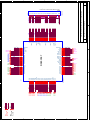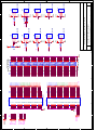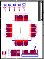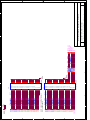
1
LDI Demonstration Kit User Manual N LDI Demonstration Kit User Manual (LVDS Display Interface) P/N LDI3V8BT-112 Rev 4.1 Interface Products Information contained in this document is subject to change National Semiconductor Corporation Interface Products LIT# LDI3V8BT-112-UM Date 04/04/01 Page 1 of 34 LDI Demonstration Kit User Manual Table of Contents INTRODUCTION ....................................................................................................................... 3 CONTENTS OF DEMO KIT ....................................................................................................... 4 APPLICATIONS ........................................................................................................................ 5 FEATURES AND EXPLANATIONS .......................................................................................... 6 TRANSMITTER .......................................................................................................................... 6 RECEIVER ............................................................................................................................... 7 HOW TO HOOK UP THE DEMO BOARDS (OVERVIEW) ........................................................ 8 POWER CONNECTIONS .......................................................................................................... 8 TRANSMITTER BOARD ........................................................................................................... 9 TX BOARD JUMPER DEFINITION ...............................................................................................10 TX BOARD JUMPER DEFAULT SETTINGS ...................................................................................11 LVDS MAPPING BY IDC CONNECTOR ......................................................................................12 Mapping for Old Mode.......................................................................................................12 Mapping for New Mode .....................................................................................................13 TX OPTIONAL: PARALLEL TERMINATION FOR TXIN ...................................................................14 BOM (BILL OF MATERIALS) .....................................................................................................15 RECEIVER BOARD..................................................................................................................16 RX BOARD JUMPER DEFINITION ...............................................................................................17 RX BOARD JUMPER DEFAULT SETTINGS ...................................................................................17 LVDS MAPPING BY IDC CONNECTOR ......................................................................................18 Mapping for Old Mode.......................................................................................................18 Mapping for New Mode .....................................................................................................19 RX OPTIONAL: SERIES TERMINATION FOR RXOUT ...................................................................20 BOM (BILL OF MATERIALS) .....................................................................................................21 JUMPER SETTING EXAMPLES 1 (OLD MODE).....................................................................22 18-BIT OR 24-BIT SINGLE PIXEL (OLD MODE)............................................................................22 18-BIT OR 24-BIT DUAL PIXEL (OLD MODE)...............................................................................23 JUMPER SETTING EXAMPLE 2 (NEW MODE) ......................................................................24 18-BIT OR 24-BIT SINGLE PIXEL (NEW MODE) ...........................................................................24 18-BIT OR 24-BIT DUAL PIXEL (NEW MODE)..............................................................................25 TROUBLESHOOTING..............................................................................................................26 ADDITIONAL INFORMATION..................................................................................................27 APPLICATION NOTES ...............................................................................................................27 3M 26-MINI D RIBBON CABLE AND CONNECTOR ........................................................................28 TRANSMITTER AND RECEIVER SCHEMATICS ..............................................................................35 National Semiconductor Corporation Interface Products LIT# LDI3V8BT-112-UM Date 04/04/01 Page 2 of 34 LDI Demonstration Kit User Manual Introduction National Semiconductor’s Interface Products Group LDI demo kit contains a Transmitter (Tx) demo board and a Receiver (Rx) demo board along with an interface cable. This kit will demonstrate the chipsets interfacing from a graphics controller using Low Voltage Differential Signaling (LVDS) to a Liquid Crystal Display (LCD) flat panel. The Transmitter board accepts 3V LVTLL/CMOS RGB signals from a graphics controller along with the clock and control signals. The LVDS Transmitter converts the LVTLL/CMOS parallel lines into serialized LVDS pairs. The serial data streams toggle at 3.5 times the clock speed. The Receiver board accepts the LVDS serialized data (and clock) and converts them back into parallel LVTLL/CMOS RGB signals for the Panel Timing Controller. The user needs to provide the proper RGB inputs to the Transmitter and also to provide a proper interface from the Receiver output to the panel timing controller. In some cases, a cable conversion board or harness scramble may be necessary depending on type of cable/connector interface used. Warnings: The maximum voltage that should ever be applied to the LDI Transmitter or Receiver Vcc is 4V. The Transmitter and Receiver power supply pins (Vccs) are NOT 5V tolerant. The Transmitter can however accept a 3.3V or 5V LVTLL/CMOS level on the inputs (TxIN). The Transmitter inputs are 5V tolerant. The maximum voltage that can be applied to any input pin is 5.0V. National Semiconductor Corporation Interface Products LIT# LDI3V8BT-112-UM Date 04/04/01 Page 3 of 34 LDI Demonstration Kit User Manual Contents of Demo Kit 1) One Transmitter board with IDC connectors on Tx input DS90C387MTD - 48 bit Transmitter 2) One Receiver board with IDC connectors on Rx output DS90CF388MTD - 48 bit Receiver 3) One 2-meter 3M MDR LVDS Cable interface to connect TxOUT to RxIN. Note: The MDR footprint has been set to accept a D26-1 pinout. 4) AN1127: LVDS Display Interface TFT Data Mapping 5) Demonstration Kit Documentation 6) DS90C387/DS90CF388 Datasheet *Note: The demo board trace layout is designed for minimum skew between channels. It is not absolutely required in most applications but be aware that the skew margins will be reduced if your board layout is not optimized. National Semiconductor Corporation Interface Products LIT# LDI3V8BT-112-UM Date 04/04/01 Page 4 of 34 LDI Demonstration Kit User Manual Applications Transmitter Board Receiver Board LCD Panel Digital RGB (TLL) from Graphics Controller LVDS Interface Cable Digital RGB (TLL) to Panel Contents of Demo kit Graphics Card AGP/PCI/ISA Bus Note: Demo Kit does not include the IDC cables, Graphics Card or Panel. LDI Application The diagram above illustrates the use of the Chipset (Tx/Rx) in a Host to LCD Panel Interface. Chipsets support up to 24-bit single pixel or 24-bit dual pixel AM-TFT LCD Panels for any VGA (640X480), SVGA (800X600), XGA (1024X768), SXGA (1280X1024), or UXGA (1600X1200). Because of the non-periodic nature of STN-DD SHFCLK, the Chipset may not work with all D-STN panels. The PLL CLK input of the Transmitter requires a free running periodic SHFCLK. Most Graphics Controller can provide a separate pin with a free running clock. In this case the STN-DD SHFCLK can be sent as Data while the free running clock can be used as SHFCLK for the PLL ref CLK. For example, C&T’s 65550’s WEC(Pin102) can be programmed to provide a free running clock using the BMP (Bios Modification Program). Please refer to STN Application using (AN-1056) for more information. Refer to the proper datasheet information on Chipsets (Tx/Rx) provided on each board for more detailed information. Note: Refer to AN-1127 for suggested mapping schemes. National Semiconductor Corporation Interface Products LIT# LDI3V8BT-112-UM Date 04/04/01 Page 5 of 34 LDI Demonstration Kit User Manual Features and Explanations Transmitter Pre-emphasis (PRE - pin 14/JP1): 1. This feature enables you to overcome cable capacitance through the LVDS interface. This function provides additional instantaneous current during switching transitions. NOTE: This function does NOT affect Rx output drive. 2. This function works in “Old Mode” or “New Mode”. 3. It affects Tx A0-A7 and CLKs LVDS outputs only. 4. To disable this function, pin 14 must be tied LOW. LVDS output drive will then be at its standard value of 3.5mA. 5. The input will be pulled low (0.7V) if no jumper is used. To adjust the level of preemphasis, place a jumper on JP1 to Vcc. R48 will now be connected. R48 is a 2K potentiometer. Use a number 1.4mm jewelers screwdriver to adjust R48. Turning clockwise will increase the pre-emphasis value. Turning counterclockwise will decrease the pre-emphasis value. R48 should be adjusted to reduce overshoot. Too much pre-emphasis can create an overshoot condition at the rising edge and an undershoot condition on the falling edge. Icc will increase but allows you to drive longer cables. Too little pre-emphasis will not allow you to drive longer cables. Monitor any one of the LVDS lines (A0-A7) or CLK1 for a visual confirmation of its effect. It is recommended that you monitor the LVDS signals with a differential probe. If a differential probe is not used, a single ended probe can be used for a quick check. PLL range select (PLLSEL - pin 15/JP5): 1. Auto-range is selected by tying pin 15 HIGH. 2. Low-range is selected by tying pin 15 LOW. 3. This function works in “Old Mode” or “New Mode”. Dual/Single Operation (DUAL - pin 23/JP7): 1. This feature provides three different modes of operation. The modes of operation are: 1) Dual 112MHz TxIN, Dual 112MHz TxOUT (pin 23 = HIGH; jumper JP7 to Vcc) 2) Single 170MHz TxIN, Dual 85MHz TxOUT (pin 23 = Vcc/2; no jumper on JP7) 3) Single 112MHz TxIN, Single 112MHz TxOUT (pin 23 = LOW; jumper JP7 to GND) 2. This function works in “Old Mode” or “New Mode” . 3. In Single to Single mode, TxOUT0 through TxOUT3 and associated Tx inputs are active. TxOUT4 through TxOUT7 and associated inputs are disabled to promote power savings on the part. DC Balance (BAL - pin 24/JP4): 1. This feature prevents charging of a cable in one state e.g. all “1s” or all “0s” for an extended period of time. The benefit to this is to “open” up the LVDS “eye-pattern” (Reducing the Inter-Symbol Interference). National Semiconductor Corporation Interface Products LIT# LDI3V8BT-112-UM Date 04/04/01 Page 6 of 34 LDI Demonstration Kit User Manual 2. This function works in “New Mode” ONLY. 3. It affects Tx A0-A7 and LVDS CLK outputs only. 4. To disable this function, pin 24 is tied LOW. To enable this function pin 24 is tied HIGH. 5. BAL (pin 6 of the Rx/JP6 on Rx board) must also be tied HIGH to enable this function. 6. In this mode, the part is NOT backward compatible with existing FPD-Link technology. This feature must be turned off to be backward compatible with current FPD-Link chipsets. NOTE: Refer to the “Application Notes” on back of the data sheet for complete description of each feature. Receiver PLL range select (PLLSEL - pin 5/JP5): 1. Auto-range is selected by tying pin 5 HIGH. 2. Low-range is selected by tying pin 5 LOW. DESKEW option (pin 4/JP4): 1. This function works in "New Mode" ONLY. 2. In order for the "DESKEW" feature to be operational (DESKEW=HIGH), a minimum of four clock cycles is required during blanking time. 3. To set "DESKEW" feature OFF, set jumper JP4 LOW. DC Balance (BAL - pin 6/JP6): 1. This feature prevents charging of a cable in one state e.g. all “1s” or all “0s” for an extended period of time. The benefit to this is to “open” up the LVDS “eye-pattern”. 2. This function works in “New Mode” ONLY. 3. To disable this function, pin 6 is tied LOW. To enable this function pin 6 is tied HIGH. 4. BAL (pin 24 of the Tx/JP4 on Tx board) must also be tied HIGH to enable this function. 5. In this mode, the chipset is NOT backward compatible with existing FPD-Link technology. This feature must be turned off to be backward compatible with current FPD-Link chipsets. NOTE: Refer to the “Application Notes” section on the back of the datasheet for complete description of each feature. National Semiconductor Corporation Interface Products LIT# LDI3V8BT-112-UM Date 04/04/01 Page 7 of 34 LDI Demonstration Kit User Manual How to hook up the demo boards (overview) The Tx demo board TxIN has been laid out to accept data from the Video Graphics card through two 50 pin IDC connectors. The TxOUT/RxIN interface uses the 3M MDR connector and 3M MDR cable with a D26-1 pin out. This combination provides minimal skew between LVDS channels. The receiver board RxOUT is laid out generically and must be mapped correctly to the panel being used. 1) Connect one end of the D26-1 MDR cable to the transmitter board and the other end to the receiver board. This is a standard pinout cable, longer lengths are available for purchase from 3M - see http://www.mmm.com 2) Jumpers have been configured from the factory (Refer to Tx and Rx "Jumper Default Settings" on pages 11 and 17) to run in normal mode with Deskew function OFF and with pre-emphasis ON. Jumpers are also provided on both boards so make sure that they are positioned correctly. See "Jumper Setting Examples" on page 22 and page 25 for different application configurations. 3) From the Graphics card, connect the appropriate IDC cable to the transmitter board and connect two 50-pin IDC cables from the receiver boards to the panel (Note: Refer to AN-1127 for suggested mapping schemes.) Note that pin 1 on the connector should be connected to pin 1 of the cable. 4) Power for the Tx and Rx boards are supplied externally through Test Pad (TP) TP1. Grounds for both boards are connected through TP2. 5) Turn on the PC first then power up the panel. Warning: Clock 2 is brought over to the Rx board through the USB pair, which are not matched in length with Clock 1, or LVDS data lines. Also the differential impedance of the USB pair is rated at 90 ohms. Power Connections The Transmitter and Receiver boards can only be powered by supplying power externally through TP1 (Vcc) and TP2 (GND). The maximum voltage that should ever be applied to the LDI Transmitter or Receiver Vcc is 4V. For the transmitter and the receiver to be operational, /PD must be tied to Vcc which is labeled as “JP3” and "JP1", respectively. Note: J4 on the Tx and J1 on the Rx provide the interface for LVDS signals. National Semiconductor Corporation Interface Products LIT# LDI3V8BT-112-UM Date 04/04/01 Page 8 of 34 LDI Demonstration Kit User Manual Transmitter Board Vcc and Gnd MUST be applied externally here J1 Pin 1 49 Pin 1 B27 B26 B25 B24 B23 B22 B21 OR B20 G27 G26 G25 G24 G23 G22 G21 G20 R27 R26 R25 R24 R23 R22 R21 R20 gnd gnd gnd gnd gnd gnd gnd gnd gnd gnd gnd gnd gnd gnd gnd gnd gnd gnd gnd gnd gnd gnd gnd gnd gnd gnd gnd gnd gnd gnd gnd gnd gnd gnd gnd gnd gnd gnd gnd gnd gnd gnd gnd gnd gnd gnd gnd gnd HSYNC VSYNC 49 DE J2 B17 B16 B15 B14 B13 B12 B11 B10 G17 G16 G15 G14 G13 G12 G11 G10 R17 R16 R15 R14 R13 R12 R11 R10 CLKIN 2 TxOUT LVDS signals 3M MDR26-1 Connector Pin 14 Pin 1 CLK2- CLK2+ GND A0- A0+ A1- A1+ A2- A2+ CLK1- CLK1+ GND 50 GND GND 2 GND A3- A3+ A4- A4+ A5- A5+ A6- A6+ A7- A7+ GND Pin 13 Pin 26 J4 BAL /PD R_FB DE PRE PLLSEL R_FDE DUAL 50 National Semiconductor Corporation Interface Products LIT# LDI3V8BT-112-UM Date 04/04/01 Page 9 of 34 LDI Demonstration Kit User Manual Tx Board Jumper Definition Jumper Purpose PRE (JP1) PRE-emphasis R_FB (JP2) Rising or Falling data strobe /PD (JP3) PowerDown BAL (JP4) DC BALance Settings = NONE GND Vcc GND Vcc (NONE: NO pre-emphasis; ON: pre-emphasis is adjusted through R48) When NO jumper is used, pre-emphasis is at 0.7V value. = Rising GND Vcc = Falling GND Vcc = OFF GND Vcc (OFF: Tx powers down; = ON GND Vcc ON: Tx is operational) = OFF = ON GND Vcc GND Vcc (Old Mode DC Balance OFF; New Mode DC Balance ON) PLLSEL PLL SELect (auto-range) (JP5) R_FDE (JP6) Rising or Falling Data Enable1 DUAL (JP7) DUAL/single mode 1 = ON = LOW = HIGH GND Vcc (LOW: auto-range OFF; GND Vcc HIGH: auto-range ON) = Rising GND Vcc = Falling GND = Single Vcc = Dual GND Vcc GND Vcc (When NO jumper is used, it is in Single to Dual Mode.) In Old Mode, the R_FDE pin is ignored by both the Tx and Rx when operating in Single (DUAL=LOW) or DUAL (DUAL=HIGH) mode. When the transmitter is operating in Single-to-Dual Mode (DUAL=1/2 Vcc), the R_FDE pin must be set HIGH if active data when DE signal is HIGH. In New Mode, R_FDE pins of both Tx and Rx boards MUST set to HIGH if DE signal is High during active data. R_FDE pins must set to LOW when DE signal is LOW during active data. National Semiconductor Corporation Interface Products LIT# LDI3V8BT-112-UM Date 04/04/01 Page 10 of 34 LDI Demonstration Kit User Manual Tx Board Jumper Default Settings The default setting for the Tx board is set to Old Mode, Dual-pixel mode and with preemphasis1. Jumper Name Purpose PRE PRE-Emphasis1 R_FB /PD BAL PLLSEL R_FDE DUAL 1 Settings Jumper Number JP1 GND Vcc GND Vcc GND Vcc GND Vcc GND Vcc GND Vcc GND Vcc Rising or Falling data strobe JP2 PowerDown JP3 DC BALance (Old Mode) JP4 PLL SELelect (auto-range) JP5 Rising or Falling Data Enable JP6 DUAL/single mode JP7 An adjustable potentiometer (2K ohm) is mounted at location R48. This allows preemphasis to be adjusted (only if JP1 has a jumper to VCC). Use a number 1.4mm jewelers screwdriver to adjust R48. Turning clockwise will increase the pre-emphasis value. Turning counterclockwise will decrease the pre-emphasis value. R48 should be adjusted to reduce overshoot. If no jumper is used, the pre-emphasis value will be 0.7V. See Tx Features and Explanations (Page 6) - Pre-Emphasis for description of feature. National Semiconductor Corporation Interface Products LIT# LDI3V8BT-112-UM Date 04/04/01 Page 11 of 34 LDI Demonstration Kit User Manual LVDS Mapping by IDC Connector The following two figures show how the Tx inputs are mapped to the IDC connector (It is also printed on the demo boards.) and to each of the eight LVDS channels. Note: Refer to AN-1127 for suggested mapping schemes. Mapping for Old Mode (Transmitter Board) 50-pin IDC Connector 50-pin IDC Connector Pin 1 49 B27 B26 B25 B24 B23 B22 B21 B20 G27 G26 G25 G24 G23 G22 G21 G20 R27 R26 R25 R24 R23 R22 R21 R20 gnd gnd gnd gnd gnd gnd gnd gnd gnd gnd gnd gnd gnd gnd gnd gnd gnd gnd gnd gnd gnd gnd gnd gnd gnd gnd 2 Pin 1 A6 A5 A7 A5 A4 A4 A2 50 49 J1 B17 B16 B15 B14 B13 B12 B11 B10 G17 G16 G15 G14 G13 G12 G11 G10 R17 R16 R15 R14 R13 R12 R11 R10 CLKIN gnd gnd gnd gnd gnd gnd gnd gnd gnd gnd gnd gnd gnd gnd gnd gnd gnd gnd gnd gnd gnd gnd HSYNC VSYNC DE 2 A2 A1 A3 A1 A0 A0 50 J2 CLK1 A0 G10 R15 R14 R13 R12 R11 R10 A1 B11 B10 G15 G14 G13 G12 G11 A2 DE VS YNC HSYNC B15 B14 B13 B12 B17 B16 G17 G16 R17 R16 A3 A4 G20 R25 R24 R23 R22 R21 R20 A5 B21 B20 G25 G24 G23 G22 G21 A6 CNTLF CNTLE B25 B24 B23 B22 A7 B27 B26 G27 G26 R27 R26 CLK2 Previous Cycle Curre nt Cycle National Semiconductor Corporation Interface Products LIT# LDI3V8BT-112-UM Date 04/04/01 Page 12 of 34 LDI Demonstration Kit User Manual Mapping for New Mode (Transmitter Board) IDC Connector 50-pin IDC Connector Pin 1 49 B27 B26 B25 B24 B23 B22 B21 B20 G27 G26 G25 G24 G23 G22 G21 G20 R27 R26 R25 R24 R23 R22 R21 R20 gnd gnd gnd gnd gnd gnd gnd gnd gnd gnd gnd gnd gnd gnd gnd gnd gnd gnd gnd gnd gnd gnd gnd gnd gnd gnd 2 Pin 1 A6 A7 A5 A4 B17 B16 B15 B14 B13 B12 B11 B10 G17 G16 G15 G14 G13 G12 G11 G10 R17 R16 R15 R14 R13 R12 R11 R10 CLKIN gnd gnd gnd gnd gnd gnd gnd gnd gnd gnd gnd gnd gnd gnd gnd gnd gnd gnd gnd gnd gnd gnd HSYNC VSYNC 50 49 DE J1 2 A2 A3 A1 A0 50 J2 CLK1 A0 R10 R11 R12 R13 R14 R15 DCBAL A1 G10 G11 G12 G13 G14 G15 DCBAL A2 B10 B11 B12 B13 B14 B15 DCBAL A3 R16 R17 G16 G17 B16 B17 DCBAL A4 R20 R21 R22 R23 R24 R25 DCBAL A5 G20 G21 G22 G23 G24 G25 DCBAL A6 B20 B21 B22 B23 B24 B25 DCBAL A7 R26 R27 G26 G27 B26 B27 DCBAL CLK2 Previous Cycle Current Cycle National Semiconductor Corporation Interface Products LIT# LDI3V8BT-112-UM Date 04/04/01 Page 13 of 34 LDI Demonstration Kit User Manual Tx Optional: Parallel Termination for TxIN On the Tx demo board, there are 50 inputs that have an 0402 pad on one side and the other side tied to ground. These pads are unpopulated from the factory but are provided if the user needs to adjust the input termination to match the impedance of the input signal. PAD1 TO PAD48 and PAD50 to PAD52 are associated with the Tx data input lines. PAD49 is associated with CLKIN. Mapping for Transmitter Inputs for the Optional Parallel Termination Resistors: Tx Pin Names R10 R11 R12 R13 R14 R15 R16 R17 G10 G11 G12 G13 G14 G15 G16 G17 B10 B11 B12 B13 B14 B15 B16 B17 R20 R21 Tx Pin Number 10 9 8 7 6 5 4 3 2 1 100 99 96 95 94 93 92 91 90 89 88 87 86 85 84 81 Parallel Termination Resistor PAD48 PAD47 PAD46 PAD45 PAD44 PAD43 PAD42 PAD41 PAD40 PAD39 PAD38 PAD37 PAD36 PAD35 PAD34 PAD33 PAD32 PAD31 PAD30 PAD29 PAD28 PAD27 PAD26 PAD25 PAD24 PAD23 Tx Pin Names R22 R23 R24 R25 R26 R27 G20 G21 G22 G23 G24 G25 G26 G27 B20 B21 B22 B23 B24 B25 B26 B27 DE VSYNC HSYNC CLKIN National Semiconductor Corporation Interface Products Tx Pin Number 80 79 78 77 76 75 74 73 72 71 70 69 66 65 64 63 62 61 60 59 58 57 56 55 54 11 Parallel Termination Resistor PAD22 PAD21 PAD20 PAD19 PAD18 PAD17 PAD16 PAD15 PAD14 PAD13 PAD12 PAD11 PAD10 PAD9 PAD8 PAD7 PAD6 PAD5 PAD4 PAD3 PAD2 PAD1 PAD50 PAD51 PAD52 PAD49 LIT# LDI3V8BT-112-UM Date 04/04/01 Page 14 of 34 LDI Demonstration Kit User Manual BOM (Bill of Materials) Bill of Materials LDI_112_MHz_Tx_Bom ======================================================================== Type Pattern Value Designators -----------------------------------------------------------------------------------------------------------------------------3M_MDR_D26-1 Qty = 1 3_PIN_HEADER Qty = 10 J4 .1" spacing JP1 JP2 JP3 JP4 JP5 JP6 JP7 JP8 JP9 JP10 25X2_IDC_CONN Qty = 2 J1 J2 PAD Qty = 52 0402 Optional (See previous page) PAD1 PAD2 PAD3 PAD4 PAD5 PAD6 PAD7 PAD8 PAD9 PAD10 PAD11 PAD12 PAD13 PAD14 PAD15 PAD16 PAD17 PAD18 PAD19 PAD20 PAD21 PAD22 PAD23 PAD24 PAD25 PAD26 PAD27 PAD28 PAD29 PAD30 PAD31 PAD32 PAD33 PAD34 PAD35 PAD36 PAD37 PAD38 PAD39 PAD40 PAD41 PAD42 PAD43 PAD44 PAD45 PAD46 PAD47 PAD48 PAD49 PAD50 PAD51 PAD52 CAP Qty = 2 CC0805 .001uF C4 C10 CAP Qty = 4 CC0805 .01uF C5 C6 C8 C11 CAP Qty = 5 CC0805 .1uF C1 C3 C7 C9 C12 DS90C387 Qty = 1 U1 POT Qty = 1 10Kohm R48 RES Qty = 7 10ohm R49 R50 R51 R52 R53 R54 R55 TESTPAD_.2"X.2" Qty = 2 CAP100P Qty = 4 TP1 TP2 CAP100P 10uF C2 C13 C14 C15 National Semiconductor Corporation Interface Products LIT# LDI3V8BT-112-UM Date 04/04/01 Page 15 of 34 LDI Demonstration Kit User Manual Receiver Board Vcc and Gnd MUST be applied externally here J3 50 R_FDE PowerDown (bar) Jumper RxIN LVDS signals 3M MDR26-1 connector Pin 26 Pin 13 GND A7+ A7- A6+ A6- A5+ A5- A4+ A4- A3+ A3- GND GND GND GND CLK1+ CLK1- A2+ A2- A1+ A1- A0+ A0- GND CLK2+ CLK2- Pin 14 2 50 Pin 1 DESKEW PLLSEL BAL 2 B27 B26 B25 B24 B23 B22 B21 B20 G27 G26 G25 G24 G23 G22 G21 G20 B27 B26 B25 B24 B23 B22 B21 B20 gnd B17 B16 B15 B14 B13 B12 B11 B10 G17 G16 G15 G14 G13 G12 G11 G10 R17 R16 R15 R14 R13 R12 R11 R10 CLKOUT gnd gnd gnd gnd gnd gnd gnd gnd gnd gnd gnd gnd gnd gnd gnd gnd gnd gnd gnd gnd gnd gnd gnd gnd gnd Pin 1 gnd gnd gnd gnd gnd gnd gnd gnd gnd gnd gnd gnd gnd gnd gnd gnd gnd gnd gnd 49 CNTLE/NC CNTLF/NC STOPCLK HSYNC VSYNC DE J4 National Semiconductor Corporation Interface Products 49 LIT# LDI3V8BT-112-UM Date 04/04/01 Page 16 of 34 Pin 1 LDI Demonstration Kit User Manual Rx Board Jumper Definition Jumper Purpose /PD (JP1) PowerDown R_FDE (JP2) Rising or Falling Data Enable Settings = OFF GND Vcc GND Vcc (OFF Tx powers down; ON Tx is operational) = Falling DESKEW DESKEW (JP4) GND Vcc GND Vcc = Rising GND Vcc GND Vcc = OFF PLLSEL PLL SELect (auto range) (JP5) BAL (JP6) = ON = ON = OFF GND = ON Vcc DC BALance GND = OFF Vcc = ON GND Vcc GND Vcc (Old Mode DC Balance OFF; New Mode DC Balance ON) Rx Board Jumper Default Settings Jumper Name Purpose /PD PowerDown – ON (Part R_FDE DESKEW PLLSEL BAL Settings Jumper Number JP1 is enabled) GND Vcc GND Vcc GND Vcc GND Vcc GND Vcc Rising or Falling Data Enable JP2 DESKEW JP4 PLL SELect (auto-range) JP5 DC BALance JP6 National Semiconductor Corporation Interface Products LIT# LDI3V8BT-112-UM Date 04/04/01 Page 17 of 34 LDI Demonstration Kit User Manual LVDS Mapping by IDC Connector The following two figures show how the Rx outputs are mapped to the IDC connector and to each of the eight LVDS channels. Note: Refer to AN-1127 for suggested mapping schemes. Mapping for Old Mode (Receiver Board) 50-pin IDC Connector 50-pin IDC Connector 50 A6 A5 A7 A5 A4 A4 2 B27 B26 B25 B24 B23 B22 B21 B20 G27 G26 G25 G24 G23 G22 G21 G20 B27 B26 B25 B24 B23 B22 B21 B20 gnd 50 49 gnd gnd gnd gnd gnd gnd gnd gnd gnd gnd gnd gnd gnd gnd gnd gnd gnd gnd gnd gnd gnd gnd gnd gnd gnd A2 A1 A3 A1 A0 A0 Pin 1 2 B17 B16 B15 B14 B13 B12 B11 B10 G17 G16 G15 G14 G13 G12 G11 G10 R17 R16 R15 R14 R13 R12 R11 R10 CLKOut J3 gnd gnd gnd gnd gnd gnd gnd gnd gnd gnd gnd gnd gnd gnd gnd gnd gnd gnd gnd 49 CNTLE/NC CNTLF/NC STOPCLK HSYNC VSYNC DE Pin 1 J4 CLK1 A0 G10 R15 R14 R13 R12 R11 R10 A1 B11 B10 G15 G14 G13 G12 G11 A2 DE VS YN C HSYN C B15 B14 B13 B12 B17 B16 G17 G16 R17 R16 A3 A4 G20 R25 R24 R23 R22 R21 R20 A5 B21 B20 G25 G24 G23 G22 G21 A6 C N TLF C N TLE B25 B24 B23 B22 A7 B27 B26 G27 G26 R27 R26 CLK2 P revious C ycle C urre nt C ycle National Semiconductor Corporation Interface Products LIT# LDI3V8BT-112-UM Date 04/04/01 Page 18 of 34 LDI Demonstration Kit User Manual Mapping for New Mode (Receiver Board) 50-pin IDC Connector 50-pin IDC Connector 50 A6 A7 A5 A4 2 B27 B26 B25 B24 B23 B22 B21 B20 G27 G26 G25 G24 G23 G22 G21 G20 B27 B26 B25 B24 B23 B22 B21 B20 gnd 50 49 gnd gnd gnd gnd gnd gnd gnd gnd gnd gnd gnd gnd gnd gnd gnd gnd gnd gnd gnd gnd gnd gnd gnd gnd gnd A2 A3 A1 A0 Pin 1 2 B17 B16 B15 B14 B13 B12 B11 B10 G17 G16 G15 G14 G13 G12 G11 G10 R17 R16 R15 R14 R13 R12 R11 R10 CLKOut J3 gnd gnd gnd gnd gnd gnd gnd gnd gnd gnd gnd gnd gnd gnd gnd gnd gnd gnd gnd 49 CNTLE/NC CNTLF/NC STOPCLK HSYNC VSYNC DE Pin 1 J4 CLK1 A0 R10 R11 R12 R13 R14 R15 DCBAL A1 G10 G11 G12 G13 G14 G15 DCBAL A2 B10 B11 B12 B13 B14 B15 DCBAL A3 R16 R17 G16 G17 B16 B17 DCBAL A4 R20 R21 R22 R23 R24 R25 DCBAL A5 G20 G21 G22 G23 G24 G25 DCBAL A6 B20 B21 B22 B23 B24 B25 DCBAL A7 R26 R27 G26 G27 B26 B27 DCBAL CLK2 Previous Cycle Current Cycle National Semiconductor Corporation Interface Products LIT# LDI3V8BT-112-UM Date 04/04/01 Page 19 of 34 LDI Demonstration Kit User Manual Rx Optional: Series Termination for RxOut On the Rx demo board there are 49 outputs that have an 0402 pad in series (but shorted). These pads are unpopulated from the factory but are provided if the user needs to adjust the output series termination to match the impedance of an input line the user must cut the short out before mounting a series resistor. R6-R12, R24-R37, R41-R70 are associated with the DATA input lines. R23 is associated with CLKOUT. Rx Pin Names R10 R11 R12 R13 R14 R15 R16 R17 G10 G11 G12 G13 G14 G15 G16 G17 B10 B11 B12 B13 B14 B15 B16 B17 R20 R21 R22 R23 Rx Pin Number 8 9 10 11 12 14 15 17 18 19 20 21 22 24 26 27 28 29 30 31 32 34 36 37 38 39 40 41 Parallel Termination Resistor R70 R31 R69 R32 R68 R33 R67 R34 R66 R35 R65 R36 R64 R37 R30 R63 R29 R62 R28 R61 R27 R60 R26 R59 R58 R25 R57 R24 Rx Pin Names R24 R25 R26 R27 G20 G21 G22 G23 G24 G25 G26 G27 B20 B21 B22 B23 B24 B25 B26 B27 DE VSYNC HSYNC STOPCLK CNTLF/NC CNTLE/NC 43 46 47 48 49 50 51 52 53 55 57 58 59 60 61 62 64 65 67 68 69 70 71 73 74 75 Parallel Termination Resistor R56 R55 R54 R53 R52 R51 R41 R12 R42 R11 R43 R10 R44 R9 R45 R8 R46 R7 R47 R6 R48 R5 R49 R4 R50 R3 CLKOUT 42 R23 National Semiconductor Corporation Interface Products Rx Pin Number LIT# LDI3V8BT-112-UM Date 04/04/01 Page 20 of 34 LDI Demonstration Kit User Manual BOM (Bill of Materials) Bill of Materials LDI_112_MHz_Rx_Bom ======================================================================== Type Pattern Value Designators -----------------------------------------------------------------------------------------------------------------------------2_PIN_HEADER .1" spacing JP3 Qty = 1 3M_MDR_D26--1 Qty = 1 3_PIN_HEADER Qty = 5 J2 .1" spacing JP1 JP2 JP4 JP5 JP6 25X2_IDC_R Qty = 2 PAD Qty = 6 J3 J4 0402 Shorted PAD1 PAD2 PAD3 PAD4 PAD5 PAD6 CAP Qty = 2 CC0805 .001uF C4 C10 Qty = 4 CC0805 .01uF C5 C6 C8 C11 Qty = 5 CC0805 .1uF C2 C3 C7 C9 C12 DS90CF388 Qty = 1 R0402 Qty = 55 U1 Optional (See previous page) R3 R4 R5 R6 R7 R8 R9 R10 R11 R12 R23 R24 R25 R26 R27 R28 R29 R30 R31 R32 R33 R34 R35 R36 R37 R41 R42 R43 R44 R45 R46 R47 R48 R49 R50 R51 R52 R53 R54 R55 R56 R57 R58 R59 R60 R61 R62 R63 R64 R65 R66 R67 R68 R69 R70 RES Qty = 10 100ohm R13 R14 R15 R16 R17 R18 R19 R20 R21 R22 Qty = 5 10ohm R1 R2 R38 R39 R40 TESTPAD_.2"X.2" Qty = 2 CAP100P Qty = 4 TP1 TP2 CAP100P 10uF C1 C13 C14 C15 National Semiconductor Corporation Interface Products LIT# LDI3V8BT-112-UM Date 04/04/01 Page 21 of 34 LDI Demonstration Kit User Manual Jumper Setting Examples 1 (Old Mode) The LDI chipset supports up to 24-bit single pixel and 24-bit dual pixel formats. The following examples show how to set the jumpers for a specific pixel format in Old Mode. WARNING 18-bit or 24-bit Single Pixel (Old Mode) The jumper settings below are for Old Mode, Single to Single pixel application. For Tx board: (For Rx board jumper settings in this application, see Rx Board Jumper Default Settings on page 17) Jumper Jumper Name Purpose Settings Number PRE R_FB /PD BAL PLLSEL R_FDE DUAL 1 PRE-Emphasis1 JP1 GND Vcc GND Vcc GND Vcc GND Vcc GND Vcc GND Vcc GND Vcc Rising or Falling data strobe JP2 PowerDown JP3 DC BALance JP4 PLL SELelect (auto-range) JP5 Rising or Falling Data Enable2 JP6 DUAL/single mode JP7 An adjustable potentiometer (2K ohm) is mounted at location R48. This allows preemphasis to be adjusted (only if JP1 has a jumper to VCC). Use a number 1.4mm jewelers screwdriver to adjust R48. Turning clockwise will increase the pre-emphasis value. Turning counterclockwise will decrease the pre-emphasis value. R48 should be adjusted to reduce overshoot. If no jumper is used, the pre-emphasis value will be 0.7V. See Tx Features and Explanations (Page 6) - Pre-Emphasis for description of feature. 2 In Old Mode, R_FDE can be set HIGH or LOW. Note: A) In the single pixel mode, only TxOUT0 through TxOUT3 (LVDS channels A0-A3) and their associated inputs are active. TxOUT4 through TxOUT7 and their associated inputs and CLK2 are disabled for power savings. B) "Old Mode" is backward compatible to existing FPD-Link technology. National Semiconductor Corporation Interface Products LIT# LDI3V8BT-112-UM Date 04/04/01 Page 22 of 34 LDI Demonstration Kit User Manual 18-bit or 24-bit Dual Pixel (Old Mode) (Default Setting from the factory) The jumper settings below are for Old Mode, Dual to Dual pixel application. For Tx board: (For Rx board jumper settings in this application, see Rx Board Jumper Default Settings on page 17) Jumper Jumper Name Purpose Settings Number PRE R_FB /PD BAL PLLSEL R_FDE DUAL PRE-Emphasis1 JP1 GND Vcc GND Vcc GND Vcc GND Vcc GND Vcc GND Vcc GND Vcc Rising or Falling data strobe JP2 PowerDown JP3 DC BALance JP4 PLL SELelect (auto-range) JP5 Rising or Falling Data Enable2 JP6 DUAL/single mode JP7 1 An adjustable potentiometer (2K ohm) is mounted at location R48. This allows preemphasis to be adjusted (only if JP1 has a jumper to VCC). Use a number 1.4mm jewelers screwdriver to adjust R48. Turning clockwise will increase the pre-emphasis value. Turning counterclockwise will decrease the pre-emphasis value. R48 should be adjusted to reduce overshoot. If no jumper is used, the pre-emphasis value will be 0.7V. See Tx Features and Explanations (Page 6) - Pre-Emphasis for description of feature. 2 In Old Mode, R_FDE can be set HIGH or LOW. National Semiconductor Corporation Interface Products LIT# LDI3V8BT-112-UM Date 04/04/01 Page 23 of 34 LDI Demonstration Kit User Manual Jumper Setting Example 2 (New Mode) The LDI chipset supports up to 24-bit single pixel and 24-bit dual pixel formats. The following examples show how to set the jumper for a specific pixel format in New Mode. 18-bit or 24-bit Single Pixel (New Mode) The jumper settings below are for New Mode, Single to Single pixel application. For Tx board: (The Rx board jumper settings in this application is the same as the Rx Board Jumper Default Settings on page 17 except the BAL pin(JP6), which must be set to Vcc.) Jumper Jumper Name Purpose Settings Number PRE R_FB /PD BAL PLLSEL R_FDE DUAL PRE-Emphasis1 JP1 GND Vcc GND Vcc GND Vcc GND Vcc GND Vcc GND Vcc GND Vcc Rising or Falling data strobe JP2 PowerDown JP3 DC BALance (New Mode) JP4 PLL SELelect (auto-range) JP5 Rising or Falling Data Enable2 JP6 DUAL/single mode JP7 1 An adjustable potentiometer (2K ohm) is mounted at location R48. This allows preemphasis to be adjusted (only if JP1 has a jumper to VCC). Use a number 1.4mm jewelers screwdriver to adjust R48. Turning clockwise will increase the pre-emphasis value. Turning counterclockwise will decrease the pre-emphasis value. R48 should be adjusted to reduce overshoot. If no jumper is used, the pre-emphasis value will be 0.7V. See Tx Features and Explanations (Page 6) - Pre-Emphasis for description of feature. 2 In Balanced Mode (New Mode), R_FDE pin (pin 21) MUST be set to HIGH if DE signal (pin 56) is HIGH during active data. R_FDE pin must set to LOW when DE signal is LOW during active data. Note: A) In the single pixel mode, only TxOUT0 through TxOUT3 (LVDS channels A0-A3) and their associated inputs are active. TxOUT4 through TxOUT7 and their associated inputs and CLK2 are disabled for power savings. National Semiconductor Corporation Interface Products LIT# LDI3V8BT-112-UM Date 04/04/01 Page 24 of 34 LDI Demonstration Kit User Manual 18-bit or 24-bit Dual Pixel (New Mode) The jumper settings below are for New Mode, Dual to Dual pixel application. For Tx Board: (The Rx board jumper settings in this application is the same as the Rx Board Jumper Default Settings on page 17 except the BAL pin(JP6), which must be set to Vcc.) Jumper Jumper Name Purpose Settings Number PRE R_FB /PD BAL PLLSEL R_FDE DUAL PRE-Emphasis1 JP1 GND Vcc GND Vcc GND Vcc GND Vcc GND Vcc GND Vcc GND Vcc Rising or Falling data strobe JP2 PowerDown JP3 DC BALance JP4 PLL SELelect (auto-range) JP5 Rising or Falling Data Enable2 JP6 DUAL/single mode JP7 1 An adjustable potentiometer (2K ohm) is mounted at location R48. This allows preemphasis to be adjusted (only if JP1 has a jumper to VCC). Use a number 1.4mm jewelers screwdriver to adjust R48. Turning clockwise will increase the pre-emphasis value. Turning counterclockwise will decrease the pre-emphasis value. R48 should be adjusted to reduce overshoot. If no jumper is used, the pre-emphasis value will be 0.7V. See Tx Features and Explanations (Page 6) - Pre-Emphasis for description of feature. 2 In Balanced Mode (New Mode), R_FDE pin (pin 21) MUST set to HIGH if DE signal (pin 56) is HIGH during active data. R_FDE pin must set to LOW when DE signal is LOW during active data. National Semiconductor Corporation Interface Products LIT# LDI3V8BT-112-UM Date 04/04/01 Page 25 of 34 LDI Demonstration Kit User Manual Troubleshooting If the demo boards are not performing properly, use the following as a guide for quick solutions to common problems. If the problem persists, contact the hotline number listed under Additional Information section of this document. Check the following: 1. Power and Ground are connected to both Tx AND Rx boards. 2. Supply voltage (typical 3.3V) and current (It's around 200mA with clock and one data bit at 66MHz.) are correct. 3. Input clock and input data (It's best to start with one data bit.) to the Tx board. 4. Jumpers are set correctly or to default settings. 5. The 2 meter cable is connecting the Tx and Rx boards. 6. Make sure all of the connections are good. 7. Start with a low clock frequency (40 or 66 MHz) and work from there. Trouble shooting chart: Problem… There is only the output clock. There is no output data. Solution… Make sure the data scramble/mapping is correct. Make sure there is data input. No output data and clock. Make sure Power is on. Input data and clock are active and connected correctly. Power, ground, input data and input clock are connected correctly, but no outputs. Make sure that the 2 meter cable is secured to both demo boards. Check the Power Down pins of both boards and make sure the devices are enabled (/PD=ON) for operation. The devices are pulling more than 1A of current. Check for shorts on the demo boards. After powering up the demo boards, the power supply reads less than 3V when it is set to 3.3V. Use a larger power supply that will provide enough current for the demo boards. National Semiconductor Corporation Interface Products LIT# LDI3V8BT-112-UM Date 04/04/01 Page 26 of 34 LDI Demonstration Kit User Manual Additional Information For more information on FPD-Link Transmitters/Receivers, refer to the National Semiconductor URL: http://www.national.com/appinfo/lvds Application Notes • • • • • • • • AN-971 An Overview of LVDS technology AN-1032 An Introduction to FPD-Link AN-1127 LVDS Display Interface TFT Data Mapping for Interoperability with FPD-Link AN-1163 TFT Data Mapping for Dual Pixel LDI Application - Alternate A - Color Map AN-1085 FPD-Link PCB and Interconnect Design-In Guidelines AN-977 LVDS Signal Quality: Jitter measurement using Eye pattern AN-1056 STN Application using FPD-Link AN-1059 High Speed Transmission with LVDS Devices Open LVDS Display Interface (OpenLDI) Specification: http://www.national.com/appinfo/fpd/0,2132,228,00.html SID'99 LDI Paper: http://www.national.com/appinfo/fpd/files/LDI_SID.pdf Information also available on the Internet: http://www.national.com/apnotes/Analog-FlatPanelDisplay.html http://www.national.com/appinfo/fpd/ Interface Hotline: The Interface Hotline number is: (408) 721-8500 National Semiconductor Corporation Interface Products LIT# LDI3V8BT-112-UM Date 04/04/01 Page 27 of 34 LDI Demonstration Kit User Manual 3M 26-Mini D Ribbon cable and connector The next few pages provide a full description of the cable and connector. For product request please contact 3M. 3M Cable and Connector Data is available at: http://www.mmm.com/Interconnects National Semiconductor Corporation Interface Products LIT# LDI3V8BT-112-UM Date 04/04/01 Page 28 of 34 LDI Demonstration Kit User Manual .050″ Mini D Ribbon (MDR) Connectors Surface Mount Right Angle Receptacle — Shielded 102XX-1210VE Series Surface mount right angle shielded I/O receptacle MDR digital LCD interface — 20 and 26 position Ultra-low signal skew design for high data rate transmission Ribbon type contact — industry preferred Reliable repetitive plugging/unplugging Latch design for easy use Positions: 14,20, 26, 40 and 50 Date Modified: August 2, 1999 TS-0755-06 Sheet 1 of 3 8 Physical Insulation Material: Flammability: Color: Contact Material: Plating Underplate: Wiping Area: Shroud and Latch Hook Material: Plating: Screw Lock Material: Plating: Marking: Glass Reinforced Polyester (PCT) UL 94V-0 Beige Copper Alloy (C521) 80 µ″ [2.0 µm] Nickel — QQ-N-290, Class 2 20 µ″ [0.50 µm] Min Gold — MIL-G-45204, Type II, Grade C Steel Nickel Copper Alloy (C521) Tin 3M Logo and Part Number Electrical Current Rating: 1 A Insulation Resistance: > 5 × 10⁸Ω at 500 VDC Withstanding Voltage: 500 Vrms for 1 Minute 3M Interconnect Solutions Division 6801 River Place Blvd. Austin, TX 78726-9000 For technical, sales or ordering information call 800-225-5373 National Semiconductor Corporation Interface Products LIT# LDI3V8BT-112-UM Date 04/04/01 Page 29 of 34 LDI Demonstration Kit User Manual .050″ Mini D Ribbon (MDR) Connectors Surface Mount Right Angle Receptacle — Shielded tact Con Contact Quantity Part 3M Part Number 14 10214-1210 VE 10220-1210 VE 10226-1210 VE 10240-1210 VE 10250-1210 VE 20 26 40 50 102XX-1210VE Series Dimensions A.008 B.006 C.006 D.006 E.006 1.16 [ 29.5 ] .93 [ 23.64 ] .47 [ 12.70 ] .33 [ 8.26 ] .50 [ 12.6 ] 1.32 [ 33.4 ] 1.081 [ 27.45 ] .650 [ 16.51 ] .475 [ 12.07 ] .646 [ 16.4 ] 1.50 [ 38.2 ] 1.231 [ 31.26 ] .800 [ 20.32 ] .625 [ 15.88 ] .795 [ 20.2 ] 1.85 [ 47.1 ] 1.581 [ 40.15 ] 1.150 [ 29.21 ] .975 [ 24.77 ] 1.150 [ 29.2 ] 2.06 [ 52.4 ] 1.831 [ 46.50 ] 1.400 [ 35.56 ] 1.225 [ 31.12 ] 1.40 [ 35.5 ] A position above last position last position 2X M2.5 Thread position below pos. 1 D .025 [ 0.635 ] position 2 .368 [ 9.35 ] position 1 .047 [ 1.20 ] .010 nom. [ 0.25 ] .394 [ 10.00 ] .187 [ 4.75 ] .19 [ 4.8 ] .203 [ 5.15 ] .138 [ 3.5 ] E B 2X M2.5 Thread (see note in ordering info) Position 1 .248 [ 6.30 ] .189 [ 4.80 ] Inch Position [mm] last position C Positioning Boss (2x) Tolerance Unless Noted .0 Inch ± .1 .00 .000 ± .01 ± .005 [ ] Dimensions for Reference only Ordering Information 102XX-1210VE Contact Quantity (See Table) Note: Use (M2.5x8mm) screws to mount to panel with max. thickness of 2.0 mm. TS-0755-06 Sheet 2 of 3 3M Interconnect Solutions Division 6801 River Place Blvd. Austin, TX 78726-9000 For technical, sales or ordering information call 800-225-5373 National Semiconductor Corporation Interface Products LIT# LDI3V8BT-112-UM Date 04/04/01 Page 30 of 34 LDI Demonstration Kit User Manual .050″ Mini D Ribbon (MDR) Connectors Surface Mount Right Angle Receptacle — Shielded Dimensions A ± .002 B ± .002 Contact Quantity 102XX-1210VE Series C ± .002 Recommended Board Layout 14 .930 [ 23.64 ] .500 [ 12.70 ] .325 [ 8.26 ] 20 1.081 [ 27.45 ] .650 [ 16.51 ] .475 [ 12.07 ] (viewed from connector side) 26 1.230 [ 31.26 ] .800 [ 20.32 ] .625 [ 15.88 ] 40 1.581 [ 40.15 ] 1.150 [ 29.21 ] .975 [ 24.77 ] 50 1.831 [ 46.50 ] 1.400 [ 35.56 ] 1.225 [ 31.12 ] Solder Pads for Solder Tail (See below for more detail) center spacing C .165 [ 4.2 ] center spacing .025 ± .0008 .016 ± .0004 .093 ± .0004 .118 [ 3.0 ] .110 ± .004 (2X) Screw Lock (see notes below) Lockstand Solder Pad Outline .122 [ 3.1 ] .138 [ 3.5 ] .256 [ 6.5 ] .187 max. [ 4.75 ] .088 [ 2.223 ] PCB Ref. Edge B A Solder Tail Layout Detail .079 + .004 (2X) – .000 Positioning Hole (#’s Correspond to Connector Contact # Shown on Previous Page) 7 14 Pos. Last Pos. 20 Pos. Last Pos. 6 14 13 Last Pos. 40 Pos. 12 4 11 3 10 2 1 9 Connector Position (Top Row) Position (Bottom Row) 8 PCB Ref. Edge 9 10 8 19 18 20 7 6 17 16 5 15 4 14 3 13 2 12 1 Connector Position (Top Row) Position (Bottom Row) 11 PCB Ref. Edge 13 26 Pos. 5 12 11 10 26 25 24 9 8 23 22 21 7 6 5 4 3 2 Connector Position (Top Row) 1 20 19 18 17 16 15 14 Position (Bottom Row) PCB Ref. Edge 20 19 18 17 16 15 14 13 12 Last 40 39 38 Pos. 11 10 9 8 7 6 5 4 3 2 1 Connector Position 37 36 35 34 33 32 31 30 29 28 27 26 25 24 23 22 21 Position (Bottom Row) PCB Ref. Edge 50 Pos. Last Pos. 25 24 23 22 21 20 19 18 17 16 15 14 13 12 11 10 9 8 7 6 5 4 3 2 1 50 49 48 47 46 45 44 43 42 41 40 39 38 37 36 35 34 33 32 31 30 29 28 27 26 Connector Position Position (Bottom Row) PCB Ref. Edge Recommended Panel Cut-out Contact Quantity D E 14 1.10 [ 19.9 ] .931 [ 23.64 ] 20 .94 [ 23.8 ] 1.081 [ 27.45 ] 26 1.09 [ 27.6 ] 1.231 [ 31.26 ] 40 1.44 [ 36.5 ] 1.581 [ 40.15 ] 50 1.69 [ 42.8 ] 1.830 [ 46.50 ] **Notes: 1. Plated through holes for .062″ board thickness. 2. Use mounting screws ( M2.5 ) to fasten to board. Note: Panel thickness .079 [ 2.00 ] Max. .319 ± .004 [ 8.1 ] R .060 [ 1.50 ] D ± .004 E ± .004 TS-0755-06 Sheet 3 of 3 3M Interconnect Solutions Division 6801 River Place Blvd. Austin, TX 78726-9000 For technical, sales or ordering information call 800-225-5373 National Semiconductor Corporation Interface Products LIT# LDI3V8BT-112-UM Date 04/04/01 Page 31 of 34 LDI Demonstration Kit User Manual .050″ Mini D Ribbon (MDR) Cable Assembly High Speed Digital Data Transmission System — 26 Position 14526-EZHB-XXX-0QC 10 shielded pairs plus 4 individual wires The solution for high speed datacom and telecom applications Each differential pair is shielded with foil; entire cable bundle is shielded with foil and braid Rugged MDR ribbon type contact Quick release latches Date Modified: February 23, 2000 TS-0891-05 Sheet 1 of 3 91 Physical Connector Contact Plating Wiping Area: Shell Color: Material: Cable Color: Jacket Material: Flammability: 30µ″ [ 0.76µm ] Min. Gold Parchment/Beige Acrylonitrile Butadiene Styrene (ABS) Parchment/Beige Polyvinyl Chloride (PVC) AWM VW-1 Electrical Voltage Rating: 30 V Current Rating: 1 A Insulation Resistance: > 1 × 10⁸Ω at @100 Vdc Withstanding Voltage: 350 Vrms for 1 minute Individually Shielded Twisted Pairs Characteristic Impedance: 100 ± 10Ω (USB 90Ω) Conductor Size: 28 AWG Stranded Propogation Velocity: 1.25 ns/ft [4.1 ns/m ] Environmental Temperature Rating: –20°C to +75°C UL File No.: E86982 3M Interconnect Solutions Division 6801 River Place Blvd. Austin, TX 78726-9000 For technical, sales or ordering information call 800-225-5373 National Semiconductor Corporation Interface Products LIT# LDI3V8BT-112-UM Date 04/04/01 Page 32 of 34 LDI Demonstration Kit User Manual .050″ Mini D Ribbon (MDR) Cable Assembly High Speed Digital Data Transmission System — 26 Position 14526-EZHB-XXX-0QC 26 Position High Density Mini D Ribbon (MDR) Male Plug 26 Position High Density Mini D Ribbon (MDR) Male Plug Cable ( See wiring diagram for cable construction ) 2X Squeeze Release Latches 2X Squeeze Release Latches Length (See ordering information) 1 14 2 3 4 15 16 17 5 18 6 7 8 9 10 19 20 21 22 23 11 24 12 13 25 26 MDR 26 Position Plug ( Both Ends ) Ordering Information 14526-EZHB-XXX-0QC Length 100 = 1 meter 200 = 2 meter 500 = 5 meter A00 = 10 meter TS-0891-05 Sheet 2 of 3 3M Interconnect Solutions Division 6801 River Place Blvd. Austin, TX 78726-9000 For technical, sales or ordering information call 800-225-5373 National Semiconductor Corporation Interface Products LIT# LDI3V8BT-112-UM Date 04/04/01 Page 33 of 34 LDI Demonstration Kit User Manual 3M - Preliminary LDI Cable Rev A 3/3/99 Assembly Specification Cable: v24.0 Connector: Plug type 10126-6000 D26-1 wiring diagram for cable assembly and board layout MDR 26 position right angle surface mount receptacle 10226-1210 VE Note: "pad" column represents actual position of solder pad on board layout. "pin #" column specifies corresponding receptacle contact #. ** Note: Temporary pinout for LDI testing purposes only.** Transmitter-387 pin # Transmitter receptacle pad pin # signal type Cable Assembly Receiver receptacle signal type pin # pad Receiver-388 pin # 1 Extra 1 LVDS gnd 26 14 Extra 2 A7P 13 79 2 Extra 3 A7M 25 80 50 15 A0M A6P 12 82 49 3 A0P A6M 24 83 47 16 A1M A5P 11 84 46 4 A1P A5M 23 85 45 17 A2M A4P 10 86 44 5 A2P A4M 22 87 42 18 CLK1M A3P 9 89 41 6 CLK1P A3M 21 90 19 Control 1 Control 4 8 7 Control 2 Control 3 20 20 Control 3 Control 2 7 8 Control 4 Control 1 19 39 21 A3M CLK1P 6 91 38 9 A3P CLK1M 18 92 37 22 A4M A2P 5 94 36 10 A4P A2M 17 95 34 23 A5M A1P 4 96 33 11 A5P A1M 16 97 32 24 A6M A0P 3 98 31 12 A6P A0M 15 99 29 25 A7M Extra 3 2 28 13 A7P Extra 2 14 26 LVDS gnd Extra 1 1 National Semiconductor Corporation Interface Products LIT# LDI3V8BT-112-UM Date 04/04/01 Page 34 of 34 1 2 3 4 GND LVDS_GND PLL_GND A GND LVDS_GND PLL_GND VCC LVDS_VCC PLL_VCC G13 G12 R20 B17 B16 B15 B14 B13 B12 B11 B10 G17 G16 G15 G14 R26 R25 R24 R23 R22 R21 R26 R25 R24 R23 R22 R21 VCC GND R20 B17 B16 B15 B14 B13 B12 B11 B10 G17 G16 G15 G14 VCC GND G13 G12 B R26 R25 R24 R23 R22 R21 VCC GND R20 B17 B16 B15 B14 B13 B12 B11 B10 G17 G16 G15 G14 VCC GND G13 G12 DS90C387 76 77 78 79 80 81 82 83 84 85 86 87 88 89 90 91 92 93 94 95 96 97 98 99 100 U1 R27 G20 G21 G22 G23 G24 G25 DS90C387 G11 G10 R17 R16 R15 R14 R13 R12 R11 R10 CLKIN VCC LVDS_VCC PLL_VCC C C PRE PLLSEL B G26 G27 B20 B21 B22 B23 B24 B25 B26 B27 DE VSYNC HSYNC R27 G20 G21 G22 G23 G24 G25 GND VCC G26 G27 B20 B21 B22 B23 B24 B25 B26 B27 DE VSYNC HSYNC VCC GND LVDS_GND 75 74 73 72 71 70 69 68 67 66 65 64 63 62 61 60 59 58 57 56 55 54 53 52 51 R27 G20 G21 G22 G23 G24 G25 GND VCC G26 G27 B20 B21 B22 B23 B24 B25 B26 B27 DE VSYNC HSYNC VCC GND LVDSGND G11 G10 R17 R16 R15 R14 R13 R12 R11 R10 CLKIN PLLVCC GND PRE PLLSEL PLLGND PLLGND PLLVCC PLLGND R_FB R_FDE /PD DUAL BAL LVDSGND 1 2 3 4 5 6 7 8 9 10 11 12 13 14 15 16 17 18 19 20 21 22 23 24 25 G11 G10 R17 R16 R15 R14 R13 R12 R11 R10 CLKIN PLL_VCC GND PRE PLLSEL PLL_GND PLL_GND PLL_VCC PLL_GND R_FB R_FDE /PD DUAL BAL LVDS_GND R_FB R_FDE /PD DUAL BAL A 50 49 48 47 46 45 44 43 42 41 40 39 38 37 36 35 34 33 32 31 30 29 28 27 26 Date: Size Title A0M A0P LVDSVCC A1M A1P A2M A2P LVDSGND CLK1M CLK1P LVDSVCC A3M A3P A4M A4P LVDSGND A5M A5P A6M A6P LVDSVCC A7M A7P CLK2M/NC CLK2P/NC LVDS_GND A3M A3P A4M A4P A5M A5P A6M A6P A7M A7P A0M A0P A1M A1P A2M A2P CLK1M CLK1P CLK2M/NC CLK2P/NC 26 position 27 28 1 14 2 15 3 16 4 17 5 18 6 19 7 20 8 21 9 22 10 23 11 24 12 25 13 26 J4 E D Tuesday, August 28, 2001 Document Number LDI3V8BT-112 Tx REV 4 schematic Sheet E 1 Demo Board schematic: LDI3V8BT-112 - TRANSMITTER A0M A0P LVDS_VCC A1M A1P A2M A2P LVDS_GND CLK1M CLK1P LVDS_VCC A3M A3P A4M A4P LVDS_GND A5M A5P A6M A6P LVDS_VCC A7M A7P CLK2M/NC CLK2P/NC D of NOTE: - Pins 27 and 28 ties the Screw Lock to ground 3 Rev 1 1 2 3 4 1 2 3 4 A R_FDE DUAL DE VSYNC HSYNC PRE R_FB /PD BAL PLLSEL VCC GND HSYNC VSYNC DE R_FDE DUAL DE VSYNC HSYNC PRE R_FB /PD BAL PLLSEL VCC GND GND HSYNC VSYNC DE GND 2 4 6 8 10 12 14 16 18 20 22 24 26 28 30 32 34 36 38 40 42 44 46 48 50 2 4 6 8 10 12 14 16 18 20 22 24 26 28 30 32 34 36 38 40 42 44 46 48 50 IDC2X25_Shrouded 1 3 5 7 9 11 13 15 17 19 21 23 25 27 29 31 33 35 37 39 41 43 45 47 49 J2 IDC2X25_Shrouded 1 3 5 7 9 11 13 15 17 19 21 23 25 27 29 31 33 35 37 39 41 43 45 47 49 J1 B B17 B16 B15 B14 B13 B12 B11 B10 G17 G16 G15 G14 G13 G12 G11 G10 R17 R16 R15 R14 R13 R12 R11 R10 CLKIN B27 B26 B25 B24 B23 B22 B21 B20 G27 G26 G25 G24 G23 G22 G21 G20 R27 R26 R25 R24 R23 R22 R21 R20 GND B B17 B16 B15 B14 B13 B12 B11 B10 G17 G16 G15 G14 G13 G12 G11 G10 R17 R16 R15 R14 R13 R12 R11 R10 CLKIN B27 B26 B25 B24 B23 B22 B21 B20 G27 G26 G25 G24 G23 G22 G21 G20 R27 R26 R25 R24 R23 R22 R21 R20 B27 B26 B25 B24 B23 B22 B21 B20 G27 G26 G25 G24 G23 G22 G21 G20 R27 R26 R25 R24 R23 R22 R21 R20 B17 B16 B15 B14 B13 B12 B11 B10 G17 G16 G15 G14 G13 G12 G11 G10 R17 R16 R15 R14 R13 R12 R11 R10 CLKIN DE VSYNC HSYNC C PAD1 PAD2 PAD3 PAD4 PAD5 PAD6 PAD7 PAD8 PAD9 PAD10 PAD11 PAD12 PAD13 PAD14 PAD15 PAD16 PAD17 PAD18 PAD19 PAD20 PAD21 PAD22 PAD23 PAD24 PAD25 PAD26 PAD27 PAD28 PAD29 PAD30 PAD31 PAD32 PAD33 PAD34 PAD35 PAD36 PAD37 PAD38 PAD39 PAD40 PAD41 PAD42 PAD43 PAD44 PAD45 PAD46 PAD47 PAD48 PAD49 PAD50 PAD51 PAD52 0ohm 0ohm 0ohm 0ohm 0ohm 0ohm 0ohm 0ohm 0ohm 0ohm 0ohm 0ohm 0ohm 0ohm 0ohm 0ohm 0ohm 0ohm 0ohm 0ohm 0ohm 0ohm 0ohm 0ohm 0ohm 0ohm 0ohm 0ohm 0ohm 0ohm 0ohm 0ohm 0ohm 0ohm 0ohm 0ohm 0ohm 0ohm 0ohm 0ohm 0ohm 0ohm 0ohm 0ohm 0ohm 0ohm 0ohm 0ohm 0ohm 0ohm 0ohm 0ohm NOTE: OPEN C GND VCC R55 10ohm R52 10ohm R50 10ohm Date: Size Title D 3-PIN_HEADER D Thursday, August 23, 2001 Document Number LDI3V8BT-112 Tx REV 4 schematic Sheet 2 GND E of 3 Rev 1 3-PIN_HEADER 1 2 3 HSYNC 3-PIN_HEADER 1 2 3 JP9 3-PIN_HEADER 1 2 3 JP8 3-PIN_HEADER JP10 VCC GND VSYNC VCC GND DE VCC GND 1 2 3 JP7 3-PIN_HEADER 1 2 3 DUAL R54 10ohm R53 10ohm VCC GND JP5 3-PIN_HEADER 1 2 3 JP4 3-PIN_HEADER 1 2 3 JP3 3-PIN_HEADER 1 2 3 JP2 3-PIN_HEADER 1 2 3 R51 10ohm JP6 R_FDE 1 2 3 VCC E JP1 Demo Board schematic: LDI3V8BT-112 - INPUTS GND VCC GND VCC GND VCC GND VCC GND PRE PLLSEL R49 10ohm BAL /PD R_FB GND R48 SVR20K A CW CCW 1 2 3 4 A 0.001uF 0.01uF 0.1uF B C10 C9 C11 0.001uF 0.01uF 0.1uF C8 0.1uF C7 GND C2 10uF C4 0.01uF 0.01uF + C3 C6 C5 C1 0.1uF + + C15 10uF C14 10uF 0.1uF C12 + C13 10uF C Title Demo Board schematic: LDI3V8BT-112 - POWER 3 E of 3 Rev 1 3 4 Date: Size D Thursday, August 23, 2001 Document Number LDI3V8BT-112 Tx REV 4 schematic Sheet E 1 PLL_GND PLL_VCC LVDS_GND LVDS_VCC GND VCC TESTPAD_.2"X.2" 1 TP2 TESTPAD_.2"X.2" VCC D 1 GND LVDS_GND PLL_GND VCC PLL_VCC LVDS_VCC C 2 GND GND LVDS_GND PLL_GND VCC LVDS_VCC PLL_VCC TP1 1 B 1 2 2 3 4 VCC A 1 2 1 2 1 2 1 2 3 4 GND LVDS_GND PLL_GND 27 28 26 13 25 12 24 11 23 10 22 9 21 8 20 7 19 6 18 5 17 4 16 3 15 2 14 1 26 position J2 A7P A7M A6P A6M A5P A5M A4P A4M A3P A3M CLK1P CLK1M A2P A2M A1P A1M A0P A0M A LVDS_GND R22 100ohm CLK1P CLK1M A2P A2M A1P A1M A0P A0M A7P A7M A6P A6M A5P A5M A4P A4M A3P A3M R13 100ohm R14 100ohm R15 100ohm R16 100ohm R17 100ohm R18 100ohm R19 100ohm R20 100ohm R21 100ohm NOTE: MOUNT TERMINATION RESISTORS NEXT TO DEVICE GND LVDS_GND PLL_GND 2-PIN_HEADER 1 2 JP3 LVDS_GND R_FDE /PD A7P A7M LVDS_VCC A6P A6M A5P A5M A4P A4M LVDS_GND A3P A3M CLK1P CLK1M LVDS_VCC A2P A2M A1P A1M A0P A0M LVDS_GND LVDSGND R_FDE /PD A7P A7M LVDSVCC A6P A6M A5P A5M A4P A4M LVDSGND A3P A3M CLKP CLKM LVDSVCC A2P A2M A1P A1M A0P A0M LVDSGND B DS90CF388 76 77 78 79 80 81 82 83 84 85 86 87 88 89 90 91 92 93 94 95 96 97 98 99 100 U1 B25 B24 HSYNC VSYNC DE B27 B26 DS90CF388 R10 R11 R12 R13 R14 VCC LVDS_VCC PLL_VCC C C R15 R16 B B23 B22 B21 B20 G27 G26 A G25 R17 G10 G11 G12 G13 G14 VCC LVDS_VCC PLL_VCC NOTE: - Pins 27 and 28 ties the Screw Lock to ground G24 G23 G22 CNTLE_NC CNTLF_NC STOPCLK CNTLE_NC CNTLF_NC STOPCLK GND HSYNC VSYNC DE B27 B26 VCC B25 B24 GND B23 B22 B21 B20 G27 G26 VCC G25 GND G24 G23 G22 75 74 73 72 71 70 69 68 67 66 65 64 63 62 61 60 59 58 57 56 55 54 53 52 51 CNTLE/NC CNTLF/NC STOPCLK GND HSYNC VSYNC DE B27 B26 VCC B25 B24 GND B23 B22 B21 B20 G27 G26 VCC G25 GND G24 G23 G22 PLLGND PLLVCC PLLGND DESKEW PLLSEL BAL GND R10 R11 R12 R13 R14 VCC R15 R16 GND R17 G10 G11 G12 G13 G14 VCC G15 GND 1 2 3 4 5 6 7 8 9 10 11 12 13 14 15 16 17 18 19 20 21 22 23 24 25 PLL_GND PLL_VCC PLL_GND DESKEW PLLSEL BAL GND R10 R11 R12 R13 R14 VCC R15 R16 GND R17 G10 G11 G12 G13 G14 VCC G15 GND G15 G21 G20 R27 R26 R25 VCC GND R24 CLKOUT R23 R22 R21 R20 B17 B16 GND B15 VCC B14 B13 B12 B11 B10 G17 G16 Date: Size Title 50 49 48 47 46 45 44 43 42 41 40 39 38 37 36 35 34 33 32 31 30 29 28 27 26 G21 G20 R27 R26 R25 VCC GND R24 CLKOUT R23 R22 R21 R20 B17 B16 GND B15 VCC B14 B13 B12 B11 B10 G17 G16 B14 B13 B12 B11 B10 G17 G16 B15 R24 CLKOUT R23 R22 R21 R20 B17 B16 G21 G20 R27 R26 R25 R38 10ohm DESKEW BAL GND VCC GND VCC GND VCC GND R40 10ohm R39 10ohm R2 10ohm R_FDE VCC GND R1 10ohm /PD PLLSEL D Tuesday, August 28, 2001 Document Number LDI3V8BT-112 Rx REV 4 schematic Sheet E VCC E 1 Demo Board schematic: LDI3V8BT-112 - RECEIVER D of 3 Rev 1 3-PIN_HEADER 1 2 3 JP6 3-PIN_HEADER 1 2 3 JP5 3-PIN_HEADER 1 2 3 JP4 3-PIN_HEADER 1 2 3 JP2 3-PIN_HEADER 1 2 3 JP1 1 2 3 4 1 2 3 4 VCC GND R6 R47 R7 R46 R8 R45 R9 R44 R10 R43 R11 R42 R12 R41 R51 R52 R53 R54 R55 R56 R24 R57 R25 R58 0ohm 0ohm 0ohm 0ohm 0ohm 0ohm 0ohm 0ohm 0ohm 0ohm 0ohm 0ohm 0ohm 0ohm 0ohm 0ohm 0ohm 0ohm 0ohm 0ohm 0ohm 0ohm 0ohm 0ohm B27 B26 B25 B24 B23 B22 B21 B20 G27 G26 G25 G24 G23 G22 G21 G20 R27 R26 R25 R24 R23 R22 R21 R20 GND B17 B16 B15 B14 B13 B12 B11 B10 G17 G16 G15 G14 G13 G12 G11 G10 R17 R16 R15 R14 R13 R12 R11 R10 CLKOUT A R59 R26 R60 R27 R61 R28 R62 R29 R63 R30 R37 R64 R36 R65 R35 R66 R34 R67 R33 R68 R32 R69 R31 R70 R23 0ohm 0ohm 0ohm 0ohm 0ohm 0ohm 0ohm 0ohm 0ohm 0ohm 0ohm 0ohm 0ohm 0ohm 0ohm 0ohm 0ohm 0ohm 0ohm 0ohm 0ohm 0ohm 0ohm 0ohm 0ohm B17 B16 B15 B14 B13 B12 B11 B10 G17 G16 G15 G14 G13 G12 G11 G10 R17 R16 R15 R14 R13 R12 R11 R10 CLKOUT NOTE: SHORTED INTENTIONALLY CUT TO SEPARATE B27 B26 B25 B24 B23 B22 B21 B20 G27 G26 G25 G24 G23 G22 G21 G20 R27 R26 R25 R24 R23 R22 R21 R20 VCC GND A 49 47 45 43 41 39 37 35 33 31 29 27 25 23 21 19 17 15 13 11 9 7 5 3 1 49 47 45 43 41 39 37 35 33 31 29 27 25 23 21 19 17 15 13 11 9 7 5 3 1 B GND GND CNTLE_NC CNTLF_NC STOPCLK HSYNC VSYNC DE IDC2X25_Shrouded 50 48 46 44 42 40 38 36 34 32 30 28 26 24 22 20 18 16 14 12 10 8 6 4 2 J4 IDC2X25_Shrouded 50 48 46 44 42 40 38 36 34 32 30 28 26 24 22 20 18 16 14 12 10 8 6 4 2 J3 B PAD1 PAD2 PAD3 PAD4 PAD5 PAD6 0 ohm 0 ohm 0 ohm 0 ohm 0 ohm 0 ohm R3 R50 R4 R49 R5 R48 C C 0ohm 0ohm 0ohm 0ohm 0ohm 0ohm CNTLE_NC CNTLF_NC STOPCLK HSYNC VSYNC DE Thursday, September 06, 2001 Date: D Document Number LDI3V8BT-112 Rx REV 4 schematic Sheet Demo Board schematic: LDI3V8BT-112 - OUTPUTS Size Title D 2 E E of 3 Rev 1 1 2 3 4 A 0.001uF 0.01uF 0.1uF B C10 C9 C11 0.001uF 0.01uF 0.1uF C8 0.1uF C7 GND C1 10uF C4 0.01uF 0.01uF + C3 C6 C5 C2 0.1uF + + C15 10uF C14 10uF 0.1uF C12 + C13 10uF C Title Demo Board schematic: LDI3V8BT-112 - POWER 3 E of 3 Rev 1 3 4 Date: Size D Tuesday, August 28, 2001 Document Number LDI3V8BT-112 Rx REV 4 schematic Sheet E 1 PLL_GND PLL_VCC LVDS_GND LVDS_VCC GND VCC TESTPAD_.2"X.2" 1 TP2 TESTPAD_.2"X.2" VCC D 1 GND LVDS_GND PLL_GND VCC PLL_VCC LVDS_VCC C 2 GND GND LVDS_GND PLL_GND VCC LVDS_VCC PLL_VCC TP1 1 B 1 2 2 3 4 VCC A 1 2 1 2 1 2