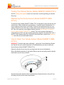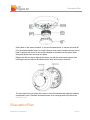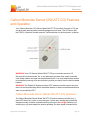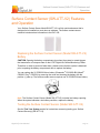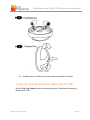
1
] Digital Life User Guide ATT-UM-V3-201501 Product Number: ATT-UM-V3-201501 ©2015 AT&T Intellectual Property. AT&T, the Globe and AT&T DIGITAL LIFE logos are trademarks of AT&T Intellectual Property. All rights reserved. Safety Instructions FCC Regulations The following FCC Regulations apply to most, if not all, 915MHz and 433MHz devices: This device complies with part 15 of the FCC Rules. Operation is subject to the following two conditions: (1) This device may not cause harmful interference, and (2) this device must accept any interference received, including interference that may cause undesired operation. This device has been tested and found to comply with the limits for a Class B digital device, pursuant to Part 15 of the FCC Rules. These limits are designed to provide reasonable protection against harmful interference in a residential installation. This equipment generates, uses and can radiate radio frequency energy and, if not installed and used in accordance with the instructions, may cause harmful interference to radio communications. However, there is no guarantee that interference will not occur in a particular installation. If this equipment does cause harmful interference to radio or television reception, which can be determined by turning the equipment off and on, the user is encouraged to try to correct the interference by one or more of the following measures: Reorient or relocate the receiving antenna. Increase the separation between the equipment and receiver. Connect the equipment into an outlet on a circuit different from that to which the receiver is connected. Consult the dealer or an experienced radio/TV technician for help. Changes or modifications not expressly approved by the party responsible for compliance could void the user‘s authority to operate the equipment. The antenna(s) used for this transmitter must not be co-located or operating in conjunction with any other antenna or transmitter. FCC Compliance Statement for UL Certification The following is the FCC Compliance Statement as it applies to UL Certification: This device complies with FCC Rules and Regulations as Part 15 devices as well as Industry Canada Rules and Regulations. Operation is subject to the following two (2) conditions: This device may not cause harmful intereference. This device must accept any interference received, including interference that may cause undesired operation. RF Exposure Information Digital Life User Manual Page ii Safety Instructions This device meets the government’s requirements for exposure to radio waves. This device is designed and manufactured not to exceed the emission limits for exposure to radio frequency (RF) energy set by the Federal Communications Commission of the U.S. Government. This device complies with FCC radiation exposure limits set forth for an uncontrolled environment. In order to avoid the possibility of exceeding the FCC radio frequency exposure limits, human proximity to the antenna shall not be less than 20cm (8 inches) during normal operation. Important Information About Radio Devices The following information is important when installing radio (wireless) devices: 1. AT&T radio controls provide a reliable communications link and fill an important need in portable wireless signaling. However, there are some limitations which must be observed. 2. For US installations only: the radios are required to comply with FCC rules and regulations including FCC part 15 devices. As such, they have limited transmitter power and therefore limited range. 3. A receiver cannot respond to more than one transmitted signal at a time and may be blocked by radio signals that occur on or near their operating frequencies regardless of code settings. 4. Changes or modifications to the device may void FCC compliance 5. Infrequently used radio links should be tested regularly to protect against undetected interference or fault. 6. RF signals can be affected by metal objects including metal doors or large mirrors. Care should be taken to avoid these objects during installation as they can interfere with proper operation. WARNING! The polarity of the battery must be observed. Improper handling of lithium batteries may result in heat generation, explosion or fire, which may lead to personal injuries. Replace only with the same as recommended by the manufacturer. Use of another battery may present a risk of fire or corrosion. CAUTION: Batteries should not be recharged, disassembled in heat above 100ºC (212ºF) or disposed of in fire. Disposal of used batteries must be made in accordance with the waste recovery and recycling regulations in your area. Notice to users in California─This Perchlorate warning applies only to Manganese Dioxide Lithium cells sold or distributed only in California, USA. Percolate Material special handling may apply. See www.dtsc.gov.hazardouswaste/perchlorate. Digital Life User Manual Page iii Safety Instructions 1. Read these instructions. 2. Keep these instructions. 3. Heed all warnings. 4. Follow all instructions. 5. Do not use this apparatus near water. 6. Clean only with dry cloth. 7. Do not block any ventilation openings. Install in accordance with the manufacturer's instructions. 8. Do not install near any heat sources such as radiators, heat registers, stoves, or other apparatus (including amplifiers) that produce heat. 9. Do not defeat the safety purpose of the polarized or grounding-type plug. A polarized plug has two blades with one wider than the other. A grounding-type plug has two blades and a third grounding prong. The wide blade or the third prong is provided for your safety. If the provided plug does not fit into your outlet, consult an electrician for replacement of the obsolete outlet. 10. Protect the power cord from being walked on or pinched particularly at plugs, convenience receptacles, and the point where they exit from the apparatus. 11. Only use attachments/accessories specified by the manufacturer. 12. Use only with the cart, stand, tripod, bracket, or table specified by the manufacturer, or sold with the apparatus. When a cart is used, use caution when moving the cart/apparatus combination to avoid injury from tip-over. 13. Refer all servicing to qualified service personnel. Servicing is required when the apparatus has been damaged in any way, such as a power-supply cord or plug is damaged, liquid has been spilled or objects have fallen into the apparatus, the apparatus has been exposed to rain or moisture, does not operate normally, or has been dropped. Power Source Warning A label on this product indicates the correct power source for this product. Operate this product only from an electrical outlet with the voltage and frequency indicated on the product label. If you are uncertain of the type of power supply to your home or business, consult your service provider or your local power company. The AC inlet on the unit must remain accessible and operable at all times. Ground the Product Digital Life User Manual Page iv Safety Instructions WARNING! Avoid electric shock and fire hazard! If this product connects to coaxial cable wiring, be sure the cable system is grounded (earthed). Grounding provides some protection against voltage surges and built-up static charges. Verify the Power Source from the On/Off Power Light When the on/off power light is not illuminated, the apparatus may still be connected to the power source. The light may go out when the apparatus is turned off, regardless of whether it is still plugged into an AC power source. Eliminate AC Mains Overloads WARNING! Avoid electric shock and fire hazard! Do not overload AC mains, outlets, extension cords, or integral convenience receptacles. For products that require battery power or other power sources to operate them, refer to the operating instructions for those products. Protect from Exposure to Moisture and Foreign Objects WARNING! Avoid electric shock and fire hazard! Do not expose this product to dripping or splashing liquids, rain, or moisture. Objects filled with liquids, such as vases, should not be placed on this apparatus. WARNING! Avoid electric shock and fire hazard! Unplug this product before cleaning. Do not use a liquid cleaner or an aerosol cleaner. Do not use a magnetic/static cleaning device (dust remover) to clean this product. WARNING! Avoid electric shock and fire hazard! Never push objects through the openings in this product. Foreign objects can cause electrical shorts that can result in electric shock or fire. Service Warnings WARNING! Avoid electric shock! Do not open the cover of this product. Opening or removing the cover may expose you to dangerous voltages. If you open the cover, your warranty will be void. This product contains no userserviceable parts. Check Product Safety Upon completion of any service or repairs to this product, the service technician must perform safety checks to determine that this product is in proper operating condition. Protect the Product When Moving It Digital Life User Manual Page v Safety Instructions Always disconnect the power source when moving the apparatus or connecting or disconnecting cables. Battery Replacement Warnings WARNING: The battery(ies) used in each device may present a fire or chemical burn hazard if mistreated. Do not recharge, disassemble, heat above 100°C (212°F) or dispose of in fire. Replace battery(ies) with specified manufacturer batteries only. Use of another battery(ies) may present a risk of fire or explosion." System Test It is recommended that you test your Digital Life System on a weekly basis. Digital Life User Manual Page vi Contents Introduction to the Digital Life System ........................................................................................ 1 About Your AT&T Digital Life System ..................................................................................... 2 AT&T Digital Life Central Monitoring Centers ......................................................................... 2 Digital Life Customer Care Technical Support ........................................................................ 2 Creating/Changing Your Security PIN ................................................................................. 2 Changing the Entry Delay Timer ......................................................................................... 3 Changing the Exit Delay Timer ............................................................................................ 3 Digital Life System Devices ........................................................................................................ 4 Digital Life Controller (DLC-100) Features and Operation ................................................................... 9 Digital Life Controller (DLC-100) Features .............................................................................. 9 Digital Life Controller (DLC-100) Operation ...........................................................................10 Replacing the Digital Life Controller (DLC-100) Battery .........................................................11 Keypad Features and Operation ...............................................................................................13 Keypad (SW-ATT-PAD2W) Features and Operation .........................................................................14 Becoming Familiar with your Keypad Model SW-ATT-PAD2W Features ...............................14 Display ...............................................................................................................................15 System LIGHTs..................................................................................................................15 Numeric Keypad ................................................................................................................15 Function Buttons ................................................................................................................15 Emergency Buttons ............................................................................................................15 Operating Your Keypad Model SW-ATT-PAD2W ..................................................................15 Ready to Arm .....................................................................................................................16 Not Ready to Arm ..............................................................................................................16 Arming the System .............................................................................................................17 Arming the System-STAY ..............................................................................................17 Arming the System-INSTANT ........................................................................................18 Arming the System-AWAY.............................................................................................19 Arming the System- BYPASS ........................................................................................20 Disarming the System – Entry Delay ..................................................................................21 Disarming the System ........................................................................................................22 Alarm Sounding-Cancel Alarm ...........................................................................................23 Digital Life User Manual Page viii Contents Sending a Fire Emergency Alarm.......................................................................................24 Sending an Auxiliary Emergency Alarm .............................................................................25 Sending a Police Emergency Alarm ...................................................................................26 Keypad Model SW-ATT-PAD2W Operation Quick Reference................................................27 Replacing the Keypad (Model SW-ATT-PAD2W) Batteries ...................................................27 Keypad (Model SW-ATT-PAD2W) and Indoor Siren (Model SW-ATT-SRN) Sounds .............28 Priority of Alarm Signaling .....................................................................................................30 Sounding and Displaying Device Trouble Conditions .............................................................30 Keypad (SR-KPD02) Features and Operation ...........................................................................31 Becoming Familiar with your Keypad Model SR-KPD02 Features .........................................32 Display ...............................................................................................................................32 System LIGHTs..................................................................................................................33 Numeric Keypad ................................................................................................................33 Function Buttons ................................................................................................................33 Emergency Buttons ............................................................................................................33 Operating Your Keypad Model SR-KPD02 ............................................................................33 Ready to Arm .....................................................................................................................33 Not Ready to Arm ..............................................................................................................34 Arming the System .............................................................................................................34 Arming the System-AWAY.............................................................................................35 Arming the System-STAY ..............................................................................................36 Arming the System-INSTANT ........................................................................................37 Arming the System-BYPASS .........................................................................................38 Disarming the System – Entry Delay ..................................................................................39 Disarming the System ........................................................................................................40 Alarm Sounding-Cancel Alarm ...........................................................................................42 Alarm Cancelled – Not Sent (Performed before Entry/Exit Delay Timeout) ........................44 Sending a Fire Emergency Alarm.......................................................................................45 Sending an Auxiliary Emergency Alarm .............................................................................46 Sending a Police Emergency Alarm ...................................................................................47 Keypad Model SR-KPD02 Operation Quick Reference..........................................................48 Digital Life User Manual Page ix Contents Replacing the Keypad (Model SR-KPD02) Batteries .............................................................48 Keypad Model SR-KPD02 and Siren Model SW-ATT-SRN Sounds.......................................50 Priority of Alarm Signaling .....................................................................................................52 Sounding and Displaying Device Trouble Conditions .............................................................52 Keychain Remote(s) Features and Operation ...........................................................................54 Keychain Remote (Model SW-ATT-FOB) Operation ..............................................................54 Keychain Remote (Model SW-ATT-FOB) Function Buttons ...................................................55 Replacing the Keychain Remote (Model SW-ATT-FOB) Batteries .........................................56 Keychain Remote (Model SW-ATT-FOB2) Operation ............................................................58 Keychain Remote (Model SW-ATT-FOB2) Function Buttons .................................................59 Replacing the Keychain Remote (Model SW-ATT-FOB2) Batteries .......................................60 Indoor Siren (SW-ATT-SRN) Features and Operation...............................................................62 Indoor Siren (Model SW-ATT-SRN) Operation ......................................................................62 Replacing the Indoor Siren (Model SW-ATT-SRN) Batteries .................................................63 Smoke Sensor Features and Operation ....................................................................................64 Smoke Sensor (SW-ATT-SMKT) Features ............................................................................65 Smoke Sensor (Model SW-ATT-SMKT) Operation ................................................................65 Replacing the Smoke Sensor (Model SW-ATT-SMKT) Batteries ...........................................65 Testing Your Smoke Sensor (Model SW-ATT-SMKT) ...........................................................66 Maintaining the Smoke Sensor (Model SW-ATT-SMKT)........................................................66 Smoke Sensor (562NSTT-OEM-ATT01) Features.................................................................67 Smoke Sensor (Model 562NSTT-OEM-ATT01) Operation ....................................................67 Replacing the Smoke Sensor (Model 562NSTT-OEM-ATT01) Batteries ...............................67 Testing Your Smoke Sensor (Model 562NSTT-OEM-ATT01) ................................................69 Maintaining the Smoke Sensor (Model 562NSTT-OEM-ATT01) ............................................69 How to Clean Your Smoke Sensor (Model 562NSTT-OEM-ATT01) ......................................69 Evacuation Plan ........................................................................................................................70 Avoiding Fire Hazards ...........................................................................................................71 What to do in Case of Fire .....................................................................................................71 Always be Prepared ..............................................................................................................71 Carbon Monoxide Sensor (SW-ATT-CO) Features and Operation .....................................................73 Carbon Monoxide Sensor (Model SW-ATT-CO) Operation ....................................................73 Digital Life User Manual Page x Contents Replacing the CO Sensor (Model SW-ATT-CO) Batteries .....................................................75 Testing the CO Sensor (Model SW-ATT-CO) ........................................................................76 Maintaining the CO Sensor (Model SW-ATT-CO) ..................................................................76 Troubleshooting the CO Sensor (Model SW-ATT-CO)...........................................................76 Surface Contact Sensor (SW-ATT-V2) Features and Operation.........................................................77 Replacing the Surface Contact Sensor (Model SW-ATT-V2) Battery .....................................77 Testing the Surface Contact Sensor (Model SW-ATT-V2) .....................................................77 Recessed Contact Sensor (SW-ATT-RDW) Features and Operation...........................................................78 Replacing the Recessed Contact Sensor (Model SW-ATT-RDW) Battery .............................78 Testing the Recessed Contact Sensor (Model SW-ATT-RDW)..............................................79 Glass Break Sensor (SW-ATT-GB) Features and Operation .....................................................80 Replacing the Glass Break Sensor (Model SW-ATT-GB) Batteries .......................................80 Testing the Glass Break Detector (Model SW-ATT-GB) ........................................................81 Motion Sensor (SW-ATT-PIR) Features and Operation.............................................................82 Replacing the Motion Sensor (Model SW-ATT-PIR) Battery ..................................................82 Testing the PIR Motion Sensor (Model SW-ATT-PIR)............................................................83 Signal Booster 915 (SW-ATT-RPTR9) Features and Operation ................................................84 Replacing the Signal Booster (915) (Model SW-ATT-RPTR9) Batteries ................................85 Signal Booster 433 (SW-ATT-RPTR4) Features and Operation ................................................86 Replacing the Signal Booster (433) (Model SW-ATT-RPTR4) Batteries ................................86 Conversion Kit (SW-ATT-TAKF) Features and Operation .........................................................88 Replacing the Conversion Kit (Model SW-ATT-TAKRF) Batteries .........................................89 CP-01-2010 Supported Features for False Alarm Reduction.....................................................90 Testing Your System .................................................................................................................94 Digital Life System Testing Instructions .................................................................................94 Digital Life User Manual Page xi Introduction to the Digital Life System Introduction to the Digital Life System T HANK YOU FOR CHOOSING AT&T DIGITAL LIFE for Life Safety Services. Our Life Safety Services include UL Certified fire and intrusion monitoring services. These are end-to-end AT&T services and the underlying AT&T Digital Life Service Architecture includes: AT&T Digital Life System which is professionally installed in your home for alarm detection. AT&T Cellular Data Service for alarm reporting. AT&T Central Monitoring Centers with dedicated agents for handling alarms and contacting Emergency Services. As an option, AT&T Digital Life also offers Life Style Services, which includes a wide range of home automation and control services. Please go to www.att.com/digitallife to learn about Digital Life – Life Style Services. Digital Life User Manual Page 1 Introduction to the Digital Life System About Your AT&T Digital Life System Your professionally installed AT&T Digital Life System (DLS) features a Digital Life Controller (DLC-100), which is typically installed in a closet, utility room or basement. The DLC-100 is a wireless controller that monitors a wide range of AT&T provided devices for the detection of fire, such as smoke sensors and carbon monoxide (CO) sensors. The DLC-100 does not monitor previously installed smoke and CO sensors or customer provided smoke and CO sensors; nor does it monitors previously installed intrusion devices. Once the DLC-100 is installed and activated, it constantly monitors smoke sensors and CO sensors and automatically reports alarms to the AT&T Digital Life Central Monitoring Centers. When the system is armed, the DLC-100 automatically reports intrusion (AT&T provided window/door sensors, motion sensors and glass breakage sensors) alarms to the AT&T Digital Life Central Monitoring Centers. AT&T Digital Life Central Monitoring Centers The AT&T Digital Life Central Monitoring Centers are state-of-the-art, 24x7, UL Certified monitoring facilities, where all agents are dedicated to handling and processing alarms. Digital Life Customer Care Technical Support Digital Life Customer Care Technical Support agents are available 24x7 to provide any assistance that you require, including: Establishing/changing your mandatory four (4) digit Security PIN Changing your Entry Delay Timer setting Changing your Exit Delay Timer setting In order to speak with a Digital Life Customer Care Technical Support agent, please call 1-855-288-2727 and when prompted press number four (4) to speak with an agent: Active Alarm, press (1) New Service, press (2) Questions About Your Bill, press (3) Customer Care Technical Support, press (4) Creating/Changing Your Security PIN A Digital Life Customer Care Technical Support agent can assist you in creating or changing your mandatory four (4) digit Security PIN. A Security PIN must be established before you will be able to arm and disarm your system. You can also create/change your Security PIN by accessing www.att.com/dlpin. Digital Life User Manual Page 2 Introduction to the Digital Life System Changing the Entry Delay Timer A Digital Life Customer Care Technical Support agent can assist you in changing your Entry Delay Timer Interval. The Entry Delay Timer Interval feature allows you sufficient time to get to a keypad and enter your Security PIN before the system sounds an alarm. The default setting is thirty (30) seconds. You have a range of thirty (30) seconds to four minutes (240 seconds) for your Entry Delay Timer Interval setting. Changing the Exit Delay Timer A Digital Life Customer Care Technical Support agent can assist you in changing your Exit Delay Timer Interval. The Exit Delay Timer Interval feature allows you sufficient time to exit your home without tripping an alarm. The default setting is sixty (60) seconds. You have a range of sixty (60) seconds to two minutes (120 seconds) for your Exit Delay Timer Interval setting. Digital Life User Manual Page 3 Digital Life System Devices Digital Life System Devices Your Digital Life System includes a combination of two or more of these devices: Device… See… Digital Life Controller (DLC-100) Digital Life Controller Model DLC100 Features and Operation, page 9 Keypad (SW-ATT-PAD2W) Keypad Model SW-ATT-PAD2W Features and Operation, page 14 Keypad (SR-KPD02) Keypad Model SR-KPD02 Features and Operation, page 31 Digital Life User Manual Page 4 Digital Life System Devices Device… See… Keychain Remote (SW-ATT-FOB) Keychain Remote Model SW-ATTFOB Features and Operation, page 54 Keychain Remote (SW-ATT-FOB2) Keychain Remote Model SW-ATTFOB2 Features and Operation, page 58 Indoor Siren (SW-ATT-SRN) Indoor Siren Model SW-ATT-SRN Features and Operation, page 62 Digital Life User Manual Page 5 Digital Life System Devices Device… See… Smoke Sensor (SW-ATT-SMKT) Smoke Sensor Model SW-ATTSMKT Features and Operation, page 65 Smoke Sensor (56N2TT-OEM-ATT01) Smoke Sensor Model 56N2TTOEM-ATT01 Features and Operation, page 67 Carbon Monoxide Sensor (SW-ATTCO) Carbon Monoxide Sensor Model SW-ATT-CO Features and Operation, page 73 Surface Contact Sensor (SW-ATT-V2) Surface Contact Sensor Model SW-ATT-V2 Features and Operation, page 77 Digital Life User Manual Page 6 Digital Life System Devices Device… See… Recessed Contact Sensor (SW-ATTRDW) Recessed Contact Sensor Model SW-ATT-RDW Features and Operation, page 78 Glass Break Sensor (SW-ATT-GB) Glass Break Sensor Model SWATT-GB Features and Operation, page 80 Motion Sensor (SW-ATT-PIR) Motion Sensor Model SW-ATT-PIR Features and Operation, page 82 Digital Life User Manual Page 7 Digital Life System Devices Device… See… Signal Booster 915 (SW-ATT-RPTR9) Signal Booster 915 Model SWATT-RPTR9 Features and Operation, page 84 Signal Booster 433 (SW-ATT-RPTR4) Signal Booster 433 Model SWATT-RPTR4 Features and Operation, page 86 Conversion Kit (SW-ATT-TAKRF) Conversion Kit Model SW-ATTTAKRF Features and Operation, page 88 Digital Life User Manual Page 8 Digital Life Controller (DLC-100) Features and Operation Digital Life Controller (DLC-100) Features and Operation Your Digital Life System comes with a Digital Life Controller Model DLC-100 that communicates with every AT&T provided device within your Digital Life System configuration. Your Digital Life Technician has installed your DLC-100 in a closet, utility room or basement. Digital Life Controller (DLC-100) Features 1. AT&T Cellular Data Antenna 2. Antenna for communication with AT&T smoke, carbon monoxide and intrusion detection devices 3. Antenna for communication with keypads and indoor sirens 4. Antenna for communication with AT&T smoke, carbon monoxide and intrusion detection devices 5. Five System Status LIGHTs 6. Battery Compartment Door Digital Life User Manual Page 9 Digital Life Controller (DLC-100) Features and Operation Digital Life Controller (DLC-100) Operation The five (5) System LIGHTs on the DLC-100 door provide the following at-a-glance status: FEATURE OPERATION AC POWER FLASHING GREEN LIGHT indicates your DLC is powering up GREEN LIGHT indicates DLC is operational LIGHT OFF indicates LOCAL POWER FAILURE Note During LOCAL POWER FAILURE the BATTERY, SYSTEM and WIRELESS BROADBAND lights will be FLASHING GREEN. Wireline Broadband data will not be operating. BATTERY SYSTEM Digital Life User Manual GREEN LIGHT indicates the battery is fully charged RED LIGHT indicates the battery needs to be replaced LIGHT OFF indicates the battery is dead or there is no battery GREEN LIGHT indicates your system is working RED LIGHT indicates your system has a problem YELLOW LIGHT indicates your system is in Maintenance Mode YELLOW LIGHT FLASHING then GREEN LIGHT FLASHING indicates Radio Frequency (RF) jamming is being detected Type of RF Jamming SYSTEM LIGHT Behavior One-Way Jamming at DLC-100 Digital Life Controller Cabinet SYSTEM LIGHT blinks yellow once, blinks green once then repeats Two-Way Jamming at DLC-100 Digital Life Controller Cabinet SYSTEM LIGHT blinks yellow once, blinks green twice then repeats One-Way Jamming at a Repeater SYSTEM LIGHT blinks yellow once, blinks green three (3) times then repeats Two-Way Jamming at a Repeater SYSTEM LIGHT blinks yellow once, blinks green four (4) times then repeats Page 10 Digital Life Controller (DLC-100) Features and Operation FEATURE OPERATION WIRELESS BROADBAND GREEN LIGHT indicates signal strength is good RED indicates no or low cellular data signal strength GREEN LIGHT indicates data connection LIGHT OFF indicates no data connection WIRELINE BROADBAND WARNING! If the SYSTEM LIGHT is flashing Yellow and then flashes Green and an auditory signal is coming from the Digital Life Controller Cabinet (DLC-100), the DLC100 is detecting Radio Frequency (RF) Jamming. Please call 1-855-288-2727 for Customer Care Technical Support. Replacing the Digital Life Controller (DLC-100) Battery CAUTION: Opening the battery compartment door when the system is armed triggers the transmission of a tamper alarm to the AT&T Digital Life Central Monitoring Center. In order to prevent a false alarm, please ensure that the system is disarmed prior to opening the battery compartment door to replace the battery. To replace the battery: 1. Make sure that the system is disarmed before opening the battery compartment door to replace the battery. 2. Open the battery compartment by inserting a small coin or the blade of a small flat screwdriver into the slot on the battery compartment screw and rotate onequarter turn to release the door. 3. Press the release tab on the Faston Tab to remove and disconncet the discharged battery from the DLC-100. Note This step applies to battery replacement only. Digital Life User Manual Page 11 Digital Life Controller (DLC-100) Features and Operation 4. Take the new battery and align the DLC-100 Faston terminal with the battery Faston connector and snap to lock. Note Typically, the DLC battery comes with terminal connectors pre-installed; however, if your DLC battery does not include pre-installed terminal connectors check the installation package kit for the Faston Tab and attach the RED connector to the RED terminal and the BLACK connector to the BLACK terminal. 5. Insert the battery into the battery compartment and lift the handle to secure. Make sure to properly tuck in battery wires, to avoid squeezing them between the door and frame. CAUTION: Ensure to properly insert the battery wires into the battery compartment to AVOID squeezing the battery wires between the compartment door and the frame. 6. Insert the small coin or blade of a small flat screw driver into the slot on the Battery Compartment screw and rotate counterclockwise one-quarter turn to secure the door. Digital Life User Manual Page 12 Keypad Features and Operation Keypad Features and Operation Your Digital Life System includes one or more, or a combination of the following keypads: Keypad Model SW-ATT-PAD2W Keypad Model SR-KPD02 Digital Life User Manual Page 13 Keypad (SW-ATT-PAD2W) Features and Operation Keypad (SW-ATT-PAD2W) Features and Operation Your Keypad Model SW-ATT-PAD2W enables you to control basic system functions, such as arming and disarming your Digital Life System. The keypad includes an LCD, which displays system status information, and features a built-in sounder that announces system status information. It makes predefined “chirp” and “beep” sounds when buttons are pressed on the keypad or specific events occur. For example, the system can be configured so the keypad chirps when an entry/exit door is opened and closed. The keypad makes different sounds for fire alarms and intrusion alarms. The Keypad Model SW-ATT-PAD2W is powered by an AC/DC adapter that plugs into an AC power outlet. It is equipped with batteries that provide 24-hour battery backup under a local power failure condition. The batteries are customer replaceable. Becoming Familiar with your Keypad Model SW-ATTPAD2W Features Digital Life User Manual Page 14 Keypad (SW-ATT-PAD2W) Features and Operation Display The LCD displays the current system state and any changes in system state. System LIGHTs If the Armed (Red) LIGHT is ON, a LCD message will indicate the status of the System: Armed-STAY or Armed-AWAY. If the Ready (Green) LIGHT is ON, the system is ready for arming. If the Armed (Red) LIGHT is OFF and the Ready (Green) LIGHT is OFF, then the system is not ready for arming because one or more of the monitored devices, such a door or window sensor, is not in the closed state. Numeric Keypad Use the Numeric keypad to enter your Security PIN to confirm emergency button selections, and to access system functions. Function Buttons You can use the function buttons to select the STAY, AWAY and BYPASS features. Emergency Buttons The Emergency Buttons are used to send an emergency alarm directly to AT&T Digital Life Central Monitoring Center immediately upon being pressed and confirmed. The Emergency Buttons are functional whether the system is armed or not armed. Operating Your Keypad Model SW-ATT-PAD2W The Keypad Model SW-ATT-PAD2W is used to arm/disarm the system and obtain information concerning the status of the system. The system has three (3) primary states: Ready to Arm – all of the supervised devices are in the closed state Not Ready to Arm – one, or more, of the supervised devices is not in the closed state Armed – system is in the Armed–AWAY or Armed–STAY mode Digital Life User Manual Page 15 Keypad (SW-ATT-PAD2W) Features and Operation Ready to Arm The system is ready to be armed when the READY (Green) LIGHT is on and no message is displayed on the LCD. Not Ready to Arm The system is not ready to arm because one, or more, of the supervised devices is not in the closed state and indicate “Devices Not Ready.” Afterwards, the keypad will display the name of the open state device(s) and cycle through the device list if there are multiple devices. Each open state device will display on a separate line. Digital Life User Manual Page 16 Keypad (SW-ATT-PAD2W) Features and Operation Arming the System Before you can arm your system, all the devices must be closed. If some devices are currently open, the READY (Green) light will be off. Before you try to arm your system, close all doors and windows, and make sure no one is present in areas with motion sensors. Arming the System-STAY Press the STAY button to arm the perimeter sensors only. The system starts an exit delay timer interval. The keypad beeps and the LCD displays “Arming - Exit Now.” Initially, the keypad beeps slowly during the exit delay timer interval and then chirps fast for the last ten (10) seconds. If you choose to exit while Arming – STAY, you should exit through the designated entry/exit door(s) before the exit delay timer interval expires. After the exit delay timer interval expires, the system is in the Armed-STAY mode. The ARMED (Red) LIGHT is illuminated and the LCD displays “Armed - STAY.” If you open a non-designated entry/exit door or window while the system is in Armed-STAY mode, it will cause an alarm. Note You may disarm the system during the exit delay timer interval by entering your four (4) digit Security PIN. Digital Life User Manual Page 17 Keypad (SW-ATT-PAD2W) Features and Operation Arming the System-INSTANT Press and hold the STAY button for two (2) seconds to arm all perimeter and interior sensors. The keypad chirps and the LCD displays “Arming - Exit Now”. The system is in the Armed-STAY mode. The ARMED (Red) LIGHT is illuminated and the LCD displays “Armed - STAY”. When the system is ArmedSTAY, if you open a non-designated entry/exit door or window it will cause an alarm. Note You may disarm the system by entering your four (4) digit Security PIN. Digital Life User Manual Page 18 Keypad (SW-ATT-PAD2W) Features and Operation Arming the System-AWAY Press the AWAY button to arm all of the sensors, including perimeter and interior sensors. The system generates an exit delay timer interval. The keypad beeps and the LCD displays “Arming - Exit Now”. Initially the keypad beeps slowly during the exit delay timer interval and then chirps fast for the last ten (10) seconds. You should exit through the designated entry/exit door(s) before the exit delay timer interval expires. You may disarm the system during the exit delay timer interval by entering your four (4) digit Security PIN. After the exit delay timer interval expires, the system is in the Armed—AWAY mode. The ARMED (Red) LIGHT is illuminated and the LCD displays “Armed - AWAY”. Digital Life User Manual Page 19 Keypad (SW-ATT-PAD2W) Features and Operation Arming the System- BYPASS When arming the system for STAY or AWAY, you may get a message indicating that the system cannot arm because one, or more, sensor is in an opened state, such as a window and/or door. You may close the open sensor(s) before arming or utilize the BYPASS feature. The LCD will display “Press BYPASS to Proceed” . The identity of the open sensor(s) will appear in the LCD display. To proceed with arming the system, either close the open sensor(s) or press the BYPASS button to bypass the sensor(s). Digital Life User Manual Page 20 Keypad (SW-ATT-PAD2W) Features and Operation The system will proceed with the Arming STAY/AWAY sequence. You should exit through the designated entry/exit door(s) before the exit delay timer interval expires. After the exit delay timer interval expires, the system is in the Armed-STAY or Armed-AWAY mode. The ARMED (Red) LIGHT is illuminated and the LCD displays “Armed - STAY” or “Armed –AWAY”. Initially the keypad beeps slowly during the exit delay timer interval and then chirps fast for the last ten (10) seconds. Note You may disarm the system during the exit delay timer interval by entering your four (4) digit Security PIN. Disarming the System – Entry Delay When the system is in the Armed-AWAY or Armed-STAY mode and you enter the residence through a designated entry/exit door, the system generates an entry delay timer interval and the keypad begins beeping. The entry delay timer interval allows you to get to the keypad and enter your Security PIN before the system sounds an alarm. Initially the keypad beeps slowly during the entry delay timer interval and then chirps fast for the last ten (10) seconds and the LCD displays “Alarm – Enter PIN to Cancel”, as shown: Digital Life User Manual Page 21 Keypad (SW-ATT-PAD2W) Features and Operation After you enter your four (4) digit Security PIN, the READY (Green) LIGHT is illuminated and the LCD is blank. Disarming the System When the system is in the Armed-STAY mode or Armed-AWAY mode, you enter your four (4) digit Security PIN to disarm the system. After you enter your four (4) digit Security PIN, the READY (Green) LIGHT is illuminated and the LCD display is blank. Digital Life User Manual Page 22 Keypad (SW-ATT-PAD2W) Features and Operation Alarm Sounding-Cancel Alarm If an alarm is triggered by opening a protected window or door while the system is armed, the indoor siren will start sounding, the keypad starts beeping, and the LCD displays ”Alarm – Enter PIN to Cancel”. The keypad also displays the name of the device(s) that is/are triggered. You can cancel the alarm by entering your four (4) digit Security PIN. The LCD will display “Alarm Canceled” and then will be blank. Digital Life User Manual Page 23 Keypad (SW-ATT-PAD2W) Features and Operation Sending a Fire Emergency Alarm In the case of a fire, press the FIRE button. You will be prompted to press the asterisk (*) key to confirm the Fire Emergency, as shown. After you press the asterisk (*) key, a fire alarm will be sent to the AT&T Digital Life Central Monitoring Center and the keypad will display “FIRE Emergency Sent,” as shown: The alarm has been sent to the AT&T Digital Life Central Monitoring Center and after a few seconds the “Alarm – Enter PIN to Cancel” message displays: You may cancel the alarm by entering your four (4) digit Security PIN on the keypad. Digital Life User Manual Page 24 Keypad (SW-ATT-PAD2W) Features and Operation Sending an Auxiliary Emergency Alarm An AUX Emergency is any emergency other than Police, Fire or Medical, such as a flooded basement or a downed power line. In case of an Auxiliary Emergency, press the AUX button. You will be prompted to press the asterisk (*) key to confirm the AUX Emergency, as shown. After you press the asterisk (*) key, an AUX Emergency alarm will automatically be sent to the AT&T Digital Life Central Monitoring Center and the keypad will display “AUX Emergency Sent” as shown: The alarm has been sent to the AT&T Digital Life Central Monitoring Center and after a few seconds the “Alarm – Enter PIN to Cancel” message displays: You may cancel the alarm by entering your four (4) digit Security PIN on the keypad. When the Auxiliary Emergency alarm is received by the AT&T Digital Life Central Monitoring Center, an agent will begin calling the numbers in your call list starting with the first contact number in your call list. Digital Life User Manual Page 25 Keypad (SW-ATT-PAD2W) Features and Operation Sending a Police Emergency Alarm In case of a police emergency, press the POLICE button. You will be prompted to press the asterisk (*) key to confirm the Police Emergency, as shown. After you press the asterisk (*) key, a Police Emergency alarm will automatically be sent to the AT&T Digital Life Central Monitoring Center and the keypad will display “POLICE Emergency Sent”, as shown: The alarm has been sent to the AT&T Digital Life Central Monitoring Center and after a few seconds the “Alarm – Enter PIN to Cancel” message displays: You may cancel the alarm by entering your four (4) digit Security PIN on the keypad. Digital Life User Manual Page 26 Keypad (SW-ATT-PAD2W) Features and Operation Keypad Model SW-ATT-PAD2W Operation Quick Reference FEATURE OPERATION STAY Press STAY to Arm-STAY AWAY Press AWAY to Arm-AWAY BYPASS Press STAY or AWAY then BYPASS INSTANT Press and hold the STAY button for two (2) seconds to immediately arm all perimeter and interior sensors. The keypad will chirp during this process Disarm Enter four (4) digit Security PIN Fire Emergency Press then asterisk (*) when prompted Auxiliary Emergency Press then asterisk (*) when prompted Police Emergency Press then asterisk (*) when prompted Replacing the Keypad (Model SW-ATT-PAD2W) Batteries Your Keypad Model SW-ATT-PAD2W requires four (4) AA alkaline batteries (Duracell® MN1500, Energizer® EN91, or Panasonic® LR6XWA) for 24 hour battery backup and will indicate when it is time to replace the batteries, by producing a chirping sound and displaying the following message on the LCD, “Keypad - Low Battery.” CAUTION: Opening the battery compartment door when the system is armed triggers the transmission of a tamper alarm to the AT&T Digital Life Central Monitoring Center. Therefore, in order to prevent a false alarm, please ensure that the system is disarmed prior to opening the battery compartment door to replace the batteries. To replace the batteries: 1. Make sure that the system is disarmed before replacing the batteries. 2. Slide the keypad upward to remove the keypad from the base. 3. Turn the keypad to the backside. Digital Life User Manual Page 27 Keypad (SW-ATT-PAD2W) Features and Operation 4. Remove all existing batteries and dispose of them properly. 5. Insert four (4) AA alkaline batteries (Duracell® MN1500, Energizer® EN91, or Panasonic® LR6XWA) batteries. NOTE Observe the polarity of the batteries for correct battery installation. 6. Restore the keypad to its base. Keypad (Model SW-ATT-PAD2W) and Indoor Siren (Model SW-ATT-SRN) Sounds Your Keypad Model SW-ATT-PAD2W and Indoor Siren Model SW-ATT-SRN will make different audible sounds based on the actual event that is taking place, such as arming, disarming, alarming or emergency events. Feature Device(s) Sound Operation Armed Away Keypad (SW-ATTPAD2W) Keypad (SW-ATTPAD2W) Keypad (SW-ATTPAD2W) Two (2) chirps Indoor Siren (SW-ATT-SRN) and Keypad (SW-ATTPAD2W) Four (4) short one (1) second beep sequence then silence repeating Two chirps sounded at the end of Exit Delay Timer Interval Two chirps sounded at the end of Exit Delay Timer Interval Two long beeps are sounded when you enter your Security PIN after an alarm has been sent to Digital Life Central Monitoring Center Four (4) beeps then silence repeats until Siren Timeout Interval ends, which is typically four (4) minutes Armed Stay Cancel Alarm CO Alarm Digital Life User Manual Two (2) chirps Two (2) long two (2) second beeps Page 28 Keypad (SW-ATT-PAD2W) Features and Operation Feature Device(s) Sound Operation Disarm Keypad (SW-ATTPAD2W) Keypad (SW-ATTPAD2W) One (1) two (2) second long beep One long beep is sounded when system is disarmed Two (2) chirps Door Open Keypad (SW-ATTPAD2W) Three (3) chirps Entry Delay Keypad (SW-ATTPAD2W) Exit Delay Keypad (SW-ATTPAD2W) Fire Alarm Indoor Siren Slow one (1) second short beeping followed by fast short beeping Slow short one (1) second beeping followed by fast beeping Three (3) short one (1) second beep sequence then silence repeating Three (3) short one (1) second beep sequence then silence repeating Slow one (1) second short beeping Optional – if feature is activated, two (2) chirps are sounded when door is closed Optional – if feature is activated, three (3) chirps are sounded when door is opened Beeps slowly during Entry Delay Timer Interval until last ten (10) seconds, then beeps fast Door Close (SW-ATT-SRN) Fire Emergency and Keypad (SW-ATTPAD2W) Indoor Siren (SW-ATT-SRN) Intrusion Alarm and Keypad (SW-ATTPAD2W) Indoor Siren (SW-ATT-SRN) Offline Indication for Keypad, Indoor Siren, Signal Booster (915), Signal Booster (433), Conversion Kit, Smoke Sensor, CO Sensor, Contact Sensor, Glass Break Sensor or Motion Sensor (PIR) Digital Life User Manual and Keypad (SW-ATTPAD2W) Keypad (SW-ATTPAD2W) Chirps once a minute Beeps slowly during Exit Delay Timer Interval until last ten seconds, then beeps fast Three (3) beeps then silence repeats until Siren Timeout Interval ends, which is typically four (4) minutes Three (3) beeps then silence repeats until Siren Timeout Interval ends, which is typically four (4) minutes Slow beeping continues until Siren Timeout Interval ends, which is typically four (4) minutes If any device is offline, chirp will occur once a minute until silenced Page 29 Keypad (SW-ATT-PAD2W) Features and Operation Feature Device(s) Sound Operation Low Battery Indication for Keypad, Indoor Siren, Signal Booster (915), Signal Booster (433), Conversion Kit, Smoke Sensor, CO Sensor, Contact Sensor, Glass Break Sensor or Motion Sensor (PIR) RF Jamming Keypad (SW-ATTPAD2W) Chirps once a minute If battery is low in any device, chirp will occur once a minute until silenced Sounder in DLC100 Digital Life Controller Cabinet Continuous tone During a condition of RF jamming the sounder in the DLC-100 Digital Life Controller Cabinet will beep continuously Chirp = 0.5 second Short Beep = 1 second Long Beep = 2 seconds Priority of Alarm Signaling There is an automatic prioritization of alarm signaling to the AT&T Digital Life Central Monitoring Centers based on the type of alarm as indicated in the following table from highest to lowest priority. Priority (High to Low) Type of Alarm 1 Fire Alarm/Fire Emergency 2 Carbon Monoxide (CO) Alarm 3 Intrusion Alarm/Police Emergency 4 Auxiliary Emergency Sounding and Displaying Device Trouble Conditions Your Keypad Model SW-ATT-PAD2W will display messages and chirp whenever device trouble conditions exist. You will be able to silence the chirping sound by pressing the # button on the keypad, but the message will continue to be displayed as long as the trouble condition exists. The chirping sound is a 0.5 second tone every minute. The following table contains the device trouble condition messages that can appear in the Digital Life User Manual Page 30 Keypad (SR-KPD02) Features and Operation keypad display. The chirping sound will automatically be silenced between 9:00PM to 9:00AM local time. Trouble Condition Keypad Message Annunciation Silencing Missing Digital Life Controller “Alarm Panel Battery Press # button on keypad (DLC-100) Battery Trouble” and “Press # to to silence chirping for four Silence” (4) hours Low Digital Life Controller “Alarm Panel Battery Press # button on keypad (DLC-100) Battery Trouble” and “Press # to to silence chirping for four Silence” (4) hours Digital Life Controller (DLC- “System Operating Press # button on keypad 100) AC Power Failure Battery Backup” and to silence chirping for four “Press # to Silence” (4) hours Keypad, Indoor Siren, Signal “<device name> - Low Press # button on keypad Booster (433), Signal Booster Battery” and “Press # to to silence chirping for four (915), Smoke Sensor, CO Silence” (4) hours Sensor, or Conversion Kit Low Battery Keypad, Indoor Siren, Signal “<device name> - Offline” Press # button on keypad Booster (433), Signal Booster and “Press # to Silence” (915), Smoke Sensor, CO to silence chirping for four (4) hours Sensor, or Conversion Kit Offline Contact Sensor, Glass Break “<device name> - Offline” Press # button on keypad Sensor or Motion Sensor and “Press # to Silence” to silence chirping forever Contact Sensor, Glass Break “<device name> - Low Press # button on keypad Sensor or Motion Sensor Battery” and “Press # to to silence chirping forever (PIR) - Low Battery Silence” (PIR) -Offline Keypad (SR-KPD02) Features and Operation Digital Life User Manual Page 31 Keypad (SR-KPD02) Features and Operation Your Keypad Model SR-KPD02 enables you to control basic system functions, such as arming and disarming your Digital Life System. The keypad includes an LCD, which displays system status information, and features a built-in sounder that annunciates system status information. It makes predefined “chirp” and “beep” sounds when buttons are pressed on the keypad or specific events occur. For example, the system can be configured so the keypad chirps when an entry/exit door is opened and closed. The keypad annunciates different sounds for fire alarms and intrusion alarms. The Keypad Model SR-KPD02 is powered by an AC/DC adapter that plugs into an AC power outlet. It is equipped with rechargeable batteries that provide 24-hour battery backup under a local power failure condition. The batteries are customer replaceable. Becoming Familiar with your Keypad Model SR-KPD02 Features Display The LCD displays the current system state and any changes in system state. Digital Life User Manual Page 32 Keypad (SR-KPD02) Features and Operation System LIGHTs If the Armed (Red) LIGHT is ON, a LCD message will indicate the status of the System: Armed - Stay, Armed – Away or Armed - Instant. If the Ready (Green) LIGHT is ON, the system is ready for arming. If the Armed (Red) LIGHT is OFF and the Ready (Green) LIGHT is OFF, then the system is not ready for arming because one or more of the monitored devices, such a door or window sensor, is not in the closed state Numeric Keypad Use the Numeric keypad to enter your Security PIN, to confirm emergency button selections and to access system functions. Function Buttons You can use the function buttons to select the AWAY, STAY and INSTANT features. Emergency Buttons The Emergency Buttons are used to send an emergency alarm directly to AT&T Digital Life Central Monitoring Center immediately upon being pressed and confirmed. The Emergency Buttons are functional whether the system is armed or not armed. Operating Your Keypad Model SR-KPD02 The Keypad Model SR-KPD02 is used to arm/disarm the system and obtain information concerning the status of the system. The system has three (3) primary states: Ready to Arm – all of the supervised devices are in the closed state Not Ready to Arm – one, or more, of the supervised devices is not in the closed state Armed – system is in the Armed – Away, Armed – Stay, or Armed – Instant mode Ready to Arm The system is ready to be armed when the READY (Green) LIGHT is on and the “Ready to Arm” message is displayed on the LCD. Digital Life User Manual Page 33 Keypad (SR-KPD02) Features and Operation Not Ready to Arm The system is not ready to arm because one, or more, of the supervised devices is not in the closed state. The “Not Ready to Arm” message and the name of the open state device(s) are displayed on the LCD. The LCD will cycle through the device list if there are multiple devices. Arming the System Before you can arm your system, all the devices must be closed. If some devices are currently open, the Ready light will be off. Before you try to arm your system, close all doors and windows, and make sure no one is present in areas with motion sensors. Digital Life User Manual Page 34 Keypad (SR-KPD02) Features and Operation Arming the System-AWAY Press the AWAY button to arm all of the perimeter and interior sensors. The system generates an exit delay timer interval. The keypad beeps and the LCD displays “Arming- Exit Now.” Initially the keypad beeps slowly during the exit delay timer interval and then chirps fast for the last ten (10) seconds. You should exit through the designated entry/exit door(s) before the exit delay timer interval expires. After the exit delay timer interval expires, the system is in the Armed - Away mode. The ARMED (Red) LIGHT is illuminated and the LCD displays “Armed - Away” You may disarm the system during the exit delay timer interval by entering your four (4) digit Security PIN. Digital Life User Manual Page 35 Keypad (SR-KPD02) Features and Operation Arming the System-STAY Press the STAY button to arm the perimeter sensors only. The system starts an exit delay timer interval. The keypad beeps and the LCD displays “Arming Stay”. Initially the keypad beeps slowly during the exit delay timer interval and then chirps fast for the last ten (10) seconds. If you choose to exit while Arming – Stay, you should exit through the designated entry/exit door(s) before the exit delay timer interval expires. Digital Life User Manual Page 36 Keypad (SR-KPD02) Features and Operation After the exit delay timer interval expires, the system is in the Armed - Stay mode. The ARMED (Red) LIGHT is illuminated and the LCD displays “Armed - Stay”. When the system is Armed - Stay, if you open a non-designated entry/exit door or window it will cause an alarm. NOTE You may disarm the system during the exit delay timer interval by entering your four (4) digit Security PIN. Arming the System-INSTANT Press the INSTANT button to arm all of the perimeter and interior sensors. The LCD displays “Armed – Instant. The ARMED (Red) LIGHT is illuminated and the LCD displays “Armed - Instant”. Note You may disarm the system by entering your four (4) digit Security PIN. Digital Life User Manual Page 37 Keypad (SR-KPD02) Features and Operation Arming the System-BYPASS When arming the system using the AWAY, STAY or INSTANT button, you may get a message indicating that the system cannot arm because one, or more, sensor is in an opened state, such as a window and/or door. You may close the open sensor(s) before arming or utilize the BYPASS feature. The LCD will display “Press * -Bypass” and the identity of the open sensor(s) will display in the LCD. To proceed with arming the system, either close the open sensor(s) or press the [*] key to bypass the sensor(s). If you press the [* ] key, the system will proceed with the arming. You should exit through the designated entry/exit door(s) before the exit delay timer interval expires. Initially the keypad beeps slowly during the exit delay timer interval and then chirps fast for the last ten (10) seconds. After the exit delay timer interval expires, the system is in the Armed – Away, Armed – Stay or Armed - Instant mode. The ARMED (Red) LIGHT is illuminated and the LCD displays “Armed - Stay” , Armed –AWAY” or “Armed Instant”. Digital Life User Manual Page 38 Keypad (SR-KPD02) Features and Operation Note You may disarm the system during the exit delay timer interval by entering your four (4) digit Security PIN. Disarming the System – Entry Delay When the system is in the Armed - Away or Armed - Stay mode and you enter the residence through a designated entry/exit door, the system generates an entry delay timer interval and the keypad begins beeping. The entry delay timer interval allows you to get to the keypad and enter your Security PIN before the system sounds an alarm. Initially the keypad beeps slowly during the entry delay timer interval and then chirps fast for the last ten (10) seconds and the LCD displays “Alarm– Enter PIN,” as shown: After you enter your four (4) digit Security PIN, the READY (Green) LIGHT is illuminated and the LCD displays “Ready to Arm”. Digital Life User Manual Page 39 Keypad (SR-KPD02) Features and Operation Disarming the System When the system is in the Armed – Stay or Armed - Instant mode, you enter your four (4) digit Security PIN to disarm the system. After you enter your four (4) digit Security PIN, the READY (Green) LIGHT is illuminated and the LCD displays “Ready to Arm” . Digital Life User Manual Page 40 Keypad (SR-KPD02) Features and Operation Digital Life User Manual Page 41 Keypad (SR-KPD02) Features and Operation Alarm Sounding-Cancel Alarm If an alarm is triggered by opening a protected window or door while the system is armed, the siren will start sounding, the keypad starts beeping, and the LCD displays ”Alarm– Enter PIN” and “Intrusion”. The keypad also displays the name of the device(s) that is/are triggered. You can cancel the alarm by entering your four (4) digit Security PIN. Digital Life User Manual Page 42 Keypad (SR-KPD02) Features and Operation The LCD will display “Clear- Enter PIN” and the name of triggered device(s). After you enter your Security PIN, the LCD displays “Clear- Enter PIN” and “Alarm Cancelled”. . The system returns to its previous state and the LCD displays “Not Ready to Arm” along with a list of opened devices. Digital Life User Manual Page 43 Keypad (SR-KPD02) Features and Operation Alarm Cancelled – Not Sent (Performed before Entry/Exit Delay Timeout) If an alarm is triggered by opening a protected window or door while the system is armed, the keypad starts beeping and the LCD displays ”Alarm– Enter PIN” and “Intrusion” along with the list of opened devices. Clear the alarm by entering the four (4) digit Security PIN. The LCD will display “Not Ready to Arm ” along with the message “No Alarm Sent.” Digital Life User Manual Page 44 Keypad (SR-KPD02) Features and Operation Sending a Fire Emergency Alarm In the case of a fire, press the FIRE [ ] button. You will be prompted to press the asterisk (*) key to confirm the Fire Emergency, as shown. After you press the asterisk (*) key, a fire alarm will be sent to the AT&T Digital Life Central Monitoring Center and the LCD will display “Alarm– Enter PIN” . You may cancel the alarm by entering your four (4) digit Security PIN on the keypad. Digital Life User Manual Page 45 Keypad (SR-KPD02) Features and Operation Sending an Auxiliary Emergency Alarm An AUX Emergency is any emergency other than Police, Fire or Medical, such as a flooded basement or a downed power line. In case of an Auxiliary Emergency, press the AUX [ ] button. You will be prompted to press the asterisk (*) key to confirm the AUX Emergency, as shown: After you press the asterisk (*) key, an AUX Emergency alarm will automatically be sent to the AT&T Digital Life Central Monitoring Center and the keypad displays “Alarm– Enter PIN”. You may cancel the alarm by entering your four (4) digit Security PIN on the keypad. Digital Life User Manual Page 46 Keypad (SR-KPD02) Features and Operation Sending a Police Emergency Alarm In case of a police emergency, press the POLICE [ ] button. You will be prompted to press the asterisk (*) key to confirm the Police Emergency, as shown: After you press the asterisk (*) key, a Police Emergency alarm will automatically be sent to the AT&T Digital Life Central Monitoring Center and after a few seconds the “Alarm– Enter PIN” message displays: You may cancel the alarm by entering your four (4) digit Security PIN on the keypad. Digital Life User Manual Page 47 Keypad (SR-KPD02) Features and Operation Keypad Model SR-KPD02 Operation Quick Reference FEATURE OPERATION AWAY Press AWAY to Arm - Away STAY Press STAY to Arm - Stay INSTANT Press INSTANT to Arm - Instant BYPASS Press STAY, AWAY, or INSTANT then asterisk (*) when prompted DISARM Enter four (4) digit Security PIN FIRE Emergency Press then asterisk (*) when prompted AUXILIARY Emergency Press then asterisk (*) when prompted POLICE Emergency Press then asterisk (*) when prompted Replacing the Keypad (Model SR-KPD02) Batteries Your Keypad Model SR-KPD02 requires four (4) NiHM rechargeable batteries for 24 hour battery backup and will indicate when it is time to replace the batteries, by producing a chirping sound and displaying the following message on the LCD, “Keypad: Low Battery.” CAUTION: Removing the Keypad Model SR-KPD02 from the mounting plate, when the system is armed, triggers the transmission of a tamper alarm to the AT&T Digital Life Central Monitoring Center. Therefore, in order to prevent a false alarm, please ensure that the system is disarmed prior to removing the Keypad Model SR-KPD02 from the mounting plate. Digital Life User Manual Page 48 Keypad (SR-KPD02) Features and Operation To replace the batteries: 1. Disarm your system before replacing the batteries. 2. Slide the keypad upward to remove it from the mounting plate. 3. Turn the keypad to the backside. 4. Remove the battery compartment cover. 5. Remove all existing batteries and dispose of them properly. 6. Insert four (4) NiHM (Nickel–Metal Hydride) rechargeable batteries. Note Observe the polarity of the batteries for correct battery installation. 7. Restore the battery compartment cover and mount the keypad to its base. Digital Life User Manual Page 49 Keypad (SR-KPD02) Features and Operation Keypad Model SR-KPD02 and Siren Model SW-ATT-SRN Sounds Your Keypad (SR-KPD02) and Siren (SW-ATT-SRN) will make different audible sounds based on the actual event that is taking place, such as arming, disarming, alarming or emergency events. Feature Device(s) Sound Operation Armed Away Keypad Two (2) chirps Two chirps sounded at the end of Exit Delay Timer Interval Two (2) chirps Two chirps sounded at the end of Exit Delay Timer Interval Two (2) long two (2) second beeps Two long beeps are sounded when you enter your Security PIN after an alarm has been sent to Digital Life Central Monitoring Center Four (4) short one (1) second beep sequence then silence repeating Four (4) beeps then silence repeats until Siren Timeout Interval ends, which is typically four (4) minutes (SR-KPD02) One (1) two (2) second long beep One long beep is sounded when system is disarmed Keypad Two (2) chirps Optional – if feature is activated, two (2) chirps are sounded when door is closed Three (3) chirps Optional – if feature is activated, three (3) chirps are sounded when door is opened Slow one (1) second short beeping followed by fast short beeping Beeps slowly during Entry Delay Timer Interval until last ten (10) seconds, then beeps fast Slow short one (1) second beeping followed by fast beeping Beeps slowly during Exit Delay Timer Interval until last ten seconds, then beeps fast (SR-KPD02) Armed Stay Keypad (SR-KPD02) Cancel Alarm Keypad (SR-KPD02) CO Alarm Siren (SW-ATTSRN) and Keypad (SR-KPD02) Disarm Door Close Keypad (SR-KPD02) Door Open Keypad (SR-KPD02) Entry Delay Keypad (SR-KPD02) Exit Delay Keypad (SR-KPD02) Digital Life User Manual Page 50 Keypad (SR-KPD02) Features and Operation Feature Device(s) Sound Operation Fire Alarm Siren (SW-ATTSRN) and Keypad Model SR-KPD02 Three (3) short one (1) second beep sequence then silence repeating Three (3) beeps then silence repeats until Siren Timeout Interval ends, which is typically four (4) minutes Fire Emergency Siren (SW-ATTSRN) and Keypad (SR-KPD02) Three (3) short one (1) second beep sequence then silence repeating Three (3) beeps then silence repeats until Siren Timeout Interval ends, which is typically four (4) minutes Intrusion Alarm Siren (SW-ATTSRN) and Keypad (SR-KPD02) Slow one (1) second short beeping Slow beeping continues until Siren Timeout Interval ends, which is typically four (4) minutes Offline Indication for Keypad, Siren, 915MHz Repeater, 433MHz Repeater, Takeover Module, Smoke Detector, CO Detector, Door/Window Sensor, Glass Break Sensor or Motion Sensor (PIR) Keypad Chirps once a minute If any device is offline, chirp will occur once a minute until silenced Low Battery Indication for Keypad, Siren, 915MHz Repeater, 433MHz Repeater, Takeover Module, Smoke Detector, CO Detector, Door/Window Sensor, Glass Break Sensor or Motion Sensor (PIR) Keypad Chirps once a minute If battery is low in any device, chirp will occur once a minute until silenced RF Jamming Sounder in DLC100 Digital Life Controller Cabinet Continuous tone During a condition of RF jamming the sounder in the DLC-100 Digital Life Controller Cabinet will beep continuously (SR-KPD02) (SR-KPD02) Chirp = 0.5 second Short Beep = 1 second Long Beep = 2 seconds Digital Life User Manual Page 51 Keypad (SR-KPD02) Features and Operation Priority of Alarm Signaling There is an automatic prioritization of alarm signaling to the AT&T Digital Life Central Monitoring Centers based on the type of alarm as indicated in the following table from highest to lowest priority. Priority (High to Low) Type of Alarm 1 Fire Alarm/Fire Emergency 2 Carbon Monoxide (CO) Alarm 3 Intrusion Alarm/Police Emergency 4 Auxiliary Emergency Sounding and Displaying Device Trouble Conditions Your Keypad Model SR-KPD02 will display messages and chirp whenever device trouble conditions exist. You will be able to silence the chirping sound by pressing the # button on the keypad, but the display message will continue to be displayed as long as the trouble condition exists. The chirping sound is a 0.5 second tone every minute. The following table contains the device trouble condition messages that can appear in the keypad display. The chirping sound will automatically be silenced between 9:00PM to 9:00AM local time. Trouble Condition Keypad (SR-KPD02) Message Annunciation Silencing Missing Digital Life “Alarm Panel Battery Press # button on keypad Controller (DLC-100) Trouble” and “Press # to to silence chirping for four Battery Silence” (4) hours Low Digital Life Controller “Alarm Panel Battery Press # button on keypad (DLC-100) Battery Trouble” and “Press # to to silence chirping for four Silence” (4) hours Digital Life Controller (DLC- “System Operating Battery Press # button on keypad 100) AC Power Failure Backup” and “Press # to to silence chirping for four Silence” (4) hours Digital Life User Manual Page 52 Keypad (SR-KPD02) Features and Operation Trouble Condition Keypad (SR-KPD02) Message Annunciation Silencing Keypad, Siren, 433MHz “<device name> - Low Press # button on keypad Repeater, 915MHz Battery” and “Press # to to silence chirping for four Repeater, Smoke Detector, Silence” (4) hours Keypad, Siren, 433MHz “<device name> - Offline” Press # button on keypad Repeater, 915MHz and “Press # to Silence” to silence chirping for four CO Detector, or Takeover Module - Low Battery Repeater, Smoke Detector, (4) hours CO Detector, or Takeover Module - Offline Door/Window Sensor, “<device name> - Offline” Press # button on keypad Glass Break Sensor or and “Press # to Silence” to silence chirping forever Door/Window Sensor, “<device name> - Low Press # button on keypad Glass Break Sensor or Battery” and “Press # to to silence chirping forever Motion Sensor (PIR) - Low Silence” Motion Sensor (PIR) Offline Battery Digital Life User Manual Page 53 Keychain Remote(s) Features and Operation Keychain Remote(s) Features and Operation Your DLS may include one or more of the following keychain remotes: Keychain Remote (SW-ATT-FOB) Keychain Remote (SW-ATT-FOB2) Keychain Remote (Model SW-ATT-FOB) Operation Your Keychain Remote Model SW-ATT-FOB is a programmable four-button device that features over 16 billion different code sequences. It allows you to perform some of the same functions as the keypad. Your keychain remote is battery operated. Under normal operation, when a button is pressed on the keychain remote, the RED LIGHT at the top of the keychain remote will emit a solid flash during the transmission to the DLC-100. Your keychain remote will also send you a text notification indicating the state of the alarm. (Supplementary Use Only. Not part of the Fire and Security System) When the batteries in the keychain remote are low and need to be replaced, the RED LIGHT will flash quickly during the transmission to the DLC-100. Digital Life User Manual Page 54 Keychain Remote(s) Features and Operation Keychain Remote (Model SW-ATT-FOB) Function Buttons Your Keychain Remote Model SW-ATT-FOB has three working buttons and one nonworking (blank) button. The working buttons are used to arm or disarm your system. The non-working button performs no action at all. Your keychain remote has one LIGHT that flashes when a button is pressed and a signal is being transmitted to the DLC-100. It is battery operated and comes packaged with two (2) Panasonic CR2025 Lithium batteries that are preinstalled. Use your Keychain Remote Moel SW-ATT-FOB to perform one or more of these functions: KEYCHAIN REMOTE (SW-ATT-FOB) FUNCTIONS Button/Function Action Arm-AWAY Button Fully arms the intrusion portion of the Digital Life System, including door/window sensors, glass break sensors and motion sensors. Digital Life User Manual Page 55 Keychain Remote(s) Features and Operation KEYCHAIN REMOTE (SW-ATT-FOB) FUNCTIONS Button/Function Action Disarm Button Disarms the intrusion portion of the Digital Life System. Arm-STAY Button Arms the door/window sensors and glass break sensors only. Does not arm the motion detectors in the Digital Life System. Blank Button No action. Replacing the Keychain Remote (Model SW-ATT-FOB) Batteries Batteries are installed in the Keychain Remote Model SW-ATT-FOB2 during the production process. The keychain remote is ready to use right out of the box. To replace the batteries: 1. Remove the top cover by inserting a coin in the slot located at the bottom of the keychain remote and turn it ninety (90) degrees. Digital Life User Manual Page 56 Keychain Remote(s) Features and Operation 2. Use a small Phillips Head screwdriver to remove the screw located in the center of the printed circuit board. (Do not discard the screw.) 3. Remove the printed circuit board. 4. Remove the two depleted batteries and dispose of them as required by local laws. 5. Insert the two (2) replacement CR2025 Lithium (Panasonic® CR-2025L/BN) batteries, paying careful attention to the batteries polarity. NOTE: The positive (+) side of the batteries should be facing down. 6. Replace the printed circuit board with the side with the two large circles facing the batteries. 7. Secure the printed circuit board by screwing it in place with the screw previously removed using a small Phillips Head screwdriver. 8. Snap the cover of the keychain remote transmitter over the base assembly. 9. Verify that the keychain remote is working properly by pushing the buttons. You will see the red LED illuminate if the transmitter is working. Digital Life User Manual Page 57 Keychain Remote(s) Features and Operation Keychain Remote (Model SW-ATT-FOB2) Operation Your Keychain Remote Model SW-ATT-FOB2 is a programmable four-button device that features over 16 billion different code sequences. It allows you to perform some of the same functions as the keypad. Your Keychain Remote (Model SW-ATT-FOB2) is battery operated. Under normal operation, when a button is pressed on the keychain remote, the LIGHT at the top of the keychain remote will emit RED and/or GREEN flashes according to the one of the assigned task: DISARMING – the LED will flash GREEN for two (2) seconds, then illuminates solid GREEN for two (2) seconds. ARMING (with all sensors secure or closed) – the LED will flash GREEN for two (2) seconds, then illuminates solid RED for two (2) seconds. ARMING (with open sensor(s) bypassed) – the LED will alternate flashes (GREEN, RED, GREEN) for two (2) seconds then illuminate solid RED for two (2) seconds. When the batteries in the keychain remote are low and need to be replaced, the keychain remote will perform one of the following states: DISARMED – When a button is pressed to ARM the system, then the LED will flash RED for two (2) seconds and no arming will occur. ARMED – When the button is pressed to DISARM the system, the LED will flash GREEN then illuminate solid GREEN during the transmission to the DLC-100. Your Keychain Remote Model SW-ATT-FOB2 will also send you a text notification indicating the state of the alarm. (Supplementary Use Only. Not part of the Fire and Security System) Digital Life User Manual Page 58 Keychain Remote(s) Features and Operation Keychain Remote (Model SW-ATT-FOB2) Function Buttons Your Keychain Remote Model SW-ATT-FOB2 has four working buttons. The buttons are used to arm or disarm your system. Your keychain remote has one LIGHT that flashes when a button is pressed and a signal is being transmitted to the DLC-100. It is battery operated and comes packaged with two (2) Panasonic CR2025 Lithium batteries that are preinstalled. Use your Keychain Remote Model SW-ATT-FOB2 to perform one or more of these functions: FUNCTIONS Button/Function Arm-AWAY Button Digital Life User Manual Action Fully arms the intrusion portion of the Digital Life System, including contact sensors, glass break sensors and motion sensors. Page 59 Keychain Remote(s) Features and Operation FUNCTIONS Button/Function Action Disarm Button Disarms the intrusion portion of the Digital Life System. Arm-STAY Button Arms the contact sensors only. Does not arm the motion detectors in the Digital Life System. Arm-INSTANT Button Immediately arms the all perimeter and interior sensors without keypad annunciation. Note The Exit Delay or Entrance Delay Time will be cut short if the Arm-INSTANT button is pressed during the arming state. Replacing the Keychain Remote (Model SW-ATT-FOB2) Batteries Batteries are installed in the Keychain Remote Model SW-ATT-FOB2 during the production process. The keychain remote is ready to use right out of the box. To replace the batteries: 1. Remove the top cover by inserting a coin in the slot located at the bottom of the keychain remote and turn it ninety (90) degrees. Digital Life User Manual Page 60 Keychain Remote(s) Features and Operation 2. Use a small Phillips Head screwdriver to remove the screw located in the center of the printed circuit board. (Do not discard the screw.) 3. Remove the printed circuit board. 4. Remove the two depleted batteries and dispose of them as required by local laws. 5. Insert the two (2) replacement CR2025 Lithium (Panasonic® CR-2025L/BN) batteries, paying careful attention to the batteries polarity. NOTE: The positive (+) side of the batteries should be facing down. 6. Replace the printed circuit board with the side with the two large circles facing the batteries. 7. Secure the printed circuit board by screwing it in place with the screw previously removed using a small Phillips Head screwdriver. 8. Snap the cover of the keychain remote transmitter over the base assembly. 9. Verify that the keychain remote is working properly by pushing the buttons. You will see the red LED illuminate if the transmitter is working. Digital Life User Manual Page 61 Indoor Siren (SW-ATT-SRN) Features and Operation Indoor Siren (SW-ATT-SRN) Features and Operation Your wireless Indoor Siren Model SW-ATT-SRN is capable of generating alarms sounds and chirps. It is controlled by the DLC-100. It receives commands from the controller and generates tones and pre-programmed alarm sequences through its speaker. When an AT&T smoke alarm is activated the Indoor Siren (SW-ATT-SRN) will sound three short beeps then silence repeating. When an AT&T carbon monoxide alarm is activated the indoor siren will sound four short beeps then silence repeating. In addition the indoor siren beeps during an intrusion alarm. Indoor Siren (Model SW-ATT-SRN) Operation The LIGHT shows the system status, as follows: Solid Green—unit is AC powered and backup battery is good. Blinking Green—unit is not AC powered and is operating on batteries. Solid Red—unit is AC powered and the backup battery needs to be replaced. Off—unit is not AC powered and backup battery has failed. Digital Life User Manual Page 62 Indoor Siren (SW-ATT-SRN) Features and Operation Replacing the Indoor Siren (Model SW-ATT-SRN) Batteries Your Indoor Siren Model SW-ATT-SRN is equipped with two (2) non-rechargeable 3VDC (Panasonic® CR123A or Duracell® DL123A) batteries. The batteries provide twenty-four (24) hour battery backup. You must first remove the unit from the AC outlet by removing the retaining screw that is located at the top of the indoor siren which secures the indoor siren to the AC outlet. Then you can replace batteries by opening the battery compartment located on the rear of the unit. After you have installed new batteries, plug the indoor siren back into the lower socket of the AC outlet. Then replace the retaining screw in the plastic tab at the top of the indoor siren and secure the indoor siren to the AC outlet. Note Be sure to observe the polarity of the batteries during installation or replacement. Digital Life User Manual Page 63 Smoke Sensor Features and Operation Smoke Sensor Features and Operation Your DLS includes one or more of the following smoke sensors: Smoke Sensor (Model SW-ATT-SMKT) Smoke Sensor (Model 562NSTT-OEM-ATT01) Digital Life User Manual Page 64 Smoke Sensor Features and Operation Smoke Sensor (SW-ATT-SMKT) Features Your Smoke Sensor Model SW-ATT-SMKT is a monitored device that emits loud local smoke alarms, which are three (3) short beeps then silence repeating, whenever it detects smoke. It also transmits a smoke alarm to the DLC-100 and continues transmitting smoke sensor signals every twenty (20) seconds as long as it is detecting smoke. WARNING! The Digital Life System monitors AT&T smoke sensors only and does not monitor preexisting smoke sensors or smoke sensors that were not provided by AT&T. Smoke Sensor (Model SW-ATT-SMKT) Operation The Smoke Sensor Model SW-ATT-SMKT LIGHT flashes every 9 seconds to indicate normal operation. When the LIGHT is ON, smoke is being detected. When the LIGHT is OFF, there is a trouble condition or maintenance is required. Replacing the Smoke Sensor (Model SW-ATT-SMKT) Batteries To replace the batteries, remove the unit from the mounting base by turning it counter clockwise. Slide the battery compartment cover and lift it off. Insert two (2) new 3V CR123A lithium batteries (Duracell® DL123A, Panasonic® CR123A, Sanyo® 123A), and replace the cover. Reattach the unit to the mounting base and test the system. Digital Life User Manual Page 65 Smoke Sensor Features and Operation Note Typical battery life is a minimum of one year, but varies depending on how often the unit is tested. Be sure to observe the polarity of the batteries during installation or replacement. WARNING! The Smoke Sensor Model SW-ATT-SMKT will not operate and the alarm will not sound if the batteries are dead or not installed properly. When the batteries are low, the internal transmitter will send a low battery report to the DLC-100, the smoke sensor LIGHT is extinguished and the smoke sensor will chirp every forty-five (45) seconds until the batteries are replaced. The low battery trouble chirps can be silenced for twenty-four (24) hours by pressing the TEST/SILENCE button. Testing Your Smoke Sensor (Model SW-ATT-SMKT) See the Testing Your System section for instructions concerning testing your Smoke Sensor(s). Maintaining the Smoke Sensor (Model SW-ATT-SMKT) The Smoke Sensor Model SW-ATT-SMKT is designed for easy field service and maintenance. When installed and used properly, it requires minimal maintenance. To ensure optimum performance, test your unit weekly. Clean the cover with a dry or damp (water) cloth to keep it free from dust and dirt. If the unit requires maintenance, it extinguishes its LIGHT and stops sending supervisory signals to the alarm DLC-100. If the DLC-100 indicates supervisory trouble for the smoke alarm, perform the Sensitivity Test and follow the recommended actions. Digital Life User Manual Page 66 Smoke Sensor Features and Operation Smoke Sensor (562NSTT-OEM-ATT01) Features Your Smoke Sensor Model 562NSTT-OEM-ATT01 is a monitored device that emits loud local smoke alarms, which are three (3) short beeps then silence repeating, whenever it detects smoke. It also transmits a smoke alarm to the DLC-100 and continues transmitting smoke sensor signals every twenty (20) seconds as long as it is detecting smoke and an extreme rise in temperature. WARNING! The Digital Life System monitors AT&T smoke sensors only and does not monitor preexisting smoke sensors or smoke sensors that were not provided by AT&T. Smoke Sensor (Model 562NSTT-OEM-ATT01) Operation The Smoke Sensor Model 562NSTT-OEM-ATT01 LIGHT flashes every 8 seconds to indicate normal operation. When the LIGHT is ON, smoke is being detected. When the LIGHT is OFF, there is a trouble condition or maintenance is required. Replacing the Smoke Sensor (Model 562NSTT-OEMATT01) Batteries To replace the batteries, remove the unit from the mounting base by turning it counter clockwise. Digital Life User Manual Page 67 Smoke Sensor Features and Operation Slide the battery compartment cover and lift it off. Insert two (2) new 3V CR123A lithium batteries (Panasonic® CR123A), and replace the cover. Reattach the unit to the mounting base and test the system. Note Typical battery life is a minimum of one year, but varies depending on how often the unit is tested. Be sure to observe the polarity of the batteries during installation or replacement. WARNING! The Smoke Sensor Model 562NSTT-OEM-ATT01 will not operate and the alarm will not sound if the batteries are dead or not installed properly. When the batteries are low, the internal transmitter will send a low battery report to the DLC-100, the smoke sensor LIGHT is extinguished and the smoke sensor will chirp every forty-five (45) seconds until the batteries are replaced. The low battery trouble chirps can be silenced for twenty-four (24) hours by pressing the TEST/SILENCE button. Digital Life User Manual Page 68 Smoke Sensor Features and Operation Testing Your Smoke Sensor (Model 562NSTT-OEM-ATT01) See the Testing Your System section for instructions concerning testing your Smoke Sensor(s). Maintaining the Smoke Sensor (Model 562NSTT-OEMATT01) The Smoke Sensor Model 562NSTT-OEM-ATT01 is designed for easy field service and maintenance. When installed and used properly, it requires minimal maintenance. To ensure optimum performance, periodically, check for low batteries and test your unit weekly. Clean the cover with a dry or damp (water) cloth to keep it free from dust and dirt. If the unit requires a more indepth cleaning, see the How to Clean Your Smoke Sensor (Model 562NSTT-0EM-ATT01) section. If the unit requires maintenance, it extinguishes its LIGHT and stops sending supervisory signals to the alarm DLC-100. If the DLC-100 indicates supervisory trouble for the smoke alarm, perform the Sensitivity Test and follow the recommended actions. How to Clean Your Smoke Sensor (Model 562NSTT-OEMATT01) WARNING! To avoid a false alarm notification, contact the Central Monitoring Station and request that your system be placed in Test Mode before you start to clean your Smoke Sensor (Model 562NSTT-0EM-ATT01). Detach the Smoke Sensor from the mounting base and remove the batteries. Slide a flat-blade screwdriver in the Smoke Sensor cap slot and gently push the handle downward to pry the cap up and off. -Squeeze the smoke chamber where indicated by the alignment arrows, then pull it up and away from the smoke sensor and discard. Digital Life User Manual Page 69 Evacuation Plan Gently blow on the smoke chamber, or use a soft-bristled brush, to remove dust and dirt from the smoke chamber base. Line up the clean or new smoke chamber with the optical base by aligning the arrows on the smoke chamber to the latches on the optical base, then gently press down and snap into place. Replace the Sensor cap by aligning the sensor cap with the smoke sensor base, then inserting the sensor cap into the smoke sensor base and turning it clockwise. The cap snaps firmly into place when secure. Insert the batteries and replace the battery compartment cover. Reattach the smoke sensor to its mounting base and perform the Sensitivity Test. Evacuation Plan Digital Life User Manual Page 70 Evacuation Plan The purpose of an early warning smoke alarm is to detect the presence of fire in its early stages and sound an alarm giving the occupants time to exit the premises safely. Note It is recommended that the Evacuation Plan be in accordance with ANSI/NFPA 72. Avoiding Fire Hazards No detection device can protect life in all situations. Therefore, safeguards should be taken to avoid potentially dangerous situations as follows: Do not smoke in bed. Do not leave children home alone. Never clean with flammable liquids such as gasoline. Properly store materials. Use general good housekeeping techniques to keep your home neat and tidy. A cluttered basement, attic, or other storage area is an open invitation to fire. Use combustible materials and electrical appliances carefully and only for their intended uses. Do not overload electrical outlets. Do not store explosive and/or fast burning materials in your home. Even after proper precautions have been taken, fires can start. Be prepared. What to do in Case of Fire In the event of a fire: Leave immediately. Do not stop to pack or search for valuables. In heavy smoke, hold your breath and stay low, crawl if necessary. The clearest air is usually near the floor. If you have to go through a closed door, carefully feel the door and door knob to see if undue heat is present. If they seem cool, brace your foot against the bottom of the door with your hip against the door and one hand against the top edge. Open it slightly. If a rush of hot air is felt, slam the door quickly and latch it. Unvented fire tends to build up considerable pressure. Be sure all members of the household realize and understand this danger. Use your cell phone, a neighbor’s phone or a street fire alarm box to call the fire department. The job of extinguishing the fire should be left to the professionals. Always be Prepared Practice the following steps to prepare you and your family in the event of a fire: Digital Life User Manual Page 71 Evacuation Plan Perform fire drills regularly. Use them to assure recognition of an alarm signal. Draw a floor plan and show two exits from each room. It is important that children be instructed carefully, because they tend to hide in times of crisis. Establish one meeting place outside the home. Insist that everyone meet there during an alarm. This will eliminate the tragedy of someone reentering the home for a missing member who is actually safe. If you have children and/or physically challenged people residing in your household, use window decals to help emergency personnel identify the sleeping quarters of these individuals. WARNING! Smoke alarms CANNOT provide warnings for fires resulting from explosions, smoking in bed or other furniture, ignition of flammable liquids, vapors and gases, children playing with matches or lighters. Digital Life User Manual Page 72 Carbon Monoxide Sensor (SW-ATT-CO) Features and Operation Carbon Monoxide Sensor (SW-ATT-CO) Features and Operation Your Carbon Monoxide (CO) Sensor Model SW-ATT-CO monitors the levels of CO gas and gives early warning when potentially dangerous levels exist. The CO Sensor has two LIGHTs, one alarm sounder and one Test/Hush button on the front panel, as shown: . WARNING! Your CO Sensors (Model SW-ATT-CO) are not smoke sensors. CO Sensors will not sense smoke, fire, or any poisonous gas other than carbon monoxide even though carbon monoxide can be generated by fire. You must install smoke sensors to provide early warning of fire and to protect you and your family from fire and its related hazards. WARNING! The Digital Life System monitors AT&T carbon monoxide sensors only and does not monitor preexisting carbon monoxide sensors or carbon monoxide sensors that were not provided by AT&T. Carbon Monoxide Sensor (Model SW-ATT-CO) Operation The Carbon Monoxide Sensor Model SW-ATT-CO detects carbon monoxide only. It does NOT detect fire, smoke, or any other gas. It gives early warning when potentially dangerous levels of carbon monoxide exists by turning on the red light indicator and sounding four (4) short beeps then silence repeating. An alarm signal is transmitted to Digital Life User Manual Page 73 Carbon Monoxide Sensor (SW-ATT-CO) Features and Operation the DLC-100 within 15 seconds of detecting a dangerous concentration of carbon monoxide. Note The alarm automatically resets when carbon monoxide is no longer detected. The following are some operational characteristics of the CO Sensor (SW-ATT-CO): Operation Status LIGHT Display Alarm Sound Normal operation Green Power LIGHT flashes every 30 seconds. None. Carbon Monoxide alarm Red Alarm LIGHT flashes with beeps. Four quick beeps, 5 seconds silence, repeating. Low battery/ low battery hush Red Alarm LIGHT flashes every 60 seconds. One quick beep every 60 seconds. Alarm end-oflife indicator Red Alarm LIGHT flashes two times every 30 seconds. Two quick beeps every 30 seconds. Digital Life User Manual Units Status Normal operation with good batteries. Not sensing any CO. Alarm condition. Dangerous concentration s of CO detected. Batteries need to be replaced. End of CO Alarm life. Recommendation None. CO detected. Exit immediately. Replace all three AA batteries. Press Test/Hush button and release. This will silence the low battery audible chirp between 8 and 11 hours allowing for a more convenient time to replace the batteries. Press the Test/Hush button and release. This will silence the end-of-life signal for up to three days. After three days, the unit will resume end-of-life chirps. Hush mode will silence the alarm ten times or up to 30 days. After 30 days, the unit can no longer be hushed. Replace the CO Alarm immediately. The unit will not respond to CO. Page 74 Carbon Monoxide Sensor (SW-ATT-CO) Features and Operation Operation Status LIGHT Display Alarm Sound Units Status Trouble/ service alarm Red Alarm LIGHT flashes every 30 seconds. One quick beep every 30 seconds. Unit is in trouble condition. Error condition Red Alarm LIGHT constantly on. Constant alarm. Very low battery or unit malfunction. Test mode Red Alarm LIGHT flashes with beeps. Four quick beeps, 5 seconds silence, repeated once. Tamper Red Alarm LIGHT flashes every 30 seconds. One quick beep every 30 seconds. Normal operation when Test/Hush button is pressed. Unit is in tamper condition. Recommendation Replace batteries. If condition continues, unit has malfunctioned. Unit will not respond to CO. Replace batteries. If condition continues, unit has malfunctioned. Replace immediately. CO not detected. Alarm for test purposes only. Place alarm body back onto mounting plate. If condition continues, unit has malfunctioned. Replace immediately. Replacing the CO Sensor (Model SW-ATT-CO) Batteries In order to replace the batteries, slide the alarm body off of the mounting plate and insert three (3) new alkaline AA batteries (Duracell® MN1500 or MX1500 or Energizer® E91). Take a look at the polarity illustration in the battery compartment and insert the batteries. Note Be sure to observe the polarity of the batteries during installation or replacement. Digital Life User Manual Page 75 Carbon Monoxide Sensor (SW-ATT-CO) Features and Operation Testing the CO Sensor (Model SW-ATT-CO) See the Test Your System section for instructions concerning testing your CO Sensor(s). Maintaining the CO Sensor (Model SW-ATT-CO) To keep your alarm in good working order you should do the following: Perform a CO Sensor test once a week. Vacuum the detector cover once a month to remove accumulated dust. Never use detergents or solvents to clean the alarm. Chemicals can permanently damage or temporarily contaminate the sensor. Avoid spraying air fresheners, hair spray, paint, or other aerosols near the alarm. Do not paint the unit. Paint will seal the vents and interfere with proper sensor operation. Move the CO Sensor to a remote location, to prevent possible damage or contamination of the sensor, prior to performing any of the following: o Staining or stripping floors or furniture, painting or wall-papering. o Using aerosols or adhesives. Reinstall the CO Sensor as soon as possible to assure continuous protection. Troubleshooting the CO Sensor (Model SW-ATT-CO) If your CO Sensor Model SW-ATT-CO does not power up properly or reports low battery, check to make sure that all three (3) batteries are installed properly. Digital Life User Manual Page 76 Surface Contact Sensor (SW-ATT-V2) Features and Operation Surface Contact Sensor (SW-ATT-V2) Features and Operation Your Surface Contact Sensor Model SW-ATT-V2 is a fully monitored sensor that is designed to be installed on most doors or windows. The surface contact sensor transmits intrusion alarm information to the DLC-100. Replacing the Surface Contact Sensor (Model SW-ATT-V2) Battery CAUTION: Opening the battery compartment door when the system is armed triggers the transmission of a tamper alarm to the AT&T Digital Life Central Monitoring Center. Therefore, in order to prevent a false alarm, please ensure that the system is disarmed prior to opening the battery compartment door to replace the battery. You can replace the 3V CR2032 lithium battery (Panasonic® CR-2032L/BN, Maxell® CR2032, Sony® CR2032) by removing the cover and inserting the battery with the positive (+) side up. The surface contact sensor requires one 3V CR2032 lithium battery. Note The Surface Contact Sensor (Model SW-ATT-V2) includes low battery reporting. When the system indicates a low battery condition, replace the battery. Testing the Surface Contact Sensor (Model SW-ATT-V2) See the Test Your System section for instructions concerning testing your Surface Contact Sensor(s) (SW-ATT-V2). Digital Life User Manual Page 77 Recessed Contact Sensor (SW-ATT-RDW) Features and Operation Recessed Contact Sensor (SW-ATT-RDW) Features and Operation Your Recessed Contact Sensor Model SW-ATT-RDW is a fully monitored sensor that transmits intrusion alarm information to the DLC-100. The detection portion of the device is imbedded into the door or window frame, while the magnet is installed adjacent to the detection device. Replacing the Recessed Contact Sensor (Model SW-ATTRDW) Battery CAUTION: Opening the battery compartment door when the system is armed triggers the transmission of a tamper alarm to the AT&T Digital Life Central Monitoring Center. Therefore, in order to prevent a false alarm, please ensure that the system is disarmed prior to opening the battery compartment door to replace the battery. To replace batteries in the recessed contact sensor, remove the transmitter assembly from the door or window jams (if installed). Use a flathead screwdriver to pop off the top cap. Carefully remove the transmitter circuit board from its housing. Remove the bad battery and properly dispose of it (if applicable). Insert the replacement battery. Digital Life User Manual Page 78 Recessed Contact Sensor (SW-ATT-RDW) Features and Operation CAUTION: Pay careful attention to the battery polarity. The positive polarity (+) is the side nearest the transmitter printed circuit board. The recessed contact sensor requires one (1) 3V CR2 Lithium Battery CR2 Lithium (Panasonic® CR-2, GPI® GPCR2). Reinsert the transmitter assembly into its housing. Replace the cap for the transmitter assembly. Insert the transmitter assembly into the door or window jam and install the screws for securing the transmitter (if they were used in the initial installation process). Note Properly slide the unit into the channel for proper fit. Testing the Recessed Contact Sensor (Model SW-ATTRDW) See the Test Your System section for instructions concerning testing your Recessed Contact Sensor(s) (Model SW-ATT-RDW). Digital Life User Manual Page 79 Glass Break Sensor (SW-ATT-GB) Features and Operation Glass Break Sensor (SW-ATT-GB) Features and Operation Your Glass Break Sensor Model SW-ATT-GB is a fully monitored sensor that transmits intrusion alarm information to the DLC-100. It is a tamper protected ceiling- or wallmounted unit with a fifteen (15) foot maximum detection range, 360° maximum horizontal sensing angle, and dual-stage glass break detection, as shown: Replacing the Glass Break Sensor (Model SW-ATT-GB) Batteries CAUTION: Opening the battery compartment door when the system is armed triggers the transmission of a tamper alarm to the AT&T Digital Life Central Monitoring Center. Therefore, in order to prevent a false alarm, please ensure that the system is disarmed prior to opening the battery compartment door to replace the batteries. You can replace the battery by turning the sensor counterclockwise from the base. Replace the two (2) CR123A batteries (Panasonic® CR123PT/1FE, GP® GPCR123A), paying careful attention to the battery polarity. Re-attach the glass break detector to its base, match the alignment marks, and twist clockwise. Digital Life User Manual Page 80 Glass Break Sensor (SW-ATT-GB) Features and Operation Note If batteries are not installed, the sensor cannot be installed to its base. Testing the Glass Break Detector (Model SW-ATT-GB) See the Test Your System section concerning testing your Glass Break Detectors(s) Model SW-ATT-GB. Digital Life User Manual Page 81 Motion Sensor (SW-ATT-PIR) Features and Operation Motion Sensor (SW-ATT-PIR) Features and Operation Your Motion Sensor (PIR) Model SW-ATT-PIR is a fully monitored, tamper protected infrared motion detector that transmits intrusion alarm information to the DLC-100 Digital Life Controller. It is equipped with pet immunity. The motion sensor has field adjustable pet immunity settings for 33 and 55 pound animals, as well as, adjustable pulse count settings. Upon activation of the motion sensor, the detection circuitry will “go to sleep” for a period of three (3) minutes in order to extend battery life. During this time period the motion sensor will not be capable of transmitting an alarm. Replacing the Motion Sensor (Model SW-ATT-PIR) Battery The Motion Sensor Model SW-ATT-PIR includes low battery detection. When the system indicates a low battery condition on the motion sensor, replace the battery. CAUTION: Opening the battery compartment door when the system is armed triggers the transmission of a tamper alarm to the AT&T Digital Life Central Monitoring Center. Therefore, in order to prevent a false alarm, please ensure that the system is disarmed prior to opening the battery compartment door to replace the battery. The Motion Sensor Model SW-ATT-PIR is equipped with one CR123A Lithium (Panasonic® CR123PT/1FE, GP® GPCR123A) battery. To replace the battery in your motion sensor, insert a flathead screwdriver into the small slot located on the bottom of the sensor and pull forward to disengage the sensor from the plate. Digital Life User Manual Page 82 Motion Sensor (SW-ATT-PIR) Features and Operation When you insert the new battery, ensure that careful attention is given to the polarity of the battery during battery installation. Reattach the motion sensor to its back plate. Testing the PIR Motion Sensor (Model SW-ATT-PIR) See the Test Your System section for instructions concerning end-to-end testing of your Motion Sensor(s) (Model SW-ATT-PIR). Digital Life User Manual Page 83 Signal Booster 915 (SW-ATT-RPTR9) Features and Operation Signal Booster 915 (SW-ATT-RPTR9) Features and Operation The Signal Booster (915) Model SW-ATT-RPTR9 is used to “repeat” signals from 915MHz devices, such as Keypads (SW-ATT-PAD2W and SR-KPD02) or Indoor Sirens (SW-ATT-SRN), when they are too far away from the DLC-100 to be heard. Typically the Signal Booster (915) is installed at the mid-point between the DLC-100 and the devices that are being repeated. The Signal Booster (915) Model SW-ATT-RPTR9 determines which 915MHz transmissions are not being received by the DLC-100 and will automatically repeat those 915MHz transmissions. Your Signal Booster (915) is equipped with two (2) nonrechargeable 3V CR123 (Duracell® DL123A, Panasonic® CR123A) batteries that provide twenty-four (24) hour battery backup in case of local power failure. The Signal Booster (915) Model SW-ATT-RPTR9 has one (1) LIGHT, which is located on the front panel. The LIGHT shows the system status, as follows: Solid Green—unit is AC powered and backup battery is good. Blinking Green—unit is not AC powered and is operating on backup batteries. Solid Red—unit is AC powered and the backup battery needs to be replaced. Off—unit is not AC powered and backup battery has failed. Digital Life User Manual Page 84 Signal Booster 915 (SW-ATT-RPTR9) Features and Operation Replacing the Signal Booster (915) (Model SW-ATT-RPTR9) Batteries You can replace the batteries by opening the battery compartment located on the rear of the unit. You must first remove the retaining screw that is located at the top of the Signal Booster (915) Model SW-ATT-RPTR9 that secures the signal booster to the AC outlet and then remove the unit from the AC outlet. Note Be sure to observe the polarity of the batteries during battery replacement After you have installed new batteries, plug the Signal Booster (915) Model SW-ATTRPTR9 back into the lower socket of the AC outlet. Then replace the retaining screw in the plastic tab at the top of the signal booster and secure the signal booster to the AC outlet. Digital Life User Manual Page 85 Signal Booster 433 (SW-ATT-RPTR4) Features and Operation Signal Booster 433 (SW-ATT-RPTR4) Features and Operation The Signal Booster (433) Model SW-ATT-RPTR4 is used to “repeat” signals from devices, such as a smoke sensor or a surface contact sensor, when they are too far away from the DLC-100 to be heard. Typically the repeater is installed at the mid-point between the DLC-100 and the device(s) that is being repeated. The Signal Booster (433) Model SW-ATT-RPTR4 is equipped with a status green LIGHT on the front surface of the unit. The green LIGHT blinks dimly and quickly when it detects 433MHz radio traffic that it is not repeating. The green LIGHT blinks brightly and quickly when it detects 433MHz radio traffic that it is has learned to repeat. Replacing the Signal Booster (433) (Model SW-ATT-RPTR4) Batteries The Signal Booster (433) Model SW-ATT-RPTR4 has two (2) non-rechargeable CR123A Lithium (Duracell® DL123A, Panasonic® CR123A) batteries that provide twenty-four (24) hour battery backup. You can replace the batteries by opening the battery compartment located on the rear of the unit. You must first remove the retaining screw that is located at the top of the indoor siren that secures the Signal Booster (433) to the AC outlet and then remove the unit from the AC outlet. Digital Life User Manual Page 86 Signal Booster 433 (SW-ATT-RPTR4) Features and Operation Note Be sure to observe the polarity of the batteries during battery replacement. After you have installed new batteries, plug the Signal Booster (433) back into the lower socket of the AC outlet. Then replace the retaining screw in the plastic tab at the top of the signal booster and secure the signal booster to the AC outlet. Digital Life User Manual Page 87 Conversion Kit (SW-ATT-TAKF) Features and Operation Conversion Kit (SW-ATT-TAKF) Features and Operation When Digital Life installations are performed in locations with existing wired security systems, a Conversion Kit Model SW-ATT-TAKF may be utilized to re-use the existing wired contact sensors and provide power to wireless keypads. In most installations, the Conversion Kit Model SW-ATT-TAKRF will be installed adjacent to the DLC-100, but in some installations it may be installed in a different location in the home. All of the zones in the Conversion Kit act as supervised wireless zones in the Digital Life System. In existing wired security systems the wired contact sensors are organized into “Zones” containing multiple contact sensors. The Takeover Kit enables the DLC-100 to be able to takeover the monitoring of the existing zones of wired contact sensors. The Conversion Kit Model SW-ATT-TAKRF is equipped with a green LIGHT on the front surface of the unit. The green LIGHT is solid when batteries are fully or partially charged. The green LIGHT flashes when the batteries are low. The green light is off when the unit is not powered. Digital Life User Manual Page 88 Conversion Kit (SW-ATT-TAKF) Features and Operation Replacing the Conversion Kit (Model SW-ATT-TAKRF) Batteries CAUTION: Opening the battery compartment door when the system is armed triggers the transmission of a tamper alarm to the AT&T Digital Life Central Monitoring Center. Therefore, in order to prevent a false alarm, please ensure that the system is disarmed prior to opening the battery compartment door to replace the batteries. The Conversion Kit Model SW-ATT-TAKRF contains two (2) CR123A (Duracell® DL123A, Panasonic® CR123A) batteries for 24 hour battery backup. In order to replace the batteries, first unplug the AC-to-DC adapter that is providing power to the unit from AC power. Then remove the screw located at the top of the unit by turning the screw counterclockwise. Be sure to keep the screw for reinstallation. Remove the front cover on the Conversion Kit to expose the battery compartment. Replace the two (2) old batteries with two (2) new batteries. Note Be sure to observe the polarity of the batteries during battery replacement. Before Battery Insertion After Battery Insertion Replace the front cover on the Conversion Kit Model SW-ATT-TAKRF making sure the cover is firmly in place and the green LIGHT is on and visible. Reinsert the screw and turn clockwise to tighten. Plug in the AC-to-DC adapter into an AC power outlet. Note There will be a three (3) seconds delay before the green LIGHT turns on. If the green LIGHT continues to flash after installing the new batteries and the cover is attached, the batteries are not good. Replace the bad batteries with good ones and reattach the cover. The green Light will stop flashing once the cover is reattached. Digital Life User Manual Page 89 CP-01-2010 Supported Features for False Alarm Reduction CP-01-2010 Supported Features for False Alarm Reduction The “Control Panel Standards – Features for False Alarm Reduction” standard was developed and adopted by a consensus of industry volunteers in accordance with the Security Industry Association (SIA) standards development policies and procedures. The standard is intended to reduce false alarms with security systems. The standard is called ANSI/SIA CP-01. The most recent version of the standard is ANSI/SIA CP-01-2010, which was established in 2010. The standard generally specifies the design for controls of security alarm systems at the control panel. The specifications focus on the system arming and disarming process where many false alarms are generated. The following table includes the CP-01-2010 features that are supported in your Digital Life System. It includes feature descriptions and default feature settings. Digital Life Feature Name CP-01 Feature Name Settings Default Setting Feature Description Exit Delay Timer Exit Time Forty-five (45) to one hundred and twenty (120) seconds interval Sixty (60) second interval After arming your system, the Exit Delay Timer feature allows you sufficient time to exit your home without tripping an alarm. Exit Time Restart Exit Time Restart Enabled/Disabled Enabled The Exit Time Restart feature resets the Exit Delay Timer when you are arming Away/Stay and leave and reenter your home. This provides you more time to leave again. This restart only occurs one (1) time. Auto Stay Arm on Unvacated Premises Auto Stay Arm on Unvacated Premises Enabled/Disabled Enabled When the Auto Stay on Unvacated Premises feature is enabled and you activate the Armed- AWAY mode using the keypad, but do not leave your home, then the system will automatically be armed in the Armed-STAY mode rather than the Armed-AWAY mode. Entry Delay Timer Entry Delay Enabled/Disabled with a range of thirty (30) to two hundred and forty (240) seconds interval Enabled with thirty (30) second delay interval When entering your home while the system is armed, the Entry Delay Timer feature allows you sufficient time to get to a keypad and enter your Security PIN before the system sounds an alarm. Digital Life User Manual Page 90 CP-01-2010 Supported Features for False Alarm Reduction Digital Life Feature Name CP-01 Feature Name Settings Abort Delay Abort Window – for Non-Fire Zones (Windows) Enabled/Disabled with a range of zero (0) to fortyfive (45) seconds Default Setting Enabled with thirty (30) second delay Feature Description The Abort Delay feature is the time delay between when an alarm has been triggered locally and when the alarm is actually sent to the AT&T Digital Life Central Monitoring Center. The Abort Delay feature enables you time to enter your Securityl PIN into a keypad in order to disarm the system and cancel the alarm before it is reported to the AT&T Digital Life Central Monitoring Center. Note Consult with your Digital Life Technician to determine if your system is configured with a communicator delay (Abort Delay). An Abort Delay will prevent a report to the AT&T Digital Life Central Monitoring Center if your DLC-100 is disarmed within thirty (30) to fortyfive (45) seconds after an intrusion alarm is triggered. Note that firetype alarms are normally reported without a delay. Abort Sound Abort Annunciation Enabled/Disabled Enabled The Abort Sound feature generates one (1) long beep from the keypad when you abort an alarm during the Abort Delay Time interval. Cancel Sound Cancel Annunciation Enabled/Disabled Enabled The Cancel Sound feature generates two (2) long beeps from the keypad when you cancel an alarm. Cross Zoning Cross Zoning Enabled/Disabled with a range of one (1) to thirty (30) seconds Disabled Cross zoning is a configuring of logic within the alarm panel such that two, or more, zones of the security system are interdependent in causing an alarm. This feature is set per device and disabled by default. Swinger Shutdown Trips Swinger Shutdown Enabled/Disabled with one (1) to six (6) trips Enabled with two (2) trips Swinger Shutdown is a false alarm prevention feature that counts the number of alarms caused by a specific intrusion device. The system will auto-bypass a specific intrusion device based on the swinger shutdown count setting. After a specified number of alarms caused by the same intrusion device within the same arming period, the system Digital Life User Manual Page 91 CP-01-2010 Supported Features for False Alarm Reduction Digital Life Feature Name CP-01 Feature Name Fire Alarm Verification Settings Default Setting Fire Alarm Verification Enabled/Disabled Disabled The Fire Alarm Verification feature is utilized to reduce the number of false alarms that are reported to the AT&T Digital Life Central Monitoring Center. When the feature is enabled, the DLC-100 must receive two smoke detection messages from a smoke sensor before reporting a smoke alarm to the AT&T Digital Life Central Monitoring Center. When the feature is not enabled, if the DLC100 receives one (1) smoke detection message from a smoke sensor, a smoke alarm is reported to the AT&T Digital Life Central Monitoring Center. The DLC-100 alarm verification period is twenty (20) seconds. Security PIN Security Code Mandatory Mandatory The Security PIN is a four (4) digit code used by you to disarm your system or clear an alarm and must be created by you. You must establish a Security PIN in order to be able tp arm your system. You must create your mandatory Security PIN by speaking with a Digital Life Customer Care Technical Support agent or accessing www.att.com/dlpin. Disarm Disarm Basic system operation You enter your four (4) digit Security PIN into a keypad to disarm the system. You must create your Security PIN by speaking with a Digital Life Customer Care Technical Support agent or accessing www.att.com.dlpin Feature Description will shutdown that intrusion device for the remainder of the arming period. This reduces the number of alarms sent to the AT&T Digital Life Central Monitoring Center. The default count setting is two (2) trips. . System Test Mode System Test “System Under Test” message will periodically appear in the keypad LCD Basic system operation When system is in Test Mode, a “System Under Test” message will periodically appear in the keypad LCD. Automatic Automatic A test duration Automatic When the system is placed in Test Digital Life User Manual Page 92 CP-01-2010 Supported Features for False Alarm Reduction Digital Life Feature Name Termination of Test Mode CP-01 Feature Name Termination System Acknowledg ement System Acknowledge ment Enabled Enabled The keypad must be installed in proximity to a designated entry/exit door Remote Arming Enabled Enabled The system will provide an exit time and progress annunication Settings interval must be selected ranging from ten (10) minutes to seven (7) days when entering Test Mode. Default Setting operation Feature Description Mode, a test duration interval must be selected ranging from ten (10) minutes to seven (7) days. While the system is in Test Mode, the keypad LCD will periodically display “System Under Test” and the keypad will chirp once a minute. During the last five (5) minutes of the test duration interval the keypad will chirp once very four (4) seconds. If the system is not taken out of Test Mode when testing is completed, then the system will automatically return to the normal mode of operation after the test duration interval has expired. (Keychain Remote Only) Remote Arming (Keychain Remote Only) Note In accordance with UL 681 Section 19, the total exit time cannot exceed 120 seconds as per UL1023 Section 26.14. Digital Life User Manual Page 93 Testing Your System Testing Your System Digital Life System Testing Instructions We recommend that you test your Digital Life System (DLS) on a weekly basis to ensure proper operation. If you determine that your DLS is not operating correctly, please call the Digital Life Central Monitoring Center at 1-855-288-2727 for Customer Care Technical Assistance. Before you begin testing, you must put your DLS in the Test/Maintenance Mode by calling the Digital Life Central Monitoring Center at 1-855-288-2727 and speaking with an agent. In general, you should not place your DLS in Test Mode for more than four (4) hours. The agent will ask you to select a test duration ranging from ten (10) minutes to seven (7) days. The agent will place your DLS in the Test Mode. Then you will hang up and will start testing devices in your DLS per the instructions that follow. After you have finished your system testing, you should call the Digital Life Central Monitoring Center again and request that an agent manually take your DLS out of the Test Mode. If you do not have your DLS manually taken out of the Test Mode, the DLS will automatically return to normal operation after the test duration period ends. When your DLS is in the Test Mode, the following message will appear in the keypad LCD(s) in your home “System Under Test” and the keypad(s) will chirp every sixty (60) seconds. Five (5) minutes before the test duration period ends, the keypad will start chirping once every four (4) seconds. After your DLS has been placed in the Test Mode, follow the instructions in the Digital Life System Testing Instructions to test the devices in your DLS to ensure that they are operating correctly. It is recommended that you test devices one at a time. Digital Life System Testing Instructions Device Procedure Results Notes Surface Contact Sensor (SWATT-V2) Digital Life User Manual DLS in Test Mode End-to-End Testing End-to-End Testing For each device An Intrusion alarm has been sent to AT&T Digital Life Page 94 Testing Your System Device Procedure Test each device one at a time by executing the following procedure: o Arm the system in the Armed-STAY Mode o Open one protected door or window o After the alarm has been observed, enter your Security PIN to cancel the alarm and then enter your Security PIN again to clear the message Results Keypad LCD will display: <Device Name> - Opened (For example, “Master Bedroom Window - Opened”) Keypad LCD will display: Intrusion Alarm Sent Keypad LCD will Display: Alarm – Enter PIN to Cancel Keypad LCD will display: Alarm Canceled Keypad LCD will display: Enter PIN to Clear Notes Central Monitoring Center with no action required Recessed Door /Window Sensor (SW-ATTRDW) DLS in Test Mode End-to-End Testing Test each device one at a time by executing the following procedure: o Arm the system in the Armed-STAY Mode o Open one protected door or window o After the alarm has been observed, enter your Securityl PIN to cancel the alarm and then enter your Security PIN again to clear the message Digital Life User Manual End-to-End Testing For each device Keypad LCD will display: <Device Name> Opened (For example, “Kitchen Door Opened”) Keypad LCD will display: Intrusion Alarm Sent Keypad LCD will Display: Alarm – Enter PIN to Cancel Keypad LCD will display: Alarm Canceled Keypad LCD will display: Enter PIN to Clear An Intrusion alarm has been sent to AT&T Digital Life Central Monitoring Center with no action required Page 95 Testing Your System Device Procedure Results Notes Motion Sensor (SW-ATT-PIR) DLS in Test Mode End-to-End Testing For each device End-to-End Testing Test each device one at a time by executing the following procedure: o Arm the system in the Armed-AWAY Mode o Walk in front of one motion detector o After alarm has been observed, enter your Securityl PIN to cancel the alarm and then enter your Security PIN again to clear the message Keypad LCD will display: <PIR Device Name> Motion (For example, “Great Room - Motion”) Keypad LCD will display: Intrusion Alarm Sent Keypad LCD will Display: Alarm – Enter PIN to Cancel Keypad LCD will display: Alarm Canceled Keypad LCD will display: Enter PIN to Clear There is a three (3) minute delay between activations of motion detector, which is done to preserve battery life An Intrusion alarm has been sent to AT&T Digital Life Central Monitoring Center with no action required CO Sensor (SW-ATT-CO) DLS in Test/Maintenance Mode End-to-End Testing Test each device one at Digital Life User Manual End-to-End Testing For each device: Keypad LCD will display: <CO Device Name> CO Detected (For example, “Master Bedroom– CO A CO alarm has been sent to AT&T Digital Life Central Monitoring Center with no action required Page 96 Testing Your System Device Procedure a time by executing the following procedure: o Make sure the green Power LED is flashing on the CO Sensor for normal operation o Press and hold the Test/Hush until the unit beeps two (2) times (approximately five seconds) and then release button o You will hear four (4) quick beeps from the CO Sensor o After alarms have been observed, enter your Security PIN to cancel the alarms and then enter your Security PIN again to clear the message Results Notes Detected”) Keypad LCD will display: Carbon Monoxide (CO) Alarm Sent Keypad LCD will Display: Alarm – Enter PIN to Cancel Keypad LCD will display: Alarm Canceled Keypad LCD will display: Enter PIN to Clear Smoke Sensor (SW-ATTSMK) DLS in Test Mode End-to-End Testing Test each device one at a time by executing the following procedures Press the TEST/SILENCE button for ten (10) seconds After alarm has been observed, enter your Security PIN to cancel the alarm and then enter Digital Life User Manual End-to-End Testing For each device When smoke is detected a loud temporal 3 local alarm is sounded Keypad LCD will display: <Smoke Device Name> Smoke Detected (For example, “Master Bedroom – Smoke Detected”) Keypad LCD will display: A Fire alarm has been sent to AT&T Digital Life Central Monitoring Center with no action required Page 97 Testing Your System Device Procedure your Security PIN again to clear the message Local Sensitivity Test Press the TEST/SILENCE button for four (4) seconds Once the test starts, the smoke alarm LED flashes one (1) to nine (9) times Count the number of flashes After alarms have been observed, enter your Security PIN to cancel the alarm and then enter your Securityl PIN again to clear the message Results Notes Fire Alarm Sent Keypad LCD will Display: Alarm – Enter PIN to Cancel Keypad LCD will display: Alarm Canceled Keypad LCD will display: Enter PIN to Clear Local Sensitivity Test Zero (0) to Three (3) flashes indicates: Have unit replaced Four (4) to Seven (7) flashes: Unit is within normal sensitivity range. No action is required. Eight (8) or Nine (9) flashes: Have unit replaced Smoke Sensor (562NSTTOEM-ATT01) DLS in Test Mode End-to-End Testing Test each device one at a time by executing the following procedures Press the TEST/SILENCE button for ten (10) seconds After alarm has been observed, enter your Security PIN to cancel the alarm and then enter your Security PIN again to clear the message Local Sensitivity Test Press the Digital Life User Manual End-to-End Testing For each device When smoke is detected a loud temporal 3 local alarm is sounded Keypad LCD will display: <Smoke Device Name> Smoke Detected (For example, “Master Bedroom – Smoke Detected”) Keypad LCD will display: Fire Alarm Sent Keypad LCD will Display: Alarm – A Fire alarm has been sent to AT&T Digital Life Central Monitoring Center with no action required Page 98 Testing Your System Device Procedure TEST/SILENCE button for four (4) seconds Once the test starts, the smoke alarm LED flashes one (1) to nine (9) times Count the number of flashes After alarms have been observed, enter your Security PIN to cancel the alarm and then enter your Securityl PIN again to clear the message Results Notes Enter PIN to Cancel Keypad LCD will display: Alarm Canceled Keypad LCD will display: Enter PIN to Clear Local Sensitivity Test One (1) flash indicates: Unserviceable hardware fault. Replace the unit. Two (2) to Three (3) flashes indicates: Unit is becoming insensitive. Clean and retest unit. If error persists, have unit replaced Four (4) to Seven (7) flashes: Unit is within normal sensitivity range. No action is required. Eight (8) or Nine (9) flashes: Unit is too sensitive. Check smoke chamber. Clean alarm and replace smoke chamber. Glass Breakage Sensor (SW-ATT-GB) DLS in Test Mode End-to-End Testing Test each device one at a time by executing the following procedures o Arm the system in the Digital Life User Manual End-to-End Testing For each device Keypad LCD will display: < Device Name> - Glass Breakage (For example, “Dining Room - Glass An Intrusion alarm has been sent to AT&T Digital Life Central Monitoring Center with no action required Must use a glass Page 99 Testing Your System Device Procedure Armed-STAY Mode o Push and hold the test button for five (5) seconds and release. The red LED will illuminate while the button is pressed. o The green LED will blink twice to indicate that the unit is in the RF test mode for 90 seconds o After alarm has been observed, enter your Security PIN to cancel the alarm and then enter your Security PIN again to clear the message Functional Testing Note You can only execute this test if you have a glass break simulator. Test each device one at a time by executing the following procedures o Arm the system in the Armed-STAY Mode o Activate a glass break simulator in the area of the window or windows that you are attempting to protect with the glass break detector. o After alarm has been observed, have customer enter their Security PIN to cancel the alarm and then enter their Security PIN again to clear the message Digital Life User Manual Results Breakage”) Keypad LCD will display: Intrusion Alarm Sent Keypad LCD will Display: Alarm – Enter PIN to Cancel Keypad LCD will display: Alarm Canceled Keypad LCD will display: Enter PIN to Clear Notes break simulator, such as the Intellisense Model FG-701. Functional Testing Keypad LCD will display: < Device Name> - Glass Breakage (For example, “Dining Room - Glass Breakage”) Keypad LCD will display: Intrusion Alarm Sent Keypad LCD will Display: Alarm – Enter PIN to Cancel Keypad LCD will display: Alarm Canceled Keypad LCD will display: Enter PIN to Clear Page 100 Testing Your System Device Procedure Results DLS in Test Mode Press the FIRE button on the keypad When prompted, press the asterisk (*) key to confirm the Fire Emergency After alarms have been observed, enter your Security PIN to cancel the alarms and then enter your Security PIN again to clear the messages Keypad LCD will display: Press * to Confirm FIRE Indoor Siren and keypad will sound a Fire Alarm: Three (3) short one (1) second beep sequence then silence repeating Keypad LCD will display: FIRE Emergency Sent Keypad LCD will Display: Alarm – Enter PIN to Cancel DLS in Test Mode Press the AUXILIARY button on the keypad When prompted, press the asterisk (*) key to confirm the Auxiliary Emergency After alarms have been observed, enter your Security PIN to cancel the alarms and then enter your Security PIN again to clear the messages Keypad LCD will display: Press * to Confirm AUX Keypad LCD will display: AUX Emergency Sent Keypad LCD will Display: Alarm – Enter PIN to Cancel Notes Keypad (SWATT-PAD2W) and Indoor Siren (SWATT-SRN) Fire Emergency A Fire Emergency alarm has been sent to AT&T Digital Life Central Monitoring Center with no action required Keypad (SWATT-PAD2W) and Indoor Siren (SWATT-SRN) Auxiliary Emergency Digital Life User Manual An Auxiliary Emergency alarm has been sent to AT&T Digital Life Central Monitoring Center with no action required Page 101 Testing Your System Device Procedure Results Notes Keypad (SWATT-PAD2W) and Indoor Siren (SWATT-SRN) Police Emergency DLS in Test Mode Press the POLICE button When prompted, press the asterisk (*) key to confirm the police Emergency After alarms have been observed, enter your Security PIN to cancel the alarms and then enter you Security PIN again to clear the messages Keypad LCD will display: Press * to Confirm POLICE Indoor Siren and keypad will sound an Intrusion Alarm: Slow one (1) second short beeping Keypad LCD will display: POLICE Emergency Sent Keypad LCD will Display: Alarm – Enter PIN to Cancel Place the DLS in Test/Maintenance Mode Keypad LCD backlight is illuminated Keypad will sound two (2) short one (1) second beeps Keypad LCD will display: Title: Ready to Arm Scroll: System Under Test Ready LED is Green ARMED LED is OFF A Police Emergency alarm has been sent to AT&T Digital Life Central Monitoring Center with no action required Keypad Model SR-KPD02 and Indoor Siren (SWATT-SRN) Fire Emergency Press the FIRE button on the keypad Digital Life User Manual Keypad will chirp once, upon Fire button press. Keypad LCD will display: Keypad LCD backlight illumination happens during start of testing BEST PRACTICE: Set the Test Duration time to accommodate all device test modes Keypad LCD and keys/buttons backlight Page 102 Testing Your System Device Procedure When prompted, press the asterisk (*) key to confirm the Fire Emergency After alarms have been observed, enter your Security PIN to cancel the alarms Results Notes Title: Press * -Confirm Scroll: FIRE Emergency READY LED is Green ARMED LED is OFF illuminates for each key press. This will occur for all device test modes The keypad will sound a Fire Alarm: Three (3) short one (1) second beep sequence then silence and repeat Keypad LCD will display: Title: Alarm– Enter PIN Scroll: Fire Emergency > System Under Test READY LED is OFF ARMED LED is OFF The keypad is silent. Keypad LCD will display: Title: Ready to Arm Scroll: System Under Test READY LED is Green ARMED LED is OFF A Fire Emergency alarm has been sent to AT&T Digital Life Central Monitoring Center with no action required Keypad Model SR-KPD02 and Indoor Siren (SWATT-SRN) Auxiliary Emergency Place the DLS in Test/Maintenance Mode Press the AUX button on the keypad When prompted, press the asterisk (*) key to confirm the AUX Emergency Digital Life User Manual Keypad LCD will display: Title: Ready to Arm Scroll: System Under Ready LED is Green Keypad will chirp once, upon AUX button press Keypad LCD will display: Title: Press * -Confirm Scroll: AUX Emergency READY LED is Green ARMED LED is OFF Sound is OFF Keypad LCD will display: Title: Alarm– Enter PIN Scroll: Aux Emergency READY LED is OFF Keypad LCD and keys/buttons backlight illuminates for each key press during the testing phase Page 103 Testing Your System Device Procedure Results After alarms have been observed, enter your Security PIN to cancel the alarms ARMED LED is OFF Keypad LCD will display: Title: Ready to Arm Scroll: System Under Test READY LED is Green ARMED LED is OFF Notes An AUX Emergency alarm has been sent to AT&T Digital Life Central Monitoring Center with no action required Keypad Model SR-KPD02 and Indoor Siren (SWATT-SRN) Police Emergency Place the DLS in Test/Maintenance Mode Press the POLICE button on the keypad When prompted, press the asterisk (*) key to confirm the POLICE Emergency After alarms have been observed, enter your Security PIN to cancel the alarms Digital Life User Manual Keypad LCD will display: Title: Ready to Arm Scroll: System Under Ready LED is Green Keypad LCD and keys/buttons backlight illuminates. Keypad LCD will display: Press * -Confirm The keypad will sound a Police Alarm: One (1) long two (2) second beep then repeats. Keypad LCD will Display: Title: Alarm– Enter PIN > Scroll: System Under Test > Police Emergency READY LED is OFF ARMED LED is OFF Keypad LCD will display: Title: Ready to Arm Scroll: Police Emergency Title: Ready to Arm Scroll: <Blank> READY LED is Green ARMED LED is OFF A Police Emergency alarm has been sent to AT&T Digital Life Central Monitoring Center with no action required Page 104 Testing Your System Device Procedure Results Notes Signal Booster (433) (SW-ATTRPTR4) DLS in Test Mode Note : By testing outlying 433MHz devices, including Surface Contact Sensors, Recessed Contact Sensors, Motion Sensors, Glass Break Detectors, Smoke Sensors and CO Sensors, which communicate through a Signal Booster (433), you are automatically testing the Signal Booster (433). End-to-End Testing Test each outlying 433MHz device one at a time by executing the following procedure: o Arm the system in the Armed-STAY Mode o Open/trip one device o After the alarm has been observed, enter your Security PIN to cancel the alarm and then enter your Security PIN again to clear the message Digital Life User Manual End-to-End Testing For each device Keypad LCD will display: <Device Name> Opened or <PIR Device Name> - Motion or <Smoke Device Name> - Smoke Detected or <CO Device Name> CO Detected> <Device Name> - Glass Breakage (For example, “Master Bedroom Window - Opened”) An Intrusion Alarm or Fire Alarm or CO Alarm has been sent to AT&T Digital Life Central Monitoring Center with no action required Keypad LCD will display: Intrusion Alarm Sent or Fire Alarm Sent or CO Alarm Sent Keypad LCD will Display: Alarm – Enter PIN to Cancel Keypad LCD will display: Alarm Canceled Keypad LCD will display: Enter PIN to Clear Page 105 Testing Your System Device Procedure Results Notes Signal Booster (915) (SWATT-RPTR9) DLS in Test Mode Note : By testing outlying 915MHz devices, including Keypads and Indoor Sirens, you are automatically testing the Signal Booster (915). The testing can be accomplished by utilizing an outlying keypad to enter a Fire Alarm Emergency and confirm that the Fire Alarm is sent on the keypad. An outlying indoor siren can be tested by entering a Fire Alarm Emergency from a keypad and observing that the indoor siren sounds the alarm. Outlying Keypad Testing Test each outlying keypad one at a time by executing the following procedure: o Press the FIRE button on an outlying keypad Outlying Keypad Testing Indoor Siren and outlying keypad will sound a Fire Alarm: Three (3) short one (1) second beep sequence then silence repeating A Fire Emergency has been sent to AT&T Digital Life Central Monitoring Center with no action required Keypad LCD will display: FIRE Emergency Sent Keypad LCD will Display: Alarm – Enter PIN to Cancel Outlying Indoor Siren Testing Outlying Indoor Siren and keypad will sound a Fire Alarm: Three (3) short one (1) second beep sequence then silence repeating Keypad LCD will display: FIRE Emergency Sent Keypad LCD will Display: Alarm – Enter PIN to Cancel o When prompted, press the asterisk (*) key to confirm the Fire Emergency o After alarms have been observed, enter your Security Digital Life User Manual Page 106 Testing Your System Device Procedure Results Notes PIN to cancel the alarms and then enter your Security PIN again to clear the messages Outlying Indoor Siren Testing Test each outlying indoor siren one at a time by executing the following procedure: o Press the FIRE button on any keypad o When prompted, press the asterisk (*) key to confirm the Fire Emergency o After alarms have been observed, enter your Security PIN to cancel the alarms and then enter your Security PIN again to clear the messages Conversion Kit (SWATT-TAKRF) Digital Life User Manual Page 107 Testing Your System Device Procedure DLS in Test/Maintenance Mode Note : The Coversion Kit can be utilized to re-use the existing wired contact sensors in your home. In order to test the Takeover Kit, you can open the wired contact sensors one at a time. End-to-End Testing Test each existing wired contact sensor one at a time by executing the following procedure: o Arm the system in the Armed-STAY Mode o Open one protected door or window o After the alarm has been observed, enter your Security PIN to cancel the alarm and then enter your Security PIN again to clear the message Digital Life User Manual Results Notes End-to-End Testing For each existing wired contact sensor Keypad LCD will display: <Device Name> Opened (For example, “Master Bedroom Window - Opened”) Keypad LCD will display: Intrusion Alarm Sent Keypad LCD will Display: Alarm – Enter PIN to Cancel Keypad LCD will display: Alarm Canceled Keypad LCD will display: Enter PIN to Clear An Intrusion alarm has been sent to AT&T Digital Life Central Monitoring Center with no action required Page 108