1
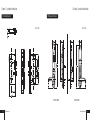
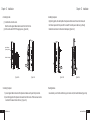
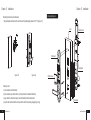
LIS2018-DT-1300
Residential RFID・Keypad Door Lock
USER MANUAL
MODEL:LIS2018-DT-1300
Residential RFID・Keypad Door Lock
Guangdong Level Intelligent Lock Industrial Co., Ltd.
ADD:No.I Pixi Industrial Park, Pingzhou, Foshan City, Guangdong Province, Zip:528000
TEL : +86-757-83998771
Email: [email protected]
WWW.LEVELLOCK.COM
catalogue
Chapter I
Chapter III
product introduction
01- 04
user guide
11 - 15
1.1 model and appearance
01
3.1 configure mother card
11
1.2 basic function
01
3.2 configure key card
12
1.3 parts and relative function
02
3.3 configure master key card
1.4 mortise dimension
03
3.4 configure passage mode card
12
13
1.5 panel dimension
04
3.5 delete a key card or multiple key cards
13
3.6 delete all sub-keycards
14
3.7 delete mother card
14
3.8 status of the cards
15
3.9 low voltage alarm
15
Chapter II
door lock installation
05 - 10
2.1 installation guide
05
2.2 installation requirement
05
2.3 installation steps
05
2.4 installation steps
06 - 09
2 .5 exploded view
10
Chapter IV
4 . 1 maintenance
16
Chapter I product introduction
Chapter I product introduction
1.1 model and appearance
1.3 model and appearance
back panel
product model
finishing
net weight
LIS2018-DT-1300
CR/PCR,PVD/SPVD.PVD/PCR
3.5kg
front panel
mortise
item
function
handles
detect the smart card
sensitive area
detect the smart card
face plate
lock with dead bolt
dead bolt
lock with dead bolt
keypad
operation and inputting code
1.2 basic function
1. perfect combination of mechanical and identification technology ;
2. unlocking methods :
(1). by RFID card;
(2). by code;
(3). by mechanical key;
3. mechanical dead bolt ;
4. sub-card and password can be added or deleted separately;
5. 4*1.5V LR6 alkaline batteries as power supply. The battery life can be up to 20000 times unlocking;
6. low voltage alarm:If the battery voltage becomes low, alarm will act and in this case the door can be
still opened for 50 times;
7. the passage mode can be set for meeting use by RFID card or code;
8. latch alarm:if the latch does not stretch completely, alarm will make in 3 seconds;
9. anti-latch-insert: to present the latch from unlocking illegally;
10. keypad: stainless steel is adopted, sealed by silica gel. It is water-resistant and anti-dust.
sensitive area
mortise
front panel
cylinder cover
dead bolt knob
dead bolt
front handle
back handle
anti-trust latch
latch
back panel
face plate
FRONT ELEVATION
01 www.levellock.com
battery case
keypad
SIDE ELEVATION
BACK ELEVATION
www.levellock.com
02
Chapter I product introduction
Chapter I product introduction
1.4 mortise dimension
1.5 lock panel dimension
unit: ( mm)
unit:( mm)
FRONT PANEL
03 www.levellock.com
BACK PANEL
www.levellock.com
04
Chapter II Installation
Chapter II Installation
2.1 precaution
2.4 installation step
1.drilling holes
The locks should be installed by installed by experienced specialists.
drilling the holes according to the installation drawings or hole-making templates to locate
the mortise and lock panels. The handle central line should be about 100cm from the
ground. (figure 2.4a)
2.2 installation requirement
(1). door:should be wooden door or anti-theft door. As for anti-theft
door. As for anti-theft door, the hole should be cut by door provider.
(2). door thickness:40-70mm .
(3). if there is decoration on the door, the width between the door's
edge and decoration should be at least 120mm.
unit:(mm)
mortise
template
frame
door
2.3 direction of lock
strike
plate
template
1000mm
base line
panel
template
A
inside
inside
inside
distance between the center
of handle and ground: 1000mm
outside
outside
left inside open
right inside open
A 2
inside
outside
left outside open
outside
hole-making drawing of door
three central lines
must be in one line
hole-making drawing of frame
right outside open
figure 2.4a
05 www.levellock.com
www.levellock.com
06
Chapter II Installation
Chapter II Installation
4. installing back panel
2.installing mortise
Align the big spindle, the small spindle of back panel and the relevant hole on the mortise, and
then fix back panel and front panel with 3 screws M5. note:the power cable must go through
the back hole and connect to the socket of back panel. (figure 2.4d)
(1) . install mortise in mortise room.
Note:the mortise signal cables must be lead out from the front hole.
(2) . fix the mortise with 2 ST4.8*19 tapping screws. (figure 2.4b)
signal cable must
go through this hole
this side for front panel
figure 2.4b
figure 2.4c
3.installing front panel
( 1).connect signal cable to the socket of front panel and make sure they are firmly connected.
(2). Insert the big spindle of front panel into relevant hole of the mortise. The three screw columns
must match the relevant hole on the door. (figure 2.4c)
07
www.levellock.com
figure 2.4d
figure 2.4e
5.loading batteries
remove battery cover from the small hole by a pin or relative tool, then load in batteries.(figure 2.4e)
www.levellock.com
08
Chapter II Installation
Chapter II Installation
2.5 exploded diagram
6.installing the strike box and strike plate
fixing strike plate and strike box into door frame with 2 peaked tapping screws ST 4.8*19 (figure 2.4f)
door
battery cover
front panel
back panel
figure 2.4f
figure 2.4g
cylinder cover
7. testing the lock
(1). turn handles to test its flexibility .
(2). turn handles to open test the latch, turn the knob to test the dead bolt's flexibility.
(3). open the door with mechanical key to test the flexibility of latch and dead bolt.
(4). test the anti-trust latch whether it can present the latch from unlocking illegally.(figure 2.4g)
09
www.levellock.com
face plate
www.levellock.com
10
Chapter III user guide
3.1 configure mother card
Unlocking method: RFID card or password.
A. card type: mother card, sub-card(including key card, master key card and passage mode card).
card's function: mother card: can unlock the door and dead bolt, and use for configure or
delete sub-card.
key card: can unlock the door but cannot unlock the dead bolt.
Chapter III user guide
3.2 configure key card
When the lock is in the stand-by status, swipe the mother card, and then 1 short "Di" is made.
Keep the mother card in the sensitive area till 3 short "Di Di Di" are made. At this moment, the
LED indicator flashes blue slowly, swipe the cards you need one by one until another short "Di"
is made. Now the key cards are successfully configured. Wait 5 seconds, the lock will turn to
stand-by mode.
master key card: can unlock the door and the dead bolt.
passage mode card: can unlock the door and dead bolt. When the lock is in the status of normal
close, it can turn the lock to normal open. When it is in the status of normal open, it can turn the
lock to normal close.
B.user guide for cards
(1)Insert and turn the mechanical key to make all the latches enter into the mortise. Keep holding
till you hear a short "Di" and see the indicator turns to red. At this moment put a legal card getting
close to sensitive area. Do not release the mechanical key until the sound "Di Di-" (1 short 1
long) makes. Now the mother card is successfully configured.
(2)Every lock can only configure one mother card. Configuration and deleting sub-cards require
the mother card. If the mother card is lost, please configure a mother card by above step.
(3)Every lock can configure at most 100 sub-cards. If the sound "Di Di Di Di Di"(5 short) makes, it
means the card's quota is full.
Note: some of the models use special button to configure the cards not by mechanical key.
11
www.levellock.com
3.3 configure master key card
When the lock is in the stand-by status, swipe the mother card, and then 1 short "Di" is made.
Swipe the mother card in the sensitive area for 2 times, and 2 times of 3 short "Di Di Di" are
made(Di Di Di...Di Di Di). At this moment,The LED indicator blue flashes faster, swipe the card
you need one by one until another short "Di" is made. Now the master key cards are
successfully configured. Wait 5 seconds, the lock will turn to stand-by mode.
www.levellock.com
12
Chapter III user guide
3.4 configure passage mode card
When the lock is in the stand-by status, swipe the mother card, and then 1 short "Di" made.
Swipe the mother card in the sensitive area for 1 times, and 3 times of 3 short "Di Di Di"
makes(Di Di Di...Di Di Di...Di Di Di). At this moment,The LED indicator flashes very rapidly.
Then swipe the cards you need one by one until another short "Di" makes. Now the passage
mode cards are successfully configured. Wait 5 seconds, the lock will turn to stand-by mode.
3.5 delete a key card or multiple key cards
When the lock is in the stand-by status, swipe the mother card, and then 1 short "Di" is made.
Swipe the mother card in the sensitive area for 1 time, and 1 times of 3 short "Di Di Di" is
made(Di Di Di). At this moment,the LED indicator flashes blue slowly. Wait some seconds, the
LED will flash red. Then swipe the cards you want to delete one by one until a short "Di" is made.
Now the sub-cards are successfully deleted. Wait 5 seconds, the lock will turn to stand-by
mode.
13
www.levellock.com
Chapter III user guide
3.6 delete all sub-key cards
When the lock is in the stand-by status, swipe the mother card, and then 1 short "Di" is made.
Swipe the mother card in the sensitive area for 1 time, and 1 times of 3 short "Di Di Di" is
made(Di Di Di). At this moment,the LED indicator flashes blue slowly. Wait some seconds, the
LED will flash red. Then swipe the mother cards you for 10 times, and 10 times of "Di Di Di" are
made. And then the LED will flash blue and red rapidly. Now all sub-cards are successfully
deleted. Wait 5 seconds, the lock will turn to stand-by mode.
3.7 delete mother card
Cut off the power(or remove one battery), insert the mechanical key, turn the mechanical key
clockwise and hold on. Then recover the power(load in batteries), release the mechanical key
until the LED indicator turns to red. And then turn the key clockwise for 4 times continuously in
5 seconds. After that, if a long "Di-Di" makes (1 long 1 short), it means the mother card is
deleted successfully.
www.levellock.com
14
Chapter III user guide
3.8 status of the cards
Chapter IV maintenance
4.1 maintenance
(1)Normal status of swiping cards
mother card: 1 short "Di".LED light up blue for 5 seconds.
key card and master key card: 1 short "Di". LED lights up blue for 1 second
passage mode card: 2 short "Di" (Di Di). LED lights up blue for 1 second.
After swiping cards, the lock will lock itself in 5 seconds.
(2)Abnormal status of swiping cards
When the door is locked by dead bolt, if you use normal key cards to unlock the door, 1 "Di"
will make and LED flashes blue and red for 1 second. If illegal cards are used, the LED will
flash blue and red for 1 second and no sound will make.
Do not get contact with
corrosive substance in case
of damaging the protection
layer of locks.
Do not hang stuffs on the
handle in case of damaging
its flexibility.
If the door deforms and the
latch cannot go into the
strike box smoothly, you
have to adjust the position
of the strike plate.
If the low voltage alarm
makes, please change the
all batteries simultaneously.
Pay attention to the
direction of negative and
positive pole.
Keep the mechanical key in
safe place.
3 . 9 low voltage alarm
If there are 3 short "Di Di Di" make and the LED light up red when the lock is unlocked. That
means the batteries voltage is too low, you have to change the batteries as soon as possible. In
the low voltage situation, the door can be unlocked for 50 times.
From the 51th time, the lock will be self-locked. You can use the following way to unlock the door:
A. Swipe the legal cards contentiously for 3 times.
B. Use the mechanical
C. Use the outer power supply(DC6V) to power the door, and then unlock the door.
15
www.levellock.com
www.levellock.com
16