1
ProNet Series AC Servo User's Manual
(Version:V2.17)
Copyright © 2011 ESTUN AUTOMATION TECHNOLOGY CO., LTD
All rights reserved. No part of this publication may be reproduced, stored in a retrieval system, or transmitted, in any form, or
by any means, mechanical, electronic, photocopying, recording, or otherwise, without the prior written permission of ESTUN.
No patent liability is assumed with respect to the use of the information contained herein.
ProNet Series AC Servo User's Manual
About this manual
This manual describes the following information required for designing and maintaining ProNet series servo drives.
•Specification of the servo drives and servomotors.
•Procedures for installing the servo drives and servomotors.
•Procedures for wiring the servo drives and servomotors.
•Procedures for operating of the servo drives.
•Procedures for using the panel operator.
•Communication protocols.
•Ratings and characteristics.
Intended Audience:
•Those designing ProNet series servo drive systems.
•Those installing or wiring ProNet series servo drives.
•Those performing trial operation or adjustments of ProNet series servo drives.
•Those maintaining or inspecting ProNet series servo drives.
-1-
ProNet Series AC Servo User's Manual
Safety Precautions
■ Do not connect the servomotor directly to the local electrical network.
Failure to observe this may result in damage to servomotor.
■ Do not plug or unplug connectors from servo drive when power is on.
Failure to observe this may result in damage to servo drive and servomotor.
■Please note that even after power is removed, residual voltage still remains in the capacitor inside the servo drive. If
inspection is to be performed after power is removed, please wait 5 minutes to avoid risk of electrical shock.
■ Keep servo drives and other devices separated by at least 10mm.
The servo drive generates heat. Install the servo drive so that it can radiate heat freely. When installing servo drives
with other devices in a control panel, provide at least 10mm space between them and 50mm space above and below
them. Please install servo drives in an environment free from condensation, vibration and shock.
■ Perform noise reduction and grounding properly.
Please comply with the following instructions to avoid noise generated by signal lines.
1. Separate high-voltage cables from low-voltage cables.
2. Use cables as short as possible.
3. Single point grounding is required for the servomotor and servo drive (grounding resistance 100Ω or below).
4. Never use a line filter for the power supply in the circuit.
■ Conduct a voltage resistance test for the servo drive under the following conditions:
1. Input voltage: AC 1500Vrms, 1 minute
2. Braking current: 100mA
3. Frequency:50/60Hz
4. Voltage applied point: Between L1, L2,L3 terminals and frame ground.
■ Use a fast-response type ground-fault interrupter.
For a ground-fault interrupter, always use a fast-response type or one designed for PWM inverters. Do not use a
time-delay type.
■ Do not make any extreme adjustments or setting changes of parameters.
Failure to observe this caution may result in injury or damage to the product due to unstable operation.
■ The servomotor cannot be operated by turning the power on and off.
Frequently turning the power ON and OFF causes the internal circuit elements to deteriorate, resulting in unexpected
problems. Always start or stop the servomotor by using reference pulses.
■ Follow the instructions for PCB use:
1. Before touch the PCB, the body of the user must be discharged.
2. The PCB cannot be contact with highly insulating materials
3. The PCB is only allowed to put on the conductive pad.
4. The PCB is only allowed to store and transport packaging in conductive wrapper or conductive foam rubber or
aluminum foil.
■ Precautions on turning ON and turning OFF the servo drive:
1. When turning on the servo drive, make sure that the control power supply has be turned on before turning on the
main circuit power supply.
2. When turning off the servo drive, make sure that the main circuit power supply has be turned off before turning off the
control power supply.
-2-
ProNet Series AC Servo User's Manual
—Contents—
About this manual ........................................................................................................................................................... - 1 Safety Precautions .......................................................................................................................................................... - 2 Chapter 1 ........................................................................................................................................................................ - 7 Checking Products and Parts Names.............................................................................................................................. - 7 1.1 Checking Products on Delivery ......................................................................................................................... - 7 1.1.1 Servomotor ............................................................................................................................................ - 7 1.1.2 Servo drive .......................................................................................................................................... - 10 1.2 Part Names ..................................................................................................................................................... - 17 1.2.1 Servomotor .......................................................................................................................................... - 17 1.2.2 Servo drive .......................................................................................................................................... - 17 Chapter 2 ...................................................................................................................................................................... - 23 Installation ..................................................................................................................................................................... - 23 2.1 Servomotor ..................................................................................................................................................... - 23 2.1.1 Storage ................................................................................................................................................ - 23 2.1.2 Installation Sites .................................................................................................................................. - 23 2.1.3 Installation Alignment ........................................................................................................................... - 24 2.1.4 Installation Orientation ......................................................................................................................... - 24 2.1.5 Handling Oil and Water........................................................................................................................ - 24 2.1.6 Cable Tension ...................................................................................................................................... - 25 2.1.7 Install to the Client ............................................................................................................................... - 25 2.2 Servo Drive ..................................................................................................................................................... - 25 2.2.1 Storage ................................................................................................................................................ - 25 2.2.2 Installation Sites .................................................................................................................................. - 25 2.2.3 Installation Orientation ......................................................................................................................... - 26 2.2.4 Installation Method............................................................................................................................... - 26 Chapter 3 ...................................................................................................................................................................... - 28 Wiring ............................................................................................................................................................................ - 28 3.1 Main Circuit Wiring .......................................................................................................................................... - 28 3.1.1 Names and Functions of Main Circuit Terminals .................................................................................. - 28 3.1.2 Typical Main Circuit Wiring Examples .................................................................................................. - 29 3.2 I/O Signals ...................................................................................................................................................... - 33 3.2.1 Examples of I/O Signal Connections ................................................................................................... - 33 3.2.2 I/O Signal Names and Functions ......................................................................................................... - 34 3.2.3 I/O Signal Connector (CN1) Terminal Layout ...................................................................................... - 36 3.2.4 Interface Circuit ................................................................................................................................... - 37 3.3 Wiring Encoders.............................................................................................................................................. - 38 3.3.1 Connecting an Encoder(CN2).............................................................................................................. - 38 3.3.2 Encoder Connector(CN2) Terminal Layout.......................................................................................... - 40 3.4 Communication Connection ............................................................................................................................ - 40 3.4.1 Communication Connector(CN3) Terminal Layout .............................................................................. - 40 3.4.2 Communication Connector(CN4) Terminal Layout .............................................................................. - 41 3.5 Standard Wiring Examples .............................................................................................................................. - 42 -
-3-
ProNet Series AC Servo User's Manual
3.5.1 Single-phase 200V ProNet-A5A~04A/ProNet-E-A5A~04A ............................................................... - 42 3.5.2 Three-phase 200V ProNet-08A~50A/ProNet-E-08A~50A ................................................................ - 43 3.5.3 Three-phase 400V ProNet-10D~70D/ProNet-E-10D~50D ............................................................... - 44 3.5.4 Three-phase 400V ProNet-75D~2BD ................................................................................................ - 45 3.5.5 Single-phase 100V ProNet-02B/ProNet-E-02B ................................................................................... - 46 3.5.6 Single-phase 100V ProNet-04B /ProNet-E-04B .................................................................................. - 47 3.5.7 Single-phase 100V ProNet-08B/ ProNet-E-08B .................................................................................. - 48 3.5.8 Position Control Mode ......................................................................................................................... - 49 3.5.9 Speed Control Mode ............................................................................................................................ - 50 3.5.10 Torque Control Mode ......................................................................................................................... - 51 3.6 Wiring for Noise Control .................................................................................................................................. - 52 3.6.1 Noise Control ....................................................................................................................................... - 52 3.6.2 Precautions on Connecting Noise Filter .............................................................................................. - 53 3.7 Installation Conditions of EMC Directives ....................................................................................................... - 55 3.8 Using More than One Servo Drive .................................................................................................................. - 57 3.9 Connecting DC Bus ........................................................................................................................................ - 59 Chapter 4 ...................................................................................................................................................................... - 60 Operation ...................................................................................................................................................................... - 60 4.1 Trial Operation ................................................................................................................................................ - 60 4.1.1 Trial Operation for Servomotor Without Load ...................................................................................... - 62 4.1.2 Trial Operation for Servomotor without Load from Host Reference ..................................................... - 64 4.1.3 Trial Operation with the Servomotor Connected to the Machine.......................................................... - 68 4.1.4 Trial Operation for Servomotor with Brakes ......................................................................................... - 69 4.1.5 Position Control by Host Controller...................................................................................................... - 69 4.2 Control Mode Selection................................................................................................................................... - 70 4.3 Setting Common Basic Functions ................................................................................................................... - 71 4.3.1 Setting the Servo ON Signal ................................................................................................................ - 71 4.3.2 Switching the Servomotor Rotation Direction ...................................................................................... - 72 4.3.3 Setting the Overtravel Limit Function ................................................................................................... - 73 4.3.4 Setting for Holding Brakes ................................................................................................................... - 76 4.3.5 Instantaneous Power Loss Settings..................................................................................................... - 79 4.4 Absolute Encoders .......................................................................................................................................... - 80 4.4.1 Selecting an Absolute Encoder ............................................................................................................ - 80 4.4.2 Handling Battery .................................................................................................................................. - 81 4.4.3 Replacing Battery ................................................................................................................................ - 82 4.4.4 Absolute Encoder Setup(Fn010、Fn011) ............................................................................................ - 82 4.5 Operating Using Speed Control with Analog Reference.................................................................................. - 83 4.5.1 Setting Parameters .............................................................................................................................. - 83 4.5.2 Setting Input Signals ............................................................................................................................ - 84 4.5.3 Adjusting Reference Offset .................................................................................................................. - 85 4.5.4 Soft Start .............................................................................................................................................. - 88 4.5.5 Speed Reference Filter Time Constant ................................................................................................ - 88 4.5.6 S-curve Risetime ................................................................................................................................. - 89 4.5.7 Using the Zero Clamp Function ........................................................................................................... - 89 4.5.8 Encoder Signal Output......................................................................................................................... - 91 4.5.9 Speed coincidence output ................................................................................................................... - 92 -
-4-
ProNet Series AC Servo User's Manual
4.6 Operating Using Position Control .................................................................................................................... - 93 4.6.1 Basic Setting in Position Control.......................................................................................................... - 93 4.6.2 Setting the Clear Signal ....................................................................................................................... - 97 4.6.3 Setting the Electronic Gear .................................................................................................................. - 97 4.6.4 Smoothing ......................................................................................................................................... - 100 4.6.5 Low Frequency Vibration Suppression .............................................................................................. - 101 4.6.6 Positioning Completion Output Signal ............................................................................................... - 103 4.6.7 Reference Pulse Inhibit Function (INHIBIT) ....................................................................................... - 104 4.6.8 Position Control (contact reference).................................................................................................. - 105 4.6.9 Position Homing Control (Homing Function)...................................................................................... - 108 4.7 Operating Using Torque Control.................................................................................................................... - 111 4.7.1 Setting Parameters ............................................................................................................................ - 111 4.7.2 Torque Reference Input ..................................................................................................................... - 112 4.7.3 Adjusting the Reference Offset .......................................................................................................... - 113 4.7.4 Limiting Servomotor Speed During Torque Control............................................................................ - 114 4.8 Operating Using Speed Control with an Internally Set Speed ....................................................................... - 115 4.8.1 Setting Parameters ............................................................................................................................ - 116 4.8.2 Input Signal Settings .......................................................................................................................... - 117 4.8.3 Operating Using an Internally Set Speed ........................................................................................... - 117 4.9 Limiting Torque.............................................................................................................................................. - 118 4.9.1 Internal Torque Limit .......................................................................................................................... - 118 4.9.2 External Torque Limit ......................................................................................................................... - 119 4.9.3 Torque Limiting Using an Analog Voltage Reference ........................................................................ - 120 4.10 Control Mode Selection ............................................................................................................................... - 121 4.10.1 Setting Parameters .......................................................................................................................... - 121 4.10.2 Switching the Control Mode ............................................................................................................. - 121 4.11 Other Output Signals ................................................................................................................................... - 122 4.11.1 Servo alarm output........................................................................................................................... - 122 4.11.2 Rotation Detection Output Signal (/TGON) ...................................................................................... - 123 4.11.3 Servo Ready (/S-RDY) Output ......................................................................................................... - 123 4.11.4 Encoder C Pluse Output (/PGC) ...................................................................................................... - 123 4.11.5 Over travel signal output (OT) .......................................................................................................... - 124 4.11.6 Servo Enabled Motor Excitation Output(/RD)................................................................................... - 124 4.11.7 Torque Limit Detection Output (/CLT) ............................................................................................... - 124 4.11.8 Torque Detection Output (/TCR) ...................................................................................................... - 126 4.12 Online Autotuning........................................................................................................................................ - 126 4.12.1 Online Autotuning ............................................................................................................................ - 126 4.12.2 Online Autotuning Procedure ........................................................................................................... - 127 4.12.3 Setting Online Autotuning ................................................................................................................ - 128 4.12.4 Machine Rigidity Setting for Online Autotuning ................................................................................ - 128 4.13 Inertia ......................................................................................................................................................... - 130 4.14 Adaptive notch filter..................................................................................................................................... - 130 4.14.1 Adaptive notch filter principle ........................................................................................................... - 130 4.14.2 Related Parameters ......................................................................................................................... - 131 4.15 The use of Torque Observer ....................................................................................................................... - 131 4.15.1 Equivalent load inertia ratio is adaptive ........................................................................................... - 131 -
-5-
ProNet Series AC Servo User's Manual
4.15.2 Load torque compensation .............................................................................................................. - 132 4.15.3 Related parameters ......................................................................................................................... - 132 Chapter 5 .................................................................................................................................................................... - 134 Panel Operator ............................................................................................................................................................ - 134 5.1 Basic Operation ............................................................................................................................................ - 134 5.1.1 Functions on Panel Operator ............................................................................................................. - 134 5.1.2 Resetting Servo Alarms ..................................................................................................................... - 134 5.1.3 Basic Mode Selection ........................................................................................................................ - 135 5.1.4 Status Display Mode .......................................................................................................................... - 135 5.1.5 Operation in Parameter Setting Mode ............................................................................................... - 137 5.1.6 Operation in Monitor Mode ................................................................................................................ - 138 5.2 Operation in Utility Function Mode ................................................................................................................ - 141 5.2.1 Alarm Traceback Data Display........................................................................................................... - 141 5.2.2 Parameter Settings Initialization ........................................................................................................ - 142 5.2.3 Operation in JOG Mode ..................................................................................................................... - 143 5.2.4 Automatic Adjustment of the Speed Reference Offset ....................................................................... - 144 5.2.5 Manual Adjustment of the Speed Reference Offset ........................................................................... - 145 5.2.6 Offset-adjustment of Servomotor Current Detection Signal ............................................................... - 146 5.2.7 Software Version Display ................................................................................................................... - 148 5.2.8 Position Teaching Function ................................................................................................................ - 148 5.2.9 Static Inertia Detection ....................................................................................................................... - 148 5.2.10 Absolute Encoder Multiturn Data and Alarm Reset .......................................................................... - 149 5.2.11 Absolute Encoder Related Alarms Reset ......................................................................................... - 149 Chapter 6 .................................................................................................................................................................... - 150 MODBUS Communication........................................................................................................................................... - 150 6.1 RS-485 Communication Wiring ..................................................................................................................... - 150 6.2 MODBUS Communication Related Parameters............................................................................................ - 151 6.3 MODBUS Communication Protocol .............................................................................................................. - 152 6.3.1 Code Meaning ................................................................................................................................... - 152 6.3.2 Communication Error Disposal .......................................................................................................... - 158 6.3.3 Data Communication Address of Servo State .................................................................................... - 159 Chapter 7 .................................................................................................................................................................... - 162 Specifications and Characters ..................................................................................................................................... - 162 7.1 Servo drive Specifications and Models ......................................................................................................... - 162 7.2 Servo drive Dimensional Drawings ............................................................................................................... - 165 Appendix A .................................................................................................................................................................. - 168 Parameter ................................................................................................................................................................... - 168 A.1 Parameter List .............................................................................................................................................. - 168 A.2 Description of Parameter Type ..................................................................................................................... - 175 A.3 Parameters in detail ...................................................................................................................................... - 176 Appendix B .................................................................................................................................................................. - 196 Alarm Display .............................................................................................................................................................. - 196 -
-6-
ProNet Series AC Servo User's Manual
Chapter 1
Checking Products and Parts Names
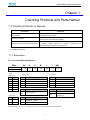
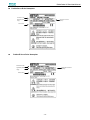
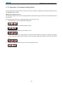
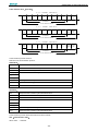
1.1 Checking Products on Delivery
Check Items
Comments
Are the delivered products the ones that
Check the model numbers marked on the nameplate on the
were ordered?
servomotor and servo drive.
Check the overall appearance, and check for damage or scratches
Is there any damage?
that may have occurred during shipping.
If the servomotor shaft can be easily rotated by hand, then the motor
Does the servomotor shaft rotate smoothly?
is working normally. However, if a brake is installed on the
servomotor, then it cannot be turned by hand.
If any of the above items are faulty or incorrect, contact your ESTUN representative or the dealer from whom you
purchased the products.
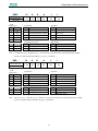
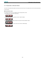
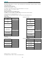
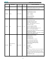
1.1.1 Servomotor
Servomotor Model Designation
EMJ–
ESTUN Servomotor
08
A
P
B
【1+2】
【3】
【4】
【5】
1
1
【6】
【7】
-WR
【8+9】
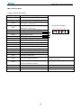
EMJ Model
【1+2】
Rated Output
【4】Encoder
【7】Option
Code
Spec.
Code
Spec.
Code
Spec.
A5
0.05 kW
D
Incremental encoder :131072P/R
1
None
01
0.1 kW
P
Incremental Wire-saving Type:2500P/R
2
With oil seal
02
0.2kW
F
Incremental encoder :1048576P/R
3
With brake (DC24V)
04
0.4kW
S
Absolute encoder:131072P/R
4
With oil seal and brake(DC24V)
08
0.75kW
【5】Designing Sequence
【8+9】Connector
10
1.0kW
Code
Code
A,B,
C,H
Spec.
Spec.
Standard connector
Designing sequence
【3】Voltage
【6】Shaft End
Code
Spec.
Code
Spec.
A
200VAC
1
Straigt without key (Standard)
B
100VAC
2
Straigt with key and tap
WR
Water proof connector (Incremental
Wire-saving Type )
Note:EMJ-A5/01□□□□□□ and EMJ-□□□D/F/S□□ support water proof connector default.
-7-
ProNet Series AC Servo User's Manual
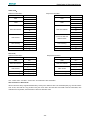
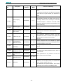
EMG–
ESTUN Servomotor
10
A
【1+2】
【3】
D
【4】
A
【5】
1
【6】
1
【7】
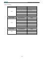
EMG Model
【1+2】
Rated Output
Code
Spec.
【4】Encoder
【7】Option
Code
Spec.
Code
Spec.
Incremental encoder :131072P/R
1
None
10
1.0kW
D
15
1.5kW
P
Incremental Wire-saving Type:2500P/R
2
With oil seal
20
2.0kW
F
Incremental encoder :1048576P/R
3
With brake (DC24V)
30
3.0kW
S
Absolute encoder:131072P/R
4
With oil seal and brake(DC24V)
50
5.0kW
【3】Voltage
【5】Designing Sequence
【6】Shaft End
Code
Code
Spec.
Code
Spec.
Spec.
A
200VAC
A
Designing sequence A
1
Straigt without key (Standard)
D
400VAC
B
Designing sequence B
2
Straigt with key and tap
Note:1. The EMG-30A□A□□, EMG-50A□A□□ servomotors are not mounted with an incremental encoder 131072P/R.
2. There is no brake mounted on the EMG-□□□D□□□ servomotor.
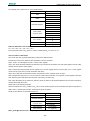
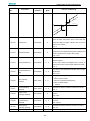
EML–
ESTUN Servomotor
10
A
【1+2】
【3】
D
【4】
A
1
【5】
【6】
1
【7】
EML Model
【1+2】
【4】Encoder
【7】Option
Code
Spec.
Code
1.0kW
D
Incremental encoder :131072P/R
1
None
20
2.0kW
P
Incremental Wire-saving Type:2500P/R
2
With oil seal
30
3.0kW
S
Absolute encoder:131072P/R
3
With brake (DC24V)
4.0kW
F
Incremental encoder :1048576P/R
4
With oil seal and brake(DC24V)
Rated Output
Code
10
40
Spec.
Spec.
【3】Voltage
【5】Designing Sequence
【6】Shaft End
Code
Code
Spec.
Code
Spec.
Spec.
A
200VAC
A
Designing sequence A
1
Straigt without key (Standard)
D
400VAC
B
Designing sequence B
2
Straigt with key and tap
Note:1. EML-20□□A□□、EML-30□□A□□、EML-40□□A□□are not mounted with an incremental encoder 131072P/R.
2. There is no brake mounted on the EML-10□D□□□ servomotor.
-8-
ProNet Series AC Servo User's Manual
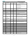
EMB–
ESTUN Servomotor
1E
D
S
【1+2】
【3】
【4】
A
【5】
1
【6】
1
【7】
EMB Model
【1+2】
Rated Output
Code
Spec.
【4】Encoder
【7】Option
Code
Spec.
Code
Spec.
Absolute encoder:131072P/R
1
None
Resolver
75
7.5kW
S
1A
11.0kW
R
1E
15.0kW
2B
22.0kW
2
With oil seal
3
With brake (DC24V)
4
With oil seal and brake(DC24V)
【3】Voltage
【5】Designing Sequence
【6】Shaft End
Code
Spec.
Code
Spec.
Code
Spec.
D
400VAC
A
Designing sequence A
1
Straigt without key (Standard)
2
Straigt with key and tap
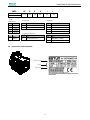
Appearance and Nameplate
Servomotor model
Ratings
{
Serial number
-9-
ProNet Series AC Servo User's Manual
1.1.2 Servo drive
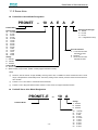
ProNet Servo drive Model Designation
PRONET
–
10
A
E
A
-P
ProNet Model
Extended module type
-D DP100
-E EC100
-P PL100
-EC integrated EC100②
Rated Output
A5
0.05 kW
01
0.1 kW
02
0.2 kW
04
0.4 kW
08
0.75 kW
10
1.0 kW
15
1.5 kW
20
2.0 kW
30
3.0 kW
50
5.0 kW
70
7.0kW
75
7.5 kW
1A 11 kW
1E
15 kW
2B
22 kW
Encoder Interface
A 17-bit serial encoder
Absolute Encoder
1
B Resolver○
F 20-bit serial encoder
Absolute Encoder
Voltage
A 200VAC
B:100VAC
D 400VAC
Control Mode
M Speed control, torque control, position control
E Speed control, torque control, position control (support extended module)
Note:
① Resolver, with the feature of high reliability and long service life, is suitable for harsh environments and a wide
range of temperatures and humidity levels. The factory setting for the resolver precision used in the ESTUN servo
drive is 4096.
②
ProNet-□□□□□-EC refers to《EtherCAT User's Manual》
。
③
ProNet-□□□E□ Supports AE100 model. ProNet-□□□M□ does not support extended module.
ProNet-E Servo drive Model Designation
PRONET–E
ProNet-E Model
- 10 -
–
10
A
Voltage
A:200VAC
B:100VAC
D:400VAC
Rated Output
A5
0.05 kW
01
0.1 kW
02
0.2kW
04
0.4 kW
08
0.75 kW
10
1.0 kW
15
1.5 kW
20
2.0 kW
30
3.0 kW
50
5.0 kW
ProNet Series AC Servo User's Manual
Note:
1 ProNet-E is only available with the wire-saving incremental encoder (2500 P/R)
○
○
2 ProNet-E does not support extended module.
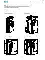
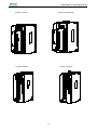
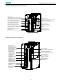
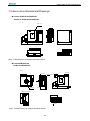
ProNet Servo Drive Appearance
ProNet- A5A/01A/02A/04A
ProNet-08A/10A
CHARGE
CN3
POWER
L1
CN4
L2
L3
+1
+2
L2C
B1
CN1
-
L1C
B2
B3
U
CN2
V
W
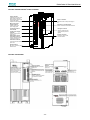
ProNet-15A/20A
CHARGE
POWER
CN3
CN3
POWER
L1
L2
L2
L3
CN4
L1
L3
+1
+1
+2
+2
CN4
CHARGE
ProNet-10D/15D/20D
-
-
GND
B1
B2
B2
B3
B3
U
U
V
V
W
CN2
B1
W
- 11 -
CN2
CN1
L2C
24V
CN1
L1C
ProNet Series AC Servo User's Manual
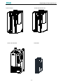
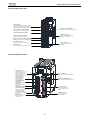
ProNet-30A/50A
ProNet-30D/50D/70D/75D
CHARGE
CN3
L1
L1
L2
CN4
L3
L3
CN1
+2
+2
CN1
+1
+1
-
-
24V
GND
L2C
B1
B1
B2
CN2
L1C
B2
B3
B3
U
U
V
V
W
CN2
L2
POWER
CN3
POWER
CN4
CHARGE
W
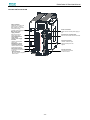
ProNet-1AD/1ED/2BD
ProNet-02B
- 12 -
ProNet Series AC Servo User's Manual
ProNet-04B
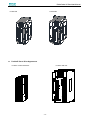
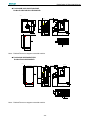
ProNet-E Servo Drive Appearance
ProNet-E- A5A/01A/02A/04A
ProNet-E-08A/10A
POWER
CN3
CHARGE
L1
+2
CN4
CN3
L3
CN4
L2
CHARGE
+1
L1
L2
FG
-
L1C
+2
L2C
B1
L1C
CN1
-
CN1
+1
B2
B3
L2C
B1
U
B2
B3
V
V
W
U
- 13 -
CN2
W
CN2
ProNet-08B
ProNet Series AC Servo User's Manual
ProNet-E-15A/20A
ProNet-E-10D/15D/20D
CHARGE
CN3
POWER
CHARGE
POWER
CN3
L1
L3
+1
CN4
L2
L3
CN4
L2
L1
+2
+1
-
+2
GND
L1C
B1
CN1
L2C
CN1
24V
-
B2
B1
B3
B2
U
B3
W
ProNet-E-30A/50A
CHARGE
ProNet-E-30D/50D
CHARGE
L2
L3
L3
+1
+2
-
-
L1C
24V
L2C
GND
CN2
B1
CN1
+1
CN1
+2
CN4
L1
CN4
L2
POWER
CN3
CN3
POWER
L1
B1
B2
B2
B3
B3
U
U
V
V
W
W
- 14 -
CN2
W
CN2
V
CN2
V
U
ProNet Series AC Servo User's Manual
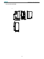
ProNet-E-02B
ProNet-E-04B
ProNet-E-08B
- 15 -
ProNet Series AC Servo User's Manual
ProNet Servo Drive Nameplate
Servodrive model
Applicable power
supply
Applicable servomotor
capacity
Serial number
ProNet-E Servo Drive Nameplate
Servodrive model
Applicable servomotor
capacity
Applicable power
supply
Serial number
- 16 -
ProNet Series AC Servo User's Manual
1.2 Part Names
1.2.1 Servomotor
Servomotor without gear and brake.
Encoder
Mounting hole
Shell
Output shaft
Flange
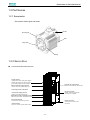
1.2.2 Servo drive
ProNet-02A/04A/ProNet-E-02A/04A
Charge indicator
Lights when the main circuit power supply is
ON and stays lit as long as the main circuit
power supply capacitor remains charged.
Connector for communication
Used to communicate with other devices.
Main circuit power supply terminals
Used for main circuit power supply input.
Connecting terminal of DC reactor
I/O signal connector
Used for reference input signals
and sequence I/O signals.
Control power supply terminals
Used for control power supply input.
Regenerative resistor connecting terminals
Used to connect external regenerative resistors.
Servomotor terminals
Connects to the servomotor power line.
Encoder connector
Connects to the encoder in the
servomotor.
Ground terminal
Be sure to connect to protect electric shock.
- 17 -
ProNet Series AC Servo User's Manual
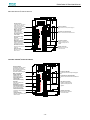
ProNet-08A/10A /ProNet-E-08A/10A
CN3
POWER
Power on indicator
Lights when the control power supply is
on.
L1
L2
Connector for communication
Used to communicate with other devices.
CN4
L3
+1
+2
-
L1C
CN1
Control power supply
terminals
Used for control power
supply input.
Regenerative resistor
connecting terminals
Used to connect external
regenerative resistors.
Servomotor terminals
Connects to the servomotor
power line.
Ground terminal
Be sure to connect to protect
electric shock.
CHARGE
L2C
B1
I/O signal connector
Used for reference input
signals and sequence I/O
signals.
B2
B3
U
V
CN2
Charge indicator
Lights when the main circuit
power supply is ON and
stays lit as long as the main
circuit power supply
capacitor remains charged.
Main circuit power
supply terminals
Used for main circuit
power supply input.
Connecting terminal
of DC reactor
W
Encoder connector
Connects to the encoder
in the servomotor.
CN3
Power on indicator
Lights when the control power supply is
on.
Connector for communication
Used to communicate with other devices.
CHARGE
POWER
L1
L2
L3
+1
+2
-
I/O signal connector
Used for reference input
signals and sequence I/O
signals.
L2C
CN1
L1C
B1
B2
B3
U
V
W
Encoder connector
Connects to the encoder
in the servomotor.
CN2
Charge indicator
Lights when the main circuit
power supply is ON and
stays lit as long as the main
circuit power supply
capacitor remains charged.
Main circuit power
supply terminals
Used for main circuit
power supply input.
Connecting terminal
of DC reactor
Control power supply
terminals
Used for control power
supply input.
Regenerative resistor
connecting terminals
Used to connect external
regenerative resistors.
Servomotor terminals
Connects to the servomotor
power line.
Ground terminal
Be sure to connect to protect
electric shock.
CN4
ProNet-15A/20A/ ProNet-E-15A/20A
- 18 -
ProNet Series AC Servo User's Manual
ProNet-10D/15D/20D/ProNet-E-10D/15D/20D
Charge indicator
Lights when the main circuit power supply is
ON and stays lit as long as the main circuit
power supply capacitor remains charged.
CHARGE
CN3
POWER
L1
Main circuit power supply terminals
Used for main circuit power supply input.
CN4
L2
L3
+1
Connecting terminal of DC reactor
Power on indicator
Lights when the control power supply is on.
Connector for communication
Used to communicate with other devices.
+2
24V
GND
CN1
-
Control power supply terminals
Used for control power supply input.
Regenerative resistor connecting terminals
Used to connect external regenerative resistors.
B1
B2
B3
Servomotor terminals
Connects to the servomotor power line.
Ground terminal
Be sure to connect to protect electric shock.
I/O signal connector
Used for reference input
signals and sequence I/O
signals.
U
CN2
V
W
Encoder connector
Connects to the encoder
in the servomotor.
ProNet-30A/50A/ ProNet-E-30A/50A
Charge indicator
Lights when the main circuit
power supply is ON and
stays lit as long as the main
circuit power supply
capacitor remains charged.
Control power supply
terminals
Used for control power
supply input.
Regenerative resistor
connecting terminals
Used to connect external
regenerative resistors.
CN3
L2
CN4
L1
+1
+2
I/O signal connector
Used for reference input
signals and sequence I/O
signals.
-
L1C
L2C
B1
Encoder connector
Connects to the encoder
in the servomotor.
B2
B3
U
V
Servomotor terminals
Connects to the servomotor
power line.
Power on indicator
Lights when the control power supply is
on.
Connector for communication
Used to communicate with other devices.
L3
CN1
Connecting terminal
of DC reactor
POWER
CN2
Main circuit power
supply terminals
Used for main circuit
power supply input.
CHARGE
W
Ground terminal
Be sure to connect to protect
electric shock.
- 19 -
ProNet Series AC Servo User's Manual
ProNet-30D/50D/70D/75D/ ProNet-E-30D/50D
Charge indicator
Lights when the main circuit
power supply is ON and
stays lit as long as the main
circuit power supply
capacitor remains charged.
Control power supply
terminals
Used for control power
supply input.
Regenerative resistor
connecting terminals
Used to connect external
regenerative resistors.
Servomotor terminals
Connects to the servomotor
power line.
Power on indicator
Lights when the control power supply is
on.
CN3
POWER
Connector for communication
Used to communicate with other devices.
L2
CN4
L1
L3
+1
I/O signal connector
Used for reference input
signals and sequence I/O
signals.
CN1
+2
-
24V
GND
B1
Encoder connector
Connects to the encoder
in the servomotor.
CN2
Main circuit power
supply terminals
Used for main circuit
power supply input.
Connecting terminal
of DC reactor
CHARGE
B2
B3
U
V
W
Ground terminal
Be sure to connect to protect
electric shock.
ProNet-1AD/1ED/2BD
- 20 -
ProNet Series AC Servo User's Manual
ProNet-02B/ProNet-E-02B
Charge indicator
Lights when the main circuit power supply is
ON and stays lit as long as the main circuit
power supply capacitor remains charged.
Connector for communication
Used to communicate with other devices.
Main circuit power supply terminals
Used for main circuit power supply input.
Connecting terminal of DC reactor
I/O signal connector
Used for reference input signals
and sequence I/O signals.
Control power supply terminals
Used for control power supply input.
Regenerative resistor connecting terminals
Used to connect external regenerative resistors.
Servomotor terminals
Connects to the servomotor power line.
Encoder connector
Connects to the encoder in the
servomotor.
Ground terminal
Be sure to connect to protect electric shock.
ProNet-04B/ProNet-E-04B
Charge indicator
Lights when the main circuit
power supply is ON and
stays lit as long as the main
circuit power supply
capacitor remains charged.
Main circuit power
supply terminals
Used for main circuit
power supply input.
Connecting terminal
of DC reactor
Power on indicator
Lights when the control power supply is
on.
Connector for communication
Used to communicate with other devices.
Control power supply
terminals
Used for control power
supply input.
Regenerative resistor
connecting terminals
Used to connect external
regenerative resistors.
Servomotor terminals
Connects to the servomotor
power line.
Ground terminal
Be sure to connect to protect
electric shock.
I/O signal connector
Used for reference input
signals and sequence I/O
signals.
Encoder connector
Connects to the encoder
in the servomotor.
- 21 -
ProNet Series AC Servo User's Manual
ProNet-08B /ProNet-E-08B
Charge indicator
Lights when the main circuit
power supply is ON and
stays lit as long as the main
circuit power supply
capacitor remains charged.
Main circuit power
supply terminals
Used for main circuit
power supply input.
Connecting terminal
of DC reactor
Control power supply
terminals
Used for control power
supply input.
Regenerative resistor
connecting terminals
Used to connect external
regenerative resistors.
Servomotor terminals
Connects to the servomotor
power line.
Ground terminal
Be sure to connect to protect
electric shock.
Power on indicator
Lights when the control power supply is
on.
Connector for communication
Used to communicate with other devices.
I/O signal connector
Used for reference input
signals and sequence I/O
signals.
Encoder connector
Connects to the encoder
in the servomotor.
- 22 -
ProNet Series AC Servo User's Manual
Chapter 2
Installation
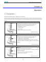
2.1 Servomotor
Servomotor can be installed either horizontally or vertically. However, if the servomotor is installed incorrectly, the
service life of the servomotor will be shortened or unexpected problems may occur.
Please observe the installation instructions described below to install the servomotor correctly.
Before installation:
Anticorrosive paint is coated on the edge of the servomotor shaft. Clean off the anticorrosive paint thoroughly using
a cloth moistened with thinner.
Avoid getting thinner on other parts of the servomotor when cleaning the shaft.
Anticorrosive paint
2.1.1 Storage
When the servomotor is not being used, store it in an area with a temperature between -25℃ and 60℃ with the power
cable disconnected.
2.1.2 Installation Sites
The servomotor is designed for indoor use. Install the servomotor in an environment which meets the following
conditions.
Free from corrosive and explosive gases.
Well-ventilated and free from dust and moisture.
Ambient temperature from 0 to 40℃.
Relative humidity from 26% to 80%( non-condensing).
Facilitates inspection and cleaning.
- 23 -
ProNet Series AC Servo User's Manual
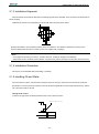
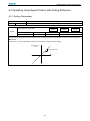
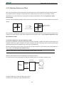
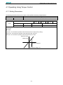
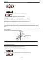
2.1.3 Installation Alignment
Align the shaft of the servomotor with that of the machinery shaft to be controlled. Then connect the two shafts with an
elastic coupling.
Install the servomotor so that alignment accurancy falls within the range shown below.
Measure this distance at four different positions in the circumference. The difference between the maximum and
minimum measurements must be 0.03mm or less.(Turn together with couplings.)
Note:
·If the alignment accurancy is incorrect , vibration will occur, resulting in damage to the bearings.
·Mechanical shock to the shaft end is forbidden, otherwise it may result in damage to the encoder of the servomotor.
2.1.4 Installation Orientation
Servomotor can be installed ethier horizontally or vertically.
2.1.5 Handling Oil and Water
If the servomotor is used in a location that is subject to water or oil drops, make sure of the servomotor protective
specification. If the servomotor is required to meet the protective specification to the through shaft section by default,
use a servomotor with an oil seal.
Through shaft section:
It refers to the gap where the shaft protrudes from the end of the servomotor.
Through Shaft Section
- 24 -
ProNet Series AC Servo User's Manual
2.1.6 Cable Tension
When connecting the cables, the bending radius should not be too small, do not bend or apply tension to cables.
Since the conductor of a signal cable is very thin (0.2 mm or 0.3 mm), handle it with adequate care.
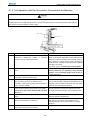
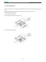
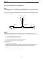
2.1.7 Install to the Client
When the servo motor is mounted to the client, please firmly secure the servo motor by the screws with backing ring
as shown in the figure.
2.2 Servo Drive
ProNet series servo drive is a base-mounted type. Incorrect installation will cause problems. Always observe the
installation instructions described below.
2.2.1 Storage
When the servomotor is not being used, store it in an area with a temperature between -25℃ and 85℃ with the
power cable disconnected.
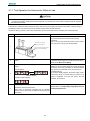
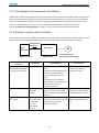
2.2.2 Installation Sites
Notes on installation are shown below.
Situation
Notes on installation
When installed in a control
Design the control panel size, unit layout, and cooling method so that the temperature
panel
around the periphery of the servo drive does not exceed 55℃.
When installed near a
heating unit
When installed near a
source of vibration
Suppress radiation heat from the heating unit and a temperature rise caused by
convection so that the temperature around the periphery of the servo drive does not
exceed 55℃.
Install a vibration isolator underneath the servo drive to prevent it from receiving vibration.
When installed in a location
Take appropriate action to prevent corrosive gases. Corrosive gases do not immediately
subject to corrosive gases
affect the servo drive, but will eventually cause contactor-related devices to malfunction.
Others
Avoid installation in a hot and humid site or where excessive dust or iron powder is
present in the air.
- 25 -
ProNet Series AC Servo User's Manual
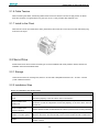
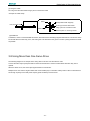
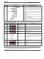
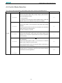
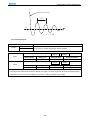
2.2.3 Installation Orientation
Install the servo drive perpendicular to the wall as shown in the figure. The servo drive must be oriented this way
because it is designed to be cooled by natural convection or a cooling fan if required. Firmly secure the servo drive
through two mounting holes.
Wall
Ventilation
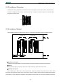
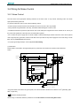
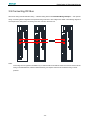
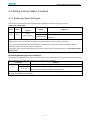
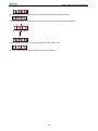
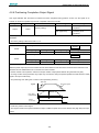
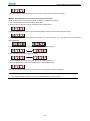
2.2.4 Installation Method
When installing multiple servo drives side by side in a control panel, observe the following installation method.
CollingFan
Fan
Cooling
Colling Fan
Cooling
Fan
■Installation Orientation
Install servo drive perpendicular to the wall so that the front panel (containing connectors) faces outward.
■Cooling
Provide sufficient space around each servo drive to allow cooling by natural convection or fans.
■Installing side by side
When installing servo drives side by side, provide at least 10mm space between each individual servo drive and at
least 50mm space above and below each one as well as shown in the figure above. Ensure the temperature inside the
control panel is evenly distributed, and prevent the temperature around each servo drive from increasing excessively.
- 26 -
ProNet Series AC Servo User's Manual
Install cooling fans above the servo drives if necessary.
■Working conditions
1.Temperature:0~ 55 ℃
2.Humidity:5%~95%RH
2
3.Vibration:4.9m/s or less
4.Ambient temperature to ensure long-term reliability: 45
5.Condensation and Freezing: None
- 27 -
℃ or less
ProNet Series AC Servo User's Manual
Chapter 3
Wiring
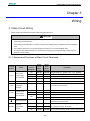
3.1 Main Circuit Wiring
Please observe the following instructions while wiring the main circuit.
!CAUTION
· Do not bundle or run power and signal lines together in the same duct. Keep power and signal lines
separated by at least 300 mm.
· Use twisted-pair shielded wires or multi-core twisted-pair shielded wires for signal and encoder feedback
lines.
· The maximum length is 3 m for reference input lines and 20 m for encoder feedback lines.
· Do not touch the power terminals for 5 minutes after turning power OFF because high voltage may still
remain in the servo drive.
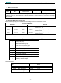
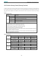
3.1.1 Names and Functions of Main Circuit Terminals
Terminal
Symbol
L1,L2
FG
Name
Main circuit
power supply
input terminal
FG
Main
Circuit
Voltage(V)
Servo
Drive
Model
ProNet-
Servo
Drive
Model
Pronet-E-
100
02B-08B
02B-08B
Single-phase 100~120VAC +10%~-15% (50/60Hz)
200
A5A-04A
A5A-04A
Single-phase 200~230VAC +10%~-15% (50/60Hz)
200
08A-50A
08A-50A
Three-phase 200~230VAC +10%~-15% (50/60Hz)
400
10D-2BD
10D-50D
Three-phase 380~440VAC +10%~-15% (50/60Hz)
200
A5A-04A
A5A-04A
Normally not connected.
-
-
-
100
02B-08B
02B-08B
Single-phase 100~120VAC +10%~-15% (50/60Hz)
200
A5A -50A
A5A -50A
Single-phase 200~230VAC +10%~-15% (50/60Hz)
75D-2BD
-
Single-phase 380~440VAC +10%~-15% (50/60Hz)
10D-70D
10D-50D
-
-
Functions
Servomotor
U,V,W
connection
Connect to the servomotor.
terminals
L1C,L2C
Control circuit
power supply
input terminal
24V,GND
Ground terminals
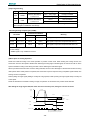
B1,B2,B3
400
-
24VDC +10%~-10%
Connects to the power supply ground terminals and
servomotor ground terminal.
External
100
02B
02B
regenerative
200
A5A -04A
A5A -04A
by customer) between B1 and B2.
resistor
100
04B-08B
04B-08B
If using an internal regenerative resistor, please short
- 28 -
Connect an external regenerative resistor(provided
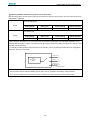
ProNet Series AC Servo User's Manual
Terminal
Symbol
Name
connection
Main
Circuit
Voltage(V)
Servo
Drive
Model
ProNet-
Servo
Drive
Model
Pronet-E-
Functions
200
08A-50A
08A-50A
B2 and B3. Remove the wire between B2 and B3 and
terminal
connect an external regenerative resistor(provided
10D-75D
10D-50D
the internal regenerative resistor is insufficient.
400
1AD-2BD
-
200
A5A-50A
A5A-50A
400
10D-75D
10D-50D
200
A5A-50A
A5A-50A
400
10D-75D
10D-50D
B1,B2
+ 1,○
+2
○
DC reactor for
harmonic
suppression
Main circuit
minus terminal
Connect an external regenerative resistor between
B1 and B2.
terminal
○
by customer) between B1 and B2, if the capacity of
Normally short ○
+ 1and ○
+ 2.
If a countermeasure against power supply harmonic
+
waves is needed, connect a DC reactor between ○
1and ○
+ 2.
Normally not connected.
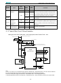
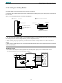
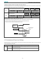
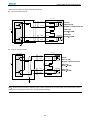
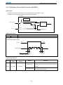
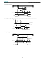
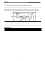
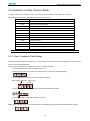
3.1.2 Typical Main Circuit Wiring Examples
Single-phase 200V ProNet-A5A~04A/ Single-phase 200V ProNet-E-A5A~04A
L1
Molded-case Circuit Breaker
Single-phase 200~230V-+10%
15% (50/60Hz)
L2
Surge Protector
1Ry
Noise Filter
Power OFF Power ON
1KM
1Ry
1PL (Servo Alarm Display)
1KM
1SUP
Be sure to connect a surge suppressor to the
excitation coil of the magnetic contactor and relay.
Magnetic Contactor
L1
ProNet
Series Servodrive
L2
A(1)
U
B(2)
V
1
Servodrive
M
C(3)
W
D(4)
2
L1C
L2C
Encoder
PG
CN2
External regenerator resistor
B1
B2
B3
B1
B2
B3
1Ry
7
8
+24V
ALM+
ALM1D
0V
Ground Terminal
Note
1.The L1,L2,L3 and L1C,L2C terminals wiring method of ProNet-A5A~04A/ProNet-E-A5A~04A servo drives is different
from other ProNet series servo drives. Please note the specific terminal definition while wiring.
2.The main circuit power supply of ProNet-A5A~04A/ProNet-E-A5A~04A is Single-phase 200V.
3. External regenerative resistor for ProNet-A5A~04A/ProNet-E-A5A~04A is provided by customer, the model of 60W,
- 29 -
ProNet Series AC Servo User's Manual
50Ωresistor is recommended.
4.Change Pn521.0 from “1” to “0” when using the external regenerative resistor in ProNet-A5A~04A/ProNet-E-A5A~04A
servo drives.
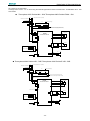
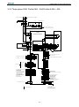
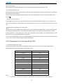
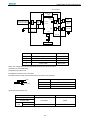
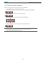
·Three-phase 200V ProNet-08A~50A/ Three-phase 200V ProNet-E-08A~50A
L1
L2
L3
+10%
Three-phase 200~230V -15% (50/60Hz)
Molded-case Circuit Breaker
Surge Protector
1PL (Servo Alarm Display)
1Ry
Noise Filter
Power OFF
Power ON
1KM
1KM
1Ry
Be sure to connect a surge suppressor to the
excitation coil of the magnetic contactor and relay. .
1SUP
Magnetic Contactor
L1
ProNet
Series Servodrives
L2
L3
B(2)
V
1
Servomotor
A(1)
U
M
C(3)
W
D(4)
2
L1 C
L2C
Encoder
PG
CN2
External Regenerator Resistor
B1
B1
B2
B2
B3
B3
1Ry
7
8
+24V
ALM+
ALM1D
Ground Terminal
0V
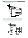
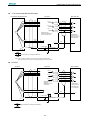
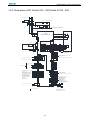
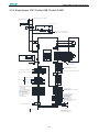
Three-phase 400V ProNet-10D~70D/ Three-phase 400V ProNet-E-10D~50D
L1
L2
L3
+10%
Three-phase 380~440V -15% (50/60Hz)
Molded-case Circuit Breaker
Surge Protector
1Ry
Noise Filter
Power OFF
Power ON
1KM
1Ry
1PL (Servo Alarm Display)
1KM
1SUP
Be sure to connect a surge suppressor to the
excitation coil of the magnetic contactor and relay..
Magnetic Contactor
L1
ProNet
Series Servodrives
L2
A(1)
U
L3
B(2)
V
1
D(4)
24V
GND
Encoder
PG
CN2
External Regenerator Resistor
M
C(3)
W
2
24VDC Power Supply
Servomotor
B1
B1
B2
B2
B3
B3
1Ry
7
8
+24V
ALM+
ALM1D
Ground Terminal
0V
- 30 -
ProNet Series AC Servo User's Manual
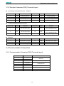
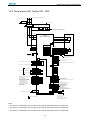
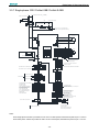
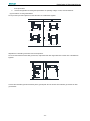
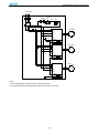
Three-phase 400V ProNet-75D~2BD
L1
Molded-case Circuit Breaker
L2
Three-phase 380~440V +-10%
15% (50/60Hz)
L3
Surge Protector
1PL (Servo Alarm Display)
1Ry
Noise Filter
Power OFF Power ON
1KM
1Ry
1KM
Be sure to connect a surge
suppressor to the excitation coil of
the magnetic contactor and relay.
1SUP
Magnetic Contactor
L1
ProNet
Series Servodrive
L2
L3
A(1)
U
Servodrive
B(2)
V
M
C(3)
W
D(4)
L1C
L2C
Encoder
PG
CN2
External Regenerative Resistor
B1
B2
1Ry
7
8
+24V
ALM+
ALM1D
0V
Ground Terminal
Notes:
1. A resistor value of 1500W/20Ω is recommended for the external regenerative resistor of ProNet-1AD.
2. A resistor value of 1500W/15Ω is recommended for the external regenerative resistor of ProNet-1ED.
3. A resistor value of 1500W/20Ω is recommended for the external regenerative resistor of ProNet-2BD.
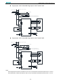
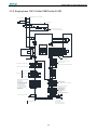
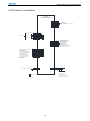
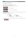
Single-phase 100V ProNet-02B /Single-phase 100V ProNet-E-02B
L1
Molded-case Circuit Breaker
+10%
L2
Single-phase 100~120V -15% (50/60Hz)
Surge Protector
1Ry
Noise Filter
Power OFF Power ON
1KM
1PL (Servo Alarm Display)
1KM
1Ry
1SUP
Be sure to connect a surge suppressor to the
excitation coil of the magnetic contactor and relay.
Magnetic Contactor
L1
A(1)
U
L2
B(2)
V
1
Servodrive
M
C(3)
W
D(4)
2
L1C
L2C
Encoder
PG
CN2
External regenerator resistor
B1
B2
B3
B1
B2
B3
1Ry
7
8
+24V
ALM+
ALM1D
0V
Ground Terminal
- 31 -
ProNet Series AC Servo User's Manual
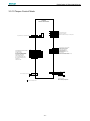
Single-phase 100V ProNet-04B /Single-phase 100V ProNet-E-04B
L1
Molded-case Circuit Breaker
+10%
L2
Single-phase 100~120V -15% (50/60Hz)
Surge Protector
1Ry
Noise Filter
Power OFF Power ON
1KM
1Ry
1PL (Servo Alarm Display)
1KM
1SUP
Be sure to connect a surge suppressor to the
excitation coil of the magnetic contactor and relay.
Magnetic Contactor
L1
A(1)
U
L2
1
Servodrive
B(2)
V
M
C(3)
W
D(4)
2
L1C
L2C
Encoder
PG
CN2
External regenerator resistor
B1
B1
B2
B2
B3
B3
1Ry
7
8
+24V
ALM+
ALM1D
0V
Ground Terminal
Single-phase 100V ProNet-08B /Single-phase 100V ProNet-E-08B
L1
Molded-case Circuit Breaker
+10%
L2
Single-phase 100~120V -15% (50/60Hz)
Surge Protector
1Ry
Noise Filter
Power OFF Power ON
1KM
1Ry
1PL (Servo Alarm Display)
1KM
1SUP
Be sure to connect a surge suppressor to the
excitation coil of the magnetic contactor and relay.
Magnetic Contactor
L1
A(1)
U
L2
B(2)
V
1
Servodrive
M
C(3)
W
D(4)
2
L1C
L2C
Encoder
PG
CN2
External regenerator resistor
B1
B2
B3
B1
B2
B3
1Ry
7
8
+24V
ALM+
ALM1D
0V
Ground Terminal
Notes:
When single-phase 100VAC is provided for main circuit on rated speed, instantaneous peak torque≤4.78 N.m.
When three-phase 100VAC is provided for main circuit on rated speed, instantaneous peak torque≤7.16 N.m.
- 32 -
ProNet Series AC Servo User's Manual
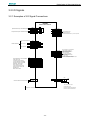
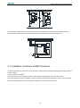
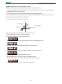
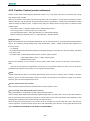
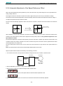
3.2 I/O Signals
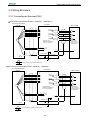
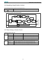
3.2.1 Examples of I/O Signal Connections
ProNet
Series Servodrive
P
10K
Speed Reference(±0~10V/Rated Speed)
VREF+
VREF-
1
2
40K
ref
+
40K
-
26
27
PPI
34
PULS+
PULS-
30
31
SIGN+
SIGN-
32
33
P
TREF+
TREF-
P
Torque Reference(±0~10V/Rated Torque)
P
10K
Open-Collector Reference
Use
Position Reference
PULS / CW / A
SIGN / CCW / B
+24V
Signal Allocations can be Modified:
S-ON: Servo ON
P-CON: Proportion Control
P-OT:Forward Run Prohibited
N-OT:Reverse Run Prohibited
ALM-RST: Alarm Reset
CLR: Clear Error Pulse
P-CL:Forward Torque Limit
N-CL:Reverse Torque Limit
SHOM: Home
ORG: Zero Position
DICOM
S-ON
P-CON
P-OT
N-OT
ALM-RST
CLR
P-CL
N-CL
13
14
15
16
17
39
40
41
42
A/D
ref
+
-
20
21
22
23
24
25
50
PAO+
PAOPBO+
PBOPCO+
PCODGND
5
6
9
10
11
12
TGON+
TGONS-RDY+
S-RDYV-CMP+
V-CMP-
7
8
ALM+
ALM-
PG Divided Ratio Output
Applicable Line Output
AM26LS32A Manufactured by TI or the Equivalent.
2KΩ
150Ω
2KΩ
150Ω
Signal Allocations can be Modified:
V-CMP: Speed Coincidence
COIN: Positioning Completion
TGON:Rotation Detection
S-RDY:Servo Ready
CLT:Torque Limit Detection
BK:Brake Interlock
PGC: Encoder C-Pulse Output
OT: Over Travel
RD: Servo Enabled Motor Excitation Output
HOME: Home Completion Output
3.3KΩ
1Ry
Connect Shield to Connector Shell
Shield
+24V
1D
0V
P
ALM: Servo Alarm Output
Photocoupler Output:
Maximum Operating Voltage:DC30V
Maximum Output Current:DC50mA
Represents Twisted-pair Wires
- 33 -
ProNet Series AC Servo User's Manual
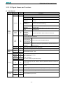
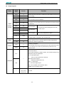
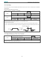
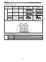
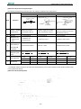
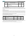
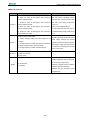
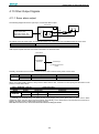
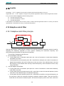
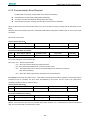
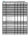
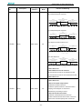
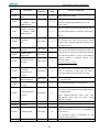
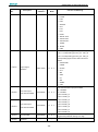
3.2.2 I/O Signal Names and Functions
Input Signals
Control
Signal
Mode
Name
Speed
Position
Torque
Pin
No.
Function
/S-ON
14
Servo ON: Turns the servomotor on.
Function selected by parameter.
Proportional
Switches the speed control loop from PI to P control when
control reference
ON.
Direction
With the internally set speed selection: Switch the rotation
reference
direction.
/P-CON
15
Control mode
switching
P-OT
N-OT
16
17
Enables control mode switching.
Zero-clamp
reference
Reference pulse
block
Forward run
prohibited
Reverse run
prohibited
Speed control with zero-clamp function: Reference speed is
zero when ON.
Position control with reference pulse: Stops reference pulse
input when ON.
Overtravel prohibited: Stops servomotor when OFF.
Function selected by parameter.
/PCL
/NCL
Speed
Position
41
42
Forward external
torque limit ON
Reverse external
torque limit ON
Current limit function enabled when ON.
Internal speed
switching
With the internally set speed selection: Switches the internal
speed settings.
/ALM-RST
39
Alarm reset: Releases the servo alarm state.
DICOM
13
Control power supply input for I/O signals: Provide the +24V DC power supply
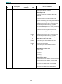
VREF+
1
VREF-
2
PULS+
30
PULS-
31
SIGN+
32
SIGN-
33
PPI
34
Power supply input for open collector reference (2KΩ/0.5W resistor is built into the
servo drive).
/CLR
40
Positional error pulse clear input: Clear the positional error pulse during position
control.
SHOM
-
Homing trigger signal(effective at the rising edge),allocated by Pn509 or Pn510
ORG
-
Zero Position(effective at high level), allocated by Pn509 or Pn510
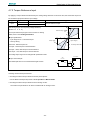
T-REF+
26
T-REF-
27
Torque
Speed reference input: ±10V.
Pulse reference input mode:
Sign + pulse train
CCW + CW pulse
Two-phase pulse (90º phase differential)
Torque reference input: ±10V.
- 34 -
ProNet Series AC Servo User's Manual
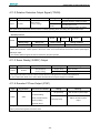
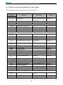
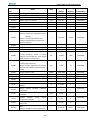
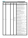
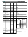
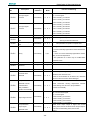
Output signals
Control
Mode
Signal
Name
Pin No.
Function
/TGON+
5
Detects when the servomotor is rotating at a speed higher than the motor
/TGON-
6
speed seeting.
ALM+
7
Servo alarm:
ALM-
8
Turns off when an error is detected.
/S-RDY+
9
Servo ready:
/S-RDY-
10
Position
PAO+
20
Torque
PAO-
21
PBO+
22
PBO-
23
PCO+
24
PCO-
25
FG
Shell
/V-CMP+
11
/V-CMP-
12
/COIN+
11
Speed
ON if there is no servo alarm when the control/main circuit power supply
is turned ON.
Phase-A signal
Converted two-phase pulse(phases A and B)
Phase-B signal
Phase-C signal
encoder output.
Zero-point pulse(Phase-C) signal
Connect frame to ground if the shield wire of the
I/O signal cable is connected to the connector shell.
Speed coincidence:
Detects whether the motor speed is within the setting range and if it
Speed
matches the reference speed value.
Positioning completion:
Turns ON when the number of positional error pulses reaches the value
Position
/COIN-
12
set. The setting is the number of positional error pulses set in the
reference units.
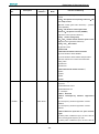
Reserved terminals:
The functions allocated to /TGON, /S-RDY, and /V-CMP (/COIN) can be
/CLT
changed by using the parameters.
/CLT: Torque limit output
Turns on when it reaches the value set.
—
/BK: Brake interlock output
Releases the brake when ON,
Reserved
/PGC:C pulse output
/BK
OT:Over travel signal output
/RD:Servo enabled motor excitation output
/HOME: Home completion output
4,18,19,29,35
—
36,37,38,43
Not used.
44,45,47,49
- 35 -
ProNet Series AC Servo User's Manual
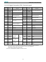
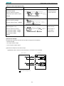
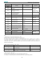
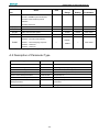
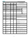
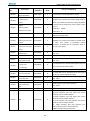
3.2.3 I/O Signal Connector (CN1) Terminal Layout
Terminal
No.
Name
1
VREF+
2
VREF-
3
DGND
4
—
5
/TGON+
6
/TGON-
7
ALM+
8
ALM-
9
/S-RDY+
10
/S-RDY-
11
/COIN+
12
/COIN-
13
DICOM
14
/S-ON
15
/P-CON
16
Terminal
Function
No.
Name
Function
26
T-REF+
27
T-REF-
DGND
28
DGND
Reserved
29
—
30
PULS+
31
PULS-
32
SIGN+
33
SIGN-
34
PPI
35
—
Reserved
36
—
Reserved
37
—
Reserved
38
—
Reserved
Servo ON
39
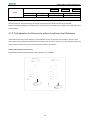
/ALM-RST
P/PI control input
40
/CLR
Position error pulse clear input
P-OT
Forward run prohibited
41
/PCL
Forward torque limit input
17
N-OT
Reverse run prohibited
42
/NCL
Reverse torque limit input
18
—
Reserved
43
—
Reserved
19
—
Reserved
44
—
Reserved
20
PAO+
PG dividing
45
—
Reserved
21
PAO-
46
DGND
22
PBO+
47
—
23
PBO-
48
DGND
24
PCO+
49
—
25
PCO-
50
DGND
Speed reference input:±10V
Running signal output
Servo alarm
Servo ready
Positioning completion
I/O signal power supply 24V
DC
pulse output
PG
phase A
dividing
PG dividing
pulse
pulse output
output
phase B
PG dividing
pulse output
phase C
Zero-point
pulse
Torque referenceinput:±10V
DGND
Reserved
Reference pulse input
Reference sign input
Open collector reference
power supply
Alarm reset
DGND
Reserved
DGND
Reserved
DGND
Note: The functions allocated to the following input and output signals can be changed by using the parameters.
·Input signals: /S-ON,/P-CON,P-OT,N-OT,/ALM-RST,/CLR,/PCL,/NCL,SHOM,ORG
·Output signals: /TGON,/S-RDY,/COIN,/HOME
Please refer to A.3 Parameters in details for detailed information.
- 36 -
ProNet Series AC Servo User's Manual
3.2.4 Interface Circuit
This section shows examples of servo drive I/O signal connection to the host controller.
■Interface for Analog Reference Input Circuit
Analog signals are either speed or torque reference signals at about 40kΩ impedance, and the maximum allowable
voltages for input signals is ±10V.
Reference speed input
Reference torque input
Servodrive
Servodrive
470Ω(1/2W)min.
470Ω(1/2W)min.
3
10V
3
2
2KΩ
V-REF
10V
2
2KΩ
T-REF
About 40KΩ
1
About 40KΩ
1
GND
GND
0V
0V
■Interface for sequence input circuit
The sequence input circuit interface connects through a relay or open-collector transistor circuit. Select a low-current relay
otherwise a faulty contact will result.
Servodrive
Servodrive
DC24V
50mA min.
+24VIN
DC24V
50mA min.
3.3KΩ
/S-ON,etc.
+24VIN
3.3KΩ
/S-ON,etc.
■Interface for line driver output circuit
The amount of two-phase (phase A and phase B) pulse output signals (PAO,/PAO,PBO,/PBO) and zero-point pulse
signals (PCO,/PCO) are output via line-driver output circuits. Normally, the servo drive uses this output circuit in speed
control to comprise the position control system at the host controller. Connect the line-driver output circuit through a line
receiver circuit at the host controller.
■Interface for sequence output circuit
Photocoupler output circuits are used for Servo Alarm (ALM), Servo Ready(S-RDY), and other sequence output signal
circuits. Connect a photocoupler output circuit through a relay circuit.
- 37 -
ProNet Series AC Servo User's Manual
3.3 Wiring Encoders
3.3.1 Connecting an Encoder(CN2)
■
Wire-saving Incremental Encoder(2500P/R)
(Waterproof)
Wire-saving Incremental
Encoder
Servodrive
*
PA
1(A)
P
2(B)
Host controller
1CN
2CN
3(C)
4(D)
5(E)
P
6(F)
P
*
2-1
/PA
2-2
PB
2-3
/PB
PC
2-4
2-5
2-6
/PC
Phase-A
Phase-B
Phase-C
PG
PAO
21
/PAO
22
PBO
23
/PBO
24
PCO
25
/PCO
P
P
P
Output line driver
AM26LS31 manufactured
by TI or the equivalent.
7(H)
8(G)
P
*
1-18
1-36
SG
0V
Connector shell
FG
9(J)
Connector shell
shielded wires
(Shell)
Applicable linereceiver SN75175
manufactured by TI
or the equivalent.
2-7、2-8、2-9
PG5V
2-17、2-18、2-19
PG0V
0V
■
20
Represents multi-core twisted pair shielded wires.
Wire-saving Incremental Encoder(2500P/R)
(Standard)
Wire-saving Incremental
Encoder
Servodrive
*
2CN
PA
1(A)
4(B)
Host controller
1CN
P
2(C)
5(D)
3(E)
P
6(F)
P
*
2-1
/PA
2-2
PB
2-3
/PB
PC
2-4
2-5
2-6
/PC
Phase-A
Phase-B
Phase-C
20
PAO
21
/PAO
22
PBO
23
/PBO
24
PCO
25
/PCO
P
P
P
PG
Output line driver
AM26LS31 manufactured
by TI or the equivalent.
7(H)
8(G)
2-7、2-8、2-9
PG5V
2-17、2-18、2-19
PG0V
0V
FG
9(J)
(Shell)
*
P
Applicable linereceiver SN75175
manufactured by TI
or the equivalent.
1-18
1-36
Connector shell
Connector shell
shielded wires
Represents multi-core twisted pair shielded wires.
- 38 -
SG
0V
ProNet Series AC Servo User's Manual
17 bit Incremental/Absolute Encoders
Incremental/Absolute Encoders
Servodrive
*
K(1)
PS
P
L(2)
T(3)
P
S(4)
Host controller
CN1
CN2
*
7
Phase-A
/PS
8
BAT+
17
BAT-
18
Phase-B
Phase-C
PG
20
PAO
21
/PAO
22
PBO
23
/PBO
24
PCO
25
/PCO
P
P
P
Output line driver
AM26LS31 manufactured
by TI or the equivalent.
H(5)
PG5V
G(6)
PG0V
Applicable linereceiver SN75175
manufactured by TI
or the equivalent.
9
19
50
0V
FG
J(7)
DGND
0V
Connector shell
shielded wires
Connector shell
(Shell)
P
*
Represents multi-core twisted pair shielded wires.
Note: (1)BAT+ and BAT- signals are not used when using an incremental encoder .
(2)The pin numbers for the connector wiring differ depending on the servomotors .
Resolver
Resolver
Servodrive
*
K
L
SIN+
P
T
S
Host controller
CN1
CN2
P
*
7
SIN-
8
COS+
17
COS-
18
Phase-A
Phase-B
Phase-C
PG
PAO
21
/PAO
22
PBO
23
/PBO
24
PCO
25
/PCO
Output line-driver
AM26LS31
manufactured by TI
or equivalent.
H
R1
G
R2
FG
J
P
P
9
19
Connect shell
shielded wires
Connector shell
(Shell)
P
P
Applicable linereceiver SN75175
manufactured by
TI or equivalent.
0V
*
20
Represents multi-core twisted pair shielded wires.
- 39 -
50
DGND
0V
ProNet Series AC Servo User's Manual
3.3.2 Encoder Connector(CN2) Terminal Layout
Wire-saving Incremental Encoder(2500P/R)
Terminal No.
Name
Function
1
PA
PG input phase A
2
/PA
3
4
Terminal No.
Name
Function
5
PC
PG input phase B
PG input phase /A
6
/PC
PG input phase /B
PB
PG input phase B
7,8,9
/PB
PG input phase /B
17,18,19
PG5V
PG power supply +5V
SG
PG power supply 0V
17 Bit Incremental/ Absolute Encoder
Terminal No.
Name
Function
Terminal No.
Name
Function
7
PS
PG serial signal input
17
BAT+
8
/PS
PG serial signal input
18
BAT-
9
PG5V
PG power supply +5V
19
GND
PG power supply 0V
Terminal No.
Name
Function
Terminal No.
Name
Function
7
SIN+
Differential Sine Signal
17
COS+
Differential Cosine Signal
8
SIN-
Differential Sine Signal
18
COS-
Differential Cosine Signal
9
R1
Excitation signal
19
R2
Excitation Signal
Battery(+)
(For an absolute encoder)
Battery(-)
(For an absolute encoder)
Resolver
3.4 Communication Connection
3.4.1 Communication Connector(CN3) Terminal Layout
Terminal No.
Name
Function
1
—
2
—
3
485+
4
ISO_GND
5
ISO_GND
6
485-
RS-485 communication terminal
7
CANH
CAN communication terminal
8
CANL
CAN communication terminal
Reserved
RS-485 communication terminal
Isolated ground
Note: Do not short terminal 1 and 2 of CN3.
- 40 -
ProNet Series AC Servo User's Manual
3.4.2 Communication Connector(CN4) Terminal Layout
Terminal No.
Name
Function
1
—
2
—
3
485+
4
ISO_GND
5
ISO_GND
6
485-
RS-485 communication terminal
7
CANH
CAN communication terminal
8
CANL
CAN communication terminal
Reserved
RS-485 communication terminal
Isolated ground
- 41 -
ProNet Series AC Servo User's Manual
3.5 Standard Wiring Examples
3.5.1 Single-phase 200V ProNet-A5A~04A/ProNet-E-A5A~04A
L1
single-phase 200~230V +10%
-15% (50/60Hz)
L2
Molded-case Circuit Breaker
Surge Protector
1PL (Servo Alarm Display )
1Ry
Noise Filter
Power OFF Power ON
1KM
1KM
1Ry
1SUP
Be sure to connect a surge suppressor to the
excitation coil of the magnetic contactor and relay.
Magnetic Contactor
ProNet
Series Servodrives
L1
A(1)
U
B(2)
V
L2
1
Servomotor
M
C(3)
W
D(4)
2
CN2
Option
L1C
Incremental Wire-saving
Encoder(2500P/R)
L2C
1
2
3
4
5
6
A+
AB+
BC+
C7,8,9
PG5V
17,18,19
PG0V
Shell Shield
External Regenerator Resistor
B1
B1
B2
B2
B3
B3
Serial Encoder
Encoder
7
8
17
18
9
19
S+
SBAT+
BATPG5V
PG0V
Shell
Shield
PG
CN3
1
2
3
4
5
6
7
8
N.C.
N.C.
485+
ISO_GND
ISO_GND
485CANH
CANL
Shell
Shield
Be sure to ground
CN1
10K
1
2
Torque Reference (±0~10V / Rated Torque)
TREF+
TREF-
26
27
P
Speed Reference(±0~10V/Rated Speed)
VREF+
VREF-
40K
ref
+
40K
-
P
10K
A/D
ref
+
Be sure to prepare the end of the
shielded wire properly.
Use special communication cable to connect
PC(Personal Computer).
Note: Do not short terminal 1 and 2 of CN3.
-
PPI
34
P
PULS+
PULS-
30
31
P
CN4
SIGN+
SIGN-
32
33
DICOM
S-ON
P-CON
P-OT
N-OT
ALM-RST
CLR
P-CL
N-CL
13
14
15
16
17
39
40
41
42
Open-collector Reference Use
Position Reference
PULS / CW / A
SIGN / CCW / B
Signal allocatons can be modified:
S-ON: Servo ON
P-CON: P Control
P-OT: Forward Run Prohibited
N-OT: Reverse Run Prohibited
ALM-RST: Alarm Reset
CLR: Clear Error Pulse
P-CL: Forward Torque Limit
N-CL: Reverse Torque Limit
SHOM: Home
ORG: Zero Position
+24V
2KΩ
150Ω
2KΩ
150Ω
3.3KΩ
1
2
3
4
5
6
7
8
N.C.
N.C.
485+
ISO_GND
ISO_GND
485CANH
CANL
Shell
Shield
20
21
22
23
24
25
50
PAO+
PAOPBO+
PBOPCO+
PCODGND
5
6
9
10
11
12
TGON+
TGONS-RDY+
S-RDYV-CMP+
V-CMP-
7
8
ALM+
ALM-
PG Divided Ratio Output:
Applicable Line Receiver
AM26LS32A Manufactured by TI or the Equivalent.
Signal Allocations can be Modified:
V-CMP: Speed Coincidence
COIN: Positioning Completion
TGON:Rotation Detection
S-RDY:Servo Ready
CLT:Torque Limit Detection
BK:Brake Interlock
PGC: Encoder C-Pulse Output
OT:Over Travel
RD: Servo Enabled Motor Excitation Output
HOME: Home Completion Output
1Ry
Connect Shield to Connector Shell.
Shield
Shell
+24V
1D
0V
P
ALM: Servo Alarm Output
Represents Twisted-pair Wires
Photocoupler Output:
Maximum Operating Voltage:DC30V
Maximum Output Current:DC50mA
Note 1.The L1,L2,L3 and L1C,L2C terminals wiring method of ProNet-A5A~04A/ProNet-E-A5A~04A servo drives is
different from other ProNet series servo drives. Please note the specific terminal definition while wiring.
2.The main circuit power supply of ProNet-A5A~04A/ProNet-E-A5A~04A is Single-phase 200V
3. External regenerative resistor for ProNet-A5A~04A/ProNet-E-A5A~04A is provided by customer, the model of
60W,50Ωresistor is recommended.
4.Change Pn521.0 from “1” to “0” when using the external regenerative resistor in ProNet- A5A~04A /ProNet-EA5A~04A servo drives.
- 42 -
ProNet Series AC Servo User's Manual
3.5.2 Three-phase 200V ProNet-08A~50A/ProNet-E-08A~50A
L1
L2
L3
Three-phase 200~230V
+10%
-15%
(50/60Hz)
Molded-case Circuit Breaker
Surge Protector
1PL ( Servo Alarm Display )
1Ry
Noise Filter
Power OFF
Power ON
1KM
1Ry
1KM
Be sure to connect a surge suppressor to the
excitation coil of the magnetic contactor and relay.
1SUP
Magnetic Contactor
L1
ProNet
Series Servodrives
L2
A(1)
U
L3
B(2)
V
1
Servomotor
M
C(3)
W
D(4)
2
CN2
Option
L1C
Incremental Wire-saving
Encoder(2500P/R)
L2C
B1
A+
AB+
BC+
C7,8,9
PG5V
17,18,19
PG0V
Shell Shield
1
2
3
4
5
6
B1
B2
B2
B3
B3
External Regenerator Resisotr
Serial Encoder
Encoder
Resolver
7
8
17
18
9
19
SIN+
SINCOS+
COSR1
R2
Shell
Shield
7
8
17
18
9
19
S+
SBAT+
BATPG5V
PG0V
Shell
Shield
CN3
Be sure to ground
N.C.
1
N.C.
2
3
485+
4 ISO_GND
5 ISO_GND
6
4857
CANH
8
CANL
CN1
P
10K
Speed Reference(±0~10V/Rated Speed)
VREF+
VREF-
1
2
TREF+
TREF-
26
27
40K
ref
+
40K
-
P
10K
Torque Reference (±0~10V/Rated Torque)
PG
A/D
ref
Shell
+
Be sure to prepare the end of the
shielded wire properly.
Use special communication cable to connect
PC(Personal Computer).
Note: Do not short terminal 1 and 2 of CN3.
Shield
-
PPI
34
P
PULS+
PULS-
30
31
P
CN4
SIGN+
SIGN-
32
33
DICOM
S-ON
P-CON
P-OT
N-OT
ALM-RST
CLR
P-CL
N-CL
13
14
15
16
17
39
40
41
42
Open-collector Reference Use
Position Reference
PULS / CW / A
SIGN / CCW / B
Signal allocatons can be modified:
S-ON: Servo ON
P-CON: P Control
P-OT: Forward Run Prohibited
N-OT: Reverse Run Prohibited
ALM-RST: Alarm Reset
CLR: Clear Error Pulse
P-CL: Forward Torque Limit
N-CL: Reverse Torque Limit
SHOM: Home
ORG: Zero Position
+24V
1
N.C.
2
N.C.
3
485+
4 ISO_GND
5 ISO_GND
6
4857
CANH
8
CANL
2KΩ
150Ω
2KΩ
150Ω
3.3KΩ
Shell
Shield
20
21
22
23
24
25
50
PAO+
PAOPBO+
PBOPCO+
PCODGND
5
6
9
10
11
12
TGON+
TGONS-RDY+
S-RDYV-CMP+
V-CMP-
7
8
ALM+
ALM-
PG Divided Ratio Output:
Applicable Line Receiver
AM26LS32A Manufactured by TI or the Equivalent.
Signal Allocations can be Modified:
V-CMP: Speed Coincidence
COIN: Positioning Completion
TGON:Rotation Detection
S-RDY:Servo Ready
CLT:Torque Limit Detection
BK:Brake Interlock
PGC: Encoder C-Pulse Output
OT:Over Travel
RD: Servo Enabled Motor Excitation Output
HOME: Home Completion Output
1Ry
Connect Shield to Connector Shell.
Shield
Shell
+24V
1D
0V
P
ALM: Servo Alarm Output
Represents Twisted-pair Wires
Photocoupler Output:
Maximum Operating Voltage:DC30V
Maximum Output Current:DC50mA
- 43 -
ProNet Series AC Servo User's Manual
3.5.3 Three-phase 400V ProNet-10D~70D/ProNet-E-10D~50D
L1
L2
Three-phase 380~440V +-10%
15% (50/60Hz)
L3
Molded-case Circuit Breaker
Surge Protector
1PL (Servo Alarm Display)
1Ry
Noise Filter
Power OFF Power ON
1KM
1Ry
1KM
1SUP
Be sure to connect a surge suppressor to the
excitation coil of the magnetic contactor and relay.
Magnetic Contactor
L1
ProNet
Series Servodrives
L2
A(1)
U
L3
B(2)
V
1
Servomotor
M
C(3)
W
D(4)
2
CN2
Option
24V
24VDC Power Supply
Incremental Wire-saving
Encoder(2500P/R)
GND
1
2
3
4
5
6
A+
AB+
BC+
C7,8,9
PG5V
17,18,19
PG0V
Shell Shield
B1
B1
B2
B2
B3
B3
External Regenerator Resisotr
Serial Encoder
Encoder
Resolver
7
8
17
18
9
19
SIN+
SINCOS+
COSR1
R2
Shell
Shield
7
8
17
18
9
19
S+
SBAT+
BATPG5V
PG0V
Shell
Shield
CN3
Be sure to ground
1
N.C.
2
N.C.
3
485+
4 ISO_GND
5 ISO_GND
6
4857
CANH
8
CANL
CN1
P
10K
Speed Reference(±0~10V/Rated Speed)
VREF+
VREF-
1
2
TREF+
TREF-
26
27
40K
ref
+
40K
-
P
10K
Torque Reference (±0~10V/Rated Torque)
PG
A/D
ref
Shell
+
Be sure to prepare the end of the
shielded wire properly.
Use special communication cable to connect
PC(Personal Computer).
Note: Do not short terminal 1 and 2 of CN3.
Shield
-
PPI
34
P
PULS+
PULS-
30
31
P
CN4
SIGN+
SIGN-
32
33
DICOM
S-ON
P-CON
P-OT
N-OT
ALM-RST
CLR
P-CL
N-CL
13
14
15
16
17
39
40
41
42
Open-collector Reference Use
Position Reference
PULS / CW / A
SIGN / CCW / B
Signal allocatons can be modified:
S-ON: Servo ON
P-CON: P Control
P-OT: Forward Run Prohibited
N-OT: Reverse Run Prohibited
ALM-RST: Alarm Reset
CLR: Clear Error Pulse
P-CL: Forward Torque Limit
N-CL: Reverse Torque Limit
SHOM: Home
ORG: Zero Position
+24V
1
N.C.
N.C.
2
3
485+
4 ISO_GND
ISO_GND
5
6
4857
CANH
8
CANL
2KΩ
150Ω
2KΩ
150Ω
3.3KΩ
Shell
Shield
20
21
22
23
24
25
50
PAO+
PAOPBO+
PBOPCO+
PCODGND
5
6
9
10
11
12
TGON+
TGONS-RDY+
S-RDYV-CMP+
V-CMP-
7
8
ALM+
ALM-
PG Divided Ratio Output:
Applicable Line Receiver
AM26LS32A Manufactured by TI or the Equivalent.
Signal Allocations can be Modified:
V-CMP: Speed Coincidence
COIN: Positioning Completion
TGON:Rotation Detection
S-RDY:Servo Ready
CLT:Torque Limit Detection
BK:Brake Interlock
PGC: Encoder C-Pulse Output
OT:Over Travel
RD: Servo Enabled Motor Excitation Output
HOME: Home Completion Output
1Ry
Connect Shield to Connector Shell.
Shield
Shell
+24V
1D
0V
P
ALM: Servo Alarm Output
Represents Twisted-pair Wires
Photocoupler Output:
Maximum Operating Voltage:DC30V
Maximum Output Current:DC50mA
- 44 -
ProNet Series AC Servo User's Manual
3.5.4 Three-phase 400V ProNet-75D~2BD
L1
L2
Three-phase 380~440V +-10%
15% (50/60Hz)
L3
Molded-case Circuit Breaker
Surge Protector
1Ry
Noise Filter
Power OFF Power ON
1KM
1Ry
1KM
1PL (Servo Alarm Display )
1SUP
Be sure to connect a surge suppressor to the
excitation coil of the magnetic contactor and relay.
Magnetic Contactor
L1
ProNet
Series Servodrives
L2
A(1)
U
B(2)
V
L3
Servomotor
M
C(3)
W
D(4)
CN2
L 1C
Option
Resolver
1 Sensor 1
3 Sensor 2
7
SIN+
8
SIN17
COS+
18
COS9
R1
19
R2
L2C
B1
External Regenerator Resisotr
B2
Shell
Shield
Serial Encoder
Encoder
7
8
17
18
9
19
S+
SBAT+
BATPG5V
PG0V
Shell
Shield
CN3
Be sure to ground
1
2
3
4
5
6
7
8
N.C.
N.C.
485+
ISO_GND
ISO_GND
485CANH
CANL
Shell
Shield
CN1
P
10K
Speed Reference(±0~10V/Rated Speed)
VREF+
VREF-
1
2
TREF+
TREF-
26
27
40K
ref
+
40K
-
P
10K
Torque Reference (±0~10V/Rated Torque)
PG
A/D
ref
+
Be sure to prepare the end of the
shielded wire properly.
Use special communication cable to connect
PC(Personal Computer).
Note: Do not short terminal 1 and 2 of CN3.
-
PPI
34
P
PULS+
PULS-
30
31
P
CN4
SIGN+
SIGN-
32
33
DICOM
S-ON
P-CON
P-OT
N-OT
ALM-RST
CLR
P-CL
N-CL
13
14
15
16
17
39
40
41
42
Open-collector Reference Use
Position Reference
PULS / CW / A
SIGN / CCW / B
Signal allocatons can be modified: +24V
S-ON: Servo ON
P-CON: P Control
P-OT: Forward Run Prohibited
N-OT: Reverse Run Prohibited
ALM-RST: Alarm Reset
CLR: Clear Error Pulse
P-CL: Forward Torque Limit
N-CL: Reverse Torque Limit
SHOM: Home
ORG: Zero Position
2KΩ
150Ω
2KΩ
150Ω
3.3KΩ
1
2
3
4
5
6
7
8
N.C.
N.C.
485+
ISO_GND
ISO_GND
485CANH
CANL
Shell
Shield
20
21
22
23
24
25
50
PAO+
PAOPBO+
PBOPCO+
PCODGND
5
6
9
10
11
12
TGON+
TGONS-RDY+
S-RDYV-CMP+
V-CMP-
7
8
ALM+
ALM-
PG Divided Ratio Output:
Applicable Line Receiver
AM26LS32A Manufactured by TI or the Equivalent.
Signal Allocations can be Modified:
V-CMP: Speed Coincidence
COIN: Positioning Completion
TGON:Rotation Detection
S-RDY:Servo Ready
CLT:Torque Limit Detection
BK:Brake Interlock
PGC: Encoder C-Pulse Output
OT:Over Travel
RD: Servo Enabled Motor Excitation Output
HOME: Home Completion Output
1Ry
Connect Shield to Connector Shell.
Shield
Shell
+24V
1D
0V
P
ALM: Servo Alarm Output
Represents Twisted-pair Wires
Photocoupler Output:
Maximum Operating Voltage:DC30V
Maximum Output Current:DC50mA
Notes:
1. The resistor of 1500W/20Ω is recommended for the external regenerative resistor of ProNet-1AD.
2. The resistor of 1500W/15Ω is recommended for the external regenerative resistor of ProNet-1ED.
3. The resistor of 1500W/20Ω is recommended for the external regenerative resistor of ProNet-2BD.
- 45 -
ProNet Series AC Servo User's Manual
3.5.5 Single-phase 100V ProNet-02B/ProNet-E-02B
L1
10%
single-phase 100~120V +-15%
(50/60Hz)
L2
Molded-case Circuit Breaker
Surge Protector
1PL ( Servo Alarm Display )
1Ry
Noise Filter
Power OFF Power ON
1KM
1Ry
1KM
1SUP
Be sure to connect a surge suppressor to the
excitation coil of the magnetic contactor and relay.
L1
A(1)
U
B(2)
V
L2
M
C(3)
W
1
Servomotor
D(4)
2
CN2
Option
L1C
Serial Encoder
L2C
External Regenerator Resistor
B1
B1
B2
B2
B3
7
8
17
18
9
19
S+
SBAT+
BATPG5V
PG0V
Shell
Shield
B3
Incremental Wire-saving
Encoder(2500P/R)
1
2
3
4
5
6
7,8,9
A+
AB+
BC+
CPG5V
17,18,19 PG0V
Shell Shield
Encoder
PG
CN3
1
N.C.
2
N.C.
3
485+
4 ISO_GND
5 ISO_GND
6
4857
CANH
8
CANL
Be sure to ground
CN1
10K
1
2
Torque Reference (±0~10V / Rated Torque)
TREF+
TREF-
26
27
P
Speed Reference(±0~10V/Rated Speed)
VREF+
VREF-
40K
ref
+
40K
-
P
10K
A/D
ref
Shell
+
Be sure to prepare the end of the
shielded wire properly.
Use special communication cable to connect
PC(Personal Computer).
Note: Do not short terminal 1 and 2 of CN3.
Shield
-
PPI
34
P
PULS+
PULS-
30
31
P
CN4
SIGN+
SIGN-
32
33
DICOM
S-ON
P-CON
P-OT
N-OT
ALM-RST
CLR
P-CL
N-CL
13
14
15
16
17
39
40
41
42
Open-collector Reference Use
Position Reference
PULS / CW / A
SIGN / CCW / B
Signal allocatons can be modified:
S-ON: Servo ON
P-CON: P Control
P-OT: Forward Run Prohibited
N-OT: Reverse Run Prohibited
ALM-RST: Alarm Reset
CLR: Clear Error Pulse
P-CL: Forward Torque Limit
N-CL: Reverse Torque Limit
SHOM: Home
ORG: Zero Position
+24V
1
N.C.
2
N.C.
3
485+
4 ISO_GND
5 ISO_GND
6
4857
CANH
8
CANL
2KΩ
150Ω
2KΩ
150Ω
3.3KΩ
Shell
Shield
20
21
22
23
24
25
50
PAO+
PAOPBO+
PBOPCO+
PCODGND
5
6
9
10
11
12
TGON+
TGONS-RDY+
S-RDYV-CMP+
V-CMP-
7
8
ALM+
ALM-
PG Divided Ratio Output:
Applicable Line Receiver
AM26LS32A Manufactured by TI or the Equivalent.
Signal Allocations can be Modified:
V-CMP: Speed Coincidence
COIN: Positioning Completion
TGON:Rotation Detection
S-RDY:Servo Ready
CLT:Torque Limit Detection
BK:Brake Interlock
PGC: Encoder C-Pulse Output
OT:Over Travel
RD: Servo Enabled Motor Excitation Output
HOME: Home Completion Output
1Ry
Connect Shield to Connector Shell.
Shield
Shell
+24V
1D
0V
P
ALM: Servo Alarm Output
Represents Twisted-pair Wires
Photocoupler Output:
Maximum Operating Voltage:DC30V
Maximum Output Current:DC50mA
- 46 -
ProNet Series AC Servo User's Manual
3.5.6 Single-phase 100V ProNet-04B /ProNet-E-04B
L1
single-phase 100~120V +-10%
15% (50/60Hz)
L2
Molded-case Circuit Breaker
Surge Protector
1PL (Servo Alarm Display )
1Ry
Noise Filter
Power OFF Power ON
1KM
1Ry
1KM
1SUP
Be sure to connect a surge suppressor to the
excitation coil of the magnetic contactor and relay.
L1
U
L2
V
1
A(1)
B(2)
Servomotor
M
C(3)
W
D(4)
2
CN2
L1C
Option
Serial Encoder
L2C
B1
B1
B2
B2
B3
B3
External Regenerator Resisotr
7
8
17
18
9
19
S+
SBAT+
BATPG5V
PG0V
Shell
Shield
Incremental Wire-saving
Encoder(2500P/R)
1
2
3
4
5
6
7,8,9
A+
AB+
BC+
CPG5V
17,18,19 PG0V
Shell Shield
Encoder
PG
CN3
N.C.
1
N.C.
2
3
485+
4 ISO_GND
5 ISO_GND
6
4857
CANH
8
CANL
Be sure to ground
CN1
P
Speed Reference(±0~10V/Rated Speed)
1
2
P
10K
VREF+
VREF-
Torque Reference (±0~10V / Rated Torque)
TREF+
TREF-
26
27
40K
ref
+
40K
10K
A/D
ref
Shell
+
Be sure to prepare the end of the
shielded wire properly.
Use special communication cable to connect
PC(Personal Computer).
Note: Do not short terminal 1 and 2 of CN3.
Shield
-
PPI
34
P
PULS+
PULS-
30
31
P
CN4
SIGN+
SIGN-
32
33
DICOM
S-ON
P-CON
P-OT
N-OT
ALM-RST
CLR
P-CL
N-CL
13
14
15
16
17
39
40
41
42
Open-collector Reference Use
Position Reference
PULS / CW / A
SIGN / CCW / B
Signal allocatons can be modified:
S-ON: Servo ON
P-CON: P Control
P-OT: Forward Run Prohibited
N-OT: Reverse Run Prohibited
ALM-RST: Alarm Reset
CLR: Clear Error Pulse
P-CL: Forward Torque Limit
N-CL: Reverse Torque Limit
SHOM: Home
ORG: Zero Position
+24V
1
N.C.
2
N.C.
3
485+
4 ISO_GND
5 ISO_GND
6
4857
CANH
8
CANL
2KΩ
150Ω
2KΩ
150Ω
3.3KΩ
Shell
Shield
20
21
22
23
24
25
50
PAO+
PAOPBO+
PBOPCO+
PCODGND
5
6
9
10
11
12
TGON+
TGONS-RDY+
S-RDYV-CMP+
V-CMP-
7
8
ALM+
ALM-
PG Divided Ratio Output:
Applicable Line Receiver
AM26LS32A Manufactured by TI or the Equivalent.
Signal Allocations can be Modified:
V-CMP: Speed Coincidence
COIN: Positioning Completion
TGON:Rotation Detection
S-RDY:Servo Ready
CLT:Torque Limit Detection
BK:Brake Interlock
PGC: Encoder C-Pulse Output
OT:Over Travel
RD: Servo Enabled Motor Excitation Output
HOME: Home Completion Output
1Ry
Connect Shield to Connector Shell.
Shield
Shell
+24V
1D
0V
P
ALM: Servo Alarm Output
Represents Twisted-pair Wires
Photocoupler Output:
Maximum Operating Voltage:DC30V
Maximum Output Current:DC50mA
- 47 -
ProNet Series AC Servo User's Manual
3.5.7 Single-phase 100V ProNet-08B/ ProNet-E-08B
L1
10%
single-phase 100~120V +-15%
(50/60Hz)
L2
Molded-case Circuit Breaker
Surge Protector
1PL (Servo Alarm Display )
1Ry
Noise Filter
Power OFF Power ON
1KM
1Ry
1KM
1SUP
Be sure to connect a surge suppressor to the
excitation coil of the magnetic contactor and relay.
L1
A(1)
U
B(2)
V
L2
M
C(3)
W
1
Servomotor
D(4)
2
CN2
Option
L1C
Serial Encoder
L2C
B1
B1
B2
B2
B3
B3
External Regenerator Resisotr
7
8
17
18
9
19
S+
SBAT+
BATPG5V
PG0V
Shell
Shield
Incremental Wire-saving
Encoder(2500P/R)
1
2
3
4
5
6
7,8,9
A+
AB+
BC+
CPG5V
17,18,19 PG0V
Shell Shield
Encoder
PG
CN3
N.C.
1
N.C.
2
3
485+
4 ISO_GND
5 ISO_GND
6
4857
CANH
8
CANL
Be sure to ground
CN1
10K
1
2
Torque Reference (±0~10V / Rated Torque)
TREF+
TREF-
26
27
P
Speed Reference(±0~10V/Rated Speed)
VREF+
VREF-
40K
ref
+
40K
-
P
10K
A/D
ref
Shell
+
Be sure to prepare the end of the
shielded wire properly.
Use special communication cable to connect
PC(Personal Computer).
Note: Do not short terminal 1 and 2 of CN3.
Shield
-
PPI
34
P
PULS+
PULS-
30
31
P
CN4
SIGN+
SIGN-
32
33
DICOM
S-ON
P-CON
P-OT
N-OT
ALM-RST
CLR
P-CL
N-CL
13
14
15
16
17
39
40
41
42
Open-collector Reference Use
Position Reference
PULS / CW / A
SIGN / CCW / B
Signal allocatons can be modified:
S-ON: Servo ON
P-CON: P Control
P-OT: Forward Run Prohibited
N-OT: Reverse Run Prohibited
ALM-RST: Alarm Reset
CLR: Clear Error Pulse
P-CL: Forward Torque Limit
N-CL: Reverse Torque Limit
SHOM: Home
ORG: Zero Position
+24V
1
N.C.
2
N.C.
3
485+
4 ISO_GND
5 ISO_GND
6
4857
CANH
8
CANL
2KΩ
150Ω
2KΩ
150Ω
3.3KΩ
Shell
Shield
20
21
22
23
24
25
50
PAO+
PAOPBO+
PBOPCO+
PCODGND
5
6
9
10
11
12
TGON+
TGONS-RDY+
S-RDYV-CMP+
V-CMP-
7
8
ALM+
ALM-
PG Divided Ratio Output:
Applicable Line Receiver
AM26LS32A Manufactured by TI or the Equivalent.
Signal Allocations can be Modified:
V-CMP: Speed Coincidence
COIN: Positioning Completion
TGON:Rotation Detection
S-RDY:Servo Ready
CLT:Torque Limit Detection
BK:Brake Interlock
PGC: Encoder C-Pulse Output
OT:Over Travel
RD: Servo Enabled Motor Excitation Output
HOME: Home Completion Output
1Ry
Connect Shield to Connector Shell.
Shield
Shell
+24V
1D
0V
P
ALM: Servo Alarm Output
Represents Twisted-pair Wires
Photocoupler Output:
Maximum Operating Voltage:DC30V
Maximum Output Current:DC50mA
Notes:
When single-phase 100VAC is provided for main circuit on rated speed, instantaneous peak torque≤4.78 N.m.
When three-phase 100VAC is provided for main circuit on rated speed, instantaneous peak torque≤7.16 N.m.
- 48 -
ProNet Series AC Servo User's Manual
3.5.8 Position Control Mode
PPI
34
P
PULS+
PULS-
30
31
P
ProNet
Series Servodrives
SIGN+
SIGN-
32
33
Open-collector Reference Use
Position Reference
PULS / CW / A
SIGN / CCW / B
Signal allocatons can be modified:
S-ON: Servo ON
P-CON: P Control
P-OT: Forward Run Prohibited
N-OT: Reverse Run Prohibited
ALM-RST: Alarm Reset
CLR: Clear Error Pulse
P-CL: Forward Torque Limit
N-CL: Reverse Torque Limit
SHOM: Home
ORG: Zero Position
+24V
DICOM
S-ON
P-CON
P-OT
N-OT
ALM-RST
CLR
P-CL
N-CL
13
14
15
16
17
39
40
41
42
Shield
Shell
20
21
22
23
24
25
50
PAO+
PAOPBO+
PBOPCO+
PCODGND
5
6
9
10
11
12
TGON+
TGONS-RDY+
S-RDYCOIN+
COIN-
7
8
ALM+
ALM-
PG Divided Ratio Output:
Applicable Line Receiver
AM26LS32A Manufactured by TI or the Equivalent.
2KΩ
150Ω
2KΩ
150Ω
Signal Allocations can be Modified:
V-CMP: Speed Coincidence
COIN: Positioning Completion
TGON:Rotation Detection
S-RDY:Servo Ready
CLT:Torque Limit Detection
BK:Brake Interlock
PGC: Encoder C-Pulse Output
OT:Over Travel
RD: Servo Enabled Motor Excitation Output
HOME: Home Completion Output
3.3KΩ
1Ry
Connect Shield to Connector Shell.
+24V
1D
0V
P
ALM: Servo Alarm Output
Represents Twisted-pair Wires
Photocoupler Output:
Maximum Operating Voltage:DC30V
Maximum Output Current:DC50mA
- 49 -
ProNet Series AC Servo User's Manual
3.5.9 Speed Control Mode
ProNet
Series Servodrives
P
10K
Speed Reference(±0~10V/Rated Speed)
VREF+
VREF-
1
2
40K
10K
+24V
Signal allocatons can be modified:
S-ON: Servo ON
P-CON: P Control
P-OT: Forward Run Prohibited
N-OT: Reverse Run Prohibited
ALM-RST: Alarm Reset
CLR: Clear Error Pulse
P-CL: Forward Torque Limit
N-CL: Reverse Torque Limit
SHOM: Home
ORG: Zero Position
DICOM
S-ON
P-CON
P-OT
N-OT
ALM-RST
CLR
P-CL
N-CL
13
14
15
16
17
39
40
41
42
ref
+
40K
A/D
20
21
22
23
24
25
50
PAO+
PAOPBO+
PBOPCO+
PCODGND
5
6
9
10
11
12
TGON+
TGONS-RDY+
S-RDYV-CMP+
V-CMP-
7
8
ALM+
ALM-
3.3KΩ
PG Divided Ratio Output:
Applicable Line Receiver
AM26LS32A Manufactured by TI or the Equivalent.
Signal Allocations can be Modified:
V-CMP: Speed Coincidence
COIN: Positioning Completion
TGON:Rotation Detection
S-RDY:Servo Ready
CLT:Torque Limit Detection
BK:Brake Interlock
PGC: Encoder C-Pulse Output
OT:Over Travel
RD: Servo Enabled Motor Excitation Output
HOME: Home Completion Output
1Ry
+24V
1D
Connect Shield to Connector Shell.
Shield
Shell
0V
ALM: Servo Alarm Output
P
Photocoupler Output:
Maximum Operating Voltage:DC30V
Maximum Output Current:DC50mA
Represents Twisted-pair Wires
- 50 -
ProNet Series AC Servo User's Manual
3.5.10 Torque Control Mode
ProNet
Series Servodrives
Torque Reference (±0~10V/Rated Torque)
P
A/D
+24V
Signal allocatons can be modified:
S-ON: Servo ON
P-CON: P Control
P-OT: Forward Run Prohibited
N-OT: Reverse Run Prohibited
ALM-RST: Alarm Reset
CLR: Clear Error Pulse
P-CL: Forward Torque Limit
N-CL: Reverse Torque Limit
SHOM: Home
ORG: Zero Position
TREF+
TREF-
DICOM
S-ON
P-CON
P-OT
N-OT
ALM-RST
CLR
P-CL
N-CL
26
27
13
14
15
16
17
39
40
41
42
ref
+
-
3.3KΩ
20
21
22
23
24
25
50
PAO+
PAOPBO+
PBOPCO+
PCODGND
5
6
9
10
11
12
TGON+
TGONS-RDY+
S-RDYV-CMP+
V-CMP-
7
8
ALM+
ALM-
PG Divided Ratio Output:
Applicable Line Receiver
AM26LS32A Manufactured by TI or the Equivalent.
Signal Allocations can be Modified:
V-CMP: Speed Coincidence
COIN: Positioning Completion
TGON:Rotation Detection
S-RDY:Servo Ready
CLT:Torque Limit Detection
BK:Brake Interlock
PGC: Encoder C-Pulse Output
OT:Over Travel
RD: Servo Enabled Motor Excitation Output
HOME: Home Completion Output
1Ry
Connect Shield to Connector Shell.
Shield
Shell
+24V
1D
0V
P
ALM: Servo Alarm Output
Photocoupler Output:
Maximum Operating Voltage:DC30V
Maximum Output Current:DC50mA
Represents Twisted-pair Wires
- 51 -
ProNet Series AC Servo User's Manual
3.6 Wiring for Noise Control
3.6.1 Noise Control
The servo drive uses high-speed switching elements in the main circuit. It may receive "switching noise" from these
high-speed switching elements.
To prevent malfunction due to noise, take the following actions:
• Position the input reference device and noise filter as close to the servo drive as possible.
• Always install a surge absorber in the relay, solenoid and electromagnetic contactor coils.
• The distance between a power line (servomotor main circuit cable) and a signal line must be at least 30 cm. Do not put
the power and signal lines in the same duct or bundle them together.
• Do not share the power supply with an electric welder or electrical discharge machine. When the servo drive is placed
near a high-frequency generator, install a noise filter on the input side of the power supply line. As for the wiring of noise
filter, refer to (1) Noise Filter shown below.
• For proper grounding technique, refer to (2) Correct Grounding.
(1) Noise Filter
Please install a noise filter in the appropriate place to protect the servo drive from external noise interference.
Notice:
Noise filter
AC 200V
*3
Servo Drive
Servomotor
L1
M
(FG)
L2
AC 400V
L3
3.5mm2 min.
*1
CN2
L1C
L2C
PG
CN1
2
2mm min.
Operation relay sequence
Signal generation circuit
*3
Noise
filter
*2
DC
power
3.5mm2 min.
(ground plate)
Wires of
3.5mm2 min.
(ground plate) (ground 3.5mm2 min. *1
plate)
*1
(ground plate)
(ground plate)
Ground: Ground to an independent ground
use ground resistor 100Ω max.
2
•For ground wires connected to the ground plate, use a thick wire with a thickness of at least 3.5 mm (preferably, plain
stitch cooper wire)
•
should be twisted-pair wires.
•When using a noise filter, follow the precautions in 3.6.2 Precautions on Connecting Noise Filter.
- 52 -
ProNet Series AC Servo User's Manual
(2) Correct Grounding
Take the following grounding measures to prevent the servo drive from malfunctioning due to noise.
■ Grounding the Motor Frame
If the servomotor is grounded via the machine, a switching noise current will flow from the servo drive main circuit through
the servomotor stray capacitance.
Always connect servomotor frame terminal FG to the servo drive ground terminal. Also be sure to ground the ground
terminal
.
■ Noise on the I/O Signal Line
If the I/O signal line receives noise, ground the 0 V line (SG) of the reference input line. If the main circuit wiring for the
motor is accommodated in a metal conduit, ground the conduit and its junction box. For all grounding, ground at one point
only.
(3)Precautions on installing on the control panel
■When the servo drive is installed on the control panel, a piece of metal plate should be fixed. It is used for fixing the servo
drive and other peripheral devices. The noise filter should be installed on the metal plate, and closed to the hole drill
through power lines on control panel. Use screws to fix the noise filter to the metal plate. The grounding terminals of noise
filter connects to the grounding terminals of control panel.
■ Servo drive should be fixed on a piece of metal plate. Make sure the heat sink towards ground. The grounding terminals
of servo drive connect to the grounding terminals of control panel.
3.6.2 Precautions on Connecting Noise Filter
(1) Noise Filter Brake Power Supply
Use the noise filter Manufactured by SCHAFFNER at the brake power input for servomotors with holding brakes.
Relationship between servo drive power and noise filter current:
Servo Drive Power
Noise Filter Current
0.05 kW
0.7A
0.1 kW
1.4A
0.2kW
1A
0.4kW
2A
0.75kW
4A
1 kW
4A
1.5 kW
6A
2 kW
8A
3 kW
12A
5 kW
20A
7.5kW
30A
11kW
44A
15kW
60A
22kW
88A
Note:
1.
A single-phase servomotor should apply a two-phase filter. A three-phase servo drive should apply a
- 53 -
ProNet Series AC Servo User's Manual
three-phase filter.
2.
Choose the right filter according the specifications of operating voltage, current, and manufacturer.
(2) Precautions on Using Noise Filters
Do not put the input and output lines in the same duct or bundle them together.
x
Noise
Filter
Noise
Filter
Ground plate
Ground plate
Noise
Filter
Noise
Filter
Ground plate
Ground plate
Separate these circuits
Separate the noise filter ground wire from the output lines.
Do not accommodate the noise filter ground wire, output lines and other signal lines in the same duct or bundle them
together.
X
Noise
Filter
Ground plate
Noise
Filter
Ground plate
Connect the noise filter ground wire directly to the ground plate. Do not connect the noise filter ground wire to other
ground wires.
- 54 -
ProNet Series AC Servo User's Manual
x
Noise
Filter
Noise
Filter
servodrive
servodrive servodrive
servodrive
stub
Shielded
ground wire
ground plate
ground plate
If a noise filter is located inside a control panel, connect the noise filter ground wire and the ground wires from other
devices inside the control panel to the ground plate for the control panel first, then ground these wires.
Control Panel
Servodrive
Noise
Filter
Servodrive
Ground
Ground plate
3.7 Installation Conditions of EMC Directives
To adapt a combination of a servomotor and a servodrive to EMC Directives (EN61326-1:2006), the following conditions
must be satisfied.
(1) EMC Installation Conditions
This section describes the installation conditions that satisfy EMC guidelines for each servo drive model.
This section describes the EMC installation conditions satisfied in test conditions prepared by ESTUN. The actual EMC
level may differ depending on the actual system’s configuration, wiring, and other conditions.
- 55 -
ProNet Series AC Servo User's Manual
Ground/Shield Box
Brake power
supply
L1,L2,L3
Aprox.2m
3
Brake
Servomotor
Core
Clamp
CN2
PE
2
Core
L1C,L2C
Core
Clamp
Noise
filter
Core
U,V,W
Power Supply
Three-phase 200VAC
4
Three-phase 400VAC
Core
Clamp
Servo Drive
Encoder
CN1
Core
Aprox.5m
PE
1
Core
Host controller
Symbol
Cable Name
Specifications
①
I/O signal cable
Shield cable
②
Servomotor cable
Shield cable
③
Encoder cable
Shield cable
④
AC line cable
Shield cable
Notes: The example above shows three-phase 200VAC servo drive connection.
(2) Cable Core and Cable Clamp
(a) Attaching the Ferrite Core
The diagram shows two turns in the cable.
The table shows the cable and the position where the ferrite core is attached.
Cable
Ferrite core
Cable Name
Mounting Position of the Core
I/O signals cable
Near the host controller and servodrive.
Motor cable
Near the servodrive and servomotor.
Encoder cable
Near the servodrive and servomotor.
(b) Recommended Ferrite-core
Cable Name
Ferrite Core Model
Manufacturer
ESD-SR-25
TOKIN
PC40T96 × 20 × 70
TDK
I/O signals cable
Encoder cable
Motor
400W or less
cable
750W or less
- 56 -
ProNet Series AC Servo User's Manual
(c) Fixing the Cable
Fix and ground the cable shield using a piece of conductive metal.
• Example of Cable Clamp
Cable
Shield(cable sheath stripped)
Host controller side
Ground plate
Fix and ground the cable shield
using a piece of conductive metal.
Cable clamp
Remove paint on mounting surface
(d) Shield Box
A shield box, which is a closed metallic enclosure, should be used for shielding magnetic interference. The structure of the
box should allow the main body, door, and cooling unit to be attached to the ground. The box opening should be as small
as possible.
3.8 Using More than One Servo Drive
The following diagram is an example of the wiring when more than one Servodrive is used.
Connect the alarm output (ALM) terminals for the three Servodrives in series to enable alarm detection relay 1RY to
operate.
When the alarm occurs, the ALM output signal transistor is turned OFF.
Multiple servos can share a single molded-case circuit breaker (QF) or noise filter. Always select a QF or noise filter that
has enough capacity for the total power capacity (load conditions) of those servos.
- 57 -
ProNet Series AC Servo User's Manual
Power supply
R S T
QF
Power
Power ON
OFF
1RY
1KM
1KM
Noise
filter
SA
1KM
L1
L2
L3
Servo Drive
Servo Motor
M
L1C
L2C
+24 1RY
CN1
ALM+
ALML1
L2
L3
Servo Drive
L1C
Servo Motor
M
L2C
CN1
ALM+
ALM-
L1
L2
L3
Servo Drive
L1C
L2C
CN1
ALM+
ALM-
0V
Notes:
1. Power supply phase-S should connect to ground terminals.
2. The example above shows three-phase 200VAC servo drive connection.
- 58 -
Servo Motor
M
ProNet Series AC Servo User's Manual
3.9 Connecting DC Bus
Servo drive wiring includes standard wiring (standard wiring refers to 3.5 Standard Wiring Examples) and optional
wiring. Connecting DC bus together of the optional wiring conduces to bus voltage more stable. The following diagram is
an example of the wiring when connecting more than one servo drive DC bus.
Notes:
Connecting DC bus together is available only for 200V ProNet and ProNet-E series servo drives. Please use the
wiring on ProNet-08A/10A, ProNet-E-08A/10A directly, and inquire customer service before wiring on other
products.
- 59 -
ProNet Series AC Servo User's Manual
Chapter 4
Operation
4.1 Trial Operation
Make sure that all wiring has been completed prior to trial operation.
Perform the following three types of trial operation in order. Instructions are given for speed control mode (standard setting)
and position control mode. Unless otherwise specified, the standard parameters for speed control mode (factory settings)
are used.
(1)Trial Operation for Servomotor Without Load (Refer to 4.1.1)
■ Purpose
The servomotor is operated without connecting the shaft to the
To power supply
machine in order to confirm the following wiring is correct.
·Power supply circuit wiring
·Servomotor wiring
·Encoder wiring
Secure the servomotor flange to the
machine, but do not connect the motor
shaft to the load shaft.
·Rotation direction and speed of servomotor.
(Please refer to step 1-4)
(2)Trial operation for servomotor with host reference (Refer to 4.1.2)
■ Purpose
The servomotor is operated without connecting the shaft to the
To power supply
machine in order to confirm the following wiring is correct.
To host controller
·I/O signal wiring with host controller
·Rotation direction, speed and number of rotations of servomotor.
·Check the operation of the brake, overtravel and other protective
Secure the servomotor flange to the
machine, but do not connect the
servomotor shaft to the load shaft.
functions.
(Please refer to step 5-8)
(3) Trial operation for servomotor and machine combined. (Refer to 4.1.3)
■Purpose
Perform the trial operation with the servomotor
connected to the machine. The servo drive is adjusted to match the
To power supply
To host controller
machine characteristics.
·Servomotor speed and machine travel distance.
·Set the necessary parameters.
Secure the servomotor flange to the
machine, and connect the servomotor shaft
to the load shaft by using a coupling.
(Please refer to step 9-11)
- 60 -
ProNet Series AC Servo User's Manual
Step
Item
Description
Install the servomotor and servo drive according to the installation
conditions. (Do not connect the servomotor to the machine because the
servomotor will be operated first under the no-load condition for checking.)
Reference
1
Installation
2
Wiring
Connect the power supply circuit (L1, L2 and L3), servomotor wiring (U, V,
W), I/O signal wiring (CN1), and encoder wiring (CN2). But during (1) Trial
Operation for Servomotor Without Load, disconnect the CN1 connector.
-
3
Turn the power
ON
Turn the power ON. Using the panel operator to make sure that the servo
drive is running normally. If using a servomotor equipped with an absolute
encoder, please perform the setup for the absolute encoder.
-
4
Execute JOG
operation
Execute JOG operation with the servomotor alone under the no-load
condition.
JOG
Operation
5
Connect input
signals
Connect the input signals (CN1) necessary for trial operation to the
servo drive.
-
6
Check input
signals
Use the internal monitor function to check the input signals.
Turn the power ON, and check the emergency stop, brake, overtravel, and
other protective functions for the correct operation.
-
7
Input the
Servo-ON
signal
Input the Servo-ON signal, and turn ON the servomotor.
Host
Reference
8
Input reference
Input the reference necessary for control mode, and check the servomotor
for correct operation.
Host
Reference
9
Protective
operation
Turn the power OFF, and connect the servomotor to the machine.
If using a servomotor equipped with an absolute encoder, set up the absolute
encoder and make the initial settings for the host controller to match the
machine’s zero position.
-
10
Set necessary
parameters.
Using the same procedure as you did to input a reference in step 8,operate
the servomotor via the host controller and set the parameter to make sure
the machine’s travel direction, travel distance, and travel speed all
correspond to the reference.
11
Operation
The servomotor can now be operated. Adjust the servo gain if necessary.
- 61 -
-
Host
Reference
Host
Reference
ProNet Series AC Servo User's Manual
4.1.1 Trial Operation for Servomotor Without Load
!CAUTION
·Release the coupling between the servomotor and the machine, and secure only the servomotor without a load.
·To prevent accidents, initially perform the trial operation for servomotor under no-load conditions (with all couplings
and belts disconnected).
In this section, confirm the cable connections of the main circuit power supply, servomotor and encoder. Incorrect wiring is
generally the reason why servomotors fail to operate properly during the trial operation.
Confirm the wiring, and then conduct the trial operation for servomotor without load according to the following steps.
Step
Description
Check Method and Remarks
Secure the servomotor.
Secure the servomotor
flange to the machine.
1
2
Do not connect anything to the
shaft ( no-load conditions).
Check the power supply circuit, servomotor, and encoder
wiring.
Turn ON the control power supply and main circuit power
supply.
Normal Display
3
Alternate Display
Example of Alarm Display
When using a servomotor with a brake, release the brake
first before driving the servomotor.
4
Secure the servomotor flange to the machine in order
to prevent the servomotor from moving during
operation.
Do not connect the servomotor shaft to the machine.
The servomotor may tip over during rotation.
When using a servomotor equipped with an absolute
encoder, the encoder setup is required before driving the
servomotor.
- 62 -
With the I/O signal connector (CN1) disconnected,
check the power supply circuit and servomotor wiring.
Refer to 3.1 Main Circuit Wiring.
If the power is correctly supplied, the panel operator
display on the front panel of the servo drive will appear
as shown on the left. The display on the left indicates
that forward run prohibited (P-OT) and reverse run
prohibited (N-OT).
If an alarm display appears, the power supply circuit,
servomotor wiring, or encoder wiring is incorrect. If an
alarm is displayed, turn OFF the power, find the
problem, and correct it.
Please refer to 4.3.4 Setting for Holding Brakes
Please refer to 4.5 Operating Using Speed Control
with Analog Reference
ProNet Series AC Servo User's Manual
Step
Description
Check Method and Remarks
Use the panel operator to operate the servomotor with
utility function Fn002 (JOG Mode Operation)Check that
the servomotor rotates in the forward direction by pressing
Panel Operator
the INC key, and reverse direction by pressing the DEC
key.
Power Supply
The operation is completed when the operation is
performed as described below and the alarm display does
5
not appear.
Complete the Fn002 (JOG Mode Operation) and turn OFF
the power.
For the operation method of the panel operator, refer to
Chapter 5 Panel Operator
The servomotor speed can be changed using the Pn305
(JOG Speed).The factory setting for JOG speed is
500rpm.
JOG Mode Operation (Fn002)
Step
Display after operation
1
Panel operator
Description
Press the MODE key to select the function
MODE key
mode.
2
INC or DEC key
3
ENTER key
4
Press the INC key or DEC key to select
Fn002.
Press the ENTER key, and the servomotor will enter
JOG operation mode.
Press the MODE key. This will turn ON the power to
MODE key
the servomotor.
The servomotor will run in forward direction when INC
5
Forward
running
key is pressed or in reverse direction when DEC key
INC or DEC key
is pressed. The servomotor will operate as long as the
key is pressed.
Reverse
running
6
Press the MODE key. This will turn OFF the power to
MODE key
the servomotor.
Press the ENTER key to return to the Fn002 display
7
ENTER key
of the utility function mode. Now, the servo drive is
OFF.
Note:
The servomotor’s rotation direction depends on the setting of parameter Pn001.0 (Direction Selection).
The example above describes operation with Pn001.0 in the factory setting.
- 63 -
ProNet Series AC Servo User's Manual
JOG Speed
Pn305
Speed
Position
Torque
Setting Range
Setting Unit
Factory Setting
Setting Validation
0~6000
rpm
500
Immediately
Set the utility function Fn002 (JOG Mode Operation) to the reference value of servomotor speed.
The servomotor can be operated using only the panel operator without reference from the host controller.
Please note that the Forward Run Prohibited (P-OT) and Reverse Run Prohibited (N-OT) signals are invalid during JOG
mode operation.
4.1.2 Trial Operation for Servomotor without Load from Host Reference
Check that the servomotor move reference or I/O signals are correctly set from the host controller to the servo drive.
Also check the wiring and polarity between the host controller and servo drive, and the servo drive operation settings are
correct. This is the final check before connecting the servomotor to the machine.
(1)Servo ON Command from the Host
The following circuits are required: External input signal circuit or equivalent.
- 64 -
ProNet Series AC Servo User's Manual
(2)Operating Procedure in Speed Control Mode (Pn005=H.□□0□)
The following circuit is required: External input signal circuit or equivalent.
Step
Description
Check Method and Remarks
Check the power and input signal circuits again,
1
and check that the speed reference input (voltage
Refer to the above figure for the input signal circuit.
between the V-REF+ and V-REF-) is 0V.
If the servomotor rotates at an extremely slow speed, refer to
2
Turn ON the servo ON (/S-ON) input signal.
4.5.3 Adjusting Reference Offset, and use the reference
voltage offset to keep the servomotor from moving.
3
4
5
6
Generally increase the speed reference input
voltage between V-REF+ and V-REF- from 0 V.
Check the speed reference input to the servo drive
(Un001[rpm])
The factory setting is 6V/rated rotation speed.
Refer to 5.1.6 Operation in Monitor Mode.
Check the Un000 (motor speed [rpm])
Refer to 5.1.6 Operation in Monitor Mode.
Check that the Un001 and Un000 values in steps 4
Change the speed reference input voltage and check that
and 5 are equal.
Un001 and Un000 are equal for multiple speed references.
Refer to the following equation to change the speed reference
input gain (Pn300).
Un001=(V-REF Voltage)[V]×Pn300
Check the speed reference input gain and
7
To change the servomotor rotation direction without changing
servomotor rotation direction.
polarity for speed reference input voltage, refer to 4.3.2
Switching the Servomotor Rotation Direction.
Perform the operation from step 2 again after the servomotor
rotation direction is changed.
When the speed reference input is set to 0 V and
8
servo OFF status enters, trial operation for
servomotor without load is completed.
- 65 -
ProNet Series AC Servo User's Manual
■ When Position Control is configured at the Host
Analog speed
reference
Host
Controller
Position control
Servodrive
M
Speed control
Trial operation for
servomotor without load
When the servo drive conducts speed control and position control is conducted at the host controller, perform the
operation below,following the operation in Operation Procedure in Speed Control Mode (Pn005=H.□□0□).
Step
Description
Check Method and Remarks
Check the input signal circuit again, and check that
9
the speed reference input (between the V-REF+ and
Refer to the above figure for input signal circuit.
V-REF-) is 0 V.
If the servomotor rotates at an extremely slow speed,
10
refer to 4.5.3 Adjusting Reference
Turn the servo ON input signal (/S-ON) ON.
Offset, and use the reference voltage offset to keep the
servomotor from moving.
11
12
Send the command for the number of servomotor
Refer to 5.1.6 Operation in Monitor Mode for how it is
rotations. Check the sent number of rotations, the
displayed.
actual number of rotations by visual inspection, and
Un004(rotation angle)[pulse]: The number of pulses
the Un004 (rotation angle)[pulse]
from the zero point.
If the sent number of rotations and actual number of
Refer to 4.5.8 Encoder Signal Output for how to set
rotations in step 11 are not equal, correctly set the
PG divided ratio (Pn200[P/Rev]):The
Pn200 (PG divided ratio) outputting the encoder pulse
number of encoder pulses per revolution.
from the servo drive.
When the speed reference input is set to 0 V and
13
servo OFF status is entered, the trial operation for
position control with the host controller is completed.
- 66 -
—
ProNet Series AC Servo User's Manual
(3)Operating Procedure in Position Control Mode (Pn005=H.□□1□)
The following circuit is required: External input signal circuit or equivalent.
Step
1
2
3
4
Description
Check Method and Remarks
Match the reference pulse form with the pulse output form
Set the reference pulse form with Pn004.2.
from the host controller.
Set the reference unit and electronic gear ratio so that it
Set the electronic gear ratio with Pn201(or
coincides with the host controller setting.
Pn203)/Pn202.
Turn the power and the servo ON input signal ON.
Send the slow speed pulse reference for the number of
Set the servomotor speed to 100rpm for the
servomotor rotation easy to check (for example, one
reference pulse speed because such speed is safe.
servomotor revolution) from the host controller in advance.
5
Check the number of reference pulses input to the servo
Refer to 5.1.6 Operation in Monitor Mode for how
drive by the changed amount before and after the Un013 and
it is displayed.
Un014(input reference pulse counter)[pulse] were executed.
6
Check whether the actual number of servomotor rotations
Refer to 5.1.6 Operation in Monitor Mode for how
Un009、Un010 coincides with the number of input reference
it is displayed.
pulses.
7
8
Check that the servomotor rotation direction is the same as
Check the input pulse polarity and input reference
the reference.
pulse form.
Input the pulse reference with the large number of
Set the servomotor speed to 100rpm
servomotor rotation from the host controller to obtain the
reference pulse speed because such speed is safe.
for the
constant speed.
9
Check the reference pulse speed input to the servo drive
Refer to 5.1.6 Operation in Monitor Mode for how
using the Un008 in Monitor Mode. (input reference pulse
it is displayed.
speed)[rpm].
10
Check the servomotor speed using the Un000 in Monitor
Refer to 5.1.6 Operation in Monitor Mode for how
Mode. (servomotor speed) [rpm].
it is displayed.
To change the servomotor rotation direction without
changing the input reference pulse form, refer to
11
Check the rotation of the servomotor shaft.
4.3.2 Switching the Servomotor Rotation
Direction. Perform the operation from step 8 again
after the servomotor rotation direction is changed.
When the pulse reference input is stopped and servo OFF
12
status is entered, the trial operation for servomotor without
load in position control mode is complete.
- 67 -
—
ProNet Series AC Servo User's Manual
4.1.3 Trial Operation with the Servomotor Connected to the Machine
!WARNING
·Follow the procedure below for trial operation precisely as given.
·Malfunctions that occur after the servomotor is connected to the machine not only damage the machine, but may
also cause an accident resulting in death or injury.
Follow the procedure below to perform the trial operation.
To power supply
To host controller
Secure the servomotor flange to the
machine, and connect the servomotor shaft
to the load shaft by using a coupling.
Step
Description
Check Method and Remarks
1
Turn the power ON, and make the settings for the
mechanical configuration related to protective
functions such as overtravel and brake.
2
Set the necessary parameters for the control mode
used.
Refer to 4.3 Setting Common Basic Functions.
When a servomotor with brake is used, take advance
measures to prevent vibration due to gravity acting on
the machine or external forces before checking the
brake operation. Check that both servomotor and brake
operations are correct.
For details, refer to 4.3.4 Setting for Holding Brakes.
Refer to 4.5 Operating Using Speed Control with
Analog Reference, 4.6 Operating Using Position
Control, and 4.7 Operating Using Torque Control for
control mode used.
3
Connect the servomotor to the machine with the
coupling,etc.,while the power is OFF.
Check that the servo drive is servo OFF status and
then turn ON the power to the machine (host
controller). Check again that the protective function in
step 1 operates normally.
Perform trial operation with the servomotor connected
to the machine, following each section in 4.1.2 Trial
Operation for Servomotor without Load from Host
Reference.
Check the parameter settings for control mode used in
step 2.
Adjust the servo gain and improve the servomotor
response characteristics, if necessary.
4
5
6
7
8
Thus, the trial operation with the servomotor
connected to the machine is complete.
- 68 -
Refer to 4.3 Setting Common Basic Functions.
For the following steps, take advanced measures for an
emergency stop so that the servomotor can stop safely
when an error occurs during operation.
Check that the trial operation is completed according to
the trial operation for servomotor without load. Also,
check the settings for machine such as reference unit.
Check that the servomotor rotates matching the
machine operating specifications.
The servomotor will not be broken in completely during
trial operation. Therefore, let the system run for a
sufficient amount of time to ensure that it is properly
broken in.
ProNet Series AC Servo User's Manual
4.1.4 Trial Operation for Servomotor with Brakes
Holding brake operation of the servomotor can be controlled with the brake interlock output (/BK) signal of the servo drive.
When checking the brake operation,take advance measures to prevent vibration due to gravity acting on the machine or
external forces. Check the servomotor operation and holding brake operation with the servomotor separated from the
machine. If both operations are correct, connect the servomotor to the machine and perform trial operation.
Refer to 4.3.4 Setting for Holding Brakes for wiring on a servomotor with brakes and parameter settings.
4.1.5 Position Control by Host Controller
As described above, be sure to separate the servomotor and machine before performing trial operation of the servomotor
without a load. Refer to the following table, and check the servomotor operation and specifications in advance.
Analog speed
reference
Host
Controller
Position control
Reference from the Host
Controller
JOG Operation
M
Servodrive
Speed control
Check Item
Servomotor speed
Trial operation for
servomotor without load
Check Method
Review Items
Check servomotor speed as
Check the parameter setting at
(Constant speed reference
follows:
Pn300 to see if reference
input from host controller)
·Use the servomotor speed monitor
speed gain is correct.
(Un000) on the panel operator.
·Run the servomotor at a low
speed.
For example, input a reference
speed of 60rpm, and check to see if
the servomotor makes one
revolution per second.
Simple positioning
Number of
Input a reference equivalent to one
Check the parameter setting at
servomotor
servomotor rotation, and visually
Pn200 to see if the number of
rotation
check to see if the shaft makes one
PG dividing pulses is correct.
revolution.
Overtravel (P-OT and
Whether the
Check to see if the servomotor
Review P-OT and N-OT wiring
N-OT Used)
servomotor stops
stops when P-OT and N-OT signals
if the servomotor does not
rotating when
are input during continuous
stop.
P-OT and
servomotor operation.
N-OT signals
are input.
- 69 -
ProNet Series AC Servo User's Manual
4.2 Control Mode Selection
The control modes supported by the ProNet series servo drives are described below.
Parameter
Control Mode
Reference Section
Speed Control (Analog voltage reference)
Controls servomotor speed using analog voltage speed reference.
H.□□0□
Use in the following instances.
4.5
·To control speed
·For position control using the encoder feedback division output from
the servo drive to form a position loop in the host controller.
Position Control (Pulse train reference)
Controls the position of the servomotor using pulse train position
H.□□1□
reference.
4.6
Controls the position with the number of input pulses, and controls the
speed with the input pulse frequency.
Use when positioning is required.
Torque Control (Analog voltage reference)
Pn005
H.□□2□
Controls the servomotor’s output torque with analog voltage torque
4.7
reference. Use to output the required amount of torque for operations
such as pressing.
Speed Control (contact reference)
Speed Control
(zero reference)
H.□□3□
Use the three input signals /P-CON,/P-CL and /N-CL to control the
4.8
speed as set in advance in the servo drive.
Three operating speeds can be set in the servo drive. (In this case, an
analog reference is not necessary.)
H.□□4□
These are swiching modes for using the four control methods
·
described above in combination. Select the control method switching
·
mode that best suits the application.
·
H.□□E□
- 70 -
4.10
ProNet Series AC Servo User's Manual
4.3 Setting Common Basic Functions
4.3.1 Setting the Servo ON Signal
This sets the servo ON signal (/S-ON) that determines whether the servomotor power is ON or OFF.
(1)Servo ON signal(/S-ON)
Type
Input
Connector Pin
Name
Number
Meaning
ON(low level)
CN1-14
/S-ON
Setting
(Factory setting)
OFF(high level)
Servomotor power ON. Servomotor can be operated.
Servomotor power OFF. Servomotor cannot be
operated.
■Important
Always input the servo ON signal before inputting the input reference to start or stop the servomotor.
Do not input the input reference first and then use the /S-ON signal to start or stop. Doing so will degrade internal
elements and may cause the servo drive to malfunction.
A parameter can be used to re-allocate the input connector number for the /S-ON signal. Refer to 3.2.2 I/O Signal Names
and Functions.
(2) Enabling/Disabling the Servo ON Signal
A parameter can be always used to set the servo ON condition. This eliminates the need to wire /S-ON, but care must be
taken because the servo drive can operate as soon as the power is turned ON.
Parameter
b.□□□0
Pn000
b.□□□1
Meaning
External S-ON signal enabled (Factory setting)
External S-ON signal disabled, the servomotor excitation signal is
opened automatically after outputting the S-RDY signal.
After changing these parameters, turn OFF the main circuit and control power supplies, and then turn them
ON again to enable the new settings.
- 71 -
ProNet Series AC Servo User's Manual
4.3.2 Switching the Servomotor Rotation Direction
The rotation direction of the servomotor can be switched without changing the reference pulse to the servo drive or the
reference voltage polarity.
This causes the rotation the servo motor shaft is rotating to change. The output signal polarity, such as the encoder pulse
output and the analog monitor signal from the servo drive do not change.
The standard setting for “forward rotation” is counterclockwise as viewed from the servomotor load end.
Parameter
b.□□□0
Name
Reference
Forward reference
Reverse reference
Standard setting
(CCW=forward)
(factory setting)
Pn001
b.□□□1
Reverse rotation
mode
(CW=forward)
The direction of P-OT and N-OT change. For Pn001=b.□□□0(standard setting), counterclockwise is P-OT. For
Pn001=b.□□□1(reverse rotation mode), clockwise is P-OT.
- 72 -
ProNet Series AC Servo User's Manual
4.3.3 Setting the Overtravel Limit Function
The overtravel limit function forces movable machine parts to stop if they exceed the allowable range of motion and turn
ON a limit switch.
(1)Connecting the overtravel signal
To use the overtravel function, connect the following overtravel limit switch to the corresponding pin number of servo drive
CN1 connector correctly.
Type
Input
Input
Signal Name
P-OT
N-OT
Pin No.
Setting
ON(low level)
CN1-16
(factory setting)
OFF(high level)
ON(low level)
CN1-17
(factory setting)
OFF(high level)
Meaning
Forward rotation allowed. (Normal
operation status.)
Forward rotation prohibited.
(Forward overtravel)
Reverse rotation (Normal operation
status.)
Reverse rotation prohibited.
(Reverse overtravel)
Connect limit switches as shown below to prevent damage
to the devices during linear motion.
Servomotor forward rotation direction.
Rotation in the opposite direction is possible during
Servodrive
overtravel.
Servomotor
For example, reverse rotation is possible during forward
CN1
Limit switch
Limit switch
overtravel.
P-OT
N-OT
16
17
■Important
When using overtravel to stop the servomotor during position control, the position error pulses are present. A clear signal
(CLR) input is required to clear the error pulses.
! CAUTION
When using the servomotor on a vertical axis, the workpiece may fall in the overtravel condition.
To prevent this, always set the zero clamp after stopping with Pn004.0=5.
- 73 -
ProNet Series AC Servo User's Manual
(2)Enabling/Disabling the Overtravel Signal
A parameter can be set to disable the overtravel signal. If the parameter is set, there is no need to wire the overtravel input
signal.
Parameter
Meaning
b.□□0□
Inputs the forward rotation prohibited (P-OT) signal from
CN1-16 (factory setting).
b.□□1□
Disables the forward rotation prohibited (P-OT) signal. (Allows constant
forward rotation.)
Pn000
b.□0□□
Inputs the reverse rotation prohibited (N-OT) signal from CN1-17.
(factory setting)
b.□1□□
Disables the reverse rotation prohibited (N-OT) signal. (Allows constant
reverse rotation.)
·Applicable control modes: Speed control, position control, and torque control.
·After changing these parameters, turn OFF the main circuit and control power supplies, and then turn them ON again to
enable the new settings.
·A parameter can be used to re-allocate input connector number for the P-OT and N-OT signals. Refer to 3.2.2 I/O Signal
Names and Functions.
(3)Selecting the Servomotor Stop Method
This is used to set the stop method when an overtravel(P-OT,N-OT)signal is input while the servomotor is operating.
Parameter
H.□□□0
Stop Mode
Mode After
Stop by dynamic
Rapidlly stops the servo motor by dynamic braking(DB),
brake
then places it into coast (power OFF) mode.
Coast
H.□□□1
Meaning
Stopping
Coast to a stop
Stops the servo motor in the same way as when the
servo is OFF (coast to a stop ), then places it into
coast(power OFF) mode.
Stops the servomotor by dynamic braking (DB) when
H.□□□2
servo OFF, stops the servo motor by plug braking when
overtravel, and then places it into coast (power OFF)
Coast
Pn004
H.□□□3
mode.
Makes the servomotor coast to a stop state when servo
OFF, stops the servomotor by plug braking when
S-OFF
overtravel, and then places it into coast (power OFF)
/Overtravel
mode.
Stops the servomotor by dynamic braking (DB) when
H.□□□4
servo OFF, stops the servomotor by plug braking when
Zero Clamp
H.□□□5
overtravel, and then places it into zero clamp mode.
Makes the servomotor coast to a stop state when servo
OFF, stops the servomotor by plug braking when
overtravel, then places it into zero clamp mode.
- 74 -
ProNet Series AC Servo User's Manual
·After changing these parameters, turn OFF the main circuit and control power
supplies, and then turn them ON again to enable the new settings.
Servomotor
Servodrive
·Stop by dynamic brake: Stops by using the dynamic brake (short circuiting its
electrical circuit).
·Coast to a stop: Stops naturally, with no brake, by using the friction resistance
of the servomotor in operation.
·Plug braking: Stops by using plug braking limit torque.
·Zero Clamp Mode: A mode forms a position loop by using the position
reference zero.
·Dynamic brake is an emergency stop function, and one of the general methods to cause a servomotor sudden stop.
·Dynamic brake suddenly stops a servomotor by shorting its electrical circuit.
·If the servomotor is frequently started and stopped by turning the power ON/OFF or using the servo ON signal(/S-ON),
the DB circuit will also be repeatedly operated, degrading the servo drive’s internal elements.
·Use the speed input reference and position reference to control the starting and the stopping of the servomotor.
(4)Setting the Stop Torque for Overtravel
Plug braking torque limit`
Speed
Pn405
Position
Torque
Setting Range
Setting Unit
Factory Setting
Setting Validation
0~300
1%
300
Immediately
· This sets the stop torque for when the overtravel signal (P-OT,N-OT) is input.
· The setting unit is a percentage of the rated torque. (the rated torque is 100%)
· The value large enough to be the servomotor maximum torque, 300% is set as the factory setting for plug braking limit
torque. However, the actual output plug braking limit torque is determined by servomotor ratings.
- 75 -
ProNet Series AC Servo User's Manual
4.3.4 Setting for Holding Brakes
The holding brake is used when the servo drive controls a vertical axis.
A servomotor with the brake option helps prevent movable parts from shifting due to gravity when power is removed from
the servo drive.
(Refer to 4.1.4 Trial Operation for Servomotor with Brakes.)
Vertical axis
Shaft with external force applied
Servomotor
Holding brake
Servomotor
External force
Prevents the servomotor
from shifting due to
gravity when the power is
OFF.
Prevents the servomotor from
shifting due to external force.
1. The servomotor with the built in brake, is a de-energization brake. It is used to hold the servomotor and cannot be used
as a braking purposes. Use the holding brake only to hold a stopped servomotor.
2. When operating using only a speed loop, turn OFF the servo and set the input reference to 0V when the brake is
applied.
3. When forming a position loop, do not use a mechanical brake while the servomotor is stopped because the servomotor
enters servolock status.
(1)Wiring Example
Use the servo drive sequence output signal /BK and the brake power supply to form a brake ON/OFF circuit.
The following diagram shows a standard wiring example.
Servodrive
R
Power supply
L1
Servomotor with brake
U
S
L2
V
T
L3
W
M
L1C
L2C
BK-RY
CN2
CN1
(/BK+)
*1
(/BK-)
*2
PG
+24V
BK
Brake power supply
BK-RY
Yellow or blue
Red
White AC DC Black
BK-RY:Brake control relay
1*、2*:The output terminals allocated with Pn511.
- 76 -
ProNet Series AC Servo User's Manual
(2)Brake interlock output
Type
Signal Name
Connector Pin Number
Output
/BK
Must be allocated
Setting
Meaning
ON(Low level)
Releases the brake.
OFF(High level)
Applies the brake.
This output signal controls the brake and is used only for a servomotor with a brake. This output signal is not used with
the factory setting.The output signal must be allocated by Pn511. It does not need to be connected for servomotor
without a brake.
(3)Allocating Brake Interlock Output (/Bk)
Brake interlock output (/BK) is not used with the factory setting.The output signal must be allocated.
Connector Pin Number
Parameter
+ Terminal
- Terminal
Pn511
H.□□□4
CN1-11
CN1-12
Pn511
H.□□4□
CN1-5
CN1-6
Pn511
H.□4□□
CN1-9
CN1-10
Meaning
The /BK signal is output from output
terminal CN1-11,12.
The /BK signal is output from output
terminal CN1-5,6.
The /BK signal is output from output
terminal CN1-9,10.
■Important
When set to the factory setting, the brake signal is invalid.
For the allocation of servo drive output signals other than /BK signal, refer to 3.2.2 I/O Signal Names and Functions.
Parameter Pn511 description as following:
0
/COIN(/V-CMP)output
1
/TGON rotation detecting output
2
/S-RDY servo drive get ready output
3
/CLT torque limit output
4
/BK brake interlock output
5
/PGC encoder C pulse output
6
OT overtravel signal output
7
/RD servo enabled motor excitation output
8
/HOME home completion output
9
/TCR Torque Detection Output
Related parameter:
Parameter
No.
Name
Pn505
Servo ON waiting time
Pn506
Basic waiting flow
Pn507
Brake waiting speed
Pn508
Brake waiting time
Unit
Setting
Range
Default
ms
-2000~2000
0
10ms
0~500
0
rpm
10~100
100
10ms
10~100
50
- 77 -
ProNet Series AC Servo User's Manual
(4)Setting the Brake ON/OFF Timing after the Servomotor Stops
With the factory setting, the /BK signal is output at the same time as the servo is turned OFF. The servo OFF timing can be
changed with a parameter.
Servo ON waiting time
Pn505
Setting Range
Setting Unit
Factory Setting
Setting Validation
-2000~2000
ms
0
Immediately
Setting Range
Setting Unit
Factory Setting
Setting Validation
0~500
10ms
0
Immediately
Basic waiting flow
Pn506
·When using the servomotor to control a vertical axis, the machine movable parts may shift slightly depending on the
brake ON/ OFF timing due to gravity or an external force. By using this parameter to delay turning the servo ON/ OFF, this
slight shift can be eliminated.
·For details on brake operation while the servomotor is operating, refer to (5) Setting the Brake ON/ OFF Timing When
Servomotor Running in this section.
Pn511.0=3
CN1-11,CN1-12
/CLT
Torque limit
output
Pn511.1=3
CN1-05,CN1-06
Pn511.2=3
CN1-09,CN1-10
Output terminal
■Important
·The servomotor will turn OFF immediately when an alarm occurs, regardless of the setting of this parameter.
·The machine movable part may shift due to gravity or external force during the time until the brake operates.
- 78 -
ProNet Series AC Servo User's Manual
(5)Setting the Brake ON/OFF Timing When Servomotor Running
The following parameters can be used to change the /BK signal output conditions when a stop reference is output during
servomotor operation due to the servo OFF or an alarm occuring.
Brake Waiting Speed
Pn507
Speed
Torque
Setting Range
Setting Unit
Factory Setting
Setting Validation
10~100
1rpm
100
Immediately
Brake Waiting Time
Pn508
Position
Speed
Position
Torque
Setting Range
Setting Unit
Factory Setting
Setting Validation
10~100
10ms
50
Immediately
/BK Signal Output Conditions When Servomotor Running
The /BK signal goes to high level (brake ON) when either of the following conditions is satisfied:
· When the servomotor speed falls below the level set in Pn507 after servo OFF.
· When the time set in Pn508 is exceeded after servo OFF.
/S-ON input
or alarm or
power OFF
Servo ON
Servo OFF
Servomotor stopped
by applying DB or
Pn507 coasting.
(Pn004.0)
Servomotor Speed
/BK Output
Brake released
Brake held
Pn508
4.3.5 Instantaneous Power Loss Settings
Determines whether to continue operation or turn the servo OFF when the power supply voltage to the servo drive main
circuit is instantaneously interrupted.
Parameter
b.0□□□
Pn000
Signal Name and Meaning
Continue operation when the power supply voltage to servo drive main circuit is
instantaneously interrupted.
b.1□□□
An alarm occurs when the power supply voltage to servo drive main circuit is
instantaneously interrupted.
- 79 -
ProNet Series AC Servo User's Manual
4.4 Absolute Encoders
Absolute Encoder
Type
Resolution
Output Range of
Action when limit is exceeded
Multiturn Data
·When the upper limit (+32767)is exceeded in the
ProNet Series
16-bit/multiturn
17-bit/singleturn
forward direction, the multiturn data is -32768
-32768~+32767
·When the lower limit (-32768)is exceeded
in the reverse direction, the multiturn data is
+32767.
The absolute position can be read by the MODBUS protocol. In the actual control, the MODBUS protocol can read the
initial position when the servomotor is stopped (S-OFF), then the real-time position during the servomotor is running can
be found from the number of PG divided output pulses.
4.4.1 Selecting an Absolute Encoder
An absolute encoder can also be used as an incremental encoder.
Parameter
Pn002
Meaning
b.□0□□
Use the absolute encoder as an absolute encoder. (Factory setting)
b.□1□□
Use the absolute encoder as an incremental encoder.
·The back-up battery is not required when using the absolute encoder as an incremental encoder.
·After changing these parameters, turn OFF the main circuit and control power supplies and then turn them ON
again to enable the new settings.
- 80 -
ProNet Series AC Servo User's Manual
4.4.2 Handling Battery
In order for the absolute encoder to retain position data when the power is turned OFF, the data must be backed up by a
battery.
Please purchase the special cable and battery case mabe by Estun if an absolute encoder is used.
Install the battary to the encoder cable:
A. Open the shell of the battery case.
B. Install the battery according to the following diagram.
Encoder cable
C. Cover the shell of the battery case.
- 81 -
ProNet Series AC Servo User's Manual
4.4.3 Replacing Battery
The servo drive will generate an absolute encoder battery alarm (A.48) when the battery voltage drops below about 3.1V.
Battery Replacement Procedure
1. Replace the battery with only the servo drive control power supply turned ON.
2. After replacing the battery, using the panel operator with utility function Fn011 to cancel the absolute encoder battery
alarm (A.48).
3. Turn ON the servo drive power back again. If it operates without any problems, the battery replacement has been
completed.
Note:
·The servo drive will generate an absolute encoder battery alarm (A.48) when the battery voltage drops below about 3.1V.
·If an absolute encoder battery alarm (A.47) occurred, it means the battery voltage drops below about 2.5V, and the
multiturn data is lost. Please reset the absolute encoder after changing the battery.
4.4.4 Absolute Encoder Setup(Fn010、Fn011)
Setting up the absolute encoder in the following cases.
·When starting the machine for the first time,set Pn002.2 to 0.
·When an encoder error alarm (A.45~A.48, A.51) is generated.
Use the panel operator in the servo drive for setup.
Note:
1. Encoder setup operation is only possible when the servo is OFF.
2. If the absolute encoder alarms(A.45~A.48,A.51 ) are displayed, cancel the alarm by using the same method as the
setup. They cannot be cancelled with the servo drive alarm reset input signal(/ALM-RST).
3. Any other alarms that monitor the inside of the encoder should be cancelled by turning OFF the power.
- 82 -
ProNet Series AC Servo User's Manual
4.5 Operating Using Speed Control with Analog Reference
4.5.1 Setting Parameters
Parameter
Pn005
Meaning
H.□□0□
Control mode selection:Speed control(analog reference)(factory setting)
Speed Reference Input Gain
Pn300
Speed
Position
Torque
Setting Range
Setting Unit
Factory Setting
Setting Validation
0~3000
rpm/v
150
Immediately
Sets the analog voltage level for the speed reference (V-REF) necessary to operate the servomotor at the rated speed.
■EXAMPLE
Pn300=150:1V input is equivalent to the servomotor speed of 150rpm (factory setting).
Reference speed
(min-1)
Set this slope
Reference voltage(V)
- 83 -
ProNet Series AC Servo User's Manual
4.5.2 Setting Input Signals
(1)Speed Reference Input
Input the speed reference to the servo drive using the analog voltage reference to control the servomotor speed in
proportion to the input voltage.
Type
Input
Signal Name
Connector Pin Number
Name
V-Ref+
CN1-1
Speed Reference Input
V-Ref-
CN1-2
Speed Reference Input
The above inputs are used for speed control(analog voltage reference). (Pn005.1=0,4,7,9,A) Pn300 is used to set the
speed reference input gain.Refer to 4.5.1 Setting Parameters.
(2)Proportional Control Reference (/P-CON)
Tpye
Signal
Connector Pin
Number
Setting
ON(low level)
Input
/P-CON
CN1-15
OFF(high level)
Meaning
Operates the servo drive with proportional
control
Operates the servo drive with proportional
integral control.
/P-CON signal selects either the PI(proportional integral) or P(proportional) Speed Control Mode.
Switching to P control reduces servomotor rotation and minute vibrations due to speed reference input drift.
Input reference: At 0V, the servomotor rotation due to drift will be reduced, but servomotor rigidity (holding force) drops when
the servomotor is stopped.
Note: A parameter can be used to reallocate the input connector number for the /P-CON signal. Refer to 3.2.2 I/O Signal
Names and Functions.
- 84 -
ProNet Series AC Servo User's Manual
4.5.3 Adjusting Reference Offset
When using the speed control, the servomotor may rotate slowly even if 0V is specified as the analog voltage reference.
This happens if the host controller or external circuit has a slight offset (in the unit of mV) in the reference voltage.
Adjustments can be done manually or automatically by using the panel operator. Refer to 5.2 Operation in Utility
Function Mode.
The servo drive automatically adjusts the offset when the host controller or external circuit has the offset in the reference
voltage.
Reference Voltage
Reference Voltage
Offset automatically
adjusted in servodrive.
Offset
Speed Reference
Speed Reference
Automatic offset adjustment
After completion of the automatic adjustment, the amount of offset is stored in the servo drive. The amount of offset can be
checked in the speed reference offset manual adjustment mode (Fn004). Refer to 4.5.3 (2) Manual Adjustment of the
Speed Reference Offset.
(1) Automatic Adjustment of the Speed Reference Offset
The automatic adjustment of reference offset (Fn003) cannot be used when a position loop has been formed with a host
controller and the error pulse is changed to zero at the servomotor stop due to servolock. Use the speed reference offset
manual adjustment (Fn004) described in the next section for a position loop.
The zero-clamp speed control function can be used to force the servomotor to stop while the zero speed reference is
given. Refer to 4.5.7 Using the Zero Clamp Function.
Note:The speed reference offset must be automatically adjusted with the servo OFF.
Adjust the speed reference offset automatically in the following procedure.
1.Turn OFF the servo drive and input the 0V reference voltage from the host controller or external circuit.
Servodrive
Host
Controller
Servomotor
0V Speed
Reference
Servo OFF
Slow rotation
(Servo ON)
2.Press the MODE key to select the utility function mode.
3.Press the INC or DEC key to select parameter Fn003.
- 85 -
ProNet Series AC Servo User's Manual
4.Press the ENTER key to enter into the speed reference offset automatic adjustment mode.
5.Press the MODE key for more than one second, the reference offset will be automatically adjusted.
7.Press ENTER key to return to the Fn003 display of the utility function mode.
8.Thus, the speed reference offset automatic adjustment is completed.
- 86 -
ProNet Series AC Servo User's Manual
(2)Manual Adjustment of the Speed Reference Offset
Use the speed reference offset manual adjustment (Fn004) in the following situations:
·If a loop is formed with the host controller and the postion error pulse is set to be zero when servolock is stopped.
·To deliberately set the offset to some value
·To check the offset data set in the speed reference offset automatic adjustment mode.
This function operates in the same way as the reference offset automatic adjustment mode (Fn003), except that the
amount of offset is directly input during the adjustment.
The offset setting range and setting unit are as follows:
Speed Reference
Offset adjustment range
Offset adjustment range:
-1024~+1024
Offset setting
unit
Analog voltage input
Adjust the speed reference offset manually in the following procedure.
1. Press the MODE key to select the utility function mode.
2. Press the INC or DEC key to select parameter Fn004.
3. Press the ENTER key to enter into the speed reference offset manual adjustment mode.
4. Turn ON the servo ON (/S-ON) signal. The display will be shown as below.
5. Press the ENTER key for one second to display the speed reference offset amount.
6. Press the INC or DEC key to adjust the amount of offset.
7. Press the ENTER key for one second to return to the display in step 4.
8. Press the ENTER key to return to the Fn004 display of the utility function mode.
9. Thus, the speed reference offset manual adjustment is completed.
- 87 -
ProNet Series AC Servo User's Manual
4.5.4 Soft Start
The soft start function converts the stepwise speed reference inside the servo drive to a consistent rate of acceleration
and deceleration.
Pn310 can be used to select the soft start form:
st
nd
0: Slope; 1: S curve; 2: 1 -order filter; 3: 2 -order filter
Soft Start Acceleration Time
Pn306
Speed
Setting Range
Setting Unit
Factory Setting
Setting Validation
0~10000
1ms
0
Immediately
Soft Start Deceleration Time
Pn307
Speed
Setting Range
Setting Unit
Factory Setting
Setting Validation
0~10000
1ms
0
Immediately
The soft start function enables smooth speed control when inputting a stepwise speed reference or when selecting
internally set speeds. Set both Pn306 and Pn307 to “0” for normal speed control.
Set these parameters as follows:
· Pn306:The time interval from the time the servomotor starts until the servomotor maximum speed is reached.
· Pn307:The time interval from the time the servomotor is operating at the servomotor maximum speed until it stops.
Servomotor maximum speed
After soft start
Before soft start
Pn307
Pn306
4.5.5 Speed Reference Filter Time Constant
Speed Reference Filter Time Constant
Pn308
Setting Range
Speed
Setting Unit
Factory Setting
Setting Validation
1ms
0
Immediately
0~10000
st
This smooths the speed reference by applying a 1 –order delay filter to the analog speed reference (V-REF) input. A
value that is too large, however, will decrease response.
- 88 -
ProNet Series AC Servo User's Manual
4.5.6 S-curve Risetime
S-curve Risetime
Pn309
Speed
Setting Range
Setting Unit
Factory Setting
Setting Validation
0~10000
1ms
0
Immediately
4.5.7 Using the Zero Clamp Function
(1)Zero Clamp Function
The zero clamp function is used for systems where the host controller does not form a position loop for the speed
reference input. When the zero clamp signal(/P-CON)is ON, a position loop is formed inside the servo drive as soon as
the input voltage of the speed reference (V-REF) drops below the servomotor zero clamp speed. The servomotor ignores
the speed reference and quickly stops and locks the servomotor.
The servomotor is clamped within ±1 pulse when the zero clamp function is turned ON, and will still return to the zero
clamp position even if it is forcibly rotated by an external force.
When the /P-CON signal is turned ON, a
speed reference below the Pn502 setting is
detected.
Speed Reference
V-REF
Host Controller
Stops precisely!
Zero Clamp
/P-CON
- 89 -
ProNet Series AC Servo User's Manual
(2)Parameter Setting
Parameter
Pn005
Meaning
H.□□A□
Control mode: Speed control(analog voltage reference)
Zero Clamp
Zero Clamp Conditions:
Zero clamp is performed with Pn005=H.□□A□ when the following two conditions are both satisfied:
·/P-CON is ON (low level)
·Speed reference (V-REF) drops below the setting in Pn502.
Servodrive
V-REF
Speed reference
“V-REF”speed reference
Speed
Preset value for zero
clamping Pn502
CN1
1
Time
Zero clamp
/P-CON
Open(OFF)
“/P-CON”input
15
Zero clamp is performed.
Closed(ON)
OFF
OFF
ON
ON
Zero clamp speed
Pn502
ON
Speed
Setting Range
Setting Unit
Factory Setting
Setting Validation
0~3000
rpm
10
Immediately
Sets the servomotor speed at which the zero clamp is performed if zero clamp speed control(Pn005=H.□□A□) is
selected. Even if this value is set higher than the maximum speed of the servomotor, the maximum speed will be used.
(3)Input Signal Setting
Type
Signal Name
Connector Pin Number
Setting
ON(low level)
/P-CON
CN1-15
OFF(high level)
Input
Not including this setting in
ON(low level)
the default setting,please
/ZCLAMP
Meaning
Zero clamp function
ON(enabled)
Zero clamp function
OFF(disabled)
Zero clamp function
ON(enabled)
choose terminal output by
setting parameter
OFF(high level)
Pn509,Pn510
Zero clamp function
OFF(disabled)
/P-CON and /ZCLAMP are the input signals to switch to the zero clamp function.
■Important
In speed control (analog voltage reference) mode,when /ZCLAMP is allocated to an output terminal,zero clamp
function is enabled.
- 90 -
ProNet Series AC Servo User's Manual
4.5.8 Encoder Signal Output
Encoder feedback pulses processed inside the servo drive can be output externally.
Type
Signal Name
Connector Pin Number
Name
PAO
CN1-20
Encoder output phase A
/PAO
CN1-21
Encoder output phase /A
PBO
CN1-22
Encoder output phase B
/PBO
CN1-23
Encoder output phase /B
PCO
CN1-24
Encoder output phase C(zero-point pulse)
/PCO
CN1-25
Encoder output phase /C(zero-point pulse)
Output
Output
Output
These outputs explained here.
Host Controller
Servodrive
Encoder
CN1
*
Phase A(PAO)
CN2
Serial Data
PG
Frequency
dividing
circuit
Phase B(PBO)
Phase C(PCO)
* The dividing output phase form is the same as the standard setting (Pn001.0=0) even if in reverse rotation mode
(Pn001.0=1).
■Output phase form
Forward rotation(phase B leads 90º)
90º
Reverse rotation(phase A leads 90º)
90º
Phase A
Phase B
Phase C
t
t
If the servomotor is not equipped with an absolute encoder, the servomotor needs two full rotations before using the servo
drive's Phase-C pulse output as the zero point reference.
Dividing: Dividing means that the divider converts data into the pulse density (Pn200) based on the pulse data of the
encoder installed on the servomotor, and outputs it. The setting unit is number of pulses/revolution.
- 91 -
ProNet Series AC Servo User's Manual
Pulse Dividing Ratio Setting
PG Dividing Ratio
Speed
Pn200
Position
Torque
Setting Range
Setting Unit
Factory Setting
Setting Validation
16~16384
1Puls
16384
After restart
Set the number of pulses for PG output signals (PAO,/PAO,PBO,/PBO) externally from the servo drive.
Feedback pulses from the encoder per revolution are divided inside the servo drive by the number set in Pn200 before
being output. (Set according to the system specifications of the machine or host controller.)
The setting range varies with the number of encoder pulses for the servomotor used.
■Output Example
Pn200=16(when 16 pulses are output per revolution)
Preset value:16
PAO
PBO
1 revolution
4.5.9 Speed coincidence output
The speed coincidence (/V-CMP) output signal is output when the actual servomotor speed during speed control is the
same as the speed reference input. The host controller uses the signal as an interlock.
Type
Signal Name
Output
/V-CMP(/COIN)
Connector Pin Number
Setting
Meaning
CN1-11,12
ON(low level)
Speed coincides.
(factory setting)
OFF(high level)
Speed does not coincide.
Coincidence Difference
Speed
Pn501
Setting Range
Setting Unit
Factory Setting
Setting Validation
0~100
rpm
10
Immediately
The /V-CMP signal is output when the difference between the speed reference and actual servomotor speed is less than
Pn501.
■Example
The /V-CMP signal turns ON at 1900 to 2100rpm if the Pn501 parameter is set to 100 and the reference speed is
2000rpm.
Pn501
Servomotor speed
Reference speed
/V-CMP is output in this range.
■Note
This pin outputs the /COIN signal in position control mode, and the /V-CMP signal in speed control mode.
- 92 -
ProNet Series AC Servo User's Manual
4.6 Operating Using Position Control
Set the following parameters for position control using pulse trains.
Parameter
Pn005
Meaning
H.□□1□
Control mode selection:position control (pulse train reference)
A block diagram for position control is shown as below.
Servodrive(in position control)
Pn112
Pn111
Feed forward
filter time
constant
B
A
Feed forward
Differential
Pn113
Pn201
Offset
Pn500
Pn202
Positioning
complete
Pn004.2
Pn201
Pn204
Reference pulse
×1
×2
×4
Pn104
Servomotor
+
Smoothing
B
A
+
Pn202
-
+
KP
Error counter
+
Speed loop
Current loop
×4
PG
Pn200
PG signal output
dividing
Encoder
4.6.1 Basic Setting in Position Control
(1)Setting a reference pulse sign
Type
Input
Signal Name
Connector Pin Number
Name
PULS
CN1-30
Reference pulse input
/PULS
CN1-31
Reference pulse input
SIGN
CN1-32
Reference sign input
/SIGN
CN1-33
Reference sign input
(2)Setting reference input filter for open collector signal
Pn006
M
0□□□
when pulse is difference input, servo receiving pulse frequency ≤4M
1□□□
when pulse is difference input, servo receiving pulse frequency ≤650K
2□□□
when pulse is difference input, servo receiving pulse frequency ≤150K
- 93 -
ProNet Series AC Servo User's Manual
(3) Setting a Reference Pulse Form
Set the input form for the servo drive using parameter Pn004.2 according to the host controller specifications.
Parameter
Reference
Input Pulse
Pulse Form
Multiplier
Sign+pulse train
H.□0□□
Forward Rotation
Reference
PULS
(CN1-30)
PULS
(CN1-30)
—
(positive logic)
Reverse Rotation
Reverse
SIGN
(CN1-32)
H
SIGN
(CN1-32)
L
PULS
(CN1-30)
L
(factory setting)
PULS
(CN1-30)
Pn004
H.□1□□
CW+CCW
SIGN
(CN1-32)
—
SIGN
(CN1-32)
(positive logic)
H.□2□□
H.□3□□
H.□4□□
×2
train with 90°
phase differential
90º
90º
×1
Two-phase pulse
L
PULS
(CN1-30)
PULS
(CN1-30)
SIGN
(CN1-32)
SIGN
(CN1-32)
×4
(positive logic)
■Note:
The input pulse multiplier can be set for the two-phase pulse train with 90° phase differential reference pulse form.
Forward Rotation
Reverse Rotation
PULS
(CN1-30)
SIGN
(CN1-32)
×1倍
Internal processing
×2倍
Servomotor movement
reference pulses.
×4倍
(4)Inverse PULS and SIGN reference
Pn004
0□□□
Do not inverse PULS reference and SIGN reference
1□□□
Do not inverse PULS reference; Inverse SIGN reference
2□□□
Inverse PULS reference; Do not inverse SIGN reference
3□□□
Inverse PULS reference and SIGN reference
- 94 -
ProNet Series AC Servo User's Manual
(5)Reference Pulse Input Signal Timing
Reference pulse signal form
Electrical specifications
Remarks
SIGN
Sign+pulse train input
(SIGN+PULS signal)
SIGN
H=forward reference
t1
t2
t7
t3
Maximum reference frequency:
t1,t2=0.1µs
t3,t7=0.1µs
t4,t5,t6>3µs
t =1.0µs
(t /T)×100 = 50%
PULS
t4
t5
t
500kpps (For open-collector output:
t6
T
Forward reference
200kpps)
CW pulse+CCW pulse Maximum
L=reverse reference
Reverse reference
t1
T
reference frequency:500kpps
CCW
(For open-collector output:200kpps)
CW
t1,t2=0.1µs
t3>3µs
t =1.0µs
(t /T)×100 = 50%
t
t2
t3
Reverse reference
Forward reference
A parameter
Two-phase pulse train with 90° phase
t1
differential (phase A +B)
Pn004.2 can be
t2
Phase A
Maximum reference frequency:
t1,t2=0.1µs
t =1.0µs
(t /T)×100 = 50%
Phase B
t
T
×1 input pulse multiplier:500kpps
Forward reference
×2 input pulse multiplier:400kpps
the input pulse
Reverse reference
Phase B leads A by 90º.
Phase B lags B by 90º.
×4 input pulse multiplier:
200kpps
(6)Connection Example
The pulse train output form from the host controller corresponds to the following:
• Line-driver Output
• +24V Open-collector output
• +12V/+5V Open-collector output
(a)Connection Example for Line-driver Output
Applicable line driver: SN75174 manufactured by TI or MC3487 or the equivalent.
Servodrive
Host controller
Line-driver
PULS
CN1
30 150Ω
/PULS
31
SIGN
32 150Ω
/SIGN
33
*
*
Represents twisted-pair wires。
- 95 -
used to switch of
Photocoupler
multiplier mode.
ProNet Series AC Servo User's Manual
(b)Connection Example for Open-Collector Gate Output
NPN OC GATE OUTPUT
Servodrive
Host controller
1CN-30
PULS
75Ω
R
/PULS
VDC
1CN-31
75Ω
1CN-34
2KΩ
NOTE:
VDC=12~24V
R=(VDC-1.5Volt)/10mA-150
VDC=12V,
R=1KΩ/0.25W
2KΩ
SIGN
1CN-32
75Ω
/SIGN
VDC=24V,
R=2KΩ/0.25W
1CN-33
75Ω
R
GND
PNP OC GATE OUTPUT
Servodrive
Host controller
PULS
1CN-30
/PULS
1CN-31
75Ω
75Ω
R
VDC
1CN-34
2KΩ
2KΩ
SIGN
1CN-32
75Ω
/SIGN
NOTE:
VDC=12~24V
R=(VDC-1.5Volt)/10mA-150
VDC=12V,
R=1KΩ/0.25W
VDC=24V,
R=2KΩ/0.25W
1CN-33
75Ω
R
GND
Note:When the host controller is applied by open-collector signal output, the input signal noise margin lowers. When a
position error caused by the noise occurs, set the parameter Pn006.3.
- 96 -
ProNet Series AC Servo User's Manual
4.6.2 Setting the Clear Signal
(1)Setting the Clear Signal
Type
Sign Name
Connector Pin Numbe
Function
Input
/CLR
1CN-40
error counter clear
When the /CLR signal is set to low level, clear error counter:
·The error counter inside the servo drive is set to “0”
·Position loop operation is disabled.
(2)Setting the Clear Signal Mode
In position control mode, pulses will be still presented in the servo drive when servo OFF, thus it should be cleared when
servo drive is turned ON. Setting Pn004 to choose whether clearing the pulses automatically when servo OFF.
Pn004
□□0□
Clear the error pulse when S-OFF, do not when overtravel.
□□1□
Do not clear the error pulse.
□□2□
Clear the error pulse when S-OFF or overtravel (excep for zero clamp)
4.6.3 Setting the Electronic Gear
(1)Electronic Gear
The electronic gear enables the workpiece travel distance per input reference pulse from the host controller to be set to
any value.
One reference pulse from the host controller, i.e., the minimum position data unit, is called a reference unit.
When the Electronic Gear is Not Used
When the Electronic Gear is Used
workpiece
Reference unit:1µm
workpiece
No. of encoder
pulses:32768
No. of encoder
pulses:32768
Ball screw pitch:6mm
Ball screw pitch:6mm
To move a workpiece 10mm using
reference units:
To move a workpiece 10mm :
One revolution is 6mm. Therefore 10÷6=
1.6666 revolutions.
32768×4 pulses is one revolution.
Therefore, 1.6666×32768×4=218445
pulses. 218445 pulses are input as
reference pulses.
The equation must be calculated at the
host controller.
The reference unit is 1µm. Therefore, to
move the workpiece 10mm (10000µm),
1pulse=1µm, so 10000/1=10000 pulses.
Input 10000 pulses per 10mm of
workpiece movement.
- 97 -
ProNet Series AC Servo User's Manual
(2)Related Parameters
Electronic Gear Ratio (Numerator)
Pn201
Position
Setting Range
Setting Unit
Factory Setting
Setting Validation
1~65535
—
1
After restart
Electronic Gear Ratio (Denominator)
Pn202
Position
Setting Range
Setting Unit
Factory Setting
Setting Validation
1~65535
—
1
After restart
The deceleration ratio of the servomotor and the load shaft is given as n/m where m is the
rotation of the servomotor and n is the rotation of the load shaft.
Electronic gear ratio:
B Pn 201
=
A Pn 202
=
No. of encoder pulses × 4
m
×
Travel dis tan ce per load
n
shaft revolution (reference units )
·If the ratio is outside the setting range, reduce the fraction (both numerator and denominator) until you obtain integers
within the range.
·Be careful not to change the electronic gear ratio (B/A).
■Important
·Electronic gear ratio setting range: 0.01≤electronic gear ratio(B/A)≤ 100
·If the electronic gear ratio is outside this range, the servo drive will not operate properly. In this case, modify the load
configuration or reference unit.
(3)Procedure for Setting the Electronic Gear Ratio
Use the following procedure to set the electronic gear ratio.
Step
1
2
Operation
Check machine specifications.
Check the number of encoder
pulses.
Description
Check the deceleration ratio, ball screw pitch and pulley
diameter.
Check the number of encoder pulses for the servomotor used.
Determine the reference unit from the host controller,
3
Determine the reference unit used.
considering the machine specifications and positioning
accuracy.
Calculate the travel distance per load shaft
Calculate the number of reference units necessary to turn the load shaft
revolution.
one revolution based on the previously determined reference units.s
5
Calculate the electronic gear ratio.
Use the electronic gear ratio equation to calculate the ratio (B/A).
6
Set parameters.
Set parameters using the calculated values.
4
- 98 -
ProNet Series AC Servo User's Manual
(4)Electronic Gear Ratio Setting Examples
The following examples show electronic gear ratio settings for different load configurations.
Load Configuration
Ball Screw
Disc Table
Belt and Pulley
Reference unit:0.01mm
Reference unit:0.1º
Step
Reference unit:0.001mm
Load shaft
Operation
17-bit encoder
Load shaft
Deceleration ratio:
3:1
Ball screw pitch:6mm
Load shaft
1
2
Check
machine
17-bit encoder
Pulley diameter:
F 100mm
17-bit encoder
Pulley diameter:100 mm
Ball screw pitch:mm
Rotation angle per revolution
specifications.
Deceleration ratio:1/1
:360° Deceleration ratio:3/1
Encoder
17-bit:32768P/R
17-bit:32768P/R
17-bit:32768P/R
1 reference unit:0.1°
1 reference unit:0.01mm
360°/0.1°=3600
314mm/0.01mm=31400
Determine the
3
Deceleration ratio:
2:1
reference unit
used
1 reference unit:
0.001mm(1μm)
(pulley circumference:314 mm)
·Deceleration ratio:2/1
Calculate the
4
travel distance
per load shaft
6mm/0.001mm=6000
revolution
Calculate the
5
electronic gear
ratio
6
7
Set parameters
Final Result
B 32768 × 4 1
×
=
1
6000
A
B 32768 × 4 3
=
×
A
3600
1
B 32768 × 4 2
×
=
1
31400
A
Pn201
131072
Pn201
393216
Pn201
262144
Pn202
6000
Pn202
3600
Pn202
31400
Pn201
32768
Pn201
32768
Pn201
32768
Pn202
1500
Pn202
300
Pn202
3925
·Reduce the fraction (both numerator and denominator) if the calculated result will not be within the setting range.
·For example, reduce the above numerators and denominators by four or other numbers to obtain the final results in step
7 and complete the settings.
(5)Electronic Gear Ratio Equation
- 99 -
ProNet Series AC Servo User's Manual
4.6.4 Smoothing
A filter can be applied in the servo drive to a constant-frequency reference pulse.
(1)Selecting a Position Reference Filter
Parameter
Description
st
0:1 -order filter
Pn205
nd
1:2 -order filter
* After changing the parameter, turn OFF the power once and turn it ON again to enable the new setting.
(2)Filter-related Parameters
Position Reference Acceleration/Deceleration Time Constant
Pn204
Position
Setting Range
Setting Unit
Factory Setting
Setting Validation
0~32767
0.1ms
0
Immediately
■Important
When the position reference acceleration/deceleration time constant (Pn204) is changed, a value with no reference
pulse input and a position error of 0 will be enabled. To ensure that the setting value is correctly reflected, stop the
reference pulse from the host controller and input the clear signal (CLR), or turn OFF to clear the error.
This function provides smooth servomotor operation in the following cases.
· When the host controller that outputs a reference that cannot perform acceleration/deceleration processing.
· When the reference pulse frequency is too low.
· When the reference electronic gear ratio is too high (i.e., 10× or more)
- 100 -
ProNet Series AC Servo User's Manual
4.6.5 Low Frequency Vibration Suppression
(1)Note:
For the low rigidity load, low frequency vibration will occur continually at the front end of the load during fast acceleration
or fast deceleration. The vibration may delay positioning time and affect the productive efficiency.
The function of low frequency vibration suppression is embedded in ProNet series servo drives by calculating the load
position and compensating.
Low Frequency Vibration
Moving part
Coupling
Ball Screw
Workbench
Servomotor
(2)Application:
Low frequency vibration suppression function is enabled in both speed control mode and position control mode.
Low frequency vibration suppression function is disabled or can not reach the expected effect in the following conditions.
Vibration is pricked up due to an external force.
Vibration frequency is between 5.0Hz to 50.0Hz.
There is mechanical clearance at the mechanical connection part.
The time for movement is less than one vibration period.
(3)How to operate:
Measuring Vibration frequency
Write the frequency data measured (unit:0.1Hz) directly to Parameter Pn411, if the vibration frequency can be
measured by an instrument (such as a laser interferometer).And it also can be measured indirectly by
communication software ESView or FFT analsis function.
- 101 -
ProNet Series AC Servo User's Manual
Position error counter
ΔT
0
t
f = 1 / ΔT
Related Parameters
Parameter
Pn006
Meaning
H.□0□□
0:Low frequency vibration suppression function disabled
H.□1□□
1:Low frequency vibration suppression function enabled
Low frequency vibration frequency
Pn411
Position
Setting Range
Setting Unit
Factory Setting
Setting Validation
50~500
0.1Hz
100
Immediately
Low frequency vibration damp
Pn412
Speed
Speed
Position
Setting Range
Setting Unit
Factory Setting
Setting Validation
0~200
—
25
Immediately
·Writing the frequency data to parameter Pn411 can adjust Pn411 slightly to obtain the best suppression effect.
·If the servomotor stopped with continuous vibration, Pn412(Do not change in general) should be increased properly.
·Parameter Pn411 and Pn412 are enabled when Pn006.2=1 (Setting validation: after restart).
- 102 -
ProNet Series AC Servo User's Manual
4.6.6 Positioning Completion Output Signal
This signal indicates that servomotor movement has been completed during position control. Use the signal as an
interlock to confirm that positioning has been completed at the host controller.
Type
Signal Name
Connector Pin Number
CN1-11,CN1-12
Output
Setting
ON (low level)
(Factory setting)
/COIN
Meaning
Positioning
has
been
completed.
OFF (high level)
Positioning is not
completed.
·This output signal can be allocated to an output terminal with parameter Pn511. Refer to 3.2.2 I/O Signal Names and
Functions.
·The factory setting is allocated to CN1-11,12.
Positioning Error
Pn500
Position
Setting Range
Setting Unit
Factory Setting
Setting Validation
0~5000
1Puls
100
Immediately
Position complete time
Pn520
Position
Setting Range
Setting Unit
Factory Setting
Setting Validation
0~60000
0.1ms
500
Immediately
·The positioning completion (/COIN) signal is output when the difference (position error pulse) between the number of
reference pulses output by the host controller and the travel distance of the servomotor is less than the value set in this
parameter and the stabilization time is more than the value of Pn520.
·Set the number of error pulses in reference unit (the number of input pulses defined using the electronic gear).
·Too large a value at this parameter may output only a small error during low-speed operation that will cause the /COIN
signal to be output continuously.
·The positioning error setting has no effect on final positioning accuracy.
Reference
Servomotor speed
Speed
Pn500
Error pulse
(Un011,Un012)
/COIN
(CN1-11,12)
■Note
·/COIN is a position control signal.
·This signal is used for the speed coincidence output /V-CMP for speed control, and it always OFF (high level) for torque
control.
- 103 -
ProNet Series AC Servo User's Manual
4.6.7 Reference Pulse Inhibit Function (INHIBIT)
(1)Description
This function inhibits the servo drive from counting input pulses during position control.
The servomotor remains locked (clamped) while pulses are inhibited.
Servodrive
Pn005.1
Pn005=H.□□1□
OFF
Reference pulse
+
Error Counter
Pn005=H.□□B□
-
ON
/P-CON
/P-CON
Feedback pulse
(2)Setting Parameters
Parameter
Pn005
Meaning
H.□□B□
Control mode selection:position control(pulse train reference)⇔INHIBIT
■Inhibit(INHIBIT) switching condition
·/P-CON signal ON (low level)
OFF
ON
/P-CON
ON
Reference pulse
t1
t2
t1,t2≤ 0.5ms
Input reference pulses are not
counted during this period.
(3)Setting Input Signals
Type
Signal
Connector Pin
Name
Number
Setting
Meaning
Turns the INHIBIT function ON.
ON(low level)
Input
/P-CON
(Inhibit the servo drive from counting reference
pulses)
CN1-15
OFF(high level)
- 104 -
Turns the INHIBIT function OFF.
(Counters reference pulses.)
ProNet Series AC Servo User's Manual
4.6.8 Position Control (contact reference)
Position control under contact reference (parameter Pn005.1=C). In this mode, servo drive can position with a single
axes without a host controller.
There are 16 position control points with each being able to set move distance, running speed, constants for position
reference filter time, and the stop time when positioning completed. Two speeds (1. speed moving toward distance switch
“speed of looking for reference point”. 2. Speed moving away from distance switch “moving speed.”) of reference points
could be set as:
Two position modes: 1. Absolute position mode 2. Relative position mode
Two running modes: 1. Circling mode 2. Non-circling mode
Two step switching method: 1. Delay step switching 2. /P-CON signal switching
Method of looking for reference points: 1. Forward direction 2. Reverse direction
■Adjusting offset
Offset of each points has two correspondent parameters: one unit of the parameter is 【x 10000 reference pulse】and the
other is 【x 1 reference pulse】. Setting range of both parameters is: (-9999----+9999), while offset value equals sum of
those two values.
For example:
No.0 offset correspond to parameter Pn600【x 10000 reference pulse】 and Pn601【x 1 reference pulse】. Set Pn600
= 100, Pn601=-100.
No.0 offset value = Pn600x10000 reference pulse + Pn601x1 reference pulse
= 100x10000 reference pulse + (-100)x1 reference pulse
= 999900 reference pulse
With the same principle, we can conclude: in order to get the same results, we also can set Pn600 = 99 and Pn601 =
9900.
Thus, we can see when the two parameters are not zero; we can get same result by two ways: one is to set the two
parameters both negative or both positive, or one negative the other positive.
■Speed
Speed mentioned here refers to the steady speed during which the motor is running, which is similar to the pulse
frequency given from the external pulse reference in position control.However, this speed has nothing to do with the
electronic gear; it is the actual speed of the motor.
■Position reference filter time constant
Same as position reference filter time constant Pn204 in common position control.
■Time for change steps after desired position reached
Apply internal delay to change steps to a valid value in parameter Pn681.1.
Time for change steps outputs from positioning completed signal CON/, from Servo ON, or from the time when reference
point is found till the Servo performs the program to control position of the point. Such period of time depends on step
changing time required by a point number among start point in program.
When running point control program, if error counter is set as “not clear error counter when Servo OFF”, then the error
counter might flood. If it does not flood, then the servo drive will probably run at the max. running speed when Servo ON
again. PLEASE PAY ATTENTION TO THE SAFETY OF INSTRUMENT.
- 105 -
ProNet Series AC Servo User's Manual
Para. No.
Name and description
Setting
range
Default
0~2
0
[0] Clear error pulse when S-0FF, not clear error pulse
Pn004.1
when overtravel.
[1] Not clear error pulse
[2] Clear error pulse When S-OFF or over travel
■Looking for the reference point
Looking for the reference point is for establishing a zero physical point of the operating platform, which is used as zero
point in the coordinates during point position control. And users may choose to find a reference point either in forward or
reverse side.
How to find a reference point
Mount a limit switch in the forward or reverse side.Find a reference point in the forward direction after connecting to /PCL
and in the reverse direction after connecting to /NCL. When the operating platform bumps into the limit the switch, the
motor will first stop according to the way set by Pn004.0, and then rotate again against limit the switch. When the
operating platform leaves the limit switch and the motor reaches the position of first photo encoder Phase C pulse,then
position of operating platform is set to be the zero point of the coordinates.
How to find related parameters of reference point
Speed towards limit switch is called “speed of looking for reference point “, and the moving speed away from limit switch is
called “ moving speed”.
Para. No.
Pn685
Pn686
These two speeds could be set by the following parameters:
Description
Speed of looking for reference point (hits
the limit switch)
Moving speed (move away from limit
switch)
Unit
Setting range
Default
rpm
0~3000
1500
rpm
0~200
30
Usually, the set speed of the reference point (Pn685) is high, and the moving speed (Pn686) is low. Note: if moving
speed is too high, precision of finding a reference point would be affected.
When looking for a reference point, /PCL and /NCL are no longer programmed to limit external current.
- 106 -
ProNet Series AC Servo User's Manual
■ Related parameter
Para. No.
Pn681.0
Description
Observation
Choose between cycle run and single run.
Changing steps will be performed till
0: Cycle run, /PCL as start signal, /NCL reverse to
the end point is completed comma
look for reference point.
and the next change will start from
1: Single run, /PCL as start signal, /NCL reverse to
the start point during multi-points
look for reference point.
cycle run.
2. Cycle run, /NCL as start signal, /PCL reverse to
Point control program will not
look for reference point.
change steps after the end point is
3. Single run, /NCL as start signal, /PCL reverse to
completed during multi- points single
look for reference point.
run.
Change steps by external /P-CON
Change step and start mode
0: Delay changing steps, the start signal is not
Pn681.1
needed.
1: Change steps by /P-CON, start signal not needed.
2. Delay changing steps, need start signal.
3. Change steps by /P-CON, need start signal.
signals. The signal will be valid when
drive output reaches the desired
position. When input signal changes,
the signal is valid, then steps will be
changed by consequence from start
point to end point.
Change step input signal mode
Pn681.2
[0] High or low level
[1] sign pulse
Incremental: relative moving
distance (distance from current point
Pn682
to next point) programming.
0: Incremental
Absolute: absolute moving distance
1: Absolute
(distance between operating
platform and the reference point)
programming.
- 107 -
ProNet Series AC Servo User's Manual
4.6.9 Position Homing Control (Homing Function)
In position control mode, the servomotor always needs to operate at a fixed position. This position is normally regarded as
the zero position. When the host controller is turned on, the zero position adjustment is required before processing. This
zero position will be regarded as the reference point. ESTUN servo drives can perform this function by the homing
function.
(1)Homing Mode Setting
Para. No.
Pn689
Description
b.□□□0
Homing in the forward direction
b.□□□1
Homing in the reverse direction
b.□□0□
Return to search C-Pulse when homing
b.□□1□
Directly search C-Pulse when homing
b.□0□□
Homing function disabled
b.□1□□
Homing triggered by SHOM signal(rising edge)
·Applicable control mode:position control
·Homing operation can only be operated when /COIN is ON.
·Pulses sent from the host controller is disabled when homing
·Homing operation is disabled when in switching control mode.
·Control mode switching is not allowed during homing.
·After changing these parameters, turn OFF the main circuit and control power supplies and then turn
them ON again to enable the new settings.
·A parameter can be used to re-allocate input connector number for the SHOM and ORG signals. Refer
to 3.2.2 I/O Signal Names and Functions.
(2)Related parameter:
Speed of finding reference point (Hitting the origin signal ORG)
Pn685
Setting Range
Setting Unit
Factory Setting
Setting Validation
0~3000
rpm
1500
Immediately
Speed of finding reference point (Leaving the origin signal ORG)
Pn686
Setting Range
Setting Unit
Factory Setting
Setting Validation
0~200
rpm
30
Immediately
Number of error pulses during homing
Pn690
Setting Range
Setting Unit
Factory Setting
Setting Validation
0~9999
10000 pulses
0
Immediately
Number of error pulses during homing
Pn691
Setting Range
Setting Unit
Factory Setting
Setting Validation
0~9999
1 pulse
0
Immediately
- 108 -
ProNet Series AC Servo User's Manual
(3)Input Signal Setting
Type
Signal
Connector Pin
Setting
Meaning
Input
SHOM
Must be allocated by
Pn509,Pn510
ON=↑(rising edge)
Homing is enabled
OFF (not rising edge)
Homing is disabled
ON=H
ORG is enabled
OFF=L
ORG is disabled
Input
ORG
Must be allocated by
Pn509,Pn510
·After changing Pn509 and Pn510, turn OFF the main circuit and control power supplies and then turn
them ON again to enable the new settings.
Allocating Homing Output Signal (/HOME)
Parameter
Connector Pin Number
+ Terminal
- Terminal
Meaning
Pn511
H.□□□8
CN1-11
CN1-12
The signal is output from output terminal CN1-11,12.
Pn511
H.□□8□
CN1-5
CN1-6
The signal is output from output terminal CN1-5,6.
Pn511
H.□8□□
CN1-9
CN1-10
The signal is output from output terminal CN1-9,10.
·After changing Pn510, turn OFF the main circuit, and control power supplies, and then turn them ON again to enable
the new settings.
·/HOME signal is only enabled at low level.
(4)Description of Homing Operation
Please set Pn689 according to the actual operation in position control mode. When starting the homing function, the
servomotor will run at the speed of Pn685 when detecting the rising edge of SHOM signal; the servomotor will run at the
speed of Pn686 according to the setting of Pn689.1 when detecting the valid ORG signal.
When input ORG and the encoder C-Pulse is being detected, the servo drive will begin to calculate the number of homing
offset pulses. When offset pulses is completed, the servomotor stops and outputs homing completion signal /HOME, then
homing control is completed.
Pn685 (Hitting the origin signal (ORG)) is usually set at high speed, Pn686 (Leaving the origin signal ORG) is usually set
at low speed.
Please be attention that if Pn686 is setting too high, the precision of mechanical zero position will be affected.
After hitting the origin signal ORG, the motor will return to find C-pulse; the figure is shown as below:
Speed
Pn 685
(rpm)
Pn 686
Return to find C-pulse
0rpm
Homing offset distance
( Pn 690
SHOM
*10000
Rising edge
ORG
Encoder C-pulse
Begin to counter offset distance after the first C pulse is produced when leaving zero posiion .
- 109 -
+
Pn 691
)
ProNet Series AC Servo User's Manual
Corresponding position:
Mechanical shaft
Machine moves, return to search
pulse C
Motor slow down, reverse
Begin to counter offset distance after
the first C-pulse is produced when
leaving zero posiion.
Encoder C-pulse
ORG
SHOM
Rising edge
After hitting the origin signal ORG, the motor will find C-pulse directly; the figure is shown as below:
Speed
Pn 685
rpm
Pn 686
Find C-pulse without
returning
0rpm
Homing offset distance
Pn 690 × 10000 + Pn 691
Rising edge
SHOM
ORG
Encoder C-pulse
Begin to counter offset distance after the first C -pulse
is produced when leaving zero posiion.
Corresponding position:
Mechanical shaft
Machine moves, return to search
pulse C
Begin to counter offset distance after
the first C-pulse is produced when
leaving zero posiion.
Motor slow down
Encoder C-pulse
ORG
Rising edge
SHOM
- 110 -
ProNet Series AC Servo User's Manual
4.7 Operating Using Torque Control
4.7.1 Setting Parameters
The following parameters must be set for torque control operation with analog voltage reference.
Parameter
Pn005
Meaning
H.□□2□
Control mode selection:Torque control(analog voltage reference)
Torque Reference Input Gain
Pn400
Speed
Position
Torque
Setting Range
Setting Unit
Factory Setting
Setting Validation
10~100
0.1V/100%
33
Immediately
This sets the analog voltage level for the torque reference(T-REF) that is necessary to operate the servomotor at the
rated torque.
■Example
Pn400=30:The servomotor operates at the rated torque with 3V input (factory setting).
Pn400=100:The servomotor operates at the rated torque with 10V input.
Pn400=20:The servomotor operates at the rated torque with 2V input.
Reference torque
Rated torque
Reference voltage(V)
This reference voltage is set.
- 111 -
ProNet Series AC Servo User's Manual
4.7.2 Torque Reference Input
By applying a torque reference determined by the analog voltage reference to the servo drive, the servomotor torque can
be controlled in proportion with the input voltage.
Type
Signal Name
Connector Pin Number
T-REF+
CN1-26
T-REF-
CN1-27
Input
Meaning
Torque Reference Input
Used during torque control (analog voltage reference)
300
(Pn005.1=2,6,8,9)
Reference torque(%)
200
The torque reference input gain is set in Pn400. For setting
details, refer to 4.7.1 Setting Parameters.
100
■Input specifications
-12
-8
-4
0
· Input range:DC±0~±10V/rated torque
3
Factory setting
8
4
12
Input voltage(V)
· Factory setting
-100
Pn400=30:Rated torque at 3V
-200
Set the slope with Pn400.
+3V input:Rated torque in forward direction
-300
+9V input:300% rated torque in forward direction
-0.3V input:10% rated torque in reverse direction
The voltage input range can be changed with parameter Pn400.
Servodrive
470O
1/2W min.
■Input circuit example
CN1
Use twisted-pair wires as a countermeasure against noise.
T-REF+
+12V
2KO
GND
Checking the internal torque reference
1.Checking the internal torque reference with the panel operator.
Use the Monitor Mode(Un003). Refer to 5.1.6 Operation in Monitor Mode.
2.Checking the internal torque reference with an analog monitor.
The internal torque reference can also be checked with an analog monitor.
- 112 -
26
T-REF- 27
ProNet Series AC Servo User's Manual
4.7.3 Adjusting the Reference Offset
(1)Automatic Adjustment of the Torque Reference Offset
When using torque control, the servomotor may rotate slowly even when 0V is specified as the analog reference voltage.
This occurs when the host controller or external circuit has a slight offset (measured in mv) in the reference voltage. In this
case, the reference offset can be adjusted automatically and manually using the panel operator.
The automatic adjustment of analog(speed,torque) reference offset(Fn003) automatically measures the offset and adjusts
the reference voltage.
The servo drive performs the following automatic adjustment when the host controller or external circuit has an offset in
the reference voltage.
Reference voltage
Reference voltage
Offset automatically adjusted in
the servodrive.
Offset
Torque reference
Torque reference
Automatic offset
adjustment
After completion of the automatic adjustment, the amount of offset is stored in the servo drive. The amount of offset can
be checked in the manual adjustment of torque reference offset(Fn004).
The automatic adjustment of analog reference offset(Fn003) cannot be used when a position loop has been formed with
the host controller and the error pulse is changed to zero at the servomotor stop due to servolock.
Use the torque reference offset manual adjustment(Fn004).
Note:
The analog reference offset must be automatically adjusted with the servo OFF.
(2)Manual Adjustment of the Torque Reference Offset
Manual adjustment of the torque reference offset(Fn004) is used in the following cases.
·If a position loop is formed with the host controller and the error is zeroed when servolock is stopped.
·To deliberately set the offset to some value.
·Use this mode to check the offset data that was set in the automatic adjustment mode of the torque reference offset.
This mode operates in the same way as the automatic adjustment mode(Fn003), except that the amount of offset is
directly input during the adjustment.
The offset adjustment range and setting unit are as follows.
Torque reference
Offset adjustment range
Offset adjustment range:
-1024~+1024
Analog voltage input
Offset setting unit
- 113 -
ProNet Series AC Servo User's Manual
4.7.4 Limiting Servomotor Speed During Torque Control
During torque control, the servomotor is controlled to output the specified torque, which means that the servomotor speed
is not controlled. Accordingly, when an excessive reference torque is set for the mechanical load torque, it will prevail over
the mechanical load torque and the servomotor speed will greatly increase.
This function serves to limit the servomotor speed during torque control to protect the machine.
Without Speed Limit
With Speed Limit
Danger of damage due to
excessive of machine speed.
Servomotor speed
Max.speed
Safe operation with speed limit.
Servomotor speed
Speed limit
t
t
(1)Speed Limit Enable
Parameter
Description
b.□□0□
Pn001
b.□□1□
Use the value set in Pn406 as the speed limit (Internal speed limit )
Use the lower speed between V-REF and Pn406 as an external speed limit
input.(External speed limit)
(2)Speed Limit During Torque Control
Speed Limit During Torque Control
Pn406
Torque
Setting Range
Setting Unit
Factory Setting
Setting Validation
0~6000
rpm
1500
Immediately
·Set the servomotor speed limit value during torque control.
·Pn005=H.□□1□,Pn406 is motor speed limit value.
·The servomotor’s maximum speed will be used when the setting in this parameter exceeds the maximum speed of the
servomotor used.
- 114 -
ProNet Series AC Servo User's Manual
(3)External Speed Limit Function
Type
Input
Signal Name
Connector Pin Number
V-REF+
CN1-1
V-REF-
CN1-2
Name
External Speed Limit Input
·Inputs an analog voltage reference as the servomotor speed limit value during torque control.
·The smaller value is enabled, the speed limit input from V-REF or the Pn406 (speed limit during torque control) when
Pn005=H.□□1□.
·The setting in Pn300 determines the voltage level to be input as the limit value. Polarity has no effect.
Speed Reference Input Gain
Pn300
Speed
Position
Torque
Setting Range
Setting Unit
Factory Setting
Setting Validation
0~3000
rpm/v
150
Immediately
·Set the voltage level for the speed that is to be externally limited during torque control.
4.8 Operating Using Speed Control with an Internally Set Speed
The function of internally set speed selection allows speed control operation by externally selecting an input signal from
among seven servomotor speed setting made in advance with parameters in the servo drive. The speed control
operations within the three settings are valid. There is no need for an external speed or pulse generator.
Servodrive
CN1
/P-CON
15
Internally set speed parameters
Servomotor
SPEED1 Pn316
SPEED2 Pn317
SPEED3 Pn318
Contact inputs
/P-CL
41
SPEED4 Pn319
SPEED5 Pn320
/N-CL
42
SPEED6 Pn321
SPEED7 Pn322
- 115 -
Speed reference
M
ProNet Series AC Servo User's Manual
4.8.1 Setting Parameters
Parameter
Pn005
H.□□3□
Meaning
Control mode selection:
Speed control(contact reference)
Speed control(zero reference)
Internal set speed 1
Pn316
speed
Setting Range
Setting Unit
Factory Setting
Setting Validation
-6000~6000
rpm
100
Immediately
Internal set speed 2
Pn317
speed
Setting Range
Setting Unit
Factory Setting
Setting Validation
-6000~6000
rpm
200
Immediately
Internal set speed 3
Pn318
speed
Setting Range
Setting Unit
Factory Setting
Setting Validation
-6000~6000
rpm
300
Immediately
Internal set speed 4
Pn319
speed
Setting Range
Setting Unit
Factory Setting
Setting Validation
-6000~6000
rpm
-100
Immediately
Internal set speed 5
Pn320
speed
Setting Range
Setting Unit
Factory Setting
Setting Validation
-6000~6000
rpm
-200
Immediately
Internal set speed 6
Pn321
speed
Setting Range
Setting Unit
Factory Setting
Setting Validation
-6000~6000
rpm
-300
Immediately
Internal set speed 7
Pn322
speed
Setting Range
Setting Unit
Factory Setting
Setting Validation
-6000~6000
rpm
500
Immediately
(Note):The servomotor’s maximum speed will be used whenever a speed setting for the Pn316~Pn322 exceeds the
maximum speed.
- 116 -
ProNet Series AC Servo User's Manual
4.8.2 Input Signal Settings
The following input signals are used to switch the operating speed.
Type
Signal Name
Connector Pin Number
Meaning
Input
/P-CON
CN1-15
Selects the internally set speed.
Input
/P-CL
CN1-41
Selects the internally set speed.
Input
/N-CL
CN1-42
Selects the internally set speed.
4.8.3 Operating Using an Internally Set Speed
Use ON/OFF combinations of the following input signals to operate with the internally set speeds.
When Pn005.1=3: Selects the internally set speed (contact reference)
Speed control (zero reference)
Input Signal
Speed
/P-CON
/P-CL
/N-CL
OFF(H)
OFF(H)
Speed control (zero reference)
OFF(H)
ON(L)
SPEED1
ON(L)
OFF(H)
SPEED2
ON(L)
ON(L)
SPEED3
OFF(H)
OFF(H)
SPEED4
OFF(H)
ON(L)
SPEED5
ON(L)
OFF(H)
SPEED6
ON(L)
ON(L)
SPEED7
OFF(H)
ON(L)
Note: OFF= High level; ON= Low level
■Control Mode Switching
When Pn005.1 = 4,5,6, and either /P-CL or /N-CL is OFF (high level), the control mode will switch.
Example:
When Pn005.1=5: Speed control(contact reference)
Position control (pulse train)
Input Signal
Speed
/P-CON
/P-CL
/N-CL
OFF(H)
OFF(H)
Pulse train reference input (position control)
OFF(H)
ON(L)
SPEED1
ON(L)
OFF(H)
SPEED2
ON(L)
ON(L)
SPEED3
OFF(H)
OFF(H)
SPEED4
OFF(H)
ON(L)
SPEED5
ON(L)
OFF(H)
SPEED6
ON(L)
ON(L)
SPEED7
OFF(H)
ON(L)
- 117 -
ProNet Series AC Servo User's Manual
4.9 Limiting Torque
The servo drive provides the following three methods for limiting output torque to protect the machine.
NO.
Limiting Method
Reference Section
1
Internal torque limit
4.9.1
2
External torque limit
4.9.2
3
Torque limiting by analog voltage reference
4.9.3
4.9.1 Internal Torque Limit
Maximum torque is always limited to the values set in the following parameters.
Forward Torque Limit
Pn401
Speed
Torque
Setting Range
Setting Unit
Factory Seeting
Setting Validation
0~300
1%
300
Immediately
Reverse Torque Limit
Pn402
Position
Position
Speed
Torque
Setting Range
Setting Unit
Factory Seeting
Setting Validation
0~300
1%
300
Immediately
·The setting unit is a percentage of rated torque.
·The maximum torque of the servomotor is used, even though the torque limit is set higher than the maximum torque of
the servomotor. (as is the case with the 300% factory setting)
With No Internal Torque Limit
(Maximum torque can be output)
With Internal Torque Limit
Pn402
t
t
Pn401
Speed
Limiting torque
Speed
Maximum torque
■Note:
Too small a torque limit setting will result in insufficient torque during acceleration and deceleration.
- 118 -
ProNet Series AC Servo User's Manual
4.9.2 External Torque Limit
This function allows the torque to be limited at specific times during machine operation, for example, during press stops
and hold operations for robot workpieces.
An input signal is used to enable the torque limits previously set in parameters.
(1)Related Parameters
Forward External Torque Limit
Pn403
Speed
Torque
Setting Range
Setting Unit
Factory Setting
Setting Validation
0~300
1%
100
Immediately
Reverse External Torque Limit
Pn404
Position
Speed
Position
Torque
Setting Range
Setting Unit
Factory Setting
Setting Validation
0~300
1%
100
Immediately
Note: The setting unit is a percentage of rated torque (i.e., the rated torque is 100%).
(2)Input Signals
Type
Signal
Connector Pin
Name
Number
Input
/P-CL
Input
/N-CL
CN1-41
(factory setting)
CN1-42
(factory setting)
Setting
Meaning
Limit Value
ON(low level)
Forward external torque limit
Pn403
OFF(high level)
Forward internal torque limit
Pn401
ON(low level)
Reverse external torque limit
Pn404
OFF(high level)
Reverse internal torque limit
Pn402
When using this function, make sure that there are no other signals allocated to the same terminals as /P-CL and /N-CL.
(3)Changes in Output Torque during External Torque Limiting
Example: External torque limit (Pn401,Pn402) set to 300%
/P-CL(Forward External Torque Limit Input)
High level
Low level
Pn402
Pn402
Torque
High
Torque
0
0
level
Pn401
/N-CL
Pn403
Speed
Speed
(Reverse
External
Torque
Limit Input)
Pn404
Torque
Pn404
Torque
Low
level
0
0
Pn401
Pn403
Speed
Speed
Note: Select the servomotor rotation direction by setting Pn001=b.□□□0 (standard setting, CCW=Forward direction).
- 119 -
ProNet Series AC Servo User's Manual
4.9.3 Torque Limiting Using an Analog Voltage Reference
Torque limiting by analog voltage reference limits torque by assigning a torque limit in an analog voltage to the T-REF
terminals (CN1-26,27). This function can be used only during speed or position control, not during torque control.
Refer to the following block diagram when the torque limit with an analog voltage reference is used for speed control.
Servodrive
Pn401
(forward rotation torque limit)
T-REF
Torque limit value
Speed reference
V-REF
Torque reference
input gain(Pn400)
Speed reference input
gain(Pn300)
+
Speed loop gain
(Pn102)
—
+
+
Torque reference
Speed loop
integral time
constant
(Pn103)
Pn402
(reverse rotation torque limit)
Speed feedback
Important:
·There is no issue with input voltage polarity of the analog voltage reference for torque limiting.
·The absolute values of both + and – voltages are input, and a torque limit value corresponding to that absolute
value is applied in the forward or reverse direction.
Related Parameters
Parameter
Pn001
b.□1□□
Meaning
Use the T-REF terminal to be used as an external torque limit input.
- 120 -
ProNet Series AC Servo User's Manual
4.10 Control Mode Selection
The methods and conditions for switching the servo drive control modes are described below.
4.10.1 Setting Parameters
The following control mode combinations can be selected according to the individual application of the user.
Parameter
Pn005
Control Method
H.□□4□
Speed control (contact reference)
Speed control (analog voltage reference)
H.□□5□
Speed control (contact reference)
Position control (pulse train reference)
H.□□6□
Speed control (contact reference)
Torque control (analog voltage reference)
H.□□7□
Position control (pulse train reference)
H.□□8□
Position control (pulse train reference)
H.□□9□
Torque control (analog voltage reference)
Speed control (analog voltage reference)
H.□□A□
Speed control (analog voltage reference)
Zero clamp
H.□□B□
Position control (pulse train reference)
H.□□C□
Position control (contact reference)
H.□□D□
Speed control (Parameter reference)
H.□□E□
Special control
Speed control (analog voltage reference)
Torque control (analog voltage reference)
Position control (inhibit)
4.10.2 Switching the Control Mode
Switching Speed Control (Pn005.1=4,5,6)
With the sequence input signals in the factory setting, the control mode will switch when both /P-CL and /N- CL signals
are OFF
Type
(high level).
Signal Name
Connector Pin Number
Setting
Input
/P-CL
CN1-41 (factory setting)
OFF (high level)
Input
/N-CL
CN1-42 (factory setting)
OFF (high level)
Meaning
Switches control mode.
- 121 -
ProNet Series AC Servo User's Manual
4.11 Other Output Signals
4.11.1 Servo alarm output
The following diagram shows the right way to connect the Alarm Output.
Servo drive
I/O Power supply
1CN
+24V
Optocoupler output
(Each output node)
Max.output voltage: 30V
Max.output current: 50mA
7
0V
ALM+
50mA max
8
ALM-
An external +24V I/O power supply is required since there is no +24V power source available inside the servo drive.
Output → ALM+ 1CN- 7
Servo alarm output
Output → ALM- 1CN- 8
Servo alarm output uses grounding signal
ALM outputs a signal when the servo drive is detected in an abnormal state.
Servo drive
Be detected
abnormal
ALM Output
Cut off the main circuit
power
Normally, the external circuit consists of /ALM should be able to switch off the power of servo drive.
Signal
Status
ON
OFF
ALM
Output level
1CN-7:“L” level
1CN-8:“H” level
Comments
Normal state
Alarm state
When “servo alarm(ALM)” happens, always remove alarm reasons first , and then turn the input signal "/ALM-RST" to ON
position to reset alarm status.
→ Input
/ALM-RST
Signal
/ALM-RST
1CN- 39
Status
ON
OFF
alarm reset input
Input level
1CN-39:“L” level
1CN-39:“H” level
Comments
Reset servo alarm
Do not reset servo alarm
Normally, the external circuit can switch off the power supply of the servo drive when an alarm occurs. When
powered on again, the servo drive removes the alarm automatically, so the alarm reset is not required to be connected. In
addition, the alarm reset is enabled with the panel operator.
Note: When an alarm occurs, remove the alarm reason before resetting the alarms.
- 122 -
ProNet Series AC Servo User's Manual
4.11.2 Rotation Detection Output Signal (/TGON)
Type
Signal Name
Connector Pin Number
/TGON
CN1-5,CN1-6
(Factory setting)
Setting
ON(low level)
Output
OFF(high
level)
Meaning
Servomotor is operating(Servomotor
speed is above the setting in Pn503).
Servomotor is not
operating(Servomotor
speed is below the setting in Pn503).
This signal output indicates that the servomotor is curently operating above the setting set in parameter Pn503.
·Related parameter
Rotation Detection Speed TGON
Speed
Position
Torque
Pn503
Setting range
Setting unit
Factory setting
Setting validation
0~3000
rpm
20
Immediately
·This parameter sets the range in which the rotation detection output signal (/TGON) is output
·When the servomotor rotation speed is above the value set in the Pn503,the servomotor rotation speed signal
(/TGON) is output.
·The rotation detection signal can also be checked on the panel operator.
4.11.3 Servo Ready (/S-RDY) Output
Type
Signal Name
Output
/S-RDY
Connector Pin Number
Setting
CN1-9,CN1-10
ON (low level)
(factory setting)
OFF (high level)
Meaning
Servo is ready.
Servo is not ready.
·This signal indicates that the servo drive received the servo ON signal and completed all preparations.
·It is an output when there are no servo alarms and the main circuit power supply is turned ON.
4.11.4 Encoder C Pluse Output (/PGC)
Type
Signal Name
Connector Pin Number
Setting
Meaning
Not including this setting in
ON (low level)
With encoder C pluse output
the default setting,
Output
/PGC
please choose terminal
output by setting
OFF (high level)
Without encoder C pluse
output
parameter Pn511.
This signal indicates when the servo drive circumrotates to the C pulse position; there is a correlation between the width
of the C pulse and the speed of the servo drive.
- 123 -
ProNet Series AC Servo User's Manual
4.11.5 Over travel signal output (OT)
Type
Signal Name
Connector Pin Number
Setting
Without forward rotation
Not including this
ON (low level)
setting in the default
Output
With forward rotation
terminal output by
setting parameter
Prohibited (POT) and reverse rotation
prohibited (NOT) signal
setting,please choose
OT
Meaning
OFF (high level)
Prohibited (POT) and reverse rotation
prohibited (NOT) signal
Pn511
When machine is on over travel state,OT signal is OFF;Host controller can use this signal to stop sending
reference.
Related parameter
POT/NOT
Speed
Position
Torque
Pn000
Setting Range
Unit
Factory Setting
0
0~1111
-
Pn000.1=1,external POT disabled;Pn000.2=1, external NOT disabled;
Pn000.1=1 and Pn000.2=1,OT signal is ON.
Setting Validation
After restart
4.11.6 Servo Enabled Motor Excitation Output(/RD)
Type
Signal Name
Connector Pin Number
Not including this setting in
Output
/RD
Setting
Meaning
ON=L
Servo enabled motor excitation
OFF=H
Servo disabled motor not excitation
the default setting,please
choose terminal output by
setting parameter Pn511
/RD is on when servo enabled motor excitation.
4.11.7 Torque Limit Detection Output (/CLT)
The application of output signal /CLT is as follows:
Servo Drive
Photocoupler output
Max.applicable Voltage:
DC30V
Max.applicable current:
DC50mA
->Output /CLT
Torque limit output
24V Power
supply
1CN-
/CLT+
1CN-
/CLT-
Speed, torque control, position control
- 124 -
+24V
ProNet Series AC Servo User's Manual
Indicates the output torque (current) of motor is limited.
Type
Signal Name
Connector Pin Number
Setting
Motor output torque under limit (Internal
Not including this setting in
Output
ON=L
the default setting,please
/CLT
Meaning
torque reference is higher than setting
value).
choose terminal output by
setting parameter Pn511
OFF=H
No torque limit (Internal torque reference
is lower than setting value).
Please use the following user constants to define output signals and pins when using /CLT signal.
Connector Pin Number
Para. No.
Meaning
+Terminal
-Terminal
Pn511
H.□□□3
CN1-11
CN1-12
Output signal of CN1-11,CN1-12 is /CLT
Pn511
H.□□3□
CN1-05
CN1-06
Output signal of CN1-5,CN1-6 is /CLT
Pn511
H.□3□□
CN1-09
CN1-10
Output signal of CN1-9,CN1-10 is /CLT
Pn511.0=3
CN1-11,CN1-12
/CLT
Torque limit
output
Pn511.1=3
CN1-05,CN1-06
Pn511.2=3
CN1-09,CN1-10
Output terminal
Parameter Pn511 description as following:
0
/COIN (/V-CMP) output
1
/TGON rotation detecting output
2
/S-RDY servo drive get ready output
3
/CLT torque limit output
4
/BK brake interlock output
5
/PGC encoder C pulse output
6
OT overtravel signal output
7
/RD servo enabled motor excitation output
8
/HOME home completion output
9
/TCR Torque Detection Output
- 125 -
ProNet Series AC Servo User's Manual
4.11.8 Torque Detection Output (/TCR)
Type
Signal Name
Connector Pin Number
Setting
Not including this setting in
Output
/TCR
ON=L
the default setting,please
choose terminal output by
OFF=H
setting parameter Pn511
Meaning
Motor output torque is higher than Pn529
setting value.
Motor output torque is lower than Pn529
setting value.
Torque detection output time is set by Pn530.
Parameter Pn511 description as following:
0
/COIN (/V-CMP) output
1
/TGON rotation detecting output
2
/S-RDY servo drive get ready output
3
/CLT torque limit output
4
/BK brake interlock output
5
/PGC encoder C pulse output
6
OT overtravel signal output
7
/RD servo enabled motor excitation output
8
/HOME home completion output
9
/TCR Torque Detection Output
4.12 Online Autotuning
4.12.1 Online Autotuning
Online autotuning calculates the load moment of inertia during operation of the servo drive and sets parameters so that
the servo gains are consistent with the machine rigidity.
Online autotuning may not be effective in the following cases:
• The motor high speed is lower than 100 rpm.
• The motor acceleration or deceleration is lower than 5000rpm/s.
• Load rigidity is low and mechanical vibration occurs easily or friction is high.
•The speed load moment is changed greatly.
• Mechanical gas is very large.
If the condition meets one of the above cases or the desired operation cannot be achieved by the online autotuning,
set the value in Pn106 (Load inertia percentage) and perform the adjustment manually.
- 126 -
ProNet Series AC Servo User's Manual
4.12.2 Online Autotuning Procedure
!WARNING
■Do not perform extreme adjustment or setting changes causing unstable servo operation.Failure to observe
this warning may result in injury and damages to the machine.
■ Adjust the gains slowly while confirming motor operation.
Start
Operate with factor setting.
(Set Pn100=1)
Operation OK?
Yes
No
No
Load moment of inertia
varies?
Yes
Continuous online autotuning
(Pn100=1、2、3、4、5、6)
Operation OK?
Yes
No
Adjust the machine rigidity setting
(Set at Pn101)
Operation OK?
No
Do not perform online autotuning.
(Set Pn100=0)
End
- 127 -
Yes
ProNet Series AC Servo User's Manual
4.12.3 Setting Online Autotuning
Related parameters:
Parameter
No.
Name
Unit
Setting
Range
Factory
Setting
Setting
Invalidation
—
0~0x0036
0x0011
After restart
—
0~36
6
Immediately
Hex
Pn100
Pn100.0: Load inertia setting
Pn100.1: Online autotuning setting
Pn101
Machine rigidity setting
4.12.4 Machine Rigidity Setting for Online Autotuning
There are 37 machine rigidity settings for online autotuning, When the machine rigidity setting is selected, the servo gains
(speed loop gain, speed loop integral time constant, position loop gain) are determined automatically. The factory setting
for the machine rigidity setting is 5.
Machine Position
Rigidity
Loop
Setting
Gain
【s-1】
Speed
Loop
Gain
【Hz】
Speed
Position Speed
Speed
Position Speed
Speed
Loop
Loop
Loop
Loop
Loop
Loop
Loop
Integral
Gain
Gain
Integral
Gain
Gain
Integral
-1
-1
【s 】 【Hz】
【s 】 【Hz】
Time
Time
Time
Constant
Constant
Constant
【0.1ms】
【0.1ms】
【0.1ms】
Pn100.1=1 Standard
Pn100.1=2 Steadily
Pn100.1=3 High precision
Pn104
Pn102
Pn103
Pn104
Pn102
Pn103
Pn104
Pn102
Pn103
0
16
63
637
10
63
796
27
63
318
1
24
94
424
16
94
531
41
94
212
2
31
126
318
21
126
398
55
126
159
3
39
157
255
26
157
318
69
157
127
4
47
188
212
31
188
265
82
188
106
5
55
220
182
37
220
227
96
220
91
6
63
251
159
42
251
199
110
251
80
7
71
283
141
47
283
177
124
283
71
8
79
314
127
52
314
159
137
314
64
9
86
345
116
58
345
145
151
345
58
10
94
377
106
63
377
133
165
377
53
11
102
408
98
68
408
122
179
408
49
12
110
440
91
73
440
114
192
440
45
13
118
471
85
79
471
106
206
471
42
14
126
502
80
84
502
99
220
502
40
15
134
534
75
89
534
94
234
534
37
16
141
565
71
94
565
88
247
565
35
17
149
597
67
99
597
84
261
597
34
- 128 -
ProNet Series AC Servo User's Manual
18
157
628
64
105
628
80
275
628
32
19
165
659
61
110
659
76
289
659
30
20
173
691
58
115
691
72
302
691
29
21
181
722
55
120
722
69
316
722
28
22
188
754
53
126
754
66
330
754
27
23
196
785
51
131
785
64
344
785
25
24
204
816
49
136
816
61
357
816
24
25
212
848
47
141
848
59
371
848
24
26
220
879
45
147
879
57
385
879
23
27
228
911
44
152
911
55
399
911
22
28
236
942
42
157
942
53
412
942
21
29
243
973
41
162
973
51
426
973
21
30
251
1005
40
168
1005
50
440
1005
20
31
259
1036
39
173
1036
48
454
1036
19
32
267
1068
37
178
1068
47
467
1068
19
33
275
1099
36
183
1099
45
481
1099
18
34
283
1130
35
188
1130
44
495
1130
18
35
291
1162
34
194
1162
43
509
1162
17
36
298
1193
34
199
1193
42
522
1193
17
- 129 -
ProNet Series AC Servo User's Manual
4.13 Inertia
Overvoltage (A.13)happens if the servomotor exceeds 30 times the load inertia in acceleration。
Regeneration error (A.16)happens if using the wrong internal regenerative resistor or external regenerative resistor.
If any of the above alarms happens, take the following actions:
Decrease torque limit value
Decrease deceleration curvature
Decrease high speed
If the alarm is not released with the above actions, re-select external regenerative resistor or contact your ESTUN
representative or the dealer from whom you purchased the products.
4.14 Adaptive notch filter
4.14.1 Adaptive notch filter principle
Adaptive notch filter
Resonance
frequency
detection
ωp
load
ω
∗
m
∆ω
Speed
regulator
Current
regulator
Trap filter
Motor and
speed detction
ωm
With the aim(purpose) of attenuating the vibration, the resonance frequency detection module is used for
analyzing the frequency spectrum of servo system, detecting the resonance frequency and
self-correcting the parameters of tarp filter automatically.
The principle of adaptive notch filter are:
1) use one adaptive notch filter:
a. If real system has no resonance point (the max. value of resonance is lower than threshold),
notch filter is not used.
b. If real system has one resonance point, NO.1 notch filter is used (the max. value of resonance is
higher than threshold). And set the frequency as the max.value. If the vibration stops, not reset
the frequency. If the vibration does not stop, reset the frequency. Once resonance occurs, keep
using notch filter.
2) use two adaptive notch filters:
a. If real system has no resonance point (the max. value of resonance is lower than threshold),
notch filter is not used.
b. If real system has one resonance point, NO.1 notch filter is used. And set the frequency as the
max.value. If the vibration stops, not reset the frequency.
c. If real system has two resonance points, NO.1 notch filter is used first. And set the frequency as
the max.value, which the resonance frequency detection module outputs. Than use the NO.2
notch filter for the second resonance point. And set the frequency as the max.value ,which the
- 130 -
ProNet Series AC Servo User's Manual
resonance frequency detection module outputs as the NO.1 notch filter is using. If the vibration
stops, not reset the frequency. If the vibration does not stop, reset the frequency of the NO.1
notch filter and so on.
4.14.2 Related Parameters
Parameter No.
Name
Notch filter setting
[0] use manual notch filter
Pn010.1
[1] use one adaptive notch filter
[2] use twoadaptive notch filters
Pn407
Notch filter 1 frequency
Pn408
Notch filter 1 depth
Pn409
Notch filter 2 frequency
Pn410
Notch filter 2 depth
Pn146
Notch filter 1 width
Pn147
Notch filter 2 width
Adaptive notch filter error amplitude threshold value: when rotation
Pn148
fluctuation is larger than the value,adaptive notch filter starts to
work. Unit:0.1rpm
Pn149
Adaptive notch filter error frequency:when two frequency errors
are larger than the value,reset notch filter frequency. Unit:Hz
4.15 The use of Torque Observer
4.15.1 Equivalent load inertia ratio is adaptive
The resonance frequency and amplitude of the system are associated with the inertia ratio of system.
Inertia ratio is smaller, the smaller the resonance peak is. Use this feature, on the control by reducing the
equivalent load inertia ratio, thereby reducing the resonant peak so as to suppress resonance.
As following figure, Tg is shaft torque by real-time observation, K is adaptive feedback coefficient, and
the ratio of equivalent load inertia of the system would be changed by Tg and K .
- 131 -
ProNet Series AC Servo User's Manual
Motor load mode
Load Torque
Shaft Torque
K:Load inertia ratio
Output of
speed loop
adaptive coefficient
K
TL
Electromagnetism
Torque
Current loop
+
+
+
Tg
Te +
ωL
1
J L 0 s + BL
Bs s + K S
s
1
J M 0 s + BM
Load speed
+
ωm
Motor
speed
Observer
1-K
Shaft Torque
Calculative Value
Filter
4.15.2 Load torque compensation
As following figure (motor load model with 4.15.1), by real-time observation load torque, and
compensation contro, when the load mutates, the output of the observer will compensate speed
change caused by the mutation load , so as to improve the dynamic response performance of the
speed loop, improve the immunity performance of system.
Load torque
Torque
instruction
+
+
multiple
Circle
loop
+
−
Motor load
mode
Electromagnetism
Torque
Load torque
Calculation
value
Motor speed
Observer
Filter
4.15.3 Related parameters
Parameter
Name and description
Torque observer mode selection
Pn010.2
[0] Do not use a torque observer
[1] Start torque observer, and use it to torque compensation arithmetic
[2] start torque observer, and use it to load inertia ratio adjustable module
Pn695
The value is the percentage of motor ontolog inertia ontology. Unit:%
- 132 -
ProNet Series AC Servo User's Manual
1, 2, 3 gears are feedback coefficients of
observed shaft torque
The higher the gear, the more real-time observation , but the greater the
observation noise.
When the moment of inertia is larger, can use 2;
The moment of inertia is big and system of rigid, can use 3;
Pn696
Small inertia, 2 ,3 gears shall not apply
4, 5, 6 gears are feedback coefficients of observed load torque
The higher the gear, the more real-time observation, but the greater the
observation noise.
When the moment of inertia is larger, can use 5;
The moment of inertia is big and system of rigid ,can use 6;
Small inertia, 5, and 6 gears shall not apply.
Pn697
Pn698
The greater the low-pass filter time constant, the more you delay
The compensation coefficient of observed disturber torque, the greater the
value, the more obvious the compensation effect. Unit:%
The ration of Dummy load inertia ratio and Actual load inertia ratio, the
Pn699
smaller the ratio of system, the better the effect of vibration suppression, but
the worse dynamic response performance, can take 50% then they can be
adjusted up and down.
- 133 -
ProNet Series AC Servo User's Manual
Chapter 5
Panel Operator
5.1 Basic Operation
5.1.1 Functions on Panel Operator
The panel operator is a built-in operator that consists of display section and keys located on the front panel of the servo
drive.
Parameter setting, status display ,and execution of utility function are enabled using the panel operator.
The names and functions of the keys on the panel operator are shown as follows:
MODE
INC
DEC
ENTER
Panel
Corresponding
Symbol
Key Name
▲
INC key
▼
DEC key
Function
·To display the parameter settings and setting values.
·To increase the setting value.
·To decrease the setting value.
·To select a basic mode, such as the display mode, parameter setting
M
MODE key
mode, monitor mode, or utility function mode.
·To save the setting during parameter setting and exit.
◄
ENTER key
To display the parameter settings and setting values, and release ararm.
Note: In this manual, the Panel Symbol is represented by Corresponding Key Name for easy understanding.
5.1.2 Resetting Servo Alarms
Servo alarms can be reset by pressing the ENTER key when the panel operator in display mode. Servo alarms can also
be reset using the CN1-39(/ALM-RST) input signal.
There is no need to clear the servo alarms if it turns the main circuit power supply OFF.
Note:After an alarm occurs, remove the cause of the alarm before resetting it.
- 134 -
ProNet Series AC Servo User's Manual
5.1.3 Basic Mode Selection
The basic modes include status display mode, parameter setting mode, monitor mode, and utility function mode. Each
time the MODE key is pressed, the next mode in the sequence is selected.
Select a basic mode to display the operation status, set parameters and operation references.
The basic mode is selected in the following order.
Power ON
Status display mode
Parameter setting mode
Monitor mode
Utility function mode
5.1.4 Status Display Mode
The status display mode displays the servo drive status as bit data and codes.
Selecting Status Display Mode
The status display mode is selected when the power supply is turned ON. If it is not displayed, select this mode by
pressing MODE key.
Note that the display differs between the speed/torque control and position control types.
{
{
Bit Data
①
Code
②
③
④
⑤ ⑥
- 135 -
⑦
ProNet Series AC Servo User's Manual
No.
Bit Data Display
Speed/Torque Control Mode
Bit Data
Position Control Mode
Description
Bit Data
Lit when the difference between the
Lit if error between position reference
servomotor and reference speed is the
1
○
Speed
same as or less than the preset value.
Positioning
Coincidence
Present value:Pn501 (factory setting is
Completion
10rpm )
3
○
Base lock
Control
power ON
and actual servomotor position is below
preset value.
Present value:Pn500(10 pulse is factory
setting)
Always lit in torque control mode.
2
○
Description
Lit for base block. Not lit at servo ON.
Lit when servo drive control power is ON.
Base block
Lit for base block. Not lit at servo ON.
Control
Lit when servo drive control power is
power ON
ON.
Lit if input speed reference exceeds preset
4
○
Speed
value. Not lit if input speed reference is
reference
below preset value.
input
Preset value:Pn503(factory setting is 20
Reference
pulse input
Lit if reference pulse is input.
Not lit if no reference pulse is input.
rpm)
Lit if input torque reference exceeds preset
5
○
Torque
value.
Error
Lit when error counter clear signal is
reference
Not lit if input torque reference is below
counter clear
input. Not lit when error counter clear
input
preset value.
signal input
signal is not input.
Preset value:10% of rated torque
Lit when main circuit power supply is ON
6
○
7
○
Power ready
and normal.
Not lit when main circuit power supply is
Lit when main circuit power supply is
Power ready
Not lit when main circuit power supply is
OFF.
OFF.
Lit if servomotor speed exceeds preset
Lit if servomotor speed exceeds preset
Rotation
value.Not lit if servomotor speed is below
Rotation
value. Not lit if servomotor speed is
detection
preset value.
detection
below preset value.
/TGON
Preset value: Pn503 (factory setting is 20
/TGON
Preset value: Pn503(factory setting is
rpm)
ON and normal.
20 rpm)
Codes Display
Code
Meaning
Baseblock
Servo OFF (servomotor power OFF)
Run
Servo ON(servomotor power ON)
Forward Run Prohibited
CN1-16(P-OT)is OFF.
Reverse Run Prohibited
CN1-17(N-OT)is OFF.
Alarm Status
Displays the alarm number.
Press ENTER key to clear the present servo alarm.
- 136 -
ProNet Series AC Servo User's Manual
5.1.5 Operation in Parameter Setting Mode
The servo drive offers a large number of functions, which can be selected or adjusted by the parameter settings. Refer to
A.1 Parameter List for details.
■Parameter Setting Procedures
The parameter settings can be used for changing parameter data. Before changing the data, check the permitted range of
the parameter.
The example below shows how to change parameter Pn102 from “100” to “85”.
1. Press MODE key to select the parameter setting mode.
2. Press INC key or DEC key to select parameter number.
3. Press ENTER key to display the current data of Pn102.
4. Press the INC or DEC key to change the data to the desired number 00085. Hold the key to accelerate the changing
of value. When the maximum value or minimum value is reached, pressing INC or DEC key respectively, will have no
effect.
5. Press the ENTER or MODE key once to return to the display of Pn102.
- 137 -
ProNet Series AC Servo User's Manual
5.1.6 Operation in Monitor Mode
The monitor mode allows the reference values input into the servo drive, I/O signal status, and servo drive internal status
to be monitored.
■Using the Monitor Mode
The example below shows how to display the value (1500) stored in Un001.
1.Press MODE key to select the monitor mode.
2.Press the INC or DEC key to select the monitor number to display.
3.Press the ENTER key to display the data for the monitor number selected at step 2.
4.Press the ENTER key once more to return to the monitor number display.
- 138 -
ProNet Series AC Servo User's Manual
■List of Monitor Modes
Contents of Monitor Mode Display
Monitor Number
Monitor Display
Un000
Actual servomotor speed Unit: rpm
Un001
Input speed reference Unit:rpm
Un002
Un003
Input torque reference Unit:%
(with respect to rated torque)
Internal status bit display
Internal torque reference Unit:%
(with respect to rated torque)
7 6 5 4 3 2 1 0
Un004
Number of encoder rotation angle pulses
Un005
Input signal monitor
Un006
Encoder signal monitor
Un007
Output signal monitor
Un008
Frequency given by pulse Unit:1kHZ
Un009
Number of servomotor rotation pulses
Un010
Pulse rate of servomotor rotated(x10 )
Un011
Error pulse counter lower 16 digit
Un012
Error pulse counter higher 16 digit
Un013
Number of pulses given
Un014
Number of pulses given(×10000)
Un015
Load inertia percentage
Un016
Servomotor overload ratio
Un017
Servomotor winding temperature
Un018
4
Only used in ProNet-7.5kW~22kW when
equipped with resolver.
Encoder EEPROM saves motor and encoder
types and correlation information
Un019
Reserve
Un020
Reserve
Un021
Nikon Encode
internal Temperature(unit:℃)
- 139 -
ProNet Series AC Servo User's Manual
Contents of Bit Display:
Monitor Number
Un005
Monitor Number
Un006
Monitor Number
Un007
Display LED Number
Content
0
/S-ON(CN1-14)
1
/PCON(CN1-15)
2
P-OT(CN1-16)
3
N-OT(CN1-17)
4
/ALM-RST(CN1-39)
5
/CLR(CN1-40)
6
/PCL(CN1-41)
7
/NCL(CN1-42)
Display LED Number
Content
0
(Not used)
1
(Not used)
2
(Not used)
3
Phase-C
4
Phase-B
5
Phase-A
6
(Not used)
7
(Not used)
Display LED Number
Content
0
CN1_05,CN1_06
1
CN1_07,CN1_08
2
CN1_09,CN1_10
3
CN1_11,CN1_12
- 140 -
ProNet Series AC Servo User's Manual
5.2 Operation in Utility Function Mode
In utility function mode, the panel operator can be used to run and adjust the servo drive and servomotor.
The following table shows the parameters in the utility function mode.
Parameter No.
Function
Fn000
Alarm traceback data display
Fn001
Parameter setting initialization
Fn002
JOG mode operation
Fn003
Automatic adjustment of speed reference offset
Fn004
Manual adjustment of speed reference offset
Fn005
Automatic adjustment of servomotor current detection
Fn006
Manual adjustment of servomotor current detection
Fn007
Software version display
Fn008
Position teaching
Fn009
Static inertia detection
Fn010
Absolute encoder multiturn data and alarm reset
Fn011
Absolute encoder related alarms reset
Note: Fn010、Fn011 only can be used when the servomotor mounted the absolute encoder.
5.2.1 Alarm Traceback Data Display
The alarm traceback display can display up to 10 previously occurred alarms.The alarm is displayed on Fn000, which is
stored in the alarm traceback data.
Follow the procedures below to confirm alarms which have been generated.
1. Press the MODE key to select the utility function mode.
2. Press the INC or DEC key to select the function number of alarm trace back data display.
3. Press the ENTER key once, the latest alarm data is displayed.
Alarm Sequence Number Alarm Code
4. Press the INC or DEC key to display other recent alarms that have occurred.
5. Press the ENTER key, the display will return to Fn000.
Note: Hold the ENTER key for one second with alarm code displaying, all the alarm traceback datas will be cleared.
- 141 -
ProNet Series AC Servo User's Manual
5.2.2 Parameter Settings Initialization
Follow the procedures below to execute the parameter settings initialization.
1. Press the MODE key to select the utility function mode.
2. Press the INC or DEC key to select the function number of parameter settings initialization.
3. Press the ENTER key to enter into parameter settings mode.
4. Hold the ENTER key for one second, the parameters will be initialized.
5. Release the ENTER key to ruturn to the utility function mode display Fn001.
Note:
Press the ENTER key during servo ON does not initialize the parameter settings.
Initialize the parameter settings with the servo OFF.
- 142 -
ProNet Series AC Servo User's Manual
5.2.3 Operation in JOG Mode
Follow the procedures below to operate the servomotor in JOG mode.
1. Press the MODE key to select the utility function mode.
2. Press the INC or DEC key to select the function number of JOG mode operation.
3. Press the ENTER key to enter into JOG operation mode.
4. Press the MODE key to enter into servo ON (servomotor power ON) status.
5. Press the MODE key to switch between the servo ON and servo OFF status.The servo drive must be in servo ON
status when the servomotor is running.
6. Press the INC or DEC key to rotate the servomotor.
Forward rotation
Reverse rotation
7. Press the ENTER key to return to utility function mode display Fn002. Now the servo is OFF(servomotor power OFF).
- 143 -
ProNet Series AC Servo User's Manual
5.2.4 Automatic Adjustment of the Speed Reference Offset
When using the speed/torque (analog reference) control, the servomotor may rotate slowly even if 0V is specified as the
analog voltage reference.
This happens if the host controller or external circuit has a slight offset (in the unit of mV) in the reference voltage.
The reference offset automatic adjustment mode automatically measures the offset and adjusts the reference voltage. It
can adjust both speed and torque reference offset.
The servo drive automatically adjusts the offset when the host controller or external circuit has the offset in the reference
voltage.
Reference Voltage
Reference Voltage
Offset automatically
adjusted in servodrive.
Offset
Speed Reference
Speed Reference
Automatic offset adjustment
After completion of the automatic adjustment, the amount of offset is stored in the servo drive. The amount of offset can be
checked in the speed reference offset manual adjustment mode (Fn004). Refer to 4.5.3 (2) Manual Adjustment of the
Speed Reference Offset.
The automatic adjustment of reference offset (Fn003) cannot be used when a position loop has been formed with a host
controller and the error pulse is changed to zero at the servomotor stop due to servolock. Use the speed reference offset
manual adjustment for a position loop.
The zero-clamp speed control function can be used to force the servomotor to stop while the zero speed reference is
given.
Note: The speed reference offset must be automatically adjusted with the servo OFF.
Adjust the speed reference offset automatically in the following procedure.
1. Turn OFF the servo drive, and input the 0V reference voltage from the host controller or external circuit.
Servodrive
Host
Controller
Servomotor
0V Speed
Reference
Servo OFF
Slow rotation
(Servo ON)
2. Press the MODE key to select the utility function mode.
3. Press the INC or DEC key to select the utility function number Fn003.
4. Press the ENTER key to enter into the speed reference offset automatic adjustment mode.
5. Press the MODE key for more than one second, the reference offset will be automatically adjusted.
- 144 -
ProNet Series AC Servo User's Manual
6. Press the ENTER key to return to the utility function mode display Fn003.
7. Thus, the speed reference offset automatic adjustment is complete.
5.2.5 Manual Adjustment of the Speed Reference Offset
Manual adjustment of the speed/torque reference offset is used in the following cases:
If a position loop is formed with the host controller and the error is zeroed when servolock is stopped.
To deliberately set the offset to some value.
Use this mode to check the offset data that was set in the automatic adjustment mode of the speed/torque reference
offset.
This mode operates in the same way as the automatic adjustment mode, except that the amount of offset is directly input
during the adjustment.
The offset adjustment range and setting unit are as follows.
Torque reference
Offset adjustment range
Offset adjustment range:
-1024~+1024
Analog voltage input
Offset setting unit
Note:
When the offset using in automatic adjustment exceeds the manual adjustment range (-1024~+1024)
,
manual adjustment will be invalid.
Adjust the analog reference offset manually in the following procedure:
1. Press the MODE key to select the utility function mode.
2. Press the INC or DEC key to select the utility function number Fn004.
3. Press the ENTER key to enter into the speed reference offset manual adjustment mode.
- 145 -
ProNet Series AC Servo User's Manual
4. Turn ON the servo-ON signal, the display is shown as follows:
5. Hold the ENTER key, the speed reference offset will be displayed.
6. Press the INC or DEC key to change the offset.
7. Hold the ENTER key to return to the display in step 4.
8. Press ENTER key to return to the utility function mode display Fn004..
Thus, the speed reference offset manual adjustment is complete.
5.2.6 Offset-adjustment of Servomotor Current Detection Signal
Automatic servomotor current detection offset adjustment is performed at ESTUN before shipping. Basically, the user
does not need to perform this adjustment.
Perform this adjustment only if highly accurate adjustment is required for reducing torque ripple caused by current offset.
This section describes the automatic and manual servomotor current detection offset adjustment.
Note:
·Offset-adjustment of the servomotor current detection signal is possible only while power is supplied to the main
circuit power supply and with the servo is the OFF state.
·Execute the automatic offset adjustment if the torque ripple is too big when compared with that of other servo
drives.
·If this function, particularly manual adjustment, is executed carelessly, it may worsen the characteristics.
■Automatic Offset-adjustment of Servomotor Current Detection Signal
Adjust the servomotor current detection signal automatically in the following procedure:
1. Press the MODE key to select the utility function mode.
2. Press the INC or DEC key to select the utility function number Fn005.
3. Press the ENTER key to enter into the automatic adjustment of the servomotor current detection signal mode.
4. Press the MODE key,the display will blinks for one second. The offset will be automatically adjusted.
5. Press the ENTER key to return to the utility function mode display Fn005.
- 146 -
ProNet Series AC Servo User's Manual
Thus, the automatic offset-adjustment of the servomotor current detection signal is complete.
■Manual Offset-adjustment of Servomotor Current Detection Signal
Adjust the servomotor current detection signal manually in the following procedure.
1. Press the MODE key to select the utility function mode.
2. Press the INC or DEC key to select the utility function number Fn006.
3. Press the ENTER key to enter into the manual adjustment of the servomotor current detection signal.
4. Press the MODE key to switch between the phase U(o _ CuA) and phase V(1_ Cub) servomotor current detection
offset adjustment.
5. Hold the ENTER key for one second to display the phase V offset amount.
6. Press the INC or DEC key to adjust the offset.
7. Press the ENTER key for one second to return to the display in step 3 or 4.
8. Press the ENTER key to return to the utility function mode display Fn006.
Thus, the manual offset-adjustment of the servomotor current detection signal is completed.
Note:
The adjusting range of the servomotor current detection offset is -1024 to +1024.
- 147 -
ProNet Series AC Servo User's Manual
5.2.7 Software Version Display
Select Fn007 in utility function mode to check the current software version of the drive.
1. Press the MODE key to select the utility function mode.
2. Press the INC or DEC key to select the utility function number Fn007.
3. Press the ENTER key to display the DSP software version (the highest bit displays d or E or F or 0).
4. Press the MODE key to display the FGPA/CPLD software version (the highest bit displays P).
5. Press the MODE key to return to DSP software version display.
6. Press the ENTER key to return to the utility function mode display Fn007.
5.2.8 Position Teaching Function
Perform the position teaching function in the following procedure.
1. Press the MODE key to select the utility function mode.
2. Press the INC or DEC key to select the utility function number Fn008.
3. Press the ENTER key, the display will be shown as below.
4. Press the ENTER key, the display will be shown as below.
5. Release the ENTER key to complete position teaching function.
5.2.9 Static Inertia Detection
1. Press the MODE key to select the utility function mode.
2. Press the INC or DEC key to select the utility function number Fn009.
3. Press the ENTER key, the display will be shown as below.
4. Press the MODE key to rotate the servomotor, and the servomotor dynamic speed will be displayed.
5. The unit of the servomotor and load total inertia displayed when servomotor stops is kg.cm²
- 148 -
ProNet Series AC Servo User's Manual
Thus, the static inertia detection is complete.
Note:Make sure that the servomotor completes at least 6 full revolutions in the CCW direction before detection.
5.2.10 Absolute Encoder Multiturn Data and Alarm Reset
1. Press the MODE key to select the utility function mode.
2. Press the INC or DEC key to select the utility function number Fn010.
3. Press the ENTER key, the display will be shown as below.
4. Press the MODE key to reset the absolute encoder multiturn data and alarm.
5. Thus the absolute encoder multiturn data and alarm reset is complete.
Important:
This function will clear the absolute position of the encoder; the mechanical safety must be noted.
When the multiturn data is cleared, other encoder alarms will be reset at the same time.
5.2.11 Absolute Encoder Related Alarms Reset
1. Press the MODE key to select the utility function mode.
2. Press the INC or DEC key to select the utility function number Fn011.
3. Press the ENTER key, the display will be shown as below.
4. Press the MODE key to clear the alarms.
5. Thus the absolute encoder related alarms reset is complete.
- 149 -
ProNet Series AC Servo User's Manual
Chapter 6
MODBUS Communication
6.1 RS-485 Communication Wiring
ProNet series servo drives provide the MODBUS communication function with RS-485 interface,
which can be used to easily set parameters or to perform monitoring operations and so on.
The definitions of the servo drive communication connector terminals are as follows.
CN3:
Terminal No.
Name
Function
1
—
2
—
3
485+
4
ISO_GND
5
ISO_GND
6
485-
7
CANH
CAN communication terminal
8
CANL
CAN communication terminal
Reserved
RS-485 communication terminal
Isolated ground
RS-485 communication terminal
Note: Do not short terminal 1 and 2 of CN3.
CN4:
Terminal No.
Name
Function
1
—
Reserved
2
—
Reserved
3
485+
4
ISO_GND
5
ISO_GND
6
485-
7
CANH
CAN communication terminal
8
CANL
CAN communication terminal
RS-485 communication terminal
Isolated ground
RS-485 communication terminal
Note:
1. The length of the cable should be less than 100 meters and in a environment with minimal electrical
disturbance/interference. However, if the transmission speed is above 9600bps, please use the communication cable
within 15 meters to ensure transmission accuracy..
2. A maximum of 31 servo drives can be connected when RS485 is used. Terminating resistances are used at both ends
of the 485 network. If more devices are wanted to connect, use the repeaters to expand.
3. CN3 of servo drive is always used as communication cable input terminal,and CN4 is always used as communication
cable output terminal(If still need to connect slave stations,the communication cable is connected from CN4 terminal to
the next slave station; if need not, add balance resistor in CN4 terminal.).It is prohibited to connect CN3 of any two servo
- 150 -
ProNet Series AC Servo User's Manual
drives directly when multiple ProNet series servo drives are connected.
Example:
When a RS-485 network is composed of a PLC and three servo drives (A, B, and C), the cable wiring is shown as follows:
PLC→CN3 of A, CN4 of A→CN3 of B, CN4 of B→CN3 of C, CN4 of C→120Ω terminating resistance.
6.2 MODBUS Communication Related Parameters
Parameter No.
Description
Setting
Validation
Control Mode
Meaning
Pn700.0 MODBUS baud rate
[0] 4800bps
[1] 9600bps
[2] 19200bps
Pn700.1 Communication protocol
selection
[0] 7,N,2(MODBUS,ASCII)
[1] 7,E,1(MODBUS,ASCII)
[2] 7,O,1(MODBUS,ASCII)
[3] 8,N,2(MODBUS,ASCII)
Pn700
Hex
After restart
ALL
[4] 8,E,1(MODBUS,ASCII)
[5] 8,O,1(MODBUS,ASCII)
[6] 8,N,2(MODBUS,RTU)
[7] 8,E,1(MODBUS,RTU)
[8] 8,O,1(MODBUS,RTU)
Pn700.2 Communication protocol
selection
[0] SCI communication with no
protocol
[1] MODBUS SCI communication
Pn700.3 Reserved
Pn701
Axis address
After restart
ALL
- 151 -
Axis address of MODBUS protocol
communication
ProNet Series AC Servo User's Manual
6.3 MODBUS Communication Protocol
MODBUS communication protocol is only used when Pn700.2 is set to 1. There are two modes for MODBUS
communication: ASCII (American Standard Code for information interchange) mode and RTU (Remote Terminal Unit)
mode.
The next section describes the two communication modes.
6.3.1 Code Meaning
ASCII Mode:
Every 8-bit data is consisted by two ASCII characters. For example: One 1-byte data 64 H(Hexadecimal expression)is
expressed as ASCII code ‘64’, which contains ‘6’ as ASCII code 36 H and ‘4’ as ASCII code 34 H .
ASCII code for number 0 to 9、character A to F are as follows:
Character
‘0’
‘1’
‘2’
‘3’
‘4’
‘5’
‘6’
‘7’
ASCII Code
30 H
31 H
32 H
33 H
34 H
35 H
36 H
37 H
Character
‘8’
‘9’
‘A’
‘B’
‘C’
‘D’
‘E’
‘F’
ASCII Code
38 H
39 H
41 H
42 H
43 H
44 H
45 H
46 H
RTU Mode:
Every 8-bit data is consisted by two 4-bit hexadecimal data, that is to say, a normal hexadecimal data. For example:
decimal data 100 can be expressed as 64 H by 1-byte RTU data.
Data Structure:
10-bit character form(7-bit data)
Pn700.1=0:7,N,2(Modbus,ASCII)
Start
bit
0
1
2
3
4
5
6
Stop
bit
Stop
bit
Even
parity
Stop
bit
Odd
parity
Stop
bit
7-data bits
10- bits character frame
Pn700.1=1:7,E,1(Modbus,ASCII)
Start
bit
0
1
2
3
4
5
6
7-data bits
10- bits character frame
Pn700.1=2:7,O,1(Modbus,ASCII)
Start
bit
0
1
2
3
4
5
7-data bits
10- bits character frame
- 152 -
6
ProNet Series AC Servo User's Manual
11-bit character form(8-bit data)
8,N,2(Modbus,ASCII / RTU)
Start
bit
0
1
2
3
4
5
6
7
Stop
bit
Stop
bit
6
7
Even
parity
Stop
bit
6
7
Odd
parity
Stop
bit
8-data bits
11- bits character frame
8,E,1(Modbus,ASCII / RTU)
Start
bit
0
1
2
3
4
5
8-data bits
11- bits character frame
8,O,1(Modbus,ASCII / RTU)
Start
bit
0
1
2
3
4
5
8-data bits
11- bits character frame
Communication protocol structure:
Data format of communication protocol:
ASCII Mode:
STX
Start character‘:’=>(3A H )
ADR
Communication address=>1-byte contains two ASCII codes
CMD
Reference code=>1-byte contains two ASCII codes
DATA(n-1)
Data content=>n-word=2n-byte contain 4n ASCII codes,n≦12
……
DATA(0)
LRC
Checking code=>1-byte contains two ASCII codes
End 1
End code 1=>(0D H )
(CR)
End 0
End code 0=>(0A H )
(LF)
RTU Mode:
STX
Sleep interval of at least 4 bytes transmission time.
ADR
Communication address=>1-byte
CMD
Reference code=>1-byte
DATA(n-1)
Data content=>n-word=2n-byte,n≦12
……
DATA(0)
CRC
CRC checking code=>1-byte
End 1
Sleep interval of at least 4 bytes transmission time.
Communication protocol data format instructions are as follows:
STX(communication start)
ASCII mode:‘: ’character
- 153 -
ProNet Series AC Servo User's Manual
RTU mode: Sleep interval of at least 4 bytes transmission time (automatically changed according to different
communication speed).
ADR(communication address)
Valid communication address:1 to 254
For example: communicate with the servo drive which address is 32(20 in hex)
:
ASCII mode:ADR=‘2’,‘0’=>‘2’=32 H ,‘0’=30 H
RTU mode:ADR=20H
CMD(command reference)and DATA(data)
Data structure is determined by command code. Regular command code is shown as follows:
Command code: 03H,read N words(word),N ≦ 20.
For example: read 2 words starting from 0200
H
from the servo drive which address is 01 H.
ASCII mode:
Reference information:
STX
ADR
CMD
Data start address
Response information:
“:”
ADR
‘1’
‘0’
CMD
‘3’
“:”
‘0’
‘1’
‘0’
‘3’
‘0’
Data number
‘0’
‘2’
(count as byte)
‘4’
‘0’
‘0’
‘0’
Content of data start
‘0’
‘0’
address 0200 H
‘B’
Data number
‘0’
(count as word)
‘0’
LRC checking
STX
‘0’
‘1’
‘1’
‘2’
Content of second data
‘F’
‘F’
address 0201 H
‘4’
‘8’
‘0’
End 1
(0D H )(CR)
‘E’
End 0
(0A H )(LF)
LRC checking
RTU mode:
Reference information:
:
‘8’
End 1
(0D H )(CR)
End 0
(0A H )(LF)
Response information:
ADR
01 H
ADR
01 H
CMD
03 H
CMD
03 H
02 H (high-bit)
Data number
00 H (low-bit)
(count as byte)
00 H
Content of data start
(count as word)
02 H
address 0200 H
B1 H (low-bit)
CRC checking
C5 H (low-bit)
Content of second data
1F H (high-bit)
CRC checking
B3 H (high-bit)
address 0201 H
40 H (low-bit)
CRC checking
A3 H (low-bit)
CRC checking
D3 H (high-bit)
Data start address
Data number
Reference code: 06 H ,write in one word
For example: write 100(0064 H )into 01 H servo address 0200
- 154 -
H
.
04 H
00 H (high-bit)
ProNet Series AC Servo User's Manual
ASCII mode:
Reference information:
STX
Response information:
“:”
STX
‘0’
ADR
ADR
‘1’
‘0’
CMD
CMD
‘6’
‘0’
Data start address
‘0’
Data content
‘1’
‘0’
‘6’
‘2’
‘0’
‘0’
‘0’
‘0’
‘0’
‘0’
Content of data start
‘0’
‘6’
address 0200 H
‘6’
‘4’
‘4’
‘9’
LRC checking
‘0’
‘0’
‘2’
Data start address
“:”
LRC checking
‘3’
‘9’
‘3’
End 1
(0D H )(CR)
End 1
(0D H )(CR)
End 0
(0A H )(LF)
End 0
(0A H )(LF)
RTU mode:
Reference information:
Response information:
ADR
01 H
ADR
01 H
CMD
06 H
CMD
06 H
Data start address
Data content
02 H (high-bit)
Data start address
00 H (low-bit)
00 H (high-bit)
Data content
64 H (low-bit)
02 H (high-bit)
00 H (low-bit)
00 H (high-bit)
64 H (low-bit)
CRC checking
89 H (low-bit)
CRC checking
89 H (low-bit)
CRC checking
99 H (high-bit)
CRC checking
99 H (high-bit)
LRC(ASCII mode)and CRC(RTU mode)error detection value calculation:
LRC calculation in ASCII mode:
ASCII mode uses LRC (Longitudinal Redundancy Check) error detection value. The exceeded parts (e.g. the total value is
128 H of hex, then take 28 H only) is taken off by the unit of 256 in the total value from ADR to the last information, then
calculate and compensate, the final result is LRC error detection value.
- 155 -
ProNet Series AC Servo User's Manual
For example: read 1 word from 01 H servo address 0201 H
STX
‘:’
‘0’
ADR
‘1’
‘0’
CMD
‘3’
‘0’
‘2’
Data start address
‘0’
‘1’
‘0’
Data number
‘0’
(count as word)
‘0’
‘1’
‘F’
LRC checking
‘8’
End 1
(0D H )(CR)
End 0
(0A H )(LF)
Add from ADR data to the last data.
01 H +03 H +02 H +01 H +00 H +01 H =08 H
The compensate value is F8 H when 2 is used to compensate 08 H , so LRC is “F”,”8”.
CRC calculation of RTU mode:
RTU mode uses CRC (Cyclical Redundancy Check) error detection value.
The process of CRC error detection value calculation is shown as follows:
Step 1: Load in a 16-bit register of FFFF H , named “CRC” register.
Step 2: Run XOR calculation between the first bit (bit 0) of instruction information and 16-bit CRC register’s low bit (LSB),
and the result is saved to CRC register.
Step 3: Check the lowest bit (LSB) of CRC register, if it is 0, CRC register moves one bit to right; if it is 1, CRC register
moves one bit to right, then run XOR calculation with A001 H ;
Step 4: Go to step 5 till the third step has been executed for 8 times, otherwise return to step 3.
Step 5: Repeat the steps from 2 to 4 for the next bit of instruction information, the comment of CRC register is the CRC
error detection value while all the bits have been executed by the same way.
Note: After calculating out the CRC error detection value, the CRC low bit should be filled first in instruction information,
and then fill the high bit of CRC.
Please refer to the following example:
Read 2 words from the 0101 H address of 01 H servo. The final CRC register content calculated from ADR to the last bit of
data is 3794 H , and then the instruction information is shown as follows,
Please be sure that 94 H is transmitted before 37 H .
ADR
01 H
CMD
03 H
01 H (high-bit)
Data start address
01 H (low-bit)
Data number
00 H (high-bit)
(count as word)
02 H (low-bit)
CRC checking
94 H (low-bit)
CRC checking
37 H (high-bit)
End1、End0(Communication is complete.)
- 156 -
ProNet Series AC Servo User's Manual
ASCII mode:
Communication is ended with (0DH) - [carriage return] and (0AH) - [new line].
RTU mode:
When the time exceeds the sleep interval by at least 4 bytes transmission time while in the current communication speed,
it means the communication is finished.
Example:
The following example uses C language to generate CRC value. The function needs two parameters.
unsigned char * data;
unsigned char length;
The function will return unsigned integer type CRC value.
unsigned int crc_chk(unsigned char * data,unsigned char length){
int i,j;
unsigned int crc_reg=oxFFFF;
While(length- -){
crc_ reg ^=*data++;
for(j=0;j<8;j++){
If(crc_reg & 0x01){
crc_reg=( crc_reg >>1)^0xA001;
}else{
crc_reg=crc_reg >>1;
}
}
}
return crc_reg;
}
- 157 -
ProNet Series AC Servo User's Manual
6.3.2 Communication Error Disposal
Problems that occur during communication are a result of the following:
Data address is incorrect while reading/writing parameters.
The data is not within the parameter setting range while writing.
Data transmission fault or checking code fault when communication is disturbed.
When the first and second communication faults occur, the servo drive is running normally, and will feed back an error
frame.
When the third communication fault occurs, transmission data will be recognized as invalid to give up, and no error frame
is returned.
The format of error frame:
Host controller data frame:
start
Slave station address
Command
Data address,content
Checking
Error code
Checking
command
Servo drive feeds back error frame:
start
Slave station address
Response code
command+80 H
Error frame responses code=command+80 H
Error code=00 H :Normal communication
=01 H :Servo drive cannot identify the required functions
=02 H : The required data address does not exist in the servo drive
=03 H :The required data in servo drive is not allowed. (Beyond the maximum or minimum
value of the parameter)
=04 H :Servo drive starts to perform the requirement, but cannot achieve it.
For example: Servo drive axis number is 03 H ,write data 06 H into parameter Pn100 is not allowed , because the range of
parameter Pn100 is 0~0x0036. The servo drive will feedback an error frame, the error code is 03 H (Beyond the
parameter’s maximum value or minimum value).
Host controller data frame:
start
Slave station address
Command
03 H
06 H
Data address,content
0002 H
Checking
0006 H
Servo drive feedback error frame:
start
Slave station address
Response code
Error code
03 H
86 H
03 H
Checking
Besides, if the data frame sent from host controller slave station address is 00 H , it determines the data to be broadcast
data. The servo drives will not feed back any frames.
- 158 -
ProNet Series AC Servo User's Manual
6.3.3 Data Communication Address of Servo State
The communication parameter addresses are shown in the following table:
Communication
data address
Meaning
Description
Operation
Hex
0000 ~ 02FD
07F1 ~07FA
Parameter area
Corresponding parameters in
Read/write
parameter list
Alarm information memory area
Ten alarms historical record
Read only
07FB
Speed reference zero offset
Read/write
07FC
Torque reference zero offset
Read/write
07FD
Iu zero offset
Read only
07FE
Iv zero offset
Read only
0806 ~ 0816
Monitor data (corresponding with
displayed data)
0806
Speed feedback
Unit:rpm
Read only
0807
Input speed reference value
Unit:rpm
Read only
Input torque reference percentage
Relative rated
Read only
0808
0809
torque
Internal torque reference
Relative rated
percentage
torque
Read only
080A
Number of encoder rotation pulses
Read only
080B
Input signal state
Read only
080C
Encoder signal state
Read only
080D
Output signal state
Read only
080E
Pulse setting
Read only
080F
Low bits of present location
Unit:1 reference pulse
Read only
High bits of present location
Unit:10000
Read only
0810
reference pulses
0811
Error pulse counter low 16 bits
Read only
0812
Error pulse counter high 16 bits
Read only
0813
Setting pulse counter low bits
Unit:1 reference pulse
Read only
0814
Setting pulse counter high bits
Unit:10000 reference pulses
Read only
0815
Load inertia percentage
%
Read only
0816
Servomotor overloading proportion
%
Read only
0817
Current alarm
0818
Servomotor winding temperature
℃
Read only
MODBUS communication IO signal
Do not save when
Read/write
0900
Read only
power off.
090E
DSP version
Version is expressed by digit.
Read only
090F
CPLD version
Version is expressed by digit.
Read only
- 159 -
ProNet Series AC Servo User's Manual
Communication
data address
Meaning
Description
Operation
Hex
1010
1011
1012
17-bit encoder multi-turn
Unit:1 revolution
Read only.
information
Only for 17-bit
Encoder.
Unit:1 pulse
17-bit encoder single-turn
Multi-turn:16 bits
information
Single-turn:17 bits
17-bit encoder single-turn
information high bits
1021
Clear historical alarms
01:Clear
Write only
1022
Clear current alarms
01:Clear
Write only
1023
JOG servo enabled
1024
JOG forward rotation
1025
JOG reverse rotation
1026
1027
01:Enable
Write only
00:Disable
01:Forward rotation
Write only
00:Stop
01:Reverse rotation
Write only
00:Stop
JOG forward rotation at node
01:Forward rotation
position( start signal has been set)
00:Stop
JOG reverse rotation at node
01:Reverse rotation
position(start signal has been set)
00:Stop
01:Pause
1028
Pause at node position
1040
Clear encoder alarm
01:Clear
Write only
1041
Clear encoder multi-turn data
01:Clear
Only 17-bit encoder
1070
Position teaching function
01:Start
Write only
00:Cancel pause
Note:
1. Parameter area(communication address 0000~00DE H )
Parameter address is relevant to the parameters in the parameter list.
For example, parameter Pn000 is relevant to communication address 0000 H ; parameter Pn101 is relevant to
communication address 0065 H . Read/write operation to address 0000 H is the read/write operation to Pn000. If the
communication input data is not within the parameter range, the data will be aborted, and servo drive will return an
operation unsuccessful signal.
2. Alarm information storage area(07F1~07FA H )
Historical alarm number
0
1~8
9
Description
Communication address
Historical alarm 1
07F1 H
(the latest alarm)
Historical alarm 2 ~ 9
07F2 H ~ 07F9 H
Historical alarm 10(the furthest alarm)
07FA H
3. Monitor data area(0806~0816 H )
The monitor data is corresponding to servo drive panel displays Un000~Un016.
For example: the corresponding data of communication address 0807 H (speed setting) is FB16 H .
- 160 -
ProNet Series AC Servo User's Manual
Therefore, the speed setting is -1258r/m.
4. MODBUS communication IO signal
Use communication to control digital IO signal. This data will not be saved after power off.
It is operated with Pn512 and Pn513 as the communication input IO signal. That is to say, when the parameters setting in
Pn512 and Pn513 enable the IO bit, the IO can be controlled by communication.
5. Software version(090F H )
Use digit to represent servo drive software version. For example, if the read out data is D201 H ,it means the software
version is D-2.01.
- 161 -
ProNet Series AC Servo User's Manual
Chapter 7
Specifications and Characters
7.1 Servo drive Specifications and Models
Servo drive Model: ProNet-
A5A
01A
02A
04A
08A
10A
15A
20A
30A
50A
10D
15D
20D
30D
50D
70D
75D
1AD
1ED
2BD
02B
04B
08B
Servo drive Model: ProNet-E-
A5A
01A
02A
04A
08A
10A
15A
20A
30A
50A
10D
15D
20D
30D
50D
—
—
—
—
—
02B
04B
08B
EMJ-
A5A
01A
02A
04A
08A
10A
—
—
—
—
—
—
—
—
—
—
—
—
—
—
02B
04B
08B
Applicable Servomotor
EMG-
—
—
—
—
—
10A
15A
20A
30A
50A
10D
15D
20D
30D
—
—
—
—
—
—
—
—
—
Model:
EML-
—
—
—
—
—
10A
—
20A
30A
40A
10D
—
20D
30D
40D
—
—
—
—
—
—
—
—
EMB-
—
—
—
—
—
—
—
—
—
—
—
—
—
—
75D
—
75D
1AD
1ED
2BD
—
—
—
Continuous Output Current[Arms]
1.0
1.1
1.4
2.8
4.0
6.0
9.0
12.0
18.0
28.0
3.2
5.0
6.4
9.0
15.0
18.0
18.0
28.0
38.0
55.0
2.7
5.8
8.2
Max. Output Current [Arms]
3.0
3.3
4.2
8.4
12.0
18.0
28.0
42.0
45.0
62.0
9.6
15.0
19.2
27.0
45.0
48.0
48.0
65.0
100.0
128.0
8.1
15.1
24.6
Main Input Power Supply Capacity [kVA]
0.2
0.3
0.5
0.9
1.3
1.8
2.5
3.5
4.5
7.5
1.8
2.8
3.5
5.0
8.2
12.0
12.0
18.0
22.0
32.0
0.5
0.9
1.3
DC24V Power Supply Capacity [W]
—
—
—
—
—
—
—
—
—
—
30.0
30.0
30.0
45.0
45.0
45.0
45.0
—
—
—
—
—
—
Main Circuit
Single-Phase
Three-phase
200~230VAC
200~230VAC
+10%~-15% (50/60Hz)
+10%~-15% (50/60Hz)
Single-phase
Three-phase 380~440VAC +10%~-15%(50/60Hz)
Single-phase
24VDC
200~230VAC
+10%~-15%
+10%~-15% (50/60Hz)
Control Method
SVPWM Control
Serial Encoder:131072P/R /1048576 P/R
Feedback
+10%~-15%
(50/60Hz)
Input Power Supply
Control Circuit
100~120VAC
Resolver:65536P/R(Max.)
Incremental Wire-saving type:2500 P/R
- 162 -
Single-phase
Single-phase 100~
380~440VAC
120VAC +10%~-15%
+10%~-15%(50/60Hz)
(50/60Hz)
ProNet Series AC Servo User's Manual
Servo drive Model: ProNet-
A5A
01A
02A
04A
08A
10A
15A
20A
30A
50A
10D
15D
20D
30D
50D
70D
75D
1AD
1ED
2BD
02B
04B
08B
Servo drive Model: ProNet-E-
A5A
01A
02A
04A
08A
10A
15A
20A
30A
50A
10D
15D
20D
30D
50D
—
—
—
—
—
02B
04B
08B
Ambient/Storage Temperature
Ambient temperature:0~+55℃
Storage temperature:-25~+85℃
Operating
Ambient/Storage Humidity
5%~95% RH (with no condensation)
Conditions
Elevation
1000m or less
Vibration/ShockResistance
Vibration Resistance:4.9m/s2,Impact Resistance:19.6m/s2
Electric Power System
TN system *3
Configuration
Base-mounted
Speed Control Range
Load
Regulation
Performance
Speed
Voltage
Regulation
Regulation
Temperature
Regulation
Analog
Torque
Reference
Control
Input
Rated voltage ±10%:0%(at rated speed)
25±25℃:±0.1% or less(at rated speed)
±10VDC at rated torque(Variable setting range:±0~10VDC)
Voltage
Max. input voltage:±12V
Input
Impedance
Circuit Time
About 10MΩ or above
10μs
Reference
±10VDC at rated speed(Variable setting range:±0~10VDC)
Voltage
Max. input voltage:±12V
Analog Input
Input
Reference
Impedance
Circuit Time
Constant
Control
0~100% load:±0.01% or less(at rated speed)
Reference
Constant
Speed
1:5000
About 10MΩ or above
10μs
Rotation
Speed
Direction
With /P-CON signal
Selection
Selection
Speed
Selection
Speed 1 to 7
Soft
Function
Start
0~10s(Can be set individually for acceleration and deceleration.)
Setting
Position
Pulse
Type
Sign + pulse train;CCW + CW pulse train;
90°phase difference 2-phase (phase A + phase B)
- 163 -
ProNet Series AC Servo User's Manual
Servo drive Model: ProNet-
A5A
01A
02A
04A
08A
10A
15A
20A
30A
50A
10D
15D
20D
30D
50D
70D
75D
1AD
1ED
2BD
02B
04B
08B
Servo drive Model: ProNet-E-
A5A
01A
02A
04A
08A
10A
15A
20A
30A
50A
10D
15D
20D
30D
50D
—
—
—
—
—
02B
04B
08B
Control
Reference
Form
Non-insulated linde driver (about + 5V), open collector
×1 multiplier:4Mpps
×2 multiplier:2Mpps
Frequency
×4 multiplier:1Mpps
Open collector:200Kpps
Frequency will begin to decline when the duty ratio error occurs..
Position
Reference
Setting
Position
Setting
16 postion nodes can be set.
Encoder Dividing Pulses
Phase-A, phase-B, phase-C, line driver output
Output
Number of dividing pulses:any
Number of
Sequence
Input
channels
8 channels
Signal allocations and positive/negative logic modifications:
Function
Servo ON(/S-ON),P control(/P-CON),alarm reset(/ALM-RST),position error clear(/CLR),forward run prohibited(P-OT),reverse run prohibited(N-OT),forward current
limit(/P-CL)
,reverse current limit(/N-CL) and so on.
Number of
I/O Signals
Sequence
Output
channels
4 channels
Signal allocations and positive/negative logic modifications:
Function
Positioning completion(/COIN), speed coincidence(/V-CMP),servomotor rotation detection(/TGON), servo ready(/S-RDY),torque limit output(/CLT), brake interlock output (/BK),
encoder C pulse(/PGC) and Over travel (/OT).
Regenerative Functions
0.75kW~7.5kW:internal regenerative resistor;11kW~22kW:external regenerative resistor
Protection Functions
Overcurrent, overvoltage,low voltage, overload,regeneration error,overspeed,etc.
Utility Function
Alarm trace back、JOG operation、load inertia detection, etc.
Display Function
CHARGE(Red)
、POWER(Green)、five 7-segment LEDS (Built-in panel operator)
Communication Functiion
RS-485 communication port,MODBUS protocol ;CAN communication port,CANopen protocol;
EtherCAT communication module,CiA402 protocol;POWERLINK communication module,CiA402 protocol
- 164 -
ProNet Series AC Servo User's Manual
7.2 Servo drive Dimensional Drawings
ProNet- A5A/01A/02A/02B//04A
ProNet-E- A5A/01A/02A/02B//04A
Unit:mm
Nameplate
Note:ProNet-E does not support extended module.
ProNet-04B/08A/10A
ProNet-E-04B/08A/10A
Unit: mm
Nameplate
(32)
Air Flow
ADDL ADDH
POWER
CN3
CHARGE
0°
10
D P 100
13.8
Extended Module
COMM
L3
CN4
L2
CN5
L1
1
L1C
L2C
B1
B2
B3
CN1
2
Air Flow
U
Cooling Fan
CN2
V
W
Air Flow
Mounting Hole Diagram
Air Flow
Note:ProNet-E does not support extended module.
- 165 -
ProNet Series AC Servo User's Manual
ProNet-08B/10D/15A/15D/20A/20D
ProNet-E-08B/10D/15A/15D/20A/20D
Unit:mm
(32)
94.4
Air Flow
Nameplate
Extended Module
200V
Three Terminals
ALM
COMM
CN4
L3
CN5
L2
1
2
L1C
L2C
B1
B2
B3
CN1
186
Air Flow
POWER
L1
CN3
CHARGE
注 意
通电时请勿触摸散热片!有烫伤的危险。
Do not touch heatsink. May cause burn.
接地端子必须接地。
Use proper grounding techniques.
CAUTION
务必在阅读使用说明书后,按其步骤操作。 Read manual carefully and follow the direction.
切断电源5分钟内,请勿触摸驱动器端子和配线!有触电的危险。
危 险
Disconnect all power and wait 5 minutes before servicing.
WARNING May cause electric shock.
96
ADDL ADDH
0°
10
D P 100
13.8
SERVODRIVE
PRONET-10A
U
CN2
V
W
4.8
Cooling Fan
175
(Mounting Pitch )
186
5.5
Air Flow
Mounting Hole Diagram
4-M4 Screw Holes
Ground Terminal
2-M4 Screw
100
(75)
24
180
Figure
Air Flow
89
5.5
100
Note:ProNet-E does not support extended module.
ProNet-30A/30D/50A/50D/70D
ProNet-E-30A/30D/50A/50D
Unit:mm
4-M5 Screw Holes
Nameplate
Extended Module
Air Flow
200V
SERVODRIVE
PRONET-50A
ADDH
ADDL
0°
10
D P 100
13.8
6
(32)
Mounting Hole Diagram
CN3
CN1
CN4
125
CN2
270.5
270.5
258.5
(Mounting Pitch)
112
(Mounting Pitch)
接地端子必须接地。
Use proper grounding techniques.
6
危 险
Disconnect all power and wait 5 minutes before servicing.
WARNING May cause electric shock.
注 意
通电时请勿触摸散热片!有烫伤的危险。
CAUTION Do not touch heatsink. May cause burn.
Terminal
(14-M4 Screw)
务必在阅读使用说明书后,按其步骤操作。 Read manual carefully and follow the direction.
切断电源5分钟内,请勿触摸驱动器端子和配线!有触电的危险。
Figure
ALM
COMM
CN5
POWER
CHARGE
5.5
Ground Terminal
Air Flow 2-M4 Screw
125
24
(75)
204.5
5°
10
(38)
Cooling Fan
Note:ProNet-E does not support extended module.
- 166 -
ProNet Series AC Servo User's Manual
ProNet-75D/1AD/1ED/2BD
Unit:mm
Air Flow
Air Flow
Air Flow
- 167 -
ProNet Series AC Servo User's Manual
Appendix A
Parameter
A.1 Parameter List
Parameter
No.
Name
Unit
Setting
Range
Factory
Setting
Setting
Invalidation
—
0~1111
0
After restart
—
0~1111
0
After restart
—
0~0111
0010
After restart
—
0~1111
0
After restart
—
0~0x3425
0
After restart
Binary
Pn000.0:Servo ON
Pn000.1:Forward rotation input signal
Pn000
prohibited(P-OT)
Pn000.2:Reverse rotation input signal
prohibited(N-OT)
Pn000.3:Alarm output when
instantaneous power loss
Binary
Pn001.0:CCW,CW selection
Pn001
Pn001.1:Analog speed limit enabled
Pn001.2:Analog torque limit enabled
Pn001.3:2nd electronic gear enabled
Binary
Pn002.0:Electronic gear switching mode
Pn002
Pn002.1:Reserved
Pn002.2:Absolute encoder selection
Pn002.3:Reserved
Binary
Pn003.0: Reserved
Pn003
Pn003.1:Reserved
Pn003.2:Low speed compensation
Pn003.3:Overload enhancement
Hex
Pn004.0: Stop mode
Pn004
Pn004.1: Error counter clear mode
Pn004.2: Reference pulse form
Pn004.3: Inverses pulse
- 168 -
ProNet Series AC Servo User's Manual
Parameter
No.
Name
Unit
Setting
Range
Factory
Setting
Setting
Invalidation
—
0~0x33E3
0
After restart
—
0~0x2133
0x0020
After restart
—
0~0x1111
0
After restart
—
0~0x0221
0x0000
After restart
Hex
Pn005.0: Torque feedforward mode
Pn005.1: Control mode
[0] Speed control (analog reference)
[1] Position control (pulse train)
[2] Torque control (analog reference)
[3]Speedcontrol (contact reference)←→
speed control (zero reference)
[4] Speed control (contact reference)←→
speed control (analog reference)
[5] Speed control (contact reference)←→
position control (pulse train)
[6] Speed control (contact reference)←→
torque control (analog reference)
Pn005
[7] Position control (pulse train)←→
speed control (analog reference)
[8] Position control (pulse train)←→
torque control (analog reference)
[9] Torque control (analog reference)←→
speed control (analog reference)
[A] Speed control (analog reference)←→
zero clamp
[B] Position control (pulse train)←→
position control (inhibit)
[C] Position control (contact reference)
[D] Speed control (parameter reference)
[E] Special control
Pn005.2: Out-of-tolerance alarm selection
Pn005.3: Servomotor model
Hex
Pn006.0: Bus mode
Pn006.1: Reserved
Pn006
Pn006.2: Low frequency jitter suppersion
switch
Pn006.3: Reference input filter for open
collector signal
Binary
Pn007.0: wider the width of C pulse or not
Pn007
Pn007.1:Reserved
Pn007.2:Reserved
Pn007.3:Torque filter
Hex
Pn010
Pn010.0:Automatic identification function
of motor and encoder types enable
- 169 -
ProNet Series AC Servo User's Manual
Parameter
No.
Name
Unit
Setting
Range
Factory
Setting
Setting
Invalidation
—
0~0x0036
0x0011
After restart
Pn010.1:Notch filter mode selection
Pn010.2:Torque observer mode selection
Pn010.3:Reserve
Hex
Pn100
Pn100.0: Load inertia setting
Pn100.1: Online autotuning setting
Pn101
Machine rigidity setting
—
0~36
6
Immediately
Pn102
Speed loop gain
Hz
1~4000
250
Immediately
Pn103
Speed loop integral time constant
0.1ms
1~4096
200
Immediately
Pn104
Position loop gain
1/s
0~1000
40
Immediately
Pn105
Torque reference filter time constant
0.01ms
0~2500
100
Immediately
Pn106
Load inertia percentage
—
0~20000
100
Immediately
Pn107
2nd speed loop gain
Hz
1~4000
250
Immediately
Pn108
2nd speed loop integral time constant
0.1ms
1~4096
200
Immediately
Pn109
2nd position loop gain
Hz
0~1000
40
Immediately
Pn110
2nd torque reference filter time constant
0.01ms
0~2500
100
Immediately
Pn111
Speed bias
rpm
0~300
0
Immediately
Pn112
Feedforward
%
0~100
0
Immediately
Pn113
Feedforward filter
0.1ms
0~640
0
Immediately
Pn114
Torque feedforward
%
0~100
0
Immediately
Pn115
Torque feedforward filter
0.1ms
0~640
0
Immediately
—
0~4
0
After restart
%
0~300
200
Immediately
0~10000
0
Immediately
10rpm/s
0~3000
0
Immediately
rpm
0~10000
0
Immediately
—
0~6
0
After start
P/PI switching condition
0: Torque reference percentage
Pn116
1: Value of offset counter
2: Value of acceleration speed setting
3: Value of speed setting
4: Fixed PI
Pn117
Torque switching threshold
Pn118
Offset counter switching threshold
Pn119
Pn120
reference
pulse
Setting acceleration speed switching
threshold
Setting speed switching threshold
Gain switching condition
0: Fix to 1st group gain
1: External switch gain switching
2: Torque percentage
Pn121
3: Value of offset counter
4: Value of acceleration speed setting
5: Value of speed setting
6: Speed reference input
7: actual motor speed
- 170 -
ProNet Series AC Servo User's Manual
Parameter
No.
Name
Pn122
Switching delay time
Pn123
Threshold switching level
Pn124
Reserved
Pn125
Position gain switching time
Pn126
Hysteresis switching
Pn127
Low speed detection filter
Pn128
Speed gain acceleration relationship
during online autotuning
Pn129
Low speed correction coefficient
Pn130
Friction load
Pn131
Friction compensation speed hysteresis
area
Unit
Setting
Range
Factory
Setting
Setting
Invalidation
0.1ms
0~20000
0
Immediately
0~20000
0
Immediately
—
—
—
—
0.1ms
0~20000
0
Immediately
—
0~20000
0
Immediately
0.1ms
0~100
10
Immediately
—
0~3
3
—
0~30000
0
Immediately
0.1%
0~3000
0
Immediately
rpm
0~100
0
0~1000
0
0.1%/1000rp
Immediately
Immediately
Immediately
Pn132
Sticking friction load
Pn133
Reserved
—
—
—
—
Pn134
Reserved
—
—
—
—
Pn135
Reserved
—
—
—
—
Pn136
Reserved
—
—
—
—
Pn137
Reserved
—
—
—
—
Pn138
Reserved
—
—
—
—
Pn139
Reserved
—
—
—
—
Pn140
Reserved
—
—
—
—
Pn141
Reserved
—
—
—
—
Pn142
Reserved
—
—
—
—
Pn143
Reserved
—
—
—
—
Pn144
Reserved
—
—
—
—
Pn146
Notch filters 1 trap width
—
0~15
2
Immediately
Pn147
Notch filters 2 trap width
—
0~15
2
Immediately
0.1rmp
0~1000
200
Immediately
Hz
0~50
20
Immediately
16384
After restart
Pn148
Pn149
m
Deviation amplitude of adaptive notch
filters threshold
Deviation frequency of adaptive notch
filters threshold
Pn200
PG divided ratio
Puls
Pn201
1st electronic gear numerator
—
1~65535
1
After restart
Pn202
Electronic gear denominator
—
1~65535
1
After restart
Pn203
2nd electronic gear numerator
—
1~65535
1
After restart
0.1ms
0~32767
0
Immediately
—
0~1
0
After restart
Pn204
Position reference Acceleration
/deceleration time constant
16~16384
Pn205
Position reference filter form selection
Pn300
Speed reference input gain
rpm/v
0~3000
150
Immediately
Pn301
Analog speed given zero bias
10mv
-1000~1000
0
Immediately
Pn302
Reserved
—
—
—
—
Pn303
Reserved
—
—
—
—
- 171 -
ProNet Series AC Servo User's Manual
Parameter
No.
Name
Unit
Setting
Range
Factory
Setting
Setting
Invalidation
Pn304
Parameter speed
rpm
-6000~6000
500
Immediately
Pn305
JOG speed
rpm
0~6000
500
Immediately
Pn306
Soft start acceleration time
ms
0~10000
0
Immediately
Pn307
Soft start deceleration time
ms
0~10000
0
Immediately
Pn308
Speed filter time constant
ms
0~10000
0
Immediately
Pn309
S curve risetime
ms
0~10000
0
Immediately
—
0~3
0
After restart
—
0~3
0
Immediately
rpm
-6000~6000
500
Immediately
Speed reference curve form
0:Slope
Pn310
1:S curve
st
2:1 order filter
nd
3:2
order filter
Pn311
S form selection
Pn312
DP communication JOG speed
Pn313
Reserved
—
—
—
—
Pn314
Reserved
—
—
—
—
Pn315
Reserved
—
—
—
—
Pn316
Internal speed 1
rpm
-6000~6000
100
Immediately
Pn317
Internal speed 2
rpm
-6000~6000
200
Immediately
Pn318
Internal speed 3
rpm
-6000~6000
300
Immediately
Pn319
Internal speed 4
rpm
-6000~6000
-100
Immediately
Pn320
Internal speed 5
rpm
-6000~6000
-200
Immediately
Pn321
Internal speed 6
rpm
-6000~6000
-300
Immediately
Pn322
Internal speed 7
rpm
-6000~6000
500
Immediately
Pn400
Torque reference gain
Pn401
Pn402
0.1V/100%
10~100
33
Immediately
Forward torque internal
1
limit○
%
0~300
300
Immediately
Reverse torque internal
1
limit○
%
0~300
300
Immediately
Forward external torque
1
limit○
%
0~300
100
Immediately
Pn404
Reverse external torque
1
limit○
%
0~300
100
Immediately
Pn405
Plug braking torque limit
%
0~300
300
Immediately
Pn406
Speed limit during torque control
rpm
0~6000
1500
Immediately
Pn407
Notch filter 1 frequency
Hz
50~5000
5000
Immediately
Pn408
Notch filter 1 depth
—
0~11
1
Immediately
Pn409
Notch filter 2 frequency
Hz
50~5000
5000
Immediately
Pn410
Notch filter 2 depth
—
0~11
1
Immediately
Pn411
Low frequency jitter frequency
0.1Hz
50~500
100
Immediately
Pn412
Low frequency jitter damp
—
0~200
25
Immediately
Pn413
Torque control delay time
0.1ms
1~2000
100
Immediately
Pn414
Torque control speed hysteresis
rpm
10~1000
50
Immediately
Pn415
Analog torque given zero bias
10mv
-1000~1000
0
Immediately
Pn500
Positioning error
Puls
0~5000
100
Immediately
Pn501
Coincidence difference
rpm
0~100
10
Immediately
Pn502
Zero clamp speed
rpm
0~3000
10
Immediately
Pn503
Rotation detection speed TGON
rpm
0~3000
20
Immediately
Pn403
- 172 -
ProNet Series AC Servo User's Manual
Parameter
No.
Name
Unit
Setting
Range
Factory
Setting
Setting
Invalidation
256Puls
1~32767
1024
Immediately
ms
-2000~2000
0
Immediately
10ms
0~500
0
Immediately
rpm
10~100
100
Immediately
10ms
10~100
50
Immediately
Pn504
Offset counter overflow alarm
Pn505
Servo ON waiting time
Pn506
Basic waiting flow
Pn507
Brake waiting speed
Pn508
Brake waiting time
Pn509
Allocate input signal to terminal
—
0~0xFFFF
0x3210
After restart
Pn510
Allocate input signal to terminal
—
0~0xFFFF
0x7654
After restart
Pn511
Allocate output signal to terminal
—
0~0x0999
0x0210
After restart
Pn512
Bus control input node low-bit enable
—
0~1111
0
Immediately
Pn513
Bus control input node low-bit enable
—
0~1111
0
Immediately
Pn514
Input port filter
0.2ms
0~1000
1
Immediately
Pn515
Alarm port filter
0.2ms
0~3
1
Immediately
Pn516
Input port signal inversion
—
0~1111
0
Immediately
Pn517
Input port signal inversion
—
0~1111
0
Immediately
Pn518
Dynamic brake time
0.5ms
50~2000
125
Immediately
Pn519
Serial encoder error time
0.1ms
0~10000
3
Immediately
Pn520
Position complete time
0.1ms
0~60000
500
Immediately
—
0~1
1
Immediately
If connect externally regenerative resistor
0:connect externally regenerative resistor
between B1 and B2
Pn521
1:dose not connect externally
regenerative resistor, relay on internal
capacitance
(This parameter is in effect only on
ProNet-02/04 /ProNet-E-02/04)
Pn522
Reserved
—
—
—
—
Pn523
Reserved
—
—
—
—
Pn524
Reserved
—
—
—
—
Pn525
Overload alarm threshold
%
100~150
100
Immediately
℃
50~180
110
Immediately
—
0~1111
0
Immediately
%
3~300
100
Immediately
ms
1~1000
10
After restart
Temperature threshold of motor overheat
Pn526
alarm
(Only enabled in ProNet–75/1A/1E/2B)
Pn528
Pn529
Output signal inverse
Torque detection output signal threshold
value
Pn530
Torque detection output signal time
Pn600
Position pulse in point to point control
10000P
-9999~9999
0
Immediately
Pn601
Position pulse in point to point control
1P
-9999~9999
0
Immediately
……
Pn630
Position pulse in point to point control
1P
-9999~9999
0
Immediately
Pn631
Position pulse in point to point control
1P
-9999~9999
0
Immediately
Pn632
Point to point speed control
rpm
0~4500
500
Immediately
……
- 173 -
ProNet Series AC Servo User's Manual
Parameter
No.
Name
Unit
Setting
Range
Factory
Setting
Setting
Invalidation
Pn647
Point to point speed control
rpm
0~4500
500
Immediately
Pn648
Point to point 1st order filter
0.1ms
0~32767
0
Immediately
……
Pn663
Point to point 1st order filter
0.1ms
0~32767
0
Immediately
Pn664
Stop time
50ms
0~300
10
Immediately
……
Pn679
Stop time
50ms
0~300
10
Immediately
Pn680
Reserved
—
—
—
—
—
0~0x0133
0x0000
Immediately
Hex
Pn681.0:Single/cyclic, start/reference point
Pn681
selection
Pn681.1:Change step and start mode
Pn681.2:Change step input signal mode
Pn681.3:Reserved
Pn682
Programme mode
—
0~1
0
Immediately
Pn683
Programme start step
—
0~15
0
Immediately
Pn684
Programme stop step
—
0~15
1
Immediately
rpm
0~3000
1500
Immediately
rpm
0~200
30
Immediately
Search travel speed in position control
Pn685
(contact reference); Speed of finding
reference point (hitting the origin signal
ORG) in position homing control.
Leave travel switch speed in position
control(contact reference);
Pn686
Speed of finding reference point (leaving
the origin signal ORG) in position homing
control.
Pn687
Position teaching pulse
10000P
-9999~9999
0
Immediately
Pn688
Position teaching pulse
1P
-9999~9999
0
Immediately
Pn689
Homing Mode Setting
—
0~0111
0
After restart
Pn690
Number of error pulses during homing
10000pulse
0~9999
0
Immediately
Pn691
Number of error pulses during homing
1pulse
0~9999
0
Immediately
%
0~20000
0
—
1~6
1
0.1ms
0~250
0
%
0~100
0
—
10~100
50
—
0~0x0182
0x0151
Pn695
Pn696
Pn697
Pn698
Pn699
Pn700
Torque observer input use moment of
inertia
Torque
observer
feedback
coefficient
adjustability
Observer value of Torque observer filter
coefficient
Exterior
disturber
torque
current
compensate coefficient
Dummy load inertia
ratio/Actual
load
inertia ratio
Hex
Pn700.0: MODBUS communication baud
- 174 -
Immediately
Immediately
Immediately
Immediately
Immediately
After restart
ProNet Series AC Servo User's Manual
Parameter
No.
Name
Unit
Setting
Range
Factory
Setting
Setting
Invalidation
rate
Pn700.1: MODBUS protocol selection
Pn700.2:Communication protocol
selection
Pn700.3: Reserved
Pn701
MODBUS axis address
—
1~247
1
After restart
Pn702
Reserved
—
—
—
—
Pn703
CAN communication speed
—
0x0005
0x0004
After restart
Pn704
CAN communication contact
—
1~127
1
After restart
—
After restart
Hex
Pn840.0:Encoder model selection
Pn840
—
Pn840.1:Motor designing sequence
0x0003~
Pn840.2:Reserved
0x0B18
Pn840.3:Reserved
1 The setting range and factory setting of Pn401 to Pn405 depend on the actual overload capacity.
Note: ○
A.2 Description of Parameter Type
Type
Parameter No.
Description
Funtion selection switches
Pn000~Pn010
Control mode, stop mode, and some functions selection
Parameters of servo gain
Pn100~Pn149
Position gain, speed gain,rigidity,etc.
Position control related parameters
Pn200~Pn205
PG divided ratio, electronic gear, etc.
Speed control related parameters
Pn300~Pn322
Speed reference input, soft start, etc.
Torque control related parameters
Pn400~Pn406
Torque limit, etc.
Parameters to control I/O port
Pn500~Pn520
Allocation of I/O port function
Point-to-point control and homing control
Pn600~Pn699
Internal point-to-point control and homing control related
related parameters
Communication parameters
parameters
Pn700~Pn701
- 175 -
Setting of communication parameters
ProNet Series AC Servo User's Manual
A.3 Parameters in detail
Parameter
No.
Description
Setting
Control
Validation
Mode
Function and Meaning
Pn000.0 Servo ON
[0] External S-ON enabled.
[1] External S-ON disabled. Servo motor excitation
signal is turned ON automatically after S-RDY is
output.
Pn000.1 Forward rotation input signal prohibited
(P-OT)
[0] External P-OT enabled. Operate in the time
sequence setting in Pn004.0 when travel limit occurs.
[1] External P-OT disabled.
Pn000
Binary
After restart
ALL
Pn000.2 Reverse rotation input signal prohibited
(N-OT)
[0]External N-OT enabled. Operate in the time
sequence setting in Pn004.0 when travel limit occurs.
[1] External N-OT disabled.
Pn000.3 Alarm output when instantaneous power
loss
[0]Instantaneous power loss for one period with no
alarm output
[1]Instantaneous power loss for one period with alarm
output
Pn001.0 CCW,CW selection
[0] Sets CCW as forward direction
[1] Sets CW as forward direction
Pn001.1 Analog speed limit enabled
Pn001.0
ALL
Pn001.1
Pn001
Binary
After restart
T
Pn001.2
P,S
Pn001.3
P
[0] Sets the value of Pn406 as the speed limit value
during torque control.
[1] Use the lower speed between V-REF and Pn406
as an external speed limit input.
Pn001.2 Analog torque limit enabled
[0] Sets Pn401~Pn404 as torque limit.
[1] Sets the value corresponding to Vref input analog
voltage as torque limit.
Pn001.3 2nd electronic gear enabled
[0] Without 2nd electronic gear, PCON signal is used
to switch P/PI
[1] 2nd electronic gear is enabled, PCON signal is only
used as 2nd electronic gear when Pn005.1 is set to 1.
- 176 -
ProNet Series AC Servo User's Manual
Parameter
No.
Description
Setting
Control
Validation
Mode
Function and Meaning
Pn002.0 Electronic gear switching mode
[0] Corresponding time sequence
Pn203
Electronic gear numerator 2
PCON enabled
Pn201
Electronic gear numerator 1
Pn201
Electronic gear numerator 1
PCON disabled
PCON disabled
Reference pulse
t1
t2
t1,t2>1ms
[1] Corresponding time sequence
Pn203
Electronic gear numerator 2
Pn201
Electronic gear numerator 1
PCON disabled
Pn201
Electronic gear numerator 1
PCON disabled
PCON enabled
Reference pulse
t1
t2
t1,t2>1ms
Time sequence when Pn002.0=0 or 1
Pn002
Binary
After restart
ALL
Pn203
Electronic gear numerator 2
PCON enabled
Pn201
Electronic gear numerator 1
Pn201
Electronic gear numerator 1
PCON disabled
PCON disabled
Reference pulse
t1
t3
t2
t4
t1,t2,t3,t4>1ms
Error time sequence
Pn203
Electronic gear numerator 2
Pn201
Electronic gear numerator 1
PCON enabled
PCON disabled
Pn201
Electronic gear numerator 1
PCON disabled
Reference pulse
t1
t2
t1,t2>1ms
Pn002.1 Reserved
Pn002.2 Absolute encoder selection
[0] Use absolute encoder as an absolute encoder
[1] Use absolute encoder as an incremental encoder
Pn002.3 Reserved
Pn003.0 Reserved
Pn003.1 Reserved
Pn003.2 Low speed compensation
[0] Without low speed correction
[1] With low speed correction to avoid servomotor
Pn003
Binary
After restart
ALL
creeping, but the degree of correction is
determined by the setting in Pn219.
Pn003.3 Overload enhancement
[0] Without overload enhancement function
[1] With overload enhancement function, which can
enhance the overload capacity when servomotor
- 177 -
ProNet Series AC Servo User's Manual
Parameter
Description
No.
Setting
Control
Validation
Mode
Function and Meaning
exceeds the 2 times rated overload. It is used in
frequent power ON/OFF occasions.
Pn004.0 Stop Mode
[0] Stops the servomotor by applying DB and then
releases DB.
[1] Coast to a stop.
[2] Stops the servomotor by DB when servo OFF,
stops the servomotor by plug braking when overtravel,
then places it into coast (power OFF) mode.
[3] Makes the servomotor coast to a stop state when
servo OFF, stops the servomotor by plug braking
when overtravel, then places it into coast (power OFF)
mode.
[4] Stops the servomotor by DB when servo OFF,
stops the servomotor by plug braking when overtravel,
then places it into zero clamp mode.
Pn004.0
ALL
Pn004.1
Pn004
Hex
After restart
P
Pn004.2
P
Pn004.3
P
[5] Makes the servomotor coast to a stop state when
servo OFF, stops the servomotor by plug braking
when overtravel, then places it into zero clamp mode.
Pn004.1 Error counter clear mode
[0] Clear error pulse when S-OFF, do not when
overtravel.
[1] Do not clear error pulse.
[2] Clear error pulse when S-OFF orovertravel
(excep for zero clamp)
Pn004.2 Reference pulse form
[0] Sign + Pulse
[1] CW+CCW CW + CCW
[2] A + B (×1)
[3] A + B (×2)
[4] A + B (×4)
Pn004.3 Inverses pulse
[0] Do not inverse PULS reference and SIGN reference.
[1] Do not inverse PULS reference; Inverses SIGN
reference.
[2] Inverse PULS reference;Do not inverse SIGN
reference.
[3] Inverse PULS reference and SIGN reference.
- 178 -
ProNet Series AC Servo User's Manual
Parameter
Description
No.
Setting
Control
Validation
Mode
Function and Meaning
Pn005.0 Torque feedforward form
[0]Use general torque feedforward, external
analog(Tref) feedforward input is invalid.
[1]Use general torque feedforward, external
analog(Tref) feedforward input is valid.
[2]Use high-speed torque feedforward, external
analog(Tref) feedforward input is invalid.
[3]Use high-speed torque feedforward, external
Analog (Tref) feedforward input is valid.
Pn005.1 Control mode
[0]Speed control (analog reference)
PCON:OFF,PI control;ON,P control
[1]Position control (pulse train reference)
PCON:OFF,PI control;ON,P control
[2]Torque control (analog reference)
PCON is invalid.
[3]Speed control (contact reference)←→speed
Control (zero reference)
PCON , PCL , NCL : OFF Switches to position
Pn005.0
P,S
Pn005
Hex
After restart
Pn005.1
ALL
Pn005.2
P
control(zero reference)
[4]Speed control (contact reference)←→speed
control(analog reference)
PCON , PCL , NCL : OFF Switches to position
control (analog reference)
[5]Speed control (contact reference)←→position
control(pulse train reference)
PCON , PCL , NCL : OFF Switches to position
control(pulse train reference)
[6]Speed control (contact reference)←→torque
Control (analog reference)
PCON , PCL , NCL : OFF Switches to position
control (analog reference)
[7]Position control (pulse train reference)←→speed
Control (analog reference)
PCON:OFF position control (pulse train
reference);ON speed control (analog reference)
[8]Position control (pulse train reference)←→Torque
Control (analog reference)
PCON:OFF position control (pulse train
reference);ON torque control (analog reference)
[9]Torque control (analog reference)←→speed
Control (analog reference)
PCON:OFF Torque control (analog reference);ON
Speed control (analog reference)
- 179 -
ProNet Series AC Servo User's Manual
Parameter
Description
No.
Setting
Control
Validation
Mode
Function and Meaning
[A]Speed control (analog reference)←→zero clamp
Control
PCON:OFF Speed control (analog reference);ON
zero clamp control
[B]Positin control (pulse train reference)←→position
control (INHIBIT)
PCON:OFF Position control (pulse train
reference);ON position control (INHIBIT)
[C]Position control (contact reference)
PCON: Used to change step
PCL,NCL:Used to search reference point or start
[D]Speed control (parameter reference)
PCON,PCL,NCL invalid
[E ] Special control
PCON invalid
Pn005.2 Out-of-tolerance alarm selection
[0] Out-of-tolerance alarm disabled
[1] Out-of-tolerance alarm enabled. Outputs alarm
when the value of error counter exceeds Pn504
setting value.
[2] Reserved
[3] Reserved
Pn005.3 Servomotor model selection①
[0] EMJ
[1] EMG
[2] EML
[3] EMB
Pn006.0 Bus type selection
[0] No bus
[1] PROFIBUS-DP V0/V1
[2] PROFIBUS-DP V2
[3] CANopen
Pn006.1
Reserved
Pn006.2 Low-frequency vibration suppression
switch
Pn006
Hex
After restart
[0] Low-frequency vibration suppression function
disabled
[1] Low-frequency vibration suppression function
enabled
Pn006.3 Reference input filter for open collector
signal
[0] When pulse is difference input, the max value of
2 ≤4M
servo receiving pulse frequency○
[1] When pulse is difference input, the max value of
- 180 -
ProNet Series AC Servo User's Manual
Parameter
Description
No.
Setting
Control
Validation
Mode
Function and Meaning
2 ≤650K
servo receiving pulse frequency○
[2] When pulse is difference input, the max value of
2 ≤150K
servo receiving pulse frequency ○
Pn007.0: wider the width of C pulse or not
[0] standard width of C pulse
[1] wider the width of C pulse
Pn007
Binary
Pn007.1:reserved
After restart
Pn007.2:reserved
Pn007.3:torque filter
[0] Standard torque filter
[1] New torque filter
Pn010.0:Automatic identification function of motor
and encoder types enable
[0] Disable auto identity function
[1] Enable auto identity function
Pn010.1:Notch filter mode selection
[0] Manual notch filter
Pn010
Hex
After restart
P,S,T
[1] Use one adaptive notch filter
[2] Use two adaptive notch filters
Pn010.2:Torque observer mode selection
[0] Do not use a torque observer
[1] Start torque observer, and use it to torque
compensation arithmetic
[2] start torque observer, and use it to load
inertia ratio adjustable module
Pn100.0 Load inertia setting
[0] Manual setting
[1,2,3] Normal mode
[4,5,6] Vertical load
[1,4] Load inertia without variation
[2,5] Load inertia with little variation
[3,6] Load inertia with great variation
Pn100.1 Online autotuning setting
[0] Manual setting
Online autotuning
Pn100
setting
After restart
P,S
[1] Standard
[2] Steadily
[3] High precision
Note:
1.Autotuning is invalid when servomotor max.speed is
less than 100rpm. Manual gain adjustment is used.
2.Autotuning is invalid when servomotor acceleration
/deceleration speed is less than 5000rpm/s. Manual
gain adjustment is used.
3.Autotuning is invalid when mechanical clearance is
- 181 -
ProNet Series AC Servo User's Manual
Parameter
Description
No.
Setting
Control
Validation
Mode
Function and Meaning
too big during operation. Manual gain adjustment is
used.
4.Autotuning is invalid when the difference of different
speed load is too great. Manual gain adjustment is
used.
The response speed of servo system is determined by
this parameter. Normally, the rigidity should be set a
Pn101
Machine rigidity
setting
Immediately
P,S
little larger. However, if it is too large, it would suffer
mechanical impact. It should be set a little smaller
when large vibration is present. This parameter is only
valid in autotuning.
Pn102
Pn103
Speed loop gain
Speed loop integral
time constant
Immediately
P,S
Immediately
P,S
This parameter determines speed loop gain.
Unit: Hz
Decreases the value of this parameter to shorten
positioning time and enhance speed response.
Unit: 0.1ms
This
Pn104
Position loop gain
Immediately
P
parameter
determines
position
loop
gain.
Decreases this value to enhance servo rigidity, but
vibration will occur if the value is too large.
Unit: 1/s
Pn105
Pn106
Pn107
Pn108
Pn109
Pn110
Torque reference
filter time constant
Load inertia
percentage
2nd speed loop gain
2nd speed loop
integral time constant
2nd position loop
gain
2nd torque reference
filter time constant
Torque reference filter can eliminate or lighten
Immediately
P,S,T
mechanical vibration, but incorrect setting will result to
mechanical vibration. Unit:0.01ms
Immediately
P,S
Immediately
P,S
Immediately
P,S
Setting value=(load inertia/rotor inertia)
× 100
Unit: %
The meanings of these parameters are the same as
Pn102~Pn105.
Immediately
P
These parameters are only needed to set when two
types of gain function are enabled.
Immediately
P,S,T
This parameter setting can shorten positioning time.
However, if it is too large or does not cooperate with
Pn111
Speed bias
Immediately
P
Pn111 correctly, vibration will occur.
The relationship with speed reference, error counter,
positioning error is shown in the following chart.
- 182 -
ProNet Series AC Servo User's Manual
Parameter
Description
No.
Setting
Control
Validation
Mode
Function and Meaning
Speed reference
Pn111
Pn500
Error counter
Pn111
Pn500
It is used to set position feedforward. The response
speed is faster and position error is less when this
Pn112
Feedforward
Immediately
P
parameter setting is higher. Vibration will occur if the
value is set too large.
Unit: %
It is used to ease mechanical vibration due to position
Pn113
Feedforward filter
Immediately
P
feedforward. The feedforward lag will be enlarged and
result to vibration if the value is set too large.
Unit: 0.1ms
It is used to set torque feedforward, and enhance
response speed.
Pn114
Torque feedforward
Immediately
P,S
Set the load inertia percentage(Pn106) correctly to
enable this function in manual gain adjustment mode.
Unit: %
Pn115
Torque feedforward
filter
It is used to ease mechanical vibration due to torque
Immediately
P,S
feedforward.
Unit: 0.1ms
0: Torque reference percentage
Pn116
P/PI switching
condition
1: Value of offset counter
After restart
P,S
2: Value of acceleration speed setting
3: Value of speed setting
4:
Pn117
Pn118
Torque switching
threshold
Offset counter
switching threshold
After restart
P,S
speed switching
Immediately
P
Pn121
Setting speed
switching threshold
Gain switching
Unit: %
control.
Unit: pulse
Threshold of acceleration speed to switch PI control to
Immediately
P,S
threshold
Pn120
Threshold of torque to switch PI control to P control.
Threshold of error counter to switch PI control to P
Setting acceleration
Pn119
Fixed PI
P control.
Unit: 10rpm/s
Immediately
P,S
After restart
P,S
- 183 -
Threshold of speed to switch PI control to P control.
Unit: rpm
0: Fix to 1st group gain
ProNet Series AC Servo User's Manual
Parameter
Description
No.
Setting
Control
Validation
Mode
condition
Function and Meaning
1: External switch gain switching(G-SEL)
2: Torque percentage
3: Value of offset counter
4: Value of acceleration speed setting(10rpm)
5: Value of speed setting
6: Speed reference input
7: actual motor speed
Pn122
Switching delay time
Immediately
P,S
Pn123
Switch threshold level
Immediately
P,S
Pn124
Reserved
—
—
Immediately
P
Immediately
P,S
Pn125
Pn126
Pn127
Pn128
Position gain
switching time
Hysteresis switching
Low speed detection
filter
Delay time of switching gain when switching condition
is satisfied.
Gain switching trigger level
—
This parameter is used to smooth transition if the
change of the two groups of gain is too large.
This parameter is used to set the operation hysteresis
of gain switching.
This parameter is used to filter in low speed detection.
Immediately
P,S
The speed detection will be lagged if the value is too
large.
Speed gain
The increasing multiple of speed loop gain is the same
acceleration
rigidity during online autotuning. The speed loop gain
relationship during
Immediately
P,S
Immediately
P,S
Immediately
P,S
Frictin load or fixed load compensation
Immediately
P,S
Threshold of friction compensation start
Immediately
P,S
Sticking damp which is in direct proportion to speed.
is larger when this value is higher.
online autotuning
Pn129
Pn130
Low speed correction
coefficient
Friction Load
The intensity of anti-friction and anti-creeping at low
speed. Vibration will occur if this value is set too large.
Friction
Pn131
compensation speed
hysteresis area
Pn132
Sticking friction load
Pn133
Reserved
—
—
—
Pn134
Reserved
—
—
—
Pn135
Reserved
—
—
—
Pn136
Reserved
—
—
—
Pn137
Reserved
—
—
—
Pn138
Reserved
—
—
—
Pn139
Reserved
—
—
—
Pn140
Reserved
—
—
—
Pn141
Reserved
—
—
—
Pn142
Reserved
—
—
—
Pn143
Reserved
—
—
—
Pn144
Reserved
—
—
—
Pn146
Notch filters 1 trap
width
Immediately
P,S,T
- 184 -
Notch filters 1 trap width
ProNet Series AC Servo User's Manual
Parameter
Description
No.
Pn147
Notch filters 2 trap
Control
Mode
Immediately
width
Deviation
Pn148
Setting
Validation
of
amplitude
adaptive
P,S,T
Immediately
notch
P,S,T
of
when two frequency errors are larger than the value,
frequency
adaptive
the value, adaptive notch filters began to work.
Unit 0.1 RPM
Immediately
Pn149
Notch filters 2 trap width
When the rotational speed fluctuation is greater than
filters threshold
Deviation
Function and Meaning
notch
P,S,T
reset notch filter frequency, or keep the current value
filters threshold
Unit:Hz
Analog encoder output orthogonal difference pulses.
Pn200
PG divided
ratio
After restart
P,S,T
The meaning of this value is the number of analog
encoder output orthogonal difference pulses per one
servomotor rotation.
Pn201
Pn202
1st electronic gear
numerator
Electronic gear
denominator
After restart
P
After restart
P
The electronic gear enables the reference pulse to
relate with the servomotor travel distance, so the host
controller doesn't change the mechanical deceleration
ratio and encoder pulses.
In fact, it is the setting of
frequency doubling or frequency division to the
Pn203
2nd electronic gear
numerator
After restart
P
Numerator ( Pn201 or Pn203)
Deno min ator ( Pn202)
Position reference
Pn204
acceleration
/deceleration time
This value is used to smooth the input pulses. The
Immediately
P
Pn300
Position reference
filter form selection
Speed reference
input gain
effect of smoothness is better when the value is
higher, but lag will occur if the value is too large.
constant
Pn205
reference pulses.
After restart
P
Immediately
S
[0]:1st order filter
[1]:2nd order filter
The corresponding speed to 1V analog input
This parameter is used to set zero bias of analog
speed given, and it is related with the speed reference
Pn301
Analog speed given
zero bias
Immediately
S
input gain (Pn300).
Speed
reference=(External
speed
given
input
analog-Analog speed given zero bias) × Speed
reference input gain
Pn302
Reserved
—
—
—
Pn303
Reserved
—
—
—
The parameter can be set to positive or negative.
When control mode is set to D, it determines the
Pn304
Parameter speed
Immediately
S
speed of motor .
The
servomotor
speed
is
determined
by
this
parameter when Pn005.1=D.
Pn305
JOG speed
Immediately
S
- 185 -
It is used to set JOG rotation speed, and the direction
ProNet Series AC Servo User's Manual
Parameter
Description
No.
Setting
Control
Validation
Mode
Function and Meaning
is determined by the pressing key during JOG
operation.
Pn306
Pn307
Pn308
Pn309
Soft start acceleration
time
Soft start
deceleration time
Speed filter time
constant
S curve
risetime
Immediately
S
curve form
Unit: ms
The time for trapeziform deceleration to decelerate to
Immediately
S
1000rpm.
Unit: ms
Immediately
S
Immediately
S
1st order filter time constant
Unit: ms
The time for transition from one point to another point
in S curve.
0:Slope
Speed reference
Pn310
The time for trapeziform acceleration to accelerate to 1000rpm.
After restart
S
1:S curve
st
2:1 order filter
nd
3:2
Pn311
Pn312
S form selection
DP communication
JOG speed
After restart
S
Immediately
P,S,T
order filter
This value determines the transition form of S curve.
Communication speed of bus JOG.
It can be set to positive or negative.
Pn313
Reserved
—
—
—
Pn314
Reserved
—
—
—
Pn315
Reserved
—
—
—
Pn316
Speed internal 1
Immediately
S
Pn317
Speed internal 2
Immediately
S
Pn318
Speed internal 3
Immediately
S
Pn319
Speed internal 4
Immediately
S
Pn320
Speed internal 5
Immediately
S
Pn321
Speed internal 6
Immediately
S
Pn322
Pn400
Pn401
Pn402
Pn403
Pn404
Speed internal 7
Torque reference
gain
Forward torque
internal limit
Reverse torque
internal limit
Forward external
torque limit
Reverse external
Immediately
Internal speed is enabled when Pn005.1=3~6
Input signal
operating speed
/P-CON
/P-CL
/N-CL
OFF(H)
OFF(H)
OFF(H)
OFF(H)
ON(L)
SPEED1
ON(L)
OFF(H)
SPEED2
ON(L)
ON(L)
SPEED3
OFF(H)
OFF(H)
SPEED4
OFF(H)
ON(L)
SPEED5
ON(L)
OFF(H)
SPEED6
ON(L)
ON(L)
SPEED7
ON(L)
Zero speed or switch
S
Immediately
T
Immediately
P,S,T
Immediately
P,S,T
The meaning of this parameter is the needed analog
input voltage to reach the rated torque.
Servomotor output torque limit value(depending on
the actual overload capacity).
Immediately
P,S,T
Immediately
P,S,T
- 186 -
ProNet Series AC Servo User's Manual
Parameter
Description
No.
Setting
Control
Validation
Mode
Immediately
P,S,T
Immediately
T
Immediately
P,S,T
Notch filter 1 frequency
Immediately
P,S,T
Notch filter 1 depth
Immediately
P,S,T
Notch filter 2 frequency
Function and Meaning
torque limit
Pn405
Pn406
Pn407
Pn408
Pn409
Plug braking torque
limit
Speed limit during
torque control
Notch filter 1
frequency
Notch filter 1 depth
Notch filter 2
frequency
Servomotor output torque limit value during torque
control
1. In some conditions,
vibration will be picked
up and response will be
lagged after notch filter
is set.
2. When notch filter
Pn410
frequency
Notch filter 2 depth
Immediately
P,S,T
Notch filter 2 depth
is
set
to
5000, the notch filter is
invalid.
Pn411
Pn412
Pn413
Pn414
Low frequency
vibration frequency
Low frequency
vibration damp
Torque control delay
time
Torque control speed
hysteresis
Immediately
P,S
Immediately
P,S
Immediately
T
Immediately
T
Frequency of low frequency vibration with load.
Attenuation damp of low frequency vibration with load.
It does not need to change.
These parameters are only enabled in position control
mode.
This parameter is used to set zero bias of analog
torque given, and it is related with torque reference
Pn415
Analog torque given
zero bias
Immediately
T
input gain (Pn400),
Torque reference=(External torque given input
analog-Analog torque given zero bias) × Torque
reference input gain
Pn500
Pn501
Positioning error
Coincidence
difference
Immediately
P
Outputs /COIN signal when error counter is less than
this value.
Outputs /VCMP signal when the difference between
Immediately
P
speed reference value and speed feedback value is
less than this value.
The servomotor is locked in the form of temporary
Pn502
Zero clamp speed
Immediately
S
position loop when the speed corresponding to the
analog input is less than this value.
Pn503
Pn504
Rotation detection
speed TGON
Offset counter
overflow alarm
When the servomotor speed exceeds this parameter
Immediately
P,S,T
setting value, it means that the servomotor has
already rotated steadily and outputs /TGON signal.
When the value in error counter exceeds this
Immediately
P
parameter setting value, it means that error counter
alarm has occurred and outputs alarm an signal.
- 187 -
ProNet Series AC Servo User's Manual
Parameter
Description
No.
Setting
Control
Validation
Mode
Function and Meaning
These parameters are only enabled when the port
Pn505
Servo ON waiting
time
output parameters are allocated with /BK signal
Immediately
P,S,T
output.
These parameters are used to keep braking (prevent
from gravity glissade or continuous outside force on
servomotor) time sequence.
Pn506
Basic waiting flow
Immediately
P,S,T
Servo ON waiting time:
○
1 For the parameter is plus,/BK signal is output firstly
when servo-ON signal is input, and then servomotor
excitation
signal
is created
after
delaying
the
parameter setting time.
Pn507
Brake waiting speed
Immediately
P,S,T
○
2 For the parameter is minus, servomotor excitation
signal is output firstly when servo-ON signal is input,
and then /BK signal is created after delaying the
parameter setting time.
Basic waiting flow:
Standard setting: /BK output (braking action) and
servo-OFF are at the same time.
Now, the machine movable part may shift slightly due
to gravity according to mechanical configuration and
character;
it can be
eliminated by using the
parameters when the servomotor is at stop or at a low
Pn508
Brake waiting time
Immediately
P,S,T
speed.
Brake waiting speed:
/BK signal is output when the servomotor speed is
decreased below the parameter setting value at
servo-OFF.
Brake waiting time:
BK signal is output when the delay time exceeds the
parameter setting value after servo-OFF.
/BK signal is output as long as either of the brake
waiting speed or brake waiting time is satisfied.
Allocate input port to
Pn509
signal, one port with
Pn509.0 corresponding port CN1_14
After restart
P,S,T
four bits(hex)
Pn509.1 corresponding port CN1_15
Pn509.2 corresponding port CN1_16
Pn509.3 corresponding port CN1_17
Pn510.0 corresponding port CN1_39
Pn510.1 corresponding port CN1_40
Pn510.2 corresponding port CN1_41
Allocate input port to
Pn510
signal, one port with
After restart
P,S,T
Pn510.3 corresponding port CN1_42
Terminal
four bits(hex)
PRI : CN1_14<
CN1_15<
CN1_16<
CN1_17< CN1_39< CN1_40< CN1_41< CN1_42
Corresponding signal of each data is shown as
following:
- 188 -
ProNet Series AC Servo User's Manual
Parameter
No.
Description
Setting
Control
Validation
Mode
Function and Meaning
0:S-ON
1:P-CON
2:P-OT
3:N-OT
4:ALMRST
5:CLR
6:P-CL
7:N-CL
8:G-SEL
9:JDPOS-JOG+
A:JDPOS-JOGB:JDPOS-HALT
C:HmRef
D:SHOM
E:ORG
Pn511.0 corresponding port CN1_11,CN1_12
Pn511.1 corresponding port CN1_05,CN1_06
Pn511.2 corresponding port CN1_09,CN1_10
Corresponding signal of each data is shown as
follows:
0:/COIN/VCMP
Pn511
Output signal
allocation
1:/TGON
After restart
P,S,T
2:/S-RDY
3:/CLT
4:/BK
5:/PGC
6:OT
7:/RD
8:/HOME
9:/TCR
Bus communication input port enabled:
[0]:Disabled
Pn512
Bus control input
node low-bit enabled
Immediately
P,S,T
[1]:Enabled
Pn512.0CN1_14
Pn512.1CN1_15
Pn512.2CN1_16
Pn512.3CN1_17
Pn513
Bus control input
node low-bit enabled
Pn513.0CN1_39
Immediately
P,S,T
Pn513.1CN1_40
Pn513.2CN1_41
Pn513.3CN1_42
Pn514
Input port filter
Pn515
Reserved
Immediately
P,S,T
—
—
- 189 -
It is used to set input port filter time. The signal will be
lagged if the parameter setting is too high.
—
ProNet Series AC Servo User's Manual
Parameter
Description
No.
Setting
Control
Validation
Mode
Function and Meaning
[0]:Do not inverse signal.
Input port signal
Pn516
inversion
[1]:Inverse signal
Immediately
P,S,T
Pn516.0CN1_14 inversion
Pn516.1CN1_15 inversion
Pn516.2CN1_16 inversion
Pn516.3CN1_17 inversion
Input port signal
Pn517
inversion
Pn517.0CN1_39 inversion
Immediately
P,S,T
Pn517.1CN1_40 inversion
Pn517.2CN1_41 inversion
Pn517.3CN1_42 inversion
Pn518
Pn519
Pn520
Dynamic brake time
Serial encoder error
time
Position
complete
time
Immediately
P,S,T
Immediately
P,S,T
Immediately
P,S,T
Motor dynamic brake time
In the range of this parameter, there will be no
warning of serial encoder error
This parameter set position complete time
If a regenerative resistor if connected externally
0:connect externally regenerative resistor between B1
and B2
Pn521
Binary
Immediately
P,S,T
1:Dose not connect externally regenerative resistor,
relay on internal capacitance.
(This parameter is in effect only on ProNet-02/04/
ProNet-E-02/04)
Pn522
Reserved
—
—
—
Pn523
Reserved
—
—
—
Pn524
Reserved
—
—
—
When load percentage is larger than overload alarm
Overload alarm
Pn525
threshold
Immediately
P,S,T
threshold, A04 will occur soon.
Pn525 is recommended to set below 120, otherwise
the servo drive and motor will be damaged.
Temperature
threshold of motor
Pn526
overheat alarm
When servomotor winding temperature exceeds
Immediately
P,S,T
(Only enabled in
Pn526 setting, A19 will occur. (Only enabled in
ProNet–75/1A/1E/2B )
ProNet–75/1A/1E/2B)
[0]:Do not inverse signal.
[1]:Inverse signal
Pn528
Output signal inverse
Immediately
P,S,T
When motor torque output is higher than Pn529
Torque detection
Pn529
output signal
Pn528.0CN1_5,6 inversion
Pn528.1CN1_7,8 inversion
Pn528.2CN1_9,10 inversion
Pn528.3CN1_11,12 inversion
Immediately
P,S,T
threshold value
setting value,/TCR is ON. When motor torque output is
lower than Pn529 setting value,/TCR is OFF.
Unit:%
- 190 -
ProNet Series AC Servo User's Manual
Parameter
Description
No.
Pn530
Setting
Control
Validation
Mode
After restart
P,S,T
Torque detection
output signal time
JPOS0 Position pulse
Pn600
in point to point
Immediately
P
is related with the programme mode of point to point
Immediately
P
point to point control
Pn631
Pn600 Unit:10000P
The meaning of other point to point control related
parameters are the same.
JPOS15 Position
pulse in point to point
control.)
Pn601 Unit:1P
……
Pn630
algebraic sum of them is the position JPOS0 needs to
reach. (The number of servomotor rotation revolutions
JPOS0
Position pulse in
Torque detection output signal time. Unit:ms
The two parameters are used in combination, and the
control
Pn601
Function and Meaning
The two parameters are used in combination, and the
Immediately
P
algebraic sum of them is the position of JPOS0 needs
control
to reach. (The number of servomotor rotation
JPOS15 Position
revolutions is related with the programme mode of
pulse in point to point
Immediately
P
Immediately
P
point to point control.)
control
Pn632
JPOS0 Point to point
speed control
……
Pn647
JPOS15 Point to
point speed control
Point to point
Immediately
P
Immediately
P
1st order filter
……
Pn663
Pn664
JPOS0 point to point
control stop time
Immediately
P
Immediately
P
……
point control stop
Immediately
P
—
—
time
Pn680
Reserved
Unit:rpm
1st order filter time of JPOS0 point to point control can
stop or start the servomotor mildly.
1st order filter time of JPOS15 point to point control
can stop or start the servomotor mildly.
JPOS0 point to point control stop time
Unit:50ms
Other point to point control stop time
JPOS15 point to
Pn679
The speed of JPOS15 point to point control
1st order filter of other point to point control.
JPOS15 Point to
point 1st order filter
Unit:rpm
The speed of other point to point control
JPOS0
Pn648
JPOS0 Point to point speed control
JPOS15 point to point control stop time
Unit:50ms
—
Pn681.0 Single/cyclic, start/reference point selection
[0] Cyclic operation, PCL start signal, NCL search
reference point in forward direction.
[1] Single operation, PCL start signal, NCL search
Pn681
Hex
Immediately
P
reference point in forward direction.
[2] Cyclic operation, NCL start operation, PCL search
reference point in forward direction.
[3]
Single operation, NCL start operation, PCL
search reference point in forward direction.
Pn681.1 Change step and start mode
- 191 -
ProNet Series AC Servo User's Manual
Parameter
No.
Description
Setting
Control
Validation
Mode
Function and Meaning
[0] Delay to change step, no need of start signal, delay
to start after S-ON.
[1] PCON change step, no need of start signal, PCON
delay to start
after S-ON, but inside pulse can not
stop when PCON off.
[2] Delay to change step, need start signal, canceling
start signal can immediately stop inside pulse.
Return to programmed start point process step when
reset.
[3] PCON change step, need start signal, canceling
start signal can immediately stop inside pulse. Return
to programmed start point process step when reset.
Pn681.2 Change step input signal mode
[0]
Change step input signal electrical level mode
[1]
Change step input signal pulse mode
Pn681.3 Reserved
[0] :Incremental programme
Pn682
Programme mode
Immediately
P
Pn683
Programme start step
Immediately
P
Select the start point of the point to point control
Pn684
Programme stop step
Immediately
P
Select the stop point of the point to point control.
Immediately
P
Immediately
P
Immediately
P
[1] :Absolute programme
Search travel speed
in position
control (contact
reference);
Pn685
Speed of finding
reference point
Search the servomotor speed in the direction of
reference point towards travel switch.
(Hitting the
origin signal ORG) in
position homing
control.
Leave travel switch
speed in position
control (contact
reference);
Pn686
Speed of finding
reference point
Search the servomotor speed when the reference
point leaves travel switch.
(Leaving the
origin signal ORG) in
position homing
control.
Pn687
Position teaching
pulse
The two parameters are used in combination, and the
algebraic sum of them is the current position of
position teaching. When performing the position
Pn688
Position teaching
pulse
Immediately
P
teaching by utility function, the algebraic sum of the
two parameters are given to the current position
Pn687 unit:10000P
- 192 -
ProNet Series AC Servo User's Manual
Parameter
Description
No.
Setting
Control
Validation
Mode
Function and Meaning
Pn688 unit:1P
Pn689.0 Homing Mode
[0] Homing in the forward direction
[1] Homing in the reverse direction
Pn689.1 Search C-Pulse Mode
Pn689
Homing Mode Setting
After restart
P
[0] Return to search C-Pulse when homing
[1] Directly search C-Pulse when homing
Pn689.2 Homing trigger starting mode
[0] Homing function disabled
[1] Homing triggered by SHOM signal (rising edge)
Pn689.3 Reserved
Pn690
Pn691
Number of error
pulses during homing
Number of error
pulses during homing
Torque observer input
Pn695
moment
inertia
use
Immediately
P
Immediately
P
Immediately
of
unit:10000P
unit:1P
The value is the percentage of motor ontolog inertia
P,S
Immediately
ontology. Unit:%
1, 2, 3 gears are feedback coefficients of
observed shaft torque
The higher the gear, the more real-time
observation , but the greater the observation
noise.
When the moment of inertia is larger, can use
2;
Torque
Pn696
feedback
observer
coefficient
P,S
adjustability
The moment of inertia is big and system of
rigid, can use 3;
Small inertia, 2 ,3 gears shall not apply
4, 5, 6 gears are feedback coefficients of
observed load torque
The higher the gear, the more real-time
observation, but the greater the observation
noise.
- 193 -
ProNet Series AC Servo User's Manual
Parameter
Description
No.
Setting
Control
Validation
Mode
Function and Meaning
When the moment of inertia is larger, can use
5;
The moment of inertia is big and system of
rigid ,can use 6;
Small inertia, 5, and 6 gears shall not apply.
Observer
Pn697
value
of
Immediately
Torque observer filter
P,S
coefficient
Exterior
Pn698
torque
disturber
Immediately
The compensation coefficient of observed
current
P,S
compensate
Immediately
The ration of Dummy load inertia ratio and Actual load
inertia ratio, the smaller the ratio of system, the
Dummy load inertia
ratio/Actual
disturber torque, the greater the value, the
more obvious the compensation effect. Unit:%
coefficient
Pn699
The greater the low-pass filter time constant,
the more you delay
load
P,S
inertia ratio
better the effect of vibration suppression, but
the worse dynamic response performance,
can take 50% then they can be adjusted up
and down.
Pn700.0 MODBUS communication baud rate
[0] 4800bps
[1] 9600bps
[2] 19200bps
Pn700.1 MODBUS protocol selection
[0] 7,N,2(MODBUS,ASCII)
[1] 7,E,1(MODBUS,ASCII)
[2] 7,O,1(MODBUS,ASCII)
Pn700
Hex
After restart
ALL
[3] 8,N,2(MODBUS,ASCII)
[4] 8,E,1(MODBUS,ASCII)
[5] 8,O,1(MODBUS,ASCII)
[6] 8,N,2(MODBUS,RTU)
[7] 8,E,1(MODBUS,RTU)
[8] 8,O,1(MODBUS,RTU)
Pn700.2 Communication protocol selection
[0] No protocol SCI communication
[1] MODBUS SCI communication
Pn700.3 Reserved
Pn701
Pn702
Pn703
MODBUS Axis
address
Reserved
CAN communication
speed
After restart
ALL
—
—
After restart
ALL
- 194 -
Axis address of MODBUS protocol communication
—
Pn703.0 CAN communication baud rate
[0] 50Kbps
ProNet Series AC Servo User's Manual
Parameter
Description
No.
Setting
Control
Validation
Mode
Function and Meaning
[1] 100Kbps
[2] 125Kbps
[3] 250Kbps
[4] 500Kbps
[5] 1Mbps
Pn704
CAN communication
contact
After restart
ALL
CANopen Aix address of communication
Pn840.0 Encoder model selection
[0]-[2] Reserved(For factory using)
[3] 17-bit absolute encoder
[4] 17-bit incremental encoder
[5] Resolver
[6] Wire-saving incremental encoder
Pn840
Hex
After restart
ALL
[7] 20-bit absolute encoder
[8] 20-bit incremental encoder
Pn840.1 Motor designing sequence
[0] EM□-□□□□A
[1] EM□-□□□□B
Pn840.2 Reserved(For factory using)
Pn840.3 Reserved(For factory using)
Note:
①:When connecting to EMJ-04A□H□□ ,Pn005.3 should be set as “1”.
○
2 :“the max value of servo receiving pulse frequency” ,it means the sufficient max value of pulse
frequency receiving by servo hardware.
- 195 -
ProNet Series AC Servo User's Manual
Appendix B
Alarm Display
Alarm
Alarm
Display
Output
A.01
╳
Parameter breakdown
The checksum results of parameters are abnormal.
A.02
╳
AD shift channels breakdown
AD related electrical circuit is faulty
A.03
╳
Overspeed
A.04
╳
Overload
A.05
╳
Position error counter overflow
Internal counter overflow
A.06
╳
Position error pulse overflow
Position error pulse exceeded parameter (Pn504)
Alarm Name
Meaning
The servomotor speed is excessively high and the
servomotor is out of control.
The servomotor is operating continuously under a torque
largely exceeding ratings.
The setting of electronic gear or
A.07
╳
given
pulse
frequency
is
not
reasonable.
The setting of electronic gear is not reasonable or the
given pulse frequency is too high.
The 1st channel of current
A.08
╳
A.09
╳
A.10
╳
Incremental Encoder is break off.
A.12
╳
Overcurrent
A.13
╳
Overvoltage
A.14
╳
Undervoltage
A.15
╳
Bleeder resistor error
Bleeder resistor is faulty.
A.16
╳
Regeneration error
Regenerative circuit error
A.17
╳
Resolver error
The communication of resolver is abnormal.
A.18
╳
IGBT superheat alarm
IGBT temperature is too high.
A.19
╳
Motor overheat alarm
Motor temperature is too high.
A.20
╳
Power line phase shortage
One phase does not bring into main circuit power supply.
A.21
╳
Instantaneous power off alarm
An power off for more than one period is occurred in AC.
A.22
╳
Something wrong with the inside chip of the 1st channel.
detection is wrong.
The
2nd
channel
of
current
Something wrong with the inside chip of the 2nd channel.
detection is wrong.
At least one of Incremental Encoder PA,PB,PC is broken
off.
An overcurrent flowed through the IPM.
Main circuit voltage for servomotor rotation is excessively
high.
Main circuit voltage for servomotor rotation is excessively
low.
Motor temperature detection sensor
is break off.
Encoder cable is error.
- 196 -
ProNet Series AC Servo User's Manual
Alarm
Alarm
Display
Output
A.23
╳
Brake overcurrent alarm
A.25
╳
Motor power line U over current
A.26
╳
Motor power line V over current
A.27
╳
Motor power line V over current
A.28
╳
A.41
╳
Reserved
A.42
╳
Servomotor type error
A.43
╳
Servo drive type error
A.44
╳
Reserved
A.45
╳
A.46
╳
A.47
╳
Battery voltage below 2.5V
Absolute encoder multiturn information is lost.
A.48
╳
Battery voltage below 3.1V
Battery voltage is too low.
A.50
╳
Serial encoder communication
Encoder disconnected; encoder signal disturbed; encoder
overtime
error or encoder decoding circuit error.
Alarm Name
Nikon
encoder
temperatur
Meaning
Bleeder resistor is too small, or bleeder module is faulty.
Mechanical stuck or motor power line U phase sequence is
wrong
Mechanical stuck or motor power line V phase sequence is
wrong
Mechanical stuck or motor power line W phase sequence
is wrong
is
toohigh
Nikon Encode
internal Temperature(unit:℃)
Reserved
The parameter setting of servo drive does not match the
servomotor.
The parameter setting of servo drive does not match the
servomotor.
Reserved
Absolute encoder multiturn
Absolute encoder multiturn information is faulty.
information error
Absolute encoder multiturn
Absolute encoder multiturn information overflow.
information overflow
Absolute encoder multiturn information may be faulty.
Error reasons:
A.51
╳
Absolute encoder overspeed alarm
detected
1.The battery is not connected or the battery voltage is
insufficient.
2.The power supply to servo drive is not turned ON when
the battery voltage is normal, or the servomotor running
acceleration is too high due to external reason.
A.52
╳
A.53
╳
A.54
╳
A.55
╳
A.56
╳
A.58
A.59
Absolute state of serial encoder
error
Encoder or the encoder decoding circuit is faulty.
Serial encoder calcaution error
Encoder or the encoder decoding circuit is faulty.
Parity bit or end bit in serial encoder
Encoder signal is disturbed or the encoder decoding circuit
control domain error
is faulty.
Serial encoder communication data
Encoder signal is disturbed or the encoder decoding circuit
checking error
is faulty.
End bit in serial encoder control
Encoder signal is disturbed or the encoder decoding circuit
domain error
is faulty.
╳
Serial encoder data empty
The EEPROM data of serial encoder is empty.
╳
Serial encoder data format error
The EEPROM data format of serial encoder is incorrect.
- 197 -
ProNet Series AC Servo User's Manual
Alarm
Alarm
Display
Output
A.60
╳
A.61
╳
Alarm Name
Meaning
Communication module not
Communication module is not
detected
communication module is faulty.
Communication unsuccessful
CPU of communication module operated abnormally.
Servo drive can not receive the
A.62
╳
period
data
of
communication
module.
plugged in
or the
Receive channel of servo drive data or send channel of
communication module is faulty.
Communication module can not
A.63
╳
receive the servo drive response
Communication module is faulty.
data.
Communication module and bus
A.64
╳
A.66
╳
CAN communication abnormal
A.67
╳
Receiving heartbeat timeout
The master station sends heartbeat time timeout
A.69
╳
Synchronization signal monitoring
The filling time and the cycle of the synchronous signal
cycle is longer than setting
does not match.
A.00
〇
Not an error
Normal operation status.
connectionless
〇:Output transistor is ON.
Bus communication is faulty.
CAN communication is faulty because of abnormal
communication connection or disturbance.
╳:Output transistor is OFF.
A.45、A.46、A.47、A.48、A.51 only can be reset when the absolute encoder related alarm is cleared.
The multiturn data should be cleared because of the multiturn information is incorrect.
- 198 -