1
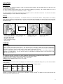
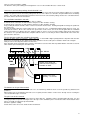
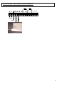
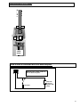
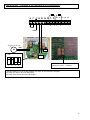
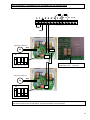
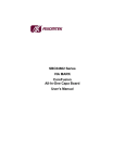
SKYCOM
CONTROL PANEL
INSTALLATION MANUAL
1
Each panel has been tested. A serial number is added on the panel when the test was successful.
The presence of the serial number shows that the panel has been tested.
This manual is valid for panels with serial numbers starting from 16388. The serial number is added
on the PCB :
Version of this manual : 071221, number of pages : 18
The contents of this manual has been checked carefully. Nevertheless, we do not accept any responsibility for mistakes in this manual.
This manual is subject to changes without notice and does not claim completeness.
If you would find any contradictions in this manual, please contact your supplier.
Security
The panel should only be opened by a professional installer. There is a danger of high voltage ! The panel should not be installed in dusty
and/or humid environments and the room temperature has to be between 0°C en 30°C.
Limitations of the system
The panel and the system it is within will possibly not function due to several causes :
Smoke detectors may not function where the smoke can not reach the detector like in chimneys, in walls or in roofs. Smoke detectors may
not sense the fire on an other floor of the building. All types of detectors have their limitations. No type of smoke detector can sense every
kind of fire caused by carelessness and safety hazards such as smoking in bed, violent explosions, escaping gas, improper storage of
inflammable materials, overloaded electrical circuits, children playing with matches or arson.
The risk exists that the panel will not be correctly used due to the panic a fire in a building brings.
The panel and its accessories will not operate without any electrical power. If mains power fails, the panel will work on the batteries, but
only for a limited time.
Detectors will get less sensitive over time and should therefore be part of a maintenance program.
The panel does not provide any security against people or objects getting stuck due to the functioning of the motors. This security has to
be provided externally.
No electronic equipment can give the guarantee it will always function. It is possible that a panel which has been working correctly for a
long period can fail, even after it has just been checked, and could therefore not function in a fire.
Keeping the evacuation routes free of smoke should not only depend on this panel. Installing this panel can only be considered as a
secondary measure and it does not avoid the need of other measures like fire escape ladders outside the building, more evacuation routes,
easy access of the building for the fire brigade, fast warning of the fire brigade by means of a fire detection system. The panel and its
accessories are not a fire detection system as in EN54 and can not be used for this purpose. As described in this manual, the panel can be
coupled with a fire detection system. This system should not be used if there is a risk of loss of people or objects due to the malfunctioning
of this panel. Care has to be taken that there can not be any damage due to rain or wind due to an unwanted opening of the vent.
This panel has to be installed following all the local standards. If the panel and its accessories are being sold in a country outside Belgium,
it is the distributors responsibility to check whether the product fulfills al the necessary requirements and gets the necessary approvals. The
manufacturer of the Skycom panel does not take any responsability on the system if products are connected on the panel that are not sold
by the manufacturer.
2
MOUNTING
Mounting place
The panel has to be mounted so that it is easily accessible by the fire brigade. The fire brigade have to be able to use the
priority control on the panel.
The panel should be mounted where most of the people in the building are passing by. This could for instance be close to
the entrance door through which all inhabitants, visitors,… will pass.
The panel should be clearly visible and mounted on a height of 1,35m or 1,45m above floor level. Fire detectors should be
installed following the current standards and legislation.
Mounting
Do not remove the pcb or the batteries. The batteries have been connected in advance. Many mistakes are made by
connecting the batteries in the wrong way. Be careful so that no dirt from the drilling gets into the panel. (especially metal
parts !) Do not touch the pcb with your hands. The pcb is sensitive for static electricity. Use an earthed bracelet if you have
to remove the pcb.
Put a srew
here.
Use the panel to draw the Put a screw in the left
exact location of the holes hole on the top.
on the wall. Do not drill
through the holes of the
metal ! (metal parts will get
into the panel)
Hang the panel up, on
the top left screw.
Now you can add the
other screws.
CABLING
The cabling has to be done in accordance to the local standards and legislation.
Mains voltage :
Use a separate circuit for the mains voltage. This circuit has to be secured by a double pole fuse and a double pole
switch (to be able to remove the mains). Use the correct section for the cabling (see local standards and legislation).
This panel can only be used in countries where a mains voltage of 230 Volts is present.
There is a minimum distance of 1 meter between all of the cabling to the Skycom panel and existing cabling in the
building to avoid disturbance. The fire detectors have to be installed at a minimum distance of 2m from fluorescent
lights (or other disturbances).
2
The cabling for detectors, call points, key switch, ventilation control must have a minimum section of 0,8 mm .
The maximum cabling distance between panel and the last component is 200m.
2
Cabling for detectors, call points, priority control : 2 wires of 0,8 mm
2
Cabling for extra ventilation control : 3 wires of 0,8 mm .
Use flexible cable !
Fire resistant cable has to be used if the cabling has to remain intact for a certain time during a fire (see also local standards
and legislation).
Section of cabling in relation to the number of motors and distance for the Skylux motors :
section
1motor
2 motors
3 motors
4 motors
2
2 X 1.5mm
88m
44m
30m
22m
2
2 X 2.5 mm
148m
74m
50m
37m
2
2 X 4 mm
240m
120m
80m
60m
2
2 X 6 mm
360m
180m
120m
90m
2
Example : If 2 Skylux motors are connected on a cable with a section of 2.5mm , the distance between panel and the last
motor should not be greater than 74m.
3
Entering the cables
Electrical safety:
The cable for the mains voltage has to be fixed firmly so that it does not come loose by
pulling the cable.
This can be achieved by using a cable tie through the openings in the metal housing. (Put
the cable tie through the holes before hanging the panel on the wall.)
This can also be achieved by using glands.
Remove the isolation of the mains cable as short as possible. The mains cable has to be
double insulated. This can be achieved by adding an insulation sleeve. Be carefull that
the mains cable can not be damaged due to the metal cable entry. If necessary, add a
supplementary protection.
a) Cable coming out of the wall
The panel is designed so that it can be mounted visibly. (for instance in
the entrance of an apartment.)
It is recommended to work with hidden cabling.
For aesthetic reasons the panel is designed compact.
If more than one motor has to be connected it is advised to use an
external box to run the cabling of the motors in parallel.
b) Cable in cable duct next to the panel.
The cable entrance can
be cut through a cable
duct.
Remove the metal
rectangle by means of a
screwdriver. Be careful
not to damage the pcb.
Break the plastic with a
Cut the plastic of the
housing following the lines tool following the line
indicated in the picture.
indicated with an arrow.
c) Cable entry through glands
230V
For entry of the mains
cable : use the gland at
the top, left. Use an
appropriate gland so that
the cable is fixed firmly.
Cut the plastic of the
housing following the
lines indicated in the
picture.
Break the plastic with a
tool following the line
indicated in the picture.
4
CONNECTING THE PANEL
Make a choice out of the connection diagrams in this manual. The choice depends on the components that have to be
connected.
1. Basic installation
2. Panel with call points
3. Panel with fire detectors
4. Panel with call points and fire detectors
5. How to connect a wind - and rain detector
It is recommended to start with the connections as shown in ‘Basic Installation’. Following to this, do the tests described in
chapter ‘TESTING’. After this testing : work step by step. For instance : if you have to connect call points and a ventilation
control, then first connect the call points and test them. Following to this testing : connect the ventilation control and test this
control.
Warning ! The panel is protected against many connection errors. The panel can not be protected
against connecting the mains voltage or the battery voltage on the wrong connectors. Be very
careful when connecting the mains voltage and the batteries !!
Remove the mains voltage and the ‘+’ connection of the battery (remove wire and isolate the wire)
when changing connections in the panel !
Cabling inside the panel :
The cabling in the panel has to be done with care.
The panel is not a connection box for cables ! Work if necessary with an external connection box.
Cut all the wires at the correct length. The panel does not provide enough space to work with wires that are too long.
Bend all the wires to the back of the panel.
The plexi that can be added in the panel can be removed again by pushing the plexi backwards with the metal key. If the
cabling has not been done with the necessary care it will not be possible to push the plexi fully backwards and it will not be
possible to remove the plexi again. (If this happens : remove the sticker at the bottom of the panel and push the plexi
backwards with your finger.)
Connecting the motors :
Up to 2 Skylux motors can be connected on the panel. In normal working state, these motors will take a current in the order
of 300 mA. When the motors start, they take a peak current up to 0,9 A. To allow this start current a slow fuse of 3.15 A is
used in the panel. In the motors there is a pcb that detects peak currents.
When the smoke vent is fully open or closed, the motor will take a higher current and the pcb will automatically switch off the
motor (although there is still 24 volts present on the motor wires).
2
The 2 motors have to be connected in parallel. The connector blocks are suited for a cabling up to 4mm . These connector
blocks are not suited for connecting 2 motors. When it is necessary to connect motors in parallel, use an external
connection box.
5
Functioning of batteries and battery charger
General :
The panel has 2 lead batteries cf 2.1 Ah connected in series. These batteries are continuously charged by the internal
battery charger. The panel will not start up with only the batteries connected. The panel is delivered with the batteries
already connected. Only after the mains voltage has been connected for the first time the panel can continue to work on the
batteries.
The batteries will be damaged when they are discharged to a voltage lower than 21V.
For this reason the panel will switch off when the battery voltage drops under 21V.
The panel will refuse to recharge batteries that are discharged to a voltage lower then 20V or batteries that are polarized
correctly (inversion of – and +).
The batteries are charged to a voltage of maximum 27.6 V.
When a voltage of 24.2 V is reached the battery led will go out to indicate that the battery is charged.
There is a security system build in the panel against charging the batteries with a voltage that is too high (this could only
happen with a defective charger).
Test of the functioning of the charger :
A flashing batt. led (this means a battery voltage between 21V and 24.2V) has to go out within 48 hours of charging
(meaning a battery voltage between 24.2 and 27.6 V) (If the motors have not been used during 48 hours.)
The current needed for the motors is taken of the batteries. It is normal that when the motors have been operated several
times, the batt. led that was out will start flashing.
What happens if there is no mains voltage present for a long time ?
The mains voltage should always be present on the panel. The batteries will slowly be discharged by the panel if the mains
voltage is not present (even without using the motors).
If the smoke vent is being opened with batteries that are discharged too deep, it is possible that the smoke vent can not be
closed immediately. This is because the panel switches off when the voltage drops below 21V.
When this happens you have to connect the mains voltage again to the panel and wait until the batteries are sufficiently
charged.
What to do when the mains voltage has to be removed .
If it is known in advance that the mains voltage will be removed for a longer time (more then 24hr) it is better to remove the
batteries of the system by removing the + wire from the connector block and to isolate the end of the wire.
If you would not disconnect the battery it is possible that the battery would get discharged below 21V and that the panel will
automatically be switched off. Because of self discharging of the battery it is possible that the voltage of the battery would
drop after a longer time to a voltage below 20V. Batteries discharged below 20V are permanently damaged and the panel
will refuse to charge these batteries again.
Connecting a key switch.
The keyswitch has to be connected with 2 wires. The polarity of these wires is not important. (The 2 wires can be inversed.)
If you connect a key switch you have to remove the end of line resistor that is present on the connector block on the
connectors 10 and 11. The end of line resistor is built in the key switch.
When the key switch is in position ‘open’, a resistor of 470 ohms is connected in parallel on the end of line resistor.
When the key switch is in position ‘close’, a resistor of 1200 ohms is put in parallel on the end of line resistor.
6
TESTING
First start up :
Check again that there are no errors in the connections.
Connect the mains voltage.
Danger of high voltage !
On the PCB are spots where 230 volts is present. Remove 230 volts when the PCB can be touched.
In the panel is a build in timer of ± 160 seconds. By pushing ‘open’ this timer will be started. After ± 160 seconds the panel
will indicate that the smoke vent is open. The time needed to open the smoke vent completely depends on the type of
motor. Certain motors will already be open in a time less then 100 seconds.
The closing time will always be 50 seconds longer than the time taken for the smoke vent to open.
If the smoke vent was opened during 80 seconds, the motor will receive voltage during ± 80+50 seconds to close the smoke
vent. This extra timing of ± 50 seconds makes sure that the smoke vent is completely closed.²
In case of first start up : open the smoke vent completely during ± 160 seconds and afterwards close the
smoke vent again during ± 210 seconds. (independent of whether the smoke vent was open, closed or in
between).
This procedure has to be done to be sure that the led indications ‘open’ and ‘close’ correspond to reality.
The panel and all its connected components have to be fully tested. This has to be done in combination with the user
manual.
Testing the fire detectors :
A fire detector can be tested with a smoke detector test spray (or with a piece of paper that, after being extinguished, still
produces smoke). A fire detector should react after ± 6 seconds Following this the alarm led on the panel will light up. The
red led on the fire detector will light up after a detection. The red led remains on until the panel is reset. By resetting the
panel the voltage to the fire detectors is interrupted. This will reset the fire detectors.
Up to 30 detectors can be connected (technically) on the panel (see also local standards, code of practice, legislation). Only
the first detector detecting a fire will light its red led. When more detectors come in the alarm state the leds of the detectors
will be off again, because more leds would increase the current consumption and reduce the autonomy of the panel.
The red alarm led on the panel remains on until the panel is reset.
Testing call points :
A call point can be tested by using the test key that is delivered in the same box of the call point (see also manual of the call
point) Keep in mind that after using the call point, the call point has to be reset again with the key before trying to reset the
panel.
Testing the ventilation control :
For ventilation control normally open pushbuttons have to be used. Keep pressing the buttons until the smoke vent has
reached the desired position. Keep in mind that when a control with a higher priority has been used, the ventilation control
can no longer be used until the panel is reset. The ventilation control can not be used when the alarm led is flashing or
continuously on.
Testing wind – and rain detection :
The rain detector should be installed in such a position that water from rain can easily drip off the detector. An automatic
heater is built into the detector that is activated when the face plate is wet.
The detector also has a trimmer for regulating the wind speed.
If the panel has closed the smoke vent due to rain or high wind speed you have to wait for approximately 2 minutes before
opening again. This delay is built in to avoid sudden winds that would close the vent again.
7
FAULT FINDING
Check the two fuses on the panel. Replace the fuses only with correct, approved fuses !
F1 : T63mA 250V
F2 : T3.15A 250V
In case of problems it is advised to reduce the installation to the basic installation.
Disconnect all the wiring. Connect the 2 end of line resistors on the connectors 8 and 9 and on the connectors 10 and
11. Measure the battery voltage, with the mains voltage disconnected, on the connectors 6 and 7. This voltage should
be between 24 and 27,6 volts. If the voltage is lower, connect the mains voltage and wait until the batteries are charged
again. Connect a voltmeter on the motor connection (connectors 4 and 5). Opening should give the positive battery
voltage, closing should give the negative battery voltage and in normal state you should measure 0 volts.
1 2
N L
3
230V
earth
4
M
5 6 7 8 9 10 11 12 13 14
M +B - B - Z +Z
b
l
u
e
Battery voltage : 21 to 27.6V
Voltage to motor :
Opening : +21 to 27.6V
Closing : -21 to 27.6V
Normal : 0V
The yellow zone led is on
The yellow zone led is continuously on when there is an interruption in the cabling on connectors 8 and 9. Connect the end
of line resistors immediately on the connectors 8 and 9. If the yellow fault led goes out the error is in the cabling.
Causes :
The end of line resistor was not put on the last component or was on the wrong connectors.
There is a bad connection on one or more connecting points.
Be careful when screwing the detector bases on the ceiling with a screwdriver. The screwdriver can give a force that is to
high and this can bend the base when the ceiling is not completely flat. This can result in a bad connection between
detector and base.
The yellow zone led flashes
The yellow zone led will flash on a short circuit on the connectors 8 and 9. Connect the end of line resistor of 3K9
immediately on the connectors 8 and 9. If the fault disappears now, the mistake is clearly in the cabling.
Causes :
The polarization of the fire detectors is important. A wrong polarization of the detectors will cause a short circuit on the
cabling of the zone.
The two wires of the zone cabling can melt together in case of a fire which will cause a short circuit.
The yellow priority led is on
The yellow priority led is continuously on when there is an interruption in the cabling on connectors 10 and 11. Connect the
end of line resistor of 3K9 immediately on the connectors 10 and 11.
Causes :
The end of line resistor was not present. If there is no key switch connected there should be an end of line resistor on
connectors 10 and 11.
There has been a bad connection made.
The yellow priority led flashes
The yellow priority led flashes on a short circuit on connectors 10 and 11. Connect the end of line resistor of 3K9 on the
connectors 10 and 11. If the led does no longer flash, the mistake is clearly in the cabling.
Possible causes :
8
There is a short circuit in the cabling.
The two wires of the prior cabling can melt together in case of a fire and this will cause a short circuit.
I measure a correct battery voltage, but the batt led is on.
The yellow batt. led means that the battery voltage is lower then 21V, but if we measure the battery voltage we see a higher
voltage. The panel measures the battery voltage after the fuse F2. If this fuse is defective, the panel will measure 0V battery
voltage. The motors will not work if the panel does not measure the correct battery voltage because the current that makes
the motors work is taken from the batteries.
The ventilation control does not work
Simulation of ventilation push buttons can be done as follows :
A short circuit on connectors 12 and 14 with a short piece of wire simulates closing.
A short circuit on connectors 13 and 14 with a short piece of wire simulates opening.
Keep pushing the buttons until the smoke vent has reached the desired state. Pushing briefly will not change the position of
the smoke vent.
Check if the alarm led flashes or if the alarm led is on. If this is the case, a control with a higher priority has been used. It is
clear that for instance, when a fire detector has opened the smoke vent it can not be closed again with the ventilation
control. First put the key switch (if present) again in position ‘0’ or press reset to reset the priority control on the panel or the
fire detectors. It is possible that also the call points still have to be reset or that you have to wait until all of the smoke has
gone out of the detectors.
The fire detectors and/or the call points do not work.
Check if the alarm led is on or flashes. If this is the case, a control with a higher priority than the call points and detectors
has been used. First put the key switch (if present) in position ‘0’ and reset the panel so that the alarm led is off again.
Now you can test the call points and the fire detectors.
A fire detection can be simulated on the panel by connection a resistor of 470 ohms in parallel with the end of line resistor of
3K9. Now the panel should get in the alarm state.
End of line : 3K9
1 2 3
N Ph
230V
earth
4
M
b
l
u
e
5 6 7 8 9 10 11 12 13 14
M +B - B - Z +Z
b
r
à
w
n
n
Resistor of 470 ohms (not
delivered with the panel) for
simulation an alarm
Voltage to the motor :
Opening : +21 à 27.6V
The buttons on the panel do not work
Check if the red alarm led flashes. If this is the case, an external key switch has been used. First put the key switch back in
position ‘0’.
When all the leds are off (with the 230V led as an exception) it means that the smoke vent is already closed. Pushing the
‘close’ button will not give a reaction.
The plexi can not be removed.
It is important that the cabling in the panel has been done with care. Probably a cable is pushing against the plexi. It is also
no longer possible to open the housing because the top screw is behind the plexi. Remove the sticker on the bottom of the
panel. Push with your finger the plexi backwards.
Check the again the cabling :
Cut the wires at the correct size, bend the wires backwards.
9
ADDING THE PLEXI IN THE PANEL
The plexi is delivered with a blue protection. First remove this protection ! (The plexi has to be 100%
transparent like a window-glass, this is not the case when the protection is still present.)
Be careful not to break the plexi.
It is important that the plexi is put in the correct way in the panel. On one side of the plexi shallow lines have been milled.
The side of the plexi on which the lines have been milled has to be facing the wall (on which the panel is mounted.
If the plexi has to be replaced, the panel has to be opened to remove the broken pieces
EXPLANATION FOR THE USER :
It is extremely important to explain to the user how the system works by means of the user manual. It is important that the
system is tested by the end user, in the presence of the installer. This will avoid later unnecessary interventions.
REPLACING THE BATTERIES
negative
positive
negative
negativ
e
positive
-
+
-
+
Remove the mains voltage and the red and black wire of the battery (and isolate the end of the wire). Remove the 3 screws
of the pcb. Remove the pcb. Look carefully how the batteries are placed now, so you can do it in the same way with the
new batteries. Remove the battery connectors. Place the new batteries and the connectors as shown in the left picture.
(Connect one negative of the first battery to the positive of the second battery). Put both batteries now in the metal housing.
The space for the batteries and the battery wires is limited because the housing has to be kept compact for aesthetic
reasons. Keep all the wires to the right of the middle metal stud In this way the wires will not be pushed between the
batteries and the pcb. Put the two batteries as close as possible to one another. Fix the batteries firmly with a cable tie or
with tape. Make sure that there is enough space left to the right of the batteries for the user manual (see also user manual).
Be careful when connecting the red and black wire of the battery to the pcb ! Connecting these wires to the wrong
connectors will damage the pcb !
The batteries have to be replaced every three years. During the yearly maintenance the batteries have to be
tested with a battery tester. (It has to be checked that the battery voltage does not drop on adding a load on the
battery).
10
Basic installation : panel without external components
1
N
2
L
3
230V
earth
4 5 6 7 8 9
M M +B - B - Z +Z
b
l
u
e
10 11 12 13 14
b
r
o
w
n
11
Panel with call points
If call points and/or detectors are
used : move the resistor to the last
component.
1
N
2
L
3
If an external key switch is used, remove the resistor.
If no key switch is used, the resistor has to remain on
10 and 11.
4 5 6 7 8 9
M M +B - B - Z +Z
10 11 12 13 14
230V
earth
blue
brown
open
C
l
o
s
e
closed
O
p
e
n
0
If an external
ventilation control is
used, normally open
push buttons should
be used. Any
conventional
material can be
used for this
purpose (Niko,
Ticino,…). To have
the control in more
places : use push
buttons in parallel.
+B -B
1
2
1
2
3
+
-
+
-
4
3
4
The 2 batteries are already
connected when the panel is
delivered. Many connection
errors are made during
connection of the batteries.
For this reason it is advised
not to remove the wiring of
the batteries for mounting
the panel. If the batteries
have to be removed for
maintenance, keep in mind
that the batteries have to be
put in series !
12
Panel with detectors
If an external key switch is used, remove the resistor.
If no key switch is used, the resistor has to remain on
10 and 11.
If call points and/or detectors are
used : move the resistor to the last
component.
1
N
2
L
3
4 5 6 7 8 9 10 11 12 13 14
M M +B - B - Z +Z
230V
earth
blue
brown
a2
a1/
open
closed
C
l
o
s
e
O
p
e
n
0
If an external
ventilation control is
used, normally open
push buttons should
be used. Any
conventional
material can be
used for this
purpose (Niko,
Ticino,…). To have
the control in more
places : use push
buttons in parallel.
b1
a1/
a2
b2
b1
+B -B
+
-
+
The 2 batteries are already
connected when the panel is
delivered. Many connection
errors are made during
connection of the batteries.
For this reason it is advised
not to remove the wiring of
the batteries for mounting
the panel. If the batteries
have to be removed for
maintenance, keep in mind
that the batteries have to be
put in series !
13
Panel with call points and detectors
If call points and/or detectors are
used : move the resistor to the last
component.
1
N
2
L
3
4
M
If an external key switch is used, remove the resistor.
If no key switch is used, the resistor has to remain on
10 and 11.
5 6 7 8 9
M +B - B - Z +Z
10 11 12 13 14
230V
earth
blue
brown
b2
a1/
a2
open
closed
c
l
o
s
e
O
p
e
n
b1
0
a1/
a2
If an external
ventilation control is
used, normally open
push buttons should
be used. Any
conventional
material can be
used for this
purpose (Niko,
Ticino,…). To have
the control in more
places : use push
buttons in parallel.
b2
b1
+B-B
1
3
2
-
+
-
4
2
1
+
3
4
The 2 batteries are already
connected when the panel is
delivered. Many connection
errors are made during
connection of the batteries. For
this reason it is advised not to
remove the wiring of the
batteries for mounting the
panel. If the batteries have to
be removed for maintenance,
keep in mind that the batteries
have to be put in series !
14
How to add a wind and rain detector.
If an external key switch is used, remove the resistor.
If no key switch is used, the resistor has to remain on
10 and 11.
If call points and/or detectors are
used : move the resistor to the last
component.
1
N
2
L
3
4 5 6 7 8 9
M M +B - B - Z +Z
10 11 12 13 14
230V
earth
blue
brown
b2
a1
/
a2
open
close
b1
c
l
o
s
e
O
p
e
n
0
a1/
a2
b1
b2
+B -B
1 2 3 4 5 6 7 8 9
230V
-
+
+
The 2 batteries are already
connected when the panel is
delivered. Many connection
errors are made during
connection of the batteries.
For this reason it is advised
not to remove the wiring of
the batteries for mounting
the panel. If the batteries
have to be removed for
maintenance, keep in mind
that the batteries have to be
put in series !
-
1
3
4
2
1
2
b
l
u
e
W
h
I
t
e
Y
e
l
l
o
w
On this unit you have a
normally open contact on 8
and 9, Connect this contact
in parallel with the ‘close’
ventilation button.
3
4
15
How to connect a JOFO motor.
B
r
o
w
n
B
L
u
e
4
6
8
1
JOFO
motor
How to make a connection with a fire detection panel.
8
9
Normally open output contact of
the fire detection panel.
470 ohms
3900 ohm
(delivered
together with
panel)
16
How to connect 1 SA power or RA 160 motor on the Skycom panel
1
N
2
L
3
4
M
5 6 7 8 9 10 11 12 13 14
M +B - B - Z +Z
230V
earth
SA power or RA 160
blue
M
34
brown
ON
1
12
2
3
4
Fuse F2 on the Skycom panel has to be
replaced by a fuse : “T 8A slow”
If the dip switches are in the 5A limit condition one motor can be connected to the panel.
Dip switch one and two are in the ON position.
Dip switch three and four are in the OFF position.
17
How to connect 2 SA power or RA 160 motors on the Skycom panel
1
N
2
L
3
4
M
5 6 7 8 9 10 11 12 13 14
M +B - B - Z +Z
230V
earth
SA power or RA 160
blue
M
34
brown
ON
1
12
2
3
Fuse F2 on the Skycom panel has to be
replaced by a fuse : “T 8A slow”
4
SA power or RA 160
blue
M
brown
12
ON
1
2
3
4
It is extremely important to put the dip switches in the 3 Amp limit condition when two motors are connected !
Dip switch one has to be in the ON position, the other dip switches in the OFF position.
18