1
APPLICATION FOR LOW VOLTAGE DIRECTIVE
On Behalf of
Shenzhen New Huayi Instrument Co., Ltd
DIGITAL MULTIMETER
Model no.: M300
Prepared for :
Shenzhen New Huayi Instrument Co., Ltd
Address:
F3, Block 2, Instrument World Industrial Park, Guiyue Road,
Longhua New District, Shenzhen City
Prepared By :
Shenzhen Certification Technology Service Co., Ltd.
Address:
2F, Building B, East Area of Nanchang Second Industrial Zone,
Gushu 2nd Road, Bao'an District, Shenzhen 518126, P.R. China
Date of Test:
Date of Report:
Report Number:
Version number:
March 01-03, 2014
March 03-04, 2014
CSTS140227045
REV0
TEST REPORT
IEC 61010-1 / EN 61010-1
Safety requirements for electrical equipment for measurement,
control, and laboratory use
Part 1: General requirements
Report Reference No..................... :
CSTS140227045
Tested by (name + signature) .........:
Jonson Cai
Approved by (name + signature) ......:
Kaiden Guo
Date of issue.....................................:
March 04, 2014
Testing Laboratory ........................ :
Shenzhen Certification Technology Service Co., Ltd.
Address ............................................:
2F, Building B, East Area of Nanchang Second Industrial Zone,
Gushu 2nd Road, Bao'an District, Shenzhen 518126, P.R. China
Testing location/procedure ...............:
TL [√ ]
Address ............................................:
Same as above
Applicant’s name............................:
Shenzhen New Huayi Instrument Co., Ltd
Address ............................................:
F3, Block 2, Instrument World Industrial Park, Guiyue Road,
Longhua New District, Shenzhen City
......................................................
......................................................
CBTL [ ]
SMT [ ]
TMP [ ]
Test specification:
Standard ...........................................:
EN 61010-1: 2010
EN 61010-2-031:2002 + A1:2008
Test procedure .................................:
LVD Approval
Non-standard test method................:
N.A.
Test Report Form No......................:
IEC/EN 61010_1F
TRF Originator..................................:
VDE Testing and Certification Institute
Master TRF.......................................:
2011-03
Copyright © 2011 Worldwide System for Conformity Testing and Certification of Electrotechnical
Equipment and Components (IECEE), Geneva, Switzerland. All rights reserved.
This publication may be reproduced in whole or in part for non-commercial purposes as long as the IECEE is acknowledged as
copyright owner and source of the material. IECEE takes no responsibility for and will not assume liability for damages resulting from
the reader's interpretation of the reproduced material due to its placement and context.
Test item description .....................:
DIGITAL MULTIMETER
Model/Type reference ........................:
M300
Manufacturer.......................................:
Shenzhen New Huayi Instrument Co., Ltd
Address...............................................:
F3, Block 2, Instrument World Industrial Park, Guiyue Road,
Longhua New District, Shenzhen City
Trademark……………………………..:
HYELEC
Rating(s) ...........................................:
1×12Vdc L1028 battery; 600V CATII; Class II
Page 2 of 92
Report No. CSTS140227045
Test item particulars ..................................................:
Type of item tested ....................................................... : Measuring equipment
Description of equipment function................................: Measure for voltage, current, resistance, diode.
Installation/overvoltage category..................................: 600V CATII
Pollution degree............................................................: Pollution degree 2
Environmental rating..................................................: Temperature: 0 ~ +40°C
Equipment mobility ....................................................: Portable equipment
Connection to mains supply ......................................: None
Operating conditions..................................................: Continuous
Marked degree of protection to IEC 60529 ...............: IP20
Accessories and detachable parts included in the
N/A
evaluation ..................................................................:
Options ......................................................................: N/A
Test case verdicts:
Test case does not apply to the test object ................. : N(/A)
Test object does meet the requirement ....................... : P(Pass)
Test object does not meet the requirement ................. : F(Fail)
Testing ......................................................................... :
Date of receipt of test item ........................................... : March 01, 2014
Date (s) of performance of tests................................... : March 01-03, 2014
General remarks:
This report shall not be reproduced, except in full, without the written approval of the issuing testing laboratory.
The test results presented in this report relate only to the item(s) tested.
"(see remark #)" refers to a remark appended to the report.
"(see Annex #)" refers to an annex appended to the report.
"(see Form A.#)" refers to a table appended to the report.
Throughout this report a comma (point) is used as the decimal separator.
TRF No. IEC61010_1F
TRF originator: VDE
Page 3 of 92
Report No. CSTS140227045
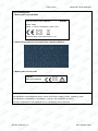
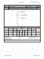
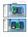
Copy of marking plate:
1) Marking label for model M300
DIGITAL DIGITAL MULTIMETER
HYELEC
Model : M300
Rated : 1×12Vdc L1028 battery; 600V CATII
Shenzhen New Huayi Instrument Co., Ltd
2) Below warning statement and symbol were marked on appliance
3) Marking label for test probe
HYELEC
600V CATII / MAX 2A
Summary of test results (information/comments):
- The equipment is a measurement device, which can measure voltage, current, resistance, diode.
- The equipment is powered by L1028 battery ( 1 pieces), with total plastic enclosure.
- The max. temperature of the appliance is 40 ºC, declared by the manufacturer.
TRF No. IEC61010_1F
TRF originator: VDE
Page 4 of 92
Report No. CSTS140227045
IEC/EN 61010-1
Clause
Requirement + Test
Result - Remark
Verdict
P
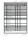
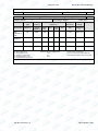
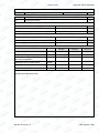
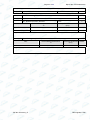
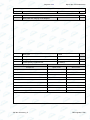
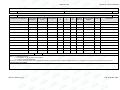
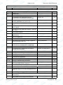
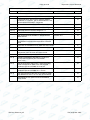
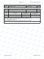
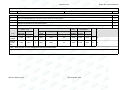
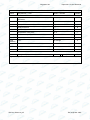
TABLE : 1 - Documents attached to this report
Document No.
Document description
Page Numbers
Appendix 2
Photo documentation
91-92
P
TABLE: 2 - Test equipment list
Item
Manufacturer
-
Equipment
-
Model No.
Calibration date
1
Comments
Due
Last
*Note: Appendix 1 (Page 89-90)
1) or interval between calibrations.
P
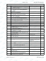
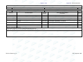
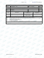
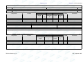
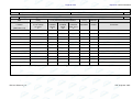
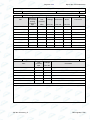
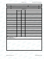
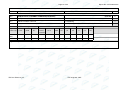
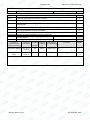
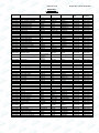
TABLE: 3 – List of components and circuits relied on for safety
Unique component
reference or location
Manufacturer
Part number
Evidence
of acceptance
RATING
(NOTE 1)
(NOTE 2)
(including drawing reference
if required)
(NOTE 3)
Enclosure
(Various)
(Various)
Min thickness 1.5 mm,
V-0, 85℃
UL
PCB
(Various)
(Various)
V-0, 130°C
UL
Fuse
(Various)
(Various)
100mA, 250V
Internal wire
(Various)
(Various)
80°C, 300V, VW-1,
30AWG or better
Hand-held probe
Shenzhen New Huayi
Instrument Co., Ltd
(Various)
600V CATII/MAX 2A
- plastic enclosure
(Various)
(Various)
V-0, 85℃
UL
- lead wire
(Various)
(Various)
24 AWG or better, 80
℃, 4000V, PVC
insulation
UL
Battery
--
L1028
DC 12V
--
VDE
UL
Test with
appliance
NOTE 1 - List all manufacturers concerned.
NOTE 2 - Electrical, mechanical, flammability, etc.
NOTE 3 - Licence number, file number or other documentary evidence of acceptance
TRF No. IEC61010_1F
TRF originator: VDE
Page 5 of 92
Report No. CSTS140227045
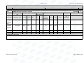
IEC/EN 61010-1
Clause
Requirement + Test
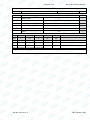
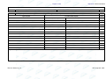
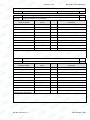
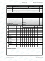
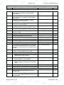
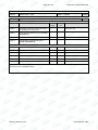
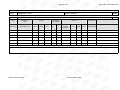
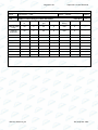
4.4
Testing in SINGLE FAULT CONDITIONS
4.4.1
Fault tests
4.4.2
Application of SINGLE FAULT CONDITIONS
P
4.4.2.1
FAULT CONDITIONS SHALL INCLUDE THOSE SPECIFIED IN (see Form A.1 and A.2)
4.4.2.2 TO 4.4.2.14
—
4.4.2.2
PROTECTIVE IMPEDANCE
N
4.4.2.3
PROTECTIVE CONDUCTOR
N
4.4.2.4
Equipment or parts for short-term or intermittent
operation
N
4.4.2.5
Motors
N
4.4.2.6
Capacitors
4.4.2.7
MAINS transformers
N
4.4.2.7.2
Short circuit
N
4.4.2.7.3
Overload
N
4.4.2.8
Outputs
P
4.4.2.9
Equipment for more than one supply
N
4.4.2.10
Cooling
N
4.4.2.11
Heating devices
N
4.4.2.12
Insulation between circuits and parts
P
4.4.2.13
Interlocks
N
4.4.2.14
Voltage selectors
N
4.4.3
Duration of tests
(see Form A.1 and A.2)
P
4.4.4
Conformity after application of fault conditions
(see Form A.1; A.2; A.8, A.14)
P
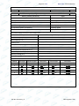
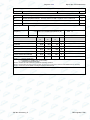
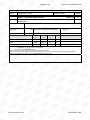
5
MARKING AND DOCUMENTATION
P
5.1.1
General
P
Required equipment markings are:
—
visible:
P
From the exterior; or
P
After removing a cover; or
N
Opening a door
N
After removal from a rack or panel
N
Not put on parts which can be removed by an
operator
P
Letter symbols (IEC 60027) used
P
Graphic symbols (IEC 61010-1: Table 1) used
5.1.2
Result - Remark
Verdict
P
(see Form A.1 and A.2)
No such capacitor
Refer to rating label
P
N
P
Identification
—
Equipment is identified by:
P
TRF No. IEC61010_1F
TRF originator: VDE
Page 6 of 92
Report No. CSTS140227045
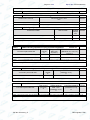
IEC/EN 61010-1
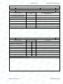
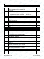
Clause
5.1.3
Requirement + Test
Result - Remark
Verdict
a) Manufacturer’s or supplier’s name or trademark See page 1
P
b) Model number, name or other means
See page 1
P
Manufacturing location identified
Only one factory
N
MAINS supply
Powered by battery only
N
Equipment is marked as follows:
N
a) Nature of supply:
N
1) a.c. RATED MAINS frequency or range of
frequencies.................................................. :
N
2) d.c. with symbol 1
N
RATED supply
voltage(s) or range..................... :
N
c) Max. RATED power (W or VA) or input current ... :
N
The marked value not less than 90 % of the
maximum value
N
If more than one voltage range:
N
Separate values marked; or
N
b)
Values differ by less than 20 %
d)
OPERATOR-set
for different RATED supply
(see Form A.3)
N
N
voltages:
Indicates the equipment set voltage
N
Portable equipment indication is visible from the
exterior
N
Changing the setting changes the indication
N
e) Accessory MAINS socket-outlets accepting
standard MAINS plugs are marked:
5.1.4
N
With the voltage if it is different from the MAINS
supply voltage ................................................... :
N
For use only with specific equipment
N
If not marked for specific equipment it is marked
with:
N
The maximum rated current or power; or
N
Symbol 14 with full details in the documentation
N
Fuses
P
Operator replaceable fuse marking
(see also 5.4.5) ........................................................ :
N
5.1.5
TERMINALS, connections and operating devices
P
5.1.5.1
General
P
Where necessary for safety, indication of purpose
of TERMINALS, connectors, controls and indicators
marked
P
If insufficient space, symbol 14 used
P
Push-buttons and actuators of emergency stop
devices and indicators:
N
TRF No. IEC61010_1F
TRF originator: VDE
Page 7 of 92
Report No. CSTS140227045
IEC/EN 61010-1
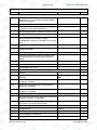
Clause
Requirement + Test
Result - Remark
used only to indicate a warning of danger or
N
the need for urgent action
N
coloured red
N
coded as specified in IEC 60073
N
Supplementary means of coding provided, if
meaning of colour relates (see IEC 60073):
5.1.5.2
5.1.7
N
to safety of persons; or
N
safety of the environment
N
TERMINALS
P
MAINS supply TERMINAL identified
N
Other TERMINAL marking:
P
(symbol 5 used)
N
a)
FUNCTIONAL EARTH TERMINALS
b)
PROTECTIVE CONDUCTOR TERMINALS:
N
Symbol 6 is placed close to or on the TERMINAL;
or
N
Part of appliance inlet
N
of control circuits (symbol 7 used)
N
d) HAZARDOUS LIVE TERMINALS supplied from the
interior
P
c)
5.1.6
Verdict
TERMINALS
Standard MAINS socket outlet; or
N
RATINGS marked; or
P
Symbol 14 used
P
Switches and circuit breakers
P
If disconnecting device, off position clearly marked
P
If push-button used as power supply switch:
N
Symbol 9 and 15 used for on-position
N
Symbol 10 and 16 used for off-position
N
Pair of symbols 9, 15 and 10, 16 close together
N
Equipment protected by DOUBLE INSULATION or
P
REINFORCED INSULATION
5.1.8
5.2
Protected throughout (symbol 11 used)
P
Only partially protected (symbol 11 not used)
N
Field-wiring TERMINAL boxes
N
If TERMINAL or ENCLOSURE exceeds 60 °C:
N
Cable temperature RATING marked ....................... :
N
Marking visible before and during connection or
beside TERMINAL
N
Warning markings
P
Visible when ready for NORMAL USE
P
Are near or on applicable parts
P
TRF No. IEC61010_1F
TRF originator: VDE
Page 8 of 92
Report No. CSTS140227045
IEC/EN 61010-1
Clause
5.3
Requirement + Test
Result - Remark
Verdict
Symbols and text correct dimensions and colour:
—
a) symbols min 2,75 mm and text 1,5 mm high
and contrasting in colour with background
P
b) symbols and text moulded, stamped or
engraved in material min. 2,0 mm high and
P
0.5 mm depth or raised if not contrasting in
colour
P
If necessary marked with symbol 14
P
Statement to isolate or disconnect if access by
using a tool to HAZARDOUS LIVE parts is permitted
P
Durability of markings
P
The required markings remain clear and legible in
(see Form A.4)
P
NORMAL USE
5.4
Documentation
P
5.4.1
General
P
Equipment is accompanied by documentation for
Provided in user’s manual.
safety purposes for OPERATOR or RESPONSIBLE BODY
P
Safety documentation for service personnel
authorized by the manufacturer
P
Documentation necessary for safe operation is
provided in printed media or
P
in electronic media if available at any time
N
Documentation includes:
—
a) intended use
P
b) technical specification
P
c) name and address of manufacturer or supplier
P
d) Information specified in 5.4.2 to 5.4.6
P
e) information to mitigate residual RISK
(see also subclause 17)
P
f)
accessories for safe operation of the equipment
specified
P
g) guidance provided to check correct function of
the equipment, if incorrect reading may cause a
HAZARD from harmful or corrosive substances of
HAZARDOUS live parts
P
h) instructions for lifting and carrying
N
Warning statements and a clear explanation of
warning symbols:
—
Provided in the documentation; or
P
Information is marked on the equipment
P
Equipment ratings
P
Documentation includes:
P
a) Supply voltage or voltage range .......................: Powered by battery
P
5.4.2
TRF No. IEC61010_1F
TRF originator: VDE
Page 9 of 92
Report No. CSTS140227045
IEC/EN 61010-1
Clause
Requirement + Test
N
Power or current rating................................... :
N
b) Description of all input and output connections
in accordance to 6.6.1 a)
P
N
RATING of insulation of external circuits in
accordance to 6.6.1 b)
d) Statement of the range of environmental
conditions (see 1.4)
Environmental indicated
P
e) Degree of protection (IEC 60529)
IP20
N
f)
if impact rating less than 5 J:
N
IK code in accordance to IEC 62262 marked or
N
symbol 14 of table 1 marked, with
N
RATED
5.4.4
Verdict
Frequency or frequency range....................... :
c)
5.4.3
Result - Remark
energy level and test method stated
Equipment installation
N
Portable device, not need
installation
N
Documentation includes instructions for:
N
a) assembly, location and mounting requirements
N
b) protective earthing
N
c) connections to supply
N
d) permanently connected equipment:
N
1) Supply wiring requirements
N
2) If external switch or circuit-breaker,
requirements and location recommendation
N
e) ventilation requirements
N
f)
N
special services (e. g. air, cooling liquid)
g) Instructions relating to sound level
N
aa) for permanently connected measuring circuit
TERMINALS RATED for MEASUREMENT
CATEGORIES II, III or IV
N
bb) for permanently connected measuring circuit
TERMINALS that are not RATED for
MEASUREMENT CATEGORIES II, III or IV
N
Equipment operation
See below.
P
Instructions for use include:
P
a) identification and description of operating
controls
P
b) positioning for disconnection
N
c) instructions for interconnection
N
d) specification of intermittent operation limits
N
e) explanation of symbols used
Symbols have explanation in
user manual.
P
f)
Battery
P
replacement of consumable materials
TRF No. IEC61010_1F
TRF originator: VDE
Page 10 of 92
Report No. CSTS140227045
IEC/EN 61010-1
Clause
Requirement + Test
Result - Remark
Verdict
g) cleaning and decontamination
Use soft dry cloth without any
solvents or water.
P
N
h) Listing of any poisonous or injurious gases and
quantities
reduction procedures relating to flammable
liquids (see 9.5)
N
reduction procedures relating burn from
surfaces permitted to exceed limits of 10.1
N
i)
RISK
j)
RISK
Additional precautions for IEC 60950 conforming
equipment in regard to moistures and liquids
N
A statement about protection impairment if used in
a manner not specified by the manufacturer
P
Equipment maintenance
P
Instructions for RESPONSIBLE BODY include:
—
Instructions sufficient in detail permitting safe
maintenance and inspection and continued safety:
P
Instruction against the use of detachable MAINS
supply cord with inadequate rating
N
Specific battery type of user replaceable batteries
P
Any manufacturer specified parts
N
Rating and characteristics of fuses
N
Instructions include following subjects permitting safe Service by qualified person of
servicing and continued safety:
manufacturer only. The
information is not provided in
user instruction
N
a) product specific RISKS may affect service
personnel
N
b) protective measures for these RISKS
N
c) verification of the safe state after repair
N
Integration into systems or effects resulting from
special conditions
N
Aspects described in documentation
N
6
PROTECTION AGAINST ELECTRIC SHOCK
P
6.1
General
6.1.1
Requirements
—
Protection against electric shock maintained in
and SINGLE FAULT CONDITION
P
5.4.5
5.4.6
(see Form A.5)
P
NORMAL CONDITION
ACCESSIBLE
parts not HAZARDOUS LIVE
Voltage, current, charge or energy below the limits in
and in SINGLE FAULT CONDITION
between:
All accessible parts are not
hazards live
P
—
NORMAL CONDITION
ACCESSIBLE
TRF No. IEC61010_1F
parts and earth
P
TRF originator: VDE
Page 11 of 92
Report No. CSTS140227045
IEC/EN 61010-1
Clause
6.1.2
Requirement + Test
Result - Remark
Verdict
two ACCESSIBLE parts on same piece of the
equipment within a distance of 1,8 m
N
Conformity is checked by the determination of 6.2
and 6.3 followed by the tests of 6.4 to 6.11
P
Exceptions
N
Following HAZARDOUS LIVE parts may be accessible to
an OPERATOR:
N
a) parts of lamps and lamp sockets after lamp
removal
N
b) parts to be replaced by operator only by the use
of tool and warning marking
N
Those parts not HAZARDOUS LIVE 10 s after
interruption of supply
(see Forms A.6 )
N
Capacitance test if charge is received from internal
capacitor
(see Forms A.6 and A.7)
N
6.2
Determination of accessible parts
(see Form A.6)
P
6.2.1
General
P
Unless obviously determination of accessible parts
as specified in 6.2.2 to 6.2.4
P
Examination
P
- with jointed test finger (as specified B.2)
P
- with rigid test finger (as specified B.1) and a force of
10 N
P
Openings above parts that are HAZARDOUS LIVE
N
- test pin with length of 100 mm and 4 mm in
diameter applied
N
Openings for pre-set controls
N
- test pin with length of 100 mm and 4 mm in
diameter applied
N
6.3
Limit values for ACCESSIBLE parts
P
6.3.1
Levels in NORMAL CONDITION
6.2.2
6.2.3
6.2.4
(see Form A.7)
P
a) Voltage limits less than 33 V r.m.s. and 46,7 V
peak or 70 V d.c.
P
for wet locations voltage limits less than 16 V
r.m.s. and 22,6 V peak or 35 V d.c.
N
Voltages are not HAZARDOUS LIVE the levels of:
—
b) Current less than 0,5 mA r.m.s. for sinusoidal,
0,7 mA peak non sinusoidal or mixed
frequencies or 2 mA d.c. when measured with
measuring circuit A.1 or A.2 if less than 100 Hz
P
for wet locations measuring circuit A.4 used
N
or
N
c) Levels of capacitive charge or energy less:
N
TRF No. IEC61010_1F
TRF originator: VDE
Page 12 of 92
Report No. CSTS140227045
IEC/EN 61010-1
Clause
6.3.2
Requirement + Test
Result - Remark
Verdict
1) 45 µC for voltages up to 15 kV peak or d.c. or
line A of Figure 3
N
2) 350 mJ stored energy for voltages above 15
kV peak or d.c.
N
Levels in SINGLE FAULT CONDITION
(see Form A.7)
P
a) Voltage limits less than 33 V r.m.s. and 46,7 V
peak or 70 V d.c.
P
for wet locations voltage limits less than 16 V
r.m.s. and 22,6 V peak or 35 V d.c.
N
Voltages are not HAZARDOUS LIVE the levels of:
—
b) Current less than 0,5 mA r.m.s. for sinusoidal,
0,7 mA peak non sinusoidal or mixed
frequencies or 2 mA d.c. when measured with
measuring circuit A.1 or A.2 if less than 100 Hz
P
for wet locations measuring circuit A.4 used
N
or
N
c) Levels of capacitive charge or energy less:
N
1) 45 µC for voltages up to 15 kV peak or d.c. or
line A of Figure 3
N
2) 350 mJ stored energy for voltages above 15
kV peak or d.c.
N
6.4
Primary means of protection
P
6.4.1
ACCESSIBLE parts prevented from being HAZARDOUS
LIVE by one or more of following means:
P
a)
ENCLOSURES or PROTECTIVE BARRIERS
b)
BASIC INSULATION
P
(see 6.4.2)
P
(see 6.4.3)
N
c) Impedance (see 6.4.4)
6.4.2
ENCLOSURES or PROTECTIVE BARRIERS
(see Form A.13)
P
- meet rigidity requirements of 8.1
P
- meet requirements for BASIC INSULATION, if
protection is provided by insulation
P
- meet requirements of 6.7 for CREEPAGE and
CLEARANCES between ACCESSIBLE parts and
HAZARDOUS live parts, if protection is provided
P
by
limited access
6.4.3
BASIC INSULATION
(see Form A.13)
- meet CLEARANCE, CREEPAGE DISTANCE and solid
insulation requirements of 6.7
6.4.4
Impedance
P
(see Form A.12)
Impedance used as primary means of protection
meets all of following requirements:
a) limits current or voltage to level of 6.3.2
b)
RATED for maximum WORKING VOLTAGE and the
amount of power it will dissipate
TRF No. IEC61010_1F
P
N
—
(see Form A.7)
N
N
TRF originator: VDE
Page 13 of 92
Report No. CSTS140227045
IEC/EN 61010-1
Clause
Requirement + Test
c)
CLEARANCE, CREEPAGE DISTANCE between
terminations of the impedance meet
requirements of BASIC INSULATION of 6.7
Result - Remark
Verdict
(see Form A.13)
N
6.5
Additional means of protection in case of SINGLE FAULT CONDITION
P
6.5.1
Accessible parts are prevented from becoming
hazardous live by the primary means of protection
and supplemented by one of:
P
(see 6.5.2)
a)
PROTECTIVE BONDING
b)
SUPPLEMENTARY INSULATION
(see 6.5.3)
N
P
c) automatic disconnection of the supply (see 6.5.5)
N
d) current- or voltage-limiting device (see 6.5.6)
P
Alternatively one of the single means of protection is
used:
P
e)
REINFORCED INSULATION
(see 6.5.3)
P
f)
PROTECTIVE IMPEDANCE
(see 6.5.4)
N
6.5.2
Protective bonding
N
6.5.2.1
Accessible conductive parts, may become
harzardous live in single fault condition:
N
Bonded to the protective conductor terminal; or
N
Separated by conductive screen or barrier bonded to
protective conductor terminal
N
CONFORMITY IS CHECKED AS SPECIFIED IN 6.5.2.2 TO
6.5.2.6 AND 6.5.2.101.
N
Integrity of protective bonding
N
6.5.2.2
a)
PROTECTIVE BONDING consists of directly
connected structural parts or discrete conductors
or both; and withstands thermal and dynamic
stresses
N
b) Soldered connections:
N
Independently secured against loosening
N
Not used for other purposes
N
c) Screw connections are secured
N
d)
PROTECTIVE BONDING not
interrupted; or
exempted as removable part carries MAINS SUPPLY
N
N
INPUT connection
e) Any moveable PROTECTIVE BONDING connection
specifically designed, and meets 6.5.2.4
N
f)
N
No external metal braid of cables used
(not regarded as PROTECTIVE BONDING)
g) IF MAINS SUPPLY PASSES THROUGH:
N
Means provided for passing protective conductor;
N
Impedance meets 6.5.2.4
N
TRF No. IEC61010_1F
TRF originator: VDE
Page 14 of 92
Report No. CSTS140227045
IEC/EN 61010-1
Clause
Requirement + Test
Result - Remark
N
h) Protective conductors bare or insulated,
if insulated, green/yellow
Exceptions:
N
1) earthing braids;
N
2) internal protective conductors etc.;
N
Green/yellow not used for other purposes
N
TERMINAL suitable for connection
CONDUCTOR, and meets 6.5.2.3
6.5.2.3
Verdict
N
of a PROTECTIVE
PROTECTIVE CONDUCTOR TERMINAL
N
a) Contact surfaces are metal
N
b) Appliance inlet used
N
c) For rewirable cords and PERMANENTLY
CONNECTED EQUIPMENT, PROTECTIVE CONDUCTOR
TERMINAL is close to MAINS supply TERMINALS
N
d) If no MAINS supply is required, any PROTECTIVE
CONDUCTOR TERMINAL:
N
Is near terminals of circuit for which protective
earthing is necessary
N
External if other terminals external
N
e) Equivalent current-carrying capacity to MAINS
supply TERMINALS
(see Form A.9)
N
If plug-in, makes first and breaks last
N
g) If also used for other bonding purposes,
protective conductor:
N
f)
Applied first;
N
Secured independently;
N
Unlikely to be removed by servicing
N
N
h) PROTECTIVE CONDUCTOR of measuring circuit:
N
1) Current RATING equivalent to measuring
circuit TERMINAL;
2)
i)
PROTECTIVE BONDING:
N
Not interrupted; or
N
FUNCTIONAL EARTH TERMINALS allow
N
independent
connection
j)
N
If a binding screw used for PROTECTIVE
CONDUCTOR TERMINAL:
Suitable size for bond wire
N
Not smaller than M 4 (No. 6)
N
At least 3 turns of screw engaged
N
Passes tightening torque test
k) Contact pressure not capable being reduced by
deformation of materials
TRF No. IEC61010_1F
(see Form A.9)
N
N
TRF originator: VDE
Page 15 of 92
Report No. CSTS140227045
IEC/EN 61010-1
Clause
Requirement + Test
Result - Remark
Verdict
6.5.2.4
Impedance of PROTECTIVE BONDING of plugconnected equipment
(see Form A.10)
N
Impedance between PROTECTIVE CONDUCTOR
TERMINAL and each ACCESSIBLE part where
PROTECTIVE BONDING is specified, is:
6.5.2.5
—
less than 0,1 Ohm; or
N
less than 0,2 Ohm if equipment is provided with
non detachable cord
N
Bonding impedance of PERMANENTLY CONNECTED
(see Form A.10)
N
(see Form A.11)
N
EQUIPMENT
6.5.2.6
Transformer PROTECTIVE BONDING screen
Transformer provided with screen for protective
bonding:
6.5.3
6.5.4
N
screen bonding consists of directly connected
structural parts or discrete conductors or both;
and withstands thermal and dynamic stresses
(see 6.5.2.2 a )
N
screen bonding with soldered connection (see
6.5.2.2 b ) is:
N
- Independently secured against loosening
N
- Not used for other purposes
N
SUPPLEMENTARY and REINFORCED INSULATION
P
- meet CLEARANCE, CREEPAGE DISTANCE and solid
insulation requirements of 6.7
P
PROTECTIVE IMPEDANCE
(see Form A.12)
N
N
Limits current or voltage to level of 6.3.1 in NORMAL
and to level of 6.3.2 in SINGLE FAULT CONDITION
CLEARANCE, CREEPAGE DISTANCE
between
terminations of the impedance meet requirements of
DOUBLE or REINFORCED INSULATION of 6.7
(see Form A.13)
N
The protective impedance consists of one or more of (see Table 3 and Form A.12)
the following:
—
a) appropriate single component suitable for safety
and reliability for protection, it is:
N
1) RATED twice the maximum WORKING VOLTAGE
N
2) resistor RATED for twice the power dissipation
for maximum WORKING VOLTAGE
N
b) combination of components
N
Single electronic device not used as PROTECTIVE
N
IMPEDANCE
6.5.5
Automatic disconnection of the supply
N
a)
RATED to disconnect the load within time
specified in Figure 2
N
b)
RATED for the maximum load conditions of the
equipment
N
TRF No. IEC61010_1F
TRF originator: VDE
Page 16 of 92
Report No. CSTS140227045
IEC/EN 61010-1
Clause
Requirement + Test
Result - Remark
6.5.6
Current- or voltage limiting devices
P
Device complies with all of:
P
a)
RATED to limit the current or voltage to the level
of 6.3.2
b)
RATED
c)
Verdict
P
P
for the maximum working voltage; and
RATED for the maximum operational current if
applicable
P
CLEARANCE, CREEPAGE DISTANCE between
terminations of the impedance meet
requirements of SUPPLEMENTARY INSULATION of
6.7
P
6.6
Connections to external circuits
P
6.6.1
Connections do not cause ACCESSIBLE parts of the
following to become HAZARDOUS LIVE in NORMAL
CONDITION or SINGLE FAULT CONDITION:
P
P
- the equipment
P
Protection achieved by separation of circuits; or
N
short circuit of separation does not cause a HAZARD
P
Instructions or markings for each terminal include:
P
a)
6.6.2
- the external circuits
RATED conditions
b) Required RATING of external circuit INSULATION
P
TERMINALS for external circuits
P
TERMINALS which receive a charge from an internal
capacitor are not HAZARDOUS LIVE after 10 s of
interrupting supply connection
6.6.3
6.6.4
P
for TERMINAL
(see Form A.7)
P
Circuits with terminals which are HAZARDOUS LIVE
P
These circuits are:
P
Not connected to ACCESSIBLE conductive parts; or
P
Connected to ACCESSIBLE conductive parts, but are
not MAINS circuits and have one TERMINAL contact at
earth potential
N
No ACCESSIBLE conductive parts are HAZARDOUS LIVE
P
ACCESSIBLE terminals for stranded conductors
N
No RISK of accidental contact because:
N
Located or shielded
N
Self-evident or marked whether or not connected
to ACCESSIBLE conductive parts
N
ACCESSIBLE TERMINALS will not work loose
6.7
Insulation requirements
6.7.1
The nature of insulation
TRF No. IEC61010_1F
N
(see Form A.5)
P
P
TRF originator: VDE
Page 17 of 92
Report No. CSTS140227045
IEC/EN 61010-1
Clause
Requirement + Test
6.7.1.1
Insulation between ACCESSIBLE parts or between
separate circuits consist of CLEARANCES, CREEPAGE
DISTANCES and solid insulation if provided as
protection against a HAZARD
P
6.7.1.2
CLEARANCES
P
Required CLEARANCES reflecting factors of 6.7.1.1
6.7.1.3
6.7.1.5
6.7.2
(see Form A.5)
Verdict
P
Equipment rated for operating altitude greater than
2000 m correction factor of Table 3 of 61010-1
applied
N
CREEPAGE DISTANCES
P
Required CLEARANCES reflecting factors of 6.7.1.1
6.7.1.4
Result - Remark
(see Form A.5)
P
CTI material group reflected by requirements
P
CTI test performed
N
Solid insulation
P
Required CLEARANCES reflecting factors of 6.7.1.1
(see Form A.5)
P
Requirements for insulation according to type of
circuit
Refer to annex K of
EN 61010-1
P
a) 6.7.2 MAINS circuits of OVERVOLTAGE CATEGORY II
up to nominal supply voltage of 300 V
N
b) 6.7.3 Secondary circuits separated from circuits
defined in a) by transformer
N
c) K.1 MAINS circuits of OVERVOLTAGE CATEGORY III
and IV or OVERVOLTAGE CATEGORY II over 300 V
P
d) K.2 Secondary circuits separated from circuits
defined in a) by transformer
N
e) K.3 Circuits having one or more of:
N
1) maximum TRANSIENT OVERVOLTAGE is limited to
known level below the level of MAINS CIRCUIT
N
2) maximum TRANSIENT OVERVOLTAGE above the
level of MAINS CIRCUIT
N
3) WORKING VOLTAGE is the sum of more than
one circuit or a mixed voltage
N
4) WORKING VOLTAGE includes recurring peak
voltage, may include non-sinusoidal or nonperiodic waveform
N
5) WORKING VOLTAGE with a frequency above
30 kHz
N
Insulation for MAINS CIRCUITS of OVERVOLTAGE
II with a nominal supply voltage up to
300 V
P
CATEGORY
6.7.2.1
6.7.2.2
CLEARANCES and CREEPAGE DISTANCES
(see Form A.13)
P
Values for MAINS CIRCUITS of table 4 are met
P
Coatings to achieve reduction to POLLUTION DEGREE I
comply with requirements of Annex H
N
Solid insulation
P
TRF No. IEC61010_1F
TRF originator: VDE
Page 18 of 92
Report No. CSTS140227045
IEC/EN 61010-1
Clause
Requirement + Test
6.7.2.2.1
Withstands electrical and mechanical stresses in
normal use and all RATED environmental conditions
of 1.4
Equipment passed voltage tests of 6.8.3 with values
of Table 5
Result - Remark
P
(see Form A.14)
Complies as applicable:
a)
6.7.2.2.2
6.7.2.2.3
Verdict
ENCLOSURE or PROTECTIVE BARRIER Clause 8
P
P
P
b) moulded and potted parts requirements of
6.7.2.2.2
N
c) inner layers of printed wiring boards
requirements of 6.7.2.2.3
N
d) thin-film insulation requirements of 6.7.2.2.4
N
Moulded and potted parts
N
Conductors between same two layers are separated
by at least 0,4 mm after moulding is completed
N
Inner insulation layers of printed wiring boards
N
Separated by at least 0,4 mm between same two
layers
N
REINFORCED INSULATION have adequate electric
strength; one of following methods used:
N
a) thickness at least 0,4 mm
N
b) insulation is assembled of minimum two
separate layers, each RATED for test voltage of
Table 5 for BASIC INSULATION
N
c) insulation is assembled of minimum two
separate layers, where the combination is rated
for test voltage of Table 5 for REINFORCED
N
INSULATION
6.7.2.2.4
Thin-film insulation
N
Conductors between same two layers are separated
by applicable CLEARANCES and CREEPAGE DISTANCES
N
REINFORCED INSULATION have adequate electric
strength; one of following methods used:
N
a) thickness at least 0,4 mm
N
b) insulation is assembled of min two separate
layers, each RATED for test voltage of Table 5 for
N
BASIC INSULATION
(see Form A.14)
c) insulation is assembled of min three separate
layers, where the combination of two layers
passed voltage tests of 6.8.3 with values of Table
5 for REINFORCED INSULATION
N
6.7.3
Insulation for secondary circuits derived from MAINS
of OVERVOLTAGE CATEGORY II up to 300 V
N
6.7.3.1
Secondary circuits where separation from MAINS
CIRCUITS is achieved by a transformer providing:
—
- REINFORCED INSULATION
N
TRF No. IEC61010_1F
TRF originator: VDE
Page 19 of 92
Report No. CSTS140227045
IEC/EN 61010-1
Clause
Requirement + Test
Result - Remark
Verdict
- DOUBLE INSULATION
N
- screen connected to the PROTECTIVE CONDUCTOR
N
TERMINAL
6.7.3.2
CLEARANCES
N
a) meet the values of Table 6 for BASIC INSULATION
and SUPPLEMENTARY INSULATION; or
N
N
twice the values of Table 6 for REINFORCED
INSULATION
or
—
b) pass the voltage tests of 6.8 with values of
Table 6; with following adjustments:
(see Form A.14)
N
1) values for REINFORCED INSULATION are 1,6
times the values for BASIC INSULATION
N
2) if operating altitude is greater than 2000 m
values of CLEARANCES multiplied with factor of
Table 3
N
3) minimum CLEARANCE is 0,2 mm for POLLUTION
2 and 0,8 mm for POLLUTION DEGREE 3
N
DEGREE
6.7.3.3
CREEPAGE DISTANCES
N
Based on WORKING VOLTAGE meets the values of
Table 7 for BASIC and SUPPLEMENTARY INSULATION
N
Values for REINFORCED INSULATION are twice the
values of BASIC INSULATION
N
Coatings to achieve reduction to POLLUTION DEGREE I
comply with requirements of Annex H
N
6.7.3.4
Solid insulation
N
6.7.3.4.1
Withstands electrical and mechanical stresses in
normal use and all RATED environmental conditions
of 1.4
N
a) Equipment passed voltage test of 6.8.3.1 for 5 s
with VALUES of Table 6 for BASIC and
(see Form A.14)
N
SUPPLEMENTARY INSULATION
N
values for REINFORCED INSULATION are 1,6 times
the values of BASIC INSULATION
b) if WORKING VOLTAGE exceeds 300 V, equipment
passed voltage test of 6.8.3.1 for 1 min with a
test voltage of 1,5 times working voltage for
BASIC or SUPPLEMENTARY INSULATION
value for REINFORCED INSULATION
WORKING VOLTAGE
are twice the
(see Form A.14)
N
N
Complies as applicable:
N
1) ENCLOSURE or protective barrier Clause 8
N
2) moulded and potted parts requirements of
6.7.3.4.2
N
3) inner layers of printed wiring boards
requirements of 6.7.3.4.3
N
TRF No. IEC61010_1F
TRF originator: VDE
Page 20 of 92
Report No. CSTS140227045
IEC/EN 61010-1
Clause
Requirement + Test
Result - Remark
Verdict
4) thin-film insulation requirements of 6.7.3.4.4
6.7.3.4.2
6.7.3.4.3
6.7.3.4.4
N
Moulded and potted parts
N
Conductors between same two layers are separated
by applicable distances of Table 8
N
Inner insulation layers of printed wiring boards
N
Separated by at least by applicable distances of
Table 8 between same two layers
N
REINFORCED INSULATION have adequate electric
strength; one of following methods used:
N
a) thickness at least applicable distance of Table 8
N
b) insulation is assembled of minimum two
separate layers, each RATED for test voltage of
Table 6 for BASIC INSULATION
N
c) insulation is assembled of min two separate
layers, where the combination is rated for 1,6
times the test voltage of Table 6
N
Thin-film insulation
N
Conductors between same two layers are separated
by applicable CLEARANCES and CREEPAGE DISTANCES
N
REINFORCED INSULATION have adequate electric
strength; one of following methods used:
N
a) thickness at least applicable distance of Table 8
N
b) insulation is assembled of min two separate
layers, each RATED for test voltage of Table 6 for
N
BASIC INSULATION
c) insulation is assembled of min three separate
layers, where the combination of two layers
passed voltage tests with 1,6 time values of
Table 6:
(see Form A.14)
N
a.c. test of 6.8.3.1; or
N
d.c. test of 6.8.3.2 for circuits stressed only by
d.c. voltages
N
6.8
Procedure for dielectric strength tests
6.9
Constructional requirements for protection against
electric shock
P
6.9.1
If a failure could cause a HAZARD:
P
a) Security of wiring connections
P
b) Screws securing removable covers
N
c) Accidental loosening
P
d) CREEPAGE and CLEARANCES not reduced below
the values of basic insulation by loosening
P
Material not to be used for safety relevant insulation:
P
Easily damaged materials not used
P
Non-impregnated hydroscopic materials not used
P
6.9.2
TRF No. IEC61010_1F
(see Form A.5 and A.14)
P
TRF originator: VDE
Page 21 of 92
Report No. CSTS140227045
IEC/EN 61010-1
Clause
Requirement + Test
Result - Remark
Verdict
6.9.3
Colour coding
N
Green-and-yellow insulation shall not be used
except:
N
a) protective earth conductors;
N
b) protective bonding conductors;
N
c) potential equilization conductors;
N
d) functional earth conductors
N
6.10
Connection to MAINS supply source and connections
between parts of equipment
Powered by battery only
6.10.1
MAINS supply cords
N
RATED for
N
maximum equipment current (see 5.1.3c)
N
Cable complies with IEC 60227 or IEC 60245
N
Heat-resistant if likely to contact hot parts
N
Temperature RATING (cord and inlet) ...................... :
N
Green/yellow used only for connection to PROTECTIVE
N
CONDUCTOR TERMINALS
Detachable cords with IEC 60320 MAINS connectors:
—
Conform to IEC 60799; or
N
Have the current RATING of the MAINS connector
N
6.10.2
Fitting of non-detachable MAINS supply cords
N
6.10.2.1
Cord entry
N
Inlet or bushing smoothly rounded; or
N
Insulated cord guard protruding >5D
N
Cord anchorage
N
Protective earth conductor is the last to take the
strain
N
a) Cord is not clamped by direct pressure from a
screw
N
b) Knots are not used
N
c) Cannot push the cord into the equipment to
cause a HAZARD
N
d) No failure of cord insulation in anchorage with
metal parts
N
e) Not to be loosened without a tool
N
6.10.2.2
f)
Push-pull and or torque test
6.10.3
N
Cord replacement does not cause a HAZARD and
method of strain relief is clear
(see Form A.15)
N
Plugs and connectors
N
MAINS supply plugs, connectors etc., conform with
relevant specifications
N
If equipment supplied at voltages below 6.3.2.a) or
from a sole source:
—
TRF No. IEC61010_1F
TRF originator: VDE
Page 22 of 92
Report No. CSTS140227045
IEC/EN 61010-1
Clause
Requirement + Test
Result - Remark
Verdict
Plugs of supply cords do not fit MAINS sockets above
rated SUPPLY voltage
N
MAINS type plugs used only for connection to MAINS
supply
N
Plug pins which receive a charge from an internal
capacitor
(see Form A.7)
N
Accessory MAINS socket outlets:
—
a) Marking if accepts a standard MAINS plug
(see 5.1.3e)
N
b) Input has a protective earth conductor if outlet
has EARTH TERMINAL CONTACT
N
6.11
Disconnection from supply source
N
6.11.1
Disconnects all current carrying conductors
N
6.11.2
Exceptions
N
6.11.3
Requirements according to type of equipment
N
6.11.3.1
PERMANENTLY CONNECTED EQUIPMENT and multiphase equipment:
N
Employs switch or circuit-breaker
N
If switch or circuit-breaker is not part of the
equipment, documentation requires:
—
a) Switch or circuit-breaker to be included in
building installation
N
b) Suitable location easily reached
N
c) Marking as disconnecting for the equipment
N
Single-phase cord-connected equipment
N
Equipment is provided with one of the following:
N
a) Switch or circuit-breaker
N
b) Appliance coupler (disconnectable without tool)
N
c) Separable plug (without locking device)
N
Disconnecting devices
N
Electrically close to the SUPPLY
N
Switches and circuit-breakers
N
When used as disconnection device:
—
Meets IEC 60947-1 and IEC 60947-3
N
Marked to indicate function ..................................... :
N
Not incorporated in MAINS cord
N
Does not interrupt PROTECTIVE EARTH CONDUCTOR
N
Appliance couplers and plugs
N
Where an appliance coupler or separable plug is
used as the disconnecting device (see 6.11.3.2):
N
Readily identifiable and easily reached by the
operator
N
6.11.3.2
6.11.4
6.11.4.1
6.11.4.2
TRF No. IEC61010_1F
TRF originator: VDE
Page 23 of 92
Report No. CSTS140227045
IEC/EN 61010-1
Clause
Requirement + Test
Result - Remark
Verdict
Single-phase portable equipment cord length not
more than 3 m
N
PROTECTIVE EARTH CONDUCTOR connected first and
disconnected last
N
7
PROTECTION AGAINST MECHANICAL
HAZARDS
P
7.1
Equipment does not cause a mechanical HAZARD in
NORMAL nor in SINGLE FAULT CONDITION
P
Conformity is checked by 7.2 to 7.7
P
Sharp edges
P
Easily touched parts are smooth and rounded
P
Do not cause injury during NORMAL USE and
P
Do not cause injury during SINGLE FAULT CONDITION
P
7.2
7.3
Moving parts
7.3.1
HAZARDS from moving parts limited to a tolerable
level with the conditions specified in 7.3.2 and 7.3.5
N
RISK assessment in accordance with 7.3.3 carried
out
N
Exceptions
N
Access to HAZARDOUS moving parts permitted under
following circumstances:
N
a) obviously intended to operate on parts or
materials outside of the equipment
N
7.3.2
No moving part
inadvertent touching of moving parts minimized
by equipment design (e .g. guards or handles)
N
N
b) If operator access is unavoidable outside normal
use following precautions have been taken:
7.3.3
7.3.4
N
1) Access requires TOOL
N
2 ) Statement about training in the instructions
N
3 ) Warning markings on covers prohibiting
access by untrained operators
N
or symbol 14 with full details in documentation
N
RISK assessment for mechanical HAZARDS to body
parts
N
RISK is reduced to a tolerable level by protective
measures as specified in Table 12
N
Minimum protective measures:
N
A. Low level measures
N
B. Moderate measures
N
C. Stringent measures
N
Limitation of force and pressure
TRF No. IEC61010_1F
(see Form A.16)
N
TRF originator: VDE
Page 24 of 92
Report No. CSTS140227045
IEC/EN 61010-1
Clause
Requirement + Test
Result - Remark
Verdict
Following levels are met in normal and single fault
condition:
N
Continuous contact pressure below 50 N / cm² with
force below 150 N
N
Temporary force below 250 N for an area at least of
3 cm² for a maximum duration of 0,75 s
N
7.3.5
Gap limitations between moving parts
7.3.5.1
Access normally allowed
N
If levels of 7.3.4 exceeded and body part may be
inserted minimum gap as specified in Table 13
assured in NORMAL and in SINGLE FAULT CONDITION
N
Access normally prevented
N
Maximum gap as specified in Table 14 assured in
and in SINGLE FAULT CONDITION
N
Stability
P
Equipment not secured to building structure is
physical stable
P
Stability maintained after opening of drawers etc. by
automatic means, or
N
warning marking requires the application of means
N
Compliance checked by following tests as applicable:
—
a) 10° tilt test for other than handheld equipment
P
b) multi-directional force test for equipment
exceeds height of 1 m and mass of 25 kg
N
c) downward force test for floor-standing equipment
N
d) overload test with 4 times maximum load for
castor or support that supports greatest load
N
e) castor or support that supports greatest load
removed from equipment
N
7.5
Provisions for lifting and carrying
N
7.5.1
Equipment more than 18 kg :
—
Has means for lifting or carrying; or
N
Directions in documentation
N
Handles or grips
N
Handles or grips withstand four times weight
N
Lifting devices and supporting parts
N
Rated for maximum load; or
N
tested with four times maximum static load
N
Wall mounting
N
Mounting brackets withstand four times weight
N
Expelled parts
N
Equipment contains or limits the energy
N
7.3.5.2
(see Form A.16)
N
NORMAL
7.4
7.5.2
7.5.3
7.6
7.7
TRF No. IEC61010_1F
TRF originator: VDE
Page 25 of 92
Report No. CSTS140227045
IEC/EN 61010-1
Clause
Requirement + Test
Result - Remark
Verdict
Protection not removable without the aid of a tool
N
8
RESISTANCE TO MECHANICAL STRESSES
P
8.1
Equipment does not cause a HAZARD when subjected
to mechanical stresses in NORMAL USE
P
Normal protection level is 5 J
P
Levels below 5 J but not less than 1 J are acceptable
if all of following criteria are met:
N
a) lower level justified by RISK assessment of
manufacturer
N
b) equipment installed in its intended application is
not easily touched
N
c) only occasional access during NORMAL USE
N
d) IK code in accordance to IEC 62262 marked or
symbol 14 used with full information in the
documentation
N
For non-metallic ENCLOSURES rated below 2 °C
ambient temperature value chosen for minimum
rated temperature
N
Impact energies between IK values, the IK code
marked for nearest lower value
N
Conformity is checked by performing following tests:
—
1) static test of 8.2.1
P
2) impact test of 8.2.2 with 5 J except for HAND-
P
HELD EQUIPMENT
if impact energy not selected to 5 J alternate
method of IEC 62262 used
N
3) drop test of 8.3.1 or 8.3.2 except for FIXED and
EQUIPMENT with mass over 100 kg
P
Equipment rated with an impact rating of IK 08 that
obviously meets the criteria
N
After the tests inspection with following results:
—
- HAZARDOUS LIVE
ACCESSIBLE
P
parts above the limits of 6.3.2 not
- insulation pass the voltage tests of 6.8
(see Form A.24)
P
i)
no leaks of corrosive and harmful substances
P
ii)
ENCLOSURE shows
HAZARD
no cracks resulting in a
P
iii)
CLEARANCES
not less than their permitted values
P
iv) insulation of internal wiring remains undamaged
P
not damaged or loosened
N
v)
PROTECTIVE BARRIERS
vi) No moving parts exposed, except permitted by
7.3
N
vii) no damage which could cause spread of fire
P
TRF No. IEC61010_1F
TRF originator: VDE
Page 26 of 92
Report No. CSTS140227045
IEC/EN 61010-1
Clause
Requirement + Test
8.2
ENCLOSURE rigidity test
P
8.2.1
Static test
P
- 30 N with 12 mm rod to each part of ENCLOSURE
P
- in case of doubt test conducted at maximum RATED 40°C
ambient temperature
P
Impact test
P
Impact applied to any part of ENCLOSURE causing a
if damaged
P
Impact energy level and corresponding IK code .... :
P
Non-metallic ENCLOSURES cooled to minimum RATED
ambient temperature if below 2 °C
P
8.3
Drop test
P
8.3.1
Other than HAND-HELD and DIRECT-PLUG-IN EQUIPMENT
P
8.2.2
Result - Remark
Verdict
HAZARD
Tests conducted with a drop height or angle of...... :
8.3.2
9
9.1
100 mm
P
HAND-HELD and DIRECT-PLUG-IN EQUIPMENT
N
Non-metallic ENCLOSURES cooled to minimum RATED
ambient temperature if below 2 °C
N
Drop test conducted with an height of 1 m
N
PROTECTION AGAINST THE SPREAD OF FIRE
P
No spread of fire in NORMAL and SINGLE FAULT
P
CONDITION
MAINS supplied equipment meets requirements of 9.6
additionally
9.2
N
Conformity is checked by minimum one or a
combination of the following (see Figure 11):
(see Form A.17)
P
a) Fault test of 4.4; or
(see Form A.1 and Form A.2)
P
b) Application of 9.2 (eliminating or reducing the
sources of ignition); or
N
c) Application of 9.3 (containment of fire within the
equipment)
P
Eliminating or reducing the sources of ignition within
the equipment
N
a) 1) Limited-energy circuit (see 9.4); or
N
2) BASIC INSULATION provided for parts of
different potential; or
N
Bridging the insulation does not cause ignition
N
b) Surface temperature of liquids and parts (see
9.5)
N
c) No ignition in circuits designed to produce heat
N
9.3
Containment of the fire within the equipment, should
it occur
P
9.3.1
General
P
TRF No. IEC61010_1F
TRF originator: VDE
Page 27 of 92
Report No. CSTS140227045
IEC/EN 61010-1
Clause
9.3.2
Requirement + Test
Result - Remark
Verdict
a) Energizing of the equipment is controlled by an
operator held switch
P
b) ENCLOSURE is conform with constructional
requirements of 9.3.2 and requirements of 9.5
are met
P
Constructional requirements
P
a) Connectors and insulating material have
flammability classification V-2 or better
(see Table: 3 or Form A.18)
P
b) Insulated wires and cables are flame retardant
(VW-1 or equivalent)
(see Table: 3 or Form A.18)
P
c) ENCLOSURE meets following requirements:
(see Form A.17)
P
1) Bottom and sides in arc of 5 ° (see Figure 13) to
non-limited circuits (9.4) meets:
P
i)
no openings; or
P
ii)
perforated as specified in Table 16; or
N
iii)
metal screen with a mesh; or
N
N
iv) baffles as specified in Figure 12
2) Material of ENCLOSURE and any baffle or flame
barrier is made of:
P
Metal (except magnesium); or
Non-metallic materials have flammability
classification V-1 or better
N
(see Table: 3 or Form A.18)
3) ENCLOSURE and any baffle or flame barrier have
adequate rigidity
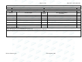
9.4
Limited-energy circuit
P
(see Form A.19)
P
a) Potential not more than 30 r.m.s. and 42.4 V
peak, or 60 V dc
P
b) Current limited by one of following means:
P
1) Inherently or by impedance (see Table 17);
or
9.5
P
the output of battery is
considered inherently limitedenergy circuit
P
2) Over current protective device (see Table
18); or
N
3) A regulating network limits also in SINGLE
FAULT CONDITION (see Table 17)
N
c) Is separated by at least BASIC INSULATION
N
Fuse or a nonadjustable electromechanical device is
used
N
Requirements for equipment containing or using
flammable liquids
N
Flammable liquids contained in or specified for use
with equipment do not cause spread of fire
RISK is reduced to a tolerable level :
TRF No. IEC61010_1F
(see Form A.20)
N
N
TRF originator: VDE
Page 28 of 92
Report No. CSTS140227045
IEC/EN 61010-1
Clause
Requirement + Test
Result - Remark
Verdict
a) The temperature of surface or parts in contact
with flammable liquids is 25 °C below fire point
N
b) The quantity of liquid is limited
N
c) Flames are contained within the equipment
N
N
Detailed instructions for RISK-reduction provided
9.6
Overcurrent protection
9.6.1
MAINS supplied equipment protected
BASIC INSULATION between MAINS parts of opposite
polarity provided
Appliance not energized by
mains.
N
N
(see Form A.14)
N
Devices not in the protective conductor
N
Fuses or single-pole circuit-breakers not fitted in
neutral (multi-phase)
N
PERMANENTLY CONNECTED EQUIPMENT
N
Overcurrent device:
N
Fitted within the equipment; or
N
Specified in manufacturer's instructions
N
Other equipment
N
Protection within the equipment
N
10
EQUIPMENT TEMPERATURE LIMITS AND
RESISTANCE TO HEAT
P
10.1
Surface temperature limits for protection against
burns
P
9.6.2
9.6.3
Easily touched surfaces within the limits in NORMAL
and in SINGLE FAULT CONDITION:
10.2
10.3
(see Form A.21A)
P
- at an specified ambient temperature of 40 °C
P
- for equipment rated above 40 °C ambient
temperature limits not exceeded raised by the
difference to 40 °C
N
Heated surfaces necessary for functional reasons
exceeding specified values:
N
Are recognizable as such by appearance or
function; or
N
Are marked with symbol 13
N
Guards are not removable without tool
N
Temperatures of windings
N
Limits not exceeded in:
N
NORMAL CONDITION
N
SINGLE FAULT CONDITION
N
Other temperature measurements
P
Following measurements conducted if applicable:
TRF No. IEC61010_1F
(see Form A.21A)
P
TRF originator: VDE
Page 29 of 92
Report No. CSTS140227045
IEC/EN 61010-1
Clause
Requirement + Test
Result - Remark
Verdict
a) Value of 60 °C of field-wiring terminal box not
exceeded
N
b) Surface of flammable liquids and parts in
contact with this liquids
N
c) Surface of non-metallic ENCLOSURES
P
d) Parts made of insulating material supporting
parts connected to MAINS supply
N
e) Terminals carrying a current more than 0,5 A
N
10.4
Conduct of temperature test
P
10.4.1
Tests conducted under reference test conditions and (see Form A.21A)
manufacturer’s instructions
P
10.4.2
Temperature measurement of heating equipment
N
Tests conducted in test corner
10.4.3
(see Form A.21A)
N
Equipment intended for installation in a cabinet or
wall
Equipment built in as specified in installation
instructions
N
(see Form A.21A)
N
10.5
Resistance to heat
10.5.1
Integrity of CLEARANCE and CREEPAGE DISTANCES
(see Form A.13)
P
10.5.2
Non-metallic ENCLOSURES
(see Form A.22)
P
10.5.3
P
Within 10 min after treatment:
—
Equipment subjected to suitable stresses of 8.2 and
8.3 complying with criteria of 8.1
P
Insulating material
Plastic for enclosure
P
a) Parts supporting parts connected to MAINS
supply
Battery operated, not connect
to the mains
N
N
b) TERMINALS carrying a current more than 0.5 A
Examination of material data; or
N
in case of doubt:
N
1) Ball pressure test; or
N
2) Vicat softening test of ISO 306
N
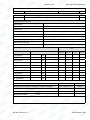
11
PROTECTION AGAINST HAZARDS FROM
FLUIDS
—
11.1
Protection to OPERATORS and surrounding area
provided by EQUIPMENT
N
All fluids specified by manufacturer considered
N
11.2
Cleaning
(see Form A.24)
N
11.3
Spillage
(see Form A.24)
N
11.4
Overflow
(see Form A.24)
N
11.5
Battery electrolyte
N
Battery electrolyte leakage presents no HAZARD
N
TRF No. IEC61010_1F
TRF originator: VDE
Page 30 of 92
Report No. CSTS140227045
IEC/EN 61010-1
Clause
Requirement + Test
Result - Remark
Verdict
11.6
Specially protected equipment
(see Form A.24)
N
11.7
Fluid pressure and leakage
11.7.1
Maximum pressure ............................................... :
11.7.2
N
(see Form A.25)
N
Maximum pressure of any part does not exceed
PRATED
N
Leakage and rupture at high pressure
N
Fluid containing parts subjected to hydraulic test if:
(see Form A.25)
N
a) product of pressure and volume > 200 kPal;
and
N
b) pressure > 50 kPa
N
Parts of refrigerating systems meets pressure-related
requirements of IEC 60335-24 or IEC 60335-24
N
11.7.3
Leakage from low-pressure parts
(see Form A.25)
11.7.4
Overpressure safety device
N
Does not operate in NORMAL USE
N
a) Connected as close as possible to parts
intended to be protected
N
b) Easy access for inspection, maintenance and
repair
N
c) Adjustment only with TOOL
N
d) No discharge towards person
N
e) No HAZARD from deposit of discharged material
N
f)
N
Adequate discharge capacity
N
No shut-off valve between overpressure safety
device and protected parts
N
12
PROTECTION AGAINST RADIATION, INCLUDING
LASER SOURCES, AND AGAINST SONIC AND
ULTRASONIC PRESSURE
N
12.1
Equipment provides protection
N
12.2
Equipment producing ionizing radiation
N
12.2.1
Ionizing radiation
12.2.1.1
Equipment meets the following requirements:
N
a) if intended to emit radiation meets requirements
of 12.2.1.2; or
N
tested, classified and marked in accordance to
IEC 60405
12.2.1.2
(see Form A.26)
N
N
b) if only emits stray radiation meets requirements
of 12.2.1.3
N
Equipment intended to emit radiation
N
Effective dose rate of radiation measured .............. :
N
TRF No. IEC61010_1F
TRF originator: VDE
Page 31 of 92
Report No. CSTS140227045
IEC/EN 61010-1
Clause
12.2.1.3
12.2.2
12.3
12.4
Requirement + Test
Result - Remark
Verdict
If dose rate exceeds 5 µSv/h marked with the
following:
N
a) Symbol 17 (ISO 361)
N
b) Abbreviations of the radionuclides .................. :
N
c) With maximum dose at 1 m; or ....................... :
N
with dose rate value between 1 µSv/h and 5
µSv/h in m .......................................................... :
N
Equipment not intended to emit radiation
N
Limit for unintended stray radiation of 1 µSv/h at any
easily reached point kept ........................................ :
N
Accelerated electrons
N
Compartments opened only by the use of a TOOL
N
Ultraviolet (UV) radiation
N
No unintentional HAZARDOUS escape of UV radiation:
—
- checked by inspection; and
N
- evaluation of RISK assessment documentation
N
Micro-wave radiation
N
2
Power density does not exceed 10 W/m ............. :
N
12.5
Sonic and ultrasonic pressure
N
12.5.1
Sound level
12.5.2
12.6
(see Form A.27)
N
No HAZARDOUS sound emission
N
Maximum sound pressure level measured and
calculated for maximum sound power level as
specified in ISO 3746 or ISO 9614-1
N
Instruction describes measures for protection
N
Ultrasonic pressure
(see Form A.27)
N
Equipment not intended to emit ultrasound does not
exceed limit of 110 dB between 20 kHz and 100 kHz
N
Equipment intended to emit ultrasound:
N
Outside useful beam does not exceed limit of 110 dB
between 20 kHz and 100 kHz
N
If inside useful beam above values exceeded:
N
Marked with Symbol 14 of Table 1
N
and following information in the documentation:
N
a) dimensions of useful beam
N
b) area where ultrasonic pressure exceed 110 dB
N
c) maximum sound pressure inside beam area
N
Laser sources
N
Equipment meets requirements of IEC 60825-1
N
TRF No. IEC61010_1F
TRF originator: VDE
Page 32 of 92
Report No. CSTS140227045
IEC/EN 61010-1
Clause
Requirement + Test
13
PROTECTION AGAINST LIBERATED GASES,
EXPLOSION AND IMPLOSION
N
13.1
Poisonous and injurious gases
N
No poisonous or injurious gases or substances
liberated in NORMAL CONDITION
N
Attached data/test reports demonstrate conformity
N
13.2
Explosion and implosion
N
13.2.1
Components
N
Components liable to explode:
—
Pressure release device provided; or
N
Apparatus incorporates operator
protection (see also 7.7)
N
Pressure release device:
—
Discharge without danger
N
Cannot be obstructed
N
13.2.2
13.2.3
Batteries and battery charging
(see Form A.28)
Verdict
N
If explosion or fire HAZARD could occur:
—
Protection incorporated in the equipment; or
N
Instructions specify batteries with built-in protection
N
In case of wrong type of battery used:
—
No HAZARD; or
N
Warning by marking and within instructions
N
Equipment with means to charge rechargeable
batteries:
—
Warning against the charging of non-rechargeable
batteries; and
N
Type of rechargeable battery indicated; or
N
Symbol 14 used
N
Battery compartment design
N
Single component failure
N
Polarity reversal test
N
Implosion of cathode ray tubes
N
If maximum face dimensions > 160 mm................. :
—
Intrinsically protected and correctly mounted; or
N
ENCLOSURE
14
Result - Remark
provides protection:
N
If non-intrinsically protected:
—
Screen not removable without TOOL
N
If glass screen, not in contact with surface of tube
N
COMPONENTS AND SUBASSEMBLIES
P
TRF No. IEC61010_1F
TRF originator: VDE
Page 33 of 92
Report No. CSTS140227045
IEC/EN 61010-1
Clause
Requirement + Test
Result - Remark
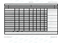
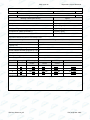
14.1
Where safety is involved, components and
subassemblies meet relevant requirements
(see Table 3)
14.2
Motors
N
14.2.1
Motor temperatures
N
Does not present a HAZARD when stopped or
prevented form starting; or
14.2.2
14.3
14.5
P
(see Form A.21)
N
Protected by over-temperature or thermal protection
device conform with 14.3
N
Series excitation motors
N
Connected direct to device, if over-speeding causes
a HAZARD
N
Overtemperature protection devices
N
Devices operating in a SINGLE FAULT CONDITION
14.4
Verdict
N
(see Form A.29)
a) Reliable function is ensured
N
b) RATED to interrupt maximum current and
voltage
N
c) Does not operate in NORMAL USE
N
If self-resetting device used to prevent a HAZARD,
protected part requires intervention before restarting
N
Fuse holders
N
No access to HAZARDOUS LIVE parts
N
MAINS voltage selecting devices
N
Accidental change not possible
N
14.6
MAINS transformers tested outside equipment
14.7
Printed circuit boards
P
Data shows conformity with V-1 of IEC 60695-11-10 V-0
or better; or
P
Test shows conformity with V-1 of IEC 60695-11-10 (see Form A.18)
or better
N
Not applicable for printed wiring boards with limitedenergy circuits (9.4)
N
Circuits or components used as transient
overvoltage limiting devices
N
14.8
Test conducted between each pair of MAINS SUPPLY
(see Forms A.30 and A.31)
(see Form A.32)
N
N
TERMINALS
15
No HAZARD resulting from rupture or overheating of
the component:
N
- no bridging of safety relevant insulation
N
- no heat to other parts above the self-ignition points
N
PROTECTION BY INTERLOCKS
N
TRF No. IEC61010_1F
TRF originator: VDE
Page 34 of 92
Report No. CSTS140227045
IEC/EN 61010-1
Clause
Requirement + Test
15.1
Interlocks are designed to remove a HAZARD
before OPERATOR exposed
N
15.2
Prevention of reactivation
N
15.3
Reliability
N
Single fault unlikely to occur; or
N
Cannot cause a HAZARD
N
16
HAZARDS RESULTING FROM APPLICATION
P
16.1
REASONABLY FORESEEABLE MISUSE
P
No HAZARDS arising from settings not intended and
not described in the instructions
P
Other cases of REASONABLY FORESEEABLE MISUSE
addressed by RISK assessment
P
Ergonomic aspects
P
Factors giving rise to a HAZARD the RISK assessment
is reflecting those aspects:
P
a) limitation of body dimensions
P
b) displays and indicators
P
c) accessibility and conventions of controls
P
d) arrangement of TERMINALS
P
RISK assessment
N
RISK assessment conducted, if HAZARD might arise
and not covered by Clauses 6 to 16
N
TOLERABLE RISK achieved by iterative documented
process covering the following:
N
a) RISK analysis
N
16.2
17
Identifies HAZARDS and estimates RISK
b) RISK evaluation
Plan to judge acceptability of resulting RISK level
based on the estimated severity and likelihood of
a RISK
c) RISK reduction
Result - Remark
Verdict
N
N
N
N
Initial RISK reduced by counter measures;
N
Repeated RISK evaluation without new RISKS
introduced
N
RISKS remaining after RISK assessment addressed in
instructions to RESPONSIBLE BODY:
N
Information contained how to mitigate these RISKS
N
Following principles in methods of RISK reduction
applied by manufacturer in given order:
N
1) RISKS eliminated or reduced as far as possible
N
TRF No. IEC61010_1F
TRF originator: VDE
Page 35 of 92
Report No. CSTS140227045
IEC/EN 61010-1
Clause
Requirement + Test
Result - Remark
Verdict
N
2) Protective measures taken for RISKS that cannot
be eliminated
N
3) User information about residual RISK due to any
defect of the protective measures
Indication of particular training is required
N
Specification of the need for personal protective
equipment
N
N
Conformity checked by evaluation of the RISK
assessment documentation
ANNEX F
ROUTINE TESTS
Manufacturer ´s declaration
TRF No. IEC61010_1F
Carried out by manufacturer.
N
N
TRF originator: VDE
Page 36 of 92
Report No. CSTS140227045
IEC/EN 61010-1
Clause
Requirement — Test
4.4.2
TABLE: Summary of SINGLE FAULT CONDITIONS
Subclause
Title
Result — Remark
Does not
apply
4.4.2.1
SINGLE FAULT CONDITIONS not covered by
4.4.2.2 to 4.4.2.14
4.4.2.2
PROTECTIVE IMPEDANCE
X
4.4.2.3
PROTECTIVE CONDUCTOR
X
4.4.2.4
Equipment or parts for short-term or
intermittent operation
X
4.4.2.5
Motors
X
– stopped while fully energized
X
– prevented from starting
X
– one phase interrupted (multi-phase)
X
4.4.2.6
Capacitors
X
4.4.2.7
MAINS transformers
Attach drawing of MAINS transformers
showing all protective devices
(see Forms A.30 and A.31)
X
4.4.2.8
Outputs
4.4.2.9
Equipment for more than one supply
X
4.4.2.10
Cooling
X
– air holes closed
X
– fans stopped
X
– coolant stopped
X
– loss of cooling liquid
X
Heating devices
X
– timer overridden
X
– temperature controller overridden
X
4.4.2.12
Insulation between circuits and parts
X
4.4.2.13
Interlocks
X
4.4.2.14
Voltage selectors
X
4.4.2.11
Verdict
Form A.1
Carried
out
X
P
Comments
see Form A.2
X
List below all SINGLE FAULT CONDITIONS not covered by 4.4.2.2 to 4.4.2.14:
-
semi-conductor components shortcircuited.
X
Supplementary information:
(see Form A.2 for details of tests)
TRF No. IEC61010_1F
TRF originator: VDE
Page 37 of 92
Report No. CSTS140227045
IEC/EN 61010-1
Clause
Requirement — Test
4.4
TABLE: Testing in SINGLE FAULT CONDITION – Results
Fault No.
Result — Remark
Fault description
Verdict
Form A.2
Td 4.4.3
(NOTE)
How was test terminated
Comments
P
Meets
4.4.4
1
Short D1
00:10:00
Unit shutdown immediately, no hazard.
Yes
2
Short C7
00:10:00
Similar normal operation, no hazard.
Yes
3
Short R9
00:10:00
Similar normal operation, no hazard.
Yes
4
Short D2
00:30:00
Unit shutdown immediately, no hazard.
Yes
5
Battery reverse
00:30:00
Not operate, no hazard.
Yes
NOTE Td = Test duration in hh:mm:ss
Record dielectric strength test on Form A.14 and temperature tests on Form A.21.
Record in the comments column for each test whether carried out during or after SINGLE FAULT CONDITION.
Supplementary information:
TRF No. IEC61010_1F
TRF originator: VDE
Page 38 of 92
Report No. CSTS140227045
IEC/EN 61010-1
Clause
Requirement — Test
Result — Remark
5.1.3c)
TABLE: MAINS supply
Verdict
Form A.3
V
N
Marked rating.........................:
--
—
Phase ....................................:
--
Frequency .............................:
--
Hz
—
Current ..................................:
--
A
—
Power ...................................:
--
W
—
Power ...................................:
--
VA
—
—
Test
Voltage
Frequency
Current
Power in
Power in
No.
V
Hz
A
W
VA
Comments
1
2
3
Note – Measurements are only required for marked ratings.
Supplementary information:
TRF No. IEC61010_1F
TRF originator: VDE
Page 39 of 92
Report No. CSTS140227045
IEC/EN 61010-1
Clause
Requirement — Test
5.3
TABLE: Durability of markings
Result — Remark
Verdict
Form A.4
Marking method (see NOTE)
P
Agent
1) Adhesive label
A Water
2) Ink printed
B Isopropyl alcohol 70%
3) Laser marked
C (specify agent)
4) Filmcoated (plastic foil control panel)
D (specify agent)
5) Imprinted on plastic (moulded in)
E (specify agent)
NOTE – Where applicable include print method, label material, ink or paint type,
fixing method, adhesive and surface to which marking is fixed.
Marking location
Marking method (see above)
Identification (5.1.2)
3
MAINS supply (5.1.3)
--
Fuses (5.1.4)
3
terminals and operating devices (5.1.5.2)
--
Switches and circuit breakers (5.1.6)
--
Double/reinforced equipment (5.1.7)
5
Field wiring Terminal boxes (5.1.8)
--
Warning marking (5.2)
5
Battery charging (13.2.2)
--
Method
Test agent
Remains legible
Label loose
Curled edges
Verdict
Verdict
Verdict
Comments
3
A/B
Yes / No
Yes / No
Yes / No
P / F / NA
3
A/B
Yes / No
Yes / No
Yes / No
P / F / NA
5
A/B
Yes / No
Yes / No
Yes / No
P / F / NA
5
A/B
Yes / No
Yes / No
Yes / No
P / F / NA
Supplementary information:
TRF No. IEC61010_1F
TRF originator: VDE
Page 40 of 92
Report No. CSTS140227045
IEC/EN 61010-1
Clause
Requirement — Test
Result — Remark
6
TABLE: Protection against electric shock - Block diagram of system Form A.5
Pollution degree ....... : 2
Verdict
P
Overvoltage category ...................: 600V CATII
Location or
Insulation
type
Maximum
working
description
(NOTE 1)
voltage
(NOTE 2)
PWB
mm
CTI
Other
mm
Two
terminals of
fuse
BI
600V
>6.0
--
Live parts to
enclosure
RI
600V
-
-
NOTE 1 – Type of insulation:
BI = BASIC INSULATION
DI = DOUBLE INSULATION
PI = PROTECTIVE IMPEDANCE
RI = Reinforced INSULATION
SI = Supplementary INSULATION
CREEPAGE Distance
(NOTE 3)
CLEARANCE
(NOTE 3)
Test
voltage
CTI
mm
(NOTE 2)
V
--
--
>3.0
2210 V rms
--
>12.0
-
>6.0
3510V rms
--
NOTE 2 - Types of voltage
Peak impulse test voltage (pulse)
r.m.s.
d.c.
peak
Comments
NOTE 3 - INSTALLATION CATEGORIES
(OVERVOLTAGE CATEGORIES)
or POLLUTION DEGREES which differ from
these should be shown under "Comments".
Supplementary Information:
TRF No. IEC61010_1F
TRF originator: VDE
Page 41 of 92
Report No. CSTS140227045
IEC/EN 61010-1
Clause
Requirement — Test
Result — Remark
Verdict
6.2
TABLE: List of ACCESSIBLE parts
6.1.2
Exceptions
—
6.2
Determination of ACCESSIBLE parts
—
Form A.6
P
Item
Description
Determination method
(NOTE 5)
Exception under 6.1.2
(NOTE 4)
1
Enclosure
Visual, test finger and
rigid test finger
--
NOTE 1 – Test fingers and pins are to be applied without force unless a force is specified (see 6.2.2)
NOTE 2 – Special consideration should be given to inadequate insulation and high voltage parts (see 6.2)
NOTE 3 – Parts are considered to be ACCESSIBLE if they could be touched in the absence of any covering which is not considered
to provide suitable insulation (see 6.4).
NOTE 4 – Capacitor test may be required (see Form A.7).
NOTE 5 – The determination methods are:
V = visual; R = rigid test finger; J = jointed test finger; P3 = pin 3 mm diameter; P4 = pin 4 mm diameter.
Supplementary information:
TRF No. IEC61010_1F
TRF originator: VDE
Page 42 of 92
Report No. CSTS140227045
IEC/EN 61010-1
Clause
Requirement — Test
6
TABLE: Values in NORMAL CONDITION
6.1.2
Exceptions
11.2 Cleaning and decontamination
—
6.3.1
Values in NORMAL CONDITION (see NOTE 1)
11.3 Spillage
—
6.6.2
Terminals for external circuit
11.4 Overflow
—
6.10.3
Plugs and connections
Item
(see
Form A.6)
Enclosure
to test
reference
earth
Result — Remark
Verdict
Form A.7
P
—
Voltage
Current
Capacitance
10 s / 5 s test (NOTE)
V
r.m.s.
V
peak
V
d.c.
Test
circuit
A1/A2/A3
mA
r.m.s.
mA
peak
mA
d.c.
μC
mJ
V
μC
mJ
68.7
97.1
--
A1
0.011
0.049
-
-
-
-
-
-
Comments
-
NOTE – A 10 s test is specified in 6.1.2 a) b). A 5 s test is specified in 6.10.3. The capacitance level versus voltage below the limits given from figure 3 of IEC 61010-1.
Supplementary information:
TRF No. IEC61010_1F
TRF originator: VDE
Page 43 of 92
Report No. CSTS140227045
IEC/EN 61010-1
Clause
Requirement — Test
Result — Remark
6.3.2
TABLE: Values in SINGLE FAULT CONDITION
Verdict
Form A.8
Item
Subclause
and
Voltage
Transient
(see NOTE)
Current
(see
Form A.6)
fault No.
(see Form A.2)
V
r.m.s.
V
peak
V
d.c.
s
Test
circuit
A1/A2/A3
mA
r.m.s.
mA
peak
mA
d.c.
μF
(see NOTE)
Comments
V
Enclosure
to
reference
earth
Short C7
65.8
93.1
--
--
--
A1
0.010
0.047
--
--
--
Enclosure
to
reference
earth
Short R9
69.1
97.7
--
--
--
A1
0.011
0.048
--
--
--
P
Capacitance
NOTE – Transient voltages must be below the limits given from Figure 2 and the capacitance below the limits from figure 3 of IEC 61010-1.
Supplementary information:
TRF No. IEC61010_1F
TRF originator: VDE
Page 44 of 92
Report No. CSTS140227045
IEC/EN 61010-1
Clause
Requirement — Test
Result — Remark
6.5.2.2
TABLE: Cross-sectional area of bonding conductors
CONDUCTOR LOCATION
Verdict
Form A.9
CROSS-SECTIONAL AREA
mm²
N
VERDICT
Pass
6.5.2.3
N
TABLE: Tighting torque test
Conductor location
Size of screw
Tighting
torque
Nm
Verdict
Supplementary information:
6.5.2.4
TABLE: Bonding impedance of plug connected equipment
ACCESSIBLE
part under test
Test
current
A
Voltage attained
after 1 min
V (NOTE 2)
Form A.10
Calculated resistance
(Maximum 0,1 or 0,2 Ω)
Ω (NOTE 1)
N
Verdict
NOTE 1 – For none-detachable power cord the impedance between protective conductor plug pin of MAINS cord and each ACCESSIBLE
part shall not exceed 0,2 Ohm.
Supplementary information:
6.5.2.5
N
TABLE: Bonding impedance of permanently connected equipment
ACCESSIBLE
Test
current
A
part under test
Voltage attained after 1 min
(maximum 10 V)
V
Verdict
Supplementary information:
6.5.2.6
TABLE: Transformer PROTECIVE BONDING screen
Test current
ACCESSIBLE
part under test
(see NOTE)
A
Voltage attained
after 1 min
(maximum 10 V)
V
Form A.11
Calculated resistance
(maximum 0,1 Ω)
Ω
N
Verdict
NOTE – Test current must be twice the value of the overcurrent protection means of the winding. Test is specified in 6.5.2.6 a) or b).
Supplementary information:
TRF No. IEC61010_1F
TRF originator: VDE
Page 45 of 92
Report No. CSTS140227045
IEC/EN 61010-1
Clause
Requirement — Test
Result — Remark
6.5.4
TABLE: protective impedance
Component
Verdict
Form A.12
Location
A single component
Measured
Calculated
Working Current
Power
voltage
dissipation
V
A
W
Rated
Verdict
Working
Power
voltage dissipation
V
W
A combination of components
Location
Component
N
Comments
Comments
NOTE – A PROTECTIVE IMPEDANCE shall not be a single electronic device that employs electron conduction in a vacuum, gas or semiconductor.
Supplementary information:
6.5.6
TABLE: Current- or voltage-limiting device
Component
Location
---
---
N
Measured
Working
Current
voltage
V
A
---
---
Rated
Working Current
voltage
V
A
---
---
Verdict
---
Comments
---
Supplementary information:
TRF No. IEC61010_1F
TRF originator: VDE
Page 46 of 92
Report No. CSTS140227045
IEC/EN 61010-1
Clause
Requirement — Test
6.7
TABLE: CLEARANCES and CREEPAGE distances
6.4.2
ENCLOSURES and protective barriers
8
Mechanical resistance to shock and impact
—
6.4.4
Impedance
9.6.1
Overcurrent protection basic insulation between MAINS parts
—
6.5.4
Protective impedance
10.5.1 Integrity of CLEARANCES and CREEPAGE distances
6.5.6
Current- or voltage-limiting device
Location
Measured
(initial – 6.7)
(see Form
A.5)
CREEPAGE CLEARANCE
DISTANCE
Result — Remark
Verdict
Form A.13
P
—
—
Mechanical tests (note)
Applied
force
N
Verdict
Rigidity
(8.2)
Static Impact
(8.2.1) (8.2.2)
Test at Measured after test Verdict
max.
(if required)
Drop
RATED
(8.3)
ambient
Normal Hand-held/ (10.5.1)
(8.3.1) Plug-in
mm
mm
Two terminals
of fuse
>6.0
>3.0
P
30N
P
P
P
--
Live parts to
enclosure
>12.0
>6.0
P
30N
P
P
P
--
Comments
CREEPAGE CLEARANCE
DISTANCE
mm
mm
40°C
>6.0
>3.0
P
BI
40°C
>12.0
>6.0
P
RI
NOTE – Refer to Form A.14 for dielectric strength tests following the above tests.
Supplementary information:
TRF No. IEC61010_1F
TRF originator: VDE
Page 47 of 92
Report No. CSTS140227045
IEC/EN 61010-1
Clause
Requirement — Test
6.8
TABLE: Dielectric strength tests
4.4.4.1 b)
Conformity after application of SINGLE FAULT CONDITIONS
6.4
Primary means of protection2
P
6.6
Connections to external circuits
N
6.7.
Insulation requirements2 (see Annex K)
6.10.2
Fitting of non-detachable MAINS supply cords
9.2 a) 2)
Eliminating or reducing the sources of ignition within the equipment
N
9.4 c)
Limited-energy circuit
N
9.6.1
Overcurrent protection basic insulation between MAINS - parts
1
Result — Remark
Verdict
Form A.14
P
P
1
P
N
1
N
2
Record the fault, test or treatment applied before the dielectric strength test. Humidity preconditioning required.
Test site altitude ....................................................... :
100m
—
Test voltage correction factor (see Table 10)........... :
NA
—
Location or
references from
Forms A.2 and A.5
Clause or
sub-clause
Two terminals
of fuse
Live parts to
enclosure
Humidity
Yes/No
Working
voltage
V
Test voltage
r.m.s./peak/d.cV
Comments
Verdict
4.4.4.1 b),
6.4, 6.7
Yes
600V rms
2210 V rms
BI
P
4.4.4.1 b),
6.4, 6.7
Yes
600V rms
3510 V rms
RI
P
Supplementary information:
6.10.2
TABLE: Cord anchorage
Location
Mass
kg
Form A.15
Pull
N
Dielectric strength test for 1 min. (6.8.3.1)............. :
Verdict
Torque
Nm
Verdict
N
Comment
V r.m.s.
Supplementary information:
TRF No. IEC61010_1F
TRF originator: VDE
Page 48 of 92
Report No. CSTS140227045
IEC/EN 61010-1
Clause
Requirement — Test
7.
TABLE: Protection against mechanical HAZARDS
7.3.4
Limitation of force and pressure
7.3.5
Gap limitations between moving parts
Part / Location
Clause 7.3.4
Continuous
Temporary
Contact présure max. 250 N /
max. 50 N /cm²
3 cm² @
@ max. 150 N
max. 0,75 s
Enclosure
max. 50 N /cm² max. 250 N /
@ max. 150 N 3 cm² @
max. 0,75 s
Result — Remark
Verdict
Form A.16
P
—
—
Torso
500
--
Clause 7.3.5.1
Minimum gaps (mm)
Head Leg Foot Toes Arm
300 180 120 50 120
--
--
--
--
--
Clause 7.3.5.2
Maximum gaps (mm)
Hand Finger Head Foot Finger Verdict
100
25
120
35
4
--
--
--
--
--
Comments
P
Supplementary information:
9
TABLE: Protection against the spread of fire
Item
1
Source of HAZARD or area of the equipment
considered (circuit, component, liquid etc.)
All live parts
Form A.17
Protection
Method
(9a, 9b or 9c)
9c
Protection details
Fire enclosure provided
P
Verdict
P
Supplementary information:
TRF No. IEC61010_1F
TRF originator: VDE
Page 49 of 92
Report No. CSTS140227045
IEC/EN 61010-1
Clause
Requirement — Test
Result — Remark
9.3.2
TABLE: Constructional requirements
14.7
Printed circuit boards
Verdict
Form A.18
N
N
Material tested ............................................................ :
—
Generic name ............................................................. :
—
Material manufacturer................................................. :
—
Type ............................................................................ :
—
Colour ......................................................................... :
—
Conditioning details .................................................... :
—
Sample 1
Thickness of specimen
mm
Duration of flaming after first Application
s
Duration of flaming plus glowing
After second application
s
Specimen burns to holding clamp
Yes/No
Cotton ignited
Yes/No
Sample result
Pass/Fail
Sample 2
Sample 3
Supplementary information:
Recognized PCB material used
TRF No. IEC61010_1F
TRF originator: VDE
Page 50 of 92
Report No. CSTS140227045
IEC/EN 61010-1
Clause
Requirement — Test
Result — Remark
9.4
TABLE: Limited-energy circuit
Item
9.4 a)
or
Location
Maximum potential in
circuit voltage
r.m.s./d.c.
V
(see Form A.17)
Verdict
Form A.19
9.4 b) Current and power limitation
Maximum
available
current
A
Maximum
available
power
VA
Overload
protection
after 120 s
A
9.4 c)
Decision
Circuit
separation
Yes/No
P
Comments
Supplementary information: battery supplied and is considered limited –energy circuit
TRF No. IEC61010_1F
TRF originator: VDE
Page 51 of 92
Report No. CSTS140227045
IEC/EN 61010-1
Clause
Requirement — Test
Result — Remark
9.5
TABLE: Requirements for equipment containing or using flammable liquids
Type of liquid
Verdict
Form A.20
9.5 Flammable liquids
b) Quantity
N
Verdict
c) Containment
Supplementary information:
TRF No. IEC61010_1F
TRF originator: VDE
Page 52 of 92
Report No. CSTS140227045
IEC/EN 61010-1
Clause
Requirement — Test
Result — Remark
Verdict
10.
TABLE : Temperature Measurements
10.1
Surface temperature limits - NORMAL CONDITION and / or SINGLE FAULT CONDITION
P
10.2
Temperature of windings- NORMAL CONDITION and / or SINGLE FAULT CONDITION
N
10.3
Other temperature measurements
N
Form A.21A
P
Operating conditions: Normal operation.
Frequency ............... :
-- Hz Test room ambient temperature (ta)
.................................:
25.0 °C
Voltage.................... :
-- V
2 h
Part / Location
Test duration ...........:
tm
°C
25.6
tc
°C
40.6
Enclosure
25.8
PCB
Button surface
Verdict
tmax
°C
85
P
40.8
85
P
26.2
41.2
130
P
C7
26.3
41.3
105
P
Internal wire
26.5
41.5
80
P
Interior surface of enclosure
26.9
41.9
Ref.
P
Ambient
25.0
40
--
--
15 min
Comments
NOTE 1 - tm = measured temperature
tc = tm corrected (tm–ta+ 40 °C or max. RATED ambient)
tmax = maximum permitted temperature
NOTE 2 - see also 14.1 with reference to component operating conditions
NOTE 3 - Record values for NORMAL CONDITION and / or SINGLE FAULT CONDITION in this Form use additional form if necessary
NOTE 4 - see Form A.21B for details of winding temperature measurements
Supplementary information:
TRF No. IEC61010_1F
TRF originator: VDE
Page 53 of 92
Report No. CSTS140227045
IEC/EN 61010-1
Clause
Requirement — Test
Result — Remark
10.2
TABLE: Temperature of windings
Resistance method Temperature Measurements
4.4.2.7
MAINS transformers
14.2.1
Motor temperatures
Verdict
Form A.21B
N
Operating conditions .... :
Frequency ................... :
Hz Test room ambient temperature (ta1/ta2)
................................ :
Voltage........................ :
V
Part / Designation
Rcold
Ω
/
°C (initial / final)
Test duration ........... :
Rwarm Current
A
Ω
tr
K
h
tc
°C
tmax
°C
Verdict
min
Comments
NOTE 1- Rcold = initial resistance
Rwarm = final resistance
tr = temperature rise
tc = tr corrected (tc= tr - { ta2 - ta1} + [40 °C or max RATED ambient])
tmax = maximum permitted temperature
NOTE 2 - Indicate insulation class (IEC 60085) under comments (optional)
NOTE 3 - Record values for NORMAL CONDITION and / or SINGLE FAULT CONDITION in this Form use additional form if necessary
Supplementary information:
10.5.2
TABLE: Resistance to heat of non-metallic ENCLOSURES
Form A.22
P
Test method used....................................................: a)
—
Non operative treatment..........................................: [√ ]
P
Empty ENCLOSURE ...................................................: [ ]
N
Operative treatment.................................................: [ ]
N
Temperature during tests ........................................: 70°C
—
ENCLOSURE samples tested were............................:
—
Description
Material
Comments
Verdict
Enclosure
V-0
No damage
P
Dielectric strength test (6.8)…………………………: 3510
V r.m.s./peak/d.c.
P
NOTE – Within 10 minutes of the end of treatment suitable tests in acc. to 8.2 and 8.3 must be conducted and pass criteria of 8.1.
Supplementary information:
TRF No. IEC61010_1F
TRF originator: VDE
Page 54 of 92
Report No. CSTS140227045
IEC/EN 61010-1
Clause
Requirement — Test
Result — Remark
Verdict
10.5.3
TABLE: Insulating Materials
10.5.3 1)
Ballpressure test
P
Max. allowed impression diameter..........................: 2 mm
—
Form A.23
P
Part
Test temperature
°C
Impression Diameter
(mm)
Verdict
Enclosure
70
1.1
--
125
0.7
--
PCB
Supplementary information:
10.5.3 2)
Vicat softening test (ISO 306)
N
Part
Vicat softening temperature
°C
Thickness of sample
(mm)
Verdict
--
--
--
--
Supplementary information:
TRF No. IEC61010_1F
TRF originator: VDE
Page 55 of 92
Report No. CSTS140227045
IEC/EN 61010-1
Clause
Requirement — Test
Result — Remark
8
TABLE: Mechanical resistance to shock and impact
11
Protection against HAZARDS from fluids
Verdict
Form A.24
P
N
Voltage tests can be carried out once after performing the tests of clause 8 and clause 11. However, if voltage tests are carried out separately after each set of tests, two forms can be used.
Clause 8 tests
Location
(see form A.5)
See form A.5
Clause 11 tests
Static
(8.2.1)
30 N
Impact
(8.2.2)
Normal
(8.3.1)
Handheld
Plug-in
Cleaning
(11.2)
Spillage
(11.3)
Overflow
(11.4)
IEC
60529
(11.6)
Working
voltage
V
Test
voltage
V
Verdict
Comments
√
√
√
--
--
--
--
--
600V
2210 V rms
P
BI
√
√
√
--
--
--
--
--
600V
3510 V rms
P
RI
NOTE – Use r.m.s., d.c. or peak to indicate the used test voltage.
Supplementary information:
TRF No. IEC61010_1F
TRF originator: VDE
Page 56 of 92
Report No. CSTS140227045
IEC/EN 61010-1
Clause
Requirement — Test
Result — Remark
11.7.2
TABLE: Leakage and rupture at high pressure
Maximum
permissible
working
pressure
Mpa
Part
Verdict
Form A.25
Test
pressure
Leakage
Deformation
Burst
MPa
Yes / No
Yes / No
Yes / No
N
Comments
NOTE – see also Annex G with requirements for USA and Canada.
Supplementary information:
11.7.3
N
Leakage from low-pressure parts
Part
Test
pressure
Mpa
Leakage
Comments
Yes / No
Supplementary information:
TRF No. IEC61010_1F
TRF originator: VDE
Page 57 of 92
Report No. CSTS140227045
IEC/EN 61010-1
Clause
Requirement — Test
12.2.1
TABLE: Ionizing radiation
12.2.1.2
Equipment intended to emit radiation
Locations tested
Result — Remark
Measured values
µSv/h
Verdict
Form A 26
N
Verdict
Comments
Supplementary information:
12.2.1.3
Equipment not intended to emit radiation
Max. allowed effective dose rate at 100 mm………: 1 µSv/h
Measured values
Verdict
Locations tested
µSv/h
N
—
Comments
Supplementary information:
TRF No. IEC61010_1F
TRF originator: VDE
Page 58 of 92
Report No. CSTS140227045
IEC/EN 61010-1
Clause
Requirement — Test
12.5.1
TABLE: Sound level
Locations tested
Result — Remark
Verdict
Form A.27
Measured values
dBA
N
Calculated maximum sound
pressure level
At operator’s normal position
and at bystanders’ positions
a)
b)
c)
d)
e)
f)
Supplementary information:
12.5.2
Ultrasonic pressure
Locations tested
N
Measured values
dB
Comments
kHz
At operator’s normal position
At 1 m from the ENCLOSURE
a)
b)
c)
d)
e)
NOTE – No limit is specified at present, but a limit of 110 dB above the reference pressure value of 20 μPa is under consideration for
applicable frequencies between 20 kHz and 100 kHz.
Supplementary information:
TRF No. IEC61010_1F
TRF originator: VDE
Page 59 of 92
Report No. CSTS140227045
IEC/EN 61010-1
Clause
Requirement — Test
13.2.2
TABLE: Batteries
Result — Remark
Verdict
Form A.28
P
Battery load and charging circuit diagram:
Battery type ............................................................:
L1028
—
Battery manufacturer/model/catalogue No.............:
--
—
Battery ratings ........................................................:
1×12V
—
Reverse polarity instalment test
No hazard
Single component failures
Component
Battery
Verdict
Open circuit
Short circuit
P
P
Supplementary information:
TRF No. IEC61010_1F
TRF originator: VDE
Page 60 of 92
Report No. CSTS140227045
IEC/EN 61010-1
Clause
Requirement — Test
Result — Remark
14.3
TABLE: Overtemperature protection devices
Verdict
Form A.29
N
Reliability test
Component
Type
(NOTE)
Verdict
Comments
NOTE:
NSR = non-self-resetting
(10 times)
NR = non-resetting (1 time)
SR = self-resetting (200 times)
Supplementary information:
TRF No. IEC61010_1F
TRF originator: VDE
Page 61 of 92
Report No. CSTS140227045
IEC/EN 61010-1
Clause
Requirement — Test
Result — Remark
Verdict
4.4.2.7
TABLE: MAINS transformer
4.4.2.7.2
Short circuit
N
14.6
MAINS transformers tested outside equipment
N
Form A.30
N
Type ..............................:
—
Manufacturer .................:
—
Test in equipment
Test on bench
Test repeated inside equipment (see 14.6)
Optional – Insulation class (IEC 60085) of the lowest rated winding
:
—
Winding identification
Type of Protector for winding (Note 1)
Elapsed time
Current, A
primary
secondary
Winding temperature, °C primary
(see Note 2)
secondary
Tissue paper / cheesecloth OK ?
(Pass / Fail)
Voltage tests (see Note 3)
Primary to secondary
______ V ____
Primary to core
______ V ____
Secondary to secondary ______ V ____
Secondary to core
______ V ____
Verdict
Note 1:
Note 2:
Note 3:
Primary fuse
Secondary fuse
Overtemperature protection
Impedance protection
Indicate method of measurement
- PF /
(
) A
- SF /
(
) A
- OP /
(
) °C
-Z
TC = with thermocouple
R = resistance method
If resistance method is used, record resistance in cold and warm condition in FormA.20B!
Record the voltage applied and the type of voltage (r.m.s. / d.c. / peak) and for
results use
NB = no breakdown
or
B = breakdown
Supplementary information:
TRF No. IEC61010_1F
TRF originator: VDE
Page 62 of 92
Report No. CSTS140227045
IEC/EN 61010-1
Clause
Requirement — Test
Result — Remark
Verdict
4.4.2.7
TABLE: MAINS transformer
4.4.2.7.3
Overload tests (for MAINS transformers)
N
14.6
MAINS transformers tested outside equipment
N
Form A.31
N
Type ................................ :
—
Manufacturer................... :
—
Test in equipment
Test on bench
Test repeated inside equipment (see 14.6)
Optional – Insulation class (IEC 60085) of the lowest rated winding
:
—
Winding identification
Type of Protector for winding (Note 1)
Elapsed time
Current, A
primary
secondary
Winding temperature, °C primary
(see Note 2)
secondary
Tissue paper / cheesecloth OK ?
(Pass / Fail)
Voltage tests (see Note 3)
Primary to secondary
______ V ____
Primary to core
______ V ____
Secondary to secondary
______ V ____
Secondary to core
______ V ____
Verdict
Note 1:
Note 2:
Note 3:
Primary fuse
Secondary fuse
Overtemperature protection
Impedance protection
Indicate method of measurement
- PF /
(
) A
- SF /
(
) A
- OP /
(
) °C
-Z
TC = with thermocouple
R = resistance method
If resistance method is used, record resistance in cold and warm condition in FormA.20B!
Record the voltage applied and the type of voltage (r.m.s. / d.c. / peak) and for
results use
NB = no breakdown
or
B = breakdown
Supplementary information:
TRF No. IEC61010_1F
TRF originator: VDE
Page 63 of 92
Report No. CSTS140227045
IEC/EN 61010-1
Clause
Requirement — Test
14.8
TABLE: Transient overvoltage limiting devices
Component / Designation
Result — Remark
Overvoltage MAINS voltage Test voltage
Category
V rms
V
Test room ambient temperature ….:
Verdict
Form A.32
tm
°C
tc
°C
tmax
°C
Rupture Circuit breaker Verdict
Yes / No
tripped
N
Comments
°C
NOTE - tm = measured temperature
tc = tm corrected (tm–ta+ 40 °C or max. RATED ambient)
tmax = maximum permitted temperature
Conformity is checked by applying 5 positive and 5 negative impulses with the applicable impulse withstand voltage, spaced up to 1 min apart, from a hybrid impulse generator (see IEC 61180-1).
Supplementary information:
TRF No. IEC61010_1F
TRF originator: VDE
Page 64 of 92
Report No. CSTS140227045
IEC/EN 61010-1
Clause
Requirement – Test
Result — Remark
Annex H
TABLE: Qualification of conformal coating
for
Verdict
Addition to Form A.xx
N
N
protection against pollution
Technical properties
Manufacturer ................................................. :
—
Type............................................................... :
—
Meet requirements of ANSI / UL 746E .......... : [yes / no]
Manufacturer declaration of coating material : [yes / no]
Operating temperature of coating.................. : [ ] °C
Comparative tracking index (CTI).................. : [ ]
Insulation resistance...................................... : [ ] Ω
Dielectric strength.......................................... : [ ] V
UV resistance (if required)............................. : [yes / no]
Flammability rating ........................................ :
Preparation of the test specimens
Item Test conditioning
Parameter
[yes / no]
Td
h
1
Samples
1
2
3
4
Verdic
t
5
Comments
6
Scratch resistance
Visual inspection
2
Cold
3
Dry heat
4
Rapid temp.
change
5
Damp heat
6
Adhesion of
coading
Visual inspection
7
Humidity
8
Insulation
resistance
Visual inspection
NOTE Td = Test duration time
Supplementary information:
TRF No. IEC61010_1F
TRF originator: VDE
Page 65 of 92
Report No. CSTS140227045
IEC/EN 61010-1
Clause
Requirement – Test
Result — Remark
6.7.2.2.2
TABLE: Reliability of potted components
Verdict
Addition to Form A.14
N
Temperature Cycling Test
Manufacturer................................................ :
Type ............................................................. :
Construction................................................. :
Potting compound........................................ :
CREEPAGE distances measured ................... :
CLEARANCES measured................................ :
Thickness through insulation ....................... :
Adhesive test Pass/Fail ............................... :
Test temperature T °C ................................. :
Cycles at U= AC 500 V
Leakage current (500 V)
mA
Number of cycles
Date
1. Cycle from
to
2. Cycle from
to
3. Cycle from
to
4. Cycle from
to
5. Cycle from
to
6. Cycle from
to
7. Cycle from
to
8. Cycle from
to
9. Cycle from
to
10. Cycle from
to
68 h /
125 °C
1h/
25 °C
2h/
0 °C
1h/
25 °C
After Cycling Test :
Humidity conditioning
48 h
Requirements for dielectric strength (s. insulation diagram)
Basic insulation
Verdict
______ V r.m.s.
Additional insulation
Reinforced insulation
Test voltage V r.m.s
______ V r.m.s.
______ V r.m.s.
Supplementary information:
TRF No. IEC61010_1F
TRF originator: VDE
Page 66 of 92
Report No. CSTS140227045
IEC/EN 61010-1
Clause
Requirement — Test
6.
TABLE: Working voltage of Switch Mode Power Supply
Location / Measuring track
Input supply voltage…….:
Supplementary information:
TRF No. IEC61010_1F
Result — Remark
Insulation
(Form A.5)
V
RMS voltage
V
Peak voltage
V
Verdict
Addition to Form A.5
Required Measured Required Measured Verdict
cl
cl
cp
cp
mm
mm
mm
mm
N
Comments
Hz
TRF originator: VDE
Page 67 of 92
Report No. CSTS140227045
IEC/EN 61010-2-031
Clause
Requirement + Test
4.4
Testing in SINGLE FAULT CONDITIONS
—
4.4.1
General
N
4.4.2
Application of fault conditions
4.4.2.1
PROBE ASSEMBLIES OR PARTS FOR SHORT-TERM
OR INTERMITTENT OPERATION
N
4.4.2.2
OUTPUTS
N
4.4.2.3
INSULATION BETWEEN CIRCUITS AND PARTS
N
4.4.2.4
Components
N
4.4.3
Duration of tests
N
4.4.4
Conformity after application of SINGLE FAULT
CONDITIONS
5
MARKING AND DOCUMENTATION
P
5.1.1
General
P
Markings applicable for whole probe assembly not
located on operator removable parts
Result - Remark
(see Form A.1)
N
(see Form A.2)
N
Markings molded in the probe
body
P
Letter symbols (IEC 60027) used
P
Graphic symbols (Table 1) used; or
P
Symbol
5.1.2
Verdict
used
if other symbol used; explained in accompanying
documentation
N
In case of less space for required markings:
N
- symbol 10 of table 1 used
N
- all necessary information included in documentation
N
Identification
—
Equipment is identified by:
P
5.1.2 a)
Name or registered trademark
See page 1
P
5.1.2 b)
For type B and C, also model no. or similar
Type A
N
5.1.3
5.1.4
If designed for use with specific model this is made
clear and
N
model identified by marking or in documentation
N
Fuses
No fuse employed
N
All details necessary for fuse replacement
N
Includes rated voltage and current breaking capacity
N
If selected according to particular application;
marked with symbol 10 and information in
documentation
N
TERMINALS AND OPERATING DEVICES
N
Necessary identification for TERMINALS,
connectors etc.
N
TRF No. IEC61010_2F
TRF originator: VDE
Page 68 of 92
Report No. CSTS140227045
IEC/EN 61010-2-031
Clause
Requirement + Test
5.1.6
Rating
Maximum RATED voltage to earth
Result - Remark
Verdict
P
600 V CATII
P
(CAT I) Symbol 10 used
5.2
5.3
N
(CAT II-IV) Category marked
CATII
P
Nature of voltage (ac, dc etc.)
Applicable to both r.m.s and
dc
N
Reference connector intended for connection to
voltages exceeding the values of 6.3.1.1
No reference connector
N
For type A and type D only, the maximum RATED
current unless specified for high impedance inputs
MAX 2A molded in the probe
body
P
Warning markings
P
Visible when ready for NORMAL USE
P
If necessary marked with symbol 10
P
Near or on particular parts of the PROBE
ASSEMBLY
P
Advise to disconnect or isolate during access to
HAZARDOUS LIVE parts or
N
marked with symbol 10 and information in the
instruction manual
N
Easily touched heated parts, if not self-evident,
marked with symbol 9
N
Durability of markings
P
The required markings remain clear and legible in
(see Form A.3)
P
NORMAL USE
Resist cleaning (clear, legible and not worked
loose)
P
5.4
Documentation
P
5.4.1
General
P
Documentation includes:
—
5.4.1 a)
Technical specification
P
5.4.1 b)
Instructions for use
P
5.4.1 c)
Name and address of manufacturer or supplier
P
5.4.1 d)
Information specified in 5.4.2 to 5.4.4
5.4.2
See 5.4.2 to 5.4.4
P
A clear explanation of warning symbols is in the
documentation or
P
Information is durably and legibly marked on the
equipment
P
Statement that symbol 10 means documentation
needs to be consulted
P
Ratings
P
Maximum voltage RATING
TRF No. IEC61010_2F
600V CATII
P
TRF originator: VDE
Page 69 of 92
Report No. CSTS140227045
IEC/EN 61010-2-031
Clause
Requirement + Test
Result - Remark
Maximum current RATING
MAX 2A
Verdict
P
Statement of the range of environmental conditions
P
Operation
P
Instructions for use include:
—
5.4.3 a)
Identification of operating controls
N
5.4.3 b)
Interconnection requirements
N
Specification of accessories, materials etc.
N
5.4.3 c)
Specification of intermittent operation limits
N
5.4.3 d)
Explanation of required and used symbols
P
5.4.3 e)
Replacement of consumables
N
5.4.3 f)
Definition of measurement category (if marked with
CAT)
5.4.3 g)
If marked CAT I, a warning not to use in other CAT
N
5.4.3 h)
Cleaning if necessary
P
5.4.3 i)
WARNING FOR THE LOWER CAT OF A COMBINATION OF
A PROBE ASSEMBLY AND AN ACCESSORY
N
A STATEMENT AGAINST USE IN A MANNER NOT
SPECIFIED BY THE MANUFACTURER
N
Maintenance
P
Sufficient preventive maintenance and inspection
for RESPONSIBLE BODY
P
Parts to be supplied or examined by the
manufacturer only
P
RATING and characteristics of fuses (see 5.1.3)
N
6
PROTECTION AGAINST ELECTRIC SHOCK
P
6.1
General
6.1.1
Exceptions
P
Following HAZARDOUS LIVE parts may be accessible to
an OPERATOR:
P
6.1.1 a)
Parts intended to be replaced by the operator (for
example, fuses), but only if they have a warning
marking according to 5.2
N
6.1.1 b)
PROBE TIPS, provided that they meet the
requirements of 6.4.4
6.2
Determination of accessible parts
5.4.3
5.4.4
According to figure 3
6.3
6.3.1
600V CATII
P
(see Form A.4)
P
Refer to clause 6.4.4
P
N
Obvious to determine the
accessible parts
N
Permissible limits for ACCESSIBLE parts
P
Measurements performed according to figure 4
P
Values in NORMAL CONDITION
TRF No. IEC61010_2F
see Form A.6
P
TRF originator: VDE
Page 70 of 92
Report No. CSTS140227045
IEC/EN 61010-2-031
Clause
Requirement + Test
Result - Remark
6.3.2
Values in SINGLE FAULT CONDITION
see Form A.7
6.4
Insulation requirements for protection against electric
shock
6.4.1
Connectors used on PROBE ASSEMBLIES shall
meet the applicable requirements of a) to c) below:
6.4.1 a)
Connectors in fully mated position:
N
i) Connecting probe to measuring equipment
insulated by at least basic insulation
N
ii) Intended to be HAND-HELD insulated by
DOUBLE or REINFORCED INSULATION
N
Connectors in partially mated position:
N
insulated by at least BASIC INSULATION
N
Voltage test with test finger (B.1)
N
Connectors in unmated position:
N
Except for locking or screw-held type connectors or
limited current by PROTECTIVE IMPEDANCE:
N
i) HAZARDOUS LIVE parts not ACCESSIBLE
N
Up to 1 kV a.c. or 1.5 kV d.c., not ACCESSIBLE
N
Above 1 kV a.c. or 1.5 kV d.c., voltage test with test
finger
N
ii) Stackable connectors
N
HAZARDOUS LIVE parts separated by BASIC
INSULATION from ACCESSIBLE parts
N
CLEARANCE and CREEPAGE meet the
requirements for BASIC INSULATION
N
Voltage test in acc. to 6.6
N
HAND-HELD parts other than connectors
P
6.4.1 b)
6.4.1 c)
6.4.2
6.4.3
Verdict
N
P
No such part
N
HAZARDOUS LIVE parts separated by DOUBLE or
REINFORCED INSULATION from ACCESSIBLE
parts
see Form A.4
P
CLEARANCE and CREEPAGE meet the
requirements for DOUBLE or REINFORCED
INSULATION
see Form A.9
P
Voltage test in acc. 6.6 (specify parts)
see Form A.10
P
REFERENCE CONNECTOR
N
Cables
P
RATED for maximum voltage and current of
NORMAL USE
P
DOUBLE or REINFORCED INSULATION based on
voltages (min 125 V/500 V) according to type of
PROBE ASSEMBLIES..............................................:
N
or for maximum RATED voltage...............................:
TRF No. IEC61010_2F
Rated 600V CATII
P
TRF originator: VDE
Page 71 of 92
Report No. CSTS140227045
IEC/EN 61010-2-031
Clause
6.4.4
6.4.5
6.4.6
Requirement + Test
Result - Remark
Verdict
Voltage test in acc. 6.6 (specify parts)
see Form A.10
P
PROBE TIPS
P
BARRIER providing safe distance:
P
-CLEARANCE and CREEPAGE meet the
requirements for REINFORCED INSULATION
see Form A.9
P
Spring-loaded squeeze PROBE ASSEMBLIES:
(rated for WORKING VOLTAGE ≤1 kV)
No such part
N
a) Actuation prevents touching HAZARDOUS LIVE
parts
N
b) Additional protective distance of 45 mm longer
than for barrier
N
Crocodile clips and similar without barrier: (rated for
CAT I or II)
N
- have tactile indication
N
DOUBLE INSULATION and REINFORCED
INSULATION
P
See 6.5, 6.6 and 6.7.2
P
PROTECTIVE IMPEDANCE
N
Appropriate HIGH-INTEGRITY single component
used for protection (see 12.3)
6.5
N
Components, wires and connections are suitably
RATED even for SINGLE FAULT CONDITION
N
CLEARANCES AND CREEPAGE DISTANCES
P
CLEARANCES and CREEPAGE DISTANCES
between circuits and parts
6.6
No such component
see Form A.4 and Form A.9
P
Voltage tests
P
Humidity pre-conditioning (6.6.2) conducted
P
Test voltages (6.6.4)
see Form A.4 and Form A.10
P
6.7
Constructional requirements
P
6.7.1
General
P
6.7.1 a)
Security of soldered wiring connections
N
6.7.1 b)
Screws securing removable covers are captive if
their length affects isolation distances
N
6.7.1 c)
Accidental loosening
N
The following is not used for safety purposes:
P
1) Materials which can be easily damaged (enamel
etc.)
P
2) Non-impregnated hygroscopic materials
P
ENCLOSURES of PROBE ASSEMBLIES with DOUBLE or REINFORCED
INSULATION
P
ENCLOSURE which surrounds all metal parts
P
6.7.2
TRF No. IEC61010_2F
TRF originator: VDE
Page 72 of 92
Report No. CSTS140227045
IEC/EN 61010-2-031
Clause
6.7.3
6.7.4
Requirement + Test
Result - Remark
Verdict
Small metal parts are separated from HAZARDOUS
LIVE voltages by DOUBLE or REINFORCED
INSULATION
No such part
N
ENCLOSURES or parts made of insulating material
fulfil requirements for DOUBLE or REINFORCED
INSULATION.
see Form A.4 and Form A.9
P
Protection for metal ENCLOSURES or parts is
provided by one of the following:
N
a) provision of an insulating coating or BARRIER on
the inside of the ENCLOSURE
N
b) CLEARANCES and CREEPAGE DISTANCES
cannot be reduced by loosening of parts or wires
N
Corona and partial discharge
P
No corona or partial discharge while operating at
maximum voltage
P
Cable attachment
P
Withstand forces likely to be encountered
P
6.7.4.1
Pull test
see Form A.11
P
6.7.4.2
Flexing/pull test
see Form A.11
P
6.7.4.3
Rotational flexing test
see Form A.11
P
6.7.5
Insulation of a probe cable
P
Probe cable with a wear indicator provide DOUBLE Wear indicator employed
or REINFORCED INSULATION when new, and at
least BASIC INSULATION when the wear indicator is
reached
P
PROBE CABLE without a wear indicator provide
DOUBLE or REINFORCED INSULATION
N
Voltage test in acc. 6.6 (specify parts):
7
8
see Form A.10
P
-
REINFORCED INSULATION: one unconditioned
sample before cycling treatment
P
-
BASIC INSULATION: contrasting colour became
visible during the cycling treatment
P
-
REINFORCED INSULATION: 250 cycles
treatment without contrasting colour becoming
visible.
N
PROTECTION AGAINST MECHANICAL HAZARDS
P
Handling during normal use shall not lead to hazard
P
MECHANICAL RESISTANCE TO SHOCK AND IMPACT
P
Withstand shock and impact likely to occur in
NORMAL USE
P
Conformity is checked by performing the tests of
8.1 to 8.3. The PROBE ASSEMBLY is notoperated
during the tests.
P
TRF No. IEC61010_2F
TRF originator: VDE
Page 73 of 92
Report No. CSTS140227045
IEC/EN 61010-2-031
Clause
Requirement + Test
8.2
8.3
Verdict
After completion of the tests, the PROBE
ASSEMBLY shall pass the voltage tests of 6.6
(withouthumidity preconditioning) and is inspected
to check that:
P
a) HAZARDOUS LIVE parts not accessible
P
b) ENCLOSURE shows no cracks (hazard)
P
c) CLEARANCES not less than their permitted
values
8.1
Result - Remark
(see Form A.9)
P
d) BARRIERS not damaged or loosened
P
e) No damage which could cause spread of fire
P
Rigidity test
P
20 N APPLIED THREE TIMES
P
Drop test
P
Three samples dropped
P
Impact swing test
P
Probe subjected to impact against a hardwood
board
P
After the tests of 8.1 to 8.3:
P
Voltage tests in acc. to 6.6
(see Form A.10)
P
9
TEMPERATURE LIMITS AND PROTECTION AGAINST THE SPREAD OF FIRE
P
9.1
General
P
Any heating does not cause a HAZARD in NORMAL
CONDITION nor in SINGLE FAULT CONDITION
P
No spread of fire outside the PROBE ASSEMBLY
P
Easily touched surfaces not exceeding the following
limits in NORMAL CONDITION :
P
- metal less than 55 °C
No such part
N
- non-metallic less than 70 °C
P
- wires and cables less than 75 °C
P
Temperatures in SINGLE FAULT CONDITION less
than 105 °C
N
Easily touched heated surfaces recognizable or
No such part
marked with symbol 9 of table 1 (s. 5.2), if necessary
for functional reasons
N
Circuits separated by at least by BASIC
INSULATION, if protection depends on separation of
circuits
N
9.2
Temperature tests
10
RESISTANCE TO HEAT
P
10.1
Integrity of CLEARANCES and CREEPAGE
DISTANCES
P
TRF No. IEC61010_2F
see Form A.12
P
TRF originator: VDE
Page 74 of 92
Report No. CSTS140227045
IEC/EN 61010-2-031
Clause
10.2
Requirement + Test
Result - Remark
Requirements of 6.5 are met at an ambient
temperature of 40 °C of maximum RATED ambient
temperature (if higher)
see Form A.9
Verdict
P
RESISTANCE TO HEAT
Probe assemblies with non-metallic ENCLOSURES
are resistant to elevated temperatures:
P
see Form A.13
P
11
PROTECTION AGAINST HAZARDS FROM FLUIDS
N
11.1
General
N
OPERATOR and surrounding area are protected
No fluid employed
against HAZARDS from fluids if PROBE
ASSEMBLIES containing or intended to be used with
fluids
N
Cleaning
N
Cleaning procedure applied three times to the
PROBE ASSEMBLY
N
Specially protected PROBE ASSEMBLIES
N
Where the equipment is RATED or marked by the
manufacturer the requirements of IEC 60529 are
fulfilled
N
After the tests of 11.1 to 11.3:
N
Accessible parts do not exceed the limits of 6.3.1
N
Voltage tests in acc. to 6.6
N
12
COMPONENTS
P
12.1
General
P
11.2
11.3
12.1 a)
Safety components operated within their specified
RATINGS
see Table 3, probe body and
cable
P
Components approved by a recognized testing
authority for conformity
see Table 3
P
comply with all applicable safety requirements in
relevant IEC standards
P
and subjected to the tests of this standard if
necessary for application
P
comply with all relevant requirements of this standard
N
and subjected to the tests of relevant IEC component
standard if necessary for application
N
12.1 c)
comply with all relevant requirements of this standard
only if there is no relevant IEC standard
N
12.2
Fuses
N
12.1 b)
Voltage RATING
12.3
No fuse
N
Breaking capacity and current rating...................:
N
HIGH-INTEGRITY components
N
Positions of use
TRF No. IEC61010_2F
No such component
N
TRF originator: VDE
Page 75 of 92
Report No. CSTS140227045
IEC/EN 61010-2-031
Clause
Requirement + Test
Result - Remark
Verdict
Evaluated to IEC Publications
N
A single electronic device which employs electron
conduction in a vacuum, gas or semiconductor is not
used as HIGH-INTEGRITY component
N
12.3.1
Resistors used in PROTECTIVE IMPEDANCE
N
12.3.1 a)
Withstand twice the dissipation at RATED voltage
N
12.3.1 b)
Withstand twice the RATED voltage for 1 s
N
12.3.1 c)
Distance across resistor or assembly:
N
fulfil requirements for DOUBLE or REINFORCED
INSULATION
see Form A.9
N
If heating occurs at maximum working voltage,
CLEARANCE complies with temperature corrected
value
N
13
Prevention of HAZARD from arc flash and short-circuits
P
13.1
General
P
PROBE TIPS and crocodile clips are constructed to
mitigate the risk of arc flash and short-circuits.
P
13.2
Exposed conductive parts
P
13.2. a)
PROBE ASSEMBLIES RATED for CAT III or IV,
the exposed conductive part of a PROBE
TIP ≤ 4 mm.
N
13.2. b)
Special applications within CAT I where the energy
levels not support arc flash or fire, the exposed
conductive part of a PROBE TIP ≤ 80 mm
N
13.2. c)
Other PROBE ASSEMBLIES, the exposed
conductive part of a PROBE TIP ≤ 19 mm.
13.2. d)
The outer surfaces of the jaws of crocodile or similar
clips RATED for CAT II, III, or IV are not conductive.
N
HAZARDOUS LIVE parts are not ACCESSIBLE
when closed
N
TRF No. IEC61010_2F
10.17mm
P
TRF originator: VDE
Page 76 of 92
Report No. CSTS140227045
IEC/EN 61010-2-031
Clause
Requirement — Test
4.4.2
TABLE: Summary of SINGLE FAULT CONDITIONS
Subclause
Title
4.4.2.1
EQUIPMENT OR PARTS FOR SHORT-TERM
OR INTERMITTENT OPERATION
4.4.2.2
OUTPUTS OF TYPE B AND TYPE C PROBE
ASSEMBLIES
4.4.2.3
INSULATION BETWEEN CIRCUITS AND PARTS
4.4.2.4
Components of type B and type C
PROBE ASSEMBLIES
Result — Remark
Does not
apply
Verdict
Form A.1
Carried
out
N
Comments
see Form A.2
List below all SINGLE FAULT CONDITIONS not covered by 4.4.2.1 to 4.4.2.4:
Supplementary information:
(see Form A.2 for details of tests)
TRF No. IEC61010_2F
TRF originator: VDE
Page 77 of 92
Report No. CSTS140227045
IEC/EN 61010-2-031
Clause
Requirement — Test
4.4
TABLE: Testing in SINGLE FAULT CONDITION – Results
Fault No.
Result — Remark
Fault description
Form A.2
Td 4.4.3
(NOTE)
How was test terminated
Comments
NOTE Td = Test duration in h:min:s
Record voltage test on Form A.10 and temperature tests on Form A..12
Record in the comments column for each test whether carried out during or after SINGLE FAULT CONDITION.
Supplementary information:
TRF No. IEC61010_2F
Verdict
TRF originator: VDE
N
Meets
4.4.4
Page 78 of 92
Report No. CSTS140227045
IEC/EN 61010-2-031
Clause
Requirement — Test
5.3
TABLE: Durability of markings
Result — Remark
Verdict
Form A.3
Marking method (see NOTE)
P
Agent
1) Adhesive label
A Water
2) Ink printed
B Isopropyl alcohol 70%
3) Laser marked
C (specify agent)
4) Filmcoated (plastic foil control panel)
D (specify agent)
5) Imprinted on plastic (moulded in)
E (specify agent)
NOTE – Where applicable include print method, label material, ink or paint type,
fixing method, adhesive and surface to which marking is fixed.
Marking location
Marking method (see above)
Identification (5.1.2)
5
FUSES (5.1.3)
--
TERMINALS and operating devices (5.1.4)
--
DOUBLE/REINFORCED equipment (5.1.5) 5
Rating (5.1.6)
5
Warning marking (5.2)
5
Method
Test agent
Remains legible
Label loose
Curled edges
Verdict
Verdict
Verdict
Comments
5
A/B
Yes / No
Yes / No
Yes / No
P / F / NA
5
A/B
Yes / No
Yes / No
Yes / No
P / F / NA
5
A/B
Yes / No
Yes / No
Yes / No
P / F / NA
5
A/B
Yes / No
Yes / No
Yes / No
P / F / NA
Supplementary information:
TRF No. IEC61010_2F
TRF originator: VDE
Page 79 of 92
Report No. CSTS140227045
IEC/EN 61010-2-031
Clause
Requirement — Test
Result — Remark
6
TABLE: Protection against electric shock - Block diagram of system Form A.4
Pollution degree........ : 2
Verdict
P
Overvoltage category................... : II
Location or
Insulation
type
Maximum
working
description
(NOTE 1)
voltage
(NOTE 2)
PWB
mm
CTI
Other
mm
Probe tip to
barrier
RI
600V
--
--
Probe tip to
probe body
RI
600V
--
--
NOTE 1 – Type of insulation:
BI = BASIC INSULATION
DI = DOUBLE INSULATION
PI = PROTECTIVE IMPEDANCE
RI = Reinforced INSULATION
SI = Supplementary INSULATION
CREEPAGE Distance
(NOTE 3)
CLEARANCE
(NOTE 3)
Test
voltage
CTI
mm
(NOTE 2)
V
>12.0
--
>6.0
3536 V rms
--
>12.0
--
>6.0
3536 V rms
--
NOTE 2 - Types of voltage
Peak impulse test voltage (pulse)
r.m.s.
d.c.
peak
Comments
NOTE 3 - INSTALLATION CATEGORIES
(OVERVOLTAGE CATEGORIES)
or POLLUTION DEGREES which differ from
these should be shown under "Comments".
Supplementary Information:
TRF No. IEC61010_2F
TRF originator: VDE
Page 80 of 92
Report No. CSTS140227045
IEC/EN 61010-2-031
Clause
Requirement — Test
Result — Remark
Verdict
6.2
TABLE: List of ACCESSIBLE parts
6.1.1
Exceptions
—
6.2
Determination of ACCESSIBLE parts
—
Form A.5
P
Item
Description
Determination method
(NOTE 5)
Exception under 6.1.1
(NOTE 4)
Probe body
--
Visual
--
NOTE 1 – Test fingers and pins are to be applied without force unless a force is specified (see 6.2.1)
NOTE 2 – Special consideration should be given to inadequate insulation and high voltage parts (see 6.2)
NOTE 3 – Parts are considered to be ACCESSIBLE if they could be touched in the absence of any covering which is not considered to
provide suitable insulation (see note to paragraph 1 of 6.4).
NOTE 4 – Capacitor test may be required
NOTE 5 – The determination methods are: visual; rigid test finger; jointed test finger; pin 3 mm diameter.
Supplementary information:
TRF No. IEC61010_2F
TRF originator: VDE
Page 81 of 92
Report No. CSTS140227045
IEC/EN 61010-2-031
Clause
Requirement — Test
Result — Remark
Verdict
6.3.1
TABLE: Values in NORMAL CONDITION (see NOTE 1)
6.1.1
Exceptions
11.1 General
—
6.3.1
Values in NORMAL CONDITION
11.2 Cleaning
—
Form A.6
11.3 Specially protected PROBE ASSEMBLIES
Item
(see
Form A.5)
Probe
body
Voltage
Current
Capacitance
10 s / 5 s test (NOTE)
V
r.m.s.
V
peak
V
d.c.
Test
circuit
A1/A2/A3
mA
r.m.s.
mA
peak
mA
d.c.
μC
mJ
V
μC
mJ
109.4
154.7
--
A1
0.11
0.43
-
-
-
-
-
-
NOTE 1 – The requirements of 6.3.1 include drying out (if specified).
Supplementary information:
TRF No. IEC61010_2F
TRF originator: VDE
Comments
P
Page 82 of 92
Report No. CSTS140227045
IEC/EN 61010-2-031
Clause
Requirement — Test
6.3.2
TABLE: Values in SINGLE FAULT CONDITION
Item
Subclause
and
(see
Form A.4)
fault No.
(see Form A.2)
Result — Remark
Form A.7
Voltage
V
r.m.s.
V
peak
Verdict
Transient
(see NOTE)
V
d.c.
V
s
Current
Test
circuit
A1/A2/A3
mA
r.m.s.
Capacitance
mA
peak
mA
d.c.
NOTE – Transient voltages must be below the limits given from Figure 1 and the capacitance below the limits from figure 5 of IEC 61010-2-031.
Supplementary information:
TRF No. IEC61010_2F
TRF originator: VDE
μF
(see NOTE)
Comments
N
Page 83 of 92
Report No. CSTS140227045
IEC/EN 61010-2-031
Clause
Requirement — Test
Result — Remark
6.4.6
TABLE: PROTECTIVE IMPEDANCE
Verdict
Form A.8
N
A high INTEGRITY single component
Component
Location
Comments
A combination of components
Component
Location
Comments
A combination of BASIC INSULATION and a current or voltage limiting device
Component
Location
Comments
Supplementary information:
TRF No. IEC61010_2F
TRF originator: VDE
Page 84 of 92
Report No. CSTS140227045
IEC/EN 61010-2-031
Clause
Requirement — Test
6.5
TABLE: CLEARANCES and CREEPAGE distances
6.4
INSULATION REQUIREMENTS FOR PROTECTION AGAINST ELECTRIC SHOCK
P
6.7.2
ENCLOSURES of PROBE ASSEMBLIES with DOUBLE or REINFORCED INSULATION
P
8
Mechanical resistance to shock and impact
P
10.1
Result — Remark
Verdict
Form A.9
Integrity of CLEARANCES and CREEPAGE DISTANCES
Location
Measured
(initial – 6.7)
(see Form
A.4)
CREEPAGE CLEARANCE
DISTANCE
Verdict
P
Mechanical tests (note)
Applied
force
N
Rigidity
Test at Measured after test Verdict
max.
(if required)
Drop
RATED
(8.1)
(8.2)
ambient
(10.2)
mm
mm
Probe tip
to barrier
>12.0
>6.0
P
30N
20N
1m
Probe tip
to probe
body
>12.0
>6.0
P
30N
20N
1m
Comments
CREEPAGE CLEARANCE
DISTANCE
mm
mm
40°C
>12.0
>6.0
P
RI
40°C
>12.0
>6.0
P
RI
NOTE – Refer to Form A.10 for voltage tests following the above tests.
Supplementary information:
TRF No. IEC61010_2F
P
TRF originator: VDE
Page 85 of 92
Report No. CSTS140227045
IEC/EN 61010-2-031
Clause
Requirement — Test
6.6
TABLE: Voltage tests
Result — Remark
Verdict
Form A.10
1
P
4.4.4
Conformity after application of fault conditions
6.4
Insulation requirements for protection against electric shock
P
6.7.2
ENCLOSURES of PROBE ASSEMBLIES with DOUBLE or REINFORCED
INSULATION
P
6.7.5
Insulation of a probe cable
P
8
Mechanical resistance to shock and impact
P
11
Protection against hazards from fluids
N
1
N
Record the fault, test or treatment applied before the voltage test
Test site altitude........................................................ :
—
Test voltage correction factor (see Table 10) ........... :
—
Location or
references from
Forms A.2 and A.4
Clause or
sub-clause
Humidity
Probe tip to barrier
6.4, 6.7.2,
6.7.5, 8
Yes
600 V
3536 V rms
RI
P
Probe tip to probe
body
6.4, 6.7.2,
6.7.5, 8
Yes
600 V
3536 V rms
RI
P
Yes/No
Working
Test voltage
voltage r.m.s./peak/d.cV
V
Comments
Verdict
Supplementary information:
TRF No. IEC61010_2F
TRF originator: VDE
Page 86 of 92
Report No. CSTS140227045
IEC/EN 61010-2-031
Clause
Requirement — Test
Result — Remark
6.7.4
TABLE: Cord anchorage of cable attachment
Verdict
P
Form A.11
Location
Pull
N
Verdict
Flexing/
pull
Verdict
Rotational
flexing
Verdict
Comment
Cable to probe
body
36
P
5.0
P
500
P
--
Cable to
equipment
36
P
5.0
P
500
P
--
Supplementary information:
TRF No. IEC61010_2F
TRF originator: VDE
Page 87 of 92
Report No. CSTS140227045
IEC/EN 61010-2-031
Clause
Requirement — Test
Result — Remark
Verdict
9.
TABLE : Temperature Measurements
9.1
Surface temperature limits - NORMAL CONDITION and / or SIGNLE FAULT
CONDITION
Form A.12
P
P
Operating conditions: Normal operation.
Frequency ............... :
-- Hz Test room ambient temperature (ta)
.................................:
25.0 °C
Voltage .................... :
-- V
2 h
Part / Location
Test duration............:
tc
°C
46.4
tmax
°C
70
Verdict
Probe body
tm
°C
31.4
Cable
26.6
41.6
75
P
Ambient
25.0
40.0
--
--
15 min
Comments
P
NOTE 1 - tm = measured temperature
tc = tm corrected (tm–ta+ 40 °C or max. RATED ambient)
tmax = maximum permitted temperature
NOTE 2 - see also 12.1 with reference to component operating conditions
NOTE 3 - Record values for NORMAL CONDITION and / or SINGLE FAULT CONDITION in this Form use additional form if necessary
NOTE 4 - The tests of 6.7.4.1 to 6.7.4.3 are performed before temperature tests.
Supplementary information:
TRF No. IEC61010_2F
TRF originator: VDE
Page 88 of 92
Report No. CSTS140227045
IEC/EN 61010-2-031
Clause
Requirement — Test
Result — Remark
10.2
TABLE: Resistance to heat of non-metallic
enclosures
Form A.13
Test method used
Verdict
P
:
—
Non operative treatment :
[√ ]
P
Empty enclosure
:
[ ]
N
Operative treatment
:
[ ]
N
70 °C
—
Temperature during tests
:
Enclosure samples tested were :
—
Description Material
Comments
Verdict
Probe
assembly
No damage
P
PVC
Voltage test (6.6)………………………….................: 3536
V r.m.s./peak/d.c.
P
Supplementary information:
TRF No. IEC61010_2F
TRF originator: VDE
Page 89 of 92
Report No. CSTS140227045
Appendix 1
Equipment List
No.
Equipment
Manufacturer
Model No.
Serial No.
Calibration
date
Calibration
due date
34970A
TT-K-30-1000
GDS-250
101A-3
3711A
3711A
3711A
3711A
TDS3012B
8716C
8716C
YD2511
115C
45
45
45
YD2654B
7611
YD9820A
YD2650A
BCSS-F-6
MY44011615
/
080943
31446
A06BI03017
A06BI02095
A06BI03015
A06BH02122
YT204842
870806042
870806037
11-2250
96721596
7662018
8095018
6792039
54B-053
1330848
20A-1750
088
081050
2013.10.24
2013.10.24
2013.10.24
2013.10.24
2013.10.24
2013.10.24
2013.10.24
2013.10.24
2013.10.24
2013.10.24
2013.10.24
2013.10.24
2013.10.24
2013.10.24
2013.10.24
2013.10.24
2013.10.24
2013.10.24
2013.10.24
2013.10.24
2013.10.24
2014.10.23
2014.10.23
2014.10.23
2014.10.23
2014.10.23
2014.10.23
2014.10.23
2014.10.23
2014.10.23
2014.10.23
2014.10.23
2014.10.23
2014.10.23
2014.10.23
2014.10.23
2014.10.23
2014.10.23
2014.10.23
2014.10.23
2014.10.23
2014.10.23
NK-300
67420
2013.10.24
2014.10.23
YT211
840156
2013.10.24
2014.10.23
CTH-608
20953
2013.10.24
2014.10.23
JZC-B2
GT-1
TAG-101
DF1681
LJ-1
TP13
TP41
FN-1
TF-B
RFP
D4L100
TP-C
TP-D
FG2C
TH-1
ZA-1
ULP-01
GQ-1
SN3407
SN3407
SN3406
12LTDK
ZRS-2
ZY-2
SIM-9106
SC30
TGT-100
15032
G010308
308909
071001107
LJ010908
D3L15
D30L80
D12N30
D12J3
D12N50
60065-913
60065-915
60065-914
D12L80
W8L180T1
A1310
D5L97
G121008
08051808
08082302
08083102
08G338
08091118
08091125
G360800228
R25N30
526
600mmx450mmx
400mm
D40N5
20100228
0503Y01
870909080
100311
Q100226
2013.10.24
2013.10.24
2013.10.24
2013.10.24
2013.10.24
2013.10.24
2013.10.24
2013.10.24
2013.10.24
2013.10.24
2013.10.24
2013.10.24
2013.10.24
2013.10.24
2013.10.24
2013.10.24
2013.10.24
2013.10.24
2013.10.24
2013.10.24
2013.10.24
2013.10.24
2013.10.24
2013.10.24
2013.10.24
2013.10.24
2013.10.24
2014.10.23
2014.10.23
2014.10.23
2014.10.23
2014.10.23
2014.10.23
2014.10.23
2014.10.23
2014.10.23
2014.10.23
2014.10.23
2014.10.23
2014.10.23
2014.10.23
2014.10.23
2014.10.23
2014.10.23
2014.10.23
2014.10.23
2014.10.23
2014.10.23
2014.10.23
2014.10.23
2014.10.23
2014.10.23
2014.10.23
2014.10.23
2013.10.24
2014.10.23
2013.10.24
2013.10.24
2013.10.24
2013.10.24
2013.10.24
2013.10.24
2014.10.23
2014.10.23
2014.10.23
2014.10.23
2014.10.23
2014.10.23
CES-S-002
CES-S-003
CES-S-004
CES-S-005
CES-S-006
CES-S-007
CES-S-008
CES-S-009
CES-S-010
CES-S-011
CES-S-012
CES-S-013
CES-S-014
CES-S-015
CES-S-016
CES-S-017
CES-S-018
CES-S-019
CES-S-020
CES-S-021
CES-S-022
Data Acquisition / Switch Unit
Thermocouple wire
Temp. & Humid. Chamber
Oven Chamber
DC Electronic Load
DC Electronic Load
DC Electronic Load
DC Electronic Load
Oscilloscope
Digital Power Meter
Digital Power Meter
Ohm Meter
Multi Meter
Desktop Multi Meter
Desktop Multi Meter
Desktop Multi Meter
Grounding Bond Meter
Leakage Current Meter
Insulation Resistance Tester
Hi-Pot Tester
Electronic Scale
CES-S-023
Push-Pull Scale
CES-S-024
Digital Caliper
CES-S-025
Electronic Thermo-Hygrometer
CES-S-026
CES-S-027
CES-S-028
CES-S-029
CES-S-030
CES-S-031
CES-S-032
CES-S-033
CES-S-034
CES-S-035
CES-S-036
CES-S-037
CES-S-038
CES-S-039
CES-S-040
CES-S-041
CES-S-042
CES-S-043
CES-S-044
CES-S-045
CES-S-046
CES-S-047
CES-S-049
CES-S-050
CES-S-052
CES-S-053
CES-S-054
Goniometer
Tumbling Barrel
Audio Generator
Noise Generator
Plug Torque Tester
Test Probe 13
Test Probe 41
Finger Nail Probe
Test Finger Probe B
Rigid Finger Probe
Test Probe
Test Probe
Test Probe D
Test Probe
Test hook
Accessibility Probe
UL Finger Probe
Steel Ball
Ball Pressure Tester
Ball Pressure Tester
Hammer
Torque Driver
Glow Wire Test Set
Needle Flame Test Set
DC Power Supply
hardened steel pin
platform scale
Agilent
OMEGA
Gongwen
Rongfeng
ARRAY
ARRAY
ARRAY
ARRAY
Tektronix
Qingzhi
Qingzhi
Yang Zi
Fluke
Fluke
Fluke
Fluke
Yang Zhi
EXTECH
Yang Zhi
Yang Zhi
Balance
Japan
Instrumentation
YATO
Shanghai
Qixiang
Wenzhou
Zhilitong
LWDQGS
Ningbo Zhongce
Zhilitong
Zhilitong
Zhilitong
Zhilitong
Zhilitong
Zhilitong
Zhilitong
Zhilitong
Zhilitong
Zhilitong
Zhilitong
Zhilitong
Zhilitong
Zhilitong
SINNA
SINNA
SINNA
Kanon
SINNA
SINNA
Manson
Zhilitong
Shanghai
CES-S-055
Jiahui
JH-60
176358
CES-S-059
CES-S-060
CES-S-061
CES-S-062
CES-S-063
CES-S-064
Test rod
Vibration tester
Surge tester
Digital Power Meter
dust chamber
Draught-proof enclosure
Zhilitong
shengshiwei
Ceprei
Qingzhi
Gongwen
Tengbo
TZ-14
SW-TF
1065A
8713B1
SC-500
TB180
Page 90 of 92
Report No. CSTS140227045
Equipment List
No.
Equipment
Manufacturer
Model No.
Serial No.
Calibration
date
Calibration
due date
C031026
C031027
C031028
US37013205
7173286
2013.10.24
2013.10.24
2013.10.24
2013.10.24
2013.10.24
2014.10.23
2014.10.23
2014.10.23
2014.10.23
2014.10.23
100631
2013.10.24
2014.10.23
2013.10.24
2014.10.23
2013.10.24
2014.10.23
2013.10.24
2013.10.24
2014.10.23
2014.10.23
2013.10.24
2014.10.23
2013.10.24
2014.10.23
2013.10.24
2013.10.24
2013.10.24
2013.10.24
2013.10.24
2013.10.24
2014.10.23
2014.10.23
2014.10.23
2014.10.23
2014.10.23
2014.10.23
2013.10.24
2014.10.23
2013.10.24
2013.10.24
2013.10.24
2013.10.24
2013.10.24
2013.10.24
2013.10.24
2013.10.24
2013.10.24
2014.10.23
2014.10.23
2014.10.23
2014.10.23
2014.10.23
2014.10.23
2014.10.23
2014.10.23
2014.10.23
CES-S-065
CES-S-066
CES-S-067
CES-S-068
CES-S-069
Hammer
Hammer
Hammer
Data Acquisition / Switch Unit
Leakage Current Tester
Zhilitong
Zhilitong
Zhilitong
Agilent
Simpson
CES-S-070
Temp. & Humid. Chamber
Weihuang
CES-S-071
Salt spary tester
Henqiang
CJ-3
CJ-3
CJ-3
34970A
228
WHTH-100040-880
KH-160
CES-S-072
Oscillating tube
damsion
DMS-E01
CES-S-073
CES-S-074
spray nozzle
immersion tester
Lihui
kunshang
LH56
IPX7-1
CES-S-075
Test Probe 18
Aodesaichuang
AUTO-18
CES-S-076
Test Probe 19
Aodesaichuang
AUTO-19
CES-S-077
CES-S-078
CES-S-079
CES-S-080
CES-S-081
CES-S-082
Data Acquisition / Switch Unit
Data Acquisition / Switch Unit
Digital Power Meter
Desktop Multi Meter
Desktop Multi Meter
Oscillograph Probe
Agilent
Agilent
Yokogawa
Agilent
Agilent
Agilent
34970A
34970A
WT210
34401A
34401A
P4100
CES-S-083
Hi-Pot Tester
ME I RUIKE
RK2672D
CES-S-084
CES-S-085
CES-S-086
CES-S-087
CES-S-088
CES-S-089
CES-S-090
CES-S-091
CES-S-092
Qingzhi
ZHAOXIN
Aigu
German
APC
Tianya
Long An
KINGPO
KINGPO
8713B1
KXN-6030D
10DPSK
10x
AF-11010G
N509
LA-ORT28
7006-27B-1
7006-28A-1
KINGPO
7006-27C-1
/
2013.10.24
2014.10.23
KINGPO
7006-50-1
/
2013.10.24
2014.10.23
KINGPO
7006-51A-2
/
2013.10.24
2014.10.23
CES-S-096
CES-S-097
CES-S-098
CES-S-099
CES-S-100
Digital Power Meter
Switching Mode Power Supply
Torque Driver
Magnifying glass
Regulated Power Supply
Air Pressure Gauge
Step Temperature Room
"GO“ Gauge for E27 Caps
"NOT GO“ Gauge for E27 Caps
"GO“ Gauge for dimension "S1"
of E27 Caps
Gauge for E27 Caps for testing
contact making
Gauge for E27 Caps for testing
protection against accidental
contact during insertion
Oscilloscope
Single wing drop tester
Data Acquisition / Switch Unit
Thermocouple wire
Touch current tester
/
2011DNSE010401
63125
SK2018M5
auto110721-1801
auto110721-1902
MY44052414
MY44052411
91K223105
MY44008459
MY44008472
2012010701
RK72D111130010
871109016
KXN.PS.JPS
356019
12234
F310120052
/
LA-201206001
/
/
TDS3012B
FL8618
34970A
TT-J-30-1000
410B
C010353
/
MY44006829
/
1207AG10
2013.10.24
2013.10.24
2013.10.24
2013.10.24
2013.10.24
2014.10.23
2014.10.23
2014.10.23
2014.10.23
2014.10.23
CES-S-101
Cord oscillating tester
LX-1211
/
2013.10.24
2014.10.23
CES-S-102
Lampholder digital torsion
meter
CH338
1301004
2013.10.24
2014.10.23
CES-S-103
CES-S-104
CES-S-105
CES-S-106
CES-S-107
CES-S-108
CES-S-109
Straight steel pin
Digital Caliper
Digital Caliper
Timer
Timer
Switching Mode Power Supply
Digital Power Meter
Tektronix
FEILING
Agilent
OMEGA
Ceprei
Dongguan
lixiong
Inventfine
Instrument Co.,
Ltd.
CES
Guanglu
Guanglu
PURSUN
PURSUN
GW INSTEK
EVERFINE
CES-S-103
SF2000
SF2000
PS-528
PS-529
GPS-1850D
PF9901
2013.10.24
2013.10.24
2013.10.24
2013.10.24
2013.10.24
2013.10.24
2013.10.24
2014.10.23
2014.10.23
2014.10.23
2014.10.23
2014.10.23
2014.10.23
2014.10.23
CES-S-110
Digital Power Meter
EVERFINE
PF9901
2013.10.24
2014.10.23
CES-S-111
CES-S-112
CES-S-113
Tape line
Electronic Thermo-Hygrometer
Pressure Gauge
YANGGUANG
UYIGAO
YEATHEI
YG-206
CTH-608
CES-S-113
/
C1211225254
C1211225024
/
/
EN820728
1005046
G100731CJ63312
37
/
UA13706944
/
2013.10.24
2013.10.24
2013.10.24
2014.10.23
2014.10.23
2014.10.23
CES-S-093
CES-S-094
CES-S-095
Page 91 of 92
Appendix 2
Photo documentation
Photo 1
View: overview
[√ ] front
[
] rear
[
] right side
[
] left side
[
] top
[
] bottom
[
] internal
Photo 2
View:
[
] front
[√ ] rear
[
] right side
[
] left side
[
] top
[
] bottom
[
] internal
Report No. CSTS140227045
Page 92 of 92
Photo documentation
Photo 3
View:
[
] front
[
] rear
[
] right side
[ √ ] left side
[
] top
[
] bottom
[
] internal
Photo 4
View:
[
] front
[
] rear
[
] right side
[
] left side
[
] top
[
] bottom
[ √ ] internal
Report No. CSTS140227045