1
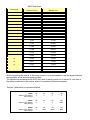
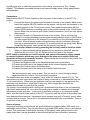
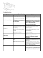
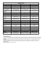
1000 Watt • 2500 Watt • 4500 Watt
PURE SINE WAVE INVERTER
1000 Watt • 2500 Watt • 4500 Watt
ONDULEUR À ONDE SINUSOÏDALE PURE
1000 Watt • 2500 Watt • 4500 Watt
INVERSORES ONDA SINUSOIDAL PURA
Models / Modèles / Modelos: 11240; 11260; 11264
12 Volt DC to 110-120 Volt AC
1000/2500/4500 Watt Continuous Output
2000/5000/9000 Watt High Surge Capacity
De 12 volts CC à 110-120 volts CA
Puissance continue de 1000/2500/4500 watts
Puissance de pointe 2000/5000/9000 watts
De 12 V CC a 110-120 V CA
1000/2500/4500 W Potencia Continua de salida
2000/5000/9000 W Potencia pico
User’s Manual
Notice D’utilisation
Manual del Usario
Thank you for choosing Sunforce Products Pro Series Pure Sine Wave Inverters. Our inverters
have been carefully engineered and manufactured to give you a dependable power source. A
Pure Sine Wave Inverter converts low voltage, direct current (DC) to 110 volt alternating
household current (AC) depending on the model and its rated capacity. Pure Sine Wave Inverters
draw power, either from standard 12 volt automobile and marine batteries, or from portable high
power 12 volt sources.
Please read this manual thoroughly before operating your new Inverter. Pay close attention to
any WARNING and CAUTION notes. This will help you to receive the best possible performance
from your new inverter.
1.
2.
3.
4.
5.
6.
7.
8.
9.
10.
11.
12.
Important Safety Precautions
Important Cable Information
About the Circuit Breaker
Full Load AC Output
Getting Started
Features of the Sunforce Products Pro Series Pure Sine Wave Inverter
Connecting your Inverter
Source of Power
While in Use
Remote Control
LCD Display
Trouble Shooting
IMPORTANT SAFETY PRECAUTIONS
Working with Batteries
• RISK OF EXPLOSIVE GAS – Working in the vicinity of a lead acid battery is dangerous.
Lead acid batteries produce hydrogen-gas when charging that can cause explosion and
sulfuric acid that can cause severe burns. Always charge batteries and work in a wellventilated area.
• DO NOT SMOKE, OR ALLOW A SPARK OR A FLAME IN THE VICINITY OF A
BATTERY!
• Remove personal metal items such as rings, necklaces, watches, and bracelets when
working with a battery. Be extra cautious not to drop a metal wrench onto the battery,
bridging the terminal posts. The battery may spark and short circuit, and explode.
• Be careful when making connections not to bridge the terminals with a wrench at the rear
of the inverters as the terminal posts are close to one another, and could result in a short
circuit.
• NEVER CHARGE A FROZEN BATTERY
• If battery acid contacts skin or clothing, wash immediately with soap and water. If acid
enters the eye, IMMEDIATELY FLOOD EYE WITH RUNNING COLD WATER for at least
10 minutes. GET MEDICAL ATTENTION IMMEDIATELY.
Failure to comply with above warnings may lead to explosion, and or severe injury.
Is the Battery Fully Charged?
State of battery can be determined by Hygrometer testing of electrolite in the battery, or the
voltage of the battery as measured with no load and a good quality digital voltmeter
See the table below
State of Charge Specific Gravity
Voltage
12V
6V
100%
1.265
12.7 6.3
*75%
1.225
12.4 6.2
50%
1.190
12.2 6.1
25%
1.155
12.0 6.0
Discharged
1.120
11.9 6.0
Working with Inverters
• Do not expose the inverter to moisture, including rain, snow, spray mist, or excessive
humidity. To reduce risk of fire hazard, do not cover or obstruct the ventilation openings.
Do not install the inverter in a non-ventilated space. Overheating may result.
• Use appropriate cables and attachments. To avoid a risk of fire and electric shock, make
sure that existing wiring is in good electrical condition; and that wire size is not undersized.
Do not use damaged or low grade wires. To ensure adherence to proper electrical wiring
regulations all wiring must be done by a certified technician or electrician.
Respect guidelines for the capacity of their inverter and recommended wire gage to be used.
Do not use inverter if it has been dropped or damaged.
• Do not attempt to repair or disassemble the inverter. Risk of shock and fire. Any
alterations to the inverter will render the warranty void.
• Disconnect the inverter from all connections before performing any maintenance on any of
the equipment, such as changing a fuse on the inverter.
• The inverter must be grounded. Grounding and all other wiring must comply with local
codes and ordinances. Grounding may be made to the chassis of most vehicles or to an
earth ground. Make sure the inverter is off before attempting to ground. Operating an
inverter that is not properly grounded may result in electrical shock.
• Reverse polarity connection will result in a blown fuse and may cause permanent damage
to the inverter and will void warranty
Making the 12V connections to the Inverter Terminals may cause a spark as a result of
current flowing to charge capacitors within the inverter. This is a normal occurrence. Due
to the possibility of sparking, however, it is extremely important that both the inverter and
the 12 volt battery be positioned far from any possible source of flammable fumes or
gases. Failure to heed this warning could result in fire or explosion.
• Be careful if you are hooking up the inverter to a battery just off the charger
• The battery is most likely the source of flammable gas. Gas from the battery is produced
during charging.
• Battery and/or inverter terminals may be hot if the unit has been operated at full capacity,
or has tripped from an overload. Caution when touching or servicing these connections.
• This is not a toy-keep away from children.
Circuit Breaker
The AC outlets are controlled by the Circuit Breaker. This device will shut the power off
automatically when the AC output is over limit, this may occur to all AC outlets or only one single
AC outlet. The Inverter can be turned on again after the AC plugs have been removed from the
AC Outlets and push the circuit breaker reset button(s).
•
IMPORTANT CABLE INFORMATION
Significant power loss to the inverter can occur from battery cables of insufficient gauge and or
excessive length when operating the units at their rated capacity. Marine installations are also
subjected to vibration and stresses that exceed those of other mobile installations. Therefore, the
installer/operator should take extra care to maintain secure, tight, water-resistant electrical
connections and to provide for strain relief for DC cables and appliance wiring. Cable insulation
must be the appropriate type for the environment.
About the Circuit Breaker
The AC outlets are controlled by circuit breakers. The full output is across all the AC outlets and
not accessible from a single AC outlet (or set of two AC outlets for model 11260; 11264). The
inverter will shut down in the event of overload on one AC outlet (or set of two AC outlets for
model 11260; 11264). The inverter may be turned on again once the load has been removed
and the circuit breaker button has been pushed to reset it.
Full Load AC Output
The total full loaded AC Output is the rated continuous output. The connector is live when the
power button is in the “ON” position. On models with multiple 110V outlets, the total output of the
unit is shared between the outlets. One outlet may not be able to deliver the total rated power on
the unit. Capacity of each plug outlet will be limited by the breaker on the outlet.
Features of the Sunforce Products Pro Series Pure Sine Wave Inverter
The output of the Pure Sine Wave Inverter provides stable power and it can be used to run the
electronic equipment that modified sine wave inverters cannot.
For example, the Pure Sine Wave Power Inverter works with small electronic tools, air pumps,
electronic doors, small motors, refrigerators and hair dryers.
This Inverter is configured with the latest Soft-Start Technology. Before introduction of Soft-Start,
high startup currents from large inductive loads could shut down the inverter. Soft Start improves
inverter operation. Three major features incorporated in SST include:
First, gradual voltage ramp-up during inverter startup. This eliminates failed cold starts under
load.
Second, output that momentarily dips in voltage and quickly recovers to allow large motorized
loads to start. This eliminates almost all shutdowns from momentary overloads.
Third, the inverter automatically re-starts when an overload that causes inverter shutdown is
removed. Previously, manual reset was required.
This inverter is equipped with the additional following safety features:
Low battery shutdown
DC Input overload voltage
Output overload
Overload temperature
Short circuit shutdown
Getting Started
Before installing and using the Sunforce Products Pro Series Pure Sine Wave Inverter please
read all instructions and cautionary markings on the inverter, batteries and all appropriate section
of this manual.
When you turn on an appliance, or a tool that operates using a motor or a tube (such as a
television), it requires an initial surge of power to start up. This surge of power is referred to as
the “starting load" or "peak load". Once started, the tool or appliance requires less power to
continue to operate. This is referred to as the “continuous load" in terms of power requirements.
You will need to determine how much power your tool or appliance requires to start up (starting
load) and it's continued running power requirements (continuous load). Power consumption is
rated in wattage (watts), or in amperes (amps), and this information is usually stamped on most
appliances and equipment. If this information is not indicated on the appliance or equipment,
check the owner's manual or contact the manufacturer to determine if the device you are using is
compatible with the Pure Sine Wave Inverter.
Calculating Loads (Wattage)
To calculate your continuous load when given in Amps:
Multiply: AMPS X 110(AC voltage) =WATTS
This formula yields a close approximation of the continuous load of your appliance.
To calculate approximate starting load:
Multiply: WATTS X 2= Starting Load
This formula yields a close approximation of the starting load of most appliances. However some
appliances can have a start up load of up to 7 times their continuous load. These are usually
tools and appliances using an induction motor, some examples are air conditioners, refrigerators,
well pumps and air compressors.
In most cases the start up load of the appliance or power tool determines whether your Inverter
has the capability to power it.
To determine whether the Sunforce Products Pro Series Pure Sine Wave will operate a particular
piece of equipment or appliance, it is advisable to run a test. All Pure Sine Wave inverters are
designed to automatically shut down in the event of a power overload. This protection feature
prevents damage to the unit while testing appliances and equipment with ratings in the correct
wattage range. If an appliance in the correct wattage range will not operate properly when first
connected to the Inverter, turn the Inverter rocker switch ON (I), OFF (O), and ON (I) again in
quick succession. If his procedure is not successful, it is likely that the inverter does not have the
required capacity to operate the appliance in question. (This approach is useful with a load that
may have a large internal capacitor (a TV for example) and the initial power draw is large enough
to trip the unit, but repeated restarting of the unit lets the capacitor/s in the load get charged a
little more each time, and then finally it will get past the big initial demand and will be able to run
the unit.
Connecting Your Inverter
Electrical connections
All contact joints MUST be clean in order to achieve low voltage loss due to contact resistance.
The lead posts on the battery should be cleaned with a terminal cleaner, a wire brush, or sand
paper. The posts should have a shiny finish when properly cleaned. The cable connectors should
be in the same clean state before hook up. Failure to do this will result in hotter then normal
electrical contacts and greater voltage loss to the inverter.
Wiring Specifications
AWG (American Wire Gauge) is a standard for wire sizes. The table below shows the properties
of a few of the sizes. For reference a 110v 1500W Toaster will have a power cord that is Gauge
16 size. For the same 1500W in a 12 Volt wire would need to be Gauge 1. 12 Volt source will
always require a larger diameter wire to deliver the same power as a 110V source would.
AWG Wire Sizes
AWG gauge
Conductor
Diameter Inches
Conductor
Diameter mm
OOOO
0.46
11.684
OOO
0.4096
10.40384
OO
0.3648
9.26592
0
0.3249
8.25246
1
0.2893
7.34822
2
0.2576
6.54304
3
0.2294
5.82676
4
0.2043
5.18922
5
0.1819
4.62026
6
0.162
4.1148
7
0.1443
3.66522
8
0.1285
3.2639
9
0.1144
2.90576
10
0.1019
2.58826
11
0.0907
2.30378
12
0.0808
2.05232
13
0.072
1.8288
14
0.0641
1.62814
15
0.0571
1.45034
16
0.0508
1.29032
When connecting the inverter to the power source, it is recommended to use the largest diameter
wire available in the shortest length possible.
The table below recommends the AWG Wire size for each inverter not to exceed .2 volts loss in
the cables connected to the inverter when it is operated at Maximum capacity.
See the Table below for recommendations
1000w
distance from battery
AWG Gauge
2ft
4
4ft
4
6ft
3
10ft
0
2500w
distance from battery
AWG Gauge
2ft
3
4ft
1
6ft
Ο
10ft
0000
4500w
distance from battery
AWG Gauge
2ft
1
4ft
0000
6ft
00000
10ft
N/R
Use #0 gauge wire to make the connections to the Inverter, may require a "0 to 4 Gauge
Adapter". This adapter is available through most electrical supply stores. Heavy gauge cables
sold separately
Connections
Make sure the ON/OFF Switch located on the front panel of the Inverter is in the OFF (O)
position.
1.
Connect the wires to the power input terminals at the rear of the Inverter. Make sure to
match the negative (BLACK) terminal on the Inverter, with the wire that connects to the
negative terminal on the 12 volt power source. Then repeat this procedure with the
positive (RED) terminal, connecting a wire to the positive terminal of the 12 volt power
source. Make sure you have a good (clean), secure connection, but do not over tighten
these screws.
2.
Locate the Ground Lug Terminal at the rear of the Inverter. Run a wire from this
terminal to a proper grounding point using the shortest practical length of 8 AWG wire.
You can connect this wire to the chassis of your vehicle or to the grounding system in
your boat. When in remote locations the ground wire can be connected to the earth
(one way to accomplish this is to attach it to a metal rod driven into the ground). Before
connecting the ground, make certain that the Inverter is turned off.
Operating the Inverter without correctly grounding the unit may result in electrical shock.
3.
When you have confirmed that the appliance to be operated is turned off, plug the
appliance into one of the 110V AC Outlets on the front panel of the inverter.
NOTE Loose connections can result in sparks, and a severe decrease in voltage caused
by contact resistance which may cause damage to the wires and insulation from heat
generation at the poorly contacted terminal. When making the connection to the inverter, the
following sequence is recommended.
1) Connect the Negative cable to the Negative terminal post on the battery.
2) Connect the other end of the Negative cable to the Inverter Negative terminal.
3) Connect the Positive cable to the battery post.
4) Connect the other end of the cable to the inverter Positive terminal.
This last connection may cause a spark. This is a result of current flowing to charge
capacitors within the Inverter. This is a normal occurrence.
The audible alarm may make a momentary "chirp" when the Inverter is turned OFF (O). This
same alarm may also sound when the Inverter is being connected to, or disconnected from the
12 volt power source. When using an extension cord from the Inverters to the appliance, the
extension cord should be no more than 50 feet long. At this length there should be no
measurable decrease in power from the inverter.
The inverter comes equipped with a cooling fan. An automatic shut down of the unit caused by
high circuit temperatures, will occur when the cooling fan is unable to maintain a cool enough
temperature for safe operation. In the event of automatic shut down or a continuous audible
alarm, turn the inverter power switch to the OFF (O) position until the source of the problem has
been determined and resolved. Inexpensive sound systems may emit a "buzzing" sound, when
operated with an Inverter. This is due to the inadequate filters within the sound system. There is
no solution to this problem.
Source of power
Automotive and Deep cycle batteries are good at delivering moderate power (300 watts) for a
reasonable period of time. They can also deliver High power (5000 watts), but for a short period
of time. This is because of the internal chemistry of the battery (water gets produced on the
plates faster then it can be absorbed in the electrolyte and acts as an insulator, increasing
internal resistance and reducing battery output). For continuous high power use, a bank of
batteries is certainly required.
Most automobile and marine batteries will provide an ample power supply to the inverter for 30 to
60 minutes, even when the engine is turned off. Actual time may vary depending on the age and
condition of the battery and the power demand being placed on it by the equipment being
operated.
The inverter can be used off an automobile battery while the engine is running. If you decide to
use the inverter while the engine is off, we recommend that you start the engine every 30 to 60
minutes and let it run for approximately 10 minutes to recharge the battery. This of course is
dependent on how much power you demand from the inverter. If the inverter shuts down by its
self due to battery depletion, you may not be able to start the car. It is also recommended that the
device plugged into the inverter be turned OFF before starting the vehicle engine. Although it is
not necessary to disconnect the inverter when starting the vehicle engine, it may momentarily
cease to operate as the battery voltage decreases. When the inverter is not supplying power it
draws very low amperage from the battery.
Never attempt to operate the Sunforce Products Pro Series Pure Sine Wave Inverter from any
power source other than a 12 volt battery. The inverter is not to be used in conjunction with 6 volt
or 24 volt batteries.
To maximize the performance of this product we recommend using multiple 12 volt deep
cycle batteries.
NOTE Always ensure the power cable terminal connections run Negative (-) to Negative (-) and
Positive (+) to Positive (+). Check these connections frequently to make sure they remain
secure. Use the heaviest gauge wire to connect the Inverter to the power source.
While connecting the Inverter to the power source, make certain that the Inverter is
positioned far away from any potential source of flammable fumes or gases.
While in use, make sure the inverter is properly ventilated. Ideal air temperatures should
be between 50ºF (10ºC) and 80ºF (26ºC).
Always ground the Inverter before operating it.
Make certain the power consumption of the appliance or equipment you wish to operate is
compatible with the capacity of the inverter. Do not exceed recommended wattage
limitations.
While in Use
When attempting to operate solar battery chargers, monitor the temperature of the battery
charger for approximately 10 minutes. If the battery charger becomes abnormally warm,
disconnect it from the inverter immediately.
In the event of a continuous audible alarm or automatic shutdown, turn the Inverter OFF
immediately. Do not restart the Inverter until the source of the problem has been identified and
corrected.
To avoid battery drain, always disconnect the Inverter when not in use.
Do not expose the inverter to rain or moisture and keep it dry. Water and other liquids can
conduct electricity, which may lead to serious injury.
Improper use of the inverter may result in property damage, or personal injury.
For best operating results, place the inverter on a flat surface.
Although all Sunforce Products Pro Series Pure Sine Wave Inverters are shielded and filtered to
minimize signal interference, some interference with your television picture may be unavoidable,
especially with weak signals.
Remote Control
A wireless remote control enables the inverter to be turned on at the touch of a button.
The remote control is included with your inverter and located on a keychain. To use the remote
control the receiver must first be plugged in to the inverter. The receiver box is attached to a cord
that can be plugged into a jack on the face of the inverter near the AC Outlets.
In the event the remote control is lost, disconnect the Remote Control Receiver from the inverter
by unplugging the cord from the jack.
The remote control is operational within 30 feet (9 meters) in open space.
The full-loaded Output Terminal is sharing the total output wattage capacity with the other
AC Outlets.
Therefore, the full-loaded output will be less than rated maximum output wattage when the
other AC Outlets are working.
LCD Display.
FAULT status – Future Protection.
1. Short Circuit Protection. The Inverter will automatically shut down until the short is removed.
2. Low Voltage Alarm. An alarm will sound when the voltage from the battery discharges, to
10.5+/-0.5 volts DC. This is an indication that the battery needs to be recharged.
3. Over Voltage Protection. The LED will illuminate RED and the Inverter will automatically turn
itself off, when the input exceeds16.5 +/-1 volt DC
4. Under Voltage Protection. The LED will illuminate RED and the Inverter will automatically turn
itself off, when the input is less than 10.0 +- 0.5 volts DC.
5. Overload Protection. The LED will illuminate RED and the Inverter will automatically turn itself
off, when the continuous draw of the equipment being operated exceeds rated capacity. Or the
surge draw of the equipment exceeds rated capacity watts.
6. Thermal Protection. The LED will illuminate RED and the Inverter will automatically turn itself
off when the circuit temperature exceeds 150°F. (65°C)
VDC
Press “SET” key to light up the Green LED beneath VDC.
The Input Voltage Level from the battery will be shown on the panel.
Example: 12.5V Input.
KW
Press “SET” key to light up the Green LED beneath KW.
The Power Consumption Load will be shown on the panel.
Example 1: 2500W Output
Example 2: 1380W Output
VAC
Press “SET” key to light up the Green LED beneath VAC.
The Output AC Voltage Level will be shown on the panel.
Example: AC 120V Output
Abnormal Display
1. Over Temperature
2. AC Overload or Shortage
3. Battery Voltage Too Low
4. Battery Voltage Too High
5. Inverter Defective
Normal Display
Voltage Reading Example
Trouble Shooting
Problem
Trouble Shooting
Reason
Battery voltage may be low.
Poor contacts are causing voltage
drop.
Low or No Output Voltage
Using incorrect type of voltmeter to
test output voltage.
Battery voltage below 10 volts.
Solution
Recharge or replace battery. May be
necessary to use two batteries to run some
items.
Unplug and reattach connections, may be
necessary to use shorter or heavier cables.
Check condition of 12 volt plug and socket,
clean or replace as necessary.
Use a true RMS reading meter.
Recharge or replace battery.
AC appliance consumption is higher Use a higher capacity inverter or lower
than capacity.
capacity appliance.
Fault LED on
TV Interference
Inverter is too hot causing thermal
overload.
Shut off inverter to allow cooling. Ensure
proper ventilation.
Inverter may be defective
Electrical interference from the
inverter
Contact tech hotline.
Use a filter in the TV power cord
Adjust placement of the television.
TV signal is too weak
Try another TV, different makes and
models may not experience the same
interference.
Recharge or replace battery. May be
necessary to use additional batteries to run
some items.
Low Battery Alarm on ALL the Input voltage below 10.5 VDC ± .5
time
VDC.
Poor contacts are causing voltage
drop.
Appliance not functioning
Appliance won't turn on.
Unplug and reattach connections, may be
necessary to use shorter or heavier cables.
Check condition of 12 volt plug and socket,
clean or replace as necessary.
Turn inverter ON, OFF, then ON again.
Contact manufacturer of appliance to check
start up power consumption and if product
is compatible with a modified sine wave
inverter.
Specifications
OUTPUT POWER
Continuous
Surge power
BATTERY DC INPUT
12V DC system
1000 Watt
2500 Watt
4500 Watt
1000 Watt
2000 Watt
2500 Watt
5000 Watt
4500 Watt
9000 Watt
12V DC nominal
(11-15V) operative
12V DC nominal
(11-15V) operative
12V DC nominal
(11-15V) operative
INVERTER AC
OUTPUT
Voltage
110V AC RMS +/-10%
110V AC RMS +/-10%
110V AC RMS +/-10%
Frequency
60Hz +/-2%
60Hz +/-2%
60Hz +/-2%
Wave form
Pure Sine Wave
Pure Sine Wave
Pure Sine Wave
Efficiency
90%
90%
90%
Total Harmonic
4% +/- 1%
4% +/- 1%
4% +/- 1%
Distortion
Output Voltage
110VAC +/- 10%
110VAC +/- 10%
110VAC +/- 10%
Variation
Frequency Variation
60Hz +/-2%
60Hz +/-2%
60Hz +/-2%
Total KVA (+/- 10%)
1.4
3.5
6.36
PROTECTION
Soft-start system
Yes
Yes
Yes
Low battery shutdown
Yes
Yes
Yes
DC Input overload
Yes
Yes
Yes
voltage
Output overload
Yes
Yes
Yes
Overload temperature
Yes
Yes
Yes
Short circuit shutdown
Yes
Yes
Yes
PHYSICAL
Yes
Yes
Yes
Ventilation
High Speed Cooling Fan High Speed Cooling Fan High Speed Cooling Fan
Weight
9.68 lbs (4.4 Kg )
18.73 lbs (8.496 kg)
25lbs (11.34 kg)
13.66 x 8.94 x 3.46 inches 13.96 x 6.69 x 9.19 inches 18.5 x 7.5 x 16 inches
Dimensions
(35 x 23 x 9cm)
(35.5 x 17 x 23.3cm)
(47 x 18 x 40.5cm)
LIMITED WARRANTY:
This product is covered by a two year limited warranty. Sunforce Products Inc warrants to the original purchaser that
this product is functional and free from defects in materials and workmanship for the period of two year from date of
purchase.
To obtain warranty service please contact Sunforce Products for further instruction, at 1-888-478-6435 or email
[email protected]. Proof of purchase including date, and an explanation of complaint is required for
warranty service.
Nickel iron batteries do not work with this inverter.