1
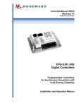
USER MANUAL
PRODUCT: DPG-2201-001
DYNA Programmable Governor for Isochronous Generators
With Load Sharing Capability
GOVERNOR OVERVIEW
The DPG-2201-001 is used primarily to govern
diesel or gas fueled engines of generator sets.
This microprocessor based, digital controller
performs across a wide speed range and allows
adjustment of all governor features through the
built-in user interface.
Separately programmable Proportional, Integral,
and Derivative gains are provided for tailoring
governor response to many engine applications.
Properly tuned, this governor delivers fast
engine response to speed or load change while
providing precise stable isochronous operation.
Other adjustments include Acceleration and
Deceleration Ramp Rates, Startup and Torque
Limits, Idle Speed Set and Hold Time, and
more.
This governor can also provide droop speed
control with 100 user selectable droop levels.
Isochronous Speed Control
Load Sharing & Droop Operation
User Friendly/Operator Adjustable
The governor’s internal FAILSAFE reacts
instantly to loss of the engine speed signal
allowing the actuator to return to minimum fuel.
.25% Precision Frequency Control
Superior Temperature Stability
Actuator
Compatibility:
Other Models
Available:
DYNA 326
DYNA 2000
DYNA 2500
DYNA 7000
DYNA 70025
Power Flow Gas Valves
DYNA 8000
DYNA 8200
DYNA 8400
DPG-2100 Series – for Genset Applications
DPG-2300 Series – for Off-road Vehicles
DPG-2401 Series – for EFC Valve Applications
DPG-2420 Series – for Pneumatic Actuators
Barber-Colman
DYNA Products
P.O. Box 2940
1354 Clifford Avenue
Loves Park, IL 61132
USA
Tel: (815) 637-3000
Fax: (815) 877-0150
www.dynaproducts.com
Reverse Battery Protection
9 - 30 VDC Input Voltage Range
Smoke Control on Start Up
Remote Setup
Serial Communication Port
DYNA 326
DPG-2201-001 User Manual
Page 2
WARNING: Always disconnect power before making external connections to the control unit, to
protect against electrical shock.
WARNING: As a safety measure, the engine should be equipped with an independent over speed
shutdown device in the event of a failure that may render the governor inoperative.
NOTE: Barber-Colman DYNA Products believes that all information provided herein is correct and
reliable but reserves the right to update at any time. Barber-Colman does not assume any responsibility
for its use unless otherwise expressly undertaken.
Table of Contents
USER MANUAL............................................................................................................................................................................ 1
1
GOVERNOR SPECIFICATIONS .................................................................................................................................. 4
1.1
1.2
1.3
2
USER INTERFACE OPERATION ................................................................................................................................ 5
2.1
2.2
2.3
3
ELECTRICAL .....................................................................................................................................................................4
M ECHANICAL...................................................................................................................................................................4
PERFORMANCE .................................................................................................................................................................4
OPERATING M ODES.........................................................................................................................................................5
KEYPAD ............................................................................................................................................................................6
LED DISPLAY ..................................................................................................................................................................7
PARAMETER REFERENCE........................................................................................................................................... 8
3.1
3.2
3.3
3.4
3.5
3.6
3.7
3.8
3.9
3.10
3.11
3.12
3.13
3.14
3.15
3.16
3.17
3.18
# OF FLYWHEEL TEETH (OPTIONAL).............................................................................................................................9
SET SPEED A(REQUIRED) ...............................................................................................................................................9
SET SPEED B (OPTIONAL).............................................................................................................................................10
IDLE SPEED (OPTIONAL ) ...............................................................................................................................................10
PROPORTIONAL (REQUIRED)........................................................................................................................................10
INTEGRAL (REQUIRED )..................................................................................................................................................11
DERIVATIVE (REQUIRED) .............................................................................................................................................11
OVG @ SET SPEED A (REQUIRED) ............................................................................................................................11
OVG @ SET SPEED B (OPTIONAL).............................................................................................................................11
OVG @ IDLE SPEED (OPTIONAL ) ...............................................................................................................................11
GAIN FACTOR (REQUIRED)...........................................................................................................................................12
SPEED FILTER (REQUIRED )...........................................................................................................................................12
IDLE HOLD TIME (OPTIONAL )......................................................................................................................................12
A CCEL RATE (OPTIONAL).............................................................................................................................................12
DECEL RATE (OPTIONAL ).............................................................................................................................................13
STARTUP RATE (OPTIONAL).........................................................................................................................................13
STARTUP LIMIT (OPTIONAL ) ........................................................................................................................................14
TORQUE LIMIT (OPTIONAL )..........................................................................................................................................14
© Copyright 2000-2003 Invensys. All Rights Reserved
DYNA 326
3.19
3.20
3.21
3.22
3.23
3.24
3.25
3.26
3.27
3.28
3.29
3.30
3.31
3.32
4
UNIVERSAL PST FEATURES.........................................................................................................................................18
UNIVERSAL PST REQUIREMENTS...............................................................................................................................18
A CQUIRING UNIVERSAL PST.......................................................................................................................................18
W IRING THE COMM PORT TO A PC...........................................................................................................................18
BASIC A DJUSTMENTS....................................................................................................................................................19
TUNING M ETHODOLOGY ..............................................................................................................................................19
DROOP CALIBRATION PROCEDURE .............................................................................................................................20
INSTALLATION INSTRUCTIONS ............................................................................................................................20
6.1
6.2
7
INTEGRAL LOW LIMIT (OPTIONAL ).............................................................................................................................14
INTEGRAL HIGH LIMIT (OPTIONAL)............................................................................................................................14
PERCENT DROOP (OPTIONAL )......................................................................................................................................15
NO LOAD CALIBRATION (OPTIONAL).........................................................................................................................15
FULL LOAD CALIBRATION (OPTIONAL )......................................................................................................................16
PASSWORD (OPTIONAL )................................................................................................................................................16
OVER SPEED LIMIT (OPTIONAL )..................................................................................................................................16
SET SPEED A MIN (OPTIONAL )....................................................................................................................................17
SET SPEED A MAX (OPTIONAL) ..................................................................................................................................17
SET SPEED B MIN (OPTIONAL)....................................................................................................................................17
SET SPEED B MAX (OPTIONAL)...................................................................................................................................17
IDLE SPEED M IN (OPTIONAL ).......................................................................................................................................17
IDLE SPEED M AX (OPTIONAL ) .....................................................................................................................................17
DUTYCYCLE M AXIMUM (OPTIONAL )..........................................................................................................................17
CALIBRATION INSTRUCTIONS...............................................................................................................................19
5.1
5.2
5.3
6
Page 3
UNIVERSAL PST (PARAMETER SETUP TOOL)................................................................................................18
4.1
4.2
4.3
4.4
5
DPG-2201-001 User Manual
TERMINAL DESCRIPTIONS............................................................................................................................................20
W IRING DIAGRAM.........................................................................................................................................................21
DIAGNOSTICS & TROUBLESHOOTING...............................................................................................................22
7.1
7.2
DISPLAY CODES.............................................................................................................................................................22
TROUBLESHOOTING TABLE .........................................................................................................................................22
DPG-2201-001 INSTALLATION RECORD & PARAMETER QUICK REFERENCE........................................24
© Copyright 2000-2003 Invensys. All Rights Reserved
DYNA 326
1
DPG-2201-001 User Manual
Page 4
Governor Specifications
The governor’s main electrical and mechanical specifications are listed here along with several performance
characteristics.
1.1
Electrical
Operating Voltages:
Maximum Controlled Output Current:
Maximum Surge Current:
Connections:
Input Signal from the Magnetic Pickup:
1.2
Mechanical
Ambient Operating Temperature:
Sealing:
Weight:
Connection
Mechanical Vibration
1.3
9 VDC minimum to 30 VDC maximum
7 amps
14 amps for ten seconds
Terminal Strip with 13 terminals
2.0 VAC RMS minimum during cranking
-40°F to +185°F, -40°C to +85°C
Oil, water, and dust resistant via conformal
coating and die cast enclosure
.75lbs, .34kilograms
13-terminal Euro-style connector
Suitable for mounting per SAE J1455;
1 to 500 Hz, 5G amplitude
Performance
Temperature Stability
Steady State Speed Band:
Engine Speed Measurement Range:
Governing Speed Range:
ILS Input Voltage Measurement Range:
ILS Input Speed Adjust Range:
Droop Adjustment Range:
Droop Setting Resolution:
0.007 Hz @ 70ºC
± .25% over Ambient Operating Temperature
range
10 MPU Hertz to 14,000 MPU Hertz
500 MPU Hertz to 11,000 MPU Hertz
2.4 VDC to 2.6 VDC
±3% around the set speed
0 to 10 percent of the set speed
Tenths of a percent
© Copyright 2000-2003 Invensys. All Rights Reserved
DYNA 326
2
DPG-2201-001 User Manual
Page 5
User Interface Operation
The user interface has two distinct behaviors that you should familiarize yourself with in order to select parameters
and make adjustments to them. These behaviors are described in the Operating Modes section below.
A 4-pushbutton keypad and a 2-digit LED display make up the built-in user interface. The pushbuttons, also called
keys, are described in the section named Keypad. The LED display is described in the section named LED Display.
Remote access to the governor’s parameter settings is available when the governor’s COMM port is connected to a
computer running our Universal PST application. The DPG-2201-001 Technical Manual, available from the website
www.dynaproducts.com, provides more information regarding the COMM Port and the Universal PST application.
2.1
Operating Modes
The user interface operates in two modes: PARAMETER SELECT MODE and PARAMETER EDIT MODE. For
each of these modes, the keypad and the display have a unique way of operating.
The following table provides a quick reference to the behavior of the display and the function of each key when a
particular operating mode is active.
PARAMETER SELECT MODE
LED Display
The ID number of a parameter
listed on the governor’s label is
blinking on and off
INC key
DEC key
SELECT key
ENTER
INC & DEC
Simultaneously
Increase the parameter ID number
by one
Decrease the parameter ID number
by one
Activate PARAMETER EDIT
MODE on the parameter whose
number was blinking
Display the version number of the
governor’s programming
Turn on all LED segments as a test
LED Display
INC key
PARAMETER EDIT MODE
The value of the selected parameter is
displayed. A blinking decimal point means the
value can be modified, otherwise the value is
view only.
Increase the selected parameter’s value.
DEC key
Decrease the selected parameter’s value.
SELECT key
Return to PARAMETER SELECT MODE and
ignore changes made to the parameter’s value
ENTER
Save the parameter’s new value, and return to
PARAMETER SELECT MODE
Use to display the upper digits of values larger
than 99
INC & DEC
Simultaneously
PARAMETER SELECT MODE is the mode used to select a parameter for viewing and editing. This mode is active
when the 2-digit value being displayed is blinking. The value being displayed is a parameter’s identification (ID)
number. The controller’s label lists each user-adjustable parameter and its corresponding ID number.
PARAMETER EDIT MODE is the mode that displays the selected parameter’s value and allows the value to be
modified. This mode is active when the 2-digit value being displayed is on and no longer blinking. The value being
displayed is the selected parameter’s current value. The display’s decimal points have several different meanings
while in PARAMETER EDIT MODE. These are described below.
•
Decimal point blinking - the selected parameter’s value can be modified.
•
Decimal point not blinking - the selected parameter’s value cannot be modified; parameter editing is
locked and values can only be viewed. This is the case when password protection is active and the
unlock code has not been entered. Read about the Password parameter in the Parameter Reference
chapter for more information about using password protection.
© Copyright 2000-2003 Invensys. All Rights Reserved
DYNA 326
2.2
DPG-2201-001 User Manual
Page 6
•
Right digit’s decimal point is blinking or on - the lower two digits (the tens digit and the ones digit) of
a parameter’s 4-digit value are being displayed.
•
Left digit’s decimal point is on - the upper two digits (the thousands digit and the hundreds digit) of a
parameter’s 4-digit value are being displayed. The upper two digits of a parameter are always view
only and can never be modified directly. The upper two digits change when the lower digits overflow
(transition from 99 to 00) or underflow (transition from 00 to 99).
Keypad
The keypad consists of four pushbuttons named ENTER, SELECT, INC, and DEC.
The ENTER key
The ENTER key is used to exit PARAMETER EDIT MODE and return to PARAMETER SELECT MODE while
saving the parameter’s new value to nonvolatile memory. Nonvolatile memory is where parameter values are stored
so that they are remembered even when the governor is not being powered. In PARAMETER SELECT MODE,
pressing ENTER displays the version number of the governor’s programming.
The SELECT key
The SELECT key is used to enter PARAMETER EDIT MODE from PARAMETER SELECT MODE once a
particular parameter has been selected for editing.
The SELECT key is also used to escape from PARAMETER EDIT MODE and return to PARAMETER SELECT
MODE without saving a change in a parameter’s value. The value a parameter had when PARAMETER EDIT
MODE was entered is restored.
The INC (increase) key
The INC key is used to increase the displayed value.
In PARAMETER SELECT MODE, each press of the INC key will cause the next higher parameter identification
number to be displayed. When the maximum parameter identification number is reached, the next INC key press
will cause the first parameter ID number to be displayed.
For example: If the controller’s label lists 32 parameters, then pressing the INC key when the display is
blinking the value 32 will cause the display to wrap around to the first parameter listed and begin blinking
the value 01.
In PARAMETER EDIT MODE, each INC key press will increase a parameter’s current value. If the INC key is
held down, while in PARAMETER EDIT MODE, the value will automatically continue to be increased at gradually
faster and faster rates until the INC key is released or the parameter’s maximum allowed value is reached. When the
lower two digits display a 99, pressing the INC (increase key) will cause the lower two digits to display a 00 and the
hundreds digit will have been increased by 1.
The DEC (decrease) key
The DEC (decrease) key is used to decrease the displayed value.
In PARAMETER SELECT MODE, each press of the DEC key will cause the next lower parameter number to be
displayed. When the first parameter identification number is reached, the next DEC key press will cause the last
parameter ID number to be displayed.
© Copyright 2000-2003 Invensys. All Rights Reserved
DYNA 326
DPG-2201-001 User Manual
Page 7
For example: If the controller’s label lists 32 parameters, then pressing the DEC key when the display is
blinking the value 01 will cause the display to wrap around to the last parameter listed, which in this case is
32, and blink this new value.
In PARAMETER EDIT MODE, each DEC key press will decrease a parameter’s current value. If the DEC key is
held down, while in PARAMETER EDIT MODE, the value will automatically continue to be decreased at gradually
faster and faster rates until the DEC key is released or the parameter’s minimum allowed value is reached. When the
lower two digits display a 00, pressing the DEC (decrease key) will cause the lower two digits to display a 99 and
the hundreds digit will have been decreased by 1.
The INC and DEC keys
In PARAMETER EDIT MODE, the INC and DEC keys are used together to view the value of the upper two digits
of a 4-digit number.
Press and hold both INC and DEC simultaneously to view the value of a 4-digit number’s upper two digits;
note that the left digit’s decimal point is turned on to indicate that the thousands and the hundreds digits are
being displayed.
Release INC and DEC and now the tens and the ones digits are again being displayed; note that the right
digit’s decimal point is blinking if editing is allowed or just on if editing is not allowed.
Note – not all parameters are 4-digit numbers, in which case the upper digits will always display 0.0 (zero dot zero).
In PARAMETER SELECT MODE, pressing both the INC and DEC keys at the same time will cause all LED
segments to be turned on. This serves as an LED test. Release the keys to resume displaying the parameter ID
number.
2.3
LED Display
The two 7-segment LED’s along with each digit’s corresponding decimal point are used to display values and
indicate the operating mode of the user interface.
When the value being displayed by the two 7-segment LED’s is blinking, PARAMETER SELECT MODE is active.
When the value being displayed is not blinking, the selected parameter’s value is being displayed and the user
interface is in PARAMETER EDIT MODE. The decimal points further indicate which half of a 4-digit value is
being displayed and whether editing is allowed.
The right digit’s decimal point is used to indicate that the lower 2 digits of a value (the tens and the ones digits) are
being displayed. When the right decimal point is blinking, it means that the value can be modified using the INC key
or the DEC key. Not blinking means that editing is not allowed or password protected.
The left digit’s decimal point is used to indicate that the upper 2 digits of a value (the thousands and the hundreds
digits) are being displayed. The upper 2 digits are always view only so the right decimal point does not blink.
Changes to the upper digits occur when a parameter’s lower digits overflow or underflow during editing.
An overflow occurs when the value 99 is being displayed and the INC key is pressed (assuming this is not the
parameter’s maximum value). This will cause the displayed value to become 00 while the non-displayed value in the
parameter’s upper 2 digits will be increased by one. You can verify this by pressing both INC and DEC at the same
time to view the new value in the upper digits. For example: If the full 4-digit value of the parameter you are editing
is currently 1099, then after pressing the INC key the parameter’s new value will be 1100.
An underflow occurs when the value 00 is being displayed and the DEC key is pressed (assuming this is not the
parameter’s minimum value). This will cause the displayed value to become 99 while the non-displayed value in the
© Copyright 2000-2003 Invensys. All Rights Reserved
DYNA 326
DPG-2201-001 User Manual
Page 8
parameter’s upper 2 digits will be decreased by one. You can verify this by pressing both INC and DEC at the same
time to view the new value in the upper digits. For example: If the full 4-digit value of the parameter you are editing
is currently 1800, then after pressing the DEC key the parameter’s new value will be 1799.
When values exceeding 9,999 are to be displayed, the controller uses the
hexadecimal numbering system to represent the value of the thousands
position.
Example 1: The desired set speed is 10,069 Hertz. The upper two digits
displayed by the controller will be [A.0], and the lower 2 digits displayed
will be [69.].
Example 2: The desired set speed is 10,972 Hertz. The upper two digits
displayed by the controller will be [A.9] and the lower 2 digits displayed
will be [72.].
3
Decimal to Hexadecimal
Conversion Chart
Decimal
Hexadecimal
Value
Equivalent
10
A
11
B
12
C
13
D
14
E
15
F
Parameter Reference
This chapter provides information
regarding each parameter’s function. It
contains 32 subsections. Each subsection
provides information about a single
parameter.
Subsection numbering corresponds to the
parameter numbering on the governor’s
label to make it easier to locate
information about the parameter of
interest. For example: Parameter 5.
PROPORTIONAL is described in
subsection 3.5 (chapter 3 subsection 5).
The table to the right lists each of the
parameters and their default, minimum,
and maximum values.
Note that several of the parameters have
minimum and maximum values set by
other parameters.
Note also that all Speed and Rate values
are shown as magnetic pick-up Hertz
values (parameters 2-4, 14-16, 26-31).
Changing the # of Flywheel Teeth will
cause different default values to be
displayed based on the Hertz to RPM
formula described is subsection 3.1
below.
DPG-2201-001 Parameter List
Parameter Name
Default
Minimum
Maximum
1. # of Flywheel Teeth
0
0
572
2. Set Speed A
1000
Set Speed A Min
Set Speed A Max
3. Set Speed B
1000
Set Speed B Min
Set Speed B Max
4. Idle Speed
500
Idle Speed Min
Idle Speed Max
5. Proportional
25
1
99
6. Integral
50
0
99
7. Derivative
25
0
99
8. OVG @ Set Speed A
20
1
99
9. OVG @ Set Speed B
20
1
99
10. OVG @ Idle Speed
20
1
99
11. Gain Factor
20
1
99
12. Speed Filter
16
1
24
13. Idle Hold Time
0
0
9999
14. Accel Rate
1000
1
11000
15. Decel Rate
1000
1
11000
16. Startup Rate
1000
1
11000
17. Startup Limit
1000
0
1000
18. Torque Limit
1000
0
1000
19. Integral Low Limit
0
0
Integral High Limit
20. Integral High Limit
99
Integral Low Limit
99
21. % Droop
0
0
100
22. No Load Cal
0
0
1000
23. Full Load Cal
1000
0
1000
24. Password
0
0
99
25. Overspeed Limit
100
0
100
26. Set Speed A Min
10
10
Set Speed A
27. Set Speed A Max
11000
Set Speed A
11000
28. Set Speed B Min
10
10
Set Speed A
29. Set Speed B Max
11000
Set Speed B
11000
30. Idle Speed Min
10
10
Idle Speed
31. Idle Speed Max
11000
Idle Speed
11000
32. Dutycycle Max
95
10
95
Parameters 2, 5, 6, 7, 8, 11, and 12 require adjustment, while adjustments to the
other parameters are optional.
© Copyright 2000-2003 Invensys. All Rights Reserved
DYNA 326
3.1
DPG-2201-001 User Manual
Page 9
# of Flywheel Teeth (optional)
This parameter provides the conversion factor needed by the governor to display speeds as RPM values instead of
Hertz values. Adjusting this parameter is optional. To use this parameter correctly, you must know the exact number
of flywheel teeth that pass by the magnetic pickup in one revolution of the engine.
The default value of 0 disables Hz to RPM conversions so all set speeds are displayed in MPU (magnetic pick-up)
Hertz. Setting this parameter to a value other than zero enables Hz to RPM conversion.
Adjust this parameter to a value equal to the exact number of pulses that the MPU delivers to the governor in one
revolution of the engine to display set speeds in RPM. The formula used to convert the magnetic pickup signal from
a Hertz value to a RPM value is:
[( MpuHertz ) × (60 s )] = [EngineRPM ]
[NumberOfTeeth]
For example:
[(3960 Hz ) × (60s )] = [1800 RPM ]
[132Teeth]
The following derivation of the above formula can be used to convert from RPM to Hertz.
[( EngineRPM ) × (NumberOfTeeth)] = [MpuHertz]
[60s ]
3.2
Set Speed A(required)
SET SPEED A is the governor’s target speed when the SPEED SEL input (terminal 8) is open and the startup
sequence has completed. The startup sequence is complete when the target speed and the engine speed reach the set
speed.
When a two-position switch is connected between SPEED SEL and +5VDC OUT (terminal 13) then an open switch
selects SET SPEED A as the governor’s target speed. If the governor’s SPEED SEL input is not used then SET
SPEED A is automatically the active target speed after the startup sequence is completed.
The default value for SET SPEED A is 1000 MPU Hertz. SET SPEED A’s adjustable range extends from SET
SPEED A MIN (parameter 26) to SET SPEED A MAX (parameter 27).
When SET SPEED A values greater than 9999 are displayed, the left most digit uses the capital letter A to represent
10000 and uses the lower case letter b to represent 11000.
For example: If SET SPEED A is set to 10750, then the upper 2 digits will be displayed by the controller as [A.7]
and the lower 2 digits will display [50.]
NOTE: If # of Flywheel Teeth is used then Set Speed A will be displayed as RPM.
© Copyright 2000-2003 Invensys. All Rights Reserved
DYNA 326
3.3
DPG-2201-001 User Manual
Page 10
Set Speed B (optional)
SET SPEED B becomes the governor’s target speed when the SPEED SEL input (terminal 8) is at 5 volts potential
and the startup sequence is complete. See the chapter Installation Instructions for details about wiring in a switch
between SPEED SEL and +5VDC OUT (terminal 13) in order to use SET SPEED B.
When a two-position switch is connected between SPEED SEL and +5VDC OUT then a closed switch selects SET
SPEED B as the governor’s target speed.
The default value for SET SPEED B is 1000 MPU Hertz. SET SPEED B’s adjustable range extends from SET
SPEED B MIN (parameter 28) to SET SPEED B MAX (parameter 29).
When SET SPEED B values greater than 9999 are displayed, the left most digit uses the capital letter A to represent
10000 and uses the lower case letter b to represent 11000.
For example: If SET SPEED B is set to 11000, then the upper 2 digits will be displayed by the controller as [b.0]
and the lower 2 digits will display [00.]
NOTE: If the # of Flywheel Teeth parameter is used then Set Speed B will be displayed as RPM.
3.4
Idle Speed (optional)
IDLE SPEED is the governor’s target speed for the IDLE HOLD TIME (parameter 13) when the engine is started.
When the idle hold timer reaches zero, the target speed will be become either SET SPEED A or SET SPEED B
depending on the state of the SPEED SEL input terminal.
The default value for IDLE SPEED is 500 MPU Hertz. The IDLE SPEED can be set to any value between IDLE
SPEED MIN (parameter 30) and IDLE SPEED MAX (parameter 31).
NOTE: If the # of Flywheel Teeth parameter is used then Idle Speed will be displayed as RPM.
3.5
Proportional (required)
The proportional term is one of the interrelated PID terms that determine how well a DPG-2000 series controller
governs the engine’s speed. A speed change creates a speed error (the difference between the target speed and the
actual speed.) The proportional gain controls the governor output produced for a specific amount of speed error.
Saturation
a higher Proportional value
increases error response rate
Controller output (%)
100%
a lower Proportional value
decreases error response rate
50%
Proportional
response
Saturation
0%
(-)
0
(+)
Error (%)
Each error value produces a unique controller output value
© Copyright 2000-2003 Invensys. All Rights Reserved
DYNA 326
The integral term is one of the interrelated PID terms that
determine how well a DPG-2000 series controller governs
the engine’s speed. The integral gain sets how fast the
governor’s output changes in response to how long a
speed error exists. In other words: In a proportional-only
control with constant load, there will be a constant speed
error that inversely relates to the proportional gain of the
system. The integral operates to drive this error to zero.
The integral gain changes the rate at which the error is
driven to zero.
Integral response to constant error
Integral is needed to eliminate speed offsets due to
proportional gain and should never be left at zero. A zero
value is allowed but should only be used as a test when
seeking to find the best proportional and derivative values.
100%
larger
Integral
value
50%
smaller
Integral
value
0%
Time
Error
Time
Derivative (required)
The derivative term is one of the interrelated PID terms
that determine how well a DPG-2000 series controller
governs the engine’s speed. The derivative responds to the
rate of change in the speed error. This parameter is
primarily used to dampen very rapid oscillations resulting
from large speed changes. A critically damped tuning will
always require some derivative. A zero value is allowed
but should only be used as a test when seeking to find the
best proportional and integral values.
Controller output (%)
3.7
Page 11
Integral (required)
Controller output (%)
3.6
DPG-2201-001 User Manual
Derivative response to changes
in the rate of deceleration or the
rate of acceleration.
100%
50%
0%
Time
3.8
OVG @ Set Speed A (required)
Error
(+)
0
Time
(-)
This gain acts as the multiplier on the three PID terms
(proportional, integral, and derivative) when Set Speed A
is selected as the active target speed. This gain term is
adjustable from 01 to 99.
3.9
The error is sampled at regular intervals
When the "Rate of change" changes (red dot) the
Derivative's impact on controller output changes.
OVG @ Set Speed B (optional)
This gain acts as the multiplier on the three PID terms (proportional, integral, and derivative) when Set Speed B is
selected as the active target speed. This gain term is adjustable from 01 to 99.
3.10 OVG @ Idle Speed (optional)
This gain acts as the multiplier on the three PID terms (proportional, integral, derivative) when the Idle Speed is the
active target speed. The idle speed set point is active only during startup when the idle hold timer is running. This
gain term is adjustable from 01 to 99.
© Copyright 2000-2003 Invensys. All Rights Reserved
DYNA 326
DPG-2201-001 User Manual
Page 12
3.11 Gain Factor (required)
The gain factor parameter is used to obtain more range of adjustment from the PID terms. In other words, if any of
the PID terms or the Overall gain terms reach their adjustment limits then this value can be modified to provide for
more range of adjustment in the PID and OVG terms.
For example, if the PID terms are set to 90, 80, and 50 respectively and the Gain Factor is set to 20, then doubling
the Gain Factor by setting it to 40 allows the PID terms to be halved to 45, 40, and 25 respectively. These new
settings are equivalent to the previous settings with respect to the governor’s tuning response and now allow the PID
terms to be adjusted higher if needed.
3.12 Speed Filter (required)
This parameter indicates the number of flywheel teeth to use when computing an average engine speed and is used
to dampen out speed measurement variations that can make PID tuning difficult. But keep in mind the following.
• Too much filtering will slow down the governor’s response to speed changes.
• Too little filtering can make the governor overly sensitive and tuning difficult.
There is measurable acceleration and deceleration that occurs between cylinder firings. As a general rule, less
filtering is required the more engine cylinders there are. This is because the number of acceleration-deceleration
cycles increases and these oscillations will have lower amplitude. With more cylinders there is less time for the
engine speed to slow down before the next cylinder firing.
Rotational mass also affects the amount of speed signal filtering needed. The more rotational mass, the less filtering
is needed. The less rotational mass, the more filtering is needed.
Typically the value 24 works well on small 3 or 4 cylinder engines. A value of 16 is recommended for 6 or 8
cylinder engines. The following formula can also be used to derive a good starting point for the speed filter value for
a given engine application. Round the result to the nearest integer. The maximum value allowed is 24.
[(#_of_flywheel_teeth) / (#_of_engine_cylinders)] * 0.75 = speed_filter_value
3.13 Idle Hold Time (optional)
The idle hold time specifies how long, after starting, the engine is to stay at the idle speed before finishing the ramp
to the target speed. The time value has a resolution of 1 tenth of a second.
3.14 Accel Rate (optional)
This rate specifies how fast the governor should increase the engine’s speed when a new higher target speed is made
active. The parameter value is specified in MPU (magnetic pickup) Hz per second based on the following formula.
[(higher_speed_in_Hertz) – (lower_speed_in_Hertz)] / (ramp_time_in_seconds) = accel_rate_value
For example, suppose Set Speed A is 3300 Hertz and Set Speed B is 3960 Hertz. The governor is currently
controlling the engine at 3300 Hertz (Set Speed A), when Set Speed B becomes the active target speed. It is desired
that the new speed of 3960 be reached in precisely 2 seconds. The following formula determines the value needed
by Accel Rate to increase the engine speed from Set Speed A to Set Speed B in 2 seconds.
[(Set Speed B) – (Set Speed A)] / (N seconds) = accel_rate_value in Hertz per second
[3960 – 3300] / 2 = 330 Hertz per second
© Copyright 2000-2003 Invensys. All Rights Reserved
DYNA 326
DPG-2201-001 User Manual
Page 13
3.15 Decel Rate (optional)
The Decel Rate specifies how fast the governor should decrease the engine’s speed when a new lower target speed is
made active. The parameter value is specified in MPU (magnetic pickup) Hertz per second based on the following
formula.
[(higher_speed_in_Hertz) – (lower_speed_in_Hertz)] / (ramp_time_in_seconds) = decel_rate_value
For example, suppose Set Speed A is 4170 Hertz and Set Speed B is 3475 Hertz. The governor is currently
controlling the engine at 4170 Hertz (Set Speed A), when Set Speed B becomes the active target speed. It is desired
that the new speed of 3475 be reached in precisely 1.5 seconds. The following formula determines the value needed
by Decel Rate to decrease the engine speed from Set Speed A to Set Speed B in 1.5 seconds.
[(Set Speed A) – (Set Speed B)] / (N seconds) = decel_rate_value in Hertz per second
[4170 – 3475] / 1.5 = 463 Hertz per second
3.16 Startup Rate (optional)
This parameter is used to achieve a smooth controlled engine start. On diesel engines this feature is also useful for
minimizing exhaust smoke at startup. When used in combination with the Idle Speed and Idle Hold Time, a brief
warm-up cycle can be programmed.
The startup rate specifies how fast the governor should increase the engine speed when the engine is started. The
rate value indicates Hertz per second. The formula to use for determining a precise Startup Rate is shown below.
[(final_target_speed_in_Hertz) – (crank_speed_in_Hertz)] / (ramp_time_in_seconds) = startup_rate_value
The governor increases the engine speed from the engine’s crank speed to the active target speed at the rate
specified. The governor will bring the engine to the Idle Speed for the Idle Hold Time then continue increasing the
engine speed at this same ramp rate until the engine reaches the selected target speed (Set Speed A or Set Speed B).
Exception 1 – In cases where the target speed is less then the Idle Speed and the Idle Hold Time is nonzero,
the startup ramp sequence ends when the Idle Speed is reached. Then the Decel Rate is used to ramp the
engine speed down to the target speed from the Idle Speed.
The ramp up will pause at 1000 MPU Hz until the governor senses an MPU signal greater than 1000 Hertz. This
prevents the startup ramp from reaching completion before the engine has even started. The governor considers
MPU frequencies below 1000 Hertz as indicating that the engine is cranking but has not yet started. MPU
frequencies above 1000 Hertz are taken to indicate that the engine has started and the governor will increase the
engine speed until the selected set speed is reached.
Exception 2 – In cases where the target speed is less the 1000 Hertz, the startup ramp sequence ends when
the target speed is reached.
NOTE:
When the # of FLYWHEEL TEETH parameter is used the ACCEL RATE, DECEL RATE, and STARTUP RATE
parameters are displayed as a RPM quantity per second instead of Hz/sec values. The given rate formulas can be
used to compute rates in terms of RPM values by substituting the Hertz speed values with RPM speed values.
© Copyright 2000-2003 Invensys. All Rights Reserved
DYNA 326
DPG-2201-001 User Manual
Page 14
3.17 Startup Limit (optional)
The startup limit parameter is used to limit the fuel supplied to the engine during startup. The default value of 1000
means that the actuator drive signal is allowed to use 100.0% of available current. Decreasing the value limits the
available drive signal thereby limiting how far open the actuator can go. Increasing the value allows the actuator to
open further.
The value assigned to the startup limit parameter is in units of 1 tenth of a percent of the actuator’s maximum
current feedback reading. The governor measures actuator drive signal feedback to obtain an approximation of the
amperes of current flowing through the actuator. Fuel limiting is achieved by setting the maximum level of electrical
current allowed to flow through the actuator during engine startup. This feature is useful in reducing smoke when
starting diesel engines.
Note – If the value is set too low the engine may not start.
3.18 Torque Limit (optional)
The torque limit parameter is used to limit the fuel supplied to the engine during heavy generator loads or generator
overloads. The default value of 1000 means that the actuator drive signal is allowed to use 100.0% of available
current. Decreasing the value limits the available drive signal thereby limiting how far open the actuator can go.
Increasing the value allows the actuator to open further.
The value assigned to the torque limit parameter is in units of 1 tenth of a percent of the actuator’s maximum current
feedback reading. The governor measures actuator drive signal feedback to obtain an approximation of the amperes
of current flowing through the actuator. Fuel limiting is achieved by setting the maximum level of electrical current
allowed to flow through the actuator during normal operation.
Note – If the value is set too low the engine will not be able to carry its rated load.
3.19 Integral Low Limit (optional)
The integral low limit prevents "integral windup" in the negative direction. In other words, the integral low limit
parameter is used to reduce under speed duration after a long or sustained over speed condition was present. The low
limit helps reduce the duration and amount of engine under speed by maintaining a minimum actuator position.
When smaller PWM duty cycle values do not reduce the engine speed any further but an off speed (measured speed
greater than the target speed) remains, letting the Integral term grow more negative is not beneficial. Unused
negative integration would cause a slower recovery from an under speed condition.
The integral low limit specifies the PWM duty cycle where the integrator’s influence on lowering PID output must
stop. The default value is 0%. The value can be adjusted from 0% to 90% in 1% increments.
CAUTION: Use carefully, improper use can prevent the governor from ever reaching the target speed. The first line
of defense in reducing over speed or under speed errors is a well-tuned governor via the PID terms.
3.20 Integral High Limit (optional)
The integral high limit prevents "integral windup" in the positive direction. In other words, the integral high limit
parameter is used to reduce over speed duration after a long or sustained under speed condition was present. The
high limit helps reduce the duration and amount of engine over speed by maintaining a maximum actuator position.
© Copyright 2000-2003 Invensys. All Rights Reserved
DYNA 326
DPG-2201-001 User Manual
Page 15
When larger PWM duty cycle values do not increase the engine speed any further but a negative off speed
(measured speed less than the target speed) remains, letting the Integral term grow more positive is not beneficial.
Unused positive integration would cause a slower recovery from an over speed condition.
If an engine overload situation causes the engine speed to remain below the target speed for some period of time,
then the integral portion of PID output would grow larger than otherwise needed (would windup). So when the load
is removed the engine may over speed because it takes time for the integral portion of PID output to shrink or
“unwind”. This is where reducing the Integral Limit High value can help by preventing excessive windup in the PID
output’s integration term.
The integral high limit specifies the PWM duty cycle where the integrator’s influence on raising PID output must
stop. The default value is 99%. The value can be adjusted from 99% down to 10% in 1% increments.
CAUTION: Use carefully, improper use can prevent the governor from ever reaching the target speed. The first line
of defense in reducing over speed or under speed errors is a well-tuned governor via the PID terms.
3.21 Percent Droop (optional)
The percent droop parameter is used to select droop mode operation and specify the percentage of droop required.
When the percent droop parameter is set to zero (the default setting) then droop mode is not active. Droop mode is
active when this parameter is set to any value from 1 to 100 which corresponds to 0.1% to 10.0% droop.
The following formula determines the no load droop speed.
[(selected_set_speed) / ((1000 – value_of_%_DROOP) / 1000)] = no_load_droop_speed
For example: If 5% droop is desired, set the percent droop value to 50. Now if the selected set speed is 1800 RPM
then the no load droop speed will be:
[(1800RPM) / ((1000 – 50) / 1000)] = 1800RPM / 0.95 = 1895RPM
NOTE: This parameter can only be modified during the Droop Calibration Procedure. See the Calibration
Instructions chapter for more information.
Droop mode relies on knowing the actuator position. The actuator’s position corresponds to the amount of fuel being
delivered to the engine. The DPG-2201-001 controller senses electrical current flow through the actuator to
determine its position. This method of position sensing does not work with all actuators.
3.22 No Load Calibration (optional)
The No Load Calibration value is learned during the Droop Calibration Procedure and should not be set manually.
Once calibrated, the no load calibration value indicates the percentage of electrical current, relative to the
measurable maximum, that must flow through the actuator to run the engine at the no load droop speed.
The factory default value is zero, so if droop mode is to be used, this parameter must be calibrated. The no load
calibration value must be less than then the full load calibration value for proper droop operation. If after performing
the Droop Calibration Procedure the no load calibration value is greater than the full load calibration then the droop
function can not be used. Some actuators may have a current verses position curve that is incompatible with this
controller’s method of determining actuator position.
NOTE: This parameter is only modified during the Droop Calibration Procedure. See the Calibration Instructions
chapter for more information.
© Copyright 2000-2003 Invensys. All Rights Reserved
DYNA 326
DPG-2201-001 User Manual
Page 16
3.23 Full Load Calibration (optional)
The Full Load Calibration value is learned during the droop calibration procedure and should not be set manually.
Once calibrated, the full load calibration value indicates the percentage of electrical current, relative to the
measurable maximum, that must flow through the actuator to run the engine at the selected set speed when a full
load is being applied to the generator.
The factory default value is 1000, so if droop mode is to be used, this parameter must be calibrated. The full load
calibration value must be greater than the no load calibration value for proper droop operation. If after performing
the Droop Calibration Procedure the full load calibration value is less than the no load calibration value then the
droop function can not be used. Some actuators may have a current verses position curve that is incompatible with
this controller’s method of determining actuator position.
NOTE: This parameter is only modified during the Droop Calibration Procedure. See the Calibration Instructions
chapter for more information.
3.24 Password (optional)
The password protect parameter is provided to protect against inadvertent parameter changes that may occur
whenever the keys are pressed and a parameter modification is not intended. The password protect parameter has
three possible settings: DISABLED, LOCKED, and UNLOCKED
DISABLED – This setting turns off any password protection. Use this setting if password protection is not desired.
This is the default setting as shipped from the factory. Entering a value of [99] sets the password protect parameter
to the disabled mode. When the password protect parameter is selected, the LED display will show [Pd] for 2
seconds indicating the password disabled mode, then the value [00.] is displayed. The user can then edit the value.
LOCKED – This setting means that password protection is active and only parameter viewing is allowed (parameter
editing is disabled). Enter a value of [22] to set password protect to locked mode. For 2 seconds after selecting the
password protect parameter the LED display will show [PE.] for this mode and the rightmost decimal point will be
on (no blinking), then the value [00.] is displayed. The user can then edit the value.
UNLOCKED – This setting means that password protection is active but parameter editing is allowed. Entering a
value of [30] while in LOCKED mode will UNLOCK parameter editing. The user is free to edit parameters. If there
is no keypad activity for 5 minutes, the controller returns to LOCKED mode.
If not already in the UNLOCKED mode, the user must get into the UNLOCKED mode in order to enter a 99 to
disable password protection.
3.25 Over Speed Limit (optional)
This parameter is used to determine the engine speed that will trigger the governor to output minimum fuel. The
parameter’s value is in terms of a percentage over the highest set speed. In other words, an over speed condition is
detected if the engine speed reaches a speed of [OVER SPEED LIMIT %] greater than the highest set speed.
For example: If the highest set speed is 1800 RPM and this parameter is set to 20, then an over speed condition will
be detected at 2160 RPM (the value that is 20% greater than 1800). Formula: 1.20 * 1800 RPM = 2160 RPM
The default value of 100 is used to disable over speed detection. Use values less than 100 to enable the over speed
limit function and set the limit speed to [(1 + (overspeed_limit_value/100)) * (highest_set_speed)].
NOTE: The governor must be turned off to clear the over speed detection before the engine can be re-started.
© Copyright 2000-2003 Invensys. All Rights Reserved
DYNA 326
DPG-2201-001 User Manual
Page 17
NOTE:
When the # of FLYWHEEL TEETH parameter is used the SET SPEED A MIN, SET SPEED A MAX, SET
SPEED B MIN, SET SPEED B MAX, IDLE SPEED MIN, and IDLE SPEED MAX parameters are displayed as
RPM values instead of Hertz values.
3.26 Set Speed A Min (optional)
Set Speed A Min is used to set the lowest value allowed for Set Speed A adjustments. This parameter can be set to
any value within the range bordered by 10 Hertz (or its RPM equivalent) and the current value of the Set Speed A.
3.27 Set Speed A Max (optional)
Set Speed A Max is used to set the highest value allowed for adjustments of Set Speed A. This parameter can be set
to any value within the range bordered by current Set Speed A setting and 11,000 Hertz (or its RPM equivalent).
3.28 Set Speed B Min (optional)
Set Speed B Min is used to set the lowest value allowed for adjustments of Set Speed B. This parameter can be set to
any value within the range bordered by 10 Hertz (or its RPM equivalent) and the current value of Set Speed B.
3.29 Set Speed B Max (optional)
Set Speed B Max is used to set the highest value allowed for adjustments of Set Speed B. This parameter can be set
to any value within the range bordered by current Set Speed B setting and 11,000 Hertz (or its RPM equivalent).
3.30 Idle Speed Min (optional)
This parameter sets the minimum value that the Idle Speed parameter is allowed to have. This parameter can be set
to any value within the range bordered by current Idle Speed setting and 11,000 Hertz (or its RPM equivalent).
3.31 Idle Speed Max (optional)
This parameter sets the maximum value allowed for Set Speed A Max, Set Speed B Max, and Idle Speed.
3.32 Dutycycle Maximum (optional)
The Dutycycle Maximum parameter sets the absolute maximum amount of drive signal that can be output to the
actuator and thus serves as a mechanism for fuel limiting. Fuel limiting is achieved by setting the maximum
dutycycle or ontime allowed during one cycle of the PWM (pulse-width-modulation) signal controlling the actuator
drive circuit. The value assigned to the dutycycle limit parameter is a percentage, and is limited to values in the
range 10% to 95%. The default value is 95%.
© Copyright 2000-2003 Invensys. All Rights Reserved
DYNA 326
4
DPG-2201-001 User Manual
Page 18
Universal PST (Parameter Setup Tool)
The Universal PST is a Microsoft® Windows® application available from Barber-Colman DYNA Products
that enables you to adjust parameter settings and monitor governor operation when a PC is connected to the
governor through the built-in COMM port.
4.1
Universal PST Features
Universal PST for DPG features include:
• automatic configuration to each DPG when communications established
• read/write access to all of a DPG’s programmable parameters and features
• display of each parameter's default, minimum, and maximum values
• diagnostics utilizing automatic refresh of DPG status
• saving and reloading DPG setup information to and from a file for reuse
• single button read to get the current values of all parameters
• single button write to program a DPG with previously saved setup values
• engine speed monitoring via a chart recorder to aid in tuning the governor
• saving chart recorder data to a Microsoft Excel compatible file
• help information on each of the governor’s parameters
• help information on using the Universal PST
4.2
Universal PST Requirements
The program requires an Intel Pentium class machine running Microsoft® Windows® 98se, NT4, 2000, or
XP. The display resolution needs to be set to SVGA (800x600) or higher. The Universal PST program is not
supported on Microsoft® Windows® 95. The program may work on Microsoft® Windows® ME
(Millennium Edition), but this has not been tested.
4.3
Acquiring Universal PST
The Universal PST application is available to you at no additional cost for use with any COMM port
equipped DPG.
Downloading software via the internet
The files ReadMeFirst.txt and Universal_PST.zip are available for download on the software download
page at the www.dynaproducts.com website.
Requesting the Universal PST on CD-ROM
Contact the Barber-Colman DYNA Products sales department to request a CD-ROM copy of Universal
PST. Telephone: (815) 637-3000
4.4
Wiring the COMM Port to a PC
Wiring instructions are described in document number DYNA 316 available from the software download
page at www.dynaproducts.com
© Copyright 2000-2003 Invensys. All Rights Reserved
DYNA 326
5
5.1
DPG-2201-001 User Manual
Calibration Instructions
Basic Adjustments
The controller is programmed at the factory with default
parameter settings. These settings allow the controller to operate
but will usually require some further adjustments to obtain the
best system performance. In order to bring the engine up to a
single speed for the first time, the installer will probably need to
make adjustments to the parameters shown in the table.
The parameters listed in the table are the primary ones to modify
to get the governor tuned and the engine running smooth. It is
recommended that you work with them first and leave all the
other parameters at their default values until you are satisfied
with the basic engine tuning.
5.2
Page 19
ID#
2
5
6
7
8
11
12
Parameter Name
SET SPEED A
PROPORTIONAL
INTEGRAL
DERIVATIVE
OVG @ SET SPEED A
GAIN FACTOR (note 1)
SPEED FILTER (note 2)
Default Value
1000
25
50
25
20
20
16
Note 1: Modify Gain Factor only if you run out of
adjustment in a PID or OVG term.
Note 2: For the Speed Filter, typically the value 24
works well on small 3 or 4 cylinder engines. A value of
16 is recommended for 6 or 8 cylinder engines.
Tuning Methodology
Once the engine is running, the following procedure may be used to discover more optimum values for PID and the
overall gain (OVG) parameters. The goal would be to find PID values that allow the controller to govern the engine
well at a variety of different speeds and loads while only requiring gain adjustment at those different speeds.
The Derivative works on the
Instantaneous Rate of Change
in the amount of error
The Proportional
term's output is
unique for each
+E
Error
Step:
1. Set the integral and derivative terms to 0.
2. Set the overall gain low (<20).
3. Increase the proportional term until you get
continuous oscillations greater than 2Hz.
4. Reduce the proportional term by 25% to 50%.
5. Now experiment with small value changes in the
derivative to dampen out “ringing” in response to
load transients.
6. Add some integral to eliminate any steady-state
error in the engine’s speed and help decrease error
recovery time.
7. The overall gain can be increased to improve
response time while keeping the ratios of the PID
terms relative to each other constant.
measured error
0
Time
-E
Integration works on
the sum of the errors
accumulated over time
During each of the steps 3 through 6 you need to disturb the system by adding and removing a load from the engine
to check the governor’s response to the load transition. START WITH SMALL LOADS.
Note that without integral a speed error may persist after a load-on/load-off transition. So during steps 3-5 you
should temporarily increase the integral to get the engine speed back to the set speed, then reset the integral to a
lower value again while working to find good proportional and derivative values. Repeat steps 3-7 as needed to find
a Proportional value, Integral value, and a Derivative value that work well with a variety of overall gain values and
different load transients.
© Copyright 2000-2003 Invensys. All Rights Reserved
DYNA 326
5.3
DPG-2201-001 User Manual
Page 20
Droop Calibration Procedure
To use Droop, a calibration sequence must be done first.
The calibration sequence is as follows.
Step 1
Make sure the engine is running at the selected set speed and the governor is tuned.
Step 2
Enter a value of 41 into the Password parameter (#24) to allow editing of the droop related parameters.
Step 3
Select the “% DROOP” parameter (#21) and adjust its value while the engine is running with no load
applied. The engine speed will increase to:
[(selected_set_speed) / ((1000 – value_of_%_DROOP) / 1000)].
Step 4
Allow the engine to stabilize at the no load droop speed then press the controller’s ENTER key to set the
percent droop. No Load Calibration is now complete.
Step 5
Select the “FULL LOAD CAL” parameter (#23). The engine speed will return to the selected set speed.
Step 6
Now apply full load to the engine and allow the speed to stabilize.
Assumes the governor was previously tuned.
Step 7
Wait 5 seconds then press the controller’s ENTER key to record the calibration value.
Full Load Calibration is now complete.
Step 8
Remove the load from the engine. The engine speed will increase to the no load droop speed.
Droop Calibration is complete.
After droop calibration, the difference between the No Load Cal and Full Load Cal parameter value should be
greater than 100 for best operation of droop. The droop function may still work for smaller differences but with less
accuracy. You may be able to get some improvement by modifying or adjusting actuator linkage or adding springs.
The goal is to achieve a wider range of measured current change through the actuator from no load to full load.
If the calibrated range is too small then droop may not work at all. The actuator position sensing method used by this
controller does not work with all actuators. A different actuator may be required or a different system solution
altogether may be needed by your application, such as an actuator with a position feedback potentiometer and a
supporting controller.
6
6.1
Installation Instructions
Terminal Descriptions
#
1
2
3
4
5
6
7
8
9
10
11
12
13
Name
BAT+
BATACT
ACT
MPU+
MPUSHIELD
SPEED SEL
ILS SIGNAL
ILS REF (2.5V)
DEC SPEED
INC SPEED
+5VDC OUT
Function
Battery positive (Supply voltage range is 9VDC-30VDC)
Battery negative
Actuator Drive output
Actuator Drive return
Magnetic Pickup Signal Inputs
Magnetic Pickup ground
Ground connection for cable shielding
Digital Input used to select the target set speed
ILS input used to adjust speed +/- 3%
Supply voltage around which ILS operates
Digital Input used to decrease the selected set speed remotely
Digital Input used to increase the selected set speed remotely
Supply voltage for the digital inputs
© Copyright 2000-2003 Invensys. All Rights Reserved
DYNA 326
6.2
DPG-2201-001 User Manual
Wiring Diagram
For Terminal Descriptions, see the table on the previous page.
© Copyright 2000-2003 Invensys. All Rights Reserved
Page 21
DYNA 326
7
DPG-2201-001 User Manual
Page 22
Diagnostics & Troubleshooting
7.1
Display Codes
Code
E0
E1
E2
E3
7.2
Meaning
Controller memory failure. Replace controller.
Loss of remote speed potentiometer signal (applies only to DPG-2302-001s and DPG-2401-001s).
Overspeed detected. Controller must be turned off to reset the controller to allow an engine restart.
Actuator drive overcurrent detected. Check wiring. Check actuator loading.
Troubleshooting Table
SYMPTOM
REMEDY
LED Display Does Not Light Up
When Governor Is Powered
•
•
•
•
•
•
•
•
•
•
•
•
•
•
•
Unable to Modify Parameters
Engine Does Not Start
•
Engine Over Speeds at Startup
Engine Does Not Reach the Set
Speed
•
•
•
•
•
•
•
•
•
•
•
BAT + and BAT – leads are reversed. Check wiring.
Battery voltage too low. Should measure between 9 and 30 VDC
Controller is defective. Replace it.
The parameter’s value is at the maximum value allowed.
The parameter’s value is at the minimum value allowed.
A display code is active. Refer to the Display Codes section above
Password protection is enabled. Enter Password
Keypad Failure, replace unit.
Actuator leads not connected or shorted.
No Fuel Source. Turn on fuel source.
Battery voltage is low. Charge or replace the battery.
Set speed is lower than crank speed. Increase the set speed.
Startup Rate setting is too low. The target speed ramps up too slow.
Startup Limit is too low, limiting the actuator drive signal too much.
Is the MPU speed signal present? It should read 2.0VRMS minimum.
Adjust magnetic pickup (MPU) gap. Try reversing the MPU leads.
If a speed signal is present, measure actuator output duty cycle. If not
greater than 5%, then restore all parameter values to factory default
settings and crank the engine again.
Increase the Proportional value.
Increase the appropriate OVG (overall gain) value.
Use the Startup Limit.
Decrease the Startup Ramp Rate.
Improve PID tuning.
Integral too low or zero
Derivative too low or zero
PID values are too low. A tuning that is too soft can prevent the governor
from delivering the needed actuator drive signal to reach the set speed.
PID values are too high. Tuning is too hot or oversensitive to small speed
errors which causes the governor to make large rapid changes in actuator
drive signal which creates an average signal that is inadequate.
The Integral Low Limit setting is too high. Return the value to the default
setting of zero.
The Integral High Limit setting is too low. Return the value to the default
setting of 99.
© Copyright 2000-2003 Invensys. All Rights Reserved
DYNA 326
DPG-2201-001 User Manual
Page 23
Troubleshooting Table continued
SYMPTOM
REMEDY
Engine takes too long to reach the
set speed.
•
•
•
•
•
•
•
•
•
•
•
•
•
•
•
•
•
•
•
•
•
•
•
•
•
•
Engine Does Not Track Speed
Setting Changes
Excessive Smoke at Startup
Sluggish Response to load
changes
Engine Instability With No-load
Engine Instability With Load
Engine Unable to Carry Rated
Load
Load Sharing Does Not Work
•
•
•
•
•
•
Droop Does Not Work
•
•
•
•
Improve PID tuning.
Integral setting is too low.
Startup Rate setting is too low.
Accel Rate setting is too low.
Speed Filter setting is too high.
Is the LED decimal point blinking? If not enter password.
Is the selected set speed parameter being modified?
A PID value or an OVG value is too high.
A PID value is too low or zero.
Accel Rate is set too low.
Decel Rate is set too low.
Improve PID tuning.
Use a lower Startup Rate setting.
Use a lower Startup Limit setting.
Low MPU signal voltage. It should read 2.0VRMS minimum.
Gain too low.
Improve PID tuning.
Speed Filter setting is too high.
Improve PID tuning.
Speed Filter setting is too low.
Fuel is restricted. Check actuator linkage.
Battery voltage is too low.
Improve PID tuning.
Fuel is restricted. Check actuator linkage.
Battery voltage is too low.
PID values may be too high causing the governor to over react and make
large rapid changes in PWM duty cycle output to the actuator.
Improve PID tuning.
Torque Limit is set too low. Increase the Torque limit.
Fuel is restricted. Check actuator linkage.
Measure the ILS input signal to see if the measurement is between 2.375
and 2.625 volts DC.
Use shielded wiring
If the application requires more than ±3% of speed change around the set
speed then use a DPG-2401-001 controller instead.
The No Load and Full Load values are not calibrated. Perform the Droop
Calibration Procedure.
Difference between No Load and Full Load calibration values is too
small. Should be > 100 for best performance.
Modify or adjust actuator linkage to increase range of actuator loading.
If finer droop control is required, then use a DPG-2401-001 controller
instead.
© Copyright 2000-2003 Invensys. All Rights Reserved
DYNA 326
DPG-2201-001 User Manual
Page 24
DPG-2201-001 INSTALLATION RECORD & PARAMETER QUICK REFERENCE
Customer: ______________________________________________
Distributor: _____________________________________________
Installation Site: _________________________________________
Engine Information: ______________________________________
# of Cylinders: ______ Fuel Type:________
Magnetic Pickup: _____________________
Phone #: _ _________________________
Phone #: _ _________________________
Installation Date: ____________________
Actuator Model #: ___________________
Actuator Serial #: ___________________
DPG-2201-001 Serial #: ______________
DPG-2201-001 Software Version: ______
NOTES: ____________________________________________________________________________________
Record an installation’s DPG-2201-001 Setup Information in the User Setting column of the following table.
ID# PARAMETER NAME – parameter definition
Default
Value
0
1.
# OF FLYWHEEL TEETH - is a factor used to display speed as RPM instead of MPU Hertz values.
2.
SET SPEED A - is the governor’s target speed when the controller’s SPEED SEL terminal is open.
1000
3.
SET SPEED B - is the governor’s target speed when the SPEED SEL terminal is at 5 volts DC.
1000
4.
IDLE SPEED - is the governor’s target speed for the IDLE HOLD TIME when the engine first starts. If the
value of the IDLE HOLD TIME parameter is zero the IDLE SPEED is not used.
PROPORTIONAL - is the gain applied to the speed error.
INTEGRAL - is the gain on the reset time and is used to eliminate the speed offset due to proportional gain.
DERIVATIVE - is the gain on the response to the rate of speed change.
OVG @ SET SPEED A - is a multiplier used on the three PID terms when Set Speed A is the target speed.
OVG @ SET SPEED B - is a multiplier used on the three PID terms above when Set Speed B is the target.
OVG @ IDLE SPEED - is a multiplier used on the three PID terms above when Idle Speed is the target.
GAIN FACTOR - is a multiplier applied to the PID terms that can be used to give those terms more range.
SPEED FILTER - is the number of flywheel teeth to use when computing an average engine speed.
IDLE HOLD TIME - is the period of time that the engine will remain at the Idle Speed during the startup
sequence before ramping to either Set Speed A or Set Speed B.
ACCEL RATE - is the rate, in MPU Hertz (or RPM) per second, used to ramp to a new higher target speed.
DECEL RATE - is the rate, in MPU Hertz (or RPM) per second, used to ramp to a new lower target speed.
STARTUP RATE - is the rate in MPU Hertz (or RPM) per second at which the governor will ramp to the
selected target speed when the engine is started. Useful in limiting smoke at engine startup.
STARTUP LIMIT - is the maximum actuator current output allowed when starting the engine. Resolution
is 0.1%, so a value of 1000 means 100%. Use to limit smoke at engine startup.
TORQUE LIMIT - is the maximum actuator current output allowed during heavy generator load. The
resolution is 0.1%, so a value of 1000 means 100%.
INTEGRAL LOW LIM - is the duty cycle percentage where integration stops when the governor is trying
to decrease engine speed. It limits integral wind-down. Use with caution.
INTEGRAL HIGH LIM - is the duty cycle percentage used to limit integral windup when the governor is
trying to increase engine speed. Use with caution.
% DROOP - is the percentage of droop desired adjustable in steps of 0.1%. This means that a value of 99
represents 9.9% droop. The Droop Calibration Procedure must be used to modify this parameter.
NO LOAD CAL - is the calibrated actuator current needed to maintain the unloaded droop speed. This
parameter is set automatically during the Droop Calibration Procedure. The resolution is 0.1%.
FULL LOAD CAL - is the calibrated actuator current needed to maintain the selected target speed when the
engine is fully loaded. This parameter is set automatically during the Droop Calibration Procedure.
PASSWORD - is a key used to lock or unlock the capability to modify the parameter values.
It is also used to activate the droop calibration procedure.
OVERSPEED LIMIT - is the percent over the higher of Set Speed A or Set Speed B that will cause the
governor to output the minimum signal to the actuator.
SET SPEED A MIN - sets the lowest value allowed for Set Speed A’s adjustable range.
SET SPEED A MAX - sets the highest value allowed for Set Speed A’s adjustable range.
SET SPEED B MIN - sets the lowest value allowed for Set Speed B’s adjustable range.
SET SPEED B MAX - sets the highest value allowed for Set Speed B’s adjustable range.
IDLE SPEED MIN - is the lowest value allowed for the Idle Speed parameter.
IDLE SPEED MAX - is the highest value allowed for the Idle Speed parameter.
DUTYCYCLE MAX - sets the absolute maximum amount of drive signal that can be output to the actuator
and thus serves as a mechanism for fuel limiting. Adjustable in 1% steps.
500
5.
6.
7.
8.
9.
10.
11.
12.
13.
14.
15.
16.
17.
18.
19.
20.
21.
22.
23.
24.
25.
26.
27.
28.
29.
30.
31.
32.
© Copyright 2000-2003 Invensys. All Rights Reserved
25
50
25
20
20
20
20
16
0
1000
1000
1000
1000
1000
0
99
0
0
1000
0
100
10
11000
10
11000
10
11000
95
User
Setting