1
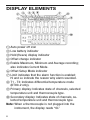
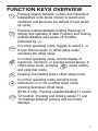
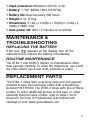
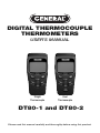
DIGITAL THERMOCOUPLE
THERMOMETERS
USER’S MANUAL
Single
Thermocouple
Dual
Thermocouple
DT80-1 and DT80-2
Please read this manual carefully and thoroughly before using this product.
TABLE OF CONTENTS
Introduction . . . . . . . . . . . . . . . . . . . . . . . . . . . . . . . . . 3
Key Features . . . . . . . . . . . . . . . . . . . . . . . . . . . . . . . . 4
Operating Instructions . . . . . . . . . . . . . . . . . . . . . . . . 5
Display Elements . . . . . . . . . . . . . . . . . . . . . . . . . . . . 6
Function Keys Overview . . . . . . . . . . . . . . . . . . . . . . . 7
Specific Operating Instructions . . . . . . . . . . . . . . 8 – 9
Specifications . . . . . . . . . . . . . . . . . . . . . . . . . . 10 – 11
Maintenance & Troubleshooting . . . . . . . . . . . . . . . . 11
Replacing the Battery . . . . . . . . . . . . . . . . . . . . . . . . 11
Routine Maintenance . . . . . . . . . . . . . . . . . . . . . . . . 11
Replacement Parts . . . . . . . . . . . . . . . . . . . . . . . . . . 11
Warranty Information . . . . . . . . . . . . . . . . . . . . . . . . 12
Return Policy . . . . . . . . . . . . . . . . . . . . . . . . . . . . . . . 13
Disposal . . . . . . . . . . . . . . . . . . . . . . . . . . . . . . . . . . . 13
2
INTRODUCTION
Thank you for purchasing a Thermocouple type J/K
digital thermometer from General Tools & Instruments.
We suggest that you read this user’s manual carefully
and thoroughly before using the instrument.
The DT80-1 and DT80-2 are thermocouple-type J/K
digital thermometers. The DT80-1 is designed to be used
with a single thermocouple; the DT80-2 is designed to be
fed by two thermocouples configured to deliver a
temperature differential.
Each model uses a high-resolution analog-to-digital
converter chip and a microprocessor to convert input
temperature signals to digital form and display them on
a dual-display, 5-digit black-and-white liquid crystal
display measuring 1.5 by 1.5 inches.
These two thermocouple thermometers have a
measurement accuracy of ±(0.05% of reading + 1.4°F)
with an unmatched measurement range. For example,
the DT80-1 and DT80-2 can measure and read out
temperatures from -328° to 1922°F (-200° to 1050°C)
using a J-type thermocouple, and temperatures from
-328° to 2498°F (-200° to 1370°C) using a K-type
thermocouple. This very wide measuring range, plus a fast
response time make these thermocouple thermometers
suitable for a wide range of commercial and industrial
applications requiring measurement of very high and low
temperatures. Examples include applications in the food
and chemical processing industries, HVAC (heating,
ventilation and air-conditioning), power generation, and
paper production.
3
Simplicity is another asset of thermocouple
thermometers. Thermocouples work by measuring the
potential difference produced at the junction of two wires
made of different metals but exposed to the same
temperature. Since the junction is very small, a
thermocouple thermometer can be used to measure the
temperature at a point reachable by a probe. The probes
used are inexpensive and easily replaceable.
KEY FEATURES
• Dual 5-digit liquid-crystal display
• Measurement range: -328° to 1922°F
(-200° to 1050°C) using a J-type thermocouple;
-328° to 2498°F (-200° to 1370°C)
using a K-type thermocouple
• Measurement accuracy:
±(0.05% of reading +1.4°F)
• Operating temperature range:
40° to 104°F (5° to 40°C)
• Power Source: 1 “9V” battery
4
OPERATING INSTRUCTIONS
Familiarize yourself with the nomenclature in the
following two illustrations before using the DT80-1 or
DT80-2.
BACK, FRONT AND TOP VIEWS
Thermocouple T1 input
Thermocouple T2 input (DT80-2 only)
Display (see next illustration)
Function keys
Battery cover
Battery compartment
5
DISPLAY ELEMENTS
Auto power off icon
Low battery indicator
Hold (freeze) display indicator
Offset change indicator
Enable Maximum, Minimum and Average recording;
also indicates Current Mode.
Offset Setup Mode indicator
Limit indicates that the alarm function is enabled;
Hi and Lo indicate the reason why alarm sounded.
T1 - T2: Indicates differential temperature mode
(DT80-2 only).
Primary display: Indicates state of channels, selected
temperature unit and thermocouple type.
Secondary display: Indicates state of channels, selected temperature unit and thermocouple type.
Note: When a thermocouple is not plugged into the
instrument, the display reads “OL”
6
FUNCTION KEYS OVERVIEW
ºC/
ºF
HO
LD
TYPE
X
MA IN
M
L
RE
Pressing toggles between Celsius and Fahrenheit
temperature units (scale chosen is saved upon
shutdown and becomes the default of next power
up cycle).
Pressing enables/disables holding (freezing) of
display and updating of data. Pressing and holding
enables/disables auto power off function
(indicated by ).
In normal operating mode, toggles to select J- or
K-type thermocouple. In offset setup mode,
increases the offset value.
In normal operating mode, selects display of
maximum, minimum, or average temperatures. In
offset setup mode, pressing MMAXIN saves setting
and exits that mode.
Pressing and holding enters offset setup mode.
In normal operating mode, pressing turns
O instrument on or off. In offset setup mode,
pressing decreases offset value.
T1-T2
T1➝T2
(DT80-2 only). Pressing enables/disables T1 minus
T2 function. Pressing and holding swaps T1 and
T2 readings between primary and secondary
displays.
7
➝
SPECIFIC OPERATING
INSTRUCTIONS
To display maximum, minimum or average
temperature, push the MMAXIN key repeatedly until the
corresponding icon appears above the reading in the
primary display. The primary display shows the current
channel reading of MAX, MIN or AVG. The secondary
display shows the current channel reading of actual
temperature. When the instrument powers off, the value
chosen is saved and becomes the default value for the
next power up cycle.
To select the thermocouple type, press the TYPE
key (in normal operating mode) until the correct letter
(K or J) appears on the left side of the primary display. In
the case of the DT80-2, use the T1T1-T2
➝T2 key to also set the
correct thermocouple type in the secondary display. Both
the DT80-1 and DT80-2 will save their setting(s) upon
shutdown and make them the default when they next
power up.
➝
To hold (freeze) the display and stop updating
measurements, press the HOLD key. Press it again to
unfreeze the display. When the HOLD function is enabled,
all function keys (except for the O key) are disabled.
Using the REL key to subtract readings. Pressing the
L
RE key cancels out a relative reading, changes the
display to “0” and saves the previous reading
as the standard relative reading. For example, if
the primary display is reading 25°C, pressing the
L
RE key changes the display to “0” and saves 25°C as
8
the standard relative reading. Then, if the temperature
rises to 30°C, the display will show 5°C (30° – 25°C).
If the temperature falls to 20°C, the display will show 5°C (20° – 25°C). Pressing the REL key again disables
this function and restores the actual temperature reading
to the display.
The primary display shows the current channel reading of
REL. The secondary display shows the current channel
reading of actual temperature.
In the case of the DT80-2, to show the current channel
reading of REL on the secondary display, press and hold
the T1T1-T2
➝T2 key to swap T1 and T2.
➝
To display T1 minus T2 temperature (DT80-2 only),
press the T1T1-T2
➝T2 key. Press the key again to disable this
function.
➝
The primary display shows the T1-T2 temperature. The
secondary display shows the current channel reading of
actual temperature. To swap channels, press and hold
the T1T1-T2
➝T2 key.
➝
To enable/disable the 15-minute Auto Power Off
function, press and hold the HOLD key (with the
instrument in normal operating mode) until the
appears or disappears at the upper left of the screen.
To power the instrument on and off, press the O key.
If pressing the key fails to shut off the unit, that means it
is in offset setup mode. Exit this mode by pressing the
O key, and then push the MMAXIN key again.
9
To compensate for thermocouple error, you must first
set the offset value. To do so (recommended each time
the thermocouple probe is changed):
1. Press and hold the
RE
L
key.
2. Use the TYPE and O keys, respectively, to increase
or decrease the offset value. The allowable adjustment
range is ±9°F (±5°C).
X
3. Press the MMAIN key to save the setting and exit offset
setup mode.
To adjust the offset of the secondary channel in the
DT80-2, press the T1T1-T2
➝T2 key and repeat steps 2 and 3.
➝
The instrument will automatically save the offset value
upon shutdown, and default to it upon the next startup.
SPECIFICATIONS
• Display: dual 5-digit LCD
• Temperature units: Degrees Celsius or Fahrenheit
• Display resolution: 0.1
• Measurement range: -328° to 1922°F (-200° to
1050°C) using a J-type thermocouple; -328° to 2498°F
(-200° to 1370°C) using a K-type thermocouple
• Measurement accuracy: ±(0.05% of reading + 1.4°F)
• Supplied Probe(s) Range: 50º to 500ºF (-45º to 260ºC)
• Operating temperature range: 40° to 104°F
(5° to 40°C), below 80% RH
• Storage temperature range: 14° to 140°F
(-10° to 60°C), below 70% RH
10
• Input protection: Maximum 24V DC or AC
• Battery: 1 “9V” (NEDA 1604, IEC 6F22)
• Battery life: Approximately 200 hours
• Weight: 6 oz. (170g)
• Dimensions: 5.12(L) x 2.2(W) x 1.50(H) in. (130(L) x
56(W) x 38(H) mm)
• Auto power off: after 15 minutes of no activity
MAINTENANCE &
TROUBLESHOOTING
REPLACING THE BATTERY
If the icon
appears on the display, turn off the
instrument and replace the battery immediately.
ROUTINE MAINTENANCE
The DT80-1 and DT80-2 require no maintenance other
than periodic cleaning. To clean the instrument, use a soft
dry cloth. Never use a wet cloth, solvents or water.
REPLACEMENT PARTS
The DT80-1 ships with a carrying case and one generalpurpose K-type thermocouple probe with a beaded tip
General P/N TPK500. The DT80-2 ships with two of these
probes. To order additional probes of this type, or other
specialty thermocouple probes, refer to page I-38 of
General’s Full Line or Professional Test Instruments
catalogs or visit www.generaltools.com.
11
WARRANTY INFORMATION
DT80-1 and DT80 Thermocouple type J/K from General
Tools & Instruments (General) is warranted to the original
purchaser to be free from defects in material and
workmanship. Subject to certain restrictions, General
will repair or replace this instrument if, after examination,
the company determines it to be defective in material
or workmanship. The warranty period begins on the
date of purchase. You are encouraged to register your
product online. General will extend your warranty an
additional 60 days if you register at
www.generaltools.com/ProductRegistry.
This warranty does not apply to damages that General
determines to be from an attempted repair by nonauthorized personnel or misuse, alterations, normal wear
and tear, or accidental damage. The defective unit must
be returned to General Tools & Instruments or to a
General-authorized service center, freight prepaid and
insured.
Acceptance of the exclusive repair and replacement
remedies described herein is a condition of the contract
for purchase of this product. In no event shall General be
liable for any incidental, special, consequential or punitive
damages, or for any cost, attorneys’ fees, expenses, or
losses alleged to be a consequence of damage due to
failure of, or defect in any product including, but not
limited to, any claims for loss of profits.
Register now at www.generaltools.com/ProductRegistry
to receive a 60-day extension to your warranty.
12
GENERAL’S RETURN FOR
REPAIR POLICY
Every effort has been made to provide you with a reliable,
product of superior quality. However, in the event your
instrument requires repair, please contact our Customer
Service to obtain a RGA# (Return Goods Authorization)
before forwarding the unit via prepaid freight to the
attention of our Service Center at this address:
General Tools & Instruments
80 White Street
New York, NY 10013
212-431-6100
Remember to include a copy of your proof of purchase,
your return address, and your phone number and/or email address.
The DT80-1 or DT80-2 are warranted to be free of
defects in materials and workmanship for one year after
the date of purchase.
This warranty applies to all repairable instruments that
have not been tampered with or damaged through
improper use, including unauthorized opening of the unit.
DISPOSAL
This symbol (on the rear of the case) indicates that the
DT80-1 and -2 contain materials that should be recycled
or disposed of correctly disposal, rather than
landfilled.
13
NOTES
14
NOTES
15
GENERAL TOOLS & INSTRUMENTS
80 White Street
New York, NY 10013-3567
PHONE (212) 431-6100
FAX (212) 431-6499
TOLL FREE (800) 697-8665
e-mail: [email protected]
www.generaltools.com
DT80-1 and DT80-2 User’s Manual
Specifications subject to change without notice
©2014 GENERAL TOOLS & INSTRUMENTS
NOTICE - WE ARE NOT RESPONSIBLE FOR
TYPOGRAPHICAL ERRORS.
MAN# DT80-1 and DT80-2
3/13/14