1
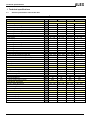
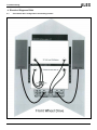
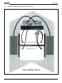
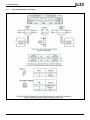
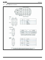
SERVICEMANUAL
ALEX
© 2010 Handicare
All rights reserved.
The information provided herein may not be reproduced and/or published in any form, by print, photo print, microfilm or any other means
whatsoever (electronically or mechanically) without the prior written authorization of Handicare.
The information provided is based on general data concerning the constructions known at the time of the publication of this manual. Handicare
executes a policy of continuous improvement and reserves the right to make changes and modifications.
The information provided is valid for the product in its standard version. Handicare cannot be held liable for possible damage resulting from
specifications of the product deviating from the standard configuration.
The available information has been prepared with all possible care, but Handicare cannot be held liable for possible errors in the information or
the consequences thereof.
Handicare accepts no liability for loss resulting from work executed by third parties.
In accordance with the legislation concerning the protection of trade names, all names and trade names, etc. used by Handicare may not be
considered as being available to others.
2010-01
2
Version 2010v2
Table of contents
1
2
3
4
5
Technical specifications
4
1.1 Product specification sheet of the Alex..........................................................................................................4
Maintenance
5
2.1 Maintenance table..........................................................................................................................................5
2.2 Batteries .........................................................................................................................................................5
Troubleshooting
6
3.1 R-Net faultfinding table ..................................................................................................................................6
Electrical Diagrams R-Net
10
4.1 Front wheel drive configuration and battery position. ..................................................................................10
4.2 Rear wheel drive configuration and battery position....................................................................................11
4.3 R-net Power Module connections................................................................................................................12
4.4 R-Net ISM Module connections ...................................................................................................................13
4.5 R-Net basic configuration ............................................................................................................................14
4.6 R-Net basic configuration ISM module without electrical lift........................................................................15
4.7 R-Net basic configuration ISM module with electrical lift.............................................................................16
Use of the parts lists
17
5.1 Sedeo ...........................................................................................................................................................19
5.2 Carrier ..........................................................................................................................................................37
5.3 Seat adjustments, wiring and modules ........................................................................................................45
Version 2010v2
3
Technical specifications
1 Technical specifications
1.1
Product specification sheet of the Alex
Manufacturer:
SPECIFICATIONS
DIMENSIONS
Axle configuration
Maximum user's weight
Batteries (C20)
Total weight excluding batteries (60Ah C20)
Total weight including batteries
Total length
Total width
Seat angle
Seating depth
Seat width
Seat height excluding cushion
Seat height including cushion
Back angle
Back height
Lower leg length
Armrest height
From front of armrest to back rest
Diameter of swivel wheels (Indoor)
Diameter of swivel wheels (Outdoor)
Diameters of drive wheels
Tyre pressure of swivel wheels
Tyre pressures of drive wheels
PERFORMANCE
Maximum speed
Range of action (ISO 7176-4)
Dynamic stability (max. safe slope)
Obstacle height
Obstacle height with curb climber
Ground clearance
Turning radius (ISO 7176-5)
ELECTRICAL OPTIONS
Electric back adjustment
Electric tilt adjustment
Electrical high/low
Electric leg rest adjustments
CERTIFICATES
CE
EN 12182 (1997)
EN 12184 (1999)
Classes
ISO 7176-19
4
®
Handicare
kg
Ah
kg
kg
mm
mm
°
mm
mm
mm
mm
°
mm
mm
mm
mm
mm
mm
mm
bar
bar
ALEX INDOOR / outdoor
FWD
RWD
160
160
60 / 74
60 / 74
87
87
130,6
130,6
1120
1080
610
610
0 – 7,5
0 – 7,5
440 - 520
440 - 520
380 - 555
380 - 555
400 – 47,5 400 – 47,5
470 - 545
470 - 545
89 - 118
89 - 118
520 - 570
520 - 570
330 - 560
330 - 560
220 - 290
220 - 290
370 - 450
370 - 450
225
225
325
325
2.0 bar
2.0 bar
2.7 bar
2.7 bar
ALEX OUTDOOR / indoor
FWD
RWD
160
160
60 / 74
60 / 74
87
87
130,6
130,6
1130
1090
640
640
0 – 7,5
0 – 7,5
440 - 520
440 - 520
380 - 555
380 - 555
41,5 - 490
41,5 – 490
48,5 - 560
48,5 - 560
89 - 118
89 – 118
520 - 570
520 - 570
330 - 560
330 - 560
220 - 290
220 - 290
370 - 450
370 - 450
255
255
350
350
2.5 bar
3.5 bar
3.5 bar
3.5 bar
km/h
km
°
mm
mm
mm
mm
6/9
50 (74Ah)
6 (10,5%)
60
70
660
6/9
50 (74Ah)
10 (17,5%)
60
100
70
910
6,5 / 10
6,5 / 10 / 12,5
50 (74 Ah)
50 (74 Ah)
6 (10,5%)
10 (17,5%)
75
75
115
85
85
660
910
°
°
mm
°
88 - 120
2,5 - 25
0 - 300
6 - 70
88 - 120
2,5 - 25
0 - 300
6 - 70
88 - 120
2,5 - 25
0 - 300
6 - 70
88 - 120
2,5 - 25
0 - 300
6 - 70
√
√
√
B
√
√
√
√
B
√
√
√
√
B
√
√
√
√
B
√
Version 2010v2
Troubleshooting
2 Maintenance
2.1
Maintenance table
Below, we have indicated what needs to be checked, how often this should be done, and by whom.
Time
Description
Daily
Weekly
Monthly
•
•
•
•
•
•
•
•
•
•
•
•
Annually
2.2
Charging the batteries, after each use.
Checking the tyre pressures.
Cleaning the wheelchair.
Cleaning the upholstery (if necessary).
Inspection of the electrical system.
Checking the batteries.
Inspection of the drive.
Inspection of the mechanical parts.
Inspection of the bearings.
Inspection of the suspension.
Checking the tyres.
Checking all fastenings and bolts: tighten if necessary.
To be carried out by
User
Dealer
X
X
X
X
X
X
X
X
X
X
X
X
Batteries
For maintenance, see the following documentation:
−
Regulations concerning the batteries.
−
User manual of the battery charger.
The wheelchair has 'dry' gel batteries. These dry batteries (dry-fit) are entirely sealed and maintenance free.
The connection diagram for the batteries is provided on a sticker inside the battery tray.
−
−
−
Version 2010v2
Make sure that the batteries are always well charged.
Do not use the wheelchair if the batteries are almost flat. This may damage the batteries and
you run the risk of an unintended standstill.
The use of 'wet' batteries is not permitted. If the batteries need to be replaced, use only dry
batteries.
5
Troubleshooting
3 Troubleshooting
3.1
R-Net faultfinding table
Trip Text
Joystick Error
-
Low Battery
-
High Battery
-
M1 Brake Error
1505
M2 Brake Error
1506
M1 Motor Error
3B00
M2 Motor Error
3C00
Inhibit Active
1E01
1E09
1E0A
Joystick Calibration Error
6
Trip Code
-
Description
The most common cause of this trip is if the joystick is deflected away
from center before and during the time the control system
is switched on. The joystick displaced screen will be displayed for 5
seconds, if the joystick is not released within that time then a
trip is registered. Although a trip screen is not displayed the system log
will show the trip and numbers of occurrences.
• Ensure that the joystick is centered and power-up the control system.
If the trip is still present then the joystick or Joystick Module may be
defective.
This occurs when the control system detects that the battery voltage has
fallen below 16V.
• Check the condition of the batteries and the connections to the control
system.
If the trip is still present after the batteries and connections have been
checked, then the Power Module may be defective.
This occurs when the control system detects that the battery voltage has
risen above 35V. The most common reasons for this are
overcharging of the battery or bad connections between the control
system and the batteries.
• Check the condition of the batteries and the connections to the control
system.
If the trip is still present after the batteries and connections have been
checked, then the Power Module may be defective.
This occurs when the control system detects a problem in the solenoid
brakes or the connections to them.
• Check the solenoid brakes, cables and connections to the control
system.
If the trip is still present after the above checks have been made, then the
Power Module may be defective.
This occurs when the control system detects a problem in the solenoid
brakes or the connections to them.
• Check the solenoid brakes, cables and connections to the control
system.
If the trip is still present after the above checks have been made, then the
Power Module may be defective.
This occurs when the control system detects that a motor has become
disconnected.
• Check the motors, cables and connections to the control system.
If the trip is still present after the above checks have been made, then the
Power Module may be defective.
This occurs when the control system detects that a motor has become
disconnected.
• Check the motors, cables and connections to the control system.
If the trip is still present after the above checks have been made, then the
Power Module may be defective.
This occurs when any of the Inhibit inputs are active and in a latched
state.
The actual inhibit that is active is indicated by the last 2 digits in the Trip
Code.
• Cycle the power. This will drop out of Latched Mode which might clear
the trip.
• Check all wiring and switches connected to the indicated Inhibits.
If the trip is still present after the above checks have been made, then the
ISM may be defective.
This occurs when the Joystick Calibration process has not been
successful.
• Enter OBP and attempt calibration.
If the trip is still present after the above has been attempted, then the
Joystick Module may be defective.
Version 2010v2
Troubleshooting
Trip Text
Trip Code
Latched Timeout
-
Brake Lamp Short
-
Left Lamp Short
7205
Right Lamp Short
7209
Left Indicator Lamp Short
7206
Right Indicator Lamp
Short
720A
Left Indicator Lamp
Failed
7207
Right Indicator Lamp
Failed
7208
Over Current
-
Overtemp. (Actuators)
-
Version 2010v2
Description
This occurs when the control system detects that the Latched Timeout
programmed time has been exceeded. For example, the
Input Device, Joystick, Head Aray, Sip and Puff, etc.) has not been
operated frequently enough.
The trip is a notification of why the control system has dropped out of
Latched Mode.
• Cycle the power.
• Initiate Latched Mode.
If the trip is still present after the above checks have been made, then the
Input Device may be defective.
This occurs when the control system detects a short in the Brake Lamp
Circuit.
• Check the brake lamps, cables and connections to the control system.
If the trip is still present after the above checks have been made, then the
ISM may be defective.
This occurs when the control system detects a short in either of the Lamp
Circuits.
• Check the lamps, cables and connections to the control system.
If the trip is still present after the above checks have been made, then the
ISM may be defective.
This occurs when the control system detects a short in either of the Lamp
Circuits.
• Check the lamps, cables and connections to the control system.
If the trip is still present after the above checks have been made, then the
ISM may be defective.
This occurs when the control system detects a short in either of the
Indicator Circuits.
• Check the indicators, cables and connections to the control system.
If the trip is still present after the above checks have been made, then the
ISM may be defective.
This occurs when the control system detects a short in either of the
Indicator Circuits.
• Check the indicators, cables and connections to the control system.
If the trip is still present after the above checks have been made, then the
ISM may be defective.
This occurs when the control system detects a failure in either of the
Indicator Circuits. This is most likely to be an indicator bulb
failure.
• Check the indicator bulbs, cables and connections to the control
system.
If the trip is still present after the above checks have been made, then the
ISM may be defective.
This occurs when the control system detects an excessive amount of
current in an Actuator Channel.
This may be due to a faulty endstop switch, actuator motor, cables or
connections.
• Check the movement of the actuator is not obstructed.
• Check the endstop switches (if fitted) are terminating the power to the
actuator motor.
If the trip is still present after the above checks have been made, then the
ISM may be defective.
This occurs when the control system detects that the ISM’s actuator
circuitry has become too hot. The control system will
cease drive to the actuator motor in question.
• Allow the ISM to cool.
• If the ISM is frequently overheating check the condition of the actuator
motors and the connections to them.
• If the trip persists contact your service agent.
7
Troubleshooting
Trip Text
8
Trip Code
Overtemp. (Lamps)
-
DIME Error
-
Memory Error
-
PM Memory Error
-
Bad Cable
-
Bad Settings
-
Module Error
-
Description
This occurs when the control system detects that the ISM’s actuator
circuitry has become too hot. The control system will
cease drive to the actuator motor in question.
• Allow the ISM to cool.
• If the ISM is frequently overheating check the condition of the actuator
motors and the connections to them.
• If the trip persists contact your service agent.
This occurs when the control system detects an identification conflict
between two modules in the system.
If a new module has been introduced:
• Disconnect the new module and cycle the power.
• If no trip is present connect the new module to the system and cycle the
power.
• If the trip reappears then the new module must be the cause of the
problem.
If there has been no additions:
• Disconnect one module at a time and cycle the power.
If the trip is still present after the above checks have been made, contact
your service agent.
This is a non specific memory error which could be caused by any of the
modules within the system.
• Check all cables and connections.
• Cycle the power.
If the trip is still present and the system contains 3rd party Modules:
• Disconnect all the non PGDT modules and cycle the power.
If this has cleared the trip:
• Connect each 3rd party module in turn, cycling the power each time.
• If the trip reappears after one of the power cycles then the last module
to have been added to the system must be
defective.
If the trip is still present after the above checks have been made, then the
PM may be defective.
This is a specific Power Module based trip.
• Check all cables and connections.
• Using the R-net PC Programmer, re-program the control system.
This should be done with either the most current specific program file for
the wheelchair or the manufacturers original programming
file.
If the trip is still present after the above checks have been made, then the
PM may be defective.
This occurs when the control system detects a fault in the wiring in the
communication cables between any of the modules.
• Check all cables and connections for continuity.
• If there is any visible damage to cables, replace and cycle power.
• Disconnect one cable from the system at a time cycling the power after
each disconnection.
If the trip is still present after the above checks have been made, then the
PM may be defective.
This occurs when the control system detects incorrect or invalid program
settings.
• Check all parameter settings and re-program the control system using
the R-net PC Programmer.
• Make a note of the current parameter settings and then reset the
control system to default settings.
• Re-program the required settings in small groups, cycling the power
after each group to see if the trip occurs.
If the trip is still present after the above checks have been made, then the
PM may be defective.
This occurs when the control system detects a trip within a specific
module. The module will be identified on the diagnostics
Screen.
• Check all cables and connections.
• Cycle the power.
If the trip is still present after the above checks have been made, then the
module identified may be defective.
Version 2010v2
Troubleshooting
Trip Text
Trip Code
System Error
-
SID Detached
-
User Switch detached
-
Gone to Sleep
-
Charging
-
Version 2010v2
Description
This occurs when the system detects a trip which cannot be attributed to
a specific module.
• Check all cables and connections.
• Cycle the power.
If the trip is still present and the system contains 3rd party Modules:
• Disconnect all the none PGDT modules and cycle the power.
If this has cleared the trip:
• Connect each 3rd party module in turn, cycling the power each time.
• If the trip reappears after one of the power cycles then the last module
to have been added to the system must be
defective.
If the trip is still present after the above checks have been made, then the
PGDT control system may be defective.
The Omni has detected that the Specialty Input Device (SID) has
become disconnected.
• Check all cables and connectors between the Omni and the SID.
If the error persists:
• Check that the setting of the parameter, 9-Way Detect, is appropriate
for the SID that is being used. For example, if the
SID has no detect-link, then this parameter should be set to Off.
If the trip is still present after the above checks have been made, then the
Input Device may be defective. Contact your service
agent.
The Omni has detected that the User Switch has become disconnected.
• Check all cables and connectors between the Omni and the User
Switch.
If the trip is still present after the above checks have been made, then the
User Switch may be defective. Contact your service
agent.
If it is required to use the Omni without a User Switch being connected,
then the parameter, Switch Detect, should be set to
Off. If a User Switch is not used the responsibility for that decision lies
with the healthcare professional.
This occurs when the control system has been left inactive for a time
greater than the parameter Sleep Timer.
An entry is made in the system log each time this occurs.
This occurs when the control system detects that a charger is connected
to either Inhibit 1 or Inhibit 3. Refer to section 2.3 for
connection details
The Battery charging screen will be displayed during charger connection.
An entry is made in the system log each time this occurs.
If an On-Board Charger is used:
• Disconnect the charger from the AC supply.
If an Off-Board Charger is used:
• Disconnect the charger from the Wheelchair.
If the trip is still present after the charger has been disconnected then the
Joystick Module may be defective.
9
Troubleshooting
4 Electrical Diagrams R-Net
4.1
10
Front wheel drive configuration and battery position.
Version 2010v2
Parts lists
4.2
Rear wheel drive configuration and battery position.
Version 2010v2
11
Troubleshooting
4.3
12
R-net Power Module connections
Version 2010v2
Parts lists
4.4
R-Net ISM Module connections
Version 2010v2
13
Troubleshooting
4.5
14
R-Net basic configuration
Version 2010v2
Parts lists
4.6
R-Net basic configuration ISM module without electrical lift.
Connection
J
K
L
M
M
Q
R
Version 2010v2
Function
Lighting left
Lighting right
Leg rest left
Leg rest right
Tilt
Backrest
Inhibit loop
15
Troubleshooting
4.7
R-Net basic configuration ISM module with electrical lift.
Connection
J
K
L
M
M
O
P
Q
16
Function
Lighting left
Lighting right
Leg rest left
Leg rest right
Tilt
Speed limiter inhibit
Lift
Backrest
Version 2010v2
Parts lists
5 Use of the parts lists
This document is meant as a reference book to be used to order parts for the wheelchair that is shown on the front
cover.
How to order:
When ordering parts, please specify:
•
Serial number (see the identification plate).
•
Group (to which the relevant part belongs).
•
Article number.
•
Number of parts required.
•
Description (in the relevant language).
•
Dimensions (if applicable).
Remarks:
•
If a part does not have a position number, the part concerned cannot be purchased separately. The part
concerned is part of the assembly shown. This assembly must be ordered as one piece; it must be replaced in its
entirety.
•
Boxed position numbers refer to the relevant drawing.
Ordering address:
Please mail or fax your orders to your supplier.
Service technicians:
Repairs may only be carried out by trained and authorised service technicians.
During the execution of their work, they are at all times fully responsible for the fulfillment of locally applicable
safety guidelines and standards.
Temporary employees and persons in training may only carry out repair and replacement work under the
supervision of an authorised service technician
Version 2010v2
17
Parts lists
•
Overview
026/027
001/014
023
024/025
026/027
015/022
Drawing
001-014
015-022
023-027
18
Description
Sedeo
Carrier
Seat adjustments, wiring and modules
Page
19-36
37-44
45-52
Version 2010v2
Parts lists
5.1 Sedeo
010
013-014
009
009
011
001
008
002
003
005
007
012
006
Drawing
001
002
003
004
005
006
007
008
009
010
011
012
013
014
Version 2010v2
Description
Sedeo seating frame
Electrical backrest
Gas spring backrest adjustment
Mounting bracket for leg rest
Standard leg rest
Comfort Mechanical leg rest
Comfort Electrical leg rest
Central leg rest
Upholstery
Head rest
Arm rests
Lighting
Fixed joystick bracket
Swing-away joystick bracket
004
Page
20
21
22
23
24
25
26
28
29
32
33
34
35
36
19
Parts lists
001 Sedeo seating frame
•
7
17
1
20
10
8
25
2
18
9
3
4
1
19
5
1
1
4
3
5
6
23
24
18
21
22
6
17
22
19
12 13 14 15 15 14 16
18
11
19
19
20
21
18
Pos
1
2
3
4
5
6
7
8
9
10
11
12
13
14
15
16
17
18
19
20
21
22
23
24
25
20
Article number
00000.9009
02030.4123
00001.0204
00000.1401
02030.4023
9000673
02030.3423
00000.3728
02030.4223
9001374
1008035
00000.2103
1003247
00000.1502
00000.2003
00000.4135
00000.4502
00000.9203
00000.3519
9002122
118.00172.023
00000.4322
00000.3719
00000.1700
9002361
Units
4
1
2
2
2
2
1
2
1
1
1
3
1
2
2
1
2
4
8
2
2
4
2
2
1
Description
Insert cap round 15 black
Back part 2 Sedeo short back arm
Washer
Shaft lock washer 15MM D6799 RVS
Back part 1 Sedeo
Pressure plate Sedeo
Back frame
Button head M8X12 ISO7380
Back part 2 Sedeo long back arm
Push frame small XP
Backrest adjustment assy
Washer flat 3XD M8
Label back rest angle (sticker sheet)
Hex Nut M8
Washer flat M8
Hex. Bolt M8x25
Star knob outs M8X15 black
Insert cap 35x15 black
Adjusting screw cone M8X10 D914
Arm support holder > 01-06-2008
Insert holder
Hexagon bolt M8X12 VZ
Buttonhead M5x10
Locknut M5
Cable sheet
IP11164
IP11165
IP11166
IP11167
IP11163
IP20176
IP11171
IP11170
IP11169
ALP10150
IP20157
IP20158
IP20162
IP10552
IP11453
IP20161
ALP10151
ALP10152
IP11154
ALP10153
ALP10154
ALP10155
ALP10156
ALP10157
ALP10158
Version 2010v2
Parts lists
•
002 Electrical backrest
3
3
1
2
4
5
5
6
Pos
1
2
3
4
5
6
Article number
1008078
150.00141.000
00001.0914
02030.3523
00000.2250
00000.1801
Version 2010v2
Units
1
1
2
1
2
1
Description
Electrical backrest
Actuator for backrest
Screw M8x16 D7991
Bracket backrest adjustment
Spring washer fluted M8 D137B VZ
Cap locknut M6 D986/VZ
ALP10250
ALP10251
IP11153
ALP10252
ALP10253
IP11152
21
Parts lists
•
003 Gas spring backrest adjustment
11
7
7
1
8
6
5
9
3
4
9
2
10
Pos
1
2
3
4
5
6
7
8
9
10
11
22
Article number
1003440
02152.9200
02010.6910
1002813
1008057
1007008
00001.0914
02030.3523
00000.2250
00000.1801
00001.1405
Units
1
1
1
1
1
1
2
1
2
1
1
Description
Gasspring backrest adjustment complete
Gasspring backrest adj.
Gasspring unlock mechanism
Gasspring bloc-o-lift 200N
Cable
Handle
Screw M8X16
Bracket backrest adjustment
Spring washer fluted M8
Cap lock nut M6
Label backrest adjustment
IP21262
IP11350
IP11352
IP21254
IP21055
IP21056
IP11153
IP11150
IP11151
IP11152
IP21261
Version 2010v2
Parts lists
•
004 Mounting bracket for leg rest
5
5
10
6
10
6
11
3
7
1
12
7
8
8
5
5
9
9
11
2
12
4
Pos
1
4
5
6
7
8
9
10
11
12
2
3
Article number
01245.9623
05990.0013
00000.3590
01502.1323
05245.0723
00000.3501
01502.1223
00000.4311
00000.3542
055.00064.000
05245.9723
05990.0012
Version 2010v2
Units
1
1
2
1
1
4
1
1
2
2
1
1
Description
Mounting bracket for standard and comfort leg rest
Insert holder left-hand
Adjusting screw M6X16
Insert tube right
Middle part leg rest bracket
Adjusting screw BZK M8X10 D913/VZ
Insert tube left
Hex. Bolt M8x20
Adjusting screw + crater M6X8 D916
Leg rest harness
Mounting Bracket for Electrical Leg Rests
Insert Tube Right for Electrical Leg Rest
ALP10450
ALP10453
IP11757
IP11758
IP11756
IP1175
IP11754
ALP10454
IP11755
ALP10456
ALP10451
ALP10452
23
Parts lists
005 Standard leg rest
•
9
8
10
7
3
2
1
4
5
6
Pos
1
Article number
Units
- 01500.9119
- 01500.9019
2
3
4
5
6
7
8
9
10
24
1002515
1002514
01500.1112
01500.2212
1
1
2
2
140.00131.000
140.00121.000
01263.9000
1004189
1004188
00000.2601
00000.3725
01500.2110
1
2
2
4
4
4
Description
Standard leg rest left
1
See page 27
Standard leg rest right
1
See page 27
Standard leg rest upper part left
Standard leg rest upper part right
Leg rest release lever
Leg rest release spring
Footplate left
1
See page 27
Footplate right
1
See page 27
Calf strap
Calf plate hinge standard
Calf plate hinge small
Toothed spring washer
Button head M6X10
Leg Rest Clamping Strip Short
IP20650
IP20651
IP20673
IP20674
IP11952
IP11951
IP20652
IP20653
IP11961
IP20680
IP20681
IP12068
IP12263
IP12065
Version 2010v2
Parts lists
006 Comfort mechanical leg rest
•
3
4
5
2
10
11
6
12
7
1
8
9
Pos
1
Article number
Units
01500.9319
01500.9219
2
3
4
5
6
7
8
9
10
11
12
N/S
1002517
1002516
01500.4612
01500.1112
01500.2212
00000.3706
00000.1802
1008076
1008077
1
1
2
2
2
2
2
1
1
140.00131.000
140.00121.000
906.00000.031
906.00311.000
00000.2601
00000.3725
Version 2010v2
2
2
4
4
2
Description
Comfort leg rest left manual elevating
1
See page 27
Comfort leg rest right
1
See page 27
Comfort leg rest upper part left
Comfort leg rest upper part right
Hinge comfort leg rest
Leg rest release lever
Leg rest release spring
Button head M8X25
Cap lock nut M8
Gasspring with gasspring control left
Gasspring with gasspring control right
Footplate left
1
See page 27
Footplate right
1
See page 27
Calf plate hinge standard
Calf plate hinge small
Toothed spring washer M6
Button head M6X10
Swingaway std Heavy duty legrest w/calf straps
w/heel loop - pair
IP20750
IP20751
IP20773
IP20774
IP12058
IP11952
IP11951
IP12060
IP12059
IP20780
IP20781
IP20652
IP20653
IP12259
IP20785
IP12068
IP12263
ALP12066
25
Parts lists
007 Comfort electrical leg rest
•
3
4
5
2
1
6
10
11
7
12
8
9
Pos
Article number
Units
-
1
-
1
1003029
1003028
01500.4612
01500.1112
01500.2212
00000.3706
00000.1802
9001232
1
1
2
2
2
2
2
2
-
1
-
1
1
2
3
4
5
6
7
8
9
10
11
12
13
26
906.00000.031
906.00311.000
00000.2601
00000.3725
140.00031.000
2
2
2
2
1
Description
Electrical comfort leg rest left
See page 27
Electrical comfort leg rest right
See page 27
Electrical comfort leg rest upper part left
Electrical comfort leg rest upper part right
Hinge comfort leg rest
Leg rest release lever
Leg rest release spring
Button head M8X25
Cap lock nut M8
Leg rest actuator inc. kabel
Footplate left
See page 27
Footplate right
See page 27
Calf plate hinge standard
Calf plate hinge small
Toothed spring washer M6
Button head M6X10
Electrical Comfort Leg Rest incl. Bracket and Calfrests
ALP10790
ALP10791
ALP10792
ALP10793
IP12058
IP11952
IP11951
IP12060
IP12059
ALP10794
IP20652
IP20653
IP12259
IP20785
IP12068
IP12263
ALP10795
Version 2010v2
Parts lists
SPARE PARTS
SEDEO LEGRESTS AND FOOTPLATES
LEGRESTS
CALF PLATE AND
TYPE
SIZE
RIGHT
LEFT
€
STANDARD
COMFORT
ELECTRICAL
161
€
1003560
161
LEGRESTBRACKET, SET
€
1003592
675
CALFSTRAP AND
LEGRESTBRACKET, SET
€
13
1003561
1003579
469
15
1003563
161
1003562
161
1003593
675
1003580
469
17
01500.9019
161
01500.9119
161
140.00071.000
675
140.00011.000
469
19
1003565
161
1003564
161
1003594
675
1003581
469
21
1003567
161
1003566
161
1003595
675
1003582
469
23
1003569
161
1003568
161
1003596
675
1003583
469
25
1003571
161
1003570
161
1003597
675
1003584
469
13
140.00341.000
353
140.00311.000
353
1003607
979
15
140.00351.000
353
140.00321.000
353
1003608
979
17
01500.9219
353
01500.9319
353
140.00021.000
979
19
140.00361.000
353
140.00331.000
353
1003609
979
21
1003601
353
1003598
353
1003610
979
23
1003602
353
1003599
353
1003611
979
25
1003603
353
1003600
353
1003612
979
13
140.00461.000
1133
140.00451.000
1133
140.00471.000
2595
15
1003618
1133
1003613
1133
1003623
2595
17
01502.9013
1133
01502.9113
1133
140.00031.000
2595
19
1003619
1133
1003614
1133
1003624
2595
21
1003620
1133
1003615
1133
1003625
2595
23
1003621
1133
1003616
1133
1003626
2595
25
1003622
1133
1003617
1133
1003627
2595
FOOTPLATES
SIZE
RIGHT
€
LEFT
€
13
140.00161.000
99
140.00191.000
99
15
140.00171.000
99
140.00201.000
99
17
140.00121.000
99
140.00131.000
99
19
140.00181.000
99
140.00211.000
99
21
1003220
99
1003219
99
23
1003222
99
1003221
99
25
1003224
99
1003223
99
Version 2010v2
27
Parts lists
•
008 Central leg rest
2
3
4
14
13
1
5
6
12
6
10
11
7
8
10
9
Pos
1
2
3
4
5
6
7
8
9
10
11
12
13
14
28
Article number
140.00061.000
9001719
00001.1324
00000.3706
20050.1311
00000.5002
00000.4100
01050.2011
00000.3614
00000.9002
01050.1411
00000.1702
20050.2480
00000.3614
Units
1
1
1
1
1
2
1
1
2
2
1
1
1
2
Description
Central leg rest
Upper part hinge
Label tilting hazard
Button head M8X25
Lower tube
Bearing bush nylon 8x11x13
Hex bolt M8X150
Strip
Screw M6X20
Insert cap round 22 black
U-pipe
Lock nut M8
Footplate
Screw M6X20
IP20550
IP20551
IP11963
IP12060
IP11662
IP11659
IP11664
IP11665
IP11671
IP11667
IP11668
IP11669
IP11670
IP11671
Version 2010v2
Parts lists
009 Upholstery
•
2
3
1
6
5
4
7
8
9
Pos
Article number
1
-
1
2
3
5
00000.3617
00000.6501
220.00121.505
220.00141.505
00000.3206
2
2
1
1
4
6
-
1
4
7
8
9
11
00000.5721
00000.6504
00000.3207
201.47821.517
Version 2010v2
Units
4
4
4
1
Description
Sedeo seat
See page 30
Screw M5X30
Pipe clamp DIA 22 black
Calf plate standard
Calf plate small
Screw M5X16
Sedeo backrest
See page 31
Washer flat M6
Pipe clamp back closed type
Screw M5X20
Sedeo Seat Cushion, Balance 46x50 (18"W)
IP12250
IP12251
IP12260
IP20875
IP12152
IP20878
IP12257
IP12156
ALP10950
29
Parts lists
SPARE PARTS
SEDEO SEAT CUSHIONS
PROFILED WITH GREY
WXD
42x50
46x50
50x50
42x54
42x58
46x54
46x58
50x54
50x58
54x50
54x54
54x58
WXD
42x50
46x50
50x50
WXD
42x50
46x50
50x50
42x54
42x58
46x54
46x58
50x54
50x58
54x50
54x54
54x58
MIDDLE BAR
1002950
1002951
1002952
1002953
1002954
1002955
1002956
1002957
1002958
1002959
1002960
1002961
FLUID
1003360
1003361
1003362
BOARD
1002042
1002045
1002048
1002043
1002044
1002046
1002047
1002049
1002050
1002051
1002052
1002053
€
160
160
160
267
267
267
267
267
267
267
267
267
MEMORY FOAM
200.40481.517
200.40561.517
200.40641.517
1001997
1001998
1001999
1002000
1002001
1002002
1002003
1002004
1002005
AIR
€
342
342
342
449
449
449
449
449
449
449
449
449
€
472
472
472
1003363
1003364
1003365
€
590
590
590
€
225
225
225
332
332
332
332
332
332
332
332
332
BOARD WITH
REAR PAN
1002054
1002057
1002060
1002055
1002056
1002058
1002059
1002061
1002062
1002063
1002064
1002065
€
225
225
225
332
332
332
332
332
332
332
332
332
SUPPORT
205.42791.517
205.42871.517
205.42951.517
1002006
1002007
1002008
1002009
1002010
1002011
1002012
1002013
1002014
PAN
202.41141.505
202.41221.505
202.41301.505
1002033
1002034
1002035
1002036
1002037
1002038
1002039
1002040
1002041
€
382
382
382
489
489
489
489
489
489
489
489
489
BALANCE
201.47741.517
201.47821.517
201.47901.517
1002024
1002025
1002026
1002027
1002028
1002029
1002030
1002031
1002032
€
434
434
434
541
541
541
541
541
541
541
541
541
€
225
225
225
332
332
332
332
332
332
332
332
332
ADAPTATIONS special conditions will apply on all adaptations
Profiled with grey middle bar seat cushion, other upholstery size and/or material
Memory foam seat cushion, other upholstery size and/or material
Support seat cushion, other upholstery size and/or material
Balance seat cushion, other upholstery size and/or material
Fluid seat cushion, other upholstery size and/or material
Air seat cushion, other upholstery size and/or material
Board, other upholstery size and/or material
Board with rear pan, other upholstery size and/or material
Pan, other upholstery size and/or material
30
267
449
489
541
579
697
332
332
332
Version 2010v2
Parts lists
SPARE PARTS
SEDEO BACKRESTS
PROFILED WITH GREY
WXD
42x52
46x52
50x52
42x56
42x60
46x56
46x60
50x56
50x60
54x52
54x56
54x60
MIDDLE BAR
1002974
1002975
1002976
1002977
1002978
1002979
1002980
1002981
1002982
1002983
1002984
1002985
SUPPORT
€
175
175
175
282
282
282
282
282
282
282
282
282
WXD
42x52
46x52
50x52
42x56
42x60
46x56
46x60
50x56
50x60
54x52
54x56
54x60
209.20211.505
209.20231.505
209.20251.505
1002170
1002171
1002172
1002173
1002174
1002175
1002176
1002177
1002178
€
404
404
404
511
511
511
511
511
511
511
511
511
WXD
40x50
45x50
50x50
WITH STRAPS,
ACTIVE FLEXIBLE
1008559
1008560
1008561
€
506
506
506
WITH LUMBAR
SUPPORT
215.20031.505
215.20051.505
215.20071.505
1002161
1002162
1002163
1002164
1002165
1002166
1002167
1002168
1002169
WITH STRAPS
214.20751.520
214.20771.520
214.20791.520
1002188
1002189
1002190
1002191
1002192
1002193
1002194
1002195
1002196
EXTRA SOFT
€
377
377
377
484
484
484
484
484
484
484
484
484
207.20211.520
207.20231.520
207.20251.520
1002179
1002180
1002181
1002182
1002183
1002184
1002185
1002186
1002187
€
362
362
362
469
469
469
469
469
469
469
469
469
€
490
490
490
597
597
597
597
597
597
597
597
597
WITH STRAPS,
ACTIVE
214.23031.520
214.23041.520
214.23051.520
1002197
1002198
1002199
1002200
1002201
1002202
1002203
1002204
1002205
€
513
513
513
620
620
620
620
620
620
620
620
620
WEBBED
207.20751.520
207.20771.520
207.20791.520
1002152
1002153
1002154
1002155
1002156
1002157
1002158
1002159
1002160
€
399
399
399
506
506
506
506
506
506
506
506
506
ADAPTATIONS special conditions will apply on all adaptations
Profiled with grey middle bar backrest, other upholstery size and/or material
Backrest with lumbar support, other upholstery size and/or material
Extra soft backrest, other upholstery size and/or material
Webbed backrest, other upholstery size and/or material
Support backrest, other upholstery size and/or material
Backrest with straps, other upholstery size and/or material
Backrest with straps, active, other upholstery size and/or material
Backrest with straps, active flexible, other upholstery size and/or material
Version 2010v2
282
484
469
506
511
597
620
613
31
Parts lists
010 Headrest
•
2
1
3
5
4
6
7
Pos
2
3
4
5
6
7
32
Article number
222.00151.505
222.00131.505
222.00111.505
00000.3206
02193.0023
02194.0023
906.00000.161
01183.9023
00000.3206
00000.6801
00000.9301
Units
1
1
1
8
1
1
1
1
8
1
1
Description
Headrest type 4, small mode, black Sellaskin
Headrest Type 3, Flexible, black Sellaskin
Headrest Type 2, Large, black Sellaskin
Screw bck/kr M5X16 D7985
Metal Section Headrest. Standard Adjustable
Metal Section Headrest. With Adjustable Width
Metal Section Headrest. With angle lever
Headrest adjustment holder
Screw bck/kr M5X16 D7985
Star knob outs M8X30 BLACK MH
Insert cap 15mm square
IP12350
IP20951
IP20952
IP12152
IP20954
IP12356
IP20956
IP12253
IP12254
IP12353
IP12354
Version 2010v2
Parts lists
011 Arm rests
•
1
4
2
3
6
7
5
8
9
10
11
12
13
Pos
1
2
3
4
5
6
7
8
9
10
11
12
13
Article number
05373.9490
05373.9390
221.00131.505
221.00111.505
221.00301.505
221.00291.505
00000.2201
00000.3207
05040.0223
05040.0123
02040.0123
02040.0323
05372.9390
224.00241.505
224.00281.505
224.00261.505
00001.0551
00000.1700
00000.5721
05372.0223
02040.0782
00000.3213
00000.3501
9002126
Version 2010v2
Units
1
1
1
1
1
1
4
4
1
1
2
2
2
2
1
1
4
4
4
2
2
4
2
2
Description
Armrest PU left
Armrest PU right
Armrest 30 cm, black Sellaskin
Armrest 40 cm, black Sellaskin
Armrest P-Shape L/H, black Sellaskin
Armrest P-Shape R/H, black Sellaskin
Spring washer M5 D127B/VZ
Screw BCK/KR M5X20 D7985
Armrest upper part left for armrest PU
Armrest upper part right for armrest PU
Armrest upper part short for armrest 30cm
Armrest upper part long for armrest 40cm
Side Cushion PU
Side cushion, upholstered, black Sellaskin
Side Cushion Wedge Shaped L/H
Side Cushion Wedge Shaped R/H
Cap
Lock nut M5 D985/8/VZ
Spacer bush 5.2X15X10 PE Black
Strip
Bracket
Screw M5x35
Adjusting screw BZK M8X10 D913/VZ
Arm rest mounting bracket
ALP11150
ALP11151
ALP11152
IP12150
ALP11153
ALP11154
ALP11155
ALP11156
ALP11157
ALP11158
ALP11159
ALP11160
ALP11161
ALP11162
ALP11163
ALP11164
ALP11165
ALP11166
ALP11167
ALP11168
IP12155
ALP11169
ALP11170
ALP11171
33
Parts lists
•
012 Lighting
8
10
9
4
1
2
7
6
4
5
3
Pos
1
2
3
4
5
6
7
8
9
10
34
Article number
1007951
1001122
264.00091.000
6234
264.00111.000
1272
1001724
00000.9009
1001436
00000.3618
Units
2
2
2
4
1
2
2
2
2
4
Description
Light unit
Headlight white
Rear light red
Bulb 24V 5W t9.5
Signal light
Bulb 24v 5w ba9s
Grommet
Insert cap round 15 Black
Compact lighting, mounting plate
Screw M6X8
ALP11250
ALP11251
ALP11252
ALP11253
ALP11254
ALP11255
ALP11256
ALP11257
ALP11258
ALP11259
Version 2010v2
Parts lists
•
013 Fixed joystick bracket
A
1
1
2
B
3
7
6
8
9
10
11
12
4
5
1
7
6
Pos
1
2
3
4
5
6
7
8
9
10
11
12
A
B
Article number
00000.9301
00000.3541
06040.0923
00000.3541
15040.0823
9002798
9002824
00000.3212
00000.2006
00000.1705
00000.2201
00000.3206
Version 2010v2
Units
2
1
1
1
1
1
1
2
2
2
4
4
8
9
10
11
12
Description
Insert cap 15mm
Adjusting screw + crater M8X10 D916
Fixed bracket for remote
Adjusting screw + crater M8X10 D916
Tube for remote
Joystick module adaptor
Mounting set for joystick adaptor
Screw M4X25
Washer flat M4
Lock nut M4xP0.7
Spring washer M5 D127B/VZ
Screw bck/kr M5X16 D7985
See: 025 Wiring and modules R-net
See: 026 Wiring and modules VR2
IP12354
ALP11350
ALP11351
ALP11350
ALP11352
ALP11353
ALP11354
ALP11355
ALP11356
ALP11357
ALP11358
ALP11359
35
Parts lists
014 Swing-away joystick bracket
•
A
2
4
6
5
B
7
8
9
10
11
3
1
4
6
5
Pos
1
2
3
4
5
6
7
8
9
10
11
A
B
36
Article number
05041.9123
165.00111.000
008.00000.191
15040.0823
00000.9301
9002798
9002824
00000.3212
00000.2006
00000.1705
00000.2201
00000.3206
7
8
9
10
11
Units
1
1
1
1
2
1
1
2
2
2
2
2
Description
Swing-away bracket for remote right
Swing-away bracket for remote left
Label
Tube for remote
Insert cap 15mm
Joystick module adaptor
Mounting set for joystick adaptor
Screw M4X25
Washer flat M4
Lock nut M4xP0.7
Spring washer M5 D127B/VZ
Screw bck/kr M5X16 D7985
See: 025 Wiring and modules R-net
See: 026 Wiring and modules VR2
ALP11450
ALP11451
ALP11452
ALP11353
IP12354
ALP11353
ALP11354
ALP11355
ALP11356
ALP11357
ALP11358
ALP11359
Version 2010v2
Parts lists
5.2
Carrier
020
021
019
017
018
Drawing
015
016
017
018
019
020
021
Version 2010v2
Description
Suspension arm and motor RWD
Suspension arm and motor FWD
Battery tray and suspension
Swivel wheels
Drive wheel
Covers
Batteries
015-016
Page
38
39
40
41
42
43
44
37
Parts lists
015 Suspension arm and motor RWD
•
2
3
7
6
3
RWD
4
FWD
1
3
2
3
8
5
18
19
3
5
3
5
9
17
11
16
13
14
10
12
15
Pos
1
2
3
4
5
6
7
8
9
10
11
12
13
14
15
16
17
18
19
38
Article number
9002895
00000.4101
00000.2003
9002897
00000.1702
9002569
9003083
9002583
9002905
9002833
9002800
9002860
9002861
9002862
9002863
9002864
9002865
9002866
9003290
9002568
9002874
9002873
9002340
9002878
Units
2
10
20
2
12
2
2
4
2
2
2
1
1
1
1
1
1
1
2
2
1
1
2
2
Description
Anti tipper RWD
Hexagon bolt M8x80
Washer flat M8
Anti tipper wheel RWD
Locknut M8
Carriage bolt M8x45
Motor arm cover
Buttonhead M8x16
Multi support plate
Motor spacer for mudgard
Motor spacer no mudguard
Motor 6 km/h RWD left / FWD right
Motor 6 km/h RWD right / FWD left
Motor 10 km/h RWD left / FWD right
Motor 10 km/h RWD right / FWD left
Motor 12 km/h RWD left / FWD right
Motor 12 km/h RWD right / FWD left
See pos 14
Motor brush set, Alex (4 brushes with covers)
Free wheel lever
Retaining ring 12mm
Castor arm q grey RWD left / FWD right
Castor arm p grey RWD right / FWD left
Secondary suspension axle
Motor bracket grey
ALP11550
ALP11551
IP11453
ALP11552
IP11669
ALP11553
ALP11554
ALP11555
ALP11556
ALP11557
ALP11558
ALP11559
ALP11560
ALP11561
ALP11562
ALP11563
ALP11564
ALP11565
ALP11566
ALP11567
ALP11568
ALP11569
ALP11570
ALP11571
Version 2010v2
Parts lists
016 Suspension arm and motor FWD
•
8
9
4
5
7
RWD
FWD
5
19
2
20
5
1
5
6
6
3
10
18
17
12
14
15
11
13
16
Pos
1
2
3
4
5
6
7
8
9
10
11
12
13
14
15
16
17
18
19
20
Article number
9002894
9002896
9002294
9002569
00000.2003
00000.1702
00000.4101
9003083
9002583
9002905
9002833
9002800
9002860
9002861
9002862
9002863
9002864
9002865
9002866
9003290
9002568
9002874
9002873
9002340
9002878
Version 2010v2
Units
2
2
4
2
10
8
6
2
4
2
2
2
1
1
1
1
1
1
1
2
2
1
1
2
2
Description
Anti tipper FWD
Anti tipper wheel FWD
Buttonhead M8x20
Carriage bolt M8x45
Washer flat M8
Locknut M8
Hexagon bolt M8x80
Motor arm cover
Buttonhead M8x16
Multi support plate
Motor spacer for mudgard
Motor spacer no mudguard
Motor 6 km/h RWD left / FWD right
Motor 6 km/h RWD right / FWD left
Motor 10 km/h RWD left / FWD right
Motor 10 km/h RWD right / FWD left
Motor 12 km/h RWD left / FWD right
Motor 12 km/h RWD right / FWD left
See pos 15
Motor brush set, Alex (4 brushes with covers)
Free wheel lever
Retaining ring 12mm
Castor arm q grey
Castor arm p grey
Secondary suspension axle
Motor bracket grey
ALP11650
ALP11651
ALP11652
ALP11553
IP11453
IP11669
ALP11551
ALP11554
ALP11555
ALP11556
ALP11557
ALP11558
ALP11559
ALP11560
ALP11561
ALP11562
ALP11563
ALP11564
ALP11565
ALP11566
ALP11567
ALP11568
ALP11569
ALP11570
ALP11571
39
Parts lists
017 Battery tray and suspension
•
21
19
18
20
1
17
2
15
4
16
5
15
6
4
5
7
14
A
13
12
11
Pos
1
2
4
5
6
7
8
9
10
11
12
13
14
15
16
17
18
19
20
21
A
40
Article number
9002898
9002899
9002900
9002901
9002902
9002903
9002812
9002567
9002904
9002893
9002876
9002879
9002887
9002890
9002294
9002882
1010143
9002599
9002268
9002891
9002567
9002599
9002871
9002872
9002799
9002265
9002779
9002778
9002877
9002875
9002341
9002795
9002782
Units
4
4
4
4
4
4
4
4
4
4
4
4
4
4
4
1
1
2
2
1
2
2
1
1
2
4
1
1
1
1
4
1
4
8
9
10
Description
Wishbone Silver
Wishbone Black
Wishbone Green
Wishbone Orange
Wishbone Aubergine
Wishbone Pink
Mounting set for wishbone
Socket head screw M10x30
Rubber cover Silver
Rubber cover Black
Rubber cover Green
Rubber cover Orange
Rubber cover Aubergine
Rubber cover Pink
Socket head screw M8x20
Suspension rubber set
Suspension rubber set heavy duty
Shim ring 20x32x1
Retaining ring 20mm
Castor arm cover set
Socket head screw M10x30
Shim ring 20x32x1
Body casting RWD left / FWD right gray
Body casting RWD right / FWD left gray
Alex logo
Pan head taptite M6x12
Sticker sheet R-net
Sticker sheet VR-2
Rear plate inside gray
Rear plate outside gray
Buttonhead M8x30
Height adjustment set
Sticker 'check manual'
See 015 and 016: Suspension arm and motor
ALP11750
ALP11751
ALP11752
ALP11753
ALP11754
ALP11755
ALP11756
ALP11757
ALP11758
ALP11759
ALP11760
ALP11761
ALP11762
ALP11763
ALP11652
ALP11764
ALP11765
ALP11766
ALP11767
ALP11768
ALP11757
ALP11766
ALP11769
ALP11770
ALP11771
ALP11772
ALP11773
ALP11774
ALP11775
ALP11776
ALP11777
ALP11778
ALP11779
Version 2010v2
Parts lists
018 Swivel castor
•
1
2
1
3
3
2
4
3
3
4
A
9
8
10
6
5
7
Pos
1
2
3
4
5
6
7
8
9
10
Article number
9002836
00000.1702
00000.2003
001.03010.003
9002888
9002889
Units
2
2
4
2
2
2
9002854
2
9002855
2
9002857
9002859
9002852
9002853
9002856
9002858
2
2
2
2
2
2
A
Version 2010v2
Description
Castor fork
Locknut M8
Washer flat M8
Hexagon bolt M8x125
Castor wheel outdoor air RWD left / FWD right
Castor wheel outdoor air RWD right / FWD left
Castor wheel outdoor punctureproof RWD left / FWD
right
Castor wheel outdoor punctureproof RWD right / FWD
left
ALP11855
Castor outdoor tube
Castor outdoor tire
Castor-wheel indoor air
Castor-wheel indoor punctureproof
Castor tire indoor
Castor tube indoor
ALP11856
ALP11857
ALP11858
ALP11859
ALP11860
ALP11861
ALP11850
IP11669
IP11453
ALP11851
ALP11852
ALP11853
ALP11854
See 020: Covers
41
Parts lists
019 Drive wheel
•
1
2
5
4
6
7
3
8
9
10
Pos
1
2
3
5
6
7
8
9
10
11
42
Article number
176.00151.010
9002348
9002844
9002845
9002846
9002847
9002848
9002849
9002850
9002851
9002600
9002588
00000.4113
00000.4135
9002006
00000.2011
Units
2
2
2
2
2
2
2
2
2
2
2
2
2
2
2
4
Description
Key 31x6x6
Spacer for outdoor drive wheel
Drivewheel outdoor air
Drivewheel outdoor punctureproof
Drivewheel indoor air
Drivewheel indoor punctureproof
Drivewheel outdoor tire
Drivewheel indoor tire
Drivewheel outdoor tube
Drivewheel indoor tube
Drive wheel bolt ring
Locking plate
Hexagon bolt M8x35
Hexagon bolt M8x25
Front cap, plastic grey ø80/ø83 X H9 mm
Washer flat M20
ALP11950
ALP11951
ALP11952
ALP11953
ALP11954
ALP11955
ALP11956
ALP11957
ALP11958
ALP11959
ALP11960
ALP11961
ALP11962
IP20161
ALP11963
ALP11964
Version 2010v2
Parts lists
020 Covers
•
3
2
D
3
1
12
8
13
9
2
10
11
A
5
C
7
Pos
1
2
3
4
5
6
7
8
9
10
11
12
13
A
B
Article number
9002321
9002778
9002779
9002319
9002336
9002793
9002794
9002596
00000.4042
9002318
00000.3719
9002797
00000.2004
00000.4324
00000.1703
9002892
Version 2010v2
6
B
Units
1
1
1
2
2
2
2
2
2
1
4
1
2
2
2
1
4
Description
Battery-cover Black
Stickersheet Alex R-net
Stickersheet Alex VR-2
Drivewheel-mudguard Black
Drivewheel-mudguard Silver
Castor-mudguard Black
Castor-mudguard Silver
Taptite M6x35
Cheese head bolt
Powermodule-cover Black
Buttonhead M5x10
Electronics-rack Sedeo
Washer flat M10
Hexagon bolt M10x30
Lock nut M10
Cover electronics-rack Sedeo
See 019: Drive wheel
See 018: Swivel castor
ALP12050
ALP11773
ALP11774
ALP12051
ALP12052
ALP12053
ALP12054
ALP12055
ALP12056
ALP12057
ALP10156
ALP12058
ALP12059
ALP12060
ALP12061
ALP12062
ALP12063
ALP12064
43
Parts lists
021 Batteries
•
1
1
2
1
2
2
1
2
FWD
3
4
3
RWD
5
Pos
1
2
3
4
5
44
Article number
9002752
9002759
9002760
9002906
9002775
Units
2
2
2
1
1
Description
Assembly set battery connection
See 025 and 026: Wiring and modules
Battery (50Ah C5) (60Ah C20)
Battery (63Ah C5) (74Ah C20)
Battery spacer set
Battery-strap
ALP12150
ALP12151
ALP12152
ALP12153
ALP12154
Version 2010v2
-
Parts lists
5.3
Seat adjustments, wiring and modules
022
023
025
026
Drawing
022
023
024
025
026
Version 2010v2
Description
Electrical lift
Electrical tilt
Mechanical tilt
Wiring and modules R-net
Wiring and modules VR2
024
Page
46
47
48
49
51
45
Parts lists
•
022 Electrical lift
3
2
4
5
1
7
6
8
Pos
1
2
3
4
5
6
7
8
46
Article number
9002837
9002841
9002843
9002835
9002796
9002840
9002842
9002592
Units
1
1
1
1
1
1
1
4
Description
Electrical lift with electrical tilt, Alex
Tilt actuator, Alex
Tilt axle set, Alex
Alex lift microswitch
Cable chain
Alex lift actuator
Alex lift axle set
Cheese head bolt M 8x12
ALP12250
ALP12251
ALP12252
ALP12253
ALP12254
ALP12255
ALP12256
ALP12257
Version 2010v2
Parts lists
•
023 Electrical tilt
3
2
1
4
Pos
1
2
3
4
Article number
9002838
9002841
9002843
9002592
Version 2010v2
Units
1
1
1
4
Description
Alex Lift-mech tilt-elec
Alex tilt actuator
Alex tilt axle set
Cheese head bolt M8x12
ALP12350
ALP12251
ALP12252
ALP12257
47
Parts lists
•
024 Mechanical tilt
1
2
2
Pos
1
2
48
Article number
9002839
9002592
Units
1
4
Description
Alex Lift-mech
Cheese head bolt M8x12
ALP12450
ALP12257
Version 2010v2
Parts lists
•
025 Wiring and modules R-net
1
2
4
3
5
6
7
10
8
9
11
12
Version 2010v2
49
Parts lists
025 Wiring and modules R-net
•
Pos
1
2
3
4
5
6
7
8
9
10
11
12
-
50
Article number
9002910
9002767
9002273
9002579
9002481
9002483
9002484
9002482
9002918
9002274
9002919
9002920
9002921
9002922
9002774
9002615
9002347
1001123
9002912
9002923
9002479
9003082
Units
1
1
1
1
1
1
1
1
1
2
1
1
1
1
1
1
1
1
1
2
1
1
Description
R-net Joystick Module Full Colour
Inhibit cable 0,75M, Alex
Inhibit cable 1,6M, Alex
R-net bus cable 0,5M
R-net bus cable 1,0M
R-net bus cable 1,2M
R-net bus cable 1,5M
R-net bus cable 2,0M
R-net 120A Power Module
R-net lighting cable
PG actuator cable 1,2M
PG actuator cable 0,5M
PG actuator cable 2,05M
PG actuator cable 1,55M
R-net fuse cable 100A
Actuator cable electrical back rest
R-net / VR2 battery cable
Compact light R+L incl. mounting plate
R-net ISM 6 Actuators & Lights 1.2m
Legrest cable, Alex
R-net 4-way connector block
Ferrite clamp
ALP12550
ALP12551
ALP12552
ALP12553
ALP12554
ALP12555
ALP12556
ALP12557
ALP12558
ALP12559
ALP12560
ALP12561
ALP12562
ALP12563
ALP12564
ALP12565
ALP12566
ALP12567
ALP12568
ALP12569
ALP12570
ALP12571
Version 2010v2
Parts lists
•
026 Wiring and modules VR2
3
2
1
5
4
6
7
8
9
10
11
12
Version 2010v2
51
Parts lists
026 Wiring and modules VR2
•
Pos
1
2
3
4
5
6
7
8
9
10
11
12
52
Article number
9002907
9002908
9002909
9002767
9002273
9002305
9002258
9002917
9002916
9002347
9002919
9002920
9002921
9002922
9002473
9002615
9002764
1001123
9002911
9002923
Units
1
1
1
1
1
1
1
1
1
1
1
1
1
1
1
1
2
1
1
2
Description
VR-2 Joystick Module Drive Only
VR-2 Joystick Module Lights
VR-2 Joystick Module Actuators & Lights
Inhibit cable 0,75M, Alex
Inhibit cable 1,6M, Alex
VR-2 extension cable 0,5M
VR-2 extension cable 1,6M
VR-2 90A Power Module twin actuators
VR-2 90A Power Module
R-net / VR2 battery cable
PG actuator cable 1,2M
PG actuator cable 0,5M
PG actuator cable 2,05M
PG actuator cable 1,55M
VR2 fuse cable 70A
Actuator cable electrical back rest
VR2 lighting cable
Compact light R+L incl. mounting plate
VR2 Lighting Module
Legrest cable, Alex
ALP12650
ALP2651
ALP12652
ALP12551
ALP12552
ALP12653
ALP12654
ALP12655
ALP12656
ALP12566
ALP12560
ALP12561
ALP12562
ALP12563
ALP12657
ALP12565
ALP12658
ALP12567
ALP12659
ALP12569
Version 2010v2
Parts lists
Version 2010v2
53