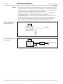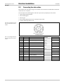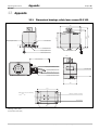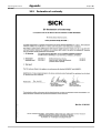
1
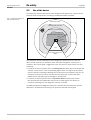
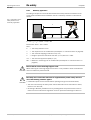
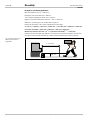
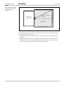
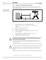
Safety Laser Scanner
RLS 100
&
O
P E R A T I N G
I
N S T R U C T I O N S
Operating Instructions
RLS 100
This document is protected by the law of copyright, whereby all rights established therein remain with the company
SICK AG. Reproduction of this document or parts of this document is only permissible within the limits of the
legal determination of Copyright Law. Alteration or abridgement of the document is not permitted without the
explicit written approval of the company SICK AG.
ESPE 17LL
2
© SICK AG • Industrial Safety Systems • Germany • All rights reserved
8 009 900/06-06-02
Operating Instructions
List of contents
RLS 100
List of contents
1
About this document........................................................................................................................... 5
1.1 The function of this document ................................................................................. 5
1.2 The target group of this document .......................................................................... 5
1.3 Scope ......................................................................................................................... 5
1.4 Depth of information of this document ................................................................... 5
1.5 Abbreviations and terms .......................................................................................... 5
1.5.1 Abbreviations ................................................................................................ 5
1.5.2 Important terms............................................................................................ 6
1.6 Symbols used ............................................................................................................ 6
2
On safety.................................................................................................................................................. 8
2.1 Use of the device....................................................................................................... 9
2.2 Correct use of the device........................................................................................ 10
2.3 General safety information and protective measures .......................................... 10
2.3.1 Stationary application ................................................................................ 11
2.3.2 Application on automated guided vehicles (AGVs) ................................... 14
2.4 Protection of the environment ............................................................................... 17
3
Product description .......................................................................................................................... 18
3.1 Construction of the device...................................................................................... 18
3.2 Operating principles of the device ......................................................................... 21
4
Installation and mounting............................................................................................................... 23
4.1 Operating conditions............................................................................................... 23
4.2 Mounting the device ............................................................................................... 23
4.3 Minimum distance from objects ............................................................................ 25
5
Electrical installation ....................................................................................................................... 26
5.1 Integrating the safety laser scanner RLS 100’s outputs into the machine
control system......................................................................................................... 26
5.2 Connecting the power supply and signal cables ................................................... 28
5.3 Connecting the data cables.................................................................................... 31
6
Configuration ...................................................................................................................................... 33
6.1 Delivery status......................................................................................................... 33
6.2 Preparing the configuration.................................................................................... 33
7
Commissioning................................................................................................................................... 34
7.1 Access authorisation .............................................................................................. 34
7.2 Testing the Monitor functions ................................................................................ 34
7.3 Regular examinations ............................................................................................. 35
8
Transport and storage ..................................................................................................................... 36
8.1 Transporting the safety laser scanner RLS 100 ................................................... 36
8.2 Storage .................................................................................................................... 37
9
Maintenance and care..................................................................................................................... 38
10 Troubleshooting ................................................................................................................................. 39
10.1 Correcting faults...................................................................................................... 39
10.2 LED indications ....................................................................................................... 39
11 Technical data .................................................................................................................................... 40
11.1 Data sheet ............................................................................................................... 40
11.2 Device accuracy and safety supplements ............................................................. 41
8 009 900/06-06-02
© SICK AG • Industrial Safety Systems • Germany • All rights reserved
3
List of contents
Operating Instructions
RLS 100
12 Order data............................................................................................................................................. 42
12.1 Delivery.....................................................................................................................42
12.2 Accessories ..............................................................................................................42
13 Appendix............................................................................................................................................... 43
13.1 Dimensional drawings, safety laser scanner RLS 100..........................................43
13.2 Standards and directives ........................................................................................44
13.3 Declaration of conformity........................................................................................45
13.4 Checklist for the manufacturer...............................................................................46
13.5 List of tables ............................................................................................................47
13.6 List of illustrations ...................................................................................................47
4
© SICK AG • Industrial Safety Systems • Germany • All rights reserved
8 009 900/06-06-02
About this document
Operating Instructions
Chapter 1
RLS 100
1
About this document
Please read this chapter carefully before working with this documentation and the safety
laser scanner RLS 100.
1.1
The function of this document
This document provides information on the technical properties of the Safety Laser
Scanner RLS 100 (Rotating Laser Scanner). You will find information on:
• Safety
• Structure and operation
• Planning
• Maintenance and care
1.2
The target group of this document
This document is intended for those persons who constructively integrate the safety laser
scanner RLS 100, and commission and operate it as a protective device.
1.3
Scope
This document is part of SICK part number 8 009 894 (operating instructions “Safety
Laser Scanner RLS 100” in all available languages). You will find this number on the information label on the system.
1.4
Depth of information of this document
This document contains all the information necessary for planning, acquisition and maintenance of the safety laser scanner RLS 100. Information is provided on its operating principle, possible uses and mounting.
More detailed information is available from SICK AG directly.
ESPE
CDS
1.5
Abbreviations and terms
1.5.1
Abbreviations
Electro-sensitive protective equipment (e.g. safety laser scanner RLS 100)
SICK Configuration & Diagnostic Software. With a PC and the CDS, as a user you can
define the monitored areas, and define or check the correct configuration of the safety
laser scanner RLS 100.
The safety laser scanner RLS 100 uses a reference target fixed to the RLS 100 for selfchecking. Any change to this target is interpreted as a system error.
OSSD
8 009 900/06-06-02
Output signal switching device
© SICK AG • Industrial Safety Systems • Germany • All rights reserved
5
About this document
Chapter 1
Operating Instructions
RLS 100
1.5.2
Important terms
Please distinguish between the following terms:
Machine
In these operating instructions, machine is used as a term for the system to be monitored.
A dangerous state or a dangerous movement that rules out the presence of persons or objects in the protective field, is involved in the operation of the machine.
Scanning range
The maximum scanning range describes an arc of 300° around the sensor with a radius
of max. 7.5 m.
Protective field
The safety area that, when infringed, results in the immediate shut down of the dangerous
movement, is termed the protective field. If a person or object enters the protective field
the safety laser scanner RLS 100 provides a stop signal to the machine via the OSSD
switching outputs.
Protective field size
The maximum protective field size is defined by the distance of the safety laser scanner
scanning head to the most distant point of the protective field including the safety supplement.
Monitored areas
Monitored areas is a general term used for protective fields (up to 6 m) and/or warning
fields (up to 7.5 m). Monitored areas can have irregular shapes or shapes adapted to the
surroundings. The safety laser scanner RLS 100 monitors them continuously by means of
individual radial laser beams.
Warning field
The warning field is described as that safety area whose infringement causes an optical or
acoustic warning signal. If a person or object enters the warning field the safety laser
scanner RLS 100 provides a signal to the monitored machine via the output for warning
field.
1.6
Symbols used
Some information in this document is given particular emphasis to make it easier to find it
quickly.
Recommendation
Note
, Red, + Yellow,
- Green
Take action…
%
Recommendations are designed to give you assistance in your decision-making process
with respect to a function or a technical measure.
Such notes provide information on special device features.
LED symbols describe the state of a diagnostics LED. Examples:
, Red
The red LED is illuminated constantly.
+ Yellow The yellow LED is flashing.
- Green
The green LED is off.
Instructions for taking action are shown by an arrow. Carefully read and follow the instructions for action.
Warning!
A warning indicates an actual or potential risk or health hazard. They are designed to
CAUTION prevent accidents.
Always read warnings attentively and follow instructions carefully!
6
© SICK AG • Industrial Safety Systems • Germany • All rights reserved
8 009 900/06-06-02
About this document
Operating Instructions
Chapter 1
RLS 100
!
Software notes show the location in the CDS (Configuration & Diagnostic Software) where
you can make the appropriate settings and adjustments. In the CDS open the menu View,
Dialog boxes and select the item File Cards to go straight to the above dialog fields. Alternatively, the Software Wizard will guide you through the appropriate setting.
The term “dangerous state”
The dangerous state (standard term) of the machine is always shown in the drawings and
diagrams of this document as a movement of a machine part. In practical operation, there
may be a number of different dangerous states:
• Machine movements
• Electrical conductors
• Visible or invisible radiation
• A combination of several hazards
8 009 900/06-06-02
© SICK AG • Industrial Safety Systems • Germany • All rights reserved
7
On safety
Chapter 2
Operating Instructions
RLS 100
2
On safety
This chapter deals with your safety and the safety of the equipment operators.
%
Safety notes
Please observe the following items in order to ensure the correct and safe use of the
CAUTION safety laser scanner RLS 100.
Prior to commissioning the safety laser scanner RLS 100 for the first time, please read
these operating instructions and the user manual for the CDS (Configuration & Diagnostic
Software) carefully. Get to know the system and the CDS. Please contact the manufacturer
if you have any questions. We would be pleased to provide assistance.
All appropriate legal regulations, the requirements of the trade associations and the instructions of the manufacturer of the machine to be monitored must be observed without
fail.
The protective function of the safety laser scanner RLS 100 depends on the correct definition and programming of the warning field and protective field.
Installation of the safety laser scanner RLS 100, definition and programming of the areas
to be monitored and integration in the machine control system may only be carried out by
authorised personnel who are appropriately trained.
After completing the programming, the arrangement of the protective and warning fields
are to be tested on the machine while it is switched on, but not running. On this topic see
Section 7.2 “Testing the Monitor functions” on page 34.
8
© SICK AG • Industrial Safety Systems • Germany • All rights reserved
8 009 900/06-06-02
Operating Instructions
On safety
Chapter 2
RLS 100
2.1
Use of the device
The safety laser scanner RLS 100 has been developed and approved as a Type 3 electrosensitive protective equipment according to the IEC/EN 61)496-1 standard.
Fig. 1: Schematic diagram of
the monitored areas
Measuring range
Warning field (example)
Maximum protective field
Protective field (example)
6m
7.5 m
60°
Test range (reference
target)
The safety laser scanner RLS 100 has been designed for industrial use. Its task is to
detect access of persons to hazardous areas and stop the dangerous movement of a
machine in this area. A signal is triggered as soon as a person or object enters the monitored area:
• If a person or object is present within the warning field the safety laser scanner RLS 100
switches a relay contact at the corresponding signal output. This signal can be used for
acoustic and optical warnings. Warnings are to indicate that the hazardous area is to be
left before the protective field is activated, and the safety laser scanner RLS 100’s
OSSDs issue a stop signal that would trigger a machine stop.
• If a person or object is present within the protective field the safety laser scanner
RLS 100 switches two independent relay contacts. These signals must lead to an
immediate switching off of the dangerous machine movement.
The CDS (Configuration & Diagnostic Software) is included with the safety laser scanner
RLS 100 for the definition and testing of the protective field and warning field.
8 009 900/06-06-02
© SICK AG • Industrial Safety Systems • Germany • All rights reserved
9
On safety
Chapter 2
Operating Instructions
RLS 100
2.2
Correct use of the device
The safety laser scanner RLS 100 may only be used as protective equipment for detecting
persons or objects (horizontal protective field). Operation of the device is only permissible
according to the technical specifications. All warranty claims against SICK AG are forfeited
in the case of any other use, or alterations being made to devices, even as part of their
mounting or installation.
2.3
%
General safety information and protective measures
The safety laser scanner RLS 100 may only be employed for monitoring tasks fulfilling
all the following conditions:
CAUTION • The safety laser scanner RLS 100 must be able to terminate the dangerous state within
a defined time period by triggering the stop signal.
• The safety distance monitored by the safety laser scanner RLS 100 must be smaller
than the maximum protective field.
• The maximum value of the machine’s stopping time plus the safety laser scanner
RLS 100’s response time must be calculated so that nobody can gain access to the
hazardous point before the dangerous movement has come to a complete stop.
The safety laser scanner RLS 100 is of laser safety class 1.
Additional measures for screening the laser radiation are not
necessary (eye safe).
LASER CLASS 1
10
© SICK AG • Industrial Safety Systems • Germany • All rights reserved
8 009 900/06-06-02
Operating Instructions
On safety
Chapter 2
RLS 100
2.3.1
Stationary application
According to Chapter 6.2 of the EN 999 standard the safety distance between the limit
of the protective field and the hazardous area of a stationary machine is calculated as
follows:
Fig. 2: Calculation of the
safety distance for a
stationary application
S
h
S = 1.6 × (t1 + t2) + (1200 – 0.4 h) + ZM
Please note: 1200 – 0.4 h ≥ 850
Here…
S
= The safety distance in mm
t1
= The response time of the RLS 100 (see Chapter 11 “Technical data” on page 40)
t2
= The machine stopping/run-down time (in ms)
h
= Height of protective field above the floor (in mm) 300 ≤ h < 1000
1.6 = The assumed approach speed (in m/s)
ZM = Maximum measuring error of the RLS 100 (see Chapter 11 “Technical data” on
page 40)
%
Ensure that the correct mounting height is used!
%
The safety laser scanner RLS 100 must be supplemented by further safety devices if
one of the following situations applies:
When selecting the mounting height ensure that it is not possible to enter the hazardous
CAUTION area from below the protective field.
CAUTION • A hazardous point can be reached without passing through the monitored areas;
• The area monitored by the safety laser scanner RLS 100 can be reached from above,
below or from the side;
• According to EN 999, possible access by crawling below the protective field must be
taken into account above the regulation minimum protective field height of 300 mm.
8 009 900/06-06-02
© SICK AG • Industrial Safety Systems • Germany • All rights reserved
11
On safety
Chapter 2
Operating Instructions
RLS 100
Example for a stationary application
Machine width M = 2.2 m = 2200 mm
Response time of the RLS 100 = 280 ms
The machine stopping/run-down time = 300 ms
Height of protective field above the floor = 0.5 m = 500 mm
Maximum measuring error of the RLS 100 = 350 mm
Protective field width = M + safety supplement left and right
S = 1.6 m/s × (280 ms + 300 ms) + (1200 mm – 0.4 × 500 mm) + 350 mm = 2278 mm
Protective field width = 2200 mm + 350 mm + 350 mm = 2900 mm
Maximum protective field size = (S2 + ½ protective field width2)–½ = 2700 mm
Please note: The example only applies if no access from the side is possible. Access from
the side must be prevented either by a wider protective field and/or other measures.
Fig. 3: Example: minimum
distance for stationary
application
S = 2278 mm
500 mm
12
© SICK AG • Industrial Safety Systems • Germany • All rights reserved
8 009 900/06-06-02
Operating Instructions
On safety
Chapter 2
RLS 100
Fig. 4: Maximum protective
field size and safety supplements for stationary
applications
Machine to be
safeguarded
Maximum protective
field size
S
Protective field
Safety supplement front
Safety supplement left
Safety supplement right
Safety supplements are to be determined for maximum protective field sizes.
The following applies if the access of persons from behind cannot be hindered by appropriate sizing of the protective field:
• A manual restart interlock must be present in the machine control system (generally
necessary).
• The width of the accessible, unmonitored area directly in front of the machine must be
smaller than 35 mm for a maximum protective field size of up to 3 m. For larger maximum protective field sizes the distance must be reduced to zero.
8 009 900/06-06-02
© SICK AG • Industrial Safety Systems • Germany • All rights reserved
13
On safety
Chapter 2
Operating Instructions
RLS 100
2.3.2
Application on automated guided vehicles (AGVs)
Taking the regulations for automated guided vehicles (e.g. EN 1525) into account, the
minimum distance between the edge of the protective field and the hazardous area of the
AGV is calculated as follows:
Fig. 5: Calculating the
minimum distance for
automated guided vehicles
S
200 mm > h > 100 mm
S = 1.1 × ((Vmax. × (t1 + t2)) + B) + ZM + F1)
Here…
S
= Minimum distance in mm = max. stopping distance AGV
t1
= Response time of the RLS 100 (see Chapter 11 “Technical data” on
page 40)
t2
= AGV control system reaction time (in ms)
Vmax = Maximum speed of the AGV (m/s)
B
= Maximum braking path for the AGV (in mm)
ZM
= Maximum measuring error of the RLS 100 (see Chapter 11 “Technical
data” on page 40)
F
= Foot clearance: 150 mm (if AGV floor clearance less than 50 mm)
h
= Height of protective field above the floor in mm
1.1
= Safety supplement for possible brake wear
%
The safety laser scanner RLS 100 must be supplemented by further safety devices if
one of the following situations applies:
%
Define protective field cover correctly!
CAUTION • A hazardous point can be reached without passing through the monitored areas;
• The area monitored by the safety laser scanner RLS 100 can be reached from above,
below or from the side.
The protective field must cover the entire width of the AGV. The protective field must be
CAUTION increased at the sides by the safety supplements (see Chapter 11 “Technical data” on
page 40).
1)
14
F only applies when there is no foot clearance according to prEN 1493.
© SICK AG • Industrial Safety Systems • Germany • All rights reserved
8 009 900/06-06-02
On safety
Operating Instructions
Chapter 2
RLS 100
%
CAUTION
%
Define the protective field correctly where routes bisect each other!
At “crossroads” where there are “blind spots”, the protective field must have the same
configuration as in the direction of motion.
Avoid undercutting of the protective field!
The protective field must be configured in such a way that stepping between the protective
CAUTION field and the AGV from behind in the direction of motion (undercutting) is not possible. The
safety laser scanner RLS 100 has a maximum scanning angle of 300°.
Fig. 6: Prevent undercutting
of the AGV protective field
The protective field is to be selected such that it is not possible for a person to pass
unnoticed between the protective field and vehicle.
AGV
If it is not possible to prevent undetected personnel standing in front of the AGV by appropriate sizing of the protective field, then there must be a manual restart interlock in the
AGV.
The width of the accessible area that is not monitored directly in front of the AGV must be
less than 35 mm for a maximum protective field size of up to 3 m. For larger maximum
protective field sizes the distance must be reduced to zero.
%
Program reactivation delay!
In case of AGV applications, you must program a reactivation delay for the safety laser
CAUTION scanner RLS 100. The reactivation delay defines the time [ms] after which the relay is
reactivated when the monitored field is clear (automatic restart after time).
With automatic restart the restart period must be set to a minimum of 2000 ms.
!
8 009 900/06-06-02
You can stipulate the reactivation delay independently for the warning field and the protective field. Device symbol RLS 100, context menu Configuration draft, Edit. The values permitted are between 200 and 5000 ms.
© SICK AG • Industrial Safety Systems • Germany • All rights reserved
15
On safety
Chapter 2
Operating Instructions
RLS 100
Example for application on AGVs
AGVwidth = 1.6 m = 1600 mm
Response time of the RLS 100 = 280 ms
AGV control system reaction time = 300 ms
Maximum speed of the AGV = 1 m/s
Maximum braking distance for the AGV = 0.3 m = 300 mm
Maximum measuring error of the RLS 100 = 250 mm
F unnecessary: the AGV has foot clearance
Safety supplement for possible brake wear = 1.1
Protective field width = AGVwidth + safety supplement left and right
S = 1.1 × ((1 m/s × (280 ms + 300 ms)) + 300 mm) + 250 mm = 1218 mm
Protective field width = 1600 mm + 250 mm + 250 mm = 2100 mm
Maximum protective field size = (S2 + ½ protective field width2)–½ = 1608 mm
Fig. 7: Example: minimum
distance for automated
guided vehicles
S = 1218 mm
200 mm
16
© SICK AG • Industrial Safety Systems • Germany • All rights reserved
8 009 900/06-06-02
Operating Instructions
On safety
Chapter 2
RLS 100
Fig. 8: Maximum protective
field size and safety
supplements for AGVs
Maximum protective
field size
AGV
S
Protective field
Safety supplement front
Safety supplement left
Safety supplement right
2.4
Protection of the environment
The safety laser scanner RLS 100 is constructed in such a way that it adversely affects the
environment as little as possible. It emits and contains no environmentally damaging substances and requires only a minimum of energy and resources.
At work, always act in an environmentally responsible manner. For this reason please note
the following information on disposal.
Disposal
Always dispose of unusable or irreparable devices according to the particular waste disposal regulations applicable in the country of use.
Please note
8 009 900/06-06-02
We would be pleased to be of assistance to you on the disposal of these devices.
Contact us.
© SICK AG • Industrial Safety Systems • Germany • All rights reserved
17
Product description
Chapter 3
Operating Instructions
RLS 100
3
Product description
3.1
Construction of the device
The sensor of the safety laser scanner RLS 100 is housed in a robust aluminium housing.
The housing is protected against water spray according to IP 65 (only applicable if the connection sockets are equipped with plugs or covers).
%
Do not damage seals!
The housing screws are sealed. Any damage to seals leads to forfeiting of the
CAUTION manufacturer’s warranty.
The deflecting mirror and laser optics are located on the top of the housing in a rotating
housing component. The laser transmitter and receiver use the same lens. This complex
co-axial construction prevents angular error resulting from separate transmitter and receiver optics.
Fig. 9: Construction of the
safety laser scanner RLS 100
Rotating scanning
head
LEDs
Electrical
connections
The invisible laser beams emitted conform to laser safety class 1. The measurement area
begins immediately in front of the optics.
%
Do not mount the device at eye level!
Fix the safety laser scanner RLS 100 such that the measuring beam is not at eye level
CAUTION during use.
18
© SICK AG • Industrial Safety Systems • Germany • All rights reserved
8 009 900/06-06-02
Operating Instructions
Product description
Chapter 3
RLS 100
There are four LEDs on the side of the housing showing the state of the system:
Fig. 10: LEDs on the safety
laser scanner RLS 100
Reference target
Rotating scanning head
Green
Outputs for protective field (OSSDs) in ON state
Red
Outputs for protective field (OSSDs) in OFF state
Yellow
Outputs for warning field in OFF state
Yellow
System state
&
Tab. 1: Status of the LEDs for
the safety laser scanner
RLS 100
LED indication
Green
Red
Yellow
Yellow
-
-
-
-
Device switched off
,
,
,
,
Test LEDs for 1 sec. after Power On2)
,
-
-
-
The system is ready for operation, the outputs for
protective field (OSSDs) and for warning field are in
an ON state
-
,
-
Outputs for protective field (OSSDs) in OFF state
,
-
Outputs for warning field in OFF state
,
+)3)
-
2)
3)
8 009 900/06-06-02
Meaning
,
System error
The system state LED lights up during the start-up test after Power On. During the last 5 seconds before
operational readiness is achieved and the release of the outputs for protective field (OSSDs) this LED blinks at
2 Hz.
On this topic see Section 10.2 “LED indications” on page 39.
© SICK AG • Industrial Safety Systems • Germany • All rights reserved
19
Chapter 3
Product description
Operating Instructions
RLS 100
There are two connection sockets on the opposite side of the housing labelled Interface
and 24 V DC/signal. The appropriate plugs are supplied with the safety laser scanner.
Fig. 11: Housing
connection side
Rotating scanning head
Reference target
Connection signals and
24 V-power supply
Interface connection
Protective cap
for interface
Fuse 3.15 A medium slow
blow under cover with
sealing ring
Earth connection
• Interface
Communication with the computer or restart. At this connection an RS 232 interface is
available.
• 24 V DC/signal
For connecting the power supply, the two outputs for protective field, OSSD1 and
OSSD2, and the output for warning field.
20
© SICK AG • Industrial Safety Systems • Germany • All rights reserved
8 009 900/06-06-02
Operating Instructions
Product description
Chapter 3
RLS 100
3.2
Operating principles of the device
Measurement principle
The safety laser scanner RLS 100 emits pulsed laser beams throughout a complete 360°
with the help of a rotating mirror. The light pulses are reflected diffusely from objects in the
vicinity and received by a photodiode in the sensor. The safety laser scanner RLS 100
derives the distance to the object from the propagation time that the light requires from
emission to reception of the reflection at the sensor.
Fig. 12: Schematic diagram
of safety laser scanner
RLS 100 operating principle
Rotating deflecting
mirror
Laser reflection
Laser beam
Laser optics
Stopwatch
stops
starts
Laser receiver
Laser sender
triggers
Sampling
D=
∆ T × VLight
2
Angular encoder
Motor
The direction of each individual measurement beam is determined with the help of an
angular encoder.
The measurement data for distance and direction can be called up by a computer via the
interface.
8 009 900/06-06-02
© SICK AG • Industrial Safety Systems • Germany • All rights reserved
21
Product description
Chapter 3
Operating Instructions
RLS 100
Monitoring of protective field and warning field
Two distance limit values, representing the warning field and protective field, can be defined for each measurement beam with the help of the CDS. During monitoring the safety
laser scanner RLS 100 compares the measured object distance with defined limit values.
Fig. 13: Configuration of
monitored areas
Warning field
Warning field
Protective field
RLS
RLS
Protective field
60°
Possible configuration
Impossible configuration
The tables of distance limit values are determined with a computer and laid down in the
safety laser scanner RLS 100. The warning and protective field limits can be of any shape
and ideally adapted to the surroundings. The safety laser scanner RLS 100 must therefore
be within the limits of both the warning field and the protective field.
Self-testing
Comprehensive internal tests run continuously within the safety laser scanner RLS 100.
This ensures the system’s high level of operational reliability. All basic components are
either present in duplicate or are monitored by testing logics that operate independently.
The so-called reference or test target is an important constituent of the self-testing
systems. This involves a stationary target firmly mounted on the safety laser scanner
RLS 100, detected on each rotation. Any alteration in the measurement value indicates a
system error and leads to an error state.
While monitoring, the safety laser scanner RLS 100 checks that it is functioning correctly.
The system sensitivity of the device is monitored through the measurement of the light reflected from the reference target. Contamination of the optics or the reference target can
thus lead to the system analysis: Device insensitive/reference target error (LED indicators). In such a case, clean the device optics as well as the reference target as per the instructions given in Section 9 “Maintenance and care” on page 38.
22
© SICK AG • Industrial Safety Systems • Germany • All rights reserved
8 009 900/06-06-02
Operating Instructions
Installation and mounting
Chapter 4
RLS 100
4
Installation and mounting
4.1
Operating conditions
Please note the following points before using the device:
• The device is only for use in predominantly enclosed areas.
• The safety laser scanner RLS 100 is protected against water spray according to IP 65
and operates within a temperature range of 0 to 50 °C. Protect the system from moisture and temperatures that are outside the temperature range.
• Protect the safety laser scanner RLS 100 from continuous direct sunlight.
• To prevent condensation do not expose the safety laser scanner RLS 100 to rapidly
changing temperatures.
• Do not expose the safety laser scanner RLS 100 to aggressive chemicals (detergents).
• Glass panes or reflective surfaces are not reliably detected by the safety laser scanner
RLS 100 as objects.
• The safety laser scanner RLS 100 only detects objects that are visible from its location
and not covered up.
• Rain, snow, dust and smoke are detected as “objects” and may trigger warning field or
protective field states.
4.2
%
Mounting the device
Observe the machine manufacturer’s safety regulations!
It is essential that the safety instructions for working on the machine, defined by the
CAUTION machine manufacturer, are observed when mounting the safety laser scanner RLS 100.
Mounting of the safety laser scanner RLS 100 may only be carried out by qualified
personnel.
The safety laser scanner RLS 100 can be mounted in any orientation (standing, hanging,
lying).
8 009 900/06-06-02
© SICK AG • Industrial Safety Systems • Germany • All rights reserved
23
Installation and mounting
Chapter 4
Operating Instructions
RLS 100
Note
Fig. 14: Minimum distance to
the floor
The emitted laser beam has a divergence of 1°. This means that it is essential that during
mounting a minimum distance of 100 mm to the floor must be maintained.
Measuring range
Minimum distance to the floor
Note
When installing several safety laser scanners, mounting must be carried out in such a way
that there cannot be any mutual interference:
Fig. 15: Mounting several
safety laser scanners
h
Invalid configuration
min. 500 mm
Possible configuration
Possible configuration
Screening
Possible configuration
You require the following aids for mounting the device:
• 4 bolts M)4)×)10 for fastening to a horizontal surface
• 4 washers and locking washers
• If necessary, a spirit level for ensuring level mounting
24
© SICK AG • Industrial Safety Systems • Germany • All rights reserved
8 009 900/06-06-02
Operating Instructions
Installation and mounting
Chapter 4
RLS 100
Fit safety laser scanner RLS 100 to machine:
1. Switch off the machine and check that you are not taking any risks!
2. Turn the mounting screws with the washers and locking washers in place and tighten
them up finger tight.
3. When attaching to non-mobile machines it is recommended that the spirit level is used
in two axes to ensure level mounting.
4. Tighten the attachment screws.
4.3
Minimum distance from objects
When mounting in front of a wall, for reasons of availability the programmed monitored
areas may not be closer than 25 cm to the wall.
Fig. 16: Minimum distance of
the area monitored by the
safety laser scanner RLS 100
from surrounding objects
Wall
Minimum distance
Monitored areas
RLS
Machine to be
safeguarded
8 009 900/06-06-02
© SICK AG • Industrial Safety Systems • Germany • All rights reserved
25
Electrical installation
Chapter 5
Operating Instructions
RLS 100
5
Electrical installation
5.1
%
Integrating the safety laser scanner RLS 100’s outputs
into the machine control system
Connection only by qualified personnel!
Connection of the safety laser scanner RLS 100 to the machine may only be carried out by
CAUTION appropriately qualified personnel.
These persons must have all the information provided by the suppliers of the machine.
Fig. 17: Example of
integration of the
warning field signal
30 V max.
L
Warning field1
Warning field2
0V
N
Three potential-free switching outputs are available for connection to the machine for
warning field and protective field states. The outputs are designed as N.)O. contacts.
Switching output for warning field
The switching output for warning field can be used for the output of a warning signal. The
switching output for warning field is opened when the warning field is activated or there is
a safety laser scanner RLS 100 fault.
If an object is again removed from the warning field, its switching output closes after an
adjustable time from 200 to 5000 ms (reactivation delay).
The switching output for warning field can be switched with a maximum of 30 Volts and is
internally fuse-protected with 2 Amps.
26
© SICK AG • Industrial Safety Systems • Germany • All rights reserved
8 009 900/06-06-02
Electrical installation
Operating Instructions
Chapter 5
RLS 100
Fig. 18: Example of integration of the OSSD switching
outputs. The wiring is to be
laid down in such a way that
it is protected against
mechanical effects.
* = screen to rule out crosscircuits
24 V
Monitoring of K1
and K2
OSSD2.1
K1
OSSD2.2
K1
OSSD1.1
*
K2
*
K2
Safe controller as a
minimum category 3
in accordance with
DIN EN 954-1
OSSD1.2
Suppression diode
K1
K2
Suppression diode
Relay with positively-driven contacts
0V
OSSD switching outputs
The OSSD switching outputs can be used as emergency stop trips in the system controller.
The OSSD switching outputs are open if
• the protective field has been activated
or
• the safety laser scanner RLS 100 has a fault.
The switching output closes after a programmable time of between 200 and 5000 ms (reactivation delay), assuming that there is no system fault.
!
You can stipulate the reactivation delay independently for the warning field and the protective field. Device symbol RLS 100, context menu Configuration draft, Edit.
The OSSD1 and OSSD2 outputs can be wired with a maximum of 30 Volts and are internally fuse-protected with 2 Amps.
8 009 900/06-06-02
© SICK AG • Industrial Safety Systems • Germany • All rights reserved
27
Electrical installation
Chapter 5
Operating Instructions
RLS 100
5.2
%
Connecting the power supply and signal cables
Electrical work is only to be carried out by appropriately trained electrical specialists!
CAUTION Electrical connection of the power supply and connection of the signal cables for the warning field, OSSD1 and OSSD2 take place together via the middle socket on the right-hand
side of the housing. The correct connection plug is supplied with the RLS. You will need the
following tools for electrical connection:
• 1 open-ended spanner AF16
• 1 fine soldering iron
• 1 hot-air gun
• shrink-tubing appropriate for the connection wires used
Fig. 19: Plug allocation for
connection of the power
supply and the signal cables
View on the solder side of
the 8-pin socket
Tab. 2: Plug allocation for
connection of the power
supply and the signal cables
28
Pin
Signal
Explanation
Colour
Marking
1
24 V
24 V DC supply
Brown
+
2
GND24
Ground
Blue
–
3
OSSD2.1
Relay contact for protective field 2.1
White
S2
4
OSSD2.2
Relay contact for protective field 2.2
Grey
S2
5
OSSD1.1
Relay contact for protective field 1.1
Black
S1
6
OSSD1.2
Relay contact for protective field 1.2
Green
S1
7
Warning field1.1
Relay contact for warning field 1.1
Red
A
8
Warning field1.2
Relay contact for warning field 1.2
Pink
A
FE
Functional earth (shield)
Black
FE
© SICK AG • Industrial Safety Systems • Germany • All rights reserved
8 009 900/06-06-02
Electrical installation
Operating Instructions
Chapter 5
RLS 100
Connecting the power supply to the safety laser scanner RLS 100:
1. Wiring is to be protected.
2. Turn off the machine and make sure that you are not exposed to any danger.
3. Avoid short-circuits.
4. Prepare the connection cable:
– number of wires: 8
–
outside diameter: 5 … 8 mm
–
wire cross-section: 0.50 … 0.75 mm2
–
maximum cable length (0.5 mm² cross-section of wire): 20 m
–
use screened cable
5. Cable cross-section for functional earthing/ground 1 … 2 mm2
6. Prepare the power supply:
– operating voltage for the safety laser scanner RLS 100: 24 V DC ± 25)%
–
power consumption in operation: typically 750 mA at 24 V DC (switch on current: 2 A
for 100 ms)
7. Open and prepare the 8-pin Binder type cable plug supplied:
– feed the cable through the crocodile clip and spring collar
–
screw the clip for cable strain relief tight
8. Push an approx. 2 cm long piece of shrink-tubing onto each wire.
9. Solder the signal and power supply wires to the plug as shown in Fig. 18.
10. Push the shrink-tubing over the soldered contacts and shrink it with hot air.
Note
Soldering, and insulation of the individual contacts with the shrink-tubing, must be
carried out with great care to prevent the risk of short-circuits.
11. Attach the plug as described in the manufacturer’s mounting instructions:
– screw sheath onto socket insert
–
push crocodile clip up to sheath and tighten screw
–
push threaded ring onto the sheath until the springs snap in
12. Connect the plug to the safety laser scanner RLS 100’s 24 V DC/signal socket and
tighten the screw.
13. Connect safety laser scanner RLS 100 and computer.
14. Switch on safety laser scanner RLS 100.
15. The prismatic head starts to rotate. After a few seconds the system state LED goes out
and the safety laser scanner RLS 100 is ready for configuration of the areas to be monitored.
8 009 900/06-06-02
© SICK AG • Industrial Safety Systems • Germany • All rights reserved
29
Electrical installation
Chapter 5
Operating Instructions
RLS 100
Notes
• On connecting the safety laser scanner RLS 100 it is imperative to ensure that the earth
is connected correctly. The safety laser scanner RLS 100 must be provided with a safety
insulating transformer according to IEC 742. This also applies for the charging devices
for vehicle batteries, if charging is to take place on the vehicle.
• For stationary applications, the safety laser scanner RLS 100 must be earthed (earth
connection see Section 3.1 “Construction of the device” on page 18).
• The functional earth is to be connected with ground potential for installation on transport vehicles. For applications with battery-powered vehicles a DC voltage transformer
must be connected in series before the safety laser scanner RLS 100. On request,
please consider a relevant protection against “low dump” (voltage drop).
Fig. 20: Example of the power
supply and grounding of
stationary applications
24 V DC
0 V DC
FE
Fig. 21: Example of the power
supply and grounding on a
transport vehicle
24 V DC
On-board voltage
GND
30
© SICK AG • Industrial Safety Systems • Germany • All rights reserved
8 009 900/06-06-02
Operating Instructions
Electrical installation
Chapter 5
RLS 100
5.3
Connecting the data cables
Data cables with 9-pin D-sub plugs are available as accessories from SICK AG as standard
connection to a computer.
You will require the following parts and tools if you have to prepare your own cable:
• 1 open-ended spanner AF16
• 1 fine soldering iron
• 1 hot-air gun
• shrink-tubing appropriate for the connection wires used
• 1 14-pin cable plug, Binder type
Fig. 22: Pin assignments for
the connection of the data
cables
View on the solder side of
the 14-pin socket
Tab. 3: Pin assignments for
the connection of the data
cables
8 009 900/06-06-02
Pin
Signal
Explanation
Direction
Level
A
GND
Ground, RS 232
---
---
C
RTS
RS 232: Ready to send
Output
24 V
E
CTS
RS 232: Clear to send
Input
24 V
G
TxD
RS 232: Transmit data
Output
24 V
J
RxD
RS 232: Receive data
Input
24 V
L
---
Do not connect!
---
---
M
RES
Reset (active LOW)
Input
24 V
N
---
Do not connect!
---
---
O
---
Do not connect!
---
---
P
---
Do not connect!
---
---
R
---
Do not connect!
---
---
S
---
Do not connect!
---
---
T
---
Do not connect!
---
---
U
---
Do not connect!
---
---
© SICK AG • Industrial Safety Systems • Germany • All rights reserved
31
Chapter 5
Electrical installation
Operating Instructions
RLS 100
Connecting the data cables of the computer to the safety laser scanner RLS 100:
1. Prevent short-circuits and switch off the safety laser scanner RLS 100 and the
computer.
2. Prepare the data cable:
– number of wires for RS 232 : 5
–
outside diameter: 5 … 8 mm
–
wire cross-section: 0.14 … 0.75 mm2
–
maximum length of wire: 15 m
–
use screened cable if there are strong interfering fields!
3. Open and prepare the 14-pin Binder type cable plug:
– feed the cable through the crocodile clip and spring collar
–
screw the clip for cable strain relief tight
4. Push an approx. 2 cm long piece of shrink-tubing onto each wire.
5. Solder the data cables of the RS 232 link in the plug as shown in the wiring diagram.
6. Push the shrink-tubing over the soldered contacts and shrink it with hot air.
7. Attach the plug:
– screw sheath onto socket insert
–
push crocodile clip up to sheath and tighten screw
–
push threaded ring onto the sheath until the springs snap in
8. Connect plug to safety laser scanner RLS 100’s interface socket and screw tight.
9. The device only conforms to enclosure rating IP 65 if the interface socket is provided
with a plug, or covered using a cap.
32
© SICK AG • Industrial Safety Systems • Germany • All rights reserved
8 009 900/06-06-02
Operating Instructions
Configuration
Chapter 6
RLS 100
6
Configuration
6.1
Delivery status
No protective field or warning field is defined in the safety laser scanner RLS 100 as supplied. The relay reactivation delay is set to the standard value of 200 ms. Prior to
commissioning, the safety laser scanner RLS 100 must be configured for the planned
application with the aid of the CDS (Configuration & Diagnostic Software) supplied.
6.2
Preparing the configuration
How to prepare the configuration:
Make sure that the safety laser scanner RLS 100 has been properly mounted and that
the electrical connections are correct and in place.
Plan all settings necessary (warning field, protective field, reactivation delay, etc.).
To configure the safety laser scanner RLS 100, you need:
–
CDS (Configuration & Diagnostic Software) on CD-ROM
–
User manual for CDS on CD-ROM
–
PC/Notebook with Windows 9x/NT 4/2000 Professional/XP and a serial interface
(RS 232). (PC/notebook not included)
–
Connecting cable for the connection between PC and safety laser scanner RLS 100
(connecting cable not included)
To configure the device, please read the user manual for the CDS (Configuration &
Diagnostic Software) and use the online help in the programme.
8 009 900/06-06-02
© SICK AG • Industrial Safety Systems • Germany • All rights reserved
33
Commissioning
Chapter 7
Operating Instructions
RLS 100
7
Commissioning
7.1
Access authorisation
Access to the safety laser scanner RLS 100 is password protected.
• The password is RLS1 on delivery.
• The user (Safety Officer) must ensure that the password is only known by authorised
persons.
Recommendation
!
It is recommended that the RLS1 password is replaced by a new password that you
select.
Device symbol RLS 100, context menu Access rights, Change password…
• It is possible to select the Monitor function on the PC and edit protective fields without a
password, but it is not possible to change the protective field or parameters without it.
• Using password it is possible to change the protective field and parameters.
7.2
Testing the Monitor functions
After you have defined the monitored areas with the CDS you must check and accept the
installation. For this purpose proceed in two steps:
• First check the definition of the protective field with a computer connected and document the test.
• Then connect the machine and repeat the test.
Check definition of the protective field and document:
Insert a dark test object with a diameter of about 70 mm from all sides into the protective field. Check every section of the protective field limit.
The green LED must go out and the red LED on the front of the safety laser scanner
RLS 100 must light up.
Checking installation of the safety system to the machine:
When you are sure that the definition of the protective field is correct, connect the safety
laser scanner RLS 100 signal cables to the machine control system. Repeat the test with
the machine switched on but not running. Check as far as possible the behaviour of the
protective device.
Also check the behaviour when the safety laser scanner RLS 100 is switched off.
Switch on the machine. Carefully insert an object, e.g. a box, into the monitored areas.
Observe the machine’s reaction.
Prepare a report.
34
© SICK AG • Industrial Safety Systems • Germany • All rights reserved
8 009 900/06-06-02
Operating Instructions
Commissioning
Chapter 7
RLS 100
Before accepting the system take the following points into consideration:
Use the test to ensure that no dangerous state can be set in motion as long as an object
is present in the hazardous area.
Ensure that the dangerous state or the dangerous movement comes to a stop before
any part of a person’s body can reach the hazardous point. When defining the protective
field, take the machine stopping/run-down time and the safety laser scanner RLS 100’s
response time into account.
Ensure that the safety laser scanner RLS 100 and other protective devices monitor all
access points to the hazardous areas.
Check that the safety laser scanner RLS 100 is firmly mounted. Check that the system
doesn’t move under normal operating conditions and that its position cannot be
changed.
Train the machine operating personnel in how the safety laser scanner RLS 100 operates. Explain its design and how to use the system (LEDs, faults).
7.3
%
Regular examinations
Carry out regular tests!
Daily tests can be carried out by the machine’s operating personnel.
CAUTION The six-monthly maintenance (see below) and testing of the monitored areas may only be
carried out by authorised Safety Officers.)
Daily tests
Check the state and installation of the safety laser scanner RLS 100 for any changes. If
in doubt switch off the safety laser scanner RLS 100 and immediately inform the Safety
Officer.
Keep the optics clean. Only use a soft brush or optical cloth for cleaning the optics.
Check the surroundings for changes (e.g. structural alterations) that may have taken
place since configuration.
Six-monthly tests
Check the definition of the protective field at least every six months.
Follow the regulation procedure described in Section 7.2 “Testing the Monitor functions”
on page 34.
8 009 900/06-06-02
© SICK AG • Industrial Safety Systems • Germany • All rights reserved
35
Transport and storage
Chapter 8
Operating Instructions
RLS 100
8
Transport and storage
8.1
Transporting the safety laser scanner RLS 100
Adhere to the following instructions when transporting the safety laser scanner RLS 100:
Notes
1. Remove all plugs to prevent buckling of the cable.
2. Fix rotating parts with adhesive tape to prevent scratching of the optics.
3. Do not allow any mechanical loads to affect the rotating parts.
4. Use the original packaging.
This is how you pack the safety laser scanner in its original packaging:
1. Place the lower membrane cushion upright in the box and lay the safety laser scanner
RLS 100 on it on its side.
Fig. 23: Place RLS 100 on its
side in the original packaging
2. Place the upper membrane cushion on top of the safety laser scanner RLS 100.
Fig. 24: Place the upper
membrane cushion on top of
the RLS 100
36
© SICK AG • Industrial Safety Systems • Germany • All rights reserved
8 009 900/06-06-02
Transport and storage
Operating Instructions
Chapter 8
RLS 100
3. Finally, place the accessories in the box.
Fig. 25: Put the accessories
in the original packaging
4. Before sending the package label it clearly: “Sensitive measurement device – fragile!”
8.2
Storage
Adhere to the following instructions when storing the safety laser scanner RLS 100:
Notes
Carefully dry the system before storage. Condensation can damage optical parts.
Do not store the system in closed airtight containers, so that any remaining dampness
can evaporate. If possible, use the original packaging.
Store with an air humidity of 5 to 85)% (without condensation)
Storage temperature –20 to +70 °C
8 009 900/06-06-02
© SICK AG • Industrial Safety Systems • Germany • All rights reserved
37
Maintenance and care
Chapter 9
Operating Instructions
RLS 100
9
Maintenance and care
The safety laser scanner RLS 100 requires no maintenance apart from the regular examinations already mentioned. No adjustments or calibration are necessary.
Please observe the following general instructions for handling the safety laser scanner
RLS 100:
Notes
You should clean the beam exit (prism) of the scanning head as soon as there is evidence of visible contamination, so that the sensor operates without error. Do not touch
the prism directly when cleaning. Use a plastic cleaner with a soft optical cloth to clean
the prism. Never use rough cloths or aggressive detergents such as acetone.
Clean the safety laser scanner RLS 100’s housing with a soft, damp cloth. Do not use
aggressive detergents.
Protect the safety laser scanner RLS 100 from continuous direct sunlight.
Do not expose the safety laser scanner RLS 100 to rapid temperature changes to prevent the formation of condensation.
Never open the safety laser scanner RLS 100! The system does not contain any components that can be repaired or maintained by the operator.
If errors occur or you have difficulty using the safety laser scanner RLS 100, SICK’s
Customer Service would be pleased to be of assistance.
Moreover, SICK offers Installation and Commissioning Service packages. Our Customer
Service will provide further assistance if required.
38
© SICK AG • Industrial Safety Systems • Germany • All rights reserved
8 009 900/06-06-02
Troubleshooting
Operating Instructions
Chapter 10
RLS 100
10
Troubleshooting
10.1
Correcting faults
All the LEDs are off and the laser optics are not rotating:
• Power supply 18 … 30 V (24 V ± 25)%) present?
• Fuse intact?
• Plug correctly mounted on the safety laser scanner RLS 100 and tightly connected?
• Plug cables with correct polarity?
Green LED for “System OK” does not light up, OSSDs and warning field are active
• Clean optics (see Section 7.3 “Regular examinations” on page 35).
• Check power supply for high current.
• Connect the computer and display the CDS diagnostics.
!
Device symbol RLS 100, context menu Diagnostics, Display.
• If you cannot solve the problem, please send the safety laser scanner RLS 100 to SICK’s
Customer Service.
Objects within the monitored areas are not detected:
• Is the yellow LED for system state lit or blinking?
!
–
Yes: the safety laser scanner RLS 100 has found an error: Check optics.
–
No: With the aid of the computer and the CDS, check the definitions for the protective
and warning field.
Device symbol RLS 100, context menu Configuration draft, Edit monitored areas.
Objects are reported within the monitored areas without actually existing:
• Check the surroundings for changes (e.g. structural alterations) that may have taken
place since configuration.
• Rain, snow, smoke and dust could be the cause of the spurious object detection!
10.2
Fig. 26: The system state LED
indications
LED indications
System state LEDs
Meaning
System state error-free
Error at reference target
Rotational frequency error
Comparison error
Relay error
Error, self-test
0.5 s
0.5 s
Repetition 8 s
ON
8 009 900/06-06-02
Repetition 8 s
OFF
© SICK AG • Industrial Safety Systems • Germany • All rights reserved
39
Technical data
Chapter 11
Operating Instructions
RLS 100
11
Technical data
11.1
Tab. 4: Technical data for
the safety laser scanner
RLS 100
Data sheet
Safety classes
Safety category
Type 3 ESPE acc. to EN 61)496-1
error-proof acc. to EN 61)496-1
Laser protection class
IEC 825 Laser Class 1
Characteristic data for the safety laser scanner RLS 100
Measurement and tolerance
range
0 to 7.5 m
Range for a safe detection of
the “nominal leg”4)
0 to 6 m (incl. safety supplement)
Protective field response time
280 ms
Maximum angle
300°
Laser and angular measurement
Laser diode
Avalanche Photo Diode
Wavelength
905 nm
Laser protection class
1 (IEC 825)
Pulse frequency
5.76 KHz + 5)%
Scanning frequency
8 Hz + 5)%
Scanning angle
300°
Angle encoder resolution
360)×)4 increments
Point resolution
0.5°
Optics (co-axial transmitter and receiver optics)
Laser beam divergence
15 mrad
Focal length
30 mm
Lens diameter
30 mm
Power supply
Operating voltage
24 V DC ± 25)% (via a safety insulating transformer acc.
to IEC 742, see section 5.2 “Connecting the power
supply and signal cables” on page 28).
Current uptake
Approx. 1 A at 24 V DC
Switch on current
2 A for 100 ms
Power consumption
24 W total
4)
40
Definition of the “nominal leg”: black cylinder with 70 mm diameter and 1.8)% reflectivity. This corresponds
approximately to a leg in child’s clothing made of black corduroy.
© SICK AG • Industrial Safety Systems • Germany • All rights reserved
8 009 900/06-06-02
Operating Instructions
Technical data
Chapter 11
RLS 100
Tab. 4: Technical data for the
safety laser scanner RLS 100
(contd.)
Housing and environmental resistance
Material
Aluminium
Enclosure rating
IP 65
Length
168 mm
Width
108 mm
Height
176 mm
Weight
Ca. 3.0 kg
Operating temperature
0 … 50 °C
Storage temperature
–20 … 70 °C
Interfaces
Data interfaces to computer
RS 232: 9600 baud, 8 data bits, 1 stop bit, no parity
Signal outputs for warning field, Potential-free relay outputs, max. 2 A, max. 30 V, purely
OSSD1, OSSD2
Ohmic load, number of operations 2 million
Cable plug
Interface connection
14-pin, Binder type
24 V DC/signal connection
8-pin, Binder type
11.2
Device accuracy and safety supplements
The accuracy of the device depends on distance. Accuracy is as follows:
Tab. 5: Accuracy of the
RLS 100 in relation to
distance
Distance up to
Safety supplement
2 metres
5)
25 cm
3 metres
5)
35 cm
4 metres5)
45 cm
5 metres
5)
55 cm
6 metres
5)
70 cm
All possible influences, and particularly the reflective properties of the materials that could
come into question and all background effects, have been taken into consideration in
these tolerances.
Please note that when programming the device the safety supplement must be calculated
in.
5)
8 009 900/06-06-02
All distance figures include safety supplement.
© SICK AG • Industrial Safety Systems • Germany • All rights reserved
41
Order data
Chapter 12
Operating Instructions
RLS 100
12
Order data
12.1
Delivery
The precise order description for the RLS 100 is:
Safety laser scanner RLS 100, part number 6 022 627
The following components are supplied as constituents of the safety laser scanner
RLS 100 package:
• Safety laser scanner RLS 100
• Technical documentation with configuration software
• Bolt set 1 (fastening to the underside of the safety laser scanner RLS 100):
–
4 bolts M)4)×)10
–
4 washers
–
4 locking washers
• Cable for power supply and switching signals
• Plastic cap for the interface socket
• Packing instructions
• Packaging box
12.2
Accessories
Independent of the number of safety laser scanners that you want to use you will need at
least one
• RS 232 cable for the connection to the computer (part number: 6 024 723)
42
© SICK AG • Industrial Safety Systems • Germany • All rights reserved
8 009 900/06-06-02
Operating Instructions
Appendix
Chapter 13
RLS 100
13
Appendix
13.1
Dimensional drawings, safety laser scanner RLS 100
176
Fuse 3.15 A M
19
178±1
15.5
15
137.5±1
Flange plug 14P interface
±1
158
&
Across flats 4 mm
11
Flange plug 8P 24 V DC
Mounting area
10
Interface protective cap
56.5
Min. 175 distance
Approx. 60
Coupling socket PG9 8-pin socket
&
Information label
Bending radius 90 mm min.
Bending radius 112 mm min.
Coupling socket 14-pin socket
LEDs
green red yellow yellow
115
176
Holes diagram, four-point fastening
4 × 4.5+0.2 mm
115
86±0.2
Fastening thread M 4 × 10 deep
Mounting area
144±0.2
Fig. 27: Dimensional
drawings, safety laser
scanner RLS 100 (mm)
8 009 900/06-06-02
© SICK AG • Industrial Safety Systems • Germany • All rights reserved
43
Chapter 13
Appendix
Operating Instructions
RLS 100
13.2
Standards and directives
The most important standards and directives, valid for the use of opto-electronic protective
devices in Europe, are listed below. Further regulations may be of importance to you,
depending on the type of use. Information on further device-specific standards can be
obtained from the responsible authorities or from your trade association.
If the machine or vehicle is to be operated in a country that does not belong to the
European Union, we recommend that you contact the plant operator or local authorities.
On the application and installation of protective equipment
• The Machinery Directive 98/37/EC
• Safety of machinery – Basic concepts, general principles for design (EN 292)
• The safety of integrated production systems (DIN EN 1921)
• Safety of machinery – Electrical machine equipment – Part 1: General requirements
(EN 60)204)
• Safety of machinery – Safety distances to prevent danger zones being reached by the
upper limbs (EN 294)
• Safety requirements for robots (EN 775)
• Safety rules for electro-sensitive protective equipment on power-driven equipment
(ZH 1/597)
• Safety of machinery – The positioning of protective equipment in respect of approach
speeds of parts of the human body (EN 999)
• Safety of machinery – Principles for risk assessment (EN 1050)
On the construction and equipping of protective equipment
• Safety of machinery – Electro-sensitive protective equipment – Part 1: General
requirements (IEC/EN 61)496-1 as well as based on IEC/EN 61)496-3)
• Basic safety considerations for MCR safety systems (DIN V 19)250)
• Safety of machinery – Electrical equipment of machines – Part 1: General requirements
(EN 60)204)
• Safety of machinery – Safety-related parts of control systems – General principles for
design (EN 954)
Please request our brochure on this topic “Safe machinery with opto-electronic protection”.
44
© SICK AG • Industrial Safety Systems • Germany • All rights reserved
8 009 900/06-06-02
Operating Instructions
Appendix
Chapter 13
RLS 100
13.3
8 009 900/06-06-02
Declaration of conformity
© SICK AG • Industrial Safety Systems • Germany • All rights reserved
45
Chapter 13
Appendix
Operating Instructions
RLS 100
13.4
Checklist for the manufacturer
&
Check list for the manufacturer/OEM for the installation of
electro-sensitive protective equipment (ESPE).
The details on the items listed below must be available at the latest when the system is commissioned for the first
time, depending, however, on the various applications the requirements of which must be reviewed by the manufacturer/OEM.
This checklist should be retained and kept with the machine documentation to serve as reference during recurring
tests.
1. Have the safety rules and regulations been observed in compliance with the directives/standards applicable to the machine?
Yes
No
2. Are the applied directives and standards listed in the declaration of conformity?
Yes
No
3. Does the protective device comply with the required control category?
Yes
No
4. Is the access to the hazardous area/ hazardous point only possible through the protective field
of the ESPE?
Yes
No
5. Have appropriate measures been taken to prevent (mechanical point-of-operation guarding) or
monitor unprotected presence in the hazardous area when protecting a hazardous
area/hazardous point and have these been secured against removal?
Yes
No
6. Are additional mechanical protective measures fitted and secured against manipulation which
prevent reaching below, above or around the ESPE?
Yes
No
7. Has the maximum shutdown and/or stopping/run-down time of the machine been measured,
specified and documented (at the machine and/or in the machine documentation)?
Yes
No
8. Has the ESPE been mounted such that the required safety distance from the nearest hazardous
point has been achieved?
Yes
No
9. Are the ESPE devices properly mounted and secured against manipulation after adjustment?
Yes
No
10. Are the required protective measures against electric shock in effect (protection class)?
Yes
No
11. Is the command unit for resetting the protective equipment (ESPE) or restarting the machine
present and correctly installed?
Yes
No
12. Are the outputs of the ESPE (OSSDs) integrated in compliance with the required control category
and does the integration comply with the circuit diagrams?
Yes
No
13. Has the protective function been checked in compliance with the test notes of this
documentation?
Yes
No
14. Are the given protective functions effective at every setting of the operating mode selector
switch?
Yes
No
15. Are the switching elements activated by the ESPE, e.g. contactors, valves, monitored?
Yes
No
16. Is the ESPE effective over the entire period of the dangerous state?
Yes
No
17. Once initiated, will a dangerous state be stopped when switching the ESPE on or off and when
changing the operating mode, or when switching to another protective device?
Yes
No
This checklist does not replace the initial commissioning, nor the regular inspection by specialist personnel.
46
© SICK AG • Industrial Safety Systems • Germany • All rights reserved
8 009 900/06-06-02
Operating Instructions
Appendix
Chapter 13
RLS 100
8 009 900/06-06-02
13.5
List of tables
Tab. 1:
Status of the LEDs for the safety laser scanner RLS 100 .................................... 19
Tab. 2:
Plug allocation for connection of the power supply and the signal cables.......... 28
Tab. 3:
Pin assignments for the connection of the data cables ....................................... 31
Tab. 4:
Technical data for the safety laser scanner RLS 100........................................... 40
Tab. 5:
Accuracy of the RLS 100 in relation to distance................................................... 41
13.6
List of illustrations
Fig. 1:
Schematic diagram of the monitored areas............................................................ 9
Fig. 2:
Calculation of the safety distance for a stationary application ............................ 11
Fig. 3:
Example: minimum distance for stationary application ....................................... 12
Fig. 4:
Maximum protective field size and safety supplements for stationary
applications ............................................................................................................. 13
Fig. 5:
Calculating the minimum distance for automated guided vehicles..................... 14
Fig. 6:
Prevent undercutting of the AGV protective field .................................................. 15
Fig. 7:
Example: minimum distance for automated guided vehicles .............................. 16
Fig. 8:
Maximum protective field size and safety supplements for AGVs ....................... 17
Fig. 9:
Construction of the safety laser scanner RLS 100 ............................................... 18
Fig. 10:
LEDs on the safety laser scanner RLS 100........................................................... 19
Fig. 11:
Housing connection side ........................................................................................ 20
Fig. 12:
Schematic diagram of safety laser scanner RLS 100 operating principle ......... 21
Fig. 13:
Configuration of monitored areas .......................................................................... 22
Fig. 14:
Minimum distance to the floor ............................................................................... 24
Fig. 15:
Mounting several safety laser scanners................................................................ 24
Fig. 16:
Minimum distance of the area monitored by the safety laser scanner
RLS 100 from surrounding objects........................................................................ 25
Fig. 17:
Example of integration of the warning field signal ............................................... 26
Fig. 18:
Example of integration of the OSSD switching outputs. The wiring is to be
laid down in such a way that it is protected against mechanical effects. ........... 27
Fig. 19:
Plug allocation for connection of the power supply and the signal cables.......... 28
Fig. 20:
Example of the power supply and grounding of stationary applications ............. 30
Fig. 21:
Example of the power supply and grounding on a transport vehicle ................... 30
Fig. 22:
Pin assignments for the connection of the data cables ....................................... 31
Fig. 23:
Place RLS 100 on its side in the original packaging............................................. 36
Fig. 24:
Place the upper membrane cushion on top of the RLS 100................................ 36
Fig. 25:
Put the accessories in the original packaging....................................................... 37
Fig. 26:
The system state LED indications .......................................................................... 39
Fig. 27:
Dimensional drawings, safety laser scanner RLS 100 (mm) ............................... 43
© SICK AG • Industrial Safety Systems • Germany • All rights reserved
47
GB 10.02 TB
8 009 900/06-06-02 · RV/XX · Printed in Germany (xx.xx) · Subject to change without prior notice
Your contacts:
Australia
Phone +61 3 94 97 41 00
008 33 48 02 – toll free
Fax
+61 3 94 97 11 87
Austria
Phone +43 2 23 66 22 88-0
Fax
+43 2 23 66 22 88-5
Belgium/Luxembourg
Phone +32 24 66 55 66
Fax
+32 24 63 31 04
Brazil
Phone +55 11 55 61 26 83
Fax
+55 11 55 35 41 53
China
Phone +8 52 27 63 69 66
Fax
+8 52 27 63 63 11
Czech Republik
Phone +42 02 578 10 561
Fax
+42 02 578 10 559
Denmark
Phone +45 45 82 64 00
Fax
+45 45 82 64 01
Finland
Phone +3 58 9-728 85 00
Fax
+3 58 9-72 88 50 55
France
Phone +33 1 64 62 35 00
Fax
+33 1 64 62 35 77
Germany
Phone +49 2 11 53 01 0
Fax
+49 2 11 53 01 100
Great Britain
Phone +44 17 27-83 11 21
Fax
+44 17 27-85 67 67
Italy
Phone +39 02 92 14 20 62
Fax
+39 02 92 14 20 67
Japan
Phone +8 13 33 58 13 41
Fax
+8 13 33 58 05 86
Korea
Phone +82 2 786 63 21/4
Fax
+82 2 786 63 25
Netherlands
Phone +31 30 229 25 44
Fax
+31 30 229 39 94
Norway
Phone +47 67 56 75 00
Fax
+47 67 56 66 10
Poland
Phone +48 22 8 37 40 50
Fax
+48 22 8 37 43 88
Singapore
Phone +65 67 44 37 32
Fax
+65 68 4177 47
Spain
Phone +34 93 4 80 31 00
Fax
+34 93 4 73 44 69
Sweden
Phone +46 8 6 80 64 50
Fax
+46 8 7 10 18 75
Switzerland
Phone +41 4 16 19 29 39
Fax
+41 4 16 19 29 21
Ta i w a n
Phone +88 62 23 65 62 92
Fax
+88 62 23 68 73 97
USA/Canada/Mexico
Phone +1 (952) 9 41-67 80
Fax
+1 (952) 9 41-92 87
Representatives and agencies
in all major industrial nations.
SICK AG · Industrial Safety Systems · P.O. Box 310 · 79177 Waldkirch · Deutschland
Phone +49 76 81 2 02 0 · Fax +49 76 81 2 02 38 15 · www.sick.com