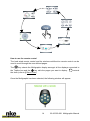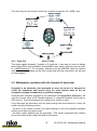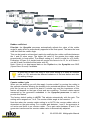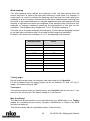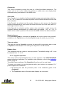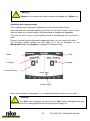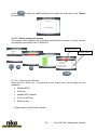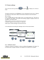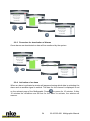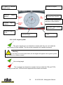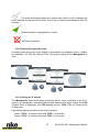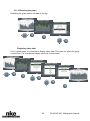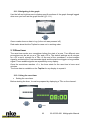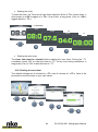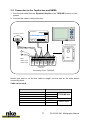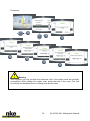
1
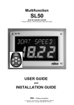
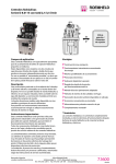
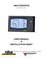
MULTIGRAPHIC Item number: 90-60-359 USER MANUAL & INSTALLATION SHEET V2.0 Zi de Kerandré – Rue Gutemberg – 56700 – HENNEBONT – FRANCE www.nke-marine-electronics.com +33 297 365 685 1 OVERVIEW ......................................................................................................... 4 2 OPERATION ....................................................................................................... 4 2.1 KEY DESCRIPTIONS............................................................................................. 4 2.2 MENU PAGE ....................................................................................................... 6 2.3 PAGE BUILDING WIZARD ...................................................................................... 7 2.4 DISPLAY PAGES ................................................................................................ 13 2.4.1 Page 4+4 ................................................................................................ 15 2.5 MULTIGRAPHIC OPERATION WITH THE GYROPILOT 2 PROCESSOR ......................... 15 2.5.1 Pilot Modes ............................................................................................. 18 2.5.2 Pilot settings ........................................................................................... 20 2.5.3 Gyropilot operation ................................................................................. 23 2.5.4 Pilot setup saving and recall ................................................................... 28 2.5.5 Pilot alarm ............................................................................................... 29 2.6 OPERATION OF THE MULTIGRAPHIC AS MULTIFUNCTION DISPLAY .......................... 30 2.6.1 Edit an existing page .............................................................................. 30 2.7 SETTING PARAMETERS ...................................................................................... 32 2.7.1 Display settings....................................................................................... 32 2.7.1.1 Backlighting ..................................................................................... 33 2.7.1.2 Setting Night and Day modes .......................................................... 33 2.7.1.3 Display’s Standby timing.................................................................. 35 2.7.1.4 Locking the keypad .......................................................................... 35 2.7.2 Data logging: “stripcharts” settings ......................................................... 36 2.7.3 Language selection................................................................................. 36 2.7.4 Unit selection .......................................................................................... 37 2.7.5 Maintenance ........................................................................................... 37 2.7.5.1 Multigraphic node address in the Topline system ............................ 37 2.7.5.2 Auxiliary inputs ................................................................................ 38 2.7.5.3 Topline Instrument system............................................................... 40 2.7.5.4 Firmware.......................................................................................... 41 2.7.5.5 Memory............................................................................................ 41 2.7.5.6 Simulator ......................................................................................... 41 2.7.5.7 Autotest ........................................................................................... 42 2.8 SENSOR SETTINGS ........................................................................................... 44 2.8.1 Calibration wizard ................................................................................... 44 2.8.1.1 Apparent Wind Angle calibration wizard .......................................... 45 2.8.1.2 Boat speed calibration wizard .......................................................... 46 2.8.2 Compass auto-adjustment ...................................................................... 47 2.8.2.1 Auto-adjustment principle ................................................................ 47 2.8.2.2 Compass auto-adjustment procedure .............................................. 47 2.8.2.3 Compass deviation table ................................................................. 48 2.8.2.4 Compass adjustment wizard ............................................................ 49 2.8.3 Drift angle ............................................................................................... 50 2.8.4 Sensors access code.............................................................................. 51 2.9 ALARMS SETTINGS ............................................................................................ 52 2.9.1 Alarm setting procedure .......................................................................... 53 2.9.2 Procedure for Alarm setting .................................................................... 53 2.9.3 Procedure for deactivation of Alarms ...................................................... 54 2.9.4 Activation of an alarm ............................................................................. 54 2 33-60-359-001 Multigraphic Manual 2.10 A.I.S. PAGE .................................................................................................. 55 2.10.1 A.IS. targets symbol ............................................................................ 56 2.10.2 Setting the radar-like scale .................................................................. 57 2.10.3 Setting A.I.S. alarms ........................................................................... 57 2.10.4 Collision avoidance calculation ........................................................... 58 2.10.5 Dangerous targets list ......................................................................... 59 2.10.6 Monitoring the fleet.............................................................................. 59 2.11 GRAPHS DISPLAY .......................................................................................... 60 2.11.1 Change the graph scale ...................................................................... 61 2.11.2 Resetting the graph ............................................................................. 62 Displaying other data ......................................................................................... 62 2.11.3 Navigating in the graph ....................................................................... 63 2.12 RACE TIMER ................................................................................................. 63 2.12.1 Using the race timer ............................................................................ 63 2.12.2 Setting the race timer .......................................................................... 64 2.13 PERFORMANCE FUNCTIONS ........................................................................... 65 2.13.1 Calculation of the current .................................................................... 65 2.13.2 True wind tables .................................................................................. 65 2.13.2.1 True wind angle table ...................................................................... 66 2.13.2.2 True Wind Speed table .................................................................... 67 2.13.2.3 Activating the true wind tables ......................................................... 68 2.13.2.4 Resetting the tables ......................................................................... 68 2.13.3 Statistics for the last hour .................................................................... 68 2.13.4 Boat’s parameters ............................................................................... 68 2.14 REGATTA PAGE ............................................................................................. 69 2.14.1 Presentation of the Regatta page........................................................ 69 2.14.1.1 Set the start line............................................................................... 72 2.14.2 Description of the upwind screen ........................................................ 73 2.15 INSTRUMENTS CALIBRATION ........................................................................... 74 2.15.1 Introduction ......................................................................................... 74 2.15.2 Calibrations order ................................................................................ 74 3 INSTALLATION ................................................................................................ 75 3.1 3.2 3.3 3.4 3.5 3.6 3.7 3.8 PACKING LIST. THE MULTIGRAPHIC COMES WITH: ................................................ 75 SUGGESTED SPARE PARTS LIST ......................................................................... 75 BEFORE INSTALLING CHECK............................................................................... 75 BULKHEAD INSTALLATION .................................................................................. 76 CONNECTION TO THE TOPLINE BUS AND NMEA .................................................. 77 NODE ADDRESS FOR THE MULTIGRAPHIC............................................................ 78 CONNECTING TO A NMEA SOURCE AND CONFIGURATION..................................... 78 INSTALLATION AND CONFIGURATION OF THE GYROPILOT ...................................... 78 4 MULTIGRAPHIC SPECIFICATIONS ................................................................ 80 5 EVENTS MESSAGES ....................................................................................... 81 3 33-60-359-001 Multigraphic Manual 1 OVERVIEW Thank you for purchasing the nke Multigraphic. The Multigraphic features a 5.7 inch colour screen. A transflective polarizer enhances daylight reading and integrated LED backlighting ensures clear readability at night. The backlight intensity can be automatically adjusted or user adjusted. The Multigraphic is a multifunction device allowing: Control of the nke Gyropilot2 or Pilote HR Display of data from the sensors connected to the Topline bus in digital, analogue or graphic formats and access to setup parameters and alarms. Display and processing of A.I.S. target data in a 12 mile range for collision avoidance, providing there is an A.I.S. receiver connected. Interface to NMEA 183 devices to provide relevant data to the Topline bus. 2 OPERATION The Multigraphic offers 10 buttons to control the display, access the menus and control the autopilot. 2.1 Key descriptions PAGE OK CURSER PAD AUTOPILOT CONTROL AUTO STOP MOB 4 33-60-359-001 Multigraphic Manual PAGE Successive presses will scroll through the pre-set data pages, the pilot page and the setting page. Press and hold (at least 3 seconds) to open the Menu page. OK A single press confirms the current selection, or opens specific setup features on some pages. Press and hold (at least 3 seconds) to open the settings page for backlighting, keyboard lock and stand-by mode. Cursor pad Use for the selection of pages and menu options. Autopilot control Use to control the autopilot’s course in 1° or 10° increments to Port or Starboard. Press and hold the 10° to tack. AUTO Single press to engage the autopilot. Press and hold this key to go directly to the Pilot Mode menu. STOP Single press to disengage the autopilot. Mob Press and hold to activate the man Over Board function on the Topline bus. 5 33-60-359-001 Multigraphic Manual 2.2 Menu page When the Multigraphic is used for the first time it displays a screen with a menu providing access to: the page builder function the sensor settings the alarm settings the pilot settings the Performance page setup 6 33-60-359-001 Multigraphic Manual the Multigraphic parameters Press the cursor pad’s arrows « left » and « right » to scroll through the menu icons for selection. 2.3 Page building wizard The Multigraphic has been designed to allow the user to customise pages. 10 pages can be set up according to the user’s preference with the first 5 pre-set to default settings. 7 33-60-359-001 Multigraphic Manual To build a page, first select the « Page » icon in the menu: Press once, the following screen appears: 8 33-60-359-001 Multigraphic Manual Select the page you want to build or edit with the up and down arrows pages are grayed out. Once you have made your selection, confirm with . Empty . Page format You can choose between different layouts for the page. Press , a list will appear. Select the screen layout template with the « up » and « down » arrows on the pad. , depending on the format you wish to display on the page. 9 33-60-359-001 Multigraphic Manual The following page layout templates are available: 1 line 2 lines 4 lines 4 lines 1+1 page A.I.S. data 3 lines 6 lines Waypoint page 3 lines 4+4 page XTE page Regatta page Once you have made a choice, press to confirm. 10 33-60-359-001 Multigraphic Manual Edit a page This setting selects the data that will be displayed on the selected page FOLLOWING to accept the current data in that selected part of the screen (only for multiple line pages) and go to the next page partition. MODIFY to change the information and the colour in which it will be displayed by selecting from a list. FINISH to accept the page and save the settings. Note: Some partitions of the page can display the information in analogue, graphic or digital format. The following is an example of a page containing an analogue display: Once the page has been built a window opens allowing you to save and rename the page. 11 33-60-359-001 Multigraphic Manual Press « OK » to save the page. Select Name with the pad and press the OK button to access the virtual keyboard. Use the pad keys to select letters and press the action for each entry. to confirm your choice. Repeat Toggle between numbers and letters. Caps lock. Delete last digit Enter, to confirm the name and save the page. 12 33-60-359-001 Multigraphic Manual Displayed The new page is visible by default. Press to hide the page. Unhidden Hidden . Edit name Edit the page name with the virtual keyboard. 2.4 Display pages Scroll through the build pages, the pilot and menu pages by pressing the button with successive presses. 13 33-60-359-001 Multigraphic Manual How to use the remote control The hard wired remote control and the wireless multifunction remote control can be used to scroll through the user defined pages. The key selects the Multigraphic display amongst all the displays connected to the Topline bus and the key calls the pages you want to display. the timer (refer to § Race Timer). Ent controls Once the Multigraphic has been selected, the following window will appear: 14 33-60-359-001 Multigraphic Manual The other keys on the remote control are not active except for the « MOB » key. 2.4.1 Page 4+4 This page toggles between 2 groups of 4 functions. It can also be used to display data coming from racing software via the NMEA input once it has been set up (refer to « NMEA settings »). For example, software such as ADRENA feeds the system with 8 functions depending on the race course legs and this information can be read on these pages. 2.5 Multigraphic operation with the Gyropilot 2 processor Gyropilot is an automatic pilot designed to steer the boat. It is intended to assist the helmsman and should never be used without state of the art navigation equipment handled by a qualified navigator. Once the pilot has been engaged by the helmsman the Gyropilot 2 processor will save the current value of the relevant channel: ie. magnetic heading, wind angle or GPS course. This value becomes the reference for course to steer. From that point the processor uses the data coming from the sensors to control the rudder using the following criteria: - the error to the course to steer, from data coming in from the compass (compass mode) or the wind unit (wind mode). - the boat motion delivered by the gyrometer. This sensor measures boat rotation due to the action of the rudder, the wind or the waves. 15 33-60-359-001 Multigraphic Manual The correction value is linked to: The error from the course to steer, The gain value, The boat speed (the correction factor is opposite to the boat speed. i.e. with a very low boat speed the correction factor is high, and with no boat speed the Gyropilot will not perform). Warning: Never leave the helm unattended. The helmsman has responsibility for keeping an efficient watch and to be ready to act in case of any event affecting the route of the boat. He must be ready to disengage the pilot and control the helm at any time. 16 33-60-359-001 Multigraphic Manual Useful buttons for controlling of the Gyropilot Press once to engage the pilot on the current course relevant to the pilot mode selected. In compass mode it will be the compass heading at the time you press the button and in wind mode it will be the wind angle at the time you press the button. Press and hold this key (>3s) to go directly to the Pilot Mode menu. Press once to disengage the pilot and take the helm back under manual control. Press once to change the course to steer by +1° Press once to change the course to steer by -1° Press once to change the course to steer by +10° Press and hold for automatic tack from starboard tack or gybe from port tack. Press once to change the course to steer by -10° Press and hold for automatic tack from port tack or gybe from starboard tack. Press the up and down arrows to adjust the gain from 1 to 9 and press OK to confirm. Press this button for access to the pilot’s mode and settings. 17 33-60-359-001 Multigraphic Manual Gyropilot page Gain value adjustable with the up and down arrows on the pad Access to the pilot mode with Sensor identification and value related to the pilot mode. Course to steer Rudder indicator angle Press « OK » to access the pilot mode and settings. Press « page » cancel the last action. to 2.5.1 Pilot Modes Select the pilot mode as follow: + + 18 33-60-359-001 Multigraphic Manual Press and hold this key (>3s) to go directly to the Pilot Mode menu. This shortcut is available from any page True Wind mode This mode requires a speed sensor, a compass sensor, a wind sensor and the software add-on « true wind ». Once this mode has been selected the pilot steers the boat to a set true wind angle as calculated by the processor. The true wind mode is particularly well adapted to downwind conditions in waves. These are the conditions where the nke pilot demonstrates its true capability. If apparent wind was used you would get the following issues: - The boat sails down the wave and apparent wind speed increases, the apparent wind angle decreases: it is a header, the pilot bears away to maintain the wind angle it is set to steer to. - The boat sails up the wave and apparent wind speed decreases, the apparent wind angle increases: it is a lift, the pilot luffs up to maintain the wind angle it is set to steer to. As a result, in waves the apparent wind mode is not efficient and it is better to select the compass mode to keep a straight course. With true wind mode the pilot steers the boat on a straight course keeping the optimum wind angle in the waves. The wind angle to steer is not affected by boat speed variations. While sailing solo it is very efficient to leave the pilot to steer the boat and focus on sails trim (just watch power consumption). True wind software add-on A code is required to activate the true wind mode function. Please contact your nke dealer to get this code. The code number is linked to each Gyropilot 2 processor, your dealer will need your processor’s serial number to issue the code for the software add-on. This serial number can be found on a label on the processor itself or in the true wind menu of the Multigraphic. Activation of the true wind add-on: The hexadecimal code is entered with the virtual keyboard. Once the function is activated the little padlock symbol will turn open and green. 19 33-60-359-001 Multigraphic Manual + + + Apparent wind mode This mode requires a speed sensor, a compass sensor and a wind sensor. With the apparent wind mode the pilot uses data from the mast head unit through the Topline bus to steer the boat on a set apparent wind angle. This mode is mainly used while sailing upwind. Compass mode This mode requires a speed sensor and a compass sensor. With the compass mode the pilot uses the compass heading data from the Topline bus to steer the boat on a set heading. Rudder mode The rudder mode allows the rudder to be set at a fixed angle. The value can be between – 35° and + 35° to the mid-ship position. Autopilot in GPS mode In GPS mode the Gyropilot steers the boat to a route provided by the GPS or the navigation software connected to the NMEA input of your Topline system. 2.5.2 Pilot settings Select the pilot’s settings page: 20 33-60-359-001 Multigraphic Manual + + + Rudder coefficient Principle: the Gyropilot processor automatically adjusts the value of the rudder angle to apply which is proportionally opposite to the boat speed. The faster the boat sails the lower the rudder angle. This can be tuned to achieve best results by modifying the rudder coefficient between the 1 and 53 value range. The higher the value is, the greater the rudder angle proportionally to boat speed. The default setting is 6, which is valid for a 30 footer. Examples: a Figaro 2 or similar boat will require this factor to be 15, for a 60 footer it can be 20 and a multihull will be better with 30. Note: if there is no boat speed data on the Topline bus, the Gyropilot uses SOG (Speed Over Ground) if available. A good way to learn the effect of this value setting is to enter an extreme value, i.e. 50, and note the different behaviour of the boat before and after the setting change. Counter rudder / gain When you are steering you will often apply “counter rudder” by moving the rudder to the opposite direction allowing the heading to be maintained without overshoot. The pilot can be set up to control the boat in a similar way and the importance of this feature will depend on the type of boat and sea conditions. The boat rotation speed measured by the gyrometer embedded in the Gyropilot processor is used to provide this feature. The factory default setting is AUTO. This adjusts automatically with the gain. The setting value ranges from 1 to 9. The counter rudder angle is the lowest at 1. Note that when the counter rudder setting is on AUTO, the counter rudder action is dependent on the gain setting. For a rudder gain between 1 and 3, the gyrometer is not active and there is no counter rudder. For a gain value between 4 and 9, the gyrometer is active and the counter rudder value is automatically adjusted. 21 33-60-359-001 Multigraphic Manual Wind damping The wind damping value adjusts the treatment of the raw data coming from the sensor and how it is used by the pilot while steering in wind mode. For example, in rough seas it is useful to increase the damping value because the mast head unit is subjected to a lot of extreme movements and the wind measurements resulting from this need to be treated differently to maintain appropriate pilot performance and sea keeping. In light wind and quiet sea conditions a low damping value will allow a finer response to changes measured optimising the performance of the pilot for the conditions. The damping value ranges from 1 to 9. The default setting is 1. The value set to 0 means automatic wind damping. In that case the damping is linked to the wind vane oscillations with 0.5 seconds for each degree of oscillation. Example: if the wind vane oscillation is +/-10°, the damping is 10 seconds. Damping value effect L=0 automatic L=1 1s L=2 2s L=3 4s L=4 8s L=5 16 s L=6 32 s L=7 64 s L=8 128 s L=9 256 s Tacking angle Set the tacking angle value for automatic tack performed by the Gyropilot. For the compass mode the tacking angle can be set between 70° and 115° (by 5° steps). The default setting is 100°. Tack speed The speed at which tacks are performed by the Gyropilot can be set from 1° per second to 32° per second. The default setting is 9° per second. Man Over Board The Man-Over-Board function can be activated from any MOB button on a Topline display or a wireless remote control (Gyropilot, Multifonction or Crew) if the MOB function has been set. This function works with two selectable modes: Crew and Solo. 22 33-60-359-001 Multigraphic Manual Crew mode This mode is selected to assist the crew for a Man-Over-Board manoeuvre. The system will not act on the rudder but activate an audible alarm and display dead reckoned bearing and distance to the MOB event. Solo mode If the Gyropilot is in stand-by it will automatically engage and push the rudder by + 40° or – 40°, in relation to the rudder’s position at the moment the MOB function has been activated. If the Gyropilot is activated and the system features a wind sensor, the Gyropilot switches automatically to wind mode and steers the boat up to the wind (with a 0° wind angle course to steer). If the Gyropilot is activated and the system does not feature a wind sensor, the Gyropilot switches automatically to rudder mode and applies + 40° or – 40°, in relation to the rudder’s position at the moment the MOB function has been activated. Speed reference If the true wind mode is activated the Gyropilot will use the speed over ground (if available on the Topline bus) or the boat speed through the water, at your choice. Time out setting This sets the time the Gyropilot can steer the boat with the gyrometer data in case of Topline bus data dropout. The setting can range from 0 to 60 seconds. Rudder offset This calibration sets the rudder to mid-ship position. The default setting is 0°. It can be adjusted from –3° to +3. 2.5.3 Gyropilot operation This section of the manual describes the use and operation of the MULTIGRAPHIC once installed and calibrated. For installation and calibration, refer to the installation section, page 70. The default factory settings of the Gyropilot will perform well on most boats. To power your system on use the general switch panel where two separate 12 V power supplies are installed for: The power drive and the processor (refer to the installation guide of the Gyropilot2) The Topline bus where all sensors and displays are connected. 23 33-60-359-001 Multigraphic Manual Warning: Always turn the power drive and processor on before the Topline bus. Operation with compass mode The compass mode requires a compass sensor and a boat speed sensor. Steer the boat onto a suitable heading, allow time for the boat to settle on this course with the rudder on mid-ship position and press Auto to engage the Gyropilot. The pilot will steer to the current heading which is automatically set as course to steer. Return to manual steering by pressing stop once when you are ready at the helm. The following graphic shows the pilot page as it will be displayed on the Multigraphic when the Gyropilot is engaged in compass mode. Mode Gain Pilot type Compass Course to steer Rudder angle Note: when the pilot is disengaged «---» is displayed instead of the course to steer. Warning: The Auto button engages the pilot and the Stop button disengages the pilot. Make sure the pilot is disengaged before turning the power supply off. 24 33-60-359-001 Multigraphic Manual Operation with Apparent Wind mode The compass mode requires a compass sensor, a boat speed sensor and a wind sensor. The apparent wind mode uses data from the mast head unit made available on the Topline bus to steer the boat on a set Apparent Wind Angle. This mode is mainly used while sailing upwind. The following graphic shows the pilot page as it will be displayed on the Multigraphic when the Gyropilot is engaged in Apparent Wind mode. Gain Mode Pilot type Apparent Wind Angle AWA to steer Rudder angle 25 33-60-359-001 Multigraphic Manual Operation with True Wind mode (See § “True wind mode”) This mode requires a speed sensor, a compass sensor, a wind sensor and the software add-on « true wind ». Once this mode has been selected the pilot steers the boat to a set true wind angle calculated by the Gyropilot processor. The following graphic shows the pilot page as it will be displayed on the Multigraphic when the Gyropilot is engaged in True Wind mode Gain Mode Pilot type True Wind Angle TWA to steer Rudder angle Operation in Rudder mode The rudder mode allows the rudder to be set at a fixed angle. The value can be between – 35° and + 35° to the mid-ship position. This mode can be used to check the drive unit or just to lock the rudder in a given position. 26 33-60-359-001 Multigraphic Manual The following graphic shows the pilot page as it will be displayed on the Multigraphic when the Gyropilot is engaged in Rudder mode Mode Gain Pilot type Rudder angle Rudder angle lock Rudder angle Using the GPS mode In GPS mode the Gyropilot steers the boat to a route provided by the GPS or the navigation software connected to the NMEA input of your Topline system. To achieve this, the GPS or the navigation software must feed the system with the following NMEA sentences: - $xxXTE : cross-track error and - $xxBWC : bearing and distance to waypoint (DTW and BTW) or - $xxRMB : XTE, latitude, longitude and bearing and distance to waypoint (DTW and BTW as minimum data). Gain value Pilot Mode Pilot Type Graphic representation of the cross-track error Bearing to Waypoint Distance to Waypoint Speed Ground Over Cross-track error 27 Course Over Ground 33-60-359-001 Multigraphic Manual WARNING: Make sure your position is as close as possible to the route before engaging the pilot. When Cross-track Error is greater than 0.4 nm, the Gyropilot will apply a 45° angle to the route bearing. When reaching the WAYPOINT the pilot triggers an audible alarm, keeps the compass heading and quits the GPS mode. The skipper must check that the route is safe and that the bearing to the next WAYPOINT is correct before pressing AUTO to resume the GPS mode. This has to be repeated for every WAYPOINT. WARNING: Your GPS or navigation software which is connected to the pilot may be able to activate the next waypoint automatically. In that case the pilot will follow the route’s legs accordingly. 2.5.4 Pilot setup saving and recall Up to 10 pilot setups can be saved and used at any time. For example, you can save a setup for upwind conditions and another one for downwind. Saving a pilot setup: + + 28 33-60-359-001 Multigraphic Manual Recall a pilot setup: + + 2.5.5 Pilot alarm You can set two different alarms. One is for wind direction variation and another one for low voltage. - The first alarm is called “Wind/Head’ in the system. It measures variations in wind direction when the pilot is in compass mode or heading in wind mode. A value can be set up for the system to trigger the alarm. The default value is 15°. The alarm will sound when the wind angle variation is greater than the set value for more than 30 seconds in compass mode and when the heading variation is greater than the set value for more than 30 seconds in wind mode. The Multigraphic will display a message and sound beeps. - The second alarm is called “Power Battery” in the system. It measures variations in the charge level of the battery powering the pilot’s drive unit. The default value is 8 V DC The alarm is triggered when the voltage is lower than the set value. The Multigraphic will display a message and sound beeps. 29 33-60-359-001 Multigraphic Manual Alarm setup procedure for the pilot + + + + 2.6 Operation of the Multigraphic as multifunction display Multigraphic is a multifunction display from the TOPLINE range of products. It connects to the TOPLINE bus on your system and displays all data available on the bus. The keyboard, curser pad and scroll down menus make all aspects of the system easy to use. Multigraphic facilitates control and use of your Topline system. 2.6.1 Edit an existing page Once a page has been built (see paragraph 2.3), it can be edited to show temporary or permanent changes. Temporary modification Temporary modification of a page allows data of your choice to be displayed without saving a new layout. 30 33-60-359-001 Multigraphic Manual Example: on the first page choose the bus Voltage instead of COG. + + + This modification has not been saved and the previous layout will return the next time the system is powered on. Saving a modification to a page You can edit a page and save modifications permanently. Example: on the first page now choose to display apparent wind angle instead of the bus Voltage and save this new configuration. + + + + + + + 31 33-60-359-001 Multigraphic Manual This page configuration can be saved or renamed and saved as a new page. 2.7 Setting parameters Press and hold «Parameters» page.* to display the main menu in which you select Use the up and down arrows of the pad to select and for the to confirm. 2.7.1 Display settings The Display Settings menu gives access to: The Display Mode The Daylight Mode settings The Night Mode settings The Stand-by timing 32 33-60-359-001 Multigraphic Manual 2.7.1.1 Backlighting The backlightighing can toggle automatically between Night and Day settings, driven by a light sensor, or can be manually set. Backlight settings can be adjusted as required for each Multigraphic independently. Backlight setup process: + + + Auto: Backlighting toggles automatically between Night and Day settings, driven by a light sensor. The Backlight intensity and the Skin are those set for each Mode. Day: Backlighting is on with the light intensity and the Skin set for Day Mode. Night: Backlighting is on with the light intensity and the Skin set for Night Mode. Whatever page is currently displayed press and hold « OK » for 3 seconds to access directly to the backlight levels settings. There are 20 levels of Backlighting. 2.7.1.2 Setting Night and Day modes Setting procedures are identical for Day mode and Night mode. 33 33-60-359-001 Multigraphic Manual Backlight intensity setting: + + + Skin settings + + + You can choose between 7 Skins for Day and Night modes. The default Skins are white for Day and black/red for night. 34 33-60-359-001 Multigraphic Manual Some skins are more appropriate than others, depending of the reading angle. 2.7.1.3 Display’s Standby timing A time can be set up to 30 minutes. When the selected time is reached the display will be put in a “sleep mode” for power saving. The Multigraphic will keep working and the screen can be resumed with the simple press of any key or selecting the display on a remote control. Setting the Display’s Standby timing + + + + Press and hold the “OK” key for 3 seconds to enter the Display Standby setting menu. This can be done from any page. 2.7.1.4 Locking the keypad Press and hold “OK” to enter the setting. 35 33-60-359-001 Multigraphic Manual Once Lock Keypad is activated all keys are inactive and a press on a key pops up an invite to unlock the keypad. + 2.7.2 Data logging: “stripcharts” settings 4 different sets of data can be logged simultaneously over a 48 hour period with a 15 seconds log rate. The logged data can be displayed on stripcharts on the « Multigraphic ». « stripcharts » settings process: + + + 2.7.3 Language selection Your Multigraphic can be set to display menus in various languages. 36 33-60-359-001 Multigraphic Manual Language setting process: + + 2.7.4 Unit selection The Multigraphic can be set to use various units for boat speed, depth, air temperature, sea temperature and wind speed. Depending on the information selectable units are « knots », « meters per second », kilometres per hour », degrees Celsius » and « degrees Fahrenheit ». Units setting process: + + + 2.7.5 Maintenance 2.7.5.1 Multigraphic node address in the Topline system In this menu you have to give a Topline address to the Multigraphic. With address n°1 it will be considered as « Master » and manages the whole system. If there is already a Master », the Multigraphic will get an address different from 1 and it will 37 33-60-359-001 Multigraphic Manual behave as « Slave ». This process is carried out automatically: if there is no « Master » in the system, the Multigraphic will automatically be selected as « Master ». Systems with an existing « Master » will automatically deliver a « Slave » address to the Multigraphic. There is always the possibility to reset the address to 0 (no address). Note: the Multigraphic comes with a factory default setting as n°0. It has no address and it cannot work with your system. Giving an address to the Multigraphic is the very first setting to do once the display is connected to the Topline bus and the installation complete. Multigraphic address process: + + Resetting the address: + + 2.7.5.2 Auxiliary inputs 2.7.5.2.1 Console The Multigraphic has a NMEA console allowing NMEA input data to be displayed. 38 33-60-359-001 Multigraphic Manual Access to the NMEA console: + Or 2.7.5.2.2 NMEA settings The Multigraphic features a NMEA0183 input which allows any compatible instrument (GPC, PC…)to be connected. This port converts any NMEA incoming data to Topline channels if they do not already exist on the Topline bus. The data will be used by the Topline system. Baud rate is automatically detected between 4800 or 38400 Bauds. Note: NMEA data coming from an A.I.S receiver connected to the Multigraphic NMEA input is directly available on the Multigraphic and does not require set up. NMEA input settings: + + + All NMEA channels are activated by default. You can choose to inhibit some channels. This is done by selecting the chosen channel and pressing . Here, Speed Over Ground is inhibited 39 33-60-359-001 Multigraphic Manual Press to finish the NMEA settings and update the channels on the Topline bus accordingly. 2.7.5.3 Topline Instrument system This system menu displays the properties and software versions of all the sensors and displays connected to the Topline bus. Display’s nodes Software Version + 2.7.5.3.1 Utility for the WIFI box When the nke “WIFI box” is connected to the Topline bus, the following can be displayed: Editable SSID WPA key editable WIFI channel IP for the WIFI box WIFI box port Please refer to the WiFi Box manual. 40 33-60-359-001 Multigraphic Manual 2.7.5.4 Firmware This page displays the Multigraphic software version and date of issue. Display the firmware: + 2.7.5.5 Memory This menu allows the user to reset the Multigraphic to factory settings. Reset the Multigraphic + + 2.7.5.6 Simulator There is a simulator available in the Multigraphic. Once activated, it sends random data to the Topline bus and the symbol working in simulation mode. 41 is shown to highlight that the system is 33-60-359-001 Multigraphic Manual Simulator menu: + 2.7.5.7 Autotest Autotest is useful to check the Multigraphic. This procedure verifies the following functions step by step: keys colour display light sensor (vlight), internal temperature sensor, power supply. backlighting memory Topline bus NMEA input and output (connect the yellow and red wires together for that operation). Data logged in cookies Proceed to each step by confirming with « OK ». Once the auto-test is complete the Multigraphic restarts. 42 33-60-359-001 Multigraphic Manual + All keys 43 33-60-359-001 Multigraphic Manual 2.8 Sensor settings Go to the main menu by pressing page. and select to display the « sensors » All sensors connected to the Topline bus can be calibrated from this menu. Settings are different for each sensor. Refer to the sensor’s manual for more information. Main settings: Filter: the filter takes the data average value to set a data refresh rate. The filter set for apparent wind speed, boat speed and heading (Regatta compass) affects the autopilot’s “True Wind” mode. Offset: applies a correction to data for some sensors. Coefficient: applies a correction factor for calibration. Reset: back to default settings of the selected sensor. In this example we are setting the damping value for a boat speed sensor: + + + 2.8.1 Calibration wizard Calibration wizards are available to help you calibrate the apparent wind angle, the boat speed and a fluxgate compass (not available for the REGATTA compass). 44 33-60-359-001 Multigraphic Manual wind 2.8.1.1 Apparent Wind Angle calibration wizard Sail 4 legs upwind to measure the average wind angle on each tack. A wind vane offset will be calculated and applied to correct the Apparent Wind Angle. Apparent Wind Angle values must be similar from one tack to another (+-1°) when the calibration is correct. If this is not the case, the wind may have shifted, or the crew cannot sail with the same angle on each tack upwind! stop start stop start stop start stop start Calibration of the Apparent Wind Angle + Sail once again on starboard tack and port tack to fill the table for fine calibration. Once this is done, you will be invited to save the new offset value. 45 33-60-359-001 Multigraphic Manual + 2.8.1.2 Boat speed calibration wizard The boat speed is calibrated with the speed over ground as reference. You have to sail 0.5 nM on a constant heading and then sail back (180°) the same distance. The new calibration is processed from the current calibration value already saved (there is no need to reset the calibration value to 1). The COG (Course Over Ground) function must be displayed on the Topline network to achieve the boat speed calibration. Boat speed calibration + + + 46 33-60-359-001 Multigraphic Manual This page displays the current calibration value (old correction), the new calibration value (new correction), the factors calculated from the runs (ratio FW/BW) and the correction factor for boat speed. 2.8.2 Compass auto-adjustment Some magnetic deviation errors are unique to each boat, due to the magnetic environment. An auto-adjustment of the compass is required to make the compass learn this environment and achieve acceptable accuracy. 2.8.2.1 Auto-adjustment principle To achieve this a swing procedure is required which consists of turning the boat through a complete and perfect 360° turn clockwise at a constant rate of turn and boat speed. During this procedure the compass builds its own deviation curve table. Corrections will be applied accurately from 0 to 359° in the sectors of sluggishness and unsteadiness. 2.8.2.2 Compass auto-adjustment procedure Conditions to achieve a successful auto-adjustment manoeuvre: - Steady waters without current. Safe distance from any source of magnetic field such as cargo ships. Safe area for free manoeuvre in a 5 boat length radius. Motor at constant low speed (2 or 3 knots). ATTENTION: the auto-adjustment operation needs to be carried with a lot of care. Motor the boat at 2 or 3 knots in a perfect circle. For the Regatta compass, the compass swing must be performed in less than 5 minutes. Providing you match these conditions the auto-adjustment will be successful. 47 33-60-359-001 Multigraphic Manual + + While swinging the fluxgate, or Regatta compass, you can display the Course Over Ground in a window to show the progress of the manoeuvre. In the case of the Regatta compass without COG data on the bus the progression will not be displayed and you will need to follow the procedure from the bowl compass at the helm. Once the auto-adjustment has been completed a message will be displayed telling you that the operation was successful or not. 2.8.2.3 Compass deviation table Can be used solely for the fluxgate compass This method can be used to set up the fluxgate compass when it is not easy to complete the automatic compensation. The deviation curve needs to be set at points every 30°. Each point can be determined using leading lines, or by comparing headings against a calibrated compass with the results being used to fill the correction table with the measured values. How to fill the correction table 48 33-60-359-001 Multigraphic Manual + + + + + When this table is completed your compass is corrected for the deviation curve. 2.8.2.4 Compass adjustment wizard This method can only be used with the fluxgate compass It consists of sailing the boat on the nke compass heading (+/-5°), comparing this heading with the magnetic heading over the ground and noting the value every 30° to determine the values for the correction table. Compass adjustment procedure + + + + + Press “OK” to save the new correction. You can highlight “Abort” and press “OK” if you want to cancel a correction. Repeat this operation every 30° to fill the whole 49 33-60-359-001 Multigraphic Manual correction table. The compass will have its deviation curve implemented once this table is completed. 2.8.3 Drift angle Drift angle is measured between the boat’s heading and its course. WIND Heading Course This value is used for true wind, VMG, corrected heading and current calculation. Therefore it must be calculated optimally. We use the following formula: The correction factor is linked to the hull shape and the boat’s performance. Lower values indicate higher performance The drift value is always applied whatever the navigation conditions. Therefore, it has to be an average value, valid for all weather conditions or alternatively, you can alter that value upon the wind strength. The drift angle for each boat speed and heel angle is shown with the polar tables supplied by your architect. Calculate the drift factors with the formula below, and determine the average value. Use a 10.0 factor if you cannot find the relevant data. i.e. the drift with 17° heel angle and 7 knots boat speed is: 10 x 17° / 72nds + 0° = 3.46° drift angle 50 33-60-359-001 Multigraphic Manual As an alternative to this formula, an offset value can be set to force the drift angle by setting the factor to 0 and entering the desired value of the drift angle as an offset. A maximum value can be set for the drift angle, i.e. with a 5° limit; the final result will never exceed 5° even though the data is still processed in the same way. Drift angle data processing procedure + + + + The procedure is the same for setting the maximum drift angle and the offset for drift angle. 2.8.4 Sensors access code The sensors access code is meant to protect all calibrations for the sensors connected to the Topline bus. Once activated, the access to the calibration menu is locked. Procedure for sensor access code setting: + + 51 33-60-359-001 Multigraphic Manual Procedure to unlock the sensor menu: + 2.9 Alarms settings Press and hold to display the main menu from which you select display the « Alarm » page. to Setting alarms allow keeping watch on the value of set channels. Once the set value is reached a message is displayed and an audible signal is emitted. For example, low and high values can be set for the Boat Speed channel. High alarm will be activated when the data reaches the set value and above. Low alarm will be activated when the data reaches the set value and below. Note that for channels with angle data such as magnetic heading or wind angle the alarms sub-channels are based on a value +/- x from a reference angle called “base alarm”. Setting alarms is an efficient way to monitor the TOPLINE system and the way your boat is sailing. 52 33-60-359-001 Multigraphic Manual 2.9.1 Alarm setting procedure In order to use alarms you must first select the data you want to monitor and then determine the low and high values or the base and ranges for angles. Once set up, the icon indicates the validation of the relevant channel. Here is an example of alarm setting for low value of the apparent wind speed: + + + + 2.9.2 Procedure for Alarm setting Once you have selected the data to watch the alarm system must be activated on the Topline bus. A status window will show before activation. 53 33-60-359-001 Multigraphic Manual + 2.9.3 Procedure for deactivation of Alarms Once alarms are deactivated no data will be monitored by the system. + 2.9.4 Activation of an alarm When an alarm is activated a window will appear showing which data is activating the alarm and an audible signal is emitted. The data for this channel is displayed in red on the relevant page of the Multigraphic. Press to pause for 10 minutes. If after 10 minutes the conditions are still met for the alarm to activate, the window will resume. 54 33-60-359-001 Multigraphic Manual 2.10 A.I.S. page A.I.S. (Automatic Identification System) is a worldwide system for exchanging information between ships and stations ashore. A.I.S uses dedicated VHF frequencies to automatically broadcast information such as ship’s identification, status, position and route. This information is available to any ship or traffic control station within the signal reception area. The NMEA input of the Multigraphic can be connected to an A.I.S. receiver to display A.I.S. targets and to calculate collision risks. Glossary: CPA (Closest Point of Approach) is the shortest distance to the meeting point of two vessels in approach. This is used to measure the collision risk. TCPA (Time Closest Point of Approach) is the time remaining until CPA (hours, minutes and seconds) 55 33-60-359-001 Multigraphic Manual N° MMSI or selected target’s name Selected bearing Selected distance Number of targets target’s Selected target’s Course Over Ground Selected target highlighted in red when in alert position. target’s Selected target’s Speed Over Ground Selected target’s CPA sélectionnée CPA’s bearing selected target for Selected target’s TCPA 2.10.1 A.IS. targets symbol The green targets are non-hazardous vessels and they are not inside the alert limits you have defined. The front arrow represents the vessels movement. Warning: If you have not set any alert limits, all the targets will appear with a green symbol, even those on a collision course. Non moving target The red targets are hazardous vessels that are inside the CPA and TCPA limits you have set. The front arrow represents the vessels movement. 56 33-60-359-001 Multigraphic Manual The white and striped targets are vessels from which no AIS message has been received for the last 90 seconds. These will no longer been displayed after 10 minutes. Selected target is highlighted by a frame. AIS Man Overboard 2.10.2 Setting the radar-like scale A display scale can be set-up for targets in accordance to navigation zones. 5 scales are available: 1M, 2M, 4M, 6M and 12M. The default setting of the Multigraphic is 12M. + + 2.10.3 Setting A.I.S. alarms The Multigraphic features an alarm processor which, once connected to an A.I.S. receiver or transponder, calculates bearing and distance of a target vessel, the CPA (Closest Point of Approach), the CPA bearing and the TCPA (Time to Closest Point of Approach). It generates alarms according to the level activated: Alarm if CPA < 6 nautical miles and TCPA < 30 minutes Alarm if CPA < 4 nautical miles and TCPA < 20 minutes 57 33-60-359-001 Multigraphic Manual Alarm if CPA < 2 nautical miles and TCPA < 15 minutes Alarm off + + The red circle represents the alarm zone. 2.10.4 Collision avoidance calculation The Multigraphic constantly scans messages received via the A.I.S. receiver/transponder. The unit will generate an alarm if a target is detected and its CPA and TCPA are both below the level defined. The relevant target will appear red. . Alarm principle 58 33-60-359-001 Multigraphic Manual The alarm has been set for « CPA < 4 Mn and TCPA < 20 minutes ». As a result, CPA being below 4 miles and the TCPA calculated value being below 20 minutes, the Multigraphic triggers an alert. 2.10.5 Dangerous targets list The list of targets representing a threat shows all targets that are in the alarm zone. They are sorted by threat level. For each of them the MMSI number, the bearing, the distance, the CPA and the TCPA are displayed. + + Any target can be selected from the targets list and pressing A.I.S. page. displays it on the 2.10.6 Monitoring the fleet A fleet list shows all A.I.S. targets sorted by distance from the closest. The targets that represent a threat are displayed in red. 59 33-60-359-001 Multigraphic Manual + + Any target can be selected from this targets list and pressing A.I.S. page. displays it on the 2.11 Graphs display Some data coming from the Topline sensors can be displayed as a graph. All data stored in the log can be displayed as a graph with a zoom function ranging from 5 minutes to 48 hours depending on the time they have been logged. Data which is not stored in the log can be displayed on a 5 minutes scale. When you build or edit a page a graph widget is shown for the data which can be displayed as a graph. 60 33-60-359-001 Multigraphic Manual + + + + + + + 2.11.1 Change the graph scale 8 scale levels are available for data which is stored in the log: 5 minutes, 20 minutes, 1 hour, 2 hours, 6 hours, 12 hours, 24 hours and 48 hours. Procedure to change the graphs scale: + + 61 33-60-359-001 Multigraphic Manual 2.11.2 Resetting the graph Resetting the graph erases the data in the log. + + Displaying other data From a graph page it is possible to display other data. This does not affect the page construction. It is a temporary display which will not be saved. + + + 62 33-60-359-001 Multigraphic Manual 2.11.3 Navigating in the graph Use the left and right arrows to display specific sections of the graph through logged data once you have set the graph’s scale (§ 2.11.1). Green marks show no data in log (ie the unit was powered off). Red marks show that the Topline bus was not in working order. 2.12 Race timer The race timer works as a countdown before the start of a race. Two different race procedures can be set up as « T1 » and « T2 ». The default settings are 8 minutes for « T1 » and 4 minutes for « T2 ». At the end of the countdown, a short audible signal is emitted at the 5 last seconds signal and the start time triggers a long audible signal. These audible signals are repeated by every display. Once the countdown reaches « 0 », the timer starts for the race time in hours and minutes. The timer data is available on the Topline for any display to repeat it. 2.12.1 Using the race timer Setting the race timer Before starting the timer, it must be prepared by displaying « T1 » on the channel. >3s 63 33-60-359-001 Multigraphic Manual Starting the timer To start the timer, the Timer must have been selected. When « T1 » counts down, a short press on « OK » toggles to « T2 ». At any time, a long press (>3s) on « OK » toggles back to « T1 ». T1 selected T2 T1 Starting the race timer The timer data must be selected before starting the race timer. During the “T1” countdown, press “OK” to reset the timer to “T2”. At any time during countdown, a long press (>3s) on “OK” resets the timer to “T1”. 2.12.2 Setting the race timer The default settings are 8 minutes for « T1 » and 4 minutes for « T2 ». Here is the procedure to set the timers to your own values: + + + + 64 33-60-359-001 Multigraphic Manual 2.13 Performance functions 2.13.1 Calculation of the current The Multigraphic will automatically calculate the current when it is set as a master. The following channels are created: Speed of measured current (in knots). Direction of measured current (in degrees True). The data can be displayed on the Multigraphic. Contrary to wind direction, which is measured as the bearing the wind is blowing from, the current’s direction is measured in the direction it is travelling towards. This value is a True Heading (geographic). The calculation of the current requires the following channels to be active: Magnetic Heading Magnetic Variation Heading Over Ground Boat speed Drift angle The primary sensors must be correctly calibrated to ensure reliable and accurate information. 2.13.2 True wind tables The data measured by the wind sensor placed on top of the mast, even when on a long carbon arm, is affected by the sails. The wind flow is disturbed around the sails and rig. This is called the “upwash”. This “upwash” affects the measured raw data measured for the calculation of the true wind direction. Therefore, the true wind direction may be different from one tack to another and the wind speed varies from upwind to downwind. The errors due to upwash can be repeated with sail configurations and wind speed combinations making it possible to apply corrections. A correction table can be filled for true wind speed and angle. Warning: The true wind correction tables only work with the HR or Carbowind sensors featuring the V2.5 (or newer) firmware. 65 33-60-359-001 Multigraphic Manual 2.13.2.1 True wind angle table The true wind angle table allows correction of the true wind angle value without researching the causes of angle’s errors. It corrects all repeatable errors (twist, flow over-speed downwind, sensor). The true wind data is calibrated by logging the true wind direction differences from one tack to another repeatedly. It is recommended that these calibration sessions are run from 5 to 50 knots in winds that are stable in direction. Starboard tack TWD 250° Port tack TWD 260° Heading 210° Heading 300° 10° 45° 45° TWD port tack > TWD starboard tack: Add half of the difference between the two True Wind Directions. + + + + Select the value to be corrected. Modify the value. The column on the left indicates the true wind speed in knots, the “V1” column is the correction to apply in degrees and the “A1” column indicates on which angle the correction will apply. The same pattern applies for “V2” and “A2” for sidewind and “V3” “A3” for downwind. 66 33-60-359-001 Multigraphic Manual 2.13.2.2 True Wind Speed table Even when placed one meter above the mast head on top of a carbon arm the wind sensor will measure a flow altered by the effects of the mainsail. When sailing downwind the mainsail causes an acceleration of the air flow at the mast head and when the boat is heeling the measurement of the wind will be altered. A calibration of the wind speed is required for all these reasons. Procedure for measurement: Hold the boat upwind at no boat speed and measure the average wind speed shown by the display. Then, while sailing at all wind angles log the wind speed shown on the displays. The average values can be used in the correction table. Always think about logging these values whenever you sail between 5 and 30 knots. + + + + The column on the left indicates the true wind speed in knots, the “V1” column is the correction to apply in degrees and the “A1” column indicates on which angle the correction will apply. The same pattern applies for “V2” and “A2” for sidewind and “V3” “A3” for downwind. Select the value to be corrected. 67 Modify the value. 33-60-359-001 Multigraphic Manual 2.13.2.3 Activating the true wind tables The corrections will be implemented once the true wind tables are activated. + + + 2.13.2.4 Resetting the tables The “RESET TABLE” command can be used at any time to reset the table to the default values. 2.13.3 Statistics for the last hour True Wind Direction, average of the true wind direction during the past hour. Wind shift, calculation of the true wind direction standard deviation for the past hour. Average wind speed, average of the true wind speed data for the past hour. Gusts, calculation of the of true wind speed standard deviation for the past hour. Maximum Speed, maximum speed averaged on 12 seconds laps time. 2.13.4 Boat’s parameters Enter the relevant data for increased accuracy in the Regatta page. Tack Angle: enter the boat’s tack angle so the boat speed recovering after a tack can be displayed. Boat’s size: this data is used to calculate the distance to the starting line in boat’s lengths. GPS antenna’s distance to bow: this data is required to calculate the distance to the starting line in meters and the time to the starting line. 68 33-60-359-001 Multigraphic Manual 2.14 Regatta page 2.14.1 Presentation of the Regatta page A B C D E F G H A. Starting mode screen B. True Wind indicator This indicator gives a quick and accurate view of the true wind direction behaviour: o Value range o Current value o Average o Values variations’ standard deviation Description of the example featured in this page: 69 33-60-359-001 Multigraphic Manual The current wind direction is 7°magnetic, the left end is 0° and the right end is 29°. The average value is in the centre of the colour shading which covers the extend of the standard deviation of the wind shifts. We note that: The shading is centred, meaning that the variations between left and right are balanced. The shading is spread, meaning that the wind shift range is wide (the more stable the wind the narrower the shading). The pointer indicates the current value. It is on the left side of the shading, meaning a wind shift to the left. The pointer is shown as an average shift to the left The pointer is at 7° on the left side, but the display shows that there have been shifts further to the left! The data is processed for the past 5 minutes. C. Timer The timer can be set from the Regatta page. + A press on “OK” starts the count-down. A second press on “OK” resets the timer on T2. Warning The access to the Performance page is locked during the countdown from T1 to T2. 70 33-60-359-001 Multigraphic Manual D. Start line The committee boat is symbolized by the buoy on the right and the pin is the buoy on the left. The favourable side is green. In this example, it is the committee boat. 16° shows the favourable angle value. In this example the wind angle to the right side of the perpendicular to the line is 16°. By knowing the start line length, the MultiGraphic can calculate the gain to windward difference between both ends of the line. In this example, the 16° favourable side on the committee side of the line gives a 228 meters gain to windward for a 796 meters start line. This interesting information shows that the gain to windward grows considerably with the line length and favourable angle value. E. Distance to the line The distance to the line is displayed in meters and boat lengths. The value displayed is the distance between the line and the boats bow (not the GPS antenna’s location). The boat’s size and the distance between the GPS antenna and the bow must be entered in the system via the menu Performance Boat’s parameters. F. Start line’s length This is the distance between the committee and the pin in meters. G. Time to the line The remaining time to the line is calculated from the speed over ground, so that the effect of the current is taken in account. The time is displayed in seconds when it can be calculated. It is the time required for the boat to reach the line, given the current boat speed and heading. Should boat speed or heading change, the time to the line is updated. H. Start line orientation This is the bearing of the pin from the committee boat side given in True degrees. The variation must be added to get the Magnetic bearing. 71 33-60-359-001 Multigraphic Manual 2.14.1.1 Set the start line The start line’s ends can be entered using the GPS position (antenna) or bearing and distance. Entering the GPS position: Sail as close as possible to the mark at low speed and validate the position when the GPS antenna matches the marks position as much as possible. Enter a line end with GPS position + + Enter a line end with bearing and distance + + + + + 72 33-60-359-001 Multigraphic Manual 2.14.2 Description of the upwind screen The upwind screen automatically displays once the racing timer countdown is over or manually with the key A B C D E F A. Upwind screen B. True wind indicator After tacking, the true wind indicator toggles to a speed pick up indicator showing boat speed before tacking on the left and instant boat speed on the right. C. Magnetic heading D. Boat speed E. Distance to the mark n°1 F. Bearing to the mark n° 1 73 33-60-359-001 Multigraphic Manual Distance and bearing to the n°1 mark can be displayed with the distance and bearing to Waypoint channels of the Topline bus once the Multigraphic’s NMEA input has been set up. The Distance and Bearing to Waypoint channels must be free (no other interface set up for the NMEA input). 2.15 Instruments calibration 2.15.1 Introduction Accurate and realistic data requires good calibration of the sensors. Without calibration you will not get accurate data for true wind direction, true wind speed, measured drift,... Poor calibration will produce mistakes that will affect your tactical decisions. It is recommended to proceed to calibration in moderate wind conditions and steady water. Better results can be achieved when there is no current in the sailing area being used for calibration. 2.15.2 Calibrations order Check and calibrate the primary sensors before filling the true wind correction tables: o Compass o Speed sensor o Heel angle sensor Here is the order in which the primary sensors need calibration: Compass calibration Heel sensor calibration Speed sensor calibration eedomètre Drift angle calibration Apparent wind calibration True wind correction tables For sensor calibration, see the “Sensors setting” section. 74 33-60-359-001 Multigraphic Manual 3 INSTALLATION This section describes the installation and configuration of the Multigraphic as well as setting the parameters for an installation with a Gyropilot 2 processor. Refer to the Gyropilot 2 manual for the full pilot installation (drive unit, processor, rudder feed-back…). Warning: - Please take time to read this manual carefully before you start installation - Any connection to the TOPLINE bus must be performed through the specific interface box # 90-60-417 (featuring an NMEA port) which comes with the Multigraphic. - Use only with the TOPLINE bus cable # 20-61-001. - All Topline bus connections must be performed while the system is powered off. 3.1 Packing list. The Multigraphic comes with: - A Multigraphic with six metres cable, featuring TOPLINE bus and an NMEA port. - A user manual. - A white sun cover: 72-60-068-000 A fixing bolt - A TOPLINE connection box with a NMEA port : 90-60-417 3.2 Suggested spare parts list - TOPLINE bus standard junction box: 90-60-121 TOPLINE connection box with a NMEA port : 90-60-417 White sun cover: 72-60-068-000 3.3 Before installing check The best location for the unit must be: - Easy for the helmsman to read and operate, - Safe location with low risk of shocks, - More than 40 cm from a compass, - Not horizontal. 75 33-60-359-001 Multigraphic Manual 3.4 Bulkhead installation Check that the surface is clean, flat and straight. There must be enough space on the other side to run the cable. - Drill at 15 and Ø22 according to the drawing below, - Clean the surface with alcohol. - Use a silicone on the fixation perimeter - Pull the cable through the 22 mm hole, - Place the display and hand bolt. Warning: - When you fix the display, gently tighten the bolt by hand. Over tightening may damage the housing and cause a leak. - Do not use a sealant to fix the display. 76 33-60-359-001 Multigraphic Manual 3.5 Connection to the Topline bus and NMEA 1. Run the bus cable from the Gyropilot Graphic to the TOPLINE junction of your system. 2. Connect the cable in the junction box. nke Gyropilot 2 RVP COMPASS FLUXGATE Calculateur Gyro2 CRP RVP nke Embrayage Bus Angle Barre Tiller Pompe réversible Alim. main supply 12Vdc + nke GND NMEA+ NMEA- init NMEA+ NMEA- NOIR GND BLANC NOIR GND BLANC GND NOIR GND BLANC 12VDC white 12V DATA black connecting box 90-60-417 Connecting to bus TOPLINE Should you want to cut the bus cable to length, uncover and tin the wires before connecting them. Cable colour code White cable / 5 wires functions +12V Data Topline white black braid red yellow green TOPLINE bus commun Not connected NMEA + NMEA input NMEA – 77 33-60-359-001 Multigraphic Manual 3.6 Node address for the Multigraphic At the first power on, you must give a node address to the Multigraphic to enable it to work on the system’s bus. The default address is 0. When the unit is given an address it will take a place in the system to be listed in the units working on the TOPLINE bus: As a master with node 1, if it is available on the bus, As a slave with node 2 to 20 if node 1 is already taken by an existing master. Refer to section 2.7.5.1 to see the address procedure. Refer to section 2.7.5.1 for address resetting. 3.7 Connecting to a NMEA source and configuration The Multigraphic features an interface which converts NMEA sentences to the Topline protocol. This allows the system to display the data coming from a NMEA source on the nke displays. Connect the NMEA device to the NMEA- and NMEA+ terminals of the 90-60-417 junction box. Be careful to respect the polarity (refer to the connection drawing). The configuration is described in the section 2.7.5.2.2 of this manual. 3.8 Installation and configuration of the Gyropilot Once the Gyropilot is installed, you need to configure the system. This consists of teaching the pilot the rudder’s positions: place the rudder in the midship position, then at the starboard lock and then the port lock. These three rudder positions are essential for the processor to run the drive unit. 78 33-60-359-001 Multigraphic Manual Procedure: + + Warning The Gyropilot can only perform the automatic tack if the rudder ends are perfectly symmetrical. While setting the rudder ends, check that this is the case. Port lock to midship and starboard lock to midship must be the same. 79 33-60-359-001 Multigraphic Manual 4 MULTIGRAPHIC SPECIFICATIONS Feature Dimensions Value With sun cover: 196 x 122 x 28mm (length x height x depth) Without sun cover: 192 x 118 x 23mm ((length x height x depth) Weight 800 g (with 6 m cable and sun cover) Power supply 8V – 32V DC Consumption at 12 Volts Day backlight: Level 1 = 100mA Level 20 = 180 mA night backlight: Level 1 = 100mA Level 20 = 120mA Standby: 91mA NMEA input NMEA 183, baud rate configurable automatically from 4800 or 38400 bauds. AIS direct data acquisition. Environment Protection IP 68 (waterproof at permanent immersion and to high pressure water flow) Operation temperature -20°C - +50°C Storage temperature -20°C - +60°C Power supply cable Ø 5.5 mm, 4 wires + braid, length 6m. Display 5.7’’ colour graphic screen, translective, embedded LED backlight. 80 33-60-359-001 Multigraphic Manual 5 EVENTS MESSAGES Message at system start up, indicating the Multigraphic address. Multigraphic being set as “Master”, when the system creates the list (search all sensors and displays in the bus), it displays addresses for slave displays. The “master” display is unplugged or out of order. This can be solved by replacing the “master” display by another one. (Refer to “Toplines addresses” section). The black wire of the Topline bus cable, carrying the data is in short-circuit with one of the 2 other wires. This can happen in a junction box, the cable itself or one of the units connected to the bus. 2 similar sensors are connected to the bus and transmit the same data, or an NMEA input has been set for the same data as a sensor present in the bus. Check the connected sensors and reset the NMEA inputs. 81 33-60-359-001 Multigraphic Manual This page is shown when the Man Over Board function has been triggered. The dead reckoned distance and bearing to the man over board are displayed together with the boat’s course over ground. The timer is triggered to give the time from event. This message displays when the power supply to the Topline bus is below 9 Volts. Data is saved and the system switches off. Check the battery level and eventually charge it. With the pilot in wind mode when an alarm has been set and the apparent wind angle is over the defined range. Press any key to inhibit the alarm for 7 minutes . When the pilot in compass mode and an alarm has been set this will be displayed when the compass heading is over the defined range. Press any key to inhibit the alarm for 7 minutes. The battery powering the pilot’s drive unit has reached a lower voltage than defined in the setup. Press any key to inhibit the alarm for 7 minutes. WARNING: THIS ALARM IS ALWAYS ACTIVATED. Charge the battery. 82 33-60-359-001 Multigraphic Manual YOU CAN HELP PROTECT THE ENVIRONMENT! Please remember to respect the local regulations: Hand in the non-working electrical equipment to an appropriate waste disposal center. 83 33-60-359-001 Multigraphic Manual