1
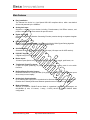
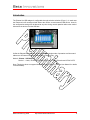
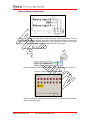
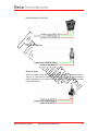
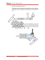
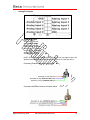
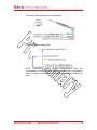
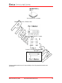
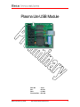
Plasma Lite USB Module DOC No. Rev. Date Firmware Rev. Beta Innovations (c) 2004 : 16511 : A8-100 : 6, 2004 : 600-100 http:\\www.betainnovations.com 1 Table of Contents Main Features..................................................................................................4 Introduction.....................................................................................................5 Plasma Configuration ....................................................................................6 Configuration Selection DIP Switches ............................................... 6 Configuration Options ........................................................................ 6 Plasma-Lite Pin-Out .......................................................................................8 Digital POV HAT Inputs...................................................................... 8 Connecting Digital POV HATS .................................................... 8 Mechanical Rotary Encoder Input...................................................... 9 Connecting Rotary Encoders....................................................... 9 Button Inputs .................................................................................... 10 Connecting Various Switches – All Modes................................ 10 SPST Toggle Switches (On-Off) ............................................... 10 SPDT Switches (On-On) ........................................................... 10 Rocker Switches (On-Off-On).................................................... 11 Push Button Switches................................................................ 11 Rotary Switches......................................................................... 11 Mechanical / Optical Rotary Encoders ...................................... 12 Multi-Position Rotary Switches .................................................. 12 Analog Port Inputs............................................................................ 13 Connecting Potentiometers to Analog Inputs ............................ 13 Connecting Hall Effect Sensors to Analog Inputs...................... 13 Connecting Linear Transducers to Analog Inputs ..................... 14 Connecting Analog Joystick Pots .............................................. 14 Axis Synchronization........................................................................ 15 Connecting Axis Synchronization Switch .................................. 15 Hardware Specifications .............................................................................16 Mechanical Specifications ..........................................................................17 Bill Of Materials.............................................................................................18 Beta Innovations (c) 2004 http:\\www.betainnovations.com 2 Plasma Lite USB Module Beta Innovations (c) 2004 http:\\www.betainnovations.com 3 Main Features Easy installation The Plasma Lite device is a Low Speed USB HID compliant device, which uses default drivers and powered by the USB Bus. Analog Axis Input Supports a variety of input devices including, Potentiometers, Hall Effect sensors, and pressure transducers or force sensors for precise control. Digital Axis Input Supports up to 4 ACE (Absolute Contacting Encoder) rotaries through a separate daughter board. Filtering Algorithm Features a proprietary selectable 2 level Recursive Moving Delta Sigma filtering algorithm virtually eliminating noise, spike and jitter for stable output. Axis Resolutions Selectable analog axis resolution from 32 to 256 steps (128 steps max for ACE rotaries). POV HAT Support 2 Digital 8-way POV HAT inputs. Button Inputs 16 button inputs (Active Low) compatible with any kind of switch: toggle, push button, etc. Trim Switch / Rapid Fire Inputs 2 rapid fire inputs producing 10 pulses per second which can be used for trim switch functions. Buffered Rotary Encoder Support Dedicated channel for a rotary encoder (2 bit gray code). Buffered outputs prevent lost inputs when rotary is turned rapidly. Analog Axis Synchronization Up to 4 analog axis inputs can be synchronized to eliminate asymmetric thrust on multi-lever throttles due to linearity differences between potentiometers or any other input devices. Mode of Operation Adheres to Plasma’s SINGLE device Mode A operational parameters. Enumerates as 8X16B1R2H (8 axis, 16 buttons, 1 rotary, 2 HATs) device in Plasma SINGLE Mode configuration. Beta Innovations (c) 2004 http:\\www.betainnovations.com 4 Introduction The Plasma Lite USB adapter is configurable through selection switches (Figure 1). In each case the Plasma unit will reconfigure itself without the need to re-enumerate as USB device. As such, the configuration settings can be altered at any time during normal operation without the need to disconnect the device form the USB bus. Figure 1 Unlike the Plasma V2 module this device operates in a single mode of operation at all times and adheres to all Plasma functionality with respect to Mode A only. Mode A: Plasma - USB Adaptor Device 1 – 8 axis, 14 buttons, 2 Rapid Fire inputs, 1 Rotary Encoder and 2 POV HATS Note: This device does not support Modes B through C (Refer to Plasma User Manual for details on these Modes). Beta Innovations (c) 2004 http:\\www.betainnovations.com 5 Plasma Configuration The Plasma Lite module has several user adjustable DIP switches that allow the configuration of various onboard systems and device features. Configuration Selection DIP Switches Configuration selection DIP switches (Figure 2) can be used to activate additional operational features. Figure 2 DIP Switch S1: Switch 1 – Level 1 Analog Axis Filter Switch 2 – Level 2 Analog Axis Filter, Level 1 must be active Switch 3 – ACE Rotaries on X & Y Axis Switch 4 – ACE Rotaries on Z & Rx Axis Switch 5 – Axis Synchronization Switch 6 – 2 / 4 Axis Synchronization Switch 7 – Analog Axis Resolution LSB (Least Significant Bit) Switch 8 – Analog Axis Resolution MSB (Most Significant Bit) Configuration Options Level 1 Analog Axis Filter: is adequate for eliminating a substantial amount of jitter (noise), but has poor attenuation properties on spikes and extreme cases of line noise. This level of filtering has no noticeable effect on input sensitivity. Level 2 Analog Axis Filter: virtually eliminates most forms of spiking and line noise but may adversely affect input sensitivity. As a result, level 2 filtering should only be activated when absolutely necessary. Level 2 filtering will only work in conjunction with level 1 filtering therefore level 1 filtering must be turned ON. NOTE: ACE rotaries are not filtered due to their digital nature. To activate filtering, toggle ON the appropriate dip switch on S1. A substantial improvement was made over the filtering algorithm used in the previous version of Plasma with the addition of a user selectable level of filtering for jitter (noise) and spikes, the two most common drawbacks associated with potentiometers. Beta Innovations (c) 2004 http:\\www.betainnovations.com 6 In certain instances where raw input data is preferred, reducing the axis resolution can be sufficient to effectively eliminate these undesired elements. ACE Rotaries – If you have connected an ACE add-on board to your Plasma Lite unit you can activate the add-on module by toggling ON switch 3 and/or 4 on S1. ACE Rotaries on X & Y Axis – Toggling ON switch 3 on S1, ACE rotary digital data will be used for the X & Y axis inputs. The X and Y analog axis ports on the device will no longer be active and ACE digital data will be used instead. ACE Rotaries on Z & Rx Axis – Toggling ON switch 4 on S1, ACE rotary digital data will be used for the Z & Rx axis inputs. The Z and Rx analog axis ports on the device will no longer be active and ACE digital data will be used instead. NOTE: ACE axis data cannot be diverted to any other analog axis ports and are ideally suited for throttle levers. Axis Synchronization – The device is equipped with an analog axis synchronization feature. Switch 5 will activate this feature and can be toggled ON/OFF through a momentary push button switch connected to JP5. 2 / 4 Axis Synchronization – If switch 6 is set to OFF, only the X & Y axis on the device will be synchronized. When switch 6 is set to ON, X, Y, Z and Rx axis will be synchronized. Synchronization can be toggled ON/OFF through a momentary push button switch connected to JP5. Analog Axis Resolution – All analog axes have 4 pre-settable axis resolutions. One setting affects all analog inputs on the Plasma unit. The step number represents the maximum number of possible discrete positions on the output. DIP Switch S1: Switch 7 – Analog Axis Resolution LSB Switch 8 – Analog Axis Resolution MSB 32 step resolution: Switch 7 – off Switch 8 – off 64 step resolution: Switch 7 – on Switch 8 – off 128 step resolution: Switch 7 – off Switch 8 – on 256 step resolution: Switch 7 – on Switch 8 – on The higher the step size the more likely the output will suffer from the effects of jitter due to the LSB uncertainty in the ADC conversion process. As such, there is a trade off between resolution and stability of the output signal. The output signal stability is also heavily dependent on the use of high quality input devices (i.e Hall Sensors, Potentiometers, etc.). Therefore, activation of the digital filter is recommended if a clean stable signal is required at the output while maintaining a high degree of step size and resolution. Beta Innovations (c) 2004 http:\\www.betainnovations.com 7 Plasma-Lite Pin-Out Digital POV HAT Inputs Connecting Digital POV HATS HAT input 1: POV SWITCH UP HAT input 2: POV SWITCH RIGHT HAT input 3: POV SWITCH DOWN HAT input 4: POV SWITCH LEFT The POV HAT switch common pin must be connected to one of the ground pins. All other HAT switch pins must be connected to the appropriate input pins as describe above. Beta Innovations (c) 2004 http:\\www.betainnovations.com 8 Mechanical Rotary Encoder Input The mechanical rotary encoder inputs convert 2-bit gray code type encoders only that have the same number of detents and pulses. These inputs are buffered to prevent lost inputs with a maximum output rate limited to 12 PPS (Pulses Per Second). The pulse output is comprised of a 40 ms ON pulse followed by a 40 ms OFF pulse. Connecting Rotary Encoders Rotary outputs are located on button inputs 17 & 18 illustrated below (Figure 3). Figure 3 – Rotary output MODES A & B NOTE: Any software reading device inputs less than 25 Hz (25 times per second) will invariably drop inputs. Beta Innovations (c) 2004 http:\\www.betainnovations.com 9 Button Inputs Unlike the standard button inputs, Rapid Fire Inputs send a pulse stream instead of a continuous ON signal. The pulse rate has been preset to 10 PPS (Pulses Per Second). Connecting Various Switches – All Modes The Plasma module does not use a scan matrix type of input layout. As such, diodes are not required and will not suffer from phantom signals when activating several switch inputs at the same time. SPST Toggle Switches (On-Off) SPDT Switches (On-On) Beta Innovations (c) 2004 http:\\www.betainnovations.com 10 Rocker Switches (On-Off-On) Push Button Switches Rotary Switches These are special rotary type switches that do not require a decoder circuit in order to be used with the Plasma Lite button inputs. Typical rotary encoders require a decoder circuit in order to convert the output signals into a form usable by this USB module. Beta Innovations (c) 2004 http:\\www.betainnovations.com 11 Mechanical / Optical Rotary Encoders These types of rotary encoders require a decoder circuit in order to convert the output signals into a form usable by this USB module. Rotary output signals can be 2-bit gray code or 2-bit quadrature code depending on the decoder circuit used. Multi-Position Rotary Switches Multi-Position Rotary Switches come in many configurations, but the most important thing to note is that they all share one or several common pins. These common pins must to be connected to any one of the common GND pins found on the Plasma unit. All other pins can be connected to any one of the inputs as required. Beta Innovations (c) 2004 http:\\www.betainnovations.com 12 Analog Port Inputs Analog Axis Inputs Analog Input 1: X-Axis Analog Input 2: Y-Axis Analog Input 3: Z-Axis Analog Input 4: X-Rotation Analog Input 5: Y-Rotation Analog Input 6: Z-Rotation Analog Input 7: Slider 1 Analog Input 8: Slider 2 NOTE: Some operating system’s default USB drivers may not support 8 axis. MS Windows 98 (USB Upgrade) / ME / 2000 / XP support up to 8 axis per device. Connecting Potentiometers to Analog Inputs Connecting Hall Effect Sensors to Analog Inputs Beta Innovations (c) 2004 http:\\www.betainnovations.com 13 Connecting Linear Transducers to Analog Inputs Connecting Analog Joystick Pots NOTE: Conventional analog Joystick potentiometers have one unconnected pin on axis pots. It is imperative that this pin be grounded in order to properly function when connected to the Plasma analog port inputs. Beta Innovations (c) 2004 http:\\www.betainnovations.com 14 Axis Synchronization With the inherent linearity errors of potentiometers, analog input values can differ by as much as 20% under worst case conditions. This can cause undesired effects when precision between multiple analog input is required on 2 or 4 engine throttle quadrants. Although more expensive solutions exist (i.e. ACE’s, Hall Sensors, etc.) which do not suffer from these linearity differences, a simple solution is employed on select analog ports by averaging the inputs and eliminating these linear variations. This synchronization can be quickly activated when needed by pressing a momentary push button connected to JP5. Connecting Axis Synchronization Switch NOTE: Although axis synchronization can be used in conjunction with ACE rotaries, it should be noted that it is not required due to their high degree of linearity. Beta Innovations (c) 2004 http:\\www.betainnovations.com 15 Hardware Specifications The firmware runs at 40 ms iteration rate in operational Mode A. As such, any custom interface software should poll this device at least every 40 ms to prevent lost inputs. The 40 ms interval time is more than adequate to debounce switch contacts if any are used as inputs. Note that all inputs are active low, which means you must ground an input in order to register a high “ON” signal at the output. Most operating systems will detect and load the appropriate HID driver for your device and do not require that a custom device driver be installed. On some operating systems, these default drivers may not support all features of the Plasma Lite module. Maximum power consumption is 500mW (100mA) and is powered by the USB bus. You do not need to use an external power supply for this device, even when connecting (and powering) several rotary decoder modules from the onboard power pins specifically added for this purpose. NOTE: DO NOT CONNECT any of the Plasma Lite Vcc pins to external power supplies or voltage sources. Although common grounds can be safely connected to external grounds, it is not recommended and should be avoid whenever possible. Doing so may adversely affect performance, possibly causing strange or erratic behavior under certain conditions. Beta Innovations (c) 2004 http:\\www.betainnovations.com 16 Mechanical Specifications Beta Innovations (c) 2004 http:\\www.betainnovations.com 17 Bill Of Materials C1 C2 C3 C4 C5 C6 C7 J1 JP1 JP2 JP3 JP4 JP5 JP6 JP8 R1 R4 R5 S1 U1 U2 U3 U4 Y1 0.1µF, 20%, 50VDC Ceramic 0.1µF, 20%, 50VDC Ceramic 0.1µF, 20%, 50VDC Ceramic 0.1µF, 20%, 50VDC Ceramic 0.1µF, 20%, 50VDC Ceramic 0.1µF, 20%, 50VDC Ceramic 0.1µF, 20%, 50VDC Ceramic USB Type 'B' Connector Header, 10-Pin .100, Dual row Header, 10-Pin .100, Dual row Header, 10-Pin .100, Dual row Header, 20-Pin .100, Dual row Header, 2-Pin .100, Straight Connector receptacle, 3-Pin .100 Header, 2-Pin .100, Right Angle EXB-F6E822G 8.2K, 10%, 1/4W, 5 Resistor pack with common pin 10K, 10%, 1/4W 1.5K, 1% Metal Film, 1/4W AMP 435640-5 DIP Switch, 8 toggle switches MC74HC4051AN 8-Channel Analog Multiplexer/Demultiplexer MC74HC4051AN 8-Channel Analog Multiplexer/Demultiplexer MC74HC4051AN 8-Channel Analog Multiplexer/Demultiplexer PIC16C765-I/L EPROM-Based 8-Bit CMOS Microcontroller with A/D Converter 44 pin PLCC socket for U9 6MHz Ceramic Resonator with integrated 22 pf capacitors IMPORTANT: Care must be taken if substituting the analog multiplexer IC's (MC74HC4051AN) in order to minimize analog signal degradation and performance. If the MC74HC4051AN must be substituted, it is imperative that ICs with the lowest “on resistance” are selected. Clearly identify all PIN 1 positions prior to component placement. Particular attention must be paid to the orientation of the following critical components: PIC16C765-I/L Microcontroller PLCC Socket Pin 1 Location Beta Innovations (c) 2004 http:\\www.betainnovations.com 18 PIC16C765-I/L Pin 1 Location EXB-F6E822G - 8.2K, 5 Resistor Pack Resistor Network Pack Pin 1 Location Common Terminal Resistor Network R1 Pin 1 Marker Visit www.betainnovations.com for the availability of kits, fully assembled modules and accessories. Beta Innovations (c) 2004 http:\\www.betainnovations.com 19