1
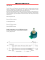
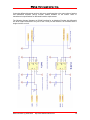
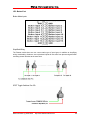
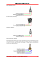
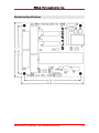
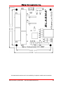
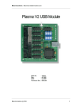
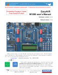
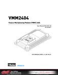
Beta Innovations Inc.
Plasma-Lite V2 USB Module
Beta Innovations (c) 2005-2008
http://www.betainnovations.com
Beta Innovations Inc.
Product ID.
Board Rev.
Date
Firmware Rev.
Beta Innovations (c) 2005-2008
: 910
: 3.00
: April 30, 2008
: 2.82
http://www.betainnovations.com
2
Beta Innovations Inc.
Table of Contents
Plasma-Lite V2 USB Module ...................................................................5
Main Features ..........................................................................................6
Introduction ..............................................................................................7
Flash Loader Mode : JP7.........................................................................8
RESET Jumper JP7 ...................................................................................................................8
Plasma-Lite V2 Button Structure .............................................................9
Buttons Structure .......................................................................................................................9
Plasma-Lite V2 Pin-Out .........................................................................10
JP1: HAT Port ..........................................................................................................................10
POV Mode .........................................................................................................................10
Digital Mode.......................................................................................................................11
RXC: Shifter Display Mode................................................................................................11
RXC: 12-Bit DACs Mode ...................................................................................................12
Incremental Encoder Mode ...............................................................................................13
LBG10-DG Mode ...............................................................................................................14
NITRO Mode......................................................................................................................14
JP2: ACE Port ..........................................................................................................................15
ACE-4X expansion card ....................................................................................................15
GT-X64 expansion card.....................................................................................................15
Absolute MAB25 Encoders................................................................................................15
Absolute SSI Encoders......................................................................................................16
Character LCD 20 x 4........................................................................................................19
JP3: Button Port .......................................................................................................................20
Button Mode Inputs ...........................................................................................................20
Simplified Wiring ................................................................................................................20
SPST Toggle Switches (On-Off)........................................................................................20
SPDT Switches (On-On) ...................................................................................................21
Rocker Switches (On-Off-On)............................................................................................21
Beta Innovations (c) 2005-2008
http://www.betainnovations.com
3
Beta Innovations Inc.
Push Button Switches........................................................................................................21
Multi-Position Rotary Switches ..........................................................................................21
Rotary Mode Inputs ...........................................................................................................22
JP4: Analog Port ......................................................................................................................24
Simplified Wiring ................................................................................................................24
Connecting Hall-Effect Sensors to Analog Inputs .............................................................25
Connecting Linear Transducers to Analog Inputs .............................................................25
Connecting Analog Joystick Pots ......................................................................................25
Hardware Specifications ........................................................................26
Device Status LEDs .................................................................................................................26
Mechanical Specifications .....................................................................27
Beta Innovations (c) 2005-2008
http://www.betainnovations.com
4
Beta Innovations Inc.
Plasma-Lite V2 USB Module
Beta Innovations (c) 2005-2008
http://www.betainnovations.com
5
Beta Innovations Inc.
Main Features
Easy installation
The Plasma-Lite V2 device is a Full Speed USB HID compliant device, which employs default
drivers supplied by most OS and powered by the USB Bus.
Analog Axis Input
Supports a variety of input devices including, Potentiometers, Hall-Effect sensors, and
pressure transducers or force sensors for precise control.
Expansion Port
Supports multiple expansion modules such as the ACE-4X 32 button input module, 13-Bit
Absolute Encoders or Character LCDs.
Filtering Algorithm
Features a proprietary user adjustable 2 level Recursive Moving Delta Sigma filtering
algorithm virtually eliminating noise, spike and jitter for stable output.
Hardware Calibration
All axis channel calibration data is stored onboard eliminating the need for calibration in
Windows. Additionally, axis channels can be tweaked for optimal performance as needed by
setting trim zones.
Axis Resolutions
Up to 12-bits (4095 steps) axis resolution on analog channels and up to 16-bits (65535 steps)
on digital channels.
POV HAT Support
2 Digital 8-way POV HAT inputs.
Button Inputs
Up to 24 button inputs (Active Low) compatible with any kind of switch: toggle, push button,
etc. Each input individually configurable for various modes of operation.
Rotary Encoders
Up to 8 rotary encoders supported. Decoding options include Gray Code 1X, 2X, 4X.
Incremental Encoder
Supports a single high-resolution incremental encoder for up to 4000 PPR (1000 CPR) and
16-bit range (0 to 65535).
Absolute Encoders
Up to 6 absolute encoders (13-bits) supported.
Software Configurable Operation
Device features can be customized through a simple to use configuration utility.
Flash Loader Mode
Incorporates a Flash Loader for easy firmware update via USB.
Beta Innovations (c) 2005-2008
http://www.betainnovations.com
6
Beta Innovations Inc.
Introduction
The Plasma-Lite V2 USB adapter is the next generation input device now featuring 12-bit
resolution on analog channels, 16-bit resolution on digital channels and software configurable.
Through various parameters, many aspects of the device can be controlled, adjusted, activated or
deactivated to meet individual needs. In each case the Plasma unit will reconfigure itself without
the need to re-enumerate. As such, the configuration settings can be altered at any time during
normal operation without the need to disconnect the device from the USB bus.
Driver installation is automatic and most OS will install the required drivers without any user
intervention. Note: Reset jumper JP7 should be removed prior to plugging the device into a USB port.
Beta Innovations (c) 2005-2008
http://www.betainnovations.com
7
Beta Innovations Inc.
Flash Loader Mode : JP7
The Plasma-Lite V2 USB adapter consists of 2 devices in 1. In Flash Loader mode, the module
enumerates as a non-joystick device used solely for updating the core firmware via USB. In Device
mode the Plasma unit operates as a standard DirectX compatible joystick device.
RESET Jumper JP7
RESET jumper JP7 can be used to restart the device in Flash Loader mode. It should remain
open (disable) for normal device operation. The device can be set in Flash Loader mode when
needed in order to update the core Plasma-Lite firmware. The jumper must be removed after
successful firmware update prior to rebooting the device. See the Device Manager utility user
manual for details on firmware update procedures.
Beta Innovations (c) 2005-2008
http://www.betainnovations.com
8
Beta Innovations Inc.
Plasma-Lite V2 Button Structure
Buttons Structure
1
9
17
2
10
18
3
11
19
4
12
20
5
13
21
6
14
22
7
15
23
8
16
24
ACE-4X
25
33
41
49
26
34
42
50
27
35
43
51
28
36
44
52
29
37
45
53
30
38
46
54
31
39
47
55
32
40
48
56
GT-X64
25
33
41
49
57
65
73
26
34
42
50
58
66
74
27
35
43
51
59
67
75
28
36
44
52
60
68
76
29
37
45
53
61
69
77
30
38
46
54
62
70
78
31
39
47
55
63
71
79
32
40
48
56
64
72
88
Digital Channel
Buttons
HAT Digital Mode
The structure above lists the button order as seen by applications running on systems supporting
USB HID compliant devices. Note that not all OS drivers are capable of reading all inputs. Legacy
Windows drivers will only support the first 32 buttons including the Game Controllers applet found
in the Control Panel. However, DirectX drivers and any software that uses DirectX Direct Input
can support up to 128 buttons per device. There are no limits for Beta Innovations custom drivers,
which as of this writing support up to 256 inputs per device.
When digital inputs are configured as rotary encoders, decoded outputs will be in pairs as
illustrated below.
Digital Channel
Rotary Mode
Rotary 1
1
2
9
10
Rotary 5
Rotary 2
3
4
11
12
Rotary 6
Rotary 3
5
6
13
14
Rotary 7
Rotary 4
7
8
15
16
Rotary 8
The current firmware revision only supports rotary encoders on digital channels. Support for
rotary encoders on other channels may be added in a future firmware update.
Beta Innovations (c) 2005-2008
http://www.betainnovations.com
9
Beta Innovations Inc.
Plasma-Lite V2 Pin-Out
JP1: HAT Port
POV Mode
HAT input 1: POV SWITCH UP
HAT input 2: POV SWITCH RIGHT
HAT input 3: POV SWITCH DOWN
HAT input 4: POV SWITCH LEFT
The POV HAT switch common pin must be connected to one of the ground pins. All other HAT
switch pins must be connected to the appropriate input pins as describe above.
Beta Innovations (c) 2005-2008
http://www.betainnovations.com
10
Beta Innovations Inc.
Digital Mode
When the POV HAT port is configured in Digital Mode, standard switches can be connected for 8
additional button inputs to the standard compliment of 16 for a total of 24 button inputs. Refer to
the Button Inputs section for details on connecting switches to POV HAT port inputs.
RXC: Shifter Display Mode
When HAT channel 2 is set to RXC : Shifter Display mode, pins 7 through 10 will be configured
as BCD (Binary Coded Decimal) output pins. Shifter positions supported are from 1 to 9 with
Neutral being displayed as 0 and Reverse as blank output. These outputs can be used to drive a
7-segment display through any standard BCD-TO-SEVEN SEGMENT decoder driver chip as
illustrated bellow.
Beta Innovations (c) 2005-2008
http://www.betainnovations.com
11
Beta Innovations Inc.
The schematic above uses a Common Cathode display with a 7449 decoder IC. Alternately, a
7447 IC can be used with Common Anode displays.
RXC: 12-Bit DACs Mode
When HAT channel 1 is set to RXC: 12-Bit DACs mode, pins 3 through 6 will be configured as
SPI output pins to control up to 4 12-Bit DACs such as the MCP4922. The MCP4922 is a dual
DAC on a single IC package capable of Rail-to-Rail output and employs an SPI interface.
SPI Interface:
SCK – Clock
SDO – Data
CS1 – Chip Select 1
CS2 – Chip Select 2
DAC outputs can be connected to standard Air-Core driver circuit such as the AC305A/B and
AC360A/B/C circuits.
Beta Innovations (c) 2005-2008
http://www.betainnovations.com
12
Beta Innovations Inc.
Decoupling capacitors (0.1µF Ceramic) should be placed as close to the VCC pins of the DAC
ICs.
Incremental Encoder Mode
When the HAT channel 1 is set for Incremental Rotary Encoder mode, pins 3 through 6 will be
reconfigured as show above. Inputs on pins 5 and 6 are defaulted to digital inputs mode.
Incremental inputs will decode any standard quadrature encoded rotary for up to 4000 PPR
(Pulses Per Revolution) or 4000 discrete steps per revolution up to a maximum range from 0 to
65535 (16-bits).
Note: Manufacturer’s encoder documentation may specify output as PPR or CPR (Cycle Per
Revolution). To determine PPR, multiply CPRs by 4.
Typical incremental output pulses are illustrated below.
Beta Innovations (c) 2005-2008
http://www.betainnovations.com
13
Beta Innovations Inc.
Pulse output A leads B by 90 deg. Index Z pulse occurs once per revolution. Current firmware
does not support index pulses.
IMPORTANT: Only TTL output drivers (4.5V – 5.5V) can be directly connected to the Plasma-Lite
pins. Rotary encoder current consumption must not exceed 100mA. Rotary encoders with current
consumption exceeding 100mA will require their own power supply. Refer to manufacturer’s
specification sheets for details.
LBG10-DG Mode
When HAT channel 1 is set to LBG10-DG mode, pins 3 through 5 will be configured as SPI
output pins to control a single LED bar graph display.
SPI Interface:
SCLK – Serial Clock
SDO – Serial Data Out
CS – Chip Select
NC – No Contact
In addition to the above pins, the LBG10-DG must be connected to any one of the 5V pins not
shown. Refer to LBG10 user manual for details.
NITRO Mode
Refer NITRO user manual for details.
Beta Innovations (c) 2005-2008
http://www.betainnovations.com
14
Beta Innovations Inc.
JP2: ACE Port
The ACE Port on the Plasma-Lite module provides the means to expand current options and
features not supported by the standard ports. The expansion port was designed to provide
interconnectivity with external hardware using minimal support circuitry.
Note that as new firmware features are added, it may become necessary to make changes to the
layout of any support circuitry in order to maximize functionality and efficiency. Before updating
the device firmware, verify that the addition of new features do not conflict with previous ACE port
add-ons in use.
ACE-4X expansion card
Refer to ACE-4X user manual.
GT-X64 expansion card
Refer to GT-X64 user manual.
Absolute MAB25 Encoders
Current firmware supports up to 6 MAB25 series Absolute
Encoders connected to the ACE expansion port using
Synchronous Serial Interface 16-bit data words as illustrated in
the timing diagram bellow.
Beta Innovations (c) 2005-2008
http://www.betainnovations.com
15
Beta Innovations Inc.
MAB25 Pin out
UB – JP2 Pin 10, VCC
CS – JP2 CS 1 - 6 pins
CLK – JP2 Pin 8
DATA – JP2 Pin 6
GND – JP2 Pin 1, GND
PROG – NC
The maximum supported resolution is 12-bits per channel. Contact us for custom solutions
requiring higher resolutions. MAB25 absolute encoders employ non-contacting hall-sensor
technology. No additional support circuitry or power supply is required when connecting these
encoders to the ACE port.
Absolute SSI Encoders
Current firmware supports up to 6 Absolute Encoders such as the Heidenhain ROC-41X
connected to the ACE expansion port using 13-bit data words SSI (Serial Standard Interface) as
illustrated in the timing diagram bellow.
Beta Innovations (c) 2005-2008
http://www.betainnovations.com
16
Beta Innovations Inc.
The maximum supported resolution is 13-bits per channel. Contact us for custom solutions
requiring higher resolutions.
Serially interfaced absolute encoders employ either standard or proprietary communication
protocols. The current firmware supports standard serial interfaces, some of which require
minimal support circuitry ranging from a simple pull-up resistor to RS-485 transceivers for clock
and data lines on differential interfaces.
Open Collector: requires a pull-up resistor between the OUTPUT pin and Plasma-Lite Vcc.
Can be connected directly to Plasma’s inputs provided the outputs are TTL (4.5V-5.5V).
Refer to manufacturer’s specifications for value of pull-up resistor.
Pull-Up Resistor: can be connected directly to Plasma’s inputs provided the outputs are TTL
(4.5V-5.5V).
Line Driver Outputs: requires transceivers to convert differential signals to TTL for
compatibility with ACE port inputs pins.
Beta Innovations (c) 2005-2008
http://www.betainnovations.com
17
Beta Innovations Inc.
Connecting differential outputs can be a little more complicated due to the vast number of options
and differences between various encoder models available on the market. Refer to
manufacturer’s specifications for differential interface requirements.
The following diagram illustrates an RS-485 interface for an Absolute Encoder with differential
line driver output connected to any one of the 6 ACE port AE channels. All Encoders share a
single clock line on pin 6.
Beta Innovations (c) 2005-2008
http://www.betainnovations.com
18
Beta Innovations Inc.
Character LCD 20 x 4
When the ACE port is set to “Character LCD 20 x 4” mode, the port pins will be configured as
indicated above for controlling any HD44780 compatible character LCD under 4-bit control. Refer
to the Device Manager help file for details on configuring the ACE port for LCD support.
The ACE port can supply all the require current to drive a backlit LCD. The VCC pin 10 on the
ACE port supplies power to the LCD.
IMPORTANT: YOU MUST USE a self powered USB HUB or the device will fail enumeration.
Standard USB ports can only deliver up to 100mA per port.
Beta Innovations (c) 2005-2008
http://www.betainnovations.com
19
Beta Innovations Inc.
JP3: Button Port
Button Mode Inputs
Simplified Wiring
The Plasma module does not use a scan matrix type of input layout. In addition to simplifying
wiring considerably, diodes are not required and inputs will not suffer from phantom signals when
activating several switches at the same time.
SPST Toggle Switches (On-Off)
Beta Innovations (c) 2005-2008
http://www.betainnovations.com
20
Beta Innovations Inc.
SPDT Switches (On-On)
Rocker Switches (On-Off-On)
Push Button Switches
Multi-Position Rotary Switches
Multi-Position Rotary Switches come in many configurations, but the most important thing to note
is that they all share one or several common pins. These common pins must to be connected to
any one of the common GND pins found on the Plasma unit. All other pins can be connected to
any one of the inputs as required.
Beta Innovations (c) 2005-2008
http://www.betainnovations.com
21
Beta Innovations Inc.
Rotary Mode Inputs
When pairs of digital Inputs are configured in Rotary Mode, standard rotaries can be connected to
the inputs for decoding without the need for external decoding circuitry. A maximum of 8 rotaries
can be connected to input pairs.
Note that not all inputs need to be configured for rotary support. The example below shows input
pairs 1 – 2 & 15 –16 configured for rotary support. All other inputs are in standard digital mode.
Current firmware revision supports 3 types of phase shifted encoding as illustrated below.
Gray Code 1X
Gray Code 2X
Gray Code 4X
Decoding method depends largely on how the physical detents are implemented on the rotary
with respect to output pulses. Rotary encoders that do not have any detents “D” can employ any
of the above methods with up to 4X multiplier on output pulses.
Gray code 1X: provides a 1:1 decoding of phased pulses. Each input pulse results in a single
output pulse.
Beta Innovations (c) 2005-2008
http://www.betainnovations.com
22
Beta Innovations Inc.
Gray Code 2X: provides a 1:2 decoding of phased pulses. Each input pulse results in 2 output
pulses.
Gray Code 4X: provides a 1:4 decoding of phased pulses. Each inputs pulse results in 4 output
pulses.
Typical rotaries consist of 3 pins. Pin “A” & “B” are the encoded outputs and one common middle
pin “C”. Refer to manufacturer’s specifications for exact pin out.
Beta Innovations (c) 2005-2008
http://www.betainnovations.com
23
Beta Innovations Inc.
JP4: Analog Port
Default Analog Axis Inputs
Analog Input 1: X-Axis
Analog Input 2: Y-Axis
Analog Input 3: Z-Axis
Analog Input 4: X-Rotation
Analog Input 5: Y-Rotation
Analog Input 6: Z-Rotation
Analog Input 7: Slider 1
Analog Input 8: Slider 2
NOTE: Some operating system’s default USB drivers may not support 8 axes. MS Windows 98
(USB Upgrade) / ME / 2000 / XP support up to 8 axis per device.
Simplified Wiring
Connecting Potentiometers to Analog Inputs
Beta Innovations (c) 2005-2008
http://www.betainnovations.com
24
Beta Innovations Inc.
Connecting Hall-Effect Sensors to Analog Inputs
A low pass filter may be required on the output of some Hall-Effect Sensors due to mismatch
conditions with the input impedance of the ADC’s sampling circuitry and/or noise from the HallEffect Sensor amplifier circuit.
Component values are dependant on the frequency of the output signal noise.
Connecting Linear Transducers to Analog Inputs
Connecting Analog Joystick Pots
NOTE: Conventional analog
Joystick potentiometers have
one unconnected pin on axis
pots. It is imperative that this pin
be grounded in order to properly
function when connected to the
Plasma analog port inputs.
Beta Innovations (c) 2005-2008
http://www.betainnovations.com
25
Beta Innovations Inc.
Hardware Specifications
All inputs on the Plasma-Lite V2 are active low, which means you must ground an input in order
to register a high “ON” signal at the output.
Most operating systems will detect and load the appropriate HID driver for your device and do not
require that a custom device driver be installed. These default drivers may not support all features
of the Plasma-Lite V2 module on some operating systems.
Maximum power consumption is 2.5W (500mA) and is powered by the USB bus. You do not need
to use an external power supply for this device, even when connecting (and powering) several
expansion modules from the onboard power pins specifically added for this purpose.
IMPORTANT: YOU MUST USE a self powered USB HUB or the module will fail
enumeration. Standard USB ports can only deliver up to 100mA per port.
Potentiometer values are not critical for the proper operation of analog inputs, but values should
not be less than 5K Ohm and not greater than 1Meg Ohm for optimal operation. Keep the wiring
tidy and as short as possible. Do not twist pot wires. Use untwisted shielded cabling or a flat
ribbon cable.
In order to avoid potential damage to the analog inputs, pots should be connected to the port with
the power turned off by disconnecting the unit from the USB bus.
IMPORTANT: DO NOT CONNECT any of the Plasma-Lite V2 Vcc pins to external power
supplies or voltage sources. Although common grounds can be safely connected to external
grounds, it is not recommended and should be avoided whenever possible. Doing so may
adversely affect performance, possibly causing strange or erratic behavior under certain
conditions.
DO NOT PLUG any expansion modules into the expansion port while the unit is plugged
into a USB port. Disconnect the device from the USB bus prior to installing an expansion
module. See expansion module user manual for details.
Device Status LEDs
D1
D2
Description
( Off
( Off
Device not powered or not enumerated.
( On
( On
Device enumerated in Flash Loader mode.
( On
( Off
Device enumerated in standard Device mode.
(( Flashing
(( Flashing
Device in Suspend state.
( On
(( Flashing
Transmitting data to USB host (Flash Loader Mode).
(( Flashing
( On
Receiving data from USB host (Flash Loader Mode).
( On
(( Flashing
Transmitting data to USB host (Device Mode).
(( Flashing
(( Flashing
Receiving data from USB host (Device Mode).
Beta Innovations (c) 2005-2008
http://www.betainnovations.com
26
Beta Innovations Inc.
Mechanical Specifications
Beta Innovations (c) 2005-2008
http://www.betainnovations.com
27
Beta Innovations Inc.
Visit www.betainnovations.com for the availability of expansion modules and accessories.
Beta Innovations (c) 2005-2008
http://www.betainnovations.com
28