1
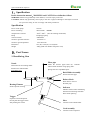
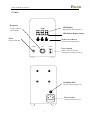
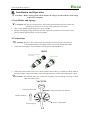
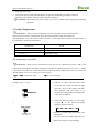
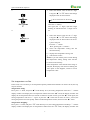
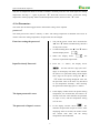
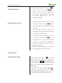
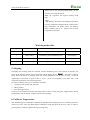
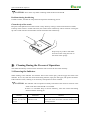
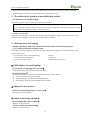
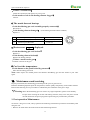
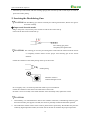
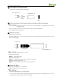
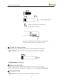
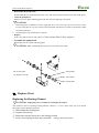
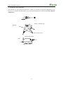
QUICK 201B Desoldering Tool
Instruction Manual
Thank you for purchasing this desoldering tool. Please read manual carefully before using. Store this
manual in a safe, easily accessible place for future reference.
QUICK 201B Manual Operation
Ⅰ、Specification
In this instruction manual,WARNING and CAUTION are defined as follows
WARNING: Misuse may potentially cause death of, or serious injury to the user.
CAUTION: Misuse may potentially cause injury to the user or physical damage to the objects involved.
For your own safety ,be sure to comply with these precautions.
Specification
Power of the pump
Power of heating
Temperature of nozzle
Pump
Vacuum suction
Nozzle to ground resistance
Nozzle to ground potential
Dimension
Weight
12V/2A
90W/36VAC 400KHz
200℃~450℃ (See the working mode table)
Diaphragm pump
600mmHG
Less than 2Ω
Less than 2mV
105 (W)×250 (D)×165 (H)mm
4.8Kg (With iron holder and power cord)
Ⅱ、Part Names
1. Desoldering Gun
Filter pipe
Nozzle
Inside the ceramic paper filter (S). Contains
melted solder and flux using spring filter .
Spring filter are expendable parts.
Transmits heat for melting solder.
Entrance for melted solder.
Expendable part.
Back Holder Assembly
Secures the filter pipe.
Release Knob
Push down to remove
the filter pipe.
Heating Element
Indicator
Inside requires cleaning.
Indicates when nozzle and heating
element need cleaning and when
filters need replacing.
Trigger
Squeeze to start absorption.
Do not pull the trigger before
●主机
fully heating the nozzle.
Hose
Connects to the outside filter
Cord Assembly
Connects to the receptacle
1
QUICK 201B Manual Operation
2. Unite
Receptacle
LED Display
Connect with the
cord assembly.
Display the setup temperature
LED Heater Display Lamp
Tie-in
TEMP Control Button
Set and control temperature
Connect with filter.
VACUUM
IRON
POWER
Power Switch
When turned to ON, the
heating element starts to heat up.
Grounding Hole
Connect with grounding wire
Power Socket
Connect with Power cord
2
QUICK 201B Manual Operation
Ⅲ、Installation and Operation
!
CAUTION : Before setting, please check whether the voltage accords with the rated voltage
on the unit’s nameplate.
1. Iron Holder and Sponge
!
CAUTION: The sponge is compressed. It will swell when moistened with water. Water and
squeeze it dry. Failure to do so may result in damage to the nozzle.
1. Take out the desoldering gun and put it in the iron holder.
2. Dampen the cleaning sponge with water and then squeeze it dry, Be sure to remove the round
portion of the sponge and place it in the iron holder.
2. Connections
!
CAUTION: Be sure to turn off the power switch before connecting or disconnecting the
cord assembly and the power plug. Failure to de so may damage the P.W.B.
1. Connect the metal plug of cord assembly to the receptacle (marked “IRON”) .
IRON
Align the grooves and pins and
push stranght in
Turn clockwise firmly
2. Connect the external filter to the tie-in’s hose (marked “VACUUM”) in accordance with the mark on
!the external filter, need to insert fully, and connect the other side of filter to desoldering gun’s hose.
CAUTION: The external filter have connection orientation and connecting according to mark,
otherwise affect suction.
VACUUM
Connect to main unit
Fully insert filter into the hose
Airflow direction
Filter is expendable.
Connect to gun.
3
QUICK 201B Manual Operation
3. Plug the power cord.
4. Turn on the power switch and LED display is light, the desoldering gun begins to heat up.
!The heater lamp flickers when the temperature has stabilized.
CAUTION: After turning the power switch to ON, wait 3 minutes before beginning desoldering
operations.
3. Set the Temperature
!
CAUTION: Always set the temperature to as low as possible for the work being done.
The unit have two kinds of temperature setup: Normal temperature setup and instant one.
The temperature can be set between 200℃ and 480℃ with temperature control knob. Please refer to
the chart below, and set the temperature.
Temperature
P.W.B.
280-350 ℃
Single-sided P.W.B.
320-400 ℃
Through-hole P.W.B.
350-450 ℃
Multi-layer P.W.B.
Set temperature normally
!
CAUTION:
Make sure the temperature of the unit can be adjusted (password is OK or the
password is initial).While setting the temperature normally, the heating element is off. If the “*” button
is pressed for less than one second, the present temperature setting will be shown for two seconds and
then the display will return to showing the nozzle temperature.
“▲”,“▼”: Choose the value.
“*”:Choose the digit.
Example: 400℃ to 350℃
1.
1. Push the “*” button and the hold it down
for at least one second. The left-most digit
(the 100’s digit ) in the display will flash.
This indicates that the station is in
temperature setting mode and that the 100’
s digit can be adjusted.
2.
2.
Select the desired value for 100’s digit.
Using the “▲”or“▼”button will change
displayed value as follows.
…
2
3
4…
Press the “*” button when the desired value
is displayed.
This will cause the middle digit (the 10’s
digit) in the display to begin flashing.
4
QUICK 201B Manual Operation
3. Select the desired value for the 10’s digit.
Using the “▲”or“▼”button will change
displayed value as shown below.
3.
12t3t4t5t6t7t8t9t0
Press the “*” button.
The right (the 1’s digit) will then begin
flashing to indicate that the 1’s digit can be
set.
4.
4. Select the desired value for the 1’s digit.
Using the “▲”or“▼”button will change
displayed value as shown above for the 10’
s place selection.
Press the “*” button.
Here, pressing the “*” button…
a) enters the temperature setting into the
internal memory.
b) displays the temperature setting, and
c) starts heater control.
Note: If you turn off the power switch during
the temperature setting, setting value will not
be stored in the memory.
If the temperature value outside of this range is
selected, the display will return to flashing the
100’s place. If this happens, reenter a correct
temperature value.
Set temperature on-line
In the work, if it is necessary to set temperature quickly and the heat elements can not be cut off, the way
may be selected.
Temperature rising:
Don’t press “*” knob, and press“▲”knob directly. If so, the setting temperature will raise 1℃ and the
display window will display the set temperature. When loosen the “▲”knob, the display window will
display the set temperature about 2 seconds. If within 2 seconds of time, press the “▲”knob again, the
setting temperature will raise 1℃ again. If press the “▲”knob and not loose at least 1 second, the
setting temperature will rise rapidly. Till the needed temperature reaches, then loose the “▲”knob.
Temperature dropping:
Don’t press “*” knob, and press“▼”knob directly. If so, the setting temperature will drop 1℃ and the
display window will display the set temperature. When loose the“▼”knob, the display window will
5
QUICK 201B Manual Operation
relay the set temperature about 2 seconds. If within 2 seconds, press the“▼”knob again, the setting
temperature will drop 1℃ again. If press the“▼”knob and not loose at least 1 second, the setting
temperature will drop rapidly. Till the needed temperature reaches, then loose the“▼”knob.
4. Set Parameters
The station has the following parameters. Parameters setting can be adjusted.
password
The initial password in station’s memory is “000”. The setting temperature is admitted in this state. If
need to restrict the setting temperature, the password must be changed.
Enter into setting the password
1. Turn off the power switch. Press and hold the
“▲”and“▼ buttons simultaneously, then turn
on the power switch.
2. Continue holding down the “▲”and“▼”button
until the display shows
3. When the display shows
.
,the
station is in parameter-input mode.
Input Previously Password
4. Press the “*” button, the display shows
, and the left-most digit (the 100’s
digit) in the display will flash. This indicates
the station is in password setting mode and the
100’s digit can be adjusted. Using the “▲”or
“▼”button will change displayed value. Set
the password value in the same way described
in “set temperature normally”. After selecting
the password of three digit, press”*” button.
The input password is error
The password of input is correct
5. If the display window shows the present setting
temperature, two seconds later, the station is in
normal work state. This indicates the password
of input is error, and the temperature setting
can’t be done.
6. If the display window shows
, this
indicates the password of input is correct. After
displaying about 4 seconds, the station comes
into normal work state, and the setting
temperature will be admitted
6
QUICK 201B Manual Operation
7. When display window is showing
Input New Password
,
, It
press ”*” button, and shows
indicates the unit comes into inputting new
password state. Pressing“▲”or“▼”button
will
change
displayed
value.
See
“ set
temperature normally”
8. When three digits are selected, press”*” button,
Repeat the new password
the display window shows
again.
Now must input the new password. Repeat the
same steps.
9. If the password is the same as last time, the
changed password is OK. The new password is
stored into the internal memory.
10. If the password is not the same as last time, and
the display window shows
, the
station will ne- ed to rewrite new password.
(see the last 8-9 step). The changing of
password is finished until the lately two
passwords are identical.
*Note: The word of password is 0 to 9, ten words. If
not , the changed password is unsuccessful.
Working Mode
Working Mode Setting
If the display window shows
, press and
hold the “ ▲ ” and “ ▼ ”buttons simultaneously,
then the display shows
X . This indicates the unit
comes into working mode setting state, and pressing
“▲”or“▼”button will change displayed valve as
shown below:
0
1
0.
1.
After selecting the working mode, press”*” down. The
working mode is stored into the internal memory.
7
QUICK 201B Manual Operation
Please refer to the “Working Mode Table” for the
meaning of the digit displayed.
Note: “X” represents the original working mode
digit.
!
Warning: The heater and soldering tips will be
seriously oxidized or damaged when working with a
high temperature. So please choose the working
mode carefully and try to operate with a lower
temperature if possible.
Working mode table
Working mode
Temperature range
Handle type
Remark
0
200℃~450℃
Desoldering gun and Soldering iron
Auto sleeping
1
200℃~480℃
Desoldering gun and Soldering iron
Auto sleeping
0.
200℃~450℃
Desoldering gun and Soldering iron
No sleeping
1.
200℃~480℃
Desoldering gun and Soldering iron
No sleeping
5. Sleeping
If sleeping and working mode are selected, and the desoldering gun is not used for 20 minutes, the
power to the heating element will be decreased, and the display shows
. This state is sleeping
mode. When the unit is in sleeping mode, the nozzle temperature will decrease to 200℃ (if the set
temperature is more than or equal to 200℃) or 50℃ (if the set temperature is less than 200℃) and
remain the temperature until resuming the unit.
To resume soldering, there are several ways as follows:
1. Cycle the power switch OFF, then ON.
2. Hit any button.
3. Press the trigger of gun.
If the unit is not resumed more than 40 minutes after it comes to sleep, the power supply will be shut off
automatically, and the display window will not show anything.
6. Calibrate Temperature
The desoldering gun’s temperature should be recalibrated after replacing the iron or heating element or
nozzle every time. The unit adopts digital calibration mode and input the revision value is input by
pressing button, make the adjustment simply and quickly.
8
QUICK 201B Manual Operation
Method of recalibrating temperature: Use the thermometer to calibrate , and it is precise comparatively.
Calibrate by using thermometer
1. Set the unit’s temperature to a certain value.
2. When the temperature stabilizes, measure the nozzle’s temperature with thermometer and write
down the reading.
3. Press “*”button not loose and press the “▲”and“▼” button simultaneously, the soldering
station enters into calibrating temperature mode.
4. At the moment, the 100’s digit of LED display temperature is flashing. Press the“▲”and“▼”
button to select the value and press“*”button to select the digit. Input the reading of thermometer,
and inputting method is the same as Set temperature normally. Press“*”button after inputting.
Here, the whole calibration operation has been finished.
5. If the temperature still has deflection, you can repeat calibration in accordance with above steps.
* We recommend to use the 191/192 thermometer for measuring the tip temperature.
* If the unit is locked by password, it will not be able to calibrate the nozzle temperature and you must
input the right password.
7. Operate
Melt the solder
Apply
! the nozzle to melt the solder after the temperature stabilizing.
CAUTION
1. Never allow the nozzle to touch the board itself.
2. To confirm that all the solder is melted, observe the inside of the hole and the back-side of the P.W.B.
If this is difficult to do, try slowly moving the lead with the nozzle-if the lead moves, the solder is
melted.
3. Never move the lead by force, If it doesn’t move easily, the solder isn’t yet fully melted.
Absorb the solder
After confirming that the solder is completely melted, absorb the solder by squeezing the trigger on the gun.
After fully absorbing all the solder, cool the soldering junction in order to prevent it from becoming
resoldered
Nozzle
P.W.B.
Solder
Lead
Slowly move the lead
with the nozzle.
Absorb the solder by slowly
moving the lead back and forth
with the tip of the
9 nozzle.
QUICK 201B Manual Operation
!
CAUTION: Never leave any solder remaining inside the hole in the P.W.B.
Problems during desoldering
If solder remains, resolder the component and repeat the desoldering process.
Clean the tip of the nozzle
Keep the solder-plated section of the nozzle a shiny white by coating it with a small amount of solder.
If the tip of the nozzle is coated with oxide, the nozzle’s heat conductivity will be lowered. Coating the
tip with a small amount of fresh solder ensures maximum heat conductivity.
Wipe away any oxide or old solder
from the nozzle using the hole in
the center of the sponge.
Ⅳ、Cleaning During the Process of Operation
The solder absorbed by nozzle must be cleaned in time to insure the unit work normally.
1. Observing the Indicator
While looking at the indicator and with the hole of the nozzle open, pull the trigger and look at the
indicator .If it is red, clean the nozzle and heating element, empty the filter pipe, and replace the filters.
If the indicator is blue, cleaning is not necessary and operations can be resumed.
!
CAUTION: The indicator will not operate accurately if the hole of the nozzle is closed or if the
solder in the hole of the P.W.B. is not melted.
If there is a noticeable drop in suction efficiency, clean the nozzle and heating
element with the cleaning pin.
Normal
Blue
or
slight
amount of red can
be seen.
Abnormal
Solution
More than half of the If the indicator is more than half red, replace the
indicator is red.
filter and clean the nozzle and the inside of the
heating element..
10
QUICK 201B Manual Operation
2. Replacing the Filter Pipe
Replace the filter pipe as shown step ①~③. During operation, the filter pipe is very hot. Wait until the
filter pipe is cool before replacing the filter. We recommend keeping a second filter pipe containing new
filters handy, and replacing the installed filter pipe with this backup filter pipe.
③ Replace the entire filter
pipe with the provided backup
filter pipe.
②Automatically spring
①Pull down
Ⅴ、Error Messages
Various error messages will be displayed when there is a problem with the unit. If the following message
is displayed, see the trouble shooting guide.
If there is a possibility of a failure in the sensor or
anywhere in the sensor circuit, S - E
will
S - E Sensor Error
be displayed and power to the soldering iron will be
cut off.
Flash the Temperature Display
Note
If power is being sent to soldering iron and the tip
temperature goes below the setting temperature
about 80 ℃ , the temperature display will flash.
Draw your attention to this.
H - E
Heater Error
If power can’t be sent to soldering iron, the display
window will show S - E . This indicates the
possibility of a heater malfunction.
Ⅵ、Trouble Shooting Guide
!
Warning:
* Disconnect the power plug before servicing. Failure to do so may result in electric shock.
11
QUICK 201B Manual Operation
* If the power cord is damaged, it must be replaced by the manufacturer, its service agent or similarity
qualified person in order to avoid personal injury or damage to the unit.
1. The solder in the junction is not sufficiently melted
• Temperature is not high enough.
The following parts require a greater heat capacity to desolder.
Use a preheating oven or heating gun to heat the P.W.B. to a temperature that won’t damage the board
or its components then desolder. Do not only increase the temperature of the gun, otherwise too high
temperature may damage the P.W.B. and its components.
• Nozzle is worn out.
When the nozzle begins to wear out, the heating efficiency begins to decline. Check the nozzle. If the
solder plating is damaged, or the nozzle is eroded, replace the nozzle.
2. Suction power is dropping
• Replace the filters, and clean the nozzle and the inside of the heating element.
• Air is leaking from the vacuum system.
Air leakage cannot be determined from the indicator. Check the air-tightness of the following parts and
replace that are worn.
a. Contact point of the nozzle and heating
d. Hose
b. Front holder and nearby parts
e. The tie-in
c. O-ring in the back holder
f. Packing and nearby parts
3.LED display does not light up.
·Is the power cord plugged in correctly?
Securely insert the power cord into the power supply.
·Is the fuse blown?
Determine why the fuse blew and eliminate the cause, then replace the fuse.
A Is the inside of the unit short-circuited?
B Is the grounding wire touching the heating element?
C Is the heating element lead twisted and short-circuited?
4.Pump does not operate.
·Is the cord assembly properly connected?
Reconnect the cord assembly.
5.Solder is not being absorbed.
·Is the spring filter full of solder?
Replace it with a new one.
·Is the ceramic filter hardened?
Replace it with a new one.
12
QUICK 201B Manual Operation
·Is there a vacuum leak?
Check the connections and replace any worn parts.
·Is the nozzle or hole in the heating element clogged?
Clean it.
6.The nozzle does not heat up.
·Is the desoldering gun cord assembly properly connected?
Reconnect it .
·Is the heating element damaged? (Is the heating element broken as follow)
Replace it .
5
A
Between pins 4&5 (Heating element)
Under 1Ω(Normal)
B
Between pins 1&2 (Sensor)
Under 10Ω(Normal)
C
Between pins 3&Nozzle
Under 2Ω
4
6
1
3
2
7.Heater error
H—E
is displayed.
·Is the desoldering gun cord broken?
Replace it
·Is the heating element broken?
Replace the heating element.
·Is there a nozzle on the gun?
Assemble a nozzle on the gun.
8.Can’t set the temperature.
·Is the button on the panel locked by password?
Enter into the setting password.
Note: When repairs are needed please send both the desoldering gun and the station to your sales
agent .
Ⅶ、Maintenance and servicing
Properly maintained, the desoldering gun should provide years of good service .
Efficient desoldering depends upon the temperature, and the quality and quantity of the solder and flux.
Perform the following service procedures as indicated by the conditions of the gun’s usage.
!
Warning: Since the desoldering gun can reach a very high temperature, please work carefully .
Except when cleaning the nozzle and heating element, always turn the power switch
off and disconnect the power plug before performing any maintenance procedure.
1. Post-operation Maintenance:
TO ensure a long service life, always perform the following maintenance procedures immediately after
using the unit.
• Remove all solder from the inside of the nozzle and heating element.
13
QUICK 201B Manual Operation
• Clean the tip of the nozzle with the cleaning sponge, then coat the tip with a fresh layer of solder to
protect the solder plating.
2. Servicing the Desoldering Gun
!
CAUTION The desoldering gun will be extremely hot. During maintenance, Please wear gloves
and work carefully.
① Inspect and clean the nozzle.
·Plug in the power cord, turn the power switch On and let the nozzle heat up.
·Clean out the hole of the nozzle heat up.
The cleaning pin passes
completely through the hole.
!
CAUTION: The cleaning pin will not pass through the nozzle until the solder inside the nozzle
is completely melted. Please use the proper sized cleaning pin for the nozzle
diameter.
·Check the condition of the solder plating on the tip of the nozzle.
Solder plating
Diameter of hole is
widened through erosion.
·If it is slightly worn, recoat the tip with fresh solder to prevent oxidation.
·Check the condition of the surface and inside hole of the nozzle.
·If either is worn or eroded, or the inside diameter seems unusually wide, replace the nozzle.
!
CAUTION:
1. Unfortunately, it is often difficult to observe this condition. Therefore, if desoldering efficiency goes
down and all other parts appear to be OK, the nozzle is probably eroded and should be replaced.
2. The inside hole and the surface of the nozzle is plated with a special alloy. Should this alloy become
eroded by high-temperature solder, the nozzle will not be able to maintain the proper temperature.
14
QUICK 201B Manual Operation
② Disassemble the heating element
Remove the nut with the heat resistant pad.
Heating Element
Element Cover
Nozzle
Nut
③! Clean out the hole in the heating element with the provided cleaning pin.
CAUTION: Be sure the solder in the hole in the heating element is completely heated. Before
cleaning the hole.
• If the cleaning pin cannot pass through the hole ,replace the heating element.
• Turn the power off after cleaning.
④ Replace the filters.
• Turn the power switch OFF.
• When the filter pipe is cool to the touch, push down the release knob at the back of the gun and
remove the filter pipe.
Front Holder
Spring Filter
Ceramic Paper(S)
!
CAUTION :The filter pips is very hot.
• Inspect the front holder.
Replace: Stiff and cracked.
• Inspect the spring filter.
Replace: Solder is collected in two-thirds of the spring filter.
• Inspect the ceramic paper filter(S)
Replace: Ceramic paper filter is stiff with flux and solder.
⑤ Secure the filters.
• Attach the spring filter to the front holder.
•!
Attach the front holder to the filter pipe.
CAUTION:
1. Be sure the front holder is correctly aligned.
2. Use the ceramic paper filter(S) for the filter pipe (gun).Using of the ceramic paper filter (L) in the
filter pipe may cause to break or the power to drop.
15
QUICK 201B Manual Operation
Ceramic Paper Filter(S)
Attach the front holder to the filter pipe
so that it does not leak air.
Firmly press the back holder assembly into the filter pipe
in order to properly seat the O-ring against the pipe.
⑥ Assemble the heating element
• Attach the nozzle and securely tighten the nut with the attached heat resistant pad.
!
CAUTION: If the nut is loose , air will leak and the temperature will drop.
3. Maintenance (Station)
① Replace the outside filter
The filter is expendable, it often should be replaced to ensure the suction is normal.
Pull out the hose each side filter take out it, replace the new one. (See the connection part)
② Cleaning the Pump
!
CAUTION: Unplug the power cord before starting this procedure.
16
QUICK 201B Manual Operation
• Disassemble the pump heads
Disassemble the rear panel and remove the cover, take out the pump head from each side of the pump.
• Clean the pump head
!Remove the valve plate and fixing plate and clear any flux adhering to the plates.
CAUTION:
1. If the fixing plate is difficult to remove, apply hot air to it to warm it up. Never use excessive force
to remove the plate as it is easy to bend, and a bent plate will allow air to leak out and reduce solder
vacuuming efficiency.
2. Clean the plates only with alcohol or thinner.
• Replace
If the valve plate is bent or stiff, replace it. If the exhaust filter is dirty, replace it.
• Assemble the pump heads
!Reassemble the valve plate and fixing plate.
CAUTION: When assembling the pump, be sure to check for air leaks.
Pump Head
Be sure the parts
are aligned correctly.
Valve Plate
Fixing Plate
Ⅷ、Replace Parts
Replacing the Heating Element
!
CAUTION: Unplug the power cord before starting this procedure.
The resistance value of a working heating element is below 1Ω at 23℃.If the value you get is outside
this range, replace the heating element.
① Disassemble the heating parts.
② Separate the housing.
③ Detach the terminal and remove the heating element.
④ Insert a new heating element and reassemble. (Heating element36V-90W)
17
QUICK 201B Manual Operation
⑤ Recalibrate the temperature.
The resistance of new heating element varies, resulting in variations in operating temperatures. It is
necessary to recalibrate the temperature every time the heating element is replaced. (See the Calibrate
temperature)
Remove the filter pipe
Housing
Unscrew the screws
Detach the terminal
Pad
18
QUICK 201B Manual Operation
Ⅸ、Replaceable Parts
Parts List (Desoldering Gun)
19
QUICK 201B Manual Operation
Item No.
Part No.
Part Name
1
45001
Front Holder
2
14001
Spring Filter
3
47044
Ceramic Paper Filter(S)
4
47001
Filter Pipe
5
26099
O-ring
6
47002
Back Holder Assembly
7
42001
Release Knob
8
14002
Spring For Release Knob
9
41001
Housing
10
55049
Hose
11
45002
Packing
12
47003
Cord Assembly
13
42148
Cord Holder
14
44043
Cord Stopper
15
12128
Micro Switch
16
42005
Trigger
17
47011
Heating Element
24285
Φ0.8mm Nozzle (A1004)
(0.03in) Expendable
24284
Φ1.0mm Nozzle (A1005)
(0.04in) Expendable
24283
Φ1.3mm Nozzle (A1006)
(0.05in) Expendable
19
44235
Element Cover
20
44006
Nut
21
43001
Iron Holder
22
20011
Cleaning Sponge
23
41001.4
Filter Pipe
Without Front Holder & Spring Filter
24
42326
External Filter
Connect to the hose of gun
(Expendable)
18
Description
Without Front Holder & Spring Filter
(Assembly)
With Front Holder & Spring Filter
20
w/Micro Switch & Plug