1
WHEEL BALANCER
READ THIS ENTIRE MANUAL
BEFORE OPERATION BEGINS
RECORDHERETHE FOLLOWINGINFORMATION
WHICHIS LOCATED
ON THE SERIALNUMBERDATAPLATE
Serial No.
M o d e lN o .
Manufacturing
date.
INDEX
lmportantsafetyinstructions
* P r e c a u t ii on ni n s t a l l a t i o n a n d o p e r a t i o n - *Galfyourattention
problems
to thefollowing
1 . T e c h n i cdaalt a
----1
--- 1
------1
----2
-2. Thebalance
weightplumb(block)
usedin thedetector-
--- 2
3. Maincomponents
of GBseriesdynamic
balance
detector
--- 2
panel
4. Knobsandindicator
Lampson controlling
5 . B a s i co p e r a t i oonf b a l a n cdee t e c t o r a ns d
e l e c t i oonf f u n c t i o n s - - -
3
-----5
-5.1(
b la l a n c e r
)whee
------5
.5.2(
) w h e ebla l a n c e r
-----
6
positioning
6. Counter
- - -7
7. Self-calibration
---8
--8. Standard
accessories
of CBseriestiredynamic
balance
detector
-- I
-9. Optional
accessories
of CBseriestiredynamic
balance
detector-
---8
10. Standardaccessories(List)
-11. Codein computer
self-diagnosis
of GBseriesbalance
detector12. Troubleshooting
-----9
- - --9
-----9
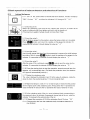
IM P O RT A NT S A F ET Y ' N ST R U C T IO N S
R e a d t h e s e s a f e t y i n s t r u c t i o n se n t i r e l y !
R e a d a n d u n d e r s t a n da l l s a f e t y i n s t r u c t i o n sb e f o r eo p e r a t i n gm a c h i n e
Precautionin installationand operation
*Don' t plac e t he d e te c to ri n a n e x tre meh o t o r col d
condi ti on,and avoi dsetti ngthe machi necl oseto the heat ing
r adiat ort ,ap,air h u m i d i fi ear n d s to v e s .
" Don' tplac et he d e te c to n
r e a rth e w i n d o wu n d e rthe
di rectsunshi ne.l n caseof i nevi tabl e,
the w i ndowcurtai n,
shieldand hood shouldbe usedto shadethe detector.
*No c ont ac of
t t h e ma c h i n ei s a l l o w e dw i th
d u s t,a mmoni um,
al coholdi
, l uentsand pul veri zed
adhesi ve,
etc.
*T hedet ec t ors h o u l db e i n s ta l l e d
o n a l e v e l e dg r ound.
"Neverplaceit closeto the air compressor
or any substancethat may generatevibration.
*Duringthe operationdon'tcloseto the detectorunlessthe
operator.
*The dynamicbalancedetectorshoulduse separatedpower
socket.Don'tconnectany otherwire in this socket.
A t t ent ionm us tbe p a i dto th e re l i a b l eg ro u n d i n g,
i f therei s no groundi ng
connecti on
i n the socket,i t mustbe
addedbeforeconnectwith the powersource.
*T hewir e lineof d y n a mi cb a l a n c ed e te c to sr h o ul dbe prevented
fromsteppi ngon.
*A space of 50 cm width shouldbe left betweenthe wall
and detectorto ensurethe ventilation
for heat.Spacesalso
shouldbe lefton the leftand rightsidesof the machinefor operatorto operatethe machinewithoutobstacle.
*Contactwith the specialserviceman for maintenance
beforeyou haveto movethe dynamicbalancedetector.
Callyour."t|:.lrion,!othe follow,n,g.,lroblems
*Neverdismountor refitthe dynamicbalancedetectorby yourself.
*The part of rotationalshaftshouldbe preventedfrom
*The dynamicbalancedetectorcan be restartedonly
.On the top of dynamicbalancedetectorneverput
any strike.
5 secondslateraftershut down.
many heavysubstances.
*Please refer the content of self-calibration
in case of abnormaloperation.Cutoff the powersupplyand pullout the
plug immediately,
if the noise,smokeor any otheraccidentstake placesuddenly,then informthe relevantserviceman.
*ln front of the power socket of the
dynamicbalancedetector,spacemust be leftso that you can rapidlypullout the
plug.
*The dynamic balancedetectorcan't be used beyond the scopeof its functionsstipulatedin the manual.
l.TechnicalData
*1&q6ryn-rryaaE|ta
Max.wheelweight
Cycle time
70kg
<10s
Powersupply
22OV|11OV 50/60H2
Workingtemperature -5C---50C
Balancingfunction
DYNAMIC.STA. ALU1. ALU2. ALU3
Balancingprecision
1g
Rim diameter
10"--24"
Rim width
1.5"---20"
Net weight
150k9
2.Thebalanceweight plumb (block)used in the detector
2.lStackedpackageof balanceweightplumb.
(Ordinarysteelrim sectionand aluminumalloyrim section)
2.2stuckbalanceweightplumb.
(Aluminumalloyrim section)
Note: The errors in balance weight plumb directly affect the tesfed resutf of the detector.
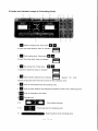
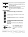
3.Maincomponentsof GB seriesdynamicbalancedetector
- - . . . T : , 1 F - 8 - . r - ' * * - - ' -
Side cover plate
( Side view )
t Front view )
(Side view)
2
4 . K n o b sa n d i n d i c a t o rL a m p s o n G o n t r o l l i n gP a n e l
1. tr
press
Distance
settins
knob.
down
EI tt
to adjustthe setteddistancevalueon indicator
@
lt-11
2.
II
Widthsetting
knob.pressdown
H
to adjustthe settedwidthvalueon indicator.
3. tr
Diasetting
knob.Press
down
rffir
lffl
TIIt
to adjustthe settedDia valueon indicat
or.
4. tr
H
@l
ll-11
Highprecision
balance
knob.Indicator
d i s p l a v s "0 0 " w h e n
unbalance<Sg,press
downthis knobto showthe left unbalancevalue.
5. E
Knobfor automatically
testthe inputtingvalue.
6. tr
Knobfor staticbalanceand selectingthe position& modeof ALU balancingblock.
t
Knobfor emergencyshutdown.
'E''ry
E
Valuedisplayindicator.
11.12'ffiPositioninglampforunba|ancepoint'
Balancingblockmodeindicating
lamp.
3
:.'i:;1
1. fil
. "".i.:{j1.,;i
D i s t a n csee t t i nkgn o bP. r e s d
s o w n@
@
toadjustthesetteddistanceva|ueonindicator'G
2. m
w i d t hs e t t i nkgn o bp. r e s sd o w n@
t o a d j u s tt h e s e t t e dw i d t hv a l u eo n i n d i c a t o r
3. lil
@
]||:l
knob.
Press
down@
Diasettins
@
t o a d j u stth es e t t e dD i av a l u eo ni n d i c a t o r
{!Fl
4.@Highprecisionba|anceknob.|ndicatorGdisp|ayS,,00,,when
u n b a l a n c e < 5 9p,r e s sd o w nt h i s k n o bt o s h o wt h e l e f tu n b a l a n c ev a l u e .
5.
6.
I
I
7.
8.
K n o bf o r s t a t i cb a l a n c ea n d s e l e c t i n gt h e p o s i t i o n& m o d eo f A L U b a l a n c i n gb l o c k .
g
g,
9 . 10 .
11.12.
13.
K n o bf o r a u t o m a t i c a l ltye s tt h e i n p u t t i n gv a l u e .
K n o bf o r e m e r g e n c ys h u td o w n .
S t a r t i n gk n o b .
V a l u ed i s p l a yi n d i c a t o r .
P o s i t i o n i n lga m pf o r u n b a l a n c ep o i n t .
lamp.
B a l a n c i n gb l o c km o d ei n d i c a t i n g
4
5 . B a s i c o p e r a t i o n o f b a l a n c ed e t e c t o r a n d s e l e c t i o no f f u n c t i o n s
5 . 1(
) w h e e lb a l a n c e r
@
5.1.1 Turn on the powerswitchon the leftsideof the detector,indicator9 displays
" C 8 2 " 1 0 s h o w " 0 0 " a n d t h e nt h e i n d i c a t o r9s, 1 0c h a n g et o " A " ," 8 . 0 "
,
,
5 . 1 . 2M o u n t i n go f t i r e
Select the positioningcone that fits the central hole of the rim,to installit at the
centerof rotational
shaft,thentightenand lockit withthe handlenut.
( T h e m a x i m u mw e i g h to f w h e e l s h o u l dn o t m o r e t h a n 7 0 k 9 . )
5 . 1. 3 I n p u t h e v a l u eA
Pullthe distancegaugeA to the position,wherethe balanceblockis to be setted.
Press EI E
knobs and input the readingon the gaugeintoindicator10,
'' t'
meanwhilethe indicator9 shoulddisplaythe valueas A
5 . 1 . 4I n p u t h e v a l u eL
Use the widthgaugethat takenfrom the accessoriesto measurethe width between
two sidesof the rim,pressII ll
XnoOs
to inputthe readingon the gaugeintothe
'r
i n d i c a t o1r 0 , m e a n w h i l teh e i n d i c a t o r gs h o u l dd i s p l a y t h ev a l u ea s , L
5 . 1 . 5I n p u t h e v a l u eD
Afterthe valueof Dia.confirmed,pressII E nobsto inputthe valueintothe
indicator10, meanwhilethe indicator9 shoulddisplaythe valueas " D ''
w
5.1.6 Pressthe startingknob to startthe operation;severalsecondslater,the
detector wil I automaticallystop. (Pulldown the protectionhood, the detector
of B type will automaticallystart up.)
5 . 1 . 7D i s p l a yt h e u n b a l a n c vea l u e
The value displayedby indicators
9 and 10 is the valueof unbalance,
rotatethe
wheelby hand,the positioning
lamps11,12will constantly
flash.
5 . 1 . 8R i g h t t i lal l l l a m p si n a s e t o f 1 1 o r 1 2 s t a r t t ol i g h t ,i t m e a n st h a tt h e p o s i t i o n
of rim'shighestpointis the unbalancepoint.Amongwhichthe 11 represents
the
valueof internalrim sideand the 12 represents
the valueof externalrim side.
5.1.g.Atthe unbalancepointof the rim,mounta balanceblockcorresponding
to
the measuredvalue,the indicator9 represents
internalsideof the rim,whilethe
indicator10 represents
the externalsideof the rim.
"
"
procedure
5.1.10 Repeatthe
6-10 till the indicators9 and 10 show 00
5.1.11 Dismountthe tire from the rotationalshaft.the balancedetectionis
nowfinished.
5
I
Selectionof functions
This lamp lightingshows that it is adapt to the tires used for motorcycle,or those wheels
at both sides of which placingthe balanceblock is not allowed.
T h i s l a m p l i g h t i n gs h o w st h a t i t i s a d a p tt o t h e a l l o yr i m ,a t t h e s h o u l d e ro f w h i c ht h e
b a l a n c eb l o c kc a n b e s t u c ko n .
T h i s l a m p l i g h t i n gs h o w st h a t i t i s a d a p tt o t h e a l l o yr i m ,o n t h e e x t e r n a hl i d d e ns i d e o f
w h i c ht h e b a l a n c eb l o c kc a n b e s t u c ko n .
E
T h i s l a m p l i g h t i n gs h o w st h a t o n t h e e x t e r n a sl i d e o f w h i c ht h e b a l a n c eb l o c kc a n b e
stuck on, and at the internalside of the rim, the balanceblock can be bracedor
inserted.
When the four sets of indicatorsall went out, it shows the standardbalance.(When
ever you start the detector,the computerautomaticallyset at such state.)
5.2(
)WHEEL BALANCER
5.2.1Turn on the power switch on the front panel.
The indicator9 displays"850"andthen indicators
9.'10changeinto"A","8.0".
5 . 2 . 2M o u n t i n go f t i r e :
Selectthe positioning
conethatfitsthe centralholeof the rim,to installit at the centerof
rotational
shaft,then tightenand lockit withthe handlenut.
(The maximumweightof wheelshouldnot morethan 70kg)
5 . 2 . 3 I n p u t h e v a l u e" A "
Pullthe distancegaugeA to the position,wherethe balanceblockis to be setted.
PressG|
knobsand inputthe readingon the gaugeintoindicator',|0,
Gt
meanwhilethe indicator9 shoulddisplaythe valueas "A"
5 . 2 . 4 I n p u t h e v a l u e" L "
U s e t h e w i d t hg a u g et h a tt a k e nf r o mt h e a c c e s s o r i e tso m e a s u r et h e w i d t h
b e t w e e nt h e t w o s i d e so f t h e r i m , p r e s s @
k n o b st o i n p u tt h e
Gf
m e a s u r e dw i d t hi n t oi n d i c a t o1r 0 ,m e a n w h i l e
i n d i c a t o9r s h o u l dd i s p l a yt h e
v a l u ea s " L "
5 . 2 . 5 I n p u vt a l u e" D "
A f t e rt h ev a l u eo f r i mD i ac o n f i r m e dp,r e s s@
Gf
k n o b st o i n p u t h e
v a l u ei n t ot h e i n d i c a t o 1
r 0 , m e a n w h i l et h e i n d i c a t o 9r s h o u l dd i s p l a yt h e
"
D
"
.
v a l u ea s
5 . 2 . 6P r e s s t h e s t a r t i n g k n o b t o s t a r t t h e o p e r a t i o n .
7 secondslaterafterstarting,the detectorwill automatically
stop.(Pulldown
the protectionhood,the detectorof B type will automatically
startup.)
5 . 2 . 7D i s p l a yt h e v a l u e o f u n b a l a n c e
The valuedisplayedby indicators
9 and 10 is the valueof unbalance.Rotate
lamps11 and 12 will constantly
the wheelby hand,the positioning
flash.
6
ffiross
5 . 2 . 8 R i g htti l la l l l a m p si n a s e t o f 1 1 o r 1 2 s t a r tt o l i g h tt h a t m e a n st h e
h i g h e s tp o i n to f r i m i s t h e u n b a l a n c ep o i n t .A m o n gw h i c ht h e i n d i c a t o 1r 1
r e p r e s e n t st h e v a l u eo f i n t e r n a sl i d e o f t h e r i m a n d t h e 1 2 r e p r e s e n t st h e
v a l u e o f e x t e r n a ls i d e o f t h e r i m .
5.2.9At the unbalancepointof the rim,mounta balanceblockcorresponding
to the measuredvalue.The indicator9 representsinternalside of the rim,
whilethe indicator10 represents
the externalsideof the rim.
procedures
5.2.10Repeatthe
6-10 untillthe indicators
9 and 10 show"00"
5.2.11Dismount
the tire from the rotationalshaft.the balancedetectionis now
finished
S e l e c t i o no f f u n c t i o n s
tEl
I
IELII
| --)I
r-tr
t
-
l
t
-
t
I
This lamp lightingshowsthat it is adaptto the tiresthat usedfor motorcycles,
or
thosewheelson both sidesof which placingthe balanceblockis not allowed.
|
I
I
B
[--I
I
I lEltr
I
r-tr
I
I
t
l-!r
-
I
t
-
I - I I
I
-
I
This lamplightingshowsthat it is adaptto the alloyrim,at the shoulderof whichthe
balanceblockcan be stuckon.
Thislamplightingshowsthatit adaptsto the alloyrim,on the hiddenexternal
sideof whichthe balanceblockcan be stuckon.
I
t
t
I
I tEtt
I lrrl
I
I
I
t - l
Thislamplightingshowsthaton the externalsideof whichthe balanceblock
can be stuckon, and on the internalsideof the rimthe balanceblockcan be
bracedor inserted.
Whenthe foursetsof the lampsall wentout,it showsa stateof standard
balance(Wheneveryou startthe detector,
the computerwill automatically
set at suchstate.)
positioning
6.Gounter
:r'.::.:eFa!.F1€;!..-=:;{.1a.:€ir!:+!=gt*+..:*.
Counterpositioningmethodis a widelyused
method.lt is applicable
to commonsteel rims
#-m€rr+
and aluminumalloyrims. Especiallyfor the
new rims, and it can providehigh balance
precision.
Proceduresof counterpositioning:
Place the springwith the
bottomtowardthe balance
ro**l*F;;l
-ffi-*l
suitablecone
wneet
I
|
7
|
| |
|
Q u i c kb o l t
cap
7.Self-calibration
W h e n t h e r e i s d o u b t i n t h e p r e c i s i o no f t h e m e a s u r e dv a l u et h i s f u n c t i o nc a n b e u s e d .D o n ' ts h u t
d o w n t h e d e t e c t o rd u r i n gt h e o p e r a t i o n b, e c a u s ei t m a y c a u s et h e i n p u t t i n go f t h e w r o n gv a l u e .
( D o n ' ta r b i t r a r i l yu s e t h i s f u n c t i o n )
P r o c e d u r e si n o p e r a t i o n :
@+@
1 , M o u n tt h e b a l a n c e dt i r e .
2 . P r e s sd o w nt h e " R " k n o b ,a f t e r a b o uht a l fa s e c o n d p, r e s s t h e
s t a r t i n g k n o b . T h e i n d i c a t o r s 91a0ns dh o w " C A L " - " C A L " , t h e
p o s i t i o n i nlga m po f u n b a l a n c w
e i l l f l a s hs e v e r a l s e c o n d a
s ,n d t h e n
w e n to u t a u t o m a t i c a l l y .
3 . P r e s sd o w nt h e s t a r t i n gk n o b ,a f t e rs e v e r a sl e c o n d st h e d e t e c t o r
a u t o m a t i c a l lsyt o p ,t h e i n d i c a t o r 9
s a n d 1 0 s h o w " A d d " - ' t 1 0 0"
A d d a b a l a n c eb l o c ko f 1 0 0 9a t a n y p o i n to f e x t e r n a sl i d eo f t h e r i m .
4 . P r e s s t h i sk n o b ,t h e w h e e lw i l lr o t a t e t, h e i n d i c a t o r9s a n d 1 0 s h o w
" E n d " - " C A L "t ,h e c a l i b r a t i o ins
complete.
S.Standardaccessoriesof GB SeriesTire DynamicBalanceDetector
c
*.
Positioning
conesfor axis
Thread rod
{F
egc
Plumb100g
fr
\\
nip
Countenrueight
Q u i c kb o l t c a p
Calipers
Spring
Plasticcup
9.Optionalaccessoriesof CB Series Tire Dynamic Balance Detector
Protection
cover
Extra-large
cone
8
flange
'
t
t
t:,
10.Standardaccessories(List)
.
: . ' ,
. : .
:
. ' i l i
-
: '
_
: . : :
.
.
: - ' , -
,
, .
*Counterweightnip
* Caliper
*Positioningcone for axis
*Q uic k bolt c ap
*Thread rod
*P lum b l00g
*P las t ic c up
*S pr ing
lPiece
lPiece
3Picccs
lPiecc
lPiece
I Piece
lPiece
lPiece
1 1 . C o d ei n C o m p u t e rSelf-diagnosisof CB Seri.gsBalance Detector
Trouble in phasegeneratoror power plate, replace it.
Rotation speedis too low or wheel hasn'tbeen mounted (with tire).
Too big unbalance,try other wheel
Errors in power system,rotational direction is not right.
Nonsense.
Memory damagedor signal lost, calibrate again or renovate.
The procedureof calibrationis not appropriateor computerplate or sensordarnaged.
l2.Troubleshooting
Svmptom
Gause
No displayon the screenafter
starting
1.Externalpowermalfunction.
2.Powerplatemalfunction
3.Loosenconnectionbetween
computerplateand power plate.
4. Computerplatemalfunction.
l .C heckthe externalpow ersup ply
2.Replacethe powerplate.
3.C heckthe pl ugof the connect ing
line.
4.R epl ace
the computerpl ate.
1.Theconnectionof the switchis
n o tw el l .
2 .D e adcomputer.
1.Openthe coverand ti ghtenth e
plugof the touchswitch.
2.S tartthe machi neagai n.
T he dis playi s n o rma l b
, u t th e
brakedoes not work.
1.Loosenconnectionbetween
computerplateand powerplate.
2.Powerplatemalfunction
3.Computerplatemalfunction.
l .Ti ghtenthe connecti ng
l i ne
betweenthe computerplateand
the powerplate.
2.Replacethe powerplate.
3. Replacethe computerplate.
The startingis slowwith failure
in br ak ingan d i mp re c i s i oinn
balanc e.
Drivingbelt is too loose.
Adjustthe positionof the motoror
changethe dri vi ngbel t.
T he oper at io ni s n o rm a l b
, u t th e
balancevalueis not accuracy.
1 .T h ebodyof machi nei s pl aced
unstably.
2.Affectedby the cone or quick
boltcap.
3.Thewheelis not mountedtiohtlv.
4.Thepowersupplyinsidethema chi nei s unstabl e.
5.Powervoltagefluctuateviolently.
val uechanged.
6 .T h ecal i brati on
7 . T h e val uei nsi dethe machi ne
c h a nged.
1.Getri d of the probl em,according
to the testingresult.
2.R e-ti ghten
the qui ckbol tcap.
3.C heckthe pow ersuppl y.
4.Theoperatorcan adjustthe power
supplyby self.
5.Replacethe computerplateif
necessary.
6.Re-calibrate
it accordingto the
U ser' sManual .
T . l n p utth e d a t ao f d i s , l n - l , S FaAg a i n ,
accordingto the markson the
machi ne,then
cal i bratei t againt o
checki f the machi new ork no r m ally.
T he dis playis n o rma l ,b uth
t e
startingswitchand the inputing
k nobsheadsA .L .Ci s m a l fu n c ti o n
9
Solution