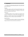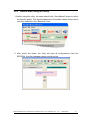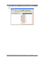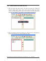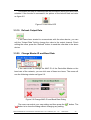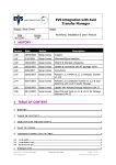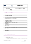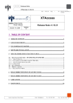
1
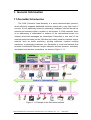
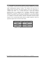
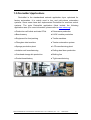
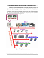
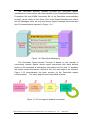
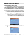
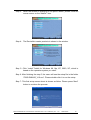
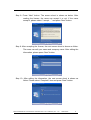
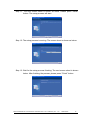
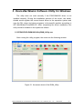
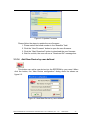
DeviceNet Master Utility
User’s Manual
Warranty
All products manufactured by ICP DAS are warranted
against defective materials for a period of one year from the
date of delivery to the original purchaser.
Warning
ICP DAS assumes no liability for damages consequent
to the use of this product. ICP DAS reserves the right to
change this manual at any time without notice. The
information furnished by ICP DAS is believed to be accurate
and reliable. However, no responsibility is assumed by ICP
DAS for its use, or for any infringements of patents or other
rights of third parties resulting from its use.
Copyright
Copyright 2008 by ICP DAS Co., LTD. All rights
reserved worldwide.
Trademark
The names used for identification only may be
registered trademarks of their respective companies.
DeviceNet Master Utility User’s Manual (Ver: 1.0)
2008/02/25
1
Contents
1.
GENERAL INFORMATION .................................................................................3
1.1 DEVICENET INTRODUCTION .......................................................................................3
1.2 DEVICENET APPLICATIONS .........................................................................................5
1.3 DEVICENET MASTER SERIES PRODUCT CHARACTERISTICS...........................................6
2.
WINDOW SYSTEM DRIVER INSTALLATION ...............................................9
2.1 Driver Installation of the PISO-DNM100 ...........................................................9
3.
DEVICENET MASTER SOFTWARE UTILITY FOR WINDOWS ....................14
3.1 INTRODUCTION .......................................................................................................15
3.2 TUTORIAL DEMOS ...................................................................................................16
3.2.1 Where to find the Board Information...........................................................16
3.2.2 How to start using the utility........................................................................17
3.2.3 How to search the slave devices ..................................................................19
3.2.4 How to add I/O information into the EEPROM ..........................................21
3.2.5 How to read/write the I/O data form the slave device .................................22
3.3 DESCRIPTION OF THE BUTTONS...............................................................................24
3.3.1 Total Board Number ....................................................................................24
3.3.2 Board Number..............................................................................................24
3.3.3 Active Board ................................................................................................24
3.3.4 Exit...............................................................................................................24
3.3.5 Reset Firmware ............................................................................................25
3.3.6 Search All Device ........................................................................................25
3.3.7 Diagnose Specific Device ............................................................................25
3.3.8 Start All Device ...........................................................................................25
3.3.9 Stop All Device............................................................................................26
3.3.10 Clear the EEPROM....................................................................................26
3.3.11 Export from EEPROM...............................................................................26
3.3.12 Import into EEPROM ................................................................................26
3.3.13 Update New Firmware...............................................................................26
3.3.14 Add New Device by user-defined..............................................................27
3.3.15 Add New Device........................................................................................28
3.3.16 Remove the I/O connection .......................................................................28
3.3.17 Start Device................................................................................................28
3.3.18 Stop Device................................................................................................28
3.3.19 Refresh Output Data ..................................................................................29
3.3.20 Change Master ID and Baud Rate .............................................................29
DeviceNet Master Utility User’s Manual (Ver: 1.0)
2008/02/25
2
1. General Information
1.1 DeviceNet Introduction
The CAN (Controller Area Network) is a serial communication protocol,
which efficiently supports distributed real-time control with a very high level of
security. It is an especially suited for networking "intelligent" devices as well as
sensors and actuators within a system or sub-system. In CAN networks, there
is no addressing of subscribers or stations in the conventional sense, but
instead, prioritized messages are transmitted. DeviceNet is one kind of the
network protocols based on the CAN bus and mainly used for machine control
network, such as textile machinery, printing machines, injection molding
machinery, or packaging machines, etc. DeviceNet is a low level network that
provides connections between simple industrial devices (sensors, actuators)
and higher-level devices (controllers), as shown in Figure 1.1.1.
Figure 1.1.1 Example of the DeviceNet network
PISO-DNM100 DeviceNet Master API functions User’s Manual (Ver: 1.0)
2008/02/25
3
DeviceNet is a cost effective solution to one kind application of control
c\area network. It reduces the connection wires between devices and provides
rapid troubleshooting rejection function. The transfer rate can be up to
500Kbps within 100 meters. The transfer distance can be up to 500 meters in
125Kbps (See Table 1.1.1). It allows direct peer to peer data exchange
between nodes in an organized and, if necessary, deterministic manner.
Master/Slave connection model can be supported in the same network.
Therefore, DeviceNet is able to facilitate all application communications based
on a redefine a connection scheme. However, DeviceNet connection object
strands as the communication path between multiple endpoints, which are
application objects that is needed to share data.
Baud rate (bit/s)
Max. Bus length (m)
500 K
100
250 K
250
125 K
500
Table 1.1.1 The Baud rate and the Bus length
PISO-DNM100 DeviceNet Master API functions User’s Manual (Ver: 1.0)
2008/02/25
4
1.2 DeviceNet Applications
DeviceNet is the standardized network application layer optimized for
factory automation. It is mainly used in low- and mid-volume automation
systems. Some users have also implemented DeviceNet for machine control
systems. The main DeviceNet application fields include the following
application area (For more information, please refer to www.odva.org):
● Production cell builds and tests CPUs
● Dinnerware production
● Beer brewery
● HVAC module production
● Equipment for food packing
● Textile machines
● Fiberglass twist machine
● Trawler automation system
● Sponge production plant
● LCD manufacturing plant
● Isolation wall manufacturing
● Rolling steel door production
● Overhead storage bin production
● Bottling line
● Pocket-bread bakery
● Tight manufacturing
PISO-DNM100 DeviceNet Master API functions User’s Manual (Ver: 1.0)
2008/02/25
5
1.3 DeviceNet Master Series Product Characteristics
Users don’t need to take care of the detail of the DeviceNet protocol. The
firmware inside the product mainly supports the Predefined Master-Slave
Connection Set and UCMM functions to allow users to merge third party’s
DeviceNet devices into the DeviceNet network. It can help users to establish
the connection with DeviceNet slave devices easily. The general application
architecture is demonstrated as Figure 1.3.1
Figure 1.3.1 Application architecture
PISO-DNM100 DeviceNet Master API functions User’s Manual (Ver: 1.0)
2008/02/25
6
The DeviceNet protocol firmware provides the DeviceNet Master
mechanism to communicate with slave devices by the Predefined Master/Slave
Connection Set and UCMM Connection Set. In the DeviceNet communication
protocol can be clarify as two forms: One is the Explicit Message and others
are I/O Messages. Here, we only provide one explicit message connection and
four I/O connections as depicted in Figure 1.3.2
Figure 1.3.2 DeviceNet Messaging
The DeviceNet Communication Protocol is based on the concept of
connections method. Master should create connections with slave devices
based on the command of exchanging information and I/O data. To establish
the master control mechanism, there are only four main steps to be followed.
Figure 1.3.3 demonstrates the basic process for the DeviceNet master
communication. The every step function is described in below:
Figure 1.3.3 Four steps to establish connection
PISO-DNM100 DeviceNet Master API functions User’s Manual (Ver: 1.0)
2008/02/25
7
1. Add device into firmware
You should provide the slave device’s MAC ID to add into firmware.
2. Configure connection
You can check the slave device’s I/O connection type and the I/O data
length. When configuring the I/O connection, you should provide these
parameters.
3. Start Device
After configuring connections, users should start device to establish the
connection between the master and the slave devices.
4. Access I/O data
After communicating with slave devices, you can access the I/O data with
corresponding read/write function.
PISO-DNM100 DeviceNet Master API functions User’s Manual (Ver: 1.0)
2008/02/25
8
2. Window System Driver Installation
2.1 Driver Installation of the PISO-DNM100
The software Installation for DeviceNet application is demonstrated as the
following descriptions. After finishing the procedure, the driver, demos, manual
and Utility can be installed in your PC. Users can refer to demo program and
follow its hardware application structure to test the basic functions of
master/slave connection. For the advance application, users can refer to the
basic demo programs to develop customization DeviceNet master application.
The driver of PISO-DNM100 can be used in 98/Me/NT/2000/XP Windows
environments. For these Windows operation systems, the recommended
installation procedure is given as follows:
Step 1: Insert the companion CD into the CD-ROM driver and wait a few
seconds until the installation program starts automatically. If it cannot
be started automatically for some reason, please double-click the file
ICPDAS.EXE on this CD. The screenshot likes the following picture.
Please click “CAN Series” item.
Step 2: After changing to the following picture, please click the “DeviceNet”
item.
PISO-DNM100 DeviceNet Master API functions User’s Manual (Ver: 1.0)
2008/02/25
9
Step 3: When the window is changing to the picture below, please move the
mouse cursor on the “Master” item.
Step 4: The DeviceNet master products is shown in the window.
Step 5: Click “install Toolkit for Windows 98, Me, NT, 2000, XP, which is
based on the operation system you used”.
Step 6: After finishing the step 5, the users will see the setup file in the folder
“PISO-DNM100_V10.exe”. Please double-click it to run the setup.
Step 7: This first setup screen shoot is shown as follow. Please press “Next”
button to continue the process.
PISO-DNM100 DeviceNet Master API functions User’s Manual (Ver: 1.0)
2008/02/25
10
Step 8: Press “Next” button. The screen shoot is shown as below. After
reading the license, the users can accept it or not. If the users
accept it, please select “I accept….” and press “Next” button.
Step 9: After accepting the license, the next screen shoot is shown as follow.
The users can edit your name and company name. After editing the
information, please press “Next” button.
Step 10: After editing the information, the next screen shoot is shown as
follow. Please select “Complete” item and press “Next” button.
PISO-DNM100 DeviceNet Master API functions User’s Manual (Ver: 1.0)
2008/02/25
11
Step 11: The next screen shoot is shown as follow. Please press “Install”
button. The setup process will start.
Step 12: The setup process is running. The screen shoot is shown as below.
Step 13: Wait for the setup process finishing. The next screen shoot is shown
below. After finishing the process, please press “Finish” button.
PISO-DNM100 DeviceNet Master API functions User’s Manual (Ver: 1.0)
2008/02/25
12
Step 14: The next screen shoot is shown as follows. Please restart your PC.
Then the setup copies the related material to the indicated directory and
registers the driver on your computer. The driver target directory below is for
the different systems.
Windows NT/2000 – WINNT\SYSTEM32\DRIVERS
Windows 98/Me/XP – WINDOWS\SYSTEM32\DRIVERS
The other data and resource are copied to the following directory:
C:\ICPDAS\PISO-DNM100\
The program files picture is shown as follow.
PISO-DNM100 DeviceNet Master API functions User’s Manual (Ver: 1.0)
2008/02/25
13
3. DeviceNet Master Software Utility for Windows
The utility does not work normally if the PISO-DNM100 driver is not
installed correctly. During the installation process of the driver, the installshields would register the correct kernel driver to the operation system and
copy the DLL driver and demo programs to the specific position according to
OS (Win98,Me,NT,win2000,XP). After completing the driver installation, the
utility would be installed in the system as follows.
C:\ICPDAS\PISO-DNM100\Utility\DNM_Utility.exe
After running the utility program, the users see the following window.
Figure 3.1 the screen shoot of the DNM_Utility
PISO-DNM100 DeviceNet Master API functions User’s Manual (Ver: 1.0)
2008/02/25
14
3.1
Introduction
The software utility includes various useful functions. These functions help
users to diagnose and access the DeviceNet devices. There are three main
parts of these functions.
- Diagnosis
This utility supports to search all devices and specific devices in the
network. These functions help the users to configure the connection of the
slave devices. Anymore, the software also can diagnose the remote slave
devices when building the DeviceNet network.
- Configuration
This software supports the users to configure the I/O connection of the
devices by searching devices or manual setting. After configuring the I/O
connection, the information would be saved into the EEPROM of the PISODNM100. The users can export the data from the EEPROM easily.
Correspondingly, the users can import the data into the EEPROM.
- Remote I/O access
The software utility can easily to access the I/O data of all the slave
devices. The users can monitor the input data of the specific slave device and
change the output data to the remote slave device with this utility.
PISO-DNM100 DeviceNet Master API functions User’s Manual (Ver: 1.0)
2008/02/25
15
3.2
3.2.1
Tutorial Demos
Where to find the Board Information
1. The utility would search the number of boards in your PC automatically. It
shows the count of the boards which have been found.
2. The utility also lists the ID of all boards in the “Board No” field.
PISO-DNM100 DeviceNet Master API functions User’s Manual (Ver: 1.0)
2008/02/25
16
3.2.2
How to start using the utility
1. Before using this utility, the users should click “ActiveBoard” button to active
the specific board. That would initialize the DeviceNet master device which
you have selected in the “Board No” field.
2. After active the board, the utility will read all configurations from the
EEPROM. And the message window would pop-up.
PISO-DNM100 DeviceNet Master API functions User’s Manual (Ver: 1.0)
2008/02/25
17
3. After reading the configuration from EEPROM of PISO-DNM100
successfully, the utility shows the information in the “Devices in EEPROM”
field.
PISO-DNM100 DeviceNet Master API functions User’s Manual (Ver: 1.0)
2008/02/25
18
3.2.3
How to search the slave devices
1. After the board has been active, the users can press the “Search all
Devices” button shown below. As the users press the button, the screen
shows a waiting dialog. It takes about 30 seconds to search the whole slave
devices in the network. The number of devices been scanned is 64.
2. After the searching procedure finishing, the utility shows the information of
all the slave devices in the “Searched Devices” field.
PISO-DNM100 DeviceNet Master API functions User’s Manual (Ver: 1.0)
2008/02/25
19
3. The users can expand the device to find out more I/O connection information
of those devices. The users can use this I/O information to develop your
configuration in the EEPROM.
PISO-DNM100 DeviceNet Master API functions User’s Manual (Ver: 1.0)
2008/02/25
20
3.2.4
How to add I/O information into the EEPROM
1. Please active your board or refer to section 3.2.2
2. Please search all devices or refer to section 3.2.3
3. Please select one of the I/O connection items in the device. And press the
“Add current I/O connection” button to add the I/O information into the
EEPROM.
4. If the mission is successful, the users would see the successful message
below. And you can find the selected item has been added into the
EEPROM field.
PISO-DNM100 DeviceNet Master API functions User’s Manual (Ver: 1.0)
2008/02/25
21
3.2.5
How to read/write the I/O data form the slave device
1. If the users have no I/O configuration in the EEPROM, please refer to
section 3.2.4 to add at least one I/O configuration.
2. Please press “Start all Device” button to communicate with all slave devices.
The warning message would pop-up. In this example, we can ignore it.
3. The users can click “Remote Device I/O Monitor” page to view the I/O data
of the slave devices.
PISO-DNM100 DeviceNet Master API functions User’s Manual (Ver: 1.0)
2008/02/25
22
4. The users can press the icon picture to display the device information,
including the device name and input data.
5. The users can press “Refresh output data” button to send the output data to
the slave device.
PISO-DNM100 DeviceNet Master API functions User’s Manual (Ver: 1.0)
2008/02/25
23
3.3
Description of the Buttons
Here is the description of the buttons in the software utility.
3.3.1
Total Board Number
This field shows the total board number of total boards in the PC. It will
detect the boards automatically when running this software. If the number is 0,
the users can not use this software. Please check the driver of the PISODNM100.
3.3.2
Board Number
There is a DIP-Switch on the PISO-DNM100. The number of the DIPSwitch is called “Board No”. The drop-down list will show the DIP-switch
number of all boards in the PC. The users can select a board number to be
active.
3.3.3
Active Board
This button can active the board which is selected in the “Board No” field.
The users should click this button before using other functions. (Except for
“Update New Firmware”)
3.3.4
Exit
This button will exit the utility.
PISO-DNM100 DeviceNet Master API functions User’s Manual (Ver: 1.0)
2008/02/25
24
3.3.5
Reset Firmware
This button can restart the firmware of the PISO-DNM100. If the users
have changed the master’s ID or baud rate, you must restart firmware to make
change enable.
3.3.6
Search All Device
This button can search all the slave devices in the network.
Notice: When the master is communicating with the slave devices, please don’t
use this function to avoid breaking the connection to the slave devices.
3.3.7
Diagnose Specific Device
This button can diagnose the specific slave device in the network.
Notice: When the master is communicating with the slave devices, please don’t
use this function to avoid breaking the connection with the slave devices.
3.3.8
Start All Device
This button can start to communicate with all slave devices which have
configured in the EEPROM.
Notice! If the slave device contains output channels and the initial output value is
not set, the master will send default value (0) to the output channels.
PISO-DNM100 DeviceNet Master API functions User’s Manual (Ver: 1.0)
2008/02/25
25
3.3.9
Stop All Device
This button would disconnect the communication with all slave devices
which have configured in the EEPROM. All remote slave devices will change to
the “off-line” state.
3.3.10
Clear the EEPROM
This button can clear all configuration data in the EEPROM. The MAC ID
of the master would be reset to 0 and the baud rate reset to 125K bps.
3.3.11
Export from EEPROM
This button can export the information from the EEPROM of the PISODNM100. The information will be saved a file (*.EEP).
3.3.12
Import into EEPROM
This button can import the EEP file into the EEPROM of the PISODNM100 from the specific EEP file.
3.3.13
Update New Firmware
This button can update the firmware of the PISO-DNM100. If ICPDAS
have new version of the firmware, the users can click this button to update it.
After clicking the button, the users can see the following window as figure 6.2.
PISO-DNM100 DeviceNet Master API functions User’s Manual (Ver: 1.0)
2008/02/25
26
Figure 6.2 Update Firmware
Please follow the steps to update the new firmware.
1. Please select the board number in the “BoardNo” field.
2. Click the “New Firmware” button to open the new firmware.
3. Click the “Start Download” button to download the new firmware.
4. Wait for a while, the user will see a “Download OK” message box.
3.3.14
Add New Device by user-defined
This button can add a new device into the EEPROM by your need. When
click the button, the “New Device configuration” dialog would be shown as
figure 6.3.
Figure 6.3 Add New Device by user-defined
PISO-DNM100 DeviceNet Master API functions User’s Manual (Ver: 1.0)
2008/02/25
27
3.3.15
Add New Device
This button can add an I/O connection of the device into the EEPROM
from the searched devices. The user must select an I/O connection item of
certain device and then click this button to add an I/O connection of the device
into the EEPROM.
3.3.16
Remove the I/O connection
This button can remove an I/O connection of the device from the
EEPROM.
The users should select an I/O connection item of certain device in the
EEPROM area and then click this button to remove an I/O connection of the
device from the EEPROM.
3.3.17
Start Device
This button can start to communicate with the selected devices. If the
function is successful, the information will be showed in the “DeviceName” field
and “Input Data” field and then the picture of the led will become green color as
figure 6.4.
Notice: If the users want to set an initial value to the output channel, you can
edit the value in the “Output Data” field the press the “Start Device”
button. During editing the output value, please follow the format in the
edit box.
Figure 6.4 Green color LED
3.3.18
Stop Device
PISO-DNM100 DeviceNet Master API functions User’s Manual (Ver: 1.0)
2008/02/25
28
This button can stop to communicate with the device which the users have
selected. If the function is successful, the picture of the led will flash red color
as figure 6.5.
Figure 6.5 Red color LED
3.3.19
Refresh Output Data
If the users have started to communicate with the slave device, you can
edit the “Output Data” field to change the value to the output channel. Finish
editing the value, press the “Refresh” button to send the new data to the slave
device.
3.3.20
Change Master ID and Baud Rate
If the users want to change the MAC ID of the DeviceNet Master or the
baud rate of the network, you can click one of these two items. The users will
see the following window as figure 6.6.
Figure 6.6 Change MAC ID and Baud Rate Dialog
The users can select your own setting and then press the “
“
” button. The
” button is to close the dialog without changing any setting.
PISO-DNM100 DeviceNet Master API functions User’s Manual (Ver: 1.0)
2008/02/25
29