1
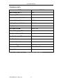
Instruction Manual
MIG WELDER
Instruction Manual
MIG 130 TURBO
USER MANUAL * MIG 130
-1-
Instruction Manual
CONTENTS
GUARANTEE………………………………………………………………………..3
INTRODUCTION…………………………………………………………………….3
WARNING……………………………………………………………………………3
SAFETY………………………………………………………………………………4
TECHNICAL DATA……………………...………………………………………….5
INSTALLATION……………………………………………………………………..6
Connection to Mains Supply………………………………………………..6
Wire Reel Loading…………………………………………………………..6
PREPARATION FOR WELDING……………………...………………………..6-7
MAINTENANCE……………………………………………………………………..7
TROUBLESHOOTING……………………………………………..……………….7
WARRANTY……………………………………………………………………….7-8
USER MANUAL * MIG 130
-2-
Instruction Manual
GUARANTEE
We give our unreserved guarantee that the Inverter Welding and Cutting Power
Source series comply with IEC60974 international safety standard.
Maintenance for one year since the date of purchase.
INTRODUCTION
The compact machine is used for arc welding and has been designed
specifically for the MAG welding of carbon steel and low alloy steel with either
co2 or argon/co2 mixture shielding gas using solid or cored electrode wires.
This welder is also suitable for the MIG welding of stainless steel. Cored wires
can be used as an alternative for no shielding gas applications by adapting
the polarity of the torch to the wire manufacturers recommendations.
The welder is fitted with a flat power transformer compete with damping
inductor and Graetz bridge rectifier. In addition a direct current permanent
magnet gear-motor is installed in an accessible opening in the welder. This
gear-motor can take reels of up to 5Kg. The welder also has a torch
permanently connected and a return cable complete with earth clamp.
Power is adjusted by means of switches or a rotary switch. The wire speed is
controlled using the knob on the front panel. The welder can be set up either
for welding with solid wire and gas or with cored wire and no gas by means of
the terminals situated on the side of the welder or in the opening containing
the wire reel. A thermostat is fitted which protects the welder from overheating
caused by malfunctions or particularly heavy use.
WARNING
You may be faced with dangers during the course of welding, so please be
careful and read the manual carefully before working.
•
•
Only use welding tools of good quality.
People using this equipment should be qualified for welding.
USER MANUAL * MIG 130
-3-
Instruction Manual
SAFETY
•
•
•
•
•
•
•
•
•
Avoid direct contact with the welding circuit; the no-load voltage
supplied by the generator can be dangerous.
Unplug the mains supply before installation
Do not weld in the rain or in the sun.
Do not weld on any pressurised container.
Ensure your work place is free from any flammable materials
Provide adequate ventilation for the removal of welding fumes.
Always wear suitable protection for eyes and hands.
Wear body protection to protect your skin from the ultra-violet produced
by the arc.
Place the machine on a level surface to prevent overturning.
Electric shock
• Do not touch live electrical parts
• Check and be sure that the input power cable earth wire is properly
connected to the earth in the mains input plug.
• Insulate yourself from work and ground using dry insulating mats or
covers big enough to prevent any physical contact with the work or
ground.
Fumes
• Avoid a prolonged period in the fumes.
• When welding, make sure you are in a well-ventilated area to avoid
breathing in the fumes.
Arc-emission
• Wear suitable welding mask and clothing to protect your eyes and skin.
• Use suitable screen or curtain to shield the arc.
• The welding spatter may cause fire, so make sure that there are no
flammable materials near to the work place.
Noise
• Use approved earplugs or earmuffs if noise level is high.
• Warn others nearby about noise hazard.
USER MANUAL * MIG 130
-4-
Instruction Manual
TECHNICAL DATA
DATA
MIG 130
Main Voltage (AC) V
230
Frequency HZ
50/60
Input Capacity ± 60% KVA
2.2
No Load Voltage V
21-32
Welding Current ± 10% A
35 - 117
Duty Cycle %
15
Wire Spool (ø) MM
0.8KG 100
Power Settings (ø) MM
4
Flux Cored Wire (ø) MM
0.8-0.9
Wire For Steel (ø) MM
0.6-0.8
Wire For Aluminum
0.8
Insulation Class IP
H
Protection Degree
IP21S
Dimensions MM
585 x 255 x 375
Weight KG
28
Technical Specifications MIG130 MIG STAR 250
USER MANUAL * MIG 130
-5-
Instruction Manual
INSTALLATION
Set up the machine in an area where openings for cooling air are not
obstructed.
Connection to Mains Supply
Before making any electrical connection check that the mains voltage ratings
of the data table correspond with the voltage of the workplace. The machine is
to be fed with two conductors plus a third separate one designed for the
protective earth connection: this conductor is coloured yellow/green.
Wire Reel Loading
Make sure that the wire feed rollers, the wire guide hose and the contact tip of
the torch match the diameter and type of wire to be used and make sure that
these are fitted correctly.
Insert the wire reel onto the spindle making sure that the spindle pin is
correctly placed in its hole.
Release the pressure counter-roller and move it away from the lower roller.
Free the end of the wire and cut off the bent end making sure it has no burr.
Rotate the reel anti-clockwise and thread the end of the wire into the entrance
wire guide pushing it into the wire guide of the torch fitting for about 50100mm.
Reposition the counter roller and set the pressure at an intermediate value
and make sure that the wire is correctly positioned in the groove of the lower
roller. Use the adjustment screw to apply a slight braking pressure on the
spindle. Switch the welder on by turning the switch to (I) and press the torch
button. Wait for the end of the wire to go through the whole of the wire guide
hose and protrude by about 10 – 15cm from the front part of the torch and
then release the torch button.
Caution! During this operation the wire is live and subject to mechanical
stress; therefore if adequate precautions are not taken the wire could cause
electric shock injury and inadvertently striking of electric arc.
Check that wire feed is regular; set the roller and spindle braking pressure to
the minimum possible value. Making sure that the wire does not slide in the
groove and when feed is halted loops of wire are not loosened by excessive
reel inertia.
PREPARATION FOR WELDING
Connect the return cable to the work piece. If solid wire is used, open and
adjust the flow of shielding gas by means of the pressure reducer.
Note: Remember to shut the shielding as off when you finish work. Switch the
welder on and set the welding current by means of the switches or rotary
switch.
USER MANUAL * MIG 130
-6-
Instruction Manual
A protective mask must be worn during welding equipped with the correct
filtering glasses to protect the eyes from the light radiation produced by the
arc.
MAINTENANCE
Always disconnect from the mains supply before checking the welder.
Regularly inspect machine according to frequency of use and dustiness of the
work area. Remove dust inside the machine with a low-pressure airflow.
Check before every use the condition and correct assembly of the end parts
of the torch: nozzle, contact tip and gas diffuser.
Regularly check the condition of the wire feed rollers and remove any metallic
dust deposited in the feed area.
TROUBLESHOOTING
If you have any problems in setting up or operating, please first consult this
manual.
If you are still having difficulties after reading this manual, please contact
Inverter Fusion Ltd direct.
USER MANUAL * MIG 130
-7-
Instruction Manual
PRODUCT WARRANTY
September 2010
This limited warranty supersedes all previous Inverter Fusion Limited
warranties and applies to sales of Inverter Fusion Limited equipment in the
UK.
Warranty
Subject to the following terms and conditions, Inverter Fusion Limited
warrants to the original retail purchaser that new Inverter Fusion Limited
equipment sold in the UK is free of defects in material and workmanship at the
time of its despatch from Inverter Fusion Limited for the warranty period
advertised for the product at the time of sale.
Within the warranty period as listed, Inverter Fusion Limited will repair or
replace any warranted parts or components that fail due to such defects in
material or workmanship, provided the warranty has been registered at the
time of purchase.
Inverter Fusion Product Warranty shall not apply to:
• Consumable items and accessories supplied by Inverter Fusion Limited
but manufactured by others. These items will be covered by the
manufacturer’s warranty, if any.
• Electrodes, contactors and relays.
• Equipment that has been modified or repaired in any way
• Equipment that has been improperly installed, misused, improperly
operated, or used in a manner that does not comply with an industry
standard.
• Equipment that has been used for a purpose outside the specifications
for that equipment
• Equipment that has not been maintained in a condition that would
make it suitable for use.
• Equipment which has been used in conjunction with parts or
consumables which affect the equipment operation which are deemed
by Inverter Fusion Ltd to be of inferior quality or no fit for that purpose
In the event of a valid warranty claim being made on any Inverter Fusion
Limited product, the exclusive remedies shall be, at the discretion of Inverter
Fusion Limited, either the repair or replacement of the product
To the extent permitted by Law, the remedies provided herein are the sole
and exclusive remedies.
Inverter Fusion Limited liability under this warranty shall not exceed the cost
of correcting the defect. In no event shall Inverter Fusion Limited be liable for
USER MANUAL * MIG 130
-8-
Instruction Manual
direct, indirect, special, incidental or consequential damages (including loss of
profit), whether based on contract, tort, or any other legal theory.
Any express warranty not provided herein and any implied warranty,
guarantee, or representation as to the performance, and any remedy for
breach of contract, tort or any other legal theory which, but for this provision,
might arise by implication, operation of Law, Custom of Trade, or course of
dealing, including and implied warranty or merchantability for a particular
purpose, with respect to any and all equipment furnished by Inverter Fusion
Limited, is excluded and disclaimed by Inverter Fusion Limited.
Warranty Registration
In order for any warranty to be valid, the Warranty Registration Card enclosed
must be completed and returned at the time of purchase in order to register
the warranty with Inverter Fusion Limited. Alternatively the warranty may be
registered via the company’s website www.inverterfusion.com
Warranty Claims Procedure
In the event of a claim, the claimant must first contact Inverter Fusion Limited
for a warranty claim authorization number. Following this, the Warranty Claim
form, as printed on the reverse side of this page should be completed with all
the details as requested and forwarded to Inverter Fusion Limited at the
address below along with the faulty product and a copy of the original
purchase receipt. The claimant will be responsible for all carriage, insurance
and transportation costs in returning the product to Inverter Fusion Limited.
Upon receipt and inspection of the product, if valid the product will be repaired
or replaced at the discretion of Inverter Fusion Limited. In the event of a repair
being required that is not considered to be a warranty issue, the claimant will
be contacted for his further instruction.
Following the completion of any authorized warranty claim work, the product
will be returned to the original claimant at the cost of Inverter Fusion Limited.
(UK Customers Only)
Failure to comply with the above procedure could invalidate or delay the
completion of any warranty work.
Improper use, abuse or any attempt to repair the product by an unauthorized
third party will invalidate any warranty claim.
Inverter Fusion Ltd
Heathpark Way
Heathpark Industrial Estate
Honiton
Devon EX14 1BB
USER MANUAL * MIG 130
-9-