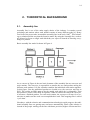
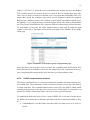
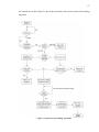
1
YANSONG GUO DESIGN AND IMPLEMENTATION OF A SERVICE-ORIENTED AUTOMATION FOR A STORAGE BUFFER Master’s thesis Examiner: Professor José Luis Martínez Lastra Examiner and topic approved by the Faculty Council of the Faculty of Automation, Mechanical and Materials Engineering on 7th November 2012. 1 ABSTRACT TAMPERE UNIVERSITY OF TECHNOLOGY Degree Programme in Machine Automation Guo, Yansong: Design and implementation of a service-oriented automation for a storage buffer Master of Science Thesis, 68 pages November 2012 Major subject: Factory Automation Examiner: Professor José Luis Martínez Lastra Keywords: Storage buffer, service-oriented, servo motor, PLC, manufacturing production line, WSDL. Nowadays, the efficiency of the industrial manufacturing has been increased dramatically thanks to the development of automation technologies. However, with increasingly fierce competition in the international market, manufacturing systems are required to be more flexible and to be able to react rapidly to the changes of customer demanding. In this background, the service-oriented production line is of great potential in improving flexibility, configurability and productivity of the industrial manufacturing. The storage buffer, which serves as a temporary pallet storage for the automatic production line in FAST lab, is designed and implemented based on the serviceoriented architecture (SOA) in the thesis. SOA is a component model, which is a framework for designing, developing, applying and managing the distributed systems. By applying the SOA technology into the buffer, the buffer can be easily integrated into the production line. The storage buffer described in this thesis can perform in four operation modes including Automatic mode, Manual mode, Consultation mode and the Feedback mode. It provides the functional completeness for the whole production line and exhibits adequate intelligence and performance. The results of the thesis show 1) The designed control system of the storage buffer; 2) The communication methods between the buffer and the existing production line; 3) The realization of the four operation modes of the buffer. 2 PREFACE It has been more than two years since I have been to Finland as an international master student. Now this wonderful and joyful journey is close to the end. After this two years study, on this occasion, I want to express my great thankful to my teacher, my parents, friends, colleagues and all the people who always supports me and helps me going through all these years. First of all, I want to give my greatest appreciation to Prof. Dr. José Luis Martínez Lastra. Thank you! Thank you to give me the opportunity to study in Finland, to study in department of Production Engineering and work in the FAST lab. Secondly, I want to gratitude to my supervisor Dr. Jani Jokinen for all his advises and help. No matter how many times I troubled him, Jani always be there for me without any complain. Thanks to Matti Aarnio, Luis Gonzalez and Sami, Mustalahti for your valuable helping. I would also want to appreciate all of the FAST Lab colleagues to give me a friendly working environment. Also, I want to thanks to my parents and my family who supports my life all those years. Thank you for your great understand and patience of my education. I would not be who I am today without your love. My dear friends, Bin Zhang, Yuyang Chen, Xiaoguang Song, Yi Xiong, Bingshan Han and Peng Zhang, thank you for giving me the best two years in my life. I have gained two much from this study career in Finland. I would never forget this fantastic place in my whole life. Yansong Guo 3 CONTENTS Abstract ........................................................................................................................ 1 1. Introduction .......................................................................................................... 9 1.1. Background .............................................................................................. 11 1.2. Problem Statement .................................................................................... 13 1.3. Objectives................................................................................................. 13 1.4. Thesis Outline .......................................................................................... 13 2. Theoretical background ....................................................................................... 14 2.1. Assembly line ........................................................................................... 14 2.2. Buffer ....................................................................................................... 15 2.3. Service-oriented Architecture ................................................................... 16 2.3.1. Web-Service Structure ................................................................ 16 2.3.2. SOAP.......................................................................................... 17 2.3.3. WSDL ........................................................................................ 19 2.3.4. UDDI .......................................................................................... 20 2.4. Programmable Logic Controller ................................................................ 20 2.4.1. PLC structure .............................................................................. 21 2.4.2. PLC communication ................................................................... 22 2.4.3. PLC programming language........................................................ 22 3. Mechanical layout implementation ...................................................................... 26 3.1. Overview of the buffer .............................................................................. 26 3.2. Cell of the buffer ...................................................................................... 27 3.3. Warehouse ................................................................................................ 28 3.4. The operating robot .................................................................................. 30 3.4.1. X axis module ............................................................................. 31 3.4.2. Z axis module ............................................................................. 33 3.5. Rotary module .......................................................................................... 36 3.6. End effector module ................................................................................. 37 4. Control System ................................................................................................... 39 4.1. Modicon controller ................................................................................... 40 4.2. INICO S1000............................................................................................ 41 4.3. Servo motor .............................................................................................. 42 4.4. Servo motor controller .............................................................................. 43 4.4.1. Festo Configuration tool.............................................................. 44 4.4.2. Servo motor control method ........................................................ 46 4.5. System communication method ................................................................ 48 4.5.1. Servo controller communication method ..................................... 49 4.5.2. PLC communication method ....................................................... 50 4.5.3. S1000 communication method .................................................... 53 4.6. Buffer operations ...................................................................................... 55 4.6.1. Automatic mode .......................................................................... 56 4 4.6.2. Manual mode .............................................................................. 61 4.6.3. Consultation mode ...................................................................... 63 4.6.4. Feedback mode ........................................................................... 64 5. Conclusions ........................................................................................................ 66 5.1. Future work .............................................................................................. 66 References .................................................................................................................. 67 5 ABBREVIATIONS SOA W3C COBRA SOAP DCOM WSDL SCADA LD FBD ST IL SFC FCT Service-oriented Architecture World Wide Web Consortium Common Object Request Broker Architecture Simple Object Access Protocol Distributed Component Object Model Web Service Description Language Supervisory Control and Data Acquisition Ladder Function Block Diagram Structure Text Instruction List Sequential Function Chart Festo Configuration Tool 6 LIST OF FIGURES Figure 1 History of Manufacturing [2] .......................................................................... 9 Figure 2 Overview of fastory line ................................................................................ 11 Figure 3 Top view of fastory line................................................................................. 12 Figure 4 Basic assembly linep..................................................................................... 14 Figure 5 Two-stage Buffer .......................................................................................... 15 Figure 6 Architecture of web-service .......................................................................... 17 Figure 7 SOAP connection .......................................................................................... 18 Figure 8 SOAP Envelope ............................................................................................ 18 Figure 9 Compare of WSDL1.1 and WSDL2.0 [12] ..................................................... 19 Figure 10 Structure of PLC ......................................................................................... 21 Figure 11 Example of Ladder Diagram....................................................................... 23 Figure 12 Example of FBD ......................................................................................... 23 Figure 13 Example of IL programming ....................................................................... 24 Figure 14 Example of the ST language........................................................................ 25 Figure 15 Overview of the buffer ................................................................................ 27 Figure 16 CAD drawing of Cell .................................................................................. 27 Figure 17 Safety switch ............................................................................................... 28 Figure 18 control cabinet and pneumatic valve ........................................................... 28 Figure 19 CAD drawing of warehouse ........................................................................ 29 Figure 20 View of pallet.............................................................................................. 29 Figure 21 CAD view of the rack .................................................................................. 30 Figure 22 CAD view of shelf ....................................................................................... 30 Figure 23 CAD view of the robot ................................................................................ 31 Figure 24 View of X axis module................................................................................. 32 Figure 25 View of proximity sensors ........................................................................... 33 Figure 26 Z axis module ............................................................................................. 34 Figure 27 3D view of the motor assembly module ....................................................... 35 Figure 28 View of the proximity sensor ....................................................................... 35 Figure 29 3D view of rotary module ........................................................................... 36 Figure 30 DRQD rotary driver [18] ............................................................................ 36 Figure 31 3D view of end effector module ................................................................... 37 Figure 32 The fork and pallet design method .............................................................. 38 Figure 33 The proximity sensor on the end effector module......................................... 38 Figure 34 Overview of control layout.......................................................................... 39 Figure 35 Modicon M340 ........................................................................................... 40 7 Figure 36 BMXP342020(left) and 1602 DDI/O(right) module .................................... 40 Figure 37 S1000 with wireless antenna ....................................................................... 41 Figure 38 S1000 variable configure page ................................................................... 42 Figure 39 Z axis motor(left) and X axis motor(right) ................................................... 43 Figure 40 Servo controller with communication interface ........................................... 43 Figure 41Human machine interface of FCT ................................................................ 44 Figure 42 Interface of manual moving mode ............................................................... 46 Figure 43 The I/O interface between PLC and servo controller................................... 47 Figure 44 Pulse function in Unity Pro......................................................................... 47 Figure 45 Delay function in Unity Pro ........................................................................ 48 Figure 46 RS function in Unity Pro ............................................................................. 48 Figure 47 System communication layout ..................................................................... 49 Figure 48 Modbus TCP data format ........................................................................... 51 Figure 49 Set up of the Modbus TCP port ................................................................... 51 Figure 50 Modbus TCP output register configuration page ........................................ 53 Figure 51 S1000 WSDL file ........................................................................................ 54 Figure 52 Web-Service edit page ................................................................................ 55 Figure 53 flowchart for loading operation .................................................................. 57 Figure 54 Control panel for unloading operation........................................................ 59 Figure 55 flowchart for unloading operation .............................................................. 60 Figure 56 Control panel of the manual operation ....................................................... 62 Figure 57 Control panel for PalletInfo action ............................................................. 63 Figure 58 Control panel for GetState action ............................................................... 63 Figure 59 EquipmentChangeState ............................................................................... 64 8 LIST OF TABLES Table 1 Transmission primitives .............................................................................. 20 Table 2 System requirements of X axis system [17] ................................................ 32 Table 3 Components of the X axis system ................................................................ 32 Table 4 The parameter values that used in 'Positioning drives' ............................. 34 Table 5 Components of the Z axis system ................................................................ 34 Table 6 Control mode of servo motor ...................................................................... 46 9 1. INTRODUCTION Manufacturing is to make products that have been designed for certain applications. It is a general term referring to industry. However, manufacturing has the different meanings during the human history [1]. Knowing how to make tools is the main characteristic that distinguish human from the animals. Figure 3 shows the different periods of the manufacturing. Figure 1 History of Manufacturing [2] The first stage is ‘first metals’ which is back to 10000 years ago. Back to that time, our ancestor started to use some simple tools for hunting. The tool may be just some stones or pointy woods. During that age, the manufacturing just means some hand-tools. Then the time is moving to the ‘Carpenters and smiths’. During those years, the manufacturing is mainly focusing in some specialised areas such as carpenters and smiths. The people who made something must finish them. The cottage industries were leading a revolution of manufacturing. The factories appeared during that time. Lots of land-less peasants went into factories and working for the entrepreneurs. This can be seen as the start of modern industry. With the economic and technological developments, the mass-product became possible at the end of the nineteenth century. Numerous standardized goods were produced with the help of assembly line. Manufacturers needed to find a way to react quickly to market trends or lose market shares. 10 Recent days, with the rapid technology development, the manufacturing becomes more and more automatically. The computer is aiding the modern manufacturing getting into a new generation. Nowadays, the manufacturing is facing an indeterminate, rapidly changing and increasing competitive international market. The customer is driving the market and the market is leading the manufacturing companies. To satisfy the customer need, the manufacturing industry is changing from product-oriented to market-oriented, from company-lead to customer-lead. The demands for the manufacturing product by the customer are multi-species, batchchangeable, high capability, high quality, high reliability, short delivering time, reasonable price, consummate marketing and after-sales service which will also change with the customer status. According to this situation, the manufacturing product is facing a short lifetime, rapid renewing, dynamic fast changing, poor stability and unpredictable market. With the unbelievable fast evolution of modern information and internet technology, such as Object Oriented Software Engineering, Virtual Instruments Based Architecture, Distributed and Embedded Real-Time Systems and service-oriented architecture [3], make the manufacturing industry fulfil the requirements of modern market becomes possible. The highly automatic production lines full of robotics, sensors, actuators and computers are used more and more instead of the humans in the modern factories. Automatic manufacturing line is developed based on the assembly lines. It can work automatically in accordance with the prescribed. It requires the on line devices can not only automatically complete the scheduled procedure and process to make the raw material become to qualified products, but also, locating and clamping, transferring, sorting and even packaging can be done automatically. This type of integrated mechanical and electrical device system which can work automatically is called automatic manufacturing line. In order to achieve automatic producing, automatic manufacturing line integrate applied the mechanical technology, control technology, sensor technology, drive technology and network technology, by using some auxiliary devices to combine the different machining devices together, with control of the hydraulic, pneumatic system and electrical control system to complete the scheduled processing tasks. A typical automatic manufacturing line must include several units: feed unit, transportation unit, processing unit, assembly unit and storage unit. The storage buffer that used in the automatic manufacturing line can provide more flexibility for the producing arrangement. It can support more producing functions which related to scheduling, cycle time, machine reliability and economic run sizing [4]. The buffer can provide a temporary storage space for the raw material, intermediate parts or 11 final products. With the aim of the buffer, the automatic manufacturing line can work smoothly. 1.1. Background A service-oriented architecture (SOA) is a set of principles and methodologies for designing and developing software in the form of interoperable services [5]. Nowadays, the SOA is widely used in the industrial producing. This technology can enhance the reliability, reduce hardware acquisition costs, leverages existing development skills, Accelerates movement to standards-based server and application consolidation and Provides a data bridge between incompatible technologies. By using SOA, the automatic manufacturing lines can obtain the ability to create a self-recovery infrastructure to reduce the management cost. Also, this methodology can provide real-time decisionmaking applications. Figure 1 shows an automatic manufacturing line in FAST lab, Tampere University of Technology. The factory line is an embedded service-oriented distributed production line. Each of the cells is embedded a controller responsible for controlling the cell. The messages of cells will be sent to a centre controller through the web-service. Figure 2 Overview of Fastory line 12 This production line is a pallet-based automatic line which contains eleven cells. Ten of them are assembly Cells and one is for loading and unloading process. There is a conveyor in the middle of the system. Figure 2 shows the top view of the factory line. As can be seen in the figure, the whole line is a close loop. It starts at the loading/unloading cell (the left-end cell) and the robot in this cell will load or unload the product onto pallet. Then the pallet will carry the assembly parts and move through the rest of the cells clockwise in sequence on the conveyor. After the pallet finished the process, it will return to the load/unload cell to unload the finish product and wait for the new product. In each assembling cell, there is a SCARA robot which can perform the manufacture operation. In front of the assembling cells there always conveyors with two paths, when the product needs to be assembled, it will be transferred onto cell's main conveyor, otherwise it will be sent to cell's bypass conveyor to move to the next cell. To identify the pallet, a RFID device is placed at the entrance of every cell with a stopper. The controller will decide which path to send the pallet. On the cell main conveyor, there are another two stoppers, one of them is used for stopping the pallet at the assembling point and the other one is used as a safety locker to make sure the assembly process will not be interrupted. At the end of bypass conveyor, there is a stopper that used as a traffic controller to make sure the pallet flow will move smoothly without any collision. Figure 3 Top view of fastory line 13 1.2. Problem Statement With the help of the service-oriented architecture, the assembly line that described in previous section can work fluently. However, no matter how reliable the system can be designed, there is still no system can guarantee the ‘trouble-free’ manufacture. To solve this problem, a storage buffer should be used. Since the buffer is integrated into a manufacturing system, it must have the ability to communicate with the centre controller of the line. The buffer can load the pallet from the conveyor to buffer racks and retrieve the pallet from buffer to the conveyor. The store position can be chosen randomly or based on the specific order. Also the retrieve command can be position-domain or palletID-domain. To achieve those functions, there are several problem need to be solved: How to establish the communication link between buffer and the centre controller of the line. How to design the control logic to make the buffer fit the specific order of the assembly line 1.3. Objectives This thesis focus on three objectives: 1) Design the mechanical components which based on the previous work. 2) Establish the communication between main controller of line and the buffer. 3) Design and implementation the particular program of the buffer controller and gate-way device (INICO S1000). All the work has been done based on the Fastory line in FAST Lab (Tampere University of Technology, Finland). 1.4. Thesis Outline The thesis is organized as follows: Chapter 2 gives a theoretical background of the assembly line, buffer and the service-oriented architecture. Chapter 3 describes the mechanical layout implementation of the buffer. The control layout with the communication methods and system operations is presented in Chapter 4. Conclusions and limitation of this thesis are given in Chapter 5 as well as some suggestions about the future work. 14 2. THEORETICAL BACKGROUND 2.1. Assembly line Assembly line is one of the main supply chains of the industry. It contains several workshops and stations where each station consists of many different tasks [6]. Henry Ford is the first person who invented the assembly line in the early 1900th. This technology revolutionised the way that the factories made. By using the assembly line, workers are allowed to focus on single task which they are expert in instead of knowing everything of a product. Basic assembly line model is shown in Figure 4. Figure 4 Basic assembly line As we can see in Figure 4, the two basic elements of the assembly line are conveyor and work stations. The conveyor is responsible to transfer the raw and product among the different work stations. It is like a bond to combine the individual work station together. In this figure, first the unfinished product are loaded on to the conveyor and sent to WS1. The worker on WS1 starts to do the partial work which he is responsible. Then this product is sent to WS2-WS4 in sequence. When it reaches the end of the conveyor, it becomes a finished product. For each work station, the conveyor will stop for a certain time to make sure the work can accomplish their work. This stopping time is called ‘cycle time’. Nowadays, with the robotics and communication technologies rapid progress, the traditional assembly lines are getting more and more automatically. Mass of the robotics is instead of the people working on the line with better precision, higher efficient and low- 15 er cost. But no matter how the technology progressed, it is still cannot be ensured the system can work well without any problem. If one of the stations on line turned out error, the whole line has to stop and wait until the mistake solved. This may reduce the efficiency of the whole system. To make the assembly line more flexible, the storage buffer must be used on the line. 2.2. Buffer A storage buffer that used on the assembly line is a temporary store area [7]. The work pieces can be stored temporarily and retrieved back to the product line automatically. The assembly line can be seen as a series arrangement of stages [8]. Each stage contains one operation or several operation stations. The original input of the system is the input to the first stage. After the first stage, till the last stage, every output of the stage can be seen as the input to the next stage. Every stage can work individually, thus the breakdown or failure of one stage will not affect the other stages operations. However, since all the work of stages is based on the previous stage, one breakdown stage may cause a domino effect to the rest of the system. It means when there is a stage breakdown the whole system must be shut down to await the repair even most of the stages are in good status and capable to work [9]. To solve this problem, the buffer can be introduced into the system. Figure 5 shows a two-station line as the instance. By integrated the buffer between Stage1 and Stage2, an extra storage space will be acquired. When the breakdown occurred on Stage2, the upstream product can still be produced as long as the buffer has the space to store them. So the shutdown of Stage2 will not affect Stage1. In the Fastory line, since all the cells have the “Bypass” function, the conveyor itself can work as a buffer. However, the capacity of the conveyor is limited. To enhance the capability of the Fastory line, another dedicated buffer is designed in this thesis. Figure 5 Two-station Buffer 16 In the modern manufacturing line, it is very common to use the buffer to enhance the flexibility of the line. The buffer can be used among the work stations to store the intermediate products. Moreover, it can also be located at the beginning or end position to collect the raw material or completed product. In this thesis, since the ‘Bypass’ function has been used in every station, only one buffer is introduced into the line and it is enough to serve all the stations. 2.3. Service-oriented Architecture Service-oriented architecture (SOA) is a component model. The SOA is the replaces model of the object-oriented model. It is a framework for design, develop, apply and manage the distributed systems. It combines the different function units (service) of application together with the help of well-defined interfaces and protocols. The interface is defined in a neutral way which independent of the hardware platform, operation system and programming language. This characteristic makes services which constructed in such systems can interact in the unified pattern. This neutral interface (which is not binding on the specific realization) is called loosely-coupled. There are two advantages of loosely-coupled services: one is the flexibility and another is when the structure and the realization of service are changing, the system can still exist. It has been over twenty years since the SOA principle has been proposed. There are also some prototypes SOA systems such as Common Object Request Broker Architecture (COBRA) [10]. However, nowadays there is an easier and more widespread approach: Web-service. The webservice becomes a main work pattern for next generation Internet applications [11]. According to the definition of World Wide Web Consortium (W3C), the web-service is a software system designed to support interoperable machine-to-machine interaction over a network [12]. In another word, web-service is a set of standards to define how the applications can interoperate through the web. SOA is focusing on the sequence of operational activities or business process [13]. The user can use any languages and any platforms they want to program the web services as long as clients can query and access these services based on the web-service standard.Web-service needs a set of standards to realize the creation of distributed applications. There are a lot of data representation methods and system types, to achieve the interoperation, web-service must supply a set of standards which can be used between different platforms, different programming languages and different system models. The basic components of the web-service are: SOAP, WSDL and UDDI. The whole interoperability is based on them. The following sections will describe their principle. 2.3.1. Web-Service Structure In general, web-service contains three differences: service provider, service broker and service requester. Figure 6 shows the architecture of the web-service. 17 Figure 6 Architecture of web-service [14] There are three operations defined in the web-service model: find, publish and bind. Service requester can implement the operations of finding and binding. The service requester requests the service broker searches for the available specific service provider which provides the certain service. Once there is a provider meets the conditions, the service requester will bind with the provider and start to invoke the service. The service broker is more like a storage and distributer. It stores the service provider’s description information and when there is a service request, it will search for a match provider for the requester. The service provider is actually the service owner which provides the service for the service requester. The work process for the web-service can be described as followed. The service requester wants to obtain the certain service. It will send this request to the service broker, once the service broker receive it, it will find a match service provider in its data base and send the feedback to the requester. After the service requester receives the available provider, it will bind itself to the provider and the whole process is finished. 2.3.2. SOAP Simple Object Access Protocol (SOAP) is a simple protocol which supports the exchange of structured and typed messages by using XML in a loosely and distributed environment. It can aim at replacing the traditional method of remote communications such as RPC-based Distributed Component Object Model (DCOM) [15]. XML can make the cross-platform communication more convenient, the essence of SOAP is just made this communication form normalized. 18 Figure 7 SOAP connection As shown in Figure 7, the SOAP does not specify the transport mechanism. It has to rely on other network protocols and most of them are using HTTP [16]. When there are messages that need to be transferred, no matter what platform and languages the clients used, all the applications will be enveloped into SOAP and sent to the destination through HTTP. The structure of SOAP is shown in Figure 8. Figure 8 SOAP Envelope A SOAP message is just a normal XML document, it contains three main parts: envelope, header and body. The envelope can mark the XML documents as the SOAP message. The header and body are contained inside of the envelope. The SOAP header includes the application dedicated information related to SOAP message. The SOAP 19 header is optional, but if it is provided, it has to be the first sub-element in the envelope. The SOAP body is mandatory which contains the actual SOAP message which intended to send to the ultimate endpoint. The SOAP body is constituted by the body blocks. The body blocks could be application data, RPC method and parameters or SOAP fault. 2.3.3. WSDL The Web Services Description Language (WSDL) is an XML-based language that is used for describing the functionality offered by a Web service [17]. It is a machinereadable description about how to call the service, and what data structure it returns. Currently, the WSDL1.1 is instead by WSDL 2.0. The WSDL 2.0 has been endorsed by the W3C. It accepts binding to all the HTTP request methods [18]. The main difference between WSDL1.1 and WSDL2.0 is their terminology. Figure 9 is the comparison of the WSDL 1.1 and WSDL 2.0. Figure 9 Compare of WSDL1.1 and WSDL2.0 [16] There are seven objects in the WSDL files. They are: Service: Contains the collection of ports PortType: Abstract interface definition of web-service. Message: Contains the function parameters (separated input and output) or description of document Types: Contains the data types that used in the web-service. Binding: Specifies the SOAP binding style and the transport protocol. 20 Port: Defines the address or connection point to a web-service which usually represented by a simple HTTP URL string. Operation: Defines the SOAP actions and the message encoding method. WSDL supports four message transmission primitives. Table 1 shows the description of each primitive. Table 1 Transmission primitives One-way operation Request-response operation Solicit-response operation Notification operation 2.3.4. Endpoint receive the message without request Endpoint receive the request message then send response message Endpoint send the request message and receive the response message Endpoint send the message and do not wait the response UDDI The Universal Description, Discovery, and Integration which short by (UDDI) can support open frameworks for business to store, advertise and retrieve pertinent services [19]. Web-services can get the directory services from UDDI which offered by businesses [19]. It was originally proposed as a core standard of web service. UDDI is an open industry initiative for enabling the businesses to publish the services and the other businesses to find the useful functions. The core module of UDDI is UDDI businesses registry, it used the XML documents to describe the companies and the services they supplied. Conceptually, the UDDI business registration consists of three components: the white page, the yellow page and the green page. The white page contains the address, contact information and known identifiers. The yellow page includes the industrial categorizations that based on standard taxonomy while the green page specifies the technical information of web-service which offered by the company. 2.4. Programmable Logic Controller The Programmable logic controller is a digital computer which used for the automation of electromechanical processes [21]. It uses the memory unit to store the program to execute the logic calculate, sequential control, timing and the counting orders. Furthermore, it can control various kinds of machines producing processes through the digital or analog I/O interface. Since the PLC is based on CPU, the PLC has plenty of computer features. But the work mode of PLC is very different from computer. Computer usually uses the command- 21 oriented working mode such as keyboard scan mode or I/O scan mode. If the keyboard is pressed or I/O is changed, the computer will operate the related subprogram. Otherwise the computer will keep scanning and waiting. Unlike the computer, the PLC is using the cycle scan mode. For each program, CPU executes from the first statement to the last statement in sequence which called a cycle time. 2.4.1. PLC structure The PLC, as a microprocessor based device, has a similar internal structure to other embedded controllers and computers. Figure 10 shows the main structure of the PLC. The PLC consists of the main power, CPU, Memory, I/O units, peripheral I/O interface and the expansion interface. Figure 10 Structure of PLC CPU: CPU contains the arithmetic unit, the control unit, memory and the bus which used for transferring the data between them. CPU is the core of the PLC which working as the central nervous system. Each PLC has at least one CPU. It receives and stored the user program and data accordance with the system program of the PLC. The status and data can be gathered through the on-site input device by the scanning mode and stored into specific memory. In the meantime, the CPU can also diagnose the working status of power and internal circuit and the programming syntax error. When the PLC is running, first the CPU will receive the input devices data using scanning mode and store the mapping area. Then the CPU will read the user program statement by statement from 22 the user program memory. After all of the user program has been executed, the output command will be sent to the corresponding output devices. The CPU will keep the execution cycle until the PLC powered off. Recently years, the large-scale PLC is using the dual-CPU as the redundant system or the triple-CPU as the voting-system to enhance the reliability of the PLC. Power: The power module plays an important role in the PLC system. It supplies the working power for the PLC circuit. Besides, it can also supply the 24v power for input circuit. The input power can be classified as the alternating current (220VAC or 110VAC) and direct current (usually 24VDC). I/O module: The I/O module is the interface between the electrical circuit and PLC. I/O circuit is integrated on the I/O module and the input register reflects the status of the input signal while the output point reflects the status of the latch. The input module can switch the electric signal into digital signal and the output module can switch digital signal into electric signal. The I/O can be separated as: Digital signal: only contains 0 and 1 value. The voltage can be 220VAC, 110VAC and 24VDC. It can be relay isolation or transistor isolation. Analog signal: the signal is the continuous change value. 2.4.2. PLC communication PLC can establish the net through a 9-pin RS-232 interface, EIA-485 or Ethernet [22]. There are plenty of protocols that can be used for transferring the data through PLC and the other devices such as Modbus, Profibus [23], Devicenet and BACnet. Since there is still no standard for delimiting the PLC communication protocol, usually the different PLC has some certain protocols which defined by the companies that produced the PLC. Most modern PLCs can communicate with some other system over a network, such as a computer running Supervisory Control and Data Acquisition (SCADA) system or web browser. 2.4.3. PLC programming language Compare with the normal computer programming language, the programming language of PLC has some distinctive features. Unlike the high level language or the compiled language, the PLC language asks not only easy to program, but also apt for debugging. 23 According to the IEC-61131-3 standard which formulated International Electrotechnical Commission, there are five PLC programming languages: Ladder diagram (LD), Function block diagram (FBD), Structure text (ST), Instruction list (IL) and Sequential function chart (SFC). 1) Ladder diagram. The ladder diagram is the most common used PLC program language which is similar with the relay circuit. LD can match the electric operation schematic diagram so that LD has the advantage of intuitiveness. Figure 11 shows an example of LD developed in software ‘Unity Pro’. It means if I0 or I2 is true and I1 is false, the Q1 will be executed. Figure 11 Example of Ladder Diagram 2) Function block diagram The function block diagram is a PLC program that similar with the digital logic circuit. It uses the function block to express the functions and each function block has the certain functions. Figure 12 shows a basic ‘AND’ function block. When both the input ‘A’ and input ‘B’ are true, the output ‘Q’ will be triggered. Figure 12 Example of FBD 24 3) Instruction list IL language is a mnemonic programming language that similar with the compiled language. It composed of operation code and operation value. Figure 13 shows an example of IL language under ‘Unity Pro’ environment. When the input variable ‘A’ and input variable ‘B’ are true, the output ‘Q’ will be executed. Figure 13 Example of IL programming 4) Sequential function chart SFC is the language that used fir fulfilling the ssequential logic control. The sequential workflow is separated into different steps and transition conditions during the programming process. Each step presents a control mission and expressed by the block. 5) Structure text Structure text is a PLC language that using the structured word to describe the program which likes a high-level language. In the huge PLC systems, ST is always used for describing the relationships between the variables in the control systems. ST can program the functions that the other languages can not achieve. The ST language asking the engineer has some basic knowledge of the highlevel program languages. Figure 14 shows the instance of the ST language. When the ‘PalletExist’ is true, ‘Xrecord0’ and ‘XPosition’ will be set as true while ‘Stopper’ will be set as false. Otherwise the output value will be reversed. 25 Figure 14 Example of the ST language The ST language is easy to arrange the sequential motion of the producing process so in this thesis the ST language is used for being the programming language of the PLC. 26 3. MECHANICAL LAYOUT IMPLEMENTATION The buffer is going to be implemented into a mixed-product automatic production line which is totally automated except the process that loading the pallet onto the line. Since there is no temporary storage space in this system, the station starving or blocking may stop the producing which restrict the capability of the whole system. To solve this problem, a temporary storage buffer can be integrated into this system to provide an extra store place and support the system which can reduce the bottleneck of the system. Besides, by using the storage buffer, the system can get more flexibility to arrange the producing scenario. The mechanical layout of the buffer cell has been explained in this section. The mechanical layout design is based on the previous work. In this thesis, part of the buffer has been redefined according to the new orders of the system. 3.1. Overview of the buffer The buffer needs to be implemented into the factory line that based on the conveyor system. It contains: a cell that carries the entire system, a conveyor that connecting the buffer to the rest of the system, a frame construction that holds the robot and warehouse, a special purpose robot which used for transferring the pallet between the warehouse and conveyor and a three-level warehouse that used for storing the pallet . Fig 15 shows the buffer layout overview. 27 Figure 15 Overview of the buffer 3.2. Cell of the buffer The cell that used for containing the buffer system is the same as the rest of cells on the production line. The original purpose of the cell is to carry the Sony SRX-611 robots. To host the buffer, a few specific modifications have been applied on the base metal plate. Figure 16 shows the CAD view of the buffer cell. Figure 16 CAD drawing of Cell 28 The cell is surrounded by the plastic windows which are easily monitoring the working status of the buffer and the safety issue is also token into considered. The windows are mounted on the cell frames in a slide mode and there are safety switches installed on the corner of each window to make sure the windows will not be accidently opened during the buffer is working. Figure 17 Safety switch A cabinet is attached below the working area which contains most of the control components and the wires. There are also three buttons on the door of the cabinet. The red one is for emergency stop, green button is the start button and the yellow button is for the system reset. Another plastic box is mounted on one of the cell foot that used for containing the control circuit of the pneumatic valves. The main valve of the pneumatic system is under the plastic box that responsible for the pneumatic power of the buffer. Figure 18 control cabinet and pneumatic valve 3.3. Warehouse The warehouse that used in the buffer is two three-level shelves and for each level there are three storage racks. The CAD drawing of warehouse is shown in Figure 19. 29 Figure 19 CAD drawing of warehouse The purpose of this warehouse is to store the pallet which carried the mixed products. This makes the racks must fit the size of the pallet. Besides, the pallet loading/unloading process is also need to be taken into the consideration. For the purpose of efficient use of space and decrease the energy consumption, the warehouse has been designed as a three-level, two parts frame that surround a special designed robot. Figure 20 shows the view of the pallet. Figure 20 View of pallet There is a groove on each side face of the pallet that used as the track of the fork. The fork can carry the pallet to top of the racks, then after a vertical movement, the pallet will be put on the surface of the racks. For the need of positioning the pallet on the rack, the tilt pillars have been set to keep the pallet when the fork going back. To increase the accuracy of the positioning, the chamfer has also been used on the pallet. 30 Figure 21 CAD view of the rack The racks are assembled on the shelves and each shelf can contain three racks. There are six shelves so the warehouse can supply eighteen store positions in total. There are some empty spaces between the racks since the pallet is bigger than the racks and there should also have enough spaces between different shelves to make sure the Z axis motor can execute the vertical movement. Figure 22 CAD view of shelf 3.4. The operating robot The main structure of the buffer is a 4 axis robot that used for completing the functionality of the buffer. The robot can grab the pallet from the conveyor and carry it to the warehouse, as well as retrieve the pallet back to the conveyor from the warehouse. Since the warehouse is a three-level frame, the robot must has the capability of moving along X and Z axis. Besides, to make sure the robot can reach both side of the warehouse, a rotary component must be installed on the base of the robot. Figure 23 separates the robot into different modules with the different colour: X axis module, Z axis module, rotary module and the end effector module. 31 Figure 23 CAD view of the robot The linear movements along the X axis and Z axis are achieved by two AC servo motor since they can provide a high precision and repeatability operation. The reason for choosing the AC servo motor is because of the servo motor contains the encoder which supports the accuracy movement. A pneumatic rotary drive is used for rotating the Z axis within 180° range. Another pneumatic end effector is responsible for driving a fork-shaped gripper that used for grabbing the pallet from the conveyor and pallet. 3.4.1. X axis module X axis module is mounted on the Festo MUC-25 frames which also hold by the plate of cell with the same kit. The purpose of X axis module is to supply the linear accuracy movement along the X axis. It is responsible for carrying the pallet to the certain column racks. As we can see in Figure 24, the red part is the X axis module, it comprises an AC servo motor, two axes located on the top and bottom separately and a connecting shaft that used for transmitting the power from the up axe to the bottom one. 32 Figure 24 View of X axis module The components are got from FESTO Company since they can provide the overall solution of the system. For choose the correct components, FESTO has a certain tool called ‘Positioning Drives’ which is used for determining the suitable axis, slider types and servo motor. To use this tool, the requirements of the system can be seen in Table 2. Table 2 System requirements of X axis system [24] Assembly position Maximum moving mass Usable length Necessary repetition accuracy Axis type Assembly position Mass position Horizontal 21.5kg 700mm 0.1mm Gantry axis Up or down 300mm offset in X direction According to the table above, by using the FESTO tool, the system components have been selected: Table 3 Components of the X axis system Axis Guide Motor Controller DGE-ZR 25 Ball Bearing EMMS-AS 55 TS AC Servo CMMS-AS-C4-3A 33 There are three sensors in the X axis system. Two industry proximity sensors have been assembled on each end of the top axe as the limit switch. Besides, the sensor located on the conveyor side is also working as a homing sensor. Another Festo proximity sensor has been mounted above the home position of the X axis. It is used for sending the input signal to the PLC. The figure of sensors is shown in Figure 25. Figure 25 View of proximity sensors 3.4.2. Z axis module Z axis module is a set of components that can supply the vertical movement for pallet to reach the different shelves. The Z axis module consists of an AC servo motor, which mounted on the top corner of the frame, a frame contains two DGE-ZR25 axes which allow the end-effector move along the Z axis and two sliders which support the rotation to connect the Z axis module with the X axis module. Figure 26 shows the 3D view of the Z axis module. 34 Figure 26 Z axis module The same as the X axis module, the components of Z axis module also chose from FESTO Company. The parameters that used in the ‘Positioning drives’ to determine the suitable combinations of the parts are shown in Table 4. Table 4 the parameter values that used in 'Positioning drives' Assembly position Maximum moving mass Usable length Necessary repetition accuracy Axis type Assembly position Mass position Vertical 3kg 370mm 0.1mm Gantry axis Up or down 450mm on Y axis, 175mm on Z axis According to the parameters above, the components which fit the orders are chosen as in Table 5. Table 5 Components of the Z axis system Axis Guide Motor Controller DGE-ZR 25 Ball Bearing EMMS-AS-70-M-RSB CMMS-AS-C4-3A In addition, there is another problem of mounting the servo motor. To avoiding the collision between the end-effector and the motor, it has to be assembled on the top of the frame since it is the only place has the space for the motor. There are three potential places to mount the motor based on the frame design: back face, up face and the side 35 face. Since the Z axis module is installed on a rotary part, there will be collision between motor and the X axe if mount the motor on the top face. Besides, mount the motor on the side face will increase the inertia of the module which means more pneumatic power of the rotary module is needed. So the ideal place for the motor is back face. To fix the motor on the frame, a mounting plate and a holder are used in the design. There are also two pulleys and a belt has been used for transferring the motor power to the system in the right direction. The Figure 27 shows the detail of the motor module. Figure 27 view of the motor assembly module The same as the X axis module, Z axis module also has three proximity sensors. Two of them are assembled on the top and bottom of the frames as the limit switches. The bottom limit switch also works as the homing sensor which as part of the servo system. The last sensor is a Festo proximity sensor used for sending the feedback signal to PLC. Figure 28 shows the pictures of these two types sensors. Figure 28 View of the proximity sensor 36 3.5. Rotary module The rotary module of the system is located between the Z axis module and X axis module that consists of the pneumatic rotary drive and two connection parts that fix the module on the slider which mounted on the bottom X axe. Figure 29 3D view of rotary module As describe in the previous chapter, the warehouse is two separate shelves that located on the side of the operating robot. This condition asks the operating can rotary to each side to make sure the pallet can be loaded on both of them. A FESTO DRQD-40-180YSRJ-A-AR-FWZ1 twin piston rotary drive is used here to achieve the design purpose. This rotary module can provide a 180° rotation range to fulfil the demands of the system. With the help of rotary module, the end effector can reach three positions: 0°, 90° and 180°. Figure 30 DRQD rotary driver [25] In the rotary driver, there are two valves which controlled by the PLC. The drive can be rotated by opening and closing the valve. The two side positions can be reach by only release one valve while the middle position needs to adjust both of the valves. Since the 37 driver is driven by the pneumatic, both of the speed and the force of the module can be adjusted by the force valve and pressure valve which can be assembled on the pipe as a post-work. There are two FESTO SME series magnetic proximity sensors are mounted on the side grooves of the rotary module. They are used for detecting the side positions of the module, one is for 0° and another one is for 180°. These sensors can determine if the rotary module reached the load/unload position and ready for release the fork. The sensing signal can be send to PLC to trigger the next step execution. The assemble position of the sensor can affect the sensing position. It allowed some tiny error since the reaction of the PLC and the fork need about half second and during these times the rotary module can reach the ideal position easily. 3.6. End effector module The end effector module is the pallet carrier which contacts the pallet directly. It is responsible for picking/dropping the pallet from/to conveyor and racks. It consists of the pneumatic end effector linear axis, a fork and mechanical attachment parts. Figure 31 shows the 3D module of the end effector module. Figure 31 3D view of end effector module A FESTO DGC-18-250-KF-YSRW-A pneumatic axis has been used on the end effector to provide the horizontal movement of the fork. The pneumatic axis is attached to the bottom of a mechanical attachment part which mounted on the sliders of Z axis module. The mechanical attachment part is a flat plate with two standard FESTO mounting parts on each side. There is a slider that carried a fork at the bottom of the pneumatic axis. With the help of the pneumatic system, the fork can move along the pneumatic axis. The load/unload 38 process is based on this movement. The design method of the fork and pallet can be seen in Figure 32. Figure 32 the fork and pallet design method The process of carry/release pallet from the fork is based on the vertical movement of the end effector which can be done with the help of Z axis module. When the pallet is carried by the fork on the way to destination, a screw will fix the pallet on the fork without any movement that caused by the inertia。 Detection of the position of the fork can be done by two FESTO SME series proximity sensors which mounted on the two end of the pneumatic axis. By using these two sensors, the PLC can be aware the position of the fork so it can execute precisely. Figure 33 the proximity sensor on the end effector module 39 4. CONTROL SYSTEM The mechanical components can help the system build the foundation to accomplish the tasks, but without the aim of the controlling system, the mechanical components are more like the body without the soul. The controlling system used here is comprised of a programmable logic controller which specified as Modicon M340, an INICO S1000 controller working as a communication interface and the information memory, two servo motors, five valves and eleven sensors. The communication of the internal system has been done by using Modbus TCP, I/O interface and for the connection with the production line, the Ethernet has been chosen to achieve this purpose. The system connection has been shown in Figure 34. Figure 34 Overview of control layout In this section, every components of control layout will be described as well as the communication method of the system. The main operation process is separated into loading operation, unloading operation, manual operation, consultation operation. The specific operation methods will be explained in detail in the following part. 40 4.1. Modicon controller In the buffer system, a Modicon M340 programmable logic controller has been used as the central control unit. It offers in small box flexibility and integrates functions and provides the Plug&Work solutions even for third party devices. The Modicon controller is widely used in process industries, manufacturing and infrastructures [26]. Figure 35 Modicon M340 There are some different types of processors can be used on M340. In our case, a standard environment processor BMXP342020 is chosen to achieve our tasks. The BMXP342020 processor provides an Ethernet TCP/IP port which can also use for sending and receiving Modbus TCP messages, a RJ45 connector for the Modbus serial link or character mode link and the memory card slot. As the central control unit, BMXP342020 is connected to INICO S1000 through Ethernet port with the Modbus TCP messages. Also, it is connected to PC through the USB port using TCP/IP protocol. There are also three Input slots and three Output slots are attached to the M340 platform. The servo motor driver can connect to the PLC through those I/O interfaces as well as the sensors and the actuators. Figure 36 shows the BMXP342020 processor and the I/O slot modules. Figure 36 BMXP342020 (left) and 1602 DDI/O (right) module The Unity Pro software has been used for programming the PLC. It is developed by the Schneider Company and supports all the five IEC-61131-3 PLC languages. In our case, the Structure Text language has been used since it is easy to program the sequence control by using ST language. All the PLC programming can be done by using Unity Pro as well as setting the communication to S1000 and the PC. 41 4.2. INICO S1000 The S1000 is a programmable Remote Terminal Unit device that provided by INICO company. It can offer process control capabilities and the Web-based HMI. It has a 32bit CPU and 8MB flash memory for user programs and data storage. The S1000 used in this thesis is the basic module which has an Ethernet interface, a 12Mb USB port, 8 digital inputs and 8 digital outputs [27]. Figure 37 S1000 with wireless antenna S1000 is a web-based controller that all the configuration and programming are defined through the web browser. The S1000 can be programmed with the IEC61131-3 Structured Text language which also chose to be the programming language of Modicon M340 PLC. Unlike the real PLC controller, the S1000 does not have the unique programming software. All the programming operations are working through the web browsers such as IE and Firefox. The communication from S1000 to PLC and the webservice will be explained in the following sections in detail. The S1000 used here is like a gate way that connecting the PLC to the web-service. It can receive the commands from upper level web-service and determine whether or not send the command to PLC. The main interface used here is the Ethernet port since S1000 is not directly linked to the actuators. But still one of the input interfaces is used for receiving the signal from a system relay to inform S1000 of the motor status. There are two different kinds of variables can be defined in the S1000: Global variables and the Retained variables. 42 The global variables can be shared by all the programs and in S1000 no local variables are allowed. Global variable supports five different type variables: INT, BOOL, DINT, REAL and STRING. With the help of global variables, the S1000 can achieve most of the tasks, but the global variables cannot be stored if the S1000 is powered off. According to this leak, the Retained variables are introduced toS1000. The retained variable has the powered-off protection. The data will not be erased by the loss of power. The only way to change the retained variable is using a certain program sentence: SAVE_RETAIN (). But the retained variables are saved in the flash memory which has a maximum erase/write life time of 100000 cycles. Over this number, the S1000 may be burned. So the retained variable should be used as less as possible. Figure 38 S1000 variable configure page 4.3. Servo motor The servo motor is a rotary actuator who allows for precise control of angular position [28] which widely used in the industrial producing. Usually, the servo motor comprised a motor which coupled to a position feedback sensor. Besides, a special-designed controller is always required by the motor. The servo motor is always compared with the step motor which also has the good performance in position control. A step motor drive signal can specify the number of steps of the movement to rotate so that the step motor can control its movement speed and distance. Since the step motor does not have the encoder so it cannot get the feedback signal of the real performance, this makes the step motor becomes an open-loop position control which limited the accuracy of the motor. All the controls of the step motor are based on the counting of steps, therefore if steps are miss may cause the errors. This lack can limit the capacity of step motors as the over load may cause the errors. On an- 43 other hand, the servo motor does not have such problems since it is using the close-loop as the control theory. It can provide the high resolution, rapid reaction and high reliability which are more suitable for our temporary storage buffer which requests high precision and repeatability. The servo motors that picked to use in the buffer get from FESTO Company. For each of the axis there is a servo motor to drive the module linear move on the track. But according to the different load and other parameters, the two axis modules have the different servo motors. An EMMS-AS-70-S-RSB servo motor is chosen to drive the Z axis module while an EMMS-AS-55-S-TS servo motor is responsible for driving the X axis. Both of them are using the same driver name as CMMS-AS controller which also provided by FESTO company. Figure 39 Z axis motor(left) and X axis motor(right) 4.4. Servo motor controller The CMMS-AS servo motor controller which provided by the FESTO company has been used in the storage buffer as the controller of two servo motor. The CMMS-AS controllers are special-designed to control the FESTO servo motor. It allows flexible use in a wide range of different applications. This driver can both work in point-to-point mode or master-slave mode with single or multiple-axis synchronised contour drive [29]. Figure 40 servo controller with communication interface 44 As we can see in Figure 40, there are four mainly communication interfaces can be used for controlling the servo driver. X1 is a 25-pin I/O interface that used for communicating the controller with PLC. X2 interface is used for connecting the controller to the servo motor. The serial port is responsible to set the link between the PC and the controller. Also, there are some fieldbus can be used here such as CANopen, Profibus and DeviceNet. The servo controller can be directly linked to the PLC through a serial-USB convertor. After connecting the PC to controller and installing the FCT software, the configuration of servo controller can be easily starts. 4.4.1. Festo Configuration tool An intuitive graphic depictions and pictograms software Festo Configuration tool (FCT) has been used here to configure the servo controller. The FCT graphical interface can be seen in Figure 41. Figure 41 graphical interface of FCT As we can see in the figure, all the EMMS-AS motor types can be selected in the FCT as well as the axis types. The other parameters such as motor size, axis size, and gear box can also be defined in the FCT which makes the descriptions of the system highly precisely. Therefore, the control of the motor can be very accurate. Every time before the motor starts working, a ‘homing’ process must be executed to make sure the controller find the reference point for the further active. There are several ways to perform the ‘homing’ process: limit switch, block, actual position limit switch with zero pulse, block with zero pulse and zero pulse. Each of them has a unique pattern to detect the home point. In this thesis, the ‘limit switch’ has been chosen as the ‘homing’ method. The ‘limit switch’ pattern uses two negative proximity sensors to detect the motor position. When the homing process starts, both of the sensors are positive since the motor is 45 not near them and the motor can be moved in both directions according to the pre-set up in the FCT. When the motor arrivals to one of the sensors, that sensor will recognize the coming of motor and the signal which is sent to the controller are turned to be negative so the controller will notice the motor is arrived to the homing point. Then the controller will control the motor inverse the rotate orientation and stop the motor right after it out of the sense range of the sensor. After the motor stop, the whole homing process is finished and ready for the work. After the homing process finished, the motor operation mode can be chosen either manual mode or device control. First the manual mode should be chosen since the controller is not be configured yet. In the manual mode, the user can define the moving velocity and distance. The destination positions can be stored in the controller memory once the user obtains the desire positions. The CMMS-AS controller can store up to 63 positions and for each of them there can be a customized profile to depict motion of the motor. There are eight parameters can be records into the position profile, they are: Drive velocity Drive acceleration Drive deceleration Smoothing Time Start delay time Final speed Wait for current positioning, reject or ignore initial instruction [30] 46 Figure 42 Interface of manual moving mode 4.4.2. Servo motor control method The servo controller is controlled by the PLC through the I/O interface. The PLC can set the working mode of the servo controller by changing two bits data. Table 6 shows the functions of each mode. In this thesis, the normal positioning mode 0 has been chosen as the working mode. Table 6 Control mode of servo motor Mode Mode 0 Mode 1 Mode 2 Mode 3 Function Positioning Jog function Travel program Synchronization The I/O interface has been shown in Figure 43. Control bit 00 01 10 11 47 Figure 43 The I/O interface between PLC and servo controller To active the motor, “controller release” and “end stage enable” should be turned on while “stop” should be turned off. After this process, the motor is powered on. But if the user want to run the motor, the “limit switch 0” and “limit switch 1” should also positive otherwise the motor will not move for the safety protection. The homing process can be triggered by turning on “Start for the positioning process” in the meantime keep all the record selection bits to be negative. During the positioning process, both the “Start for the positioning process” and record selection bits should be turned on to inform the destination to the servo controller. The servo motor can only recognize the rising edge of the ‘Start for the positioning process’, so to make sure the servo controller can separate the different positioning commands, two timers with different usages and a set-reset function has been used in the PLC programming. The programming software used for Modicon is Unity Pro S. In this software, the program has been described in ST language. The timers used here are TP and TON, in ST language, TP function is depicted as Figure 44: Figure 44 Pulse function in Unity Pro 48 TP function is used for setting a positive pulse as the output of TP function, the duration of the output is defined as the PT. The brief description of the function is: when TriggerPulse becomes true, the Output is triggered and will remain the status as PulseDuration value no matter the input TriggerPulse is on or off. Another timer function that used in the program is TON as shown in Figure 45. Figure 45 Delay function in Unity Pro TON function is used for acquiring a delay period before the output value is turned to true. The delay time can be pre-defined as the PT. The brief explain of the executing theory of TON function is: when the input “StartDelay” is triggered, the function will wait for a period as the “PresetDelayTime” defined. Then the output will be turned to be true. If the input is turned off, the output will also be turned off no matter it has been turned to be true already or not. Figure 46 RS function in Unity Pro Figure 46 shows the structure of RS function in Unity Pro. The input “S” will turn on the output while the input “R1” will turn off the output. For the RS function, the reset is in the domain position. It means when the R1 is true, no matter what value the S is, the output will be reset. The TP, TON and RS function built the foundation of the sequential control of the motor. 4.5. System communication method The whole storage buffer system is composed of three levels: servo level, PLC level and the S1000 level. For connecting them together, there are different method and interfaces that need to be used. Figure 47 shows the sketch of the system communication methods. 49 Figure 47 System communication layout The servo controllers are the lowest level controller which communicated with PLC through the I/O interface. PLC is the main controller of the system which is located in level 2. It can transfer the messages with S1000 using Modbus TCP protocol. S1000 is working as a gateway to the whole system and it can measure the messages from the upper level system. It connects the storage buffer to the rest of the system through Ethernet. 4.5.1. Servo controller communication method The servo controller has the responsibility to control the servo motor. It can receive the commands from PLC and send the feedback signal back to PLC. The whole messages transmit are finished by the I/O interface which was shown in Figure 43. The I/O interface that connects the PLC and servo controller is a 25-pin connector. There is a certain purpose of every pin. In our application, there are twelve pins in use. These twelve pins are connected to the PLC I/O modules and two limit sensors separately. The useful pins are listed below: Controller release(DIN 5): first step to turn on the servo motor End stage enable(DIN 4): used for turning on the servo motor STOP(DIN13): a bit that need to be activated before turn on servo motor Record selection 0(DIN 0): storage position selection bit Record selection 1(DIN 1): storage position selection bit Record selection 2(DIN 2): storage position selection bit Start for the positioning process (DIN 8): the starting bit for homing and positioning process Limit switch 0(DIN 6): receive the signal from limit switch which located at the end of sliding groove. It must send the positive signal to servo when the motor 50 intend to move. Otherwise the motor will stop and send the warning or error back to servo controller Limit switch 1(DIN 7): work together with limit switch 0 as the safety sensor and homing sensor. Ready for operation(DOUT 0): send the ready signal to PLC Motion complete(DOUT 1): when the servo motor accomplished its task, this bits will inform the PLC that the motion is completed Error(DOUT 3): send the error information to PLC when the motor is stopped by the unexpected situation All the messages transfer between the servo controller and rest of the system are through this I/O interface. Since there are two servo controllers in the buffer system, there are two output modules to send the commands to the servo controllers and one input module to receive the feedback signals from servo controller separately. The two proximity sensors which work as the homing and safety sensor are directly linked to the servo motor so when there is a safety problem occurred the motor can be stopped immediately. 4.5.2. PLC communication method The PLC that used in the storage buffer is Modicon M340. It supports the TCP/IP format messages transfer. However, the PLC does not have the web-service functions. It cannot recognize the SOAP protocol as well as WSDL files. Because of this shortcoming, the PLC must have a gateway to connect to the web-service which used as the production lines control theory. The S1000 on the other hand, support both the web-service and Modbus TCP message transmissions which make it becomes the ideal gateway in our system. Modbus is a serial communications protocol that published in 1979 by Schneider Company. It is used as a field bus to connect the industrial electronic devices and it is now one of the most commonly communication protocols that used in the industrials. The communication protocol used here to communicate the PLC with S1000 is ModbusTCP. It is a variant of the Modbus protocol that used for communications through the TCP/IP network. The frame format of the Modbus TCP is shown in Figure 48. 51 Figure 48 Modbus TCP data format In our system, both of Modicon PLC and S1000 support the Modbus TCP data transmission. The physical link of the PLC and S1000 is a standard port 502. To establish the communication link, some of special functions need to be used on both side device programs. The BMXP342020 processor which used in the system has the Ethernet port that integrated in itself so the physical can easily set up by plug in a port 502 cable. The communication functions should be set in Unity Pro software. The function for the Ethernet port can be defined as Figure 49. Figure 49 Set up of the Modbus TCP port In the function above, the port type can be defined in ‘Function’ block while the ‘Net Link’ block can choose the net which needs to be used. In our case, the net link should be ‘S1000’. To send and receive the messages through the Modbus TCP, the IP address must be defined at first. It is work as an address label over the Internet communication. In the ‘S1000’ net link, the IP address can be easily defined. 52 After the communication address has been set up, the message transfer functions must be defined in the programs. In Unity Pro software, there are two special designed functions that used for transmitting the Modbus TCP messages: The READ_VAR and WRITE_VAR. The READ_VAR function is used for receiving the Modbus message which sent from the other devices. In ST language, it can be represented as: READ_VAR(Address, Object_Type, First_Object, Object_Number, Management_Param, Receiving_Array); In the READ_VAR function, there are several different parameters that need to be well defined otherwise the communication may occur some errors. Since the READ_VAR function can be used in the different Modbus serial protocols, the parameters may contains the different variables. When the READ_VAR using for the Modbus TCP messages, the ‘Address’ should be the IP address of the target device, ‘Object type’ is the variable types, ‘First_Object’ presents the first object which should be read, ‘Object_Number’ is the quantity of the variables need to be read and ‘Management_Param’ which contains the management parameters. By using this READ_VAR functions, the data can be saved in the specific memory addresses which starts at ‘First_Object’. The program can call and modify those variables according to the memory addresses. The WRITE_VAR function is used for sending the Modbus message to S1000. It can be programmed in ST language as: WRITE_VAR(Address, Object_Type, First_Object, Object_Number, Data_to_Write, Management_Param); The same as the READ_VAR function, there are several parameters needs to be predefined before the messages can be successfully transferred. When the WRITE_VAR is used for transmitting the Modbus TCP messages, the ‘Address’ is presented as IP address, ‘Object_Type’ means the type of variables, ‘First_Object’ is the address that need to be send to S1000, ‘Object_number’ is the number of variables that will be send to S1000, ‘Data_to_Write’ is the table containing the value of the objects to be written and ‘Management_Param’ that includes the management parameters. By using the WRITE_VAR function, the messages that contain the variables can be sent to the registers which located in S1000. The variables can be defined by directly valuing the addresses. On the S1000 side, the same as the PLC part, the communication link should be set up before the data transmission. There are several different I/Os can be defined in the S1000 configuration page such as wireless I/O and Modbus I/O. In our case, the Modbus TCP Scanner should be chosen. The IP address of the Modbus TCP server can be stored in the configuration page as well as some other related parameters. The Modbus TCP server here is Modicon PLC so the IP address should be “192.168.7.10”. Also, the IP address can be set in the ‘Network’ page. To successfully exchange the data, the IP address of S1000 and PLC should have the same first three bytes, so the IP address for 53 S1000 is “192.168.7.9”. After the server well-defined, the register for store the Modbus TCP variables need to be created. It can be created in the I/O configuration page also. There are two new I/O need to be defined: one is for input data and another one is for output data. Inside the configure page, there several parameters should be assigned: Register type, Modbus scanner, slave address, register block start address and the register quantity. A very important here is that the register block start address should match the ‘First_Object’that defined in PLC program. Otherwise the message will not be transfer successfully. In our case, the S1000 output register is start with 50 while the input register is start with 1. The figure below shows an example of the Modbus TCP configuration page. Figure 50 Modbus TCP output register configuration page After the above processes have been executed, the communication link between PLC and S1000 has been established. Now the only thing left for the connection of the system is integrating this storage buffer itself into the rest of the production line. 4.5.3. S1000 communication method The Fastory production line is a web-based automatic assembly line that contained eleven working cells. The connection of each cell is based on web-service and controlled by a central controller. The communication media in each cell is the INICO S1000 which working as the gateway to the upper level web-service. S1000 itself, as a controller, can provide the ability of interaction to the cells with a series special functions. To establish the link to the web-service, a proper WSDL file is necessary. In this thesis, the WSDL file contains seven different operations with the certain functionalities. They are: CalibrateBuffer: reset the buffer when the buffer first time power on or error occurred 54 Load: loading process for transfer the Pallet from conveyor to the racks Unload: unloading process for transfer the Pallet from racks to the conveyor EquipmentChangeState: the feedback information for equipment status GetState: request the buffer initiatively PalletInfo: request the information about Pallet position and PalletID SetPalletInfo: set the pallet information manually Figure 51 S1000 WSDL file Figure 51 shows the WSDL file used in S1000. The WSDL file should be uploaded into S1000 through the S1000 configure web browser. The detail of the different operations will be explained in the system operation section. After the WSDL file has been updated, the web-service function needs to be set in the S1000. The Web-service can be created in the ‘Web Service’ sub clause with the specific configuration of the contents. In the S1000, there are three different operations can be defined: EVENTS, INPUT MESSAGES and OUTPUT MESSAGES. In this case, the “EVENTS” and “INPUT MESSAGES” has been used for achieving the tasks. The “EVENTS” function used in S1000 is for sending the web messages initiatively. It can launch the message transmission by itself without any request and do not need any response. There is only one event which is responsible for the “EquipmentChangeState” operation in this thesis. The events that intended to be used in the S1000 must be defined in the “Web Service” sub clause with an ALIAS and the ACTION which correspond with the WSDL file. In the meantime, the ACTION also needs to be edited. All the variables which defined in the WSDL relevant operation must be contained inside with the same names. 55 After the events have been created in the “Web Service”, the programs must have the capability to trigger the events which means the certain sentences must be written into the program. To call the “EVENTS” functions, the sentence WS_Publish( ) need to be added into the program. Everytime the WS_Publish( ) is running, the S1000 will send a message that contains the variables to the web-service. The web-service will receive the message and shows the relevant variables to the user. Another web-service operation that used here is “INPUT MESSAGES”. Unlike the “EVENTS”, this operation requires the request from the web-service to trigger the response. The same as “EVENTS” operation, the “INPUT MESSAGES” need to be edited first. The ALIAS as the name of every action and the “ST Program” as the name of relevant program must be limited so that the program can match the correspond operation. The request action and response action also need to be defined first. Their bodies must contain the exact variables like it in the WSDL file. Every time the S1000 receives the request action from the web-service, the program which related to this action will be triggered to run on time and send the response message back to the service. If there is no request message coming, the program that associated to this action will never run. To send the feedback messages, the sentence WS_RESPOND( ) need to be written into the program as the trigger of responding. Figure 52 Web-Service edit page 4.6. Buffer operations In the buffer system, there are four kinds of operations: Loading operation, unloading operation, manual operation and consultation operation. For each operation, there are a set of programs that used for supporting the request manipulation. The logic for executing the operations is different from each other in both PLC and S1000 parts. This sec- 56 tion will explain every operation in detail as well as the program and logic to achieve the tasks. 4.6.1. Automatic mode In the automatic mode, there are two separated operations: Loading operation and unloading operation. The Loading operation respond for picking the pallet from conveyor and transfer it to the racks and the unloading operation is used for retrieving the pallet from racks back to conveyor. 4.6.1.1 Loading operation The loading operation is one of the most important actions in the buffer system. It is used for removing the pallet from conveyor and carrying it to the assigned rack. The whole functionality is based on the loading operation since no pallet will be stored into the buffer if the loading operation cannot be completed. There are two different parts of actions of loading operation which executed in S1000 and PLC separately. The S1000 is working as the message sending and receiving gateway and an information processor. It can get the messages from the web-service which contains the commands for the buffer. After the S1000 receives the message, it will analyse the commands and convert the command to the exact actions and send it to the PLC. Besides, the information about the buffer also stores in the memory of S1000. The PLC on the other hand, only shoulders the specific actions without doubting and judgement capabilities. The Loading operation contains two different positioning methods: Sequential positioning and positioning in order. When the user wants to launch the loading process, there are two input parameters that need to be given: “PalletID” and “position”. “PalletID” is the pallet ID that needs to be stored and “position” is the rack number that the user expects the pallet to be stored. The “PalletID” must be defined correct otherwise the Unloading process maybe could not find the certain pallet. The “Position” is not a necessary compulsory parameter. If the “position” blank is left empty, the Sequential positioning method will be chosen as the Loading method. The whole buffer contains eighteen racks with the number from one to eighteen while the Rack1 is the nearest rack and the Rack18 is the farthest rack. According to the energy-saving principle, the S1000 will start asking the nearest free rack since the nearer the rack is, the less energy will be consumed. If the Rack1 is occupied, the Rack2 will be queried and so on. Until the free rack is found, that rack will be the destination for this time’s positioning. If all the racks are occupied, the S1000 will reject the request for loading process and send a feedback message to explain the reason for rejection. The other one positioning method is “positioning in order”. It means the user defined the rack number for the loading process. In this situation, the parameter “position” must be filled with expected rack number. If the S1000 received the rack number, it will start to search if this rack is free or not. If it is free, the loading operation will begin otherwise the S1000 will reject the request since 57 the wanted rack is full. Figure 53 shows the flowchart of the main actions of the loading operation. Figure 53 flowchart for loading operation 58 As we can see in the flowchart, when the buffer is powered on, the buffer needs to be homing first. To achieve this process, the user can choose either using the reset button on the control cabinet, or using the calibrate operation in the software. By this activity, the special robots of buffer will be sent back to the home position which mean when the gripper stretches out, it can load the pallet onto the fork from the conveyor. After that, the buffer is ready to receive the pallet. When S1000 detects a load command coming from the upper level web-service, it will first check the buffer status. If the buffer is not in the starve condition, the S1000 will refuse this request and send the rejection reason back to the web-service. If the buffer is ready to work, the S1000 will check the loading command method. When the command is using “Sequential positioning” method, S1000 will check whether there is a free rack for the pallet. If so, the S1000 will send the loading command to the PLC with the rack number. Otherwise it will refuse this order and send the feedback message to web-service. When the command is using “positioning in order” method, the S1000 will check if the specified rack is empty. If so, the S1000 will send the loading command to PLC with position data. If not, S1000 will send the reject message back to web-service. All the data processing will be finished in S1000, Modicon PLC is only responsible for the real complying of the web-service orders. When the PLC receives the loading command from S1000, it will wait until the pallet coming. Then the conveyor will stop and the gripper will be stretched out, the sensor in front of the end-effector will sense the signal when this process is over. The stopper at the entrance of buffer will come out to stop the other coming pallet so they will not affect the loading process and the stopper in front of the end effector will be pull back. Now the pallet is free to be carried away. First the Z axis motor will lift the pallet up a little bit, after the pallet is higher than the stopper, the gripper will be pulled back which can be sensed by the sensor at the back of the gripper groove. In the meantime, the stoppers are reset and the conveyor motor is turned on again. After this process, the pallet is attached to the robot, and both of the servos start to transfer the pallet to the unload position. This position is a little bit higher than the target rack to make sure the pallet can be put into the rack. The rotary module will turn to left or right side according to the target position right after the robot reach the unload position. Then the gripper will be pushed out and now the pallet is right above the target rack. After one second, the Z axis will drop the pallet on the rack and now the pallet is surrounded by the tilt pillars. Till now, the robot has finished its job, it will withdraw the gripper and the pallet will be left on the rack and fix there because of those tilt pillars on the racks. Then the rotary module will be set at the middle position and the servo motor will send the robot to home position wait for next mission. During this process, the PLC also informs S1000 59 that the command has been achieved so S1000 will store the palletID into the corresponding rack number and send a feedback message to web-service. 4.6.1.2 Unloading operation The Unloading operation is another main process of the storage buffer which is responsible for retrieving the pallet from warehouse back to the conveyor based on the webservice orders. Like the loading operation, the process of unloading operation also separated as two parts: S1000 in charge of data processing while the PLC responsible for the real complying of the operation. Through the web-service gateway which represents as S1000 here, the PLC can get the operation command and after it finish the mission, the feedback message will also send back through the S1000. Figure 54 Control panel for unloading operation The figure above shows the control panel of the unloading operation. There are two unloading methods which used in the buffer: retrieving by palletID and retrieving by position. In the buffer control panel, if the user wants to invoke the unloading operation, there will be two input parameter available: PalletID and Position. The two unloading method can be triggered automatically by choosing one of these two parameters. If PalletID is filled and the Position is blank, the unloading method will be set to “retrieve by palletID”. When this method is chose, the S1000 will start to search whether the request pallet exists. If it is not in the warehouse, the S1000 will inform the web-service with a 60 rejection message. On the other hand, if the Position is given and the palletID is undefined, the method “retrieve by position” will be the option. Figure 55 flowchart for unloading operation Figure 55 is the flowchart for the unloading operation. The same as the loading operation, the whole process can be divided into two parts: S1000 part and PLC part. When the buffer is powered up the first time, there will always be a “homing process” to make sure the robot is at the right starting position. The way for homing is described in the 61 loading operation section. After the homing, the buffer itself is ready for operating. When the unloading command is coming from web-service, the S1000 will check the status of the buffer. If the buffer is busy, it will refuse the request which sent from the web-service and give them a feedback message about the rejection reason. If the buffer is free to work, the S1000 will start to check the detail about the command about which unloading method the command is request. Under the “retrieving by palletID” method, the S1000 will check its memory about whether the ordered pallet exists. If not, the S1000 will send a message says that the buffer does not have that pallet and reject the request. If the pallet exists, the S1000 will find the location of the pallet and send it to the PLC. Under the “retrieving by position” method, the S1000 will check the certain position to find the requested pallet. When the asked rack is empty, S1000 will treat the command as an error and refuse it, in the meantime send the feedback information back to web-service. Otherwise the S1000 will send this position to PLC and request the PLC retrieve the ordered pallet. The Modicon PLC will start the robot to go to the request rack as soon as it receives the retrieve order. When the PLC receives the signals from the servo controller that the movement of motor is finished, the pneumatic actuator inside the rotary module will rotate the robot so that the gripper can face the groove of the pallet. After this movement, the gripper will be pushed out into pallet groove and the Z axis module will lift the pallet up a little bit so that the pallet can be carried out of the rack. Then the gripper will be pulled back with the pallet and the rotary module will turn to the middle position. The servo controller drives the X module motor going to the home position and Z module drives motor going to the retrieve position. When this action is accomplished, the conveyor will stop and the stopper is pulled in. Then with the help of Z axis module and the end-effector, the pallet will be retrieved back to conveyor. After the whole unloading operation is over, the PLC will inform S1000 that operation is success so the S1000 will remove the palletID from the rack and set that rack as free. Otherwise the S1000 will treat the operation as failed and the palletID will still be stored inside the memory of S1000. 4.6.2. Manual mode In the factory, although there are a lot of protection measurements to keep the production line working properly, there are always some unexpected errors or situation occurred. When these situations happened, the staff may need to manual load and retrieve the pallet from buffer. The S1000, as the warehouse information memory, cannot sense these manual arrangements and which means the S1000 cannot refresh the data about these operations. To fix this problem, a manual mode choice has been developed to give a window for the user to refresh the warehouse data manually. 62 Figure 56 Control panel of the manual operation Figure 56 shows the control panel of the manual mode. As we can see in the figure, there are several parameters can be defined: PositionOfPallet, LoadPallet, UnloadPallet and PallID. Two actions can be achieved by editing those parameters: manual load and manual unload. The two actions can be chosen by editing parameter Load and Unload. For the manual load, there are three blanks need to be filled in: Load, Position and PalletID. The parameter “LoadPallet” needs to be set as “1” to trigger the manual load process. The rack number and the pallet ID can be saved inside parameter “PositionOfPallet” and “PallID”. For manual unload. The parameters “UnloadPallet”, “Position” and “PallID” need to be defined. As the trigger of manual unload process, “UnloadPallet” need to be set as “1”. The “PositionOfPallet” and “PallID” can restrict the pallet information. If the information is successfully refreshed, there will be a feedback message shows on the blank located at left-corner of the control panel. In manual mode, all the parameter must be defined correct otherwise the system will deny the request and send the feedback to the control panel. For example, if the pallet ID is not well-defined, the system will reject the request and send back a message like “Pallet Not Exist”. The whole manual mode is processed in S1000 without the help of PLC. The S1000 will receive the message through web-service and it will process the command compare with the data which it stored. If the command is correct, the S1000 will modify the 63 memory and store the new data in it. Otherwise it will reject it and wait for the new operation. 4.6.3. Consultation mode The consultation mode here means that the user can consult the status about buffer and the pallet. The consultation operation has been divided into two actions: PalletInfo and GetState. Figure 57 Control panel for PalletInfo action Figure 57 shows the control panel for “PalletInfo” action. PalletInfo is used for getting the pallet information. The user needs to give the S1000 pallet ID as the input. If the input pallet is stored in buffer, S1000 will send a feedback message back to user with the position of pallet. Otherwise S1000 will send the feedback message as the pallet is not inside the buffer. Figure 58 Control panel for GetState action 64 Figure 58 is the control panel for “GetState” operation. GetState action is used for getting the buffer status. To trigger this action, user only needs to set the parameter “GetState” as “1” and invoke it. The S1000 receives the request and checking its memory to find out the status of buffer then sends it back to user through web-service. As the Manualoperating, since this consultation mode is just the matter of information, it will only run in S1000 with no affect to PLC and servo controller. 4.6.4. Feedback mode In the Fastory production line, the web-service needs to perceive the real-time condition of the buffer to arrange the producing tasks. A feedback mode is used for transferring the current buffer status to the web-service without the request. To achieve the compatible characteristic, the message is using the IPC-2541 states based on EquitmentChangeState events. There are seven events included in EquitmentChangeState schema. In our case, since the buffer does not have that much status, only five of them in used. The screenshot for the IPC-2541 events used in WSDL file can be seen in Figure 59. Figure 59 EquipmentChangeState As we can see in the red block, there are seven events in total. However, since the buffer itself do not need that much events, the events “READY-IDLE-BLOCKED” and “READY-PROCESSING-ACTIVE” are not in used. But the element “currentState” are still contains these two events as the default events for the future use. The five useful events are: 65 OFF: only used for every time the buffer is power off. The event will be changed to others as soon as the buffer is power on SETUP : present the reset and calibrate process during the manual homing process READY-IDLE-STARVED: when the buffer is free to executing task, this event will be triggered READY-PROCESSING-EXECUTING: this event will be sent to web-service when the buffer is executing the missions DOWN: if there is some unexpected error occurred or the motor is stop working, this event will be triggered The feedback mode is not working in request-respond mode and it can be triggered when the buffer status changed. This means that the feedback mode is working in an initiative mode. The S1000 function WS_Publish ( ) is fit the requirements and chose to achieve this action. Unlike the control panel of other operations, there is no need for user to input parameters to obtain the feedback message. The user only needs to press the subscribe button to start receiving the state change message of buffer. 66 5. CONCLUSIONS This thesis is focusing on established a service-oriented automatic storage buffer for mixed production line. It is used for enhance the capability of the production line by reducing the bottleneck which coming from the unexpected errors or maintenance. The buffer can provide a temporary storage space to store the pallet which will impede the operating of the production line. The buffer is composed of a transporting robot, a compatible conveyor, a warehouse with three-level shelves, a pneumatic actuation system and a control circuit. The main problem of designing the buffer is how to integrate buffer into the production line net and how to achieve the load and retrieve operation. The Fastory production line is a web-based automatic assembly line. To integrate the buffer into this line, a FESTO S1000 controller is used in buffer cell as a gateway to the web-service. Through this controller, the command messages sent from web-service can be delivered to the executing system and the feedback messages from the buffer can also be sent to the upper web-service. A Modicon M340 PLC is chosen to control the real executing of the buffer. With the help of two servo controller, PLC can realize the buffer functions accurately. 5.1. Future work The buffer now can be treated as a finished system. However, there are still some other work can be done in future.First of all, an energy detecting system can be integrated into the buffer. An energy analysing system is an independent working unit which can analyse the energy consumption of the buffer in real time. It can be installed in the control cabinet. It can calculate the energy consumption by the voltage cost of the buffer. There are these systems in the other cells in Fastory line and it is working well. As part of the production line, the buffer should also install this system in future. Secondly, a pallet-detecting component may need to be attached on in front of the gripper. In the recent system, the decision making system in S1000 is only based on the S1000 memory. However, the buffer may not acknowledge if the data in memory is not correct. This may cause some collision and machine damages of buffer. To fix this problem, a pallet-detecting sensor can be instaed in front of the gripper so every time the gripper want to load a pallet onto the rack, it will sense if there is a pallet already or not. 67 REFERENCES [1] Y. Qin, Micromanufacturing Engineering and Technology, Elsevier Inc, 2010. [2] A. D. Brahim Rekiek, Assembly Line Design: The Balancing of Mixed-Model Hybrid Assembly Lines with Genetic Algorithms, 2006. [3] L. Wang, ”FACTORY AUTOMATION SYSTEMS: EVOLUTION AND TRENDS,” Singapore. [4] e. o. sagir, ”Design and Implementation of a Random Access Buffer for Mixed Production,” Tampere, 2009. [5] ”Service-oriented architecture,” Access on September, 27th 2012. Available: http://en.wikipedia.org/wiki/Service-oriented_architecture#Webservice_protocols. [6] ”Enhancing Efficiency of Automobile Assembly Line Using the Fuzzy logical and Multi-objective Genetic Algorithm,” tekijä: Adham, A.A.J, Brisbane, 2012. [7] M. Zhou, ”MODELING BUFFERS IN AUTOMATED MANUFACTURING SYSTEMS USING PETRI NETS,” tekijä: Proceedings of Rensselaer's Second International Conference, 1990. [8] K. Shin, ”Scheduling job operations in an automatic assembly line,” tekijä: Robotics and Automation, 1990. Proceedings, 1990. [9] S. Baral, ”Probabilistic modeling of the states of a buffer in a production flow system,” Engineering Management, osa/vuosik. 40, nro 4 , pp. 381 - 389 , 1993. [10] Y. Zhao, ”Enterprise Service Oriented Architecture (ESOA) Adoption Reference,” tekijä: Services Computing, 2006. SCC '06., 2006. [11] X. Lu, ”An investigation on service-oriented architecture for constructing distributed Web GIS application,” tekijä: Services Computing, 2005. [12] ”Web service,” Access on October, http://en.wikipedia.org/wiki/Web_service. 27th 2012. Available: [13] H.-W. Ang, ”Tailoring DoDAF For Service-Oriented Architectures,” tekijä: Military Communications Conference, 2006, 2006. [14] T. SEDLACEK, ”A REAL-TIME POSITIONING SYSTEM OF MANUFACTURING CARRIERS DEPLOYING WIRELESS MEMS ACCELEROMETERS AND GYROSCOPES,” 2012. [15] A. D. Z. Davis, ”A comparative study of DCOM and SOAP,” tekijä: Multimedia Software Engineering, 2002. 68 [16] D. M. Davis, ”Latency Performance of SOAP Implementations,” tekijä: Cluster Computing and the Grid, 2002. [17] ”Web_Services_Description_Language,” Access on October, 23rd 2012. Available: http://en.wikipedia.org/wiki/Web_Services_Description_Language. [18] W3C, ”Web Services Description Language (WSDL) Version 2.0 Part 0: Primer,” Access on October, 25th 2012. Available: http://www.w3.org/TR/2007/RECwsdl20-primer-20070626/#basics. [19] G. Saez, ”Web services-based data management: evaluating the performance of UDDI registries,” tekijä: Web Services, 2004. Proceedings. , 2004. [20] J. Colgrave, ”External matching in UDDI,” tekijä: Web Services, 2004. [21] ”Programmable logic controller,” Access on October, 28th 2012. Available: http://en.wikipedia.org/wiki/Programmable_logic_controller. [22] F. Lei-hua, ”Application of Communication Optimization Strategy Based on Cascade PLC MODBUS in Fire Water System of Hydropower Station,” tekijä: Intelligent Computation Technology and Automation, 2009, 2009. [23] L.-L. Wang, ”Development of a distributed control system for PLC-based applications,” tekijä: Machine Learning and Cybernetics (ICMLC), 2012. [24] E. O. SAGIR, ”Design and implementation of a random access buffer for mixed production,” Tampere, 2009. [25] FESTO, Access on June, 24th 2012. Available: https://www.festo.com/cat/engb_gb/data/doc_engb/PDF/EN/DRQD-B_EN.PDF. [26] schneider-electric, Access on July, 15th 2012. Available: http://www2.schneiderelectric.com/sites/corporate/en/products-services/automation-control/productsoffer/rangepresentation.page?c_filepath=/templatedata/Offer_Presentation/3_Range_Datashe et/data/en/shared/automation_and_control/modicon_m340.xml#. [27] INICO, “S1000 user manual,” Access on June, 14th 2012. Available: http://www.inicotech.com/doc/S1000%20User%20Manual.pdf. [28] wikipedia, “servo motor,” Wikipedia, Access on August, 18th 2012. Available: http://en.wikipedia.org/wiki/Servo_motor. [29] FESTO, . Access on August, 18th 2012. Available: www.festo.com. [30] FESTO, “Festo Configuration Tool - CMMS-AS plug-in,” Access on August, 19th 2012. Available: www.festo.com.