1
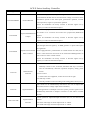
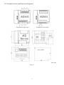
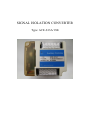
SIGNAL ISOLATION CONVERTER
Type: ACE-S13A/13B
1
ACE-S Series Auxiliary Controller
Type
Name
Purpose
The variation angle, tension, weight and angle bias on two axes detected by
synchronization machine can be converted as DC voltage; a converter can be
ACE-S02/02B/02C
Position Detector
controlled to operate at the same speed, synchronous operation, constant
tension operation, single-to-synchronous operation.
Built-in tilt mechanism can slowly increase or decrease signals set by
frequency to reduce the mechanical impact.
Can select as a proportional/differential controller. One proportional coupler
ACE-S04/06
Proportional/Differential
Coupler
can connect to six converters and control five proportional (differential)
couplers.
Built-in tilt mechanism can slowly increase or decrease signals set by
frequency to reduce the mechanical impact.
The rotational speed of a motor can be converted as converter frequency
input through electrical signal by an RPM generator or photo-interception
pulse generator.
ACE-S08/09
Speed Converter/Feed
Can be equipped with a potentiometer as constant tension for cloth, line or
Back Controller
plastics. Linear and loose conversion can be used with an RPM generator as
linear control or motor constant control.
Built-in tilt mechanism can slowly increase or decrease signals set by
frequency to reduce the mechanical impact.
Remote control:
Remotely control to start, accelerate, decelerate and stop a converter,
and can automatically memorize operation frequency during power
ACE-S10
Multi-function
failure.
Controller
Traverse control:
Used for transverse equipment, so that can move left or right.
PLC multi-step control:
Execute procedure control according to the setting phase, and recycle it.
Input current can be simultaneously delivered to five sets of output after
converted (Current or voltage output can be switched.).
ACE-S12
Signal Distributor
For the applications of multiple conversion system, pressure signals can be
simultaneously delivered to multiple converters so that achieve constant
pressure.
Used at a place for output and input conversion (I-I, I-V, V-V and V-I) or
ACE-S13A/13B
Signal Isolation
Converter
isolation.
ACE-S13A: The range of current output is DC 0 ~ 20mA.
ACE-S13B: The range of current output is DC 4 ~ 20mA.
2
Introduction
Thank you for purchasing ACE-S13 controller. Please carefully read this user manual before the
installation. In order to correctly operate and use, please attach this user manual on that machine so that
can provide the reference of maintenance and service or troubleshooting in the future.
Safety Notices
Please carefully read this user manual and pay attention to safety notices, symbols or text specified
in “DANGER” and “NOTE” prior to performing the installation, wiring, operation, maintenance or
troubleshooting.
DANGER: Indicates the operation could cause severe injury or death if it doesn’t execute according
to instruction on the user manual.
NOTE: Indicates the operation could minor injury or product damage if it doesn’t execute according
to instruction on the user manual.
※ Even though
indicates the level of light damage, it could cause severe injury.
Only qualified staff can carry out the installation, wiring, trial run or troubleshooting.
※Qualified staff: Those who get familiar with the principle, structure, characteristic, operation procedure
and installation of ACE controller to take safety measures and avoid danger as well as
carefully read the user manual.
3
Selected power voltage must have the specifications identical to controller input
voltage. If wrong voltage is connected, internal control circuit will be burned out.
Please pay special attention to that.
Wiring between ACE controller and converter should be as short as possible.
The length of output terminal “VO#(IO#) and GO#” and converter frequency
terminal “Vin (Iin) and Gnd” should be within 3m.
Please select appropriate line diameter when wiring main loop power.
Ground lines should conform to the third type (ground resistance below 100Ω).
Main loop power and control loop lines should be connected to ground point
(GRD).
Wiring and
Installation
Signal lines should adopt twisted pair or isolated lines to avoid noise interference,
and the ground items should be performed.
Signal lines should be kept away from high voltage or power lines. Don’t bundle
with high power lines.
Don’t connect control loop terminals during the power delivery to avoid damage
caused by the surge impact.
Please confirm power indicators on a panel turn off to perform the removal after the
power is disconnected.
Please connect according to terminal symbol when wiring, and lock screws to avoid
trip.
Please recover the upper cover to avoid electric shock after wiring is completed.
The wiring operations must be performed by the qualified staff.
Don’t install at a place where to have high temperature, humidity, oil, lint, iron
Ambient
Environment
powder, copper powder, dust and corrosion.
Heat dissipation should be considered when installing in a control panel. The
ambient temperature should not be greater than +50℃.
4
Contents
I. Features ------------------------------
1
II. Specifications ---------------------------
1
III. Terminal Definition -------------------------
1
IV. Terminal Position and Dimension Diagrams --------------
2
5
I. Features:
Two sets of signal isolation conversion circuit (output and input isolation) can invert V/V, V/I, I/V
and I/I, respectively.
II. Specifications:
Item
Power Voltage
Power Consumption
Input Signal
Output Signal
Operating Environment
Description
Remark
AC 90 ~ 260V, 50/60Hz
About 5VA
Voltage input: 0V ~ 10V
Current input: 0 ~ 20mA
Voltage output: 0V ~ 10V
Current output: ACE-S13A is 0 ~ 20 mA
ACE-S13B is 4 ~ 20 mA
Operating location: Installed at a place where no corrosive or
conductive gas, liquid and dust exists.
Ambient temperature: -10℃ ~ +50℃ (no condensation and
freeze)
Storage temperature: -20℃ ~ +60℃
Humidity: 90%RH
Vibration: Below 5.9m/sec(0.6G)
Altitude: Below 1000m (3280ft)
III. Terminal Definition:
Terminal Name
AC1 and AC2
GRD
P12
AI1-GI1
AI2-GI2
VO1-GO1
IO1-GO1
VO2-GO2
IO2-GO2
Description
Power input terminal
Input voltage AC 90 ~ 260V, 50/60Hz
Ground terminal for equipment
Power output terminal for potentiometer
DC 12V, 20mA(Max)
First analog input terminal
Voltage input (JP1short-circuit pin is moved to “V”.):
DC 0V ~ 10V input, input impedance 20kΩ
Current input (JP1short-circuit pin is moved to “I”.):
DC 0 ~ 20mA input, input impedance 250Ω
Second analog input terminal
Voltage input (JP2short-circuit pin is moved to “V”.):
DC 0V ~ 10V input, input impedance 20kΩ
Current input (JP2 short-circuit pin is moved to “I”.):
DC 0 ~ 20mA input, input impedance 250Ω
First voltage signal output terminal
Output range: DC 0 ~ 10V
Output current ≦ 5mA (output load resistance needs ≧ 2kΩ)
First current signal output terminal
Output range: ACE-S13A is 0 ~ 20 mA.
ACE-S13B is 4 ~ 20 mA.
(output load resistance needs ≦ 500Ω)
Second voltage signal output terminal
Output range: DC 0 ~ 10V
Output current ≦ 5mA (Output load resistance needs ≧ 2kΩ)
Second current signal output terminal
Output range: ACE-S13A is 0 ~ 20 mA
ACE-S13B is 4 ~ 20 mA.
(Output load resistance needs ≦ 500Ω)
Note 1: Two defaults (AI1 and AI2) are set as voltage input.
1
Rema
rk
Note
1
Note
1
IV. Terminal Position and Dimension Diagrams:
Terminals at upper layer
Terminals at lower layer
Screw M4-2
Unit: mm
Fig. (1)
2