1
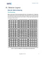
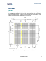
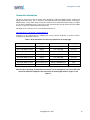
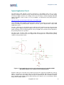
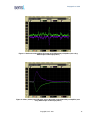
Array4p9
User Guide
Version 1.1
– March 2011
SensL Technologies Ltd.
6800 Airport Business Park
Cork, Ireland
www.SensL.com
Copyright SensL 2011
Array4p9 User Guide
Contents
I.
CONTACT ......................................................................................................................................................... 3
II.
INTRODUCTION ......................................................................................................................................... 3
ABOUT THIS DOCUMENT .......................................................................................................................................... 3
GETTING STARTED ................................................................................................................................................... 3
UNPACKING THE SYSTEM AND PREPARING FOR USE ................................................................................................ 3
SAFETY CONSIDERATIONS........................................................................................................................................ 3
SYSTEM CHARACTERISTICS AND SPECIFICATIONS ................................................................................................... 4
Dimensions .......................................................................................................................................................... 4
Weight .................................................................................................................................................................. 4
Power .................................................................................................................................................................. 4
Temperature ........................................................................................................................................................ 4
III.
OVERVIEW .................................................................................................................................................. 4
IV.
DETECTOR LAYOUT ................................................................................................................................. 5
DETECTOR OPTICAL INDEXING ................................................................................................................................ 5
Pixel Numbering .................................................................................................................................................. 5
Array4 Numbering ............................................................................................................................................... 6
DIMENSIONS ............................................................................................................................................................. 7
Top View .............................................................................................................................................................. 7
Bottom View ........................................................................................................................................................ 8
Side View ............................................................................................................................................................. 9
V.
ELECTRICAL GUIDELINES ................................................................................................................... 10
ARRAY4 CIRCUIT DIAGRAM................................................................................................................................... 10
INTERFACING ......................................................................................................................................................... 11
Connector Circuit Diagram............................................................................................................................... 11
Connector Information ...................................................................................................................................... 13
Temperature Monitor/Identification Chip ......................................................................................................... 14
Typical Application Circuit ............................................................................................................................... 15
VI.
REVISION CONTROL .............................................................................................................................. 17
Copyright SensL 2011
2
Array4p9 User Guide
I. Contact
For all enquiries email: [email protected]
II. Introduction
About this Document
This document provides the user with a comprehensive description of the Array4p9 detector. Optical,
electrical and mechanical features of the Array4p9 are described.
Getting Started
Please ensure that users have familiarized themselves with this user guide before using the Array4p9.
Unpacking the System and Preparing for Use
Contents of the package:
•
•
1 Array4p9 detector module (minimum)
Test data sheet
Unpack the contents and identify each of the components ensuring that ESD considerations are taken
into account when handling the Array4p9. It is recommended that rubber gloves are used when holding
the Array4p9 to avoid marking the optical surface which can be easily scratched if mishandled.
Often the product is used with optical grease for example to couple scintillator blocks to the detectors.
Care should be taking when cleaning the epoxy surface and it is recommended to use a clean lint free
cloth with ethanol to clean off the excess grease.
Safety Considerations
•
The system is not intended for outdoor use
•
Liquids should not be spilled on or into the system
Copyright SensL 2011
3
Array4p9 User Guide
System Characteristics and Specifications
Dimensions
48.0mm x 46.5mm x 9.5mm
Weight
26g
Power
Typically +30V bias – please refer to the test data sheet for recommended operating voltage
3V to 5V power for the temperature sensor
Temperature
Operating:
Storage:
0°C to +50°C
-20°C to +70°C
III. Overview
SensL’s Array4p9 is a modular detector array system. Building on SensL silicon photomultiplier (SPM)
technology, Array4p9 provides a fully solid-state, four-side scalable detector array. The detector contains
a 12 row by 12 column array of 3mm SPM detectors and each of these detectors can be individually
read out from a pair of board to board connectors on the rear side of the detector.
One application of the Array4p9 is a low light imaging detector for the readout of scintillator matrices in
Positron Emission Tomography (PET) scanners. Employing SPM technology, the Array4p9 detector
head requires low power and operating voltage, is compact, highly robust and offers excellent spatial
segmentation and photo response uniformity. Addressing high resolution imagers such as small animal,
pre-clinical and mammography PET, Array4p9 is a compelling alternative to multi-anode PMTs. A high
degree of modularity and compliance with the OpenPET standard makes Matrix9 a cost effective
substitute for PMTs in full-body PET systems.
The detector head contains detectors and readout connectors only and there is no pre-amplification
circuitry on the detector itself. This allows the customer flexibility to design their custom readout system.
There are numerous possibilities from the readout scheme including individual pixel readout, cross wired
readout and summed readout.
The Array4p9 system architecture is modular and is manufactured using SensL’s Array4 package. The
Array4 is a ceramic package that houses a 4 x 4 array of 3mm SPM devices. The package is of 20 way
pin grid array (PGA) type with each anode contact of the SPMs in the array available on separate pins.
The package is designed for common positive high voltage bias supplied to the 4 remaining pins. The
Array4p9 uses a 3 x 3 array of Array4 packages to produce a 12 by 12 array of 3mm SPMs. The
detector is designed so that it can be tiled on all 4 sides with little dead space enabling very large area
detectors to be manufactured.
On the back side of the detector there are two 80 way board to board connectors. All of the SPM anode
contacts are individually routed to the Array4p9 and there are 9 bias connections for each 4 x 4 block of
SPMs in the Array4p9 packages.
The Array4p9 also has a temperature sensor and serial identification chip in the center of the package
which allows the temperature to be continuously digitally monitored.
Copyright SensL 2011
4
Array4p9 User Guide
IV. Detector Layout
Detector Optical Indexing
Pixel Numbering
Figure 1 shows how the detectors are referenced with respect to their positions in the Array4p9 when
viewed from the topside. The nine Array4p9 packages can be seen arranged in the 3 x 3 format. The
correct orientation of the detector array can be viewed by ensuring that the +HV rectangular bond pads
form columns to the left hand side of each Array4 package. The SPMs are numbered consecutively with
respect to the Array4 package that they in and are referred to as PIXEL_IN[0] to PIXEL_IN[143] in the
circuit diagrams of this document.
Figure 1: Layout of the SPM pixels on the Array4p9 package (topside view)
Copyright SensL 2011
5
Array4p9 User Guide
Array4 Numbering
Figure 2 shows the indexing of the Array4 packages ARRAY[0] to ARRAY[8], each of the Array4
packages having their own +HV bias connection labeled ARRAY_IN[0] to ARRAY_IN[8] in the circuit
diagrams in the following sections.
Figure 2: Indexing for each of the Array4 packages in the Array4p9 (topside view)
Copyright SensL 2011
6
Array4p9 User Guide
Dimensions
Top View
The dimensions of the Array4p9 as viewed from the top side of the array are shown in Figure 3. The
Array4 packages are 16.0mm apart in the horizontal direction and 15.5mm apart in the vertical direction.
The overall dimension of 47.81mm x 46.31mm is actually defined by the extents of the Array4 packages
and not the carrier PCB underneath. This allows the Array4p9 modules to be seamlessly tiled on a pitch
of 48.0mm in the horizontal direction and 46.5mm in the vertical direction.
Figure 3: Dimensions of the Array4p9 as viewed from the detector side
Copyright SensL 2011
7
Array4p9 User Guide
Bottom View
The circuit board onto which the Array4 packages are mounted is viewed from the bottom or connector
side in Figure 4 and it has dimensions 46.5mm x 45.0mm x 1.6mm thickness. It can be seen that the
arrays overlap the PCB by just over 0.6mm.
In each corner of the PCB there are four PEM nut fasteners. These are internally threaded fasteners that
press fit into the PCB to allow the module to be mechanical fixed to a motherboard or equipment frame.
Care should be taken to avoid excessive loading on the PEMs and board to board connectors although
they should be suitable to mechanically support the load of an average scintillator block attached to the
detector array. The thread size for the PEMs is M2.5 for all four. The PEM on the top right is encircled
with silkscreen on the PCB to indicate the polarity of the array, the indicator marking the ARRAY_IN[0],
PIXEL_IN[0] corner.
Two 80 way board to board connectors J1 and J2 provide the electrical interface to the detector array
and the temperature sensor/serial ID chip. Their positions are also indicated on Figure 4.
Figure 4: Bottom side view of the Array4p9
Copyright SensL 2011
8
Array4p9 User Guide
Side View
A cross sectional side view of the Array4p9 is shown in Figure 5. The temperature sensor is mounted on
the top side of the detector carrier PCB directly behind the central Array4 to get as close to the detector
as possible. A metal spacer of thickness 2.0mm ensures that the Array4 packages are all mounted at
the same height. The PEM nuts are inserted from the top side of the detector PCB and any retraining
bolts inserted into the PEMs should not be screwed in more than 3mm to avoid the end of the bolt
putting pressure on the back of the Array4 packages.
The Array4p9 has two 80 way Hirose DF17 series connectors on its bottom side. The choice of
connector on the motherboard allows the distance from the bottom of the detector PCB to the top of the
motherboard PCB to be varied from 5.0mm to 6.0mm. Connector part numbers are given in the next
section on the electrical connections.
Figure 5: Cross sectional side view of the Array4p9
Copyright SensL 2011
9
Array4p9 User Guide
V. Electrical Guidelines
Array4 Circuit Diagram
A circuit diagram of one of the Array4 modules is shown in
Figure 6. This shows the connections for ARRAY[8] which can be seen from Figure 2 to be in the bottom
right hand corner of the Array4p9. Each of the nine Array4 packages have their own +HV bias voltage
connection and in this case the bias signal is labeled ARRAY_IN[8]. The bias connection is common for
all 16 SPMs in the Array4 package.
Each pixel of the array is a 3mm SPM device named PIXEL[0] to PIXEL[15] within each Array4. The
circuit shows that for ARRAY[8] the input connections to the pixels are labeled PIXEL_IN[128] to
PIXEL_IN[143] and these are connected to the p side of the SPMs. The exact positions of the pixels in
the Array4p9 can be obtained from Figure 1.
The bias is connected to the on chip quench resistors of SPM’s microcells which are on the n-terminal.
This polarity means that a positive bias must be applied to the ARRAY_IN[n] signals with respect to the
PIXEL_IN[m] connections.
Figure 6: Circuit diagram of one of the Array4 modules (ARRAY[8])
Copyright SensL 2011
10
Array4p9 User Guide
Interfacing
Connector Circuit Diagram
The connections for the 80 way DF17 series connector J1 are shown in Figure 7 and those for J2 are
shown in Figure 8. The connector locations and the polarization are denoted on the silkscreen on the
bottom layer of the PCB (Figure 4). Each PIXEL_IN and ARRAY_IN signal are available on single pins
with the exception of ARRAY_IN[4] which is available on both J1 and J2. The power supply pins for the
temperature/serial ID chip (VDD and GND) and the temperature/serial ID output are also available on
both J1 and J2. The reason for the repetition in these cases is that this allows the board to be plugged
into the motherboard either way around as a safety feature to prevent otherwise possible damage.
Figure 7: Circuit diagram for 80 way connector J1
Copyright SensL 2011
11
Array4p9 User Guide
Figure 8: Circuit diagram for 80 way connector J2
Copyright SensL 2011
12
Array4p9 User Guide
Connector Information
The type of connector used on the bottom of the Array4p9 is a DF17(2.0)-80DP-0.5V(57), 0.5mm pitch,
80way, 2mm high header. These connectors mate with either DF17(3.0)-80DS-0.5V(57) or DF17(4.0)80DS-0.5V(57) sockets which would need to be mounted on the motherboard 32mm apart (see Figure
4). The DF17(3.0)-80DS-0.5V(57) sockets give a 5mm board to board spacing and the DF17(4.0)-80DS0.5V(57) sockets give a 6mm board to board spacing.
Full details of the connector series can be obtained from Hirose:
http://www.hirose.co.jp/cataloge_hp/e68300022.pdf
Connectors for the motherboard are available from several common distributors as shown in Table 1
and other main distribution channels.
Table 1: Order information for connectors which mate to the Array4p9
Connector Part Number
Supplier
Order Number
Packaging
DF17(3.0)-80DS-0.5V(57)
Digikey
H11113TR-ND
Reel
DF17(3.0)-80DS-0.5V(57)
Digikey
H11113CT-ND
Cut Tape
DF17(3.0)-80DS-0.5V(57)
Digikey
H11113DKR-ND
Digi-Reel
DF17(4.0)-80DS-0.5V(57)
Digikey
H11120TR-ND
Reel
DF17(4.0)-80DS-0.5V(57)
Digikey
H11120CT-ND
Cut Tape
DF17(4.0)-80DS-0.5V(57)
Digikey
H11120DKR-ND
Digi-Reel
DF17(3.0)-80DS-0.5V(57)
Mouser Electronics
798-DF173080DS05V57
Reel
DF17(4.0)-80DS-0.5V(57)
Mouser Electronics
798-DF174080DS05V57
Reel
Note that when designing the motherboard to interface to the Array4p9 then the connections will
need to be mirrorred compared to the connections of the Array4p9 shown in Figure 7 and
Figure 8.
.
Copyright SensL 2011
13
Array4p9 User Guide
Temperature Monitor/Identification Chip
Each Array4p9 contains a temperature monitor directly behind the ARRAY[4] package. The is the
DS1822Z+ from Dallas Semiconductor/Maxim. The DS1822 digital thermometer provides 9- to 12-bit
centigrade temperature measurements and communicates over a 1-Wire bus that requires only one data
line for communication with a central microprocessor or FPGA. It has an operating temperature range of
–55°C to +125°C and is accurate to ±2.0°C over the range of –10°C to +85°C. Each DS1822 has a
unique 64-bit serial identification code, which will allow multiple Array4p9s to function on the 1-Wire bus
and be traced in a large scanning system.
The connections for the chip are shown in the table below:
Table 2: Signals and power supply for the DS1822Z+
Signal Name
VDD
GND
TEMP/SERID
Connector
J1
J2
J1
J2
J1
J2
Pin
Description
19
59
21
61
20
60
3.0V to 5.5V
0V
1 wire digital communication interface
Full details of how to communicate with the IC can be found on the manufacturer’s website:
http://pdfserv.maxim-ic.com/en/ds/DS1822.pdf
Figure 9: Circuit diagram for the DS1822Z+ temperature monitor and serial identification chip
Copyright SensL 2011
14
Array4p9 User Guide
Typical Application Circuit
The SPM pixels would typically be directly connected to a pre-amplifier circuit such as a transimpedance amplifier to convert the charge current produced by photon detections into a usable voltage
for analog to digital conversion. An example circuit is the fast charge sensitive integrating differential
output pre-amplifier shown in Figure 10. The pre-amplifiers are implemented using Analog Device’s
AD8132 chips:
http://www.analog.com/static/imported-files/data_sheets/AD8132.pdf
Use of differential output amplifiers allows the output signal to be transmitted over longer cable length
reducing sensitivity to ground potentials variations across the system compared with a single ended
amplification system.
The gain is defined by the 1K feedback resistor, while the 4.7pF feedback capacitor and 47ohm input
resistor suppress ringing and provide stability of the transient response. The 47 ohm output resistors
provide matching of the low output impedance of the pre-amplifier to the transmission line impedance,
thus providing reflection-free operation.
The value of the +HV bias signal is normally around 30V but may vary slightly between different
Array4p9 modules. Consult the test sheet shipped with the Array4p9 for the recommended operating
conditions of the particular module.
Figure 10: Typical application circuit for a pixel of the Array4p9 using the AD8132ARM
operational amplifier in fast charge sensitive integrating mode
Example oscilloscope screenshots of the signals observed on the output of the amplifier are shown in
Figure 11 and Figure 12. The signal shape (rise and fall time) is primarily defined by the internal SPM
RC time constant. At the gain settings shown in Figure 10 (defined by R1 and C1 feedback elements)
the pre-amplifier output saturates prior to SPM saturation on the output as it is assumed that the SPM is
being used in low light conditions.
Copyright SensL 2011
15
Array4p9 User Guide
Figure 11: Dark noise of the SPM on the output of the differential preamplifier (seen using
1Mohm/14pF oscilloscope probes)
Figure 12: Short (12nSec) blue LED pulse seen at the output of the differential pre-amplifier (seen
using 1Mohm/14pF oscilloscope probes)
Copyright SensL 2011
16
Array4p9 User Guide
VI. Revision Control
Rev. No
1
Date
17/02/2011
1.1
29/02/2011
Details of change(s)
Initial version
Edited based on feedback from D.Mcnally
28/02/2011
Copyright SensL 2011
Author(s)
S. Bellis
S. Bellis
17