1
Installation & Maintenance Data
IM 444-1
Group: Controls
Part Number: 573384Y
Date: February 1998
MicroTech®
Remote Monitoring and Control Panel
Applied Rooftop and Self-contained Air Conditioning Systems
For Use With McQuay Models RPS, RFS, RCS, RDT, RHS, RWS, RAH, SWP & SWT
a0177
© 1998 McQuay International
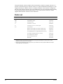
Contents
Contents................................................................................................................................................. 2
Illustrations............................................................................................................................................ 2
Tables .................................................................................................................................................... 3
Introduction ........................................................................................................................................... 4
General Description .............................................................................................................. 6
Component Data.................................................................................................................................... 6
Microprocessor Control Board .......................................................................................................... 7
Keypad/Display Board .................................................................................................................... 10
LED Status Board............................................................................................................................ 10
Software ID ......................................................................................................................................... 11
Software Compatibility.................................................................................................................... 12
MicroTech Monitoring and Networking Options ................................................................................ 13
PC Monitoring ................................................................................................................................. 13
Network Master Panel ..................................................................................................................... 13
Open Protocol.................................................................................................................................. 13
Installation............................................................................................................................ 15
Panel Location and Mounting.............................................................................................................. 15
Field Wiring ........................................................................................................................................ 16
Power............................................................................................................................................... 16
Network Communications ............................................................................................................... 16
PC Connection................................................................................................................................. 19
Network Commissioning ..................................................................................................................... 21
Addressing the Controllers .............................................................................................................. 21
Unit Controller Setup....................................................................................................................... 23
RMC Controller Setup..................................................................................................................... 23
Connecting the Communications Trunk .......................................................................................... 24
Service Information ............................................................................................................. 28
Wiring Diagram................................................................................................................................... 28
Test Procedures ................................................................................................................................... 29
Status LED Diagnostics................................................................................................................... 29
Troubleshooting Power Problems.................................................................................................... 29
Troubleshooting Communications Problems................................................................................... 30
Troubleshooting the LED Status Board........................................................................................... 30
Troubleshooting the Keypad/Display Board ................................................................................... 31
MCB Replacement .............................................................................................................................. 31
Parts List.............................................................................................................................................. 32
Illustrations
Figure 1. Control Panel Layout ............................................................................................................. 7
Figure 2. Microprocessor Control Board (MCB) .................................................................................. 7
Figure 3. Hex Switches.......................................................................................................................... 9
Figure 4. Keypad/Display Board (KDB) ............................................................................................. 10
Figure 5. LED Status Board (LSB)...................................................................................................... 10
Figure 6. Software ID Tag................................................................................................................... 12
Figure 7. RMC Panel Dimensions ....................................................................................................... 15
Figure 8. Typical Field Wiring Schematic........................................................................................... 18
Figure 9. RS-232 Cable Pinouts for 9-Pin Serial Ports........................................................................ 20
Figure 10. RS-232 Cable Pinouts for 25-Pin Serial Ports.................................................................... 20
Figure 11. AMP Connector Terminal Configuration........................................................................... 26
Figure 12. RMC Panel Schematic Legend........................................................................................... 28
Figure 13. RMC Panel Schematic....................................................................................................... 28
Figure 14. MCB Power Supply Terminals .......................................................................................... 30
2
IM 444-1
Tables
Table 1. MicroTech Unit Controller Installation Literature...................................................................4
Table 2. MicroTech Unit Controller Operation Literature ....................................................................4
Table 3. Model-Specific Unit Installation Literature.............................................................................4
Table 4. Green and Red Status LED Indication.....................................................................................8
Table 5. Amber Status LED Indication..................................................................................................8
Table 6. Program Code RMC-E01A Software Compatibility ............................................................12
Table 7. PC Specification ....................................................................................................................14
Table 8. RMC Panel Environmental Specifications ............................................................................15
Table 9. Network Communications Field Wiring Terminals...............................................................25
Table 10. Port B Voltages (AMP Type) ..............................................................................................25
McQuay, MicroTech, and RoofPak are registered trademarks of McQuay International.
Monitor and Open Protocol are trademarks of McQuay International.
Microsoft and MS-DOS are registered trademarks of Microsoft Corporation.
Windows is a trademark of Microsoft Corporation.
IBM is a registered trademark of International Business Machines Corporation.
©1998 McQuay International. All rights reserved throughout the world.
IM 444-1
3
Introduction
This manual provides information about the MicroTech Remote Monitoring and Control (RMC)
Panel for McQuay RoofPak applied rooftop systems and McQuay self-contained air conditioning
(SCAC) systems. It describes the RMC Panel’s components, field wiring requirements, network
commissioning procedures, and service procedures.
Table 1. MicroTech Unit Controller Installation Literature
Unit Type
Installation & Maintenance Data Bulletin Number
Applied Rooftop
IM 483
SCAC
IM 608
Table 2. MicroTech Unit Controller Operation Literature
Unit Type
Unit Control Configuration
Operation Manual Bulletin
Number
Applied Rooftop
Variable Air Volume
OM 108
Constant Air Volume, Zone Temperature Control
OM 109
Constant Air Volume, Discharge Temperature Control
OM 110
Variable Air Volume & Constant Air Volume, Discharge
Temperature Control
OM 123
Constant Air Volume, Zone Temperature Control
OM 124
SCAC
For a description of operation and information on using and programming the MicroTech RMC
Panel, refer to Bulletin No. OM 121, MicroTech Remote Monitoring and Control Panel. For specific
information about the MicroTech unit controllers, refer to the appropriate MicroTech unit controller
installation or operation manual (see Tables 1 and 2). For installation and commissioning instructions
and general information on a particular unit, refer to its model-specific installation manual (see Table
3).
Table 3. Model-Specific Unit Installation Literature
Unit Model
Installation & Maintenance Data Bulletin Number
RPS (45–135 Tons)RFS (45–135 Tons)RCS (45–135 Tons)
IM 485
RDT
IM 486
RAH
IM 487
RPS (18–40 Tons)RFS (18–40 Tons)RCS (18–40
Tons)RWSRHS
IM 157
SWP
IM 550
SWT
IM 623
!
WARNING
Electric shock hazard. Can cause personal injury or equipment damage.
This equipment must be properly grounded. Connections and service to the MicroTech control
panel must be performed only by personnel that are knowledgeable in the operation of the
equipment being controlled.
4
IM 444-1
!
CAUTION
Static sensitive components. A static discharge while handling electronic circuit boards
can cause damage to the components.
Discharge any static electrical charge by touching the bare metal inside the control panel
before performing any service work. Never unplug any cables, circuit board terminal blocks, or
power plugs while power is applied to the panel.
!
CAUTION
Unit isolation dampers required. Can cause improper system operation.
VAV units connected to a common supply duct must be isolated from the system with isolation
dampers when their fans are off. If this is not done, air can flow back through a disabled unit,
reducing duct pressure and potentially reducing or increasing the supply air temperature
enough to cause operational units to shut down.
NOTICE
This equipment generates, uses and can radiate radio frequency energy and, if not installed
and used in accordance with this instruction manual, may cause interference to radio
communications. It has been tested and found to comply with the limits for a Class A digital
device, pursuant to part 15 of the FCC rules. These limits are designed to provide reasonable
protection against harmful interference when the equipment is operated in a commercial
environment. Operation of this equipment in a residential area is likely to cause harmful
interference in which case the user will be required to correct the interference at his or her own
expense. McQuay International disclaims any liability resulting from any interference or
for the correction thereof.
IM 444-1
5
General Description
The MicroTech Remote Monitoring and Control (RMC) Panel is a microprocessor-based controller
designed to provide remote monitoring and multiple-unit control for up to eight MicroTech-equipped
applied rooftop or self-contained air conditioning (SCAC) units via network communications. The
RMC Panel’s multiple-unit control capabilities include common duct static pressure control and
common Control Temperature distribution for groups of two to eight units. (The Control Temperature
can be either space or return temperature.) The RMC Panel also includes four schedules, which can
be individually assigned to any single unit or combination of units.
A 12-key keypad and a 2-line by 16-character display give you access to the RMC controller’s status
information, setpoints, control parameters, alarm messages, and schedules. With a special keystroke
combination, the RMC Panel’s keypad/display can emulate any unit’s keypad/ display. The controller
includes password protection to protect against unauthorized or accidental setpoint or parameter
changes.
The RMC Panel and its associated units can operate together in a complete, “stand-alone” network, or
they can be incorporated into a larger network that includes a MicroTech Network Master Panel
(NMP) and other MicroTech controllers. In either case, an IBM compatible computer containing
MicroTech Monitor™ software can be connected to give you full-screen monitoring and control
capability. The computer can be connected directly or remotely via telephone lines with an optional
modem.
Note: As used throughout this manual, the term “RMC network” denotes the RMC Panel and its
associated applied rooftop or SCAC units; it would not include, for example, a MicroTech-equipped
reciprocating chiller that is on the same MicroTech network. Therefore, an “RMC network” could be
either a self-contained network (typical) or a part of a larger MicroTech network.
Component Data
The control panel layout for the RMC Panel is shown in Figure 1. The main components of the
system are the Microprocessor Control Board (MCB), the Keypad/Display Board (KDB), and the
LED Status Board (LSB). These components are mounted inside a standard NEMA 1 enclosure and
interconnected by ribbon cables, shielded multi-conductor cables, or discrete wiring. Power for the
system is provided by transformers T1 and T2.
6
IM 444-1
Figure 1. Control Panel Layout
MicroTech
Communications
Gateway
MicroTech
Microprocessor Control Board
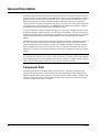
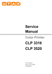
The Microprocessor Control Board (MCB) is shown in Figure 2. It contains a microprocessor that is
preprogrammed with the software required to monitor and control up to eight units. The MCB
coordinates all communications between the RMC controller and the unit controllers. The various
MCB connections and components are described below.
HI
LO
Hex switches
ADDRESS
FUSE 1
2
3
4
PORT A PORT B
COMMUNICATIONS
[FUSE: BUSSMAN MCR-1/4]
RUNNING
RESET
ACTIVE
DIGITAL INPUTS
KEYPAD/LCD DISPLAY
Figure 2. Microprocessor Control Board (MCB)
CPU
STATUS
OUTPUT 0
POWER IN
[18-24 VCT]
AC AC GND GND
DIGITAL OUTPUTS
ANALOG INPUTS
Microprocessor status LEDs
POWER FUSES
[BUSSMAN GDC-T2A]
AUX/OUT
IM 444-1
7
Digital Outputs Connection
After processing all network data, the MCB sends the appropriate output signals to the LED Status
Board through the Digital Outputs port via a plug-in ribbon cable.
Aux/Out Terminal Strip
The Aux/Out terminal strip provides 12 Vdc power to the LED Status Board and 5 Vdc power to the
back light on the Keypad/Display Board. Refer to the panel’s wiring diagram or Figure 13 for more
information.
Power In Terminal Strip
The MCB receives 18 Vac, center-tapped power from transformer T2 through the Power In terminal
strip. This power drives all logic and communications circuitry, the Aux/Out terminal strip, the LED
Status Board, and the Keypad/Display Board. Refer to the panel’s wiring diagram or Figure 13 for
more information.
Power Fuses
Two identical 2-amp fuses are located to the right of the Power In terminal strip. These fuses are in
the MCB power supply circuit.
Microprocessor Status LEDs
The green, red, and amber LEDs on the MCB provide information about the operating status of the
microprocessor. The amber LED also indicates the existence of alarm conditions in the RMC
network. (The Alarm LED on the LSB board also does this.)
Following is the normal start-up sequence that the three status LEDs should follow when power is
applied to the MCB:
1. The red (“Reset”) LED turns on and remains on for approximately 5 seconds. During this period
the MCB performs a self-test.
2. The red LED turns off and the green (“Running”) LED turns on. This indicates that the
microprocessor has passed the self-test and is functioning properly.
3. The amber (“Active”) LED remains off continually if no alarm conditions exist in the RMC
network. If alarm conditions exist, the amber LED will flash as shown in Table 5.
If the above sequence does not occur after power is applied to the controller, there is a problem with
the MCB or its power supply. For more information, refer to the “Test Procedures” section of this
manual, which is under “Service Information.”
Tables 4 and 5 summarize the green, red, and amber status LED indications.
Table 4. Green and Red Status LED Indication
Green LED State
Red LED State
Indication
Off
Off
No power to MCB
Off
On*
Self-test failure or power supply
problem
On
Off
MCB operating normally
* For longer than 5 seconds.
Table 5. Amber Status LED Indication
8
Amber LED State
Indication
Off
Normal operation
On 1/2 second; Off 1/2 second
Alarm condition
IM 444-1
Keypad/LCD Display Connection
The MCB receives input commands and operating parameters from the keypad and sends requested
information to the display through the Keypad/LCD Display port via a plug-in ribbon cable.
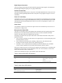
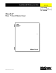
Hex Switches
The MCB includes two hex (hexadecimal) switches that are used to set the RMC controller’s network
address.
Figure 3. Hex Switches
The HI and LO hex switches are shown in Figure 3. A “hex switch setting” is defined as the HI switch
digit followed by the LO switch digit. For example, a hex switch setting of 2F would have the HI
switch set to “2” and the LO switch set to “F.” Typically, the RMC controller’s hex switch setting
should be 00. Refer to “Addressing the Controllers” in the “Network Commissioning” section of this
manual for more information.
Note: You can change the setting of a hex switch with a slotted-blade screwdriver that has a 3/32- inch
tip. If a hex switch setting is changed, power to the MCB must be cycled in order to enter the new
setting into memory. This can be done by opening and then closing the push button circuit breaker
(CB1) in the panel.
Communication Ports
The MCB has two communication ports: port A and port B. Each port has six terminals and is set up
for both the RS-232C and RS-485 data transmission interface standards. The male and female
connectors for these ports are manufactured by AMP. Therefore, they are referred to as “AMP plugs”
or “AMP connectors” throughout this manual. Socketed fuses located next to the ports protect the
communications drivers from voltage in excess of ±12 V. Following are brief descriptions of each
port’s function.
IM 444-1
Port A:
Port A is for communications with an IBM compatible PC using the RS-232C interface
standard. The PC can be directly connected, over a limited distance, with a twisted,
shielded pair cable, or it can be remotely connected via phone lines with a modem. (Port
A can also be used to connect a licensed building automation system to the MicroTech
network via Open Protocol.) The default communications rate is 9600 bps. For more
information, see “PC Connection” in the “Field Wiring” section of this manual.
Port B:
Port B is for MicroTech network communications using the RS-485 interface standard. A
twisted, shielded pair cable should be connected to port B via terminals B+, B–, and GND
on terminal block TB2. The communications rate is 9600 bps. For more information, see
“Network Communications” in the “Field Wiring” section of this manual.
9
Keypad/Display Board
The Keypad/Display Board (KDB) gives you a local interface with the RMC controller and a remote
interface with the unit controllers. All operating conditions, system alarms, control parameters, and
schedules can be monitored from the display. If the password has been entered, any adjustable
parameter or schedule can be modified with the keypad. Because the display is backlit, the liquidcrystal characters are highly visible regardless of the ambient light level. You can adjust the display
contrast with a small pot located on the back of the board (see Figure 1). For information on using the
keypad/display, refer to the “Getting Started” portion of Bulletin No. OM 121, MicroTech Remote
Monitoring and Control Panel.
Figure 4. Keypad/Display Board (KDB)
1.RMC Status
Schedule#1= Occ
CATEGORY
STATUS
CONTROL
MENU
ITEM
ACTION
PREV.
PREV.
INCR.
NEXT
NEXT
DECR.
ALARMS
CLEAR
SWITCH
ENTER
a0173
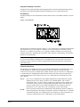
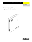
LED Status Board
The LED Status Board (LSB), which includes 10 LEDs and an alarm horn, shows you at a glance
which controller the keypad/display is interfaced with and whether any alarms exist in the network. It
is shown in Figure 5.
Figure 5. LED Status Board (LSB)
UNIT SELECTION
AND ALARM STATUS
UNIT #1
UNIT #5
UNIT #2
UNIT #6
UNIT 3#
UNIT #7
UNIT #4
UNIT #8
RMC PANEL
ALARM
a0174
10
IM 444-1
Unit Selection Indicators
Nine Unit Selection LEDs clearly indicate which controller in the network the RMC Panel’s
keypad/display is interfaced with. For example, if the “Unit #1” Unit Selection LED is lit, the RMC
Panel’s keypad/display will act exactly as if it were the keypad/display at Unit #1. A special
combination of keystrokes allow you to change controllers.
Alarm Status Indicator
The red “Alarm” LED blinks whenever there is an alarm in the RMC Panel or any of its associated
units. This occurs regardless of the current unit selection.
Alarm Horn
If it is enabled, the piezo alarm annunciator (alarm horn) sounds whenever an alarm occurs in the
RMC Panel or any of its associated units. This occurs regardless of the current unit selection. To
silence the alarm horn, press the ALARMS key while the RMC Panel is the selected controller. You can
adjust the alarm horn’s volume with a small pot located on the LSB board. You can also set up the
horn so that it sounds only when certain types of alarms occur (comm loss, faults, problems, or
warnings). For more information, refer to the “Alarm Monitoring” section of Bulletin No. OM 121,
MicroTech Remote Monitoring and Control Panel.
Note: Silencing the alarm horn does not clear an alarm. To clear an alarm from the RMC Panel you
must first select the unit with the alarm and then clear it. For more information, refer to the “Alarm
Monitoring” section of Bulletin No. OM 121.
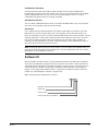
Software ID
MicroTech RMC controller software is factory installed and tested in each panel prior to shipment.
The software is identified by a program code (also referred to as the “Ident”), which is printed on a
small label affixed to the MCB. An example of this label is shown in Figure 6. The program code is
also encoded in the controller’s memory and is available for display on menu 16 of the keypad/
display or a PC equipped with Monitor software. Using menu 16 or Monitor software is the most
reliable way of determining the controller’s program code.
RMC controller program codification is as follows:
RMC-E01A
RMC Panel
English Units
Version (numeric)
Version revision (zero then alphabetic)
a0175
IM 444-1
11
Figure 6. Software ID Tag
P/N 860-654873B-06-0
SOFTWARE I.D.
EOS NO.
VENDOR S/N
VENDOR MDL#
DATE CODE
RMC-E01A
20.21
4839
250-06
12-94
MCB part number
Program code (“Ident”)
Software Compatibility
This edition documents revision A of the standard RMC software (RMC-E01A) and all subsequent
revisions of version 01 until otherwise indicated. If your software has a later revision code (for
example, RMC-E01B), some of the information in this manual may not apply to your software.
However, since revisions are minor software changes, the differences should be insignificant.
In its default configuration, this software is not compatible with some earlier versions of MicroTech
applied rooftop and SCAC controller software. The current software compatibility for the default
configuration is summarized in Table 6. The wildcard character (>) can be any letter.
If you want to use an RMC Panel with older units that have incompatible software, the unit controller
software must be upgraded. However, there is one exception: If the units are older applied rooftop
units that have incompatible software and they do not need the RMC Panel’s common duct static
pressure control feature, you can either (1) upgrade the unit controller software or (2) set the RMC
controller’s Configuration parameter to “ALL RTU.”
Note: When the Configuration parameter is set to “ALL RTU,” the RMC controller’s software
becomes compatible with all applied rooftop software and incompatible with all SCAC software. For
more information, refer to the “RMC and Unit Controller Setup” section of Bulletin No. OM 121,
MicroTech Remote Monitoring and Control Panel.
If you have a version of applied rooftop or SCAC software that is later than the compatible programs
shown in Table 6, it is likely that program RMC-E01A is compatible with it; however, it may not be.
To find out for sure, contact McQuayService.
Table 6. Program Code RMC-E01A Software Compatibility
Unit Application
Unit Type
Compatible Programs
Incompatible Programs
VAV, using the RMC
Panel’s common duct static
pressure control feature
Applied Rooftop
950164-040
950164 03 > and earlier
950314-020
950314-01 >
950162-040
950162-03 > and earlier
950313-020
950313-01 >
SCAC
950600-02C
950600-02B and earlier
Applied Rooftop
950164-03J to -03K950164040
{950164 03I and earlier
950314-01G to 01H950314-020
{950314 01F and earlier
950162-03J to -03K950162040
{950162 03I and earlier
950313-01F to -01G950313020
{950313 01E and earlier
VAV, not using the RMC
Panel’s common duct static
pressure control feature;
CAV, all applications
12
IM 444-1
Unit Application
Unit Type
SCAC
Compatible Programs
Incompatible Programs
950163-03H to -03J950163040
{950163 03G and earlier
950315-01E to -01F950315020
{950315 01D and earlier
950166-03G to 03H950166-040
{950166 03F and earlier
950316-01E to -01F950316020
{950316 01D and earlier
950600-020 to -02C
950600 01 >
Notes:
1. These applied rooftop programs can be made compatible with RMC-E01A by setting the RMC Panel’s Configuration parameter to
“ALL RTU.”
MicroTech Monitoring and Networking Options
PC Monitoring
A PC (personal computer) equipped with the appropriate Monitor software can be used to provide a
high-level interface with a MicroTech network (see PC specification below). Monitor software
features a Windows™-based display, multilevel password access, and advanced trend-logging. The
PC can be connected to the RMC controller either directly, via a single twisted, shielded pair cable, or
remotely, via phone lines with an optional modem. For more information on connecting the PC to the
controller, refer to “PC Connection” in the “Field Wiring” section of this manual.
For the most convenience and best operation, the PC should be considered dedicated to the
MicroTech system. However, you can exit the Monitor program to perform other tasks without
affecting equipment control. Refer to the Monitor user’s manual for additional information.
PC Specification
A direct or remotely connected computer can be used for monitoring RMC Panel and unit operation,
changing setpoints, scheduling, trend logging, downloading software, and diagnostics. The PC must
be an IBM or 100% true compatible. Table 7 shows the preferred and minimum PC specifications.
Network Master Panel
The MicroTech Network Master Panel (NMP) incorporates the RMC controller and its associated
units into a building-wide network with other MicroTech unit and auxiliary controllers. With a PC
and Monitor software, it gives the building operator the capability to perform advanced equipment
control and monitoring from a central or remote location. The following features are provided by the
optional NMP: (For further information, contact your McQuay sales representative.)
•
Remote unit monitoring
•
Advanced scheduling features
•
Advanced alarm management
•
Global operator override by unit type
•
Demand metering
•
Historical electrical data logging
Open Protocol
MicroTech Open Protocol™ provides an interface between the RMC Panel and the building
automation system of one of many participating manufacturers. With Open Protocol, the building
automation system can do the following:
IM 444-1
13
•
Monitor RMC schedule states, group Control Temperatures, group duct static pressures, and
group supply fan speed/vane position setpoints
•
Monitor most controller setpoints, parameters, and alarms
•
Set most controller setpoints and parameters
•
Set up multiple-unit control groups
In an Open Protocol application that includes an RMC Panel, the MicroTech Open Protocol Master
(OPM) Panel is not required because the RMC Panel performs its functions. For further information,
contact your McQuay sales representative.
Table 7. PC Specification
Preferred Configuration
Minimum Configuration
486DX processor, 66MHz or better
386SX processor, 16 MHz
8 MB of RAM or better
4 MB of RAM
120 MB hard disk drive or better
60 MB hard disk drive
3½” floppy disk drive
3½” floppy disk drive
Serial port (9 pin male; Com1 or Com2)
Serial port (9 or 25 pin male; Com1 or Com2)
Parallel port
–
Internal time clock, battery backed
Internal time clock, battery backed
Super VGA graphics capability
VGA graphics capability
Super VGA monitor
VGA monitor
Printer
–
Bus mouse or trackball
Serial mouse or trackball*
101 enhanced keyboard
101 enhanced keyboard
9600 bps modem, compatible with the AT command set
(optional)
1200 bps modem, compatible with the AT command set
(optional)
MS-DOS® 6.2 or higher
MS-DOS® 5.0
Microsoft® Windows™ 3.1 or higher
Microsoft® Windows™ 3.1
MicroTech® Monitor™ for Windows software
MicroTech® Monitor™ for Windows software
* If a serial pointing device is used, there must be another serial port (Com1 or Com2) available for connecting the PC to the
MicroTech controller.
14
IM 444-1
Installation
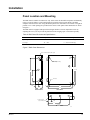
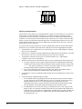
Panel Location and Mounting
The RMC Panel is suitable for indoor use only. Table 8 lists the allowable temperature and humidity
ranges. Locate the panel at a convenient height for operation of the keypad/ display, and allow
adequate clearance for the door swing. Mount the panel to the wall with screws or bolts. It weighs 40
pounds. Four 1/4 -inch openings are provided at the corners of the panel. Panel dimensions are shown
in Figure 7.
The RMC Panel is equipped with special door hinges that have a friction adjustment screw. By
adjusting this screw you can prevent the panel door from swinging open or closed unexpectedly.
Table 8. RMC Panel Environmental Specifications
Panel State
Temperature
Relative Humidity
Operating
32 – 100°F
0 – 95%(noncondensing)
In storage
–40 – 140°F
0 – 95%(noncondensing)
Figure 7. RMC Panel Dimensions
7/8" Dia knockouts (3 left, 3 right)
1/4" Dia moounting
slots (2)
14-1/2"
16-1/2"
14-3/4"
8-1/4"
1/4" Dia (2)
1-3/4"
1"
1-3/4"
12"
1"
4"
14"
Left Side View
Front View
2"
7/8" Dia knockouts
(3 top, 3 bottom)
1-7/8"
7"
12-1/8"
Bottom View
IM 444-1
a0176
15
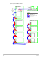
Field Wiring
Following are descriptions of the various field wiring requirements and options. All possible field
wiring connections are shown in Figure 8.
Note that the panel is divided into high and low voltage sections by a sheet metal barrier. The power
wiring should enter the high voltage section, and the communications wiring should enter the low
voltage section. Wiring penetrations must be made only through the 7/8 -inch knockouts provided.
The typical application includes either all applied rooftop units or all SCAC units; however, as shown
in Figure 8, the RMC Panel can monitor and control a mixture of these unit types.
Note: Wiring must comply with the National Electrical Code and all local codes and ordinances. The
warranty is void if the field wiring is not in accordance with these instructions.
Power
!
WARNING
Electric shock hazard. Can cause personal injury or death.
This equipment must be properly grounded.
All protective deadfront panels must be reinstalled and secured when power wiring is complete.
The RMC Panel requires a 115 Vac power supply, which should be connected to terminals L1 and L2
in the high voltage section of the panel. The panel must be properly grounded by connecting the
ground lug (GRD) to earth ground. Refer to Figure 8. Power wiring must be rated at 5 amps.
To gain access to the high voltage section, remove the deadfront barrier. It is attached to the panel
with two 5/16 -inch hex screws. Replace this deadfront when the wiring is complete.
The panel is internally protected with a 0.5-amp circuit breaker (CB1), which is located inside the
panel on the underside of the high voltage section (see Figure 1). This push-button circuit breaker can
also be used as an on-off switch for the panel. When the push button is in, the panel is on. When the
push button is out, the panel is off. A white ring on the switch shaft is visible when the push button is
out.
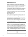
Network Communications
For network communications to occur, a twisted, shielded pair cable must be connected between the
RMC Panel, its associated units, and any other MicroTech unit or auxiliary controllers. This
interconnecting, “daisy-chain” wiring is shown in Figure 8. Network communications is accomplished
using the RS-485 interface standard at 9600 bps.
The typical network configuration, shown in Figure 8, consists of the RMC Panel and up to eight
applied rooftop or SCAC units. Unusual applications may include other MicroTech controllers; for
example, a Network Master Panel, Application Specific Controllers, or Unit Ventilator Controllers.
About MicroTech Network Architecture
All controllers in a MicroTech network are assigned a “level”: level 1, level 2, or level 3. All
networks must have one level-1 controller to coordinate communications. Multiple level-2 controllers
can be connected to the level-1 controller with a communications “trunk,” an isolated section of the
daisy-chained network wiring. (The network wiring between all controllers shown in Figure 8 is a
trunk.) Multiple level-3 controllers can be connected to a level-2 controller with a separate trunk. The
maximum allowable length of a communications trunk is 5000 feet.
16
IM 444-1
For the typical network in which there is one RMC Panel and no Network Master Panel, the RMC
Panel is the level-1 controller and its associated applied rooftop or SCAC units are level-2 controllers
(this is the default factory setup). If a Network Master Panel is included in the network, it is the level1 controller and the RMC Panel and its associated units are level-2 controllers. Unless there are many
water source heat pumps or unit ventilators in the network, there usually are not any level-3
controllers.
Cable Specification
The network communications cable must meet the following minimum requirements: twisted,
shielded pair with drain wire, 300 V, 60°C, 20 AWG, polyethylene insulated, with a PVC outer jacket
(Belden 8762 or equivalent). Some local codes or applications may require the use of plenum rated
cable. Do not install the cable in the same conduit with power wiring.
Note: Ideally, one continuous piece of cable should connect any two controllers. This reduces the
risk of communications errors. If the cable must be spliced, use crimp-type butt connectors (good) or
solder (best). Do not use wire nuts.
Wiring Instructions
Regardless of whether the RMC controller is level 1 or level 2, the network connection to the RMC
and unit controllers is at port B on their MCB boards. As shown in Figure 8, field wiring to port B on
these controllers can be accomplished by connecting the network cable to terminals B+, B–, and
GND in the RMC Panel; terminals 128, 129, and 130 in each rooftop unit panel; and terminals B+,
B–, and GND in each SCAC unit panel.
The unit designations shown in Figure 8 (“Unit #1” through “Unit #8”), are established by the
network address, not the physical position of the unit in the daisy chain. The networked controllers
can be wired in any order. For example, the RMC controller could be connected between Unit #1 and
Unit #2. It is highly recommended that the installing contractor keep track of the physical order of
the controllers on the daisy-chained trunk. This facilitates troubleshooting any network
communications problems that may occur. For more on the network address, see “Addressing the
Controllers” in the “Network Commissioning” section of this manual.
Use the following procedure to perform the network wiring:
1. Before beginning, verify that the port B plug is disconnected from every controller on the
communications trunk being wired. These plugs are connected during the commissioning
procedure. This is a precaution to prevent stray high voltage from damaging the controllers. Any
voltage in excess of 12 V can damage the board’s communications drivers.
2. Connect the network cable in a daisy-chain manner as shown in Figure 8. Use caution to assure
that the correct polarity is maintained at each controller. Be sure to connect each cable’s shield to
the controllers as shown in the figure. Like the positive (+) and negative (–) conductors, the
shield (ground) conductor must be continuous over the trunk.
3. If a Network Master Panel is included in the network, connect its B port to the trunk in a similar
fashion.
IM 444-1
17
Figure 8. Typical Field Wiring Schematic
RMC Panel
TB1
Hot
L1
Optional Monitor software package
Optional PC Communications Cable
Port A Port B
115 Volts AC
Power Supply
(Fused 15 Amps)
Neutral
Hardware
by others
MCB
L2
Legend
GRD
Factory wiring
Field wiring terminal
B+
Field wiring
B-
Twisted, shielded pair cable
with drain wire
GND
BLK
WHT
TB2
Unit #5(applied rooftop)
TB2
128
128
129
129
130
130
WHT
TB2
BLK
BLK
WHT
Unit #1(applied rooftop)
128
129
129
130
130
WHT
TB2
128
Unit #7(SCAC)
TB2
TS2
128
B+
B-
130
GND
WHT
129
BLK
BLK
WHT
Unit #3(applied rooftop)
Unit #4(applied rooftop)
Input Board
Unit #8(SCAC)
TB2
TS2
128
B+
129
B-
130
GND
WHT
BLK
18
Unit #6(applied rooftop)
TB2
BLK
BLK
WHT
Unit #2(applied rooftop)
Input Board
WHT
BLK
IM 444-1
PC Connection
Regardless of whether the PC is connected directly or remotely via phone lines, the connection to any
MicroTech controller is at port A on the MCB. It is best to connect a PC to the level-1 controller
because faster data transmission results; however, a PC can be connected to any level-2 controller that
does not have level-3 controllers associated with it. Either way, the PC has access to the entire
network (see note below). In the typical application, the RMC controller is level 1, the unit controllers
are level 2, and there are no level-3 controllers. See “Network Communications” above for more on
network architecture.
It is possible to connect two or more PCs to the network, but only one PC can be connected to any
one controller. The PC that is used most often should be connected to the level-1 controller for better
performance. For example, you may have one PC that you use at the building during the week and
another PC that you use at home on weekends. In this situation, you may want to connect the on-site
PC to the level-1 controller and the modem for the off-site PC to a level-2 controller.
The RMC controller’s default port A communications rate is 9600 bps; however, it can be changed.
For more information, see the “RMC and Unit Controller Setup” section in Bulletin No. OM 121,
MicroTech Remote Monitoring and Control Panel.
Note: If a PC is connected to a level-2 controller, a level-1 RMC Panel must be set up to poll that
level-2 controller so that the PC has access to the entire network. You can do this at the RMC
keypad/display by adjusting the Total Slaves parameter, which is located under menu 16, “Service.”
See the “RMC and Unit Controller Setup” section in Bulletin No. OM 121 for more information.
Direct Connection
An RS-232 communications cable kit that allows a PC to be directly connected to any MicroTech
controller is available from McQuay International. The part number is 0057186802. The cable has a
female DB-9 connector for connection to the PC’s 9-pin serial port. (If the PC has a 25-pin serial
port, obtain an adapter.) The cable length is 12 feet. If more length is required, a twisted, shielded
pair cable can be spliced into the kit cable (see “Cable Specification for Direct PC Connection”
below). If this is done, splice the conductors with crimp-type butt connectors (good) or solder (best).
Do not use wire nuts.
The maximum allowable cable length for direct connection between the PC and a controller is 50
feet. If the desired length is over 50 feet, the MicroTech RS-232 Cable Extension Kit is required. This
kit can extend the maximum allowable distance between the PC and the controller to 4000 feet. The
part number is 0065487001.
Remote Connection
A voice quality, direct-dial telephone line is required for remote or off-site PC access to the network.
The phone line should be terminated with a standard RJ-11 modular phone plug. A modem enables a
remote or off-site PC to communicate with the networked controllers via phone lines.
A modem is a standard unit option, but it is not an RMC Panel option. However, a modem that can be
field installed in the RMC Panel (or any unit) is available from McQuay International. The kit comes
complete with a 14,400 bps modem (set up for 9600 bps) and a wiring harness. If a remote PC
connection is required, it is recommended that the modem at the MicroTech controller be supplied by
McQuay International.
Installation and wiring instructions for the MicroTech Modem Kit are included in installation manual
for the modem.
IM 444-1
19
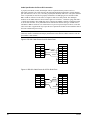
Cable Specification for Direct PC Connection
A properly terminated, twisted, shielded pair cable is required to directly connect a PC to a
MicroTech controller. The cable must meet the following minimum requirements: twisted, shielded
pair with drain wire, 300 V, 60°C, 20 AWG, polyethylene insulated, with a PVC outer jacket (Belden
8762 or equivalent). It must also be properly terminated to an AMP plug on one end and a female
DB-9 or DB-25 connector on the other. See Figures 9 and 10 for cable pinouts. The AMP part
numbers for the AMP connector shown in these figures are as follows: 1-480270-0 (plug) and 606171 (female pin terminals). This AMP plug can be connected to an RMC controller, an applied rooftop
or SCAC unit controller, or any other MicroTech controller that has the same type of AMP socket.
The DB-9 or DB-25 connector is for connection to a 9-pin or 25-pin serial port on the PC. Note that
some local codes or applications may require the use of plenum rated cable. Do not install the cable in
the same conduit with power wiring.
Note: A factory-assembled cable that meets this specification is part of the PC Communications
Cable Kit, which is available from McQuay International. This cable has a DB-9 connector. The kit
part number is 0057186802.
Figure 9. RS-232 Cable Pinouts for 9-Pin Serial Ports
AMP Plug
Signal
Female DB-9
Pin
TD
–
1
RD
3
GND
–
5
2
6
Pin
White
Black
Shield
Signal
1
DCD
2
RD
3
TD
4
DTR
5
GND
6
DSR
7
RTS
8
CTS
a0109
Figure 10. RS-232 Cable Pinouts for 25-Pin Serial Ports
AMP Plug
Signal Pin
TD
–
1
2
RD
GND
–
3
5
6
Black
White
Shield
Female DB-25
Pin
Signal
2
3
4
5
6
7
8
20
TD
RD
RTS
CTS
DSR
GND
DCD
DTR
a0110
20
IM 444-1
Network Commissioning
The purpose of network commissioning is to establish and verify communications between the RMC
Panel and its associated applied rooftop or SCAC units. (It is not to establish and verify unit
operation.) Network commissioning can be done independently of unit commissioning; however, if it
is done before the units are commissioned, care should be taken to assure that the units do not start.
The following instructions describe how to do this. To commission the network, you must be familiar
with the operation of the keypad/display. For information, see the “Getting Started” portion of
Bulletin No. OM 121, MicroTech Remote Monitoring and Control Panel.
Before any unit is allowed to operate, it must be commissioned in accordance with the instructions in
the MicroTech unit controller installation literature and the model-specific unit installation literature
(see Tables 1 and 3). In addition, the RMC Panel and its associated unit controllers must be set up so
that they work properly together. This setup, which can be done before or after the network is
commissioned, is described in Bulletin No. OM 121.
A PC is not required to commission networks that include only RMC Panel(s) and applied rooftop or
SCAC unit(s) because communications can be verified by using the RMC Panel’s keypad/display.
However, if you want to use a PC to verify network communications, you can. The PC must be
equipped with MicroTech Monitor software.
Addressing the Controllers
For network communications to occur, each controller in the network must have a unique network
address. A controller’s hex switch setting defines its network address. An applied rooftop or SCAC
controller’s hex switch setting also defines its unit designation, which is listed on the LED Status
Board; for example, “Unit #1.” For more on hex switch settings, see “Microprocessor Control Board”
in the “Component Data” section of this manual.
After changing a hex switch setting, power to the MCB must be cycled to set the new address into
memory. In the RMC Panel, you can do this by opening and then closing circuit breaker CB1. In the
unit controllers, you can do this by opening and then closing switch S1.
The hex switches are set differently depending on whether or not there is a Network Master Panel
(NMP) or more than one RMC Panel in the network. Following are instructions on how to set them.
Note: If a unit is running, you should shut it down before removing power from its controller. Do this
by changing its control mode to “Manual Off.”
The Typical Network
The typical network includes one RMC Panel and one to eight applied rooftop or SCAC units. It may
also include other level-2 unit or auxiliary controllers that could be accessed with a PC via network
communications. In this case, the RMC controller is the level-1 controller and the unit controllers are
level-2 controllers. Since the RMC Panel is level 1, its hex switch setting must be 00. The hex switch
settings of the level-2 controllers must start at 01 and continue consecutively to a maximum of 40
(decimal 64). There must be no gaps in the sequence and no duplicate settings. As long as these rules
are followed, a level-2 controller’s hex switches can be set to any value. To keep the system simple,
you should consider addressing the applied rooftop and SCAC units according to their designations.
For example, assume that a MicroTech network includes an RMC Panel, four rooftop units, and one
reciprocating chiller. One possible addressing scheme is as follows:
IM 444-1
Hex Switch Setting
Controller
00
RMC Panel
01
Unit #1
02
Unit #2
03
Unit #3
21
Hex Switch Setting
Controller
04
Unit #4
05
Reciprocating chiller (PC accessible only)
Note: If a PC or modem is connected to a level-2 controller, that controller should have as low an
address as possible. This improves the performance of network communications because it reduces
the required value of the RMC controller’s Total Slaves parameter and thus the amount of polling.
For example, if a modem is connected to Unit #3, you should consider setting Unit #3’s hex switches
to “01.” See the “RMC and Unit Controller Setup” section in Bulletin No. OM 121 for more
information.
Networks With an NMP
If an RMC Panel is included in a network that has an NMP, the NMP must be the level-1 controller.
In this case, an RMC Panel is a level-2 controller and the unit controllers are also level-2 controllers.
Since the NMP is level 1, its hex switch setting must be 00. The hex switch settings of the level-2
controllers must start at 01 and continue consecutively to a maximum of 40 (decimal 64). There must
be no gaps in the sequence and no duplicate settings. As long as these rules are followed, a level-2
controller’s hex switches can be set to any value. Two or more RMC Panels and multiple units are
possible in this type of network.
For example, assume that a MicroTech network includes an NMP, an RMC Panel, two rooftop units,
and one screw chiller. One possible addressing scheme is as follows:
Hex Switch Setting
Controller
00
NMP
01
RMC Panel
02
Screw chiller (PC accessible only)
03
Unit #1
04
Unit #2
Networks With Two or More RMC Panels and No NMP
If two or more RMC Panels are included in a network that does not include an NMP, one of the RMC
Panels must be the level-1 controller. In this case, the other RMC Panels are level-2 controllers and
the unit controllers are also level-2 controllers. The level-1 RMC Panel’s hex switch setting must be
00. The hex switch settings of the level-2 controllers must start at 01 and continue consecutively to a
maximum of 40 (decimal 64). There must be no gaps in the sequence and no duplicate settings. As
long as these rules are followed, a level-2 controller’s hex switches can be set to any value.
For example, assume that a MicroTech network includes two RMC Panels, and ten SCAC units. Each
RMC Panel will control and monitor five units. One possible addressing scheme is as follows:
22
Hex Switch Setting
Controller
00
RMC Panel “A”
01
RMC Panel “B”
02
Unit #1 for RMC Panel “A”
03
Unit #2 for RMC Panel “A”
04
Unit #3 for RMC Panel “A”
05
Unit #4 for RMC Panel “A”
06
Unit #5 for RMC Panel “A”
07
Unit #1 for RMC Panel “B”
IM 444-1
Hex Switch Setting
Controller
08
Unit #2 for RMC Panel “B”
09
Unit #3 for RMC Panel “B”
0A
Unit #4 for RMC Panel “B”
0B
Unit #5 for RMC Panel “B”
Note: The only advantage to creating a network like this is to allow a PC access to all networked
controllers. If there is no PC, each RMC Panel should be set up as a level-1 controller in a separate
network as described above in “The Typical Network.”
Note: If a PC or modem is connected to a level-2 controller, that controller should have as low an
address as possible. A level-2 RMC Panel should also have as low an address as possible. This
improves the performance of network communications because it reduces the required value of the
level-1 RMC controller’s Total Slaves parameter and thus the amount of polling. For example, if a
modem is connected to Unit #2 for RMC Panel “B” in the above example, you should consider
setting the hex switches for RMC Panel “B” to “01” and the hex switches for its Unit #2 to “02.” See
the “RMC and Unit Controller Setup” section in Bulletin No. OM 121 for more information.
Unit Controller Setup
The applied rooftop or SCAC unit controller setup that results by following these instructions is the
minimum required for commissioning the network. Further setup is likely necessary to adapt the unit
controllers to your particular application’s requirements. For complete information on how to do this,
see the “RMC and Unit Controller Setup” section in Bulletin No. OM 121.
Control Mode
If any units have not been commissioned, it is recommended that they be manually shut down during
this network commissioning process to ensure that they do not start when communications begin. One
way to manually shut down a unit is to set its control mode to “Manual Off.” At the unit controller’s
keypad/display, the control mode is the first item under menu 11, “Control Mode.” You can get to it
quickly by pressing the CONTROL key.
You can set the control modes for units that have been commissioned as desired during network
commissioning (see note below). The units can be either on or off. (If a unit is off, it must have
power.) Note that a unit that is off can start up when communications begin if an occupied RMC
schedule is assigned to it. A unit that is on cannot be shut down by the RMC Panel when
communications begin.
Note: If any units are part of a multiple-unit control group, you should consider keeping them
manually shut down until their controllers and the RMC controller are set up properly. This is a
precaution to ensure that simultaneous heating and cooling and erratic duct static pressure control
does not occur.
RMC Controller Setup
The RMC controller setup that results by following these instructions is the minimum required for
commissioning the network. Further setup is likely necessary to adapt the RMC controller to your
particular application’s requirements. For complete information on how to do this, see the “RMC and
Unit Controller Setup” section in Bulletin No. OM 121.
Number of Units
The RMC controller needs to know how many applied rooftop or SCAC units are connected to it.
You set this value at the keypad/display with the “Nmbr of Units=” item under menu 16, “Service.”
IM 444-1
23
Unit Address
The RMC controller needs to know the network addresses of its associated units. You set these values
at the keypad/display with the “Unit # > Addr=” items under menu 16, “Group Assign.” (The wildcard
character in the item name could be a number from 1 to 8.) The value of each of these parameters
must match the hex switch setting at the corresponding unit. For example, if the hex switch setting at
Unit #3 is 01, the “Unit #3 Addr=” item must be set to 01. If there are less than eight units associated
with the RMC, set the unused Unit # > Address parameters to “NA” (default).
Controller Level
The RMC controller needs to know whether it is a level-1 or level-2 controller. You set the level at
the keypad/display with the “Level=” item under menu 16, “Service” (default is level 1).
To change the controller level
1. Set the hex switches as required. A level-2 controller’s hex switch setting cannot be 00. A level-1
controller’s hex switch setting must be 00.
2. At the keypad/display, set the “Level=” item to “1” or “2” as required. When the ENTER key is
pressed, the RMC controller automatically corrects its checksums and reset itself. It also changes
the Total Slaves parameter to “0” (see below).
Total Slaves
A level-1 RMC controller needs to know how many level-2 controllers (slaves) it needs to poll.
(When a level-1 controller polls one of its level-2 slaves, it actively “asks” the slave if it has any
requests for information from other controllers.) The Total Slaves parameter defines this number.
You can set the Total Slaves parameter at the keypad/display with the “Total Slaves=” item under
menu 16, “Service” (default is 0). A level-2 RMC Panel’s Total Slaves parameter should always be
set to “0.”
In most cases, the Total Slaves parameter must be changed only if there is (1) a level-2 RMC Panel or
(2) a PC connected to a level-2 controller. In the typical network, which includes one RMC Panel
(level 1) and no PC, the Total Slaves parameter should be set to “0” (default).
If a level-2 controller needs to be polled, set the Total Slaves parameter just high enough to include
that controller. For example, assume there are nine level-2 controllers connected to a level-1 RMC
Panel; the controller at address 02 is another RMC Panel; and the controller at address 06 has a
modem connected to it. In this case, the Total Slaves parameter should be set to “6.”
Connecting the Communications Trunk
Use the following two procedures to connect the RMC controller and unit controllers to the network.
You must complete the first procedure before beginning the second.
Communications Cable and Port B Check
The network communications cable should have been installed in accordance with the instructions in
the “Field Wiring” section of this manual. This procedure verifies (1) that there are no shorts or stray
voltages anywhere in the communications trunk and (2) that port B in each controller is intact. It must
be performed once at every controller on the trunk before going on to the following “Verifying
Communications” procedure. You can start at any controller and proceed in any order.
Before beginning, verify that the port B connectors are disconnected from every controller on the
trunk. On the RMC, applied rooftop, and SCAC controllers, the port B connector is an AMP plug.
1. Verify that there is no voltage between any conductor and ground:
Use a voltmeter to test for voltage at the network communications field wiring terminal block.
With one lead on the control panel chassis (ground), check for voltage at the “+,” “–,” and
“ground” terminals. Table 9 summarizes the terminal labels for the various controllers. There
should be no AC or DC voltage.
If you get a 2 or 3 Vdc reading, it indicates that one or more powered controllers are connected
to the trunk. These controllers should be located and disconnected.
24
IM 444-1
Note: The first check should test for voltage throughout the entire trunk; however, it is important
that it be done at every controller. Cables look similar and can easily become crossed.
2.
Verify that there are no shorts between any two conductors:
Use an ohmmeter to test for shorts at the network communications field wiring terminal block.
For the three combinations of conductor pairs, there should be infinite resistance between the
conductors (see Table 9).
If you find a resistance that is high but less than infinite, it indicates that one or more nonpowered
controllers are connected to the trunk. These controllers should be located and disconnected.
Note: The first check should test for shorts throughout the entire trunk; however, it is important
that it be done at every controller. Breaks in the trunk may exist.
3.
4.
5.
6.
7.
Plug the network communications connector into the B port.
Verify that there is power to the MCB and then check for proper port B voltage levels:
Use a DC voltmeter to test for proper voltages at the network communications field wiring
terminal block. With one lead on the control panel chassis (ground), check the voltage at the “+,”
“–,” and “ground” terminals (see Table 9). The proper voltages are shown in Table 10. Note that
the port B terminal labels in Table 10 are for the AMP-type connectors used on the RMC,
applied rooftop, and SCAC controllers. Figure 11 shows the terminal configuration for this AMP
connector’s socket, which is mounted on the MCB board. (The terminals are labeled on both the
socket and the plug, but they’re hard to see.)
For communications to occur, each networked controller must have proper voltages at its port B
terminals. When there is only one controller connected to the trunk (as in this check), the
measured voltages are for port B on that controller.
If no voltage or improper voltages are found, check the wiring between the port terminals and the
field terminals. Using Table 10 and Figure 11, verify that the three conductors are properly
terminated in the AMP plug. Remove and check the two fuses above the B port. If there is still a
problem, it is likely that the communications driver in the MCB is defective.
Unplug the network communications connector from the B port.
Go to the next controller and repeat steps 1 through 5.
After finishing the last controller, do the following “Verifying Communications” procedure.
Table 9. Network Communications Field Wiring Terminals
Network Comm. Field Terminal
Controller
+
–
Ground
RMC Panel
TB2-B+
TB2-B–
TB2-GND
Applied Rooftop
TB2-128
TB2-129
TB2-130
SCAC
TS2-B+(Input Brd.)
TS2-B–(Input Brd.)
TS2-GND(Input Brd.)
Table 10. Port B Voltages (AMP Type)
Port B (RS-485)
IM 444-1
Signal
Terminal
Acceptable Voltage Reading
+
4
3.0 ± 0.3 Vdc
–
3
2.0 ± 0.3 Vdc
Ground
5
0.0 ± 0.2 Vdc
25
Figure 11. AMP Connector Terminal Configuration
FUSE 1
3
4
5
6
5
6
3
4
3
4
1
2
1
2
2
PORT A
PORT B
COMMUNICATIONS
[FUSE: BUSSMAN MCR-1/4]
a0114
Verifying Communications
This procedure verifies that proper communications have begun for each controller as it is connected
to the network. The procedure begins with the level-1 controller because it coordinates network
communications. After connecting it, you should connect any level-2 RMC Panels and then the unit
controllers. You can connect the unit controllers in any order; however, it is better to follow the daisychain as you proceed. This makes troubleshooting easier if communications problems occur. For the
typical network in which there is no Network Master Panel, the RMC Panel is the level-1 controller
and the units are level-2 controllers.
As a result of the previous procedure, the network communications connector are disconnected from
the B port at every controller on the trunk. Be sure that this is true before beginning this procedure.
1. Verify that the level-1 controller has a hex switch setting of 00. See “Addressing the Controllers”
above for more information.
2. Plug the level-1 controller’s network communications AMP connector into the B port. Verify that
there is power to the level-1 controller and then go to the first level-2 controller.
3. Verify that the controller has the correct level-2 network address. See “Addressing the
Controllers” above for more information.
4. With the controller’s B port disconnected, check for proper communications trunk voltage levels:
a. Use a DC voltmeter to test for proper voltages at the network communications field wiring
terminal block. With one lead on the control panel chassis (ground), check the voltage at the
“+,” “–,” and “ground” terminals (see Table 9). The proper voltages are shown in Table 10.
Note that voltage fluctuation within the acceptable range is normal.
b. If no voltage or improper voltage levels are found, verify that the level-1 RMC Panel or
NMP is energized and that the communications trunk wiring is intact.
5. Verify that there is power to the MCB and then plug the network communications connector into
the B port.
6. Verify that network communications have begun:
a. Go to the RMC Panel’s keypad/display and select the unit just connected. (If the controller
you just connected is a level-2 RMC Panel, go to step 7.) To do this, press the SWITCH key
and then quickly press the NEXT key in the Menu key group. Repeat this keystroke
combination as necessary to get the desired unit. The Unit Selection LED for the selected
unit will illuminate. The keypad/ display should show the unit controller’s data.
b. If communications do not exist, the message “Communications lost w/ unit” appears in the
display. In this case, check the terminations between the B port and the field terminal block
at the unit and, if no other units are communicating, its RMC Panel. If the unit controller just
connected is associated with a level-2 RMC Panel, make sure that this RMC Panel’s level
was changed from 1 to 2.
26
IM 444-1
Note: If the level-2 controller is not an RMC, applied rooftop, or SCAC unit controller, you
need a PC to verify communications. Refer to the user’s manual provided with the Monitor
software for more information.
7.
8.
IM 444-1
Go to the next controller and repeat steps 3 through 6.
If the units have been commissioned, set up the RMC and unit controllers as desired for normal
operation.
27
Service Information
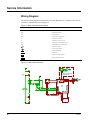
Wiring Diagram
The following wiring diagram is identical to the one in the RMC Panel. It is reproduced here for your
convenience. The legend is shown in Figure 12.
Figure 12. RMC Panel Schematic Legend
Component Designation
Description
CB1
Circuit Breaker
KDB
Keypad/Display Board
LSB
LED Status Board
MCB
Microprocessor Control Board
T1
Transformer: 115/24 Vac
T2
Transformer: 24 Vac/18 Vac-CT
TB1
Terminal Block: High Voltage Section
TB2
Terminal Block: Low Voltage Section
Factory Wire Number
Factory Wiring Terminal
Field Wiring Terminal
Field Wiring
Printed Circuit Board Terminal
Twisted, Shielded Pair Cable
Figure 13. RMC Panel Schematic
28
IM 444-1
Test Procedures
A listing of MicroTech related part numbers is included in the “Parts List” section of this manual. If
the MCB must be replaced, refer to the “MCB Replacement” section of this manual.
Status LED Diagnostics
The MCB status LED indications can aid in controller diagnostics. If the status LEDs do not operate
normally as described in the “Component Data” section of this manual (see Table 4), there is a
problem with the MCB. Following are troubleshooting procedures for the various symptoms.
Red LED Remains On
If the red LED remains on after the 5-second self-test period, it is likely that the MCB is defective.
However, this can also occur in some instances if there is a power supply problem. Refer to
“Troubleshooting Power Problems” below.
Red and Green LEDs Off
If the red and green LEDs do not turn on after power is applied to the controller, there is likely a
defective component or a problem in the controller’s power distribution circuits. Refer to
“Troubleshooting Power Problems” below.
Troubleshooting Power Problems
The MCB receives 18 Vac, center-tapped power from transformer T2. It then distributes both 5 Vdc
and 12 Vdc power to the various MicroTech components. A problem that exists in any of these
components can affect the MCB and thus the entire control system. Power problems can be caused by
a external short, which can blow a fuse, or a defective component, which can either blow a fuse or
create an excessive load on the power supply. An excessive load can lower the power supply voltages
to unacceptable levels. Use the following procedure to isolate the problem. Note that this procedure
may require two or three spare MCB fuses (see parts list). Refer to the panel wiring diagram or Figure
13 as you proceed.
Verify that circuit breaker CB1 is closed.
1. Remove the MCB Power In terminal strip connector and check for 9 Vac between the terminals
on the plug corresponding to terminals 2 and 3 on the board (see Figures 2 and 14). Then check
for 9 Vac between the terminals on the plug corresponding to terminals 1 and 3 on the board.
(Readings of 9–12 Vac are acceptable.)
a. If 9 Vac is present between both sets of terminals, go to step 3.
b. If 9 Vac is not present between both sets of terminals, check transformers T2 and T1 and all
wiring between the 115 Vac source and the Power In plug.
2. Remove power from the controller by opening circuit breaker CB1. Check the MCB power
supply input fuses (F1 and F2) with an ohmmeter. See Figure 14. A good fuse has negligible
resistance through it (less than 2 ohms).
a. If either or both fuses are blown, replace them. Go to step 4.
b. If the fuses are intact, the MCB is defective.
3. Reconnect the Power In plug and disconnect all other connectors on the MCB. Cycle power to
the controller (close and then open CB1) and check the power fuses.
a. If both fuses are intact, go to step 5.
b. If either fuse blows, the MCB is defective.
4. Reconnect the keypad/display ribbon cable. Cycle power to the controller and check the power
fuses.
a. If both fuses are intact, go to step 6.
b. If either fuse blows, check the keypad/display and the connecting ribbon cable for shorts.
Either one may be defective.
IM 444-1
29
5.
6.
Reconnect the Aux/Out connector plug to the MCB. Disconnect the 12 Vdc power plug from the
LSB. Cycle power to the controller and check the power fuses.
a. If both fuses are intact, go to step 7.
b. If either fuse blows, it is likely that the keypad/display is defective.
Reconnect the digital output ribbon cable to the MCB. Reconnect the 12 Vdc power plug to the
LSB. Cycle power to the controller and check the power fuses.
a. If both fuses are intact, the problem is indeterminate. Obtain factory service.
b. If either fuse blows, check the LSB board and the connecting ribbon cable for shorts. Either
one may be defective.
Figure 14. MCB Power Supply Terminals
POWER IN
[18-24 VCT]
AC AC GND GND
POWER FUSES
[BUSSMAN GDC-T2A]
4
3
2
Fuse F1
Fuse F2
1
9 8 7 6 5 4 3 2 1
AUX/OUT
Troubleshooting Communications Problems
If a network communications problem exists, an alarm message on menu 18 of the keypad/display
indicates which unit(s) the RMC Panel has lost communications with. Troubleshooting this type of
problem is limited to the following:
•
Checking the port B voltages
•
Checking the port B fuses
•
Checking the network wiring integrity
•
Checking the network addressing
The best way to accomplish these checks is to perform the start-up procedures in the “Network
Commissioning” section of this manual. If these procedures have been performed and the problem
persists, obtain factory service.
Troubleshooting the LED Status Board
The LED Status Board is connected to the MCB via a 26-conductor cable and discrete wiring for the
12 Vdc power. The MCB provides operating voltages and control signal outputs for the LEDs.
Board Component Defective
If one of the LEDs, the alarm horn, or the alarm volume trim pot is bad, the LSB board must be
replaced.
All LEDs Out
If there is power to the panel, one of the Unit Selection LEDs should always be lit. If the green status
LED on the MCB is lit, but no LEDs on the LSB are lit, perform the following procedure:
1. Check the ribbon cable and connections between the LSB and the MCB. Look for bent pins.
2. Check for 12 Vdc at terminal 1 on the H1 plug on the LSB. Refer to the panel wiring diagram or
Figure 13. To take the voltage reading, pull the plug back about one-eighth of an inch and place
the test lead against the exposed pin. Place the other lead on chassis ground.
30
IM 444-1
3.
a. If there is no voltage, go to step 3.
b. If there is 12 Vdc, the LSB is probably defective.
Check the wiring and connections between the Aux/Out terminal strip and the LSB. If the wiring
is intact, the MCB is probably defective.
Troubleshooting the Keypad/Display Board
The Keypad/Display Board is connected to the MCB via a 26-conductor ribbon cable and discrete
wiring for the back light. The MCB provides operating voltages, control signal outputs for the
display, and input conditioning for the keypad inputs.
Display is Hard to Read
The clarity of the LCD display can be affected by ambient temperature. Typically, less contrast
results with cooler temperatures. If the display is difficult to read, adjust the contrast trim pot, which
is located on the back of the keypad/display assembly (see Figure 1).
Back Light Not Lit
The Keypad/Display Board supplied with the RMC Panel is equipped with a back light. If the light
does not come on, check for 5 Vdc at terminal 1 on the J4 plug on the KDB. Refer to the panel wiring
diagram or Figure 13. Note that this terminal is the one closest to the ribbon cable connector. To take
the voltage reading, pull the plug back about one-eighth of an inch and place the test leads against the
exposed pins. If there is no voltage, check the wiring and connections between the Aux/Out terminal
strip and the KDB. If the wiring is intact, the MCB is probably defective.
Display is Blank or Garbled
If the MCB appears to be functioning properly and the display is completely blank or garbled,
perform the following procedure:
1. Try cycling power to the controller by opening and then closing circuit breaker CB1 (see note
below).
2. Try adjusting the contrast trim pot, which is located on the back of the keypad/display assembly
(see Figure 1). If the contrast trim pot has no effect, it is likely that either the keypad/display or
its ribbon cable is defective.
3. After removing power from the controller, check the ribbon cable and connections between the
keypad/ display and the MCB. Look for bent pins. Restore power after reconnecting the cable.
4. Try swapping a known good ribbon cable and keypad/ display. (These may come, for example,
from a unit controller. The keypad/display does not need a back light.) Swap these components
separately to isolate the problem. Remove power from the controller before disconnecting the
suspect component, and restore power after connecting the replacement component. If the
problem persists, it is likely that the MCB is defective.
Note: The keypad/display and MCB must be powered up together; otherwise, the display will be
blank. Therefore, if the keypad/display is ever disconnected from the MCB and then reconnected,
power to the controller must be cycled to restore the display.
MCB Replacement
If an MCB board is defective and must be replaced, the proper controller software must be loaded
into the replacement MCB. This can be done either at the factory or at the building site—if a PC
equipped with appropriate Monitor software is available.
The factory downloads the proper controller software into a replacement MCB board before it is
shipped if you include the RMC controller’s program code with the replacement MCB part order. If
the program code is not provided, the MCB board is shipped without software.
IM 444-1
31
Job-specific Monitor software includes each unit and auxiliary controller’s program. Therefore, it is
possible to download the proper controller software to a replacement MCB at the building site if a PC
equipped with that job’s Monitor software is available. In addition, if the controller’s configuration
data was stored on the PC hard drive prior to the MCB failure, the exact configuration data (including
all keypad programmable setpoints and parameters) can be restored. Refer to the user’s manual
supplied with the Monitor software for more information.
Parts List
Component Designation
Description
Part No.
MCB
{ |Microprocessor Control Board
654873B-06
KDB
Keypad/Display Board
654972B-02
LSB
LED Status Board
664011A-01
T1
Transformer: 115/24 Vac
606308B-01
T2
Transformer: 24/18 Vac, Center Tapped
467381B-14
CB1
Circuit Breaker
350A733H03
–
Ribbon Cable Assembly: 26-Conductor, MCB to LSB
664012B-01
–
Ribbon Cable Assembly: 26-Conductor, MCB to KDB
654997B-05
–
Fuse: MCB Input Power, 2 Amp (Bussman No. GDC-2A)
658220A-01
–
Fuse: MCB Communication Ports, 0.25 Amp
658219A-01
–
PC Communications Cable Kit
0057186802
–
RS-232 Cable Extension Kit
0065487001
–
Modem Kit
0072140601
Notes:
1. If desired, the factory can download the correct software into the replacement MCB prior to shipment. See the “MCB
Replacement” section above for more information.
2. MCB part number 654873B-06 includes a high memory chip. In addition to itself, this part replaces MCB boards with part
numbers 654873B-01 and 654873B-03.
32
IM 444-1
IM 444-1
33
13600 Industrial Park Boulevard, P.O. Box 1551, Minneapolis, MN 55440 USA (612) 553-5330