1
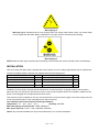
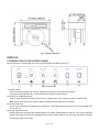
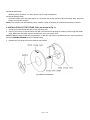
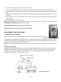
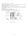
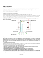
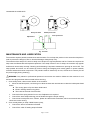
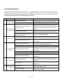
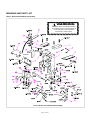
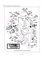
HIGH TABLE SEMI-AUTOMATIC
STRAPPING MACHINE
USER’S MANUAL
WARNING:
Read carefully and understand all ASSEMBLY AND OPERATION INSTRUCTIONS before operating.
Failure to follow the safety rules and other basic safety precautions may result in serious personal
injury.
Item# 45406
Thank you very much for choosing an Ironton™ product. For future reference, please complete the owner’s record
below:
Model: _______________
Purchase Date: _______________
Save the receipt, warranty and these instructions. It is important that you read the entire manual to become
familiar with this product before you begin using it.
This strapping machine is designed for certain applications only. The distributor cannot be responsible for issues
arising from modification. We strongly recommend this item not be modified and/or used for any application other
than that for which it was designed. If you have any questions relative to a particular application, DO NOT use this
product until you have first contacted the distributor to determine if it can or should be performed on the product.
For technical questions, please call 1-800-222-5381.
TABLE OF CONTENTS
TECHNICAL SPECIFICATIONS…………………………………………………………..………………1
GENERAL SAFETY REGULATIONS……………………………………………..………………………1
SPECIFIC OPERATION WARNINGS……………………………………………………………..………1
INSTALLATION…………………………………………………..……………..……………………………3
START-UP……………………………………………………..………………………….………………… 4
OPERATION………………………….…………..………………………………………………………… 6
ADJUSTMENT INSTRUCTIONS…………………………………………………….…….………………7
ELECTRICAL DESCRIPTION………………………….………………..…………………………………8
PARTS CLEANING…………………………………………………...……….……………………………10
MAINTENANCE AND LUBRICATION……………………………………………..………………………11
TROUBLESHOOTING…………………………………………………...……….…………………………13
DRAWING & PART LIST………………………………………………………………..………………… 14
TECHNICAL SPECIFICATIONS
Item
Description
Packing Speed
<3 second/cycle
Min Package
2in.
Tension Force
6.6lbs.-154lbs. (3kgs -70kgs)
Width of PP Strap
0.24in.–0.6in. (6-15mm), preset at 12mm
Thickness of PP Strap
0.02in.-0.0335in. (0.5mm-0.85mm)
Power Voltage
AC110V
Power Frequency
60HZ Single phase
Power
two DC motors: 90W + 60W
Motor HP
1/5 HP
Strap Core Inner Diameter
200mm
Ambient Temperature
41°F-104 °F (5-40 °C)
Relatively Humidity
35-85%RH
Transportation/ Storage Temperature
-13° - +131°F (-25- +55°C)
Machine Weight
143.2lbs.
GENERAL SAFETY REGULATIONS
1. Keep the work area clean and dry. Damp or wet work areas can result in injury.
2. Keep children away from work area. Do not allow children to handle this product.
3. Store idle equipment. When not in use, tools and equipment should be stored in a dry location to inhibit rust.
Always lock up tools and equipment, and keep out of reach of children.
4. Use the right tool for the job. Do not attempt to force small equipment to do the work of larger industrial
equipment. There are certain applications for which this equipment was designed. It will do the job better and more
safely at the capacity for which it was intended. Do not modify this equipment, and do not use this equipment for a
purpose for which it was not intended.
5. Check for damaged parts. Before using this product, carefully check that it will operate properly and perform
its intended function. Check for damaged parts and any other conditions that may affect the operation of this
product. Replace damaged or worn parts immediately.
6. Do not overreach. Keep proper footing and balance at all times to prevent tripping, falling, back injury, etc.
7. DO NOT use the equipment when tired or under the influence of drugs, alcohol, or medication. A moment
of inattention while operating this equipment may result in serious personal injury.
8. Industrial applications must follow OSHA requirements.
SPECIFIC OPERATION WARNINGS
WARNING: Read and understand all instructions BEFORE operating.
WARNING: The warnings, cautions, and instructions discussed in this instruction manual cannot
cover all possible conditions or situations that could occur. It must be understood by the operator that
common sense and caution are factors that cannot be built into this product, but must be supplied by the operator.
1. Before operating the machine, please fit over voltage and under voltage protection to the machine.
Page 1 of 26
2.
3.
4.
5.
Do not place the machine on the slant place.
Do not move the machine when machine is running.
Do not place the machine on the wet or dusty place. Keep it clean and dry.
Properly ground the machine before operation. There is danger of electric shock when it does not connect to
the ground wire or does not connect fully.
6. The sectional area of the extended flexible wire should be over 2 mm² and the length should be within 10m.
The flexible wire beyond this scope can damage the machine, and can cause fire due to hot plug and socket.
7. Wear eye or face, and hand protection. Do not wear loose clothing.
8. Keep hands or other parts of the body out of the strap chute area during operation.
9. The temperature of the heater plate is very high. Do not touch.
10. Do not insert strap while there is not a package on the operation table.
11. Do not replace any safety parts of different specifications.
12. Shut off all electric power after machine operation or servicing machine.
13. Do not use water or steam to clean the machine.
14. Do not remove the electric control box cover if not necessary. Only trained engineers are allowed to open the
electric box. Before opening, be sure to pull the power plug off.
15. The machine is used for strapping products or packages only.
16. Do not take off the panel, cover, door and other parts to use the machine. Taking off the parts will cause
machine faulty and easy to cause human injury.
17. Do not modify the machine. Use the modified machine will cause human injury.
18. Do not put the wire on the passageway of forklift. Once the coat of wire is damaged or the wire is broken, it
will cause danger.
19. Do not insert or pull out attaching plug with wet hand to avoid shocking danger.
20. Do not use the machine to strap wet products.
21. Make sure pull out the plug if the machine is not in use.
22. Do not put inflammable materials around the machine if the heater is in high temperature.
23. Keep this operation manual at your strapping machine. Refer to it often.
The following warning signs can not be removed or replaced randomly. They are labeled in the positions
that will cause danger to human body. The power supply MUST be cut off before repair the machine.
①. Warning sign 1 is used for heating positions. Do not touch the mechanical parts with the sign in case of
scalding.
Warning Sign 1
②. Warning sign 2 is used for the electric parts. It indicates danger of electric shock inside the machine after
the door is removed.
Page 2 of 26
Warning Sign 2
③. Warning sign 3 indicates that the inner gearing parts can easily clamp hands. Keep your hands away
from the parts with this label. Before maintenance, stop the machine and disconnect the plug.
Warning Sign 3
NOTE: Read the other signs carefully when operating to ensure safe and correct operation and to avoid danger.
INSTALLATION
One set of tools and spare parts is packed with each machine for use in making adjustments and for replacement
of parts as needed. Please compare your supplied tools with the following list:
DESCRIPTION
QTY
DESCRIPTION
QTY
SCREWDRIVER
1
HEXAGON SPANNER M3
1
WRENCH 8*10MM
1
HEXAGON SPANNER M4
1
WRENCH 12*14MM
1
HEXAGON SPANNER M5
1
HEXAGON SPANNER M2.5
1
HEXAGON SPANNER M6
1
Installation of the machine requires that the machine be uncrated, placed in its proper position and secured in
place (see Fig 1 for reference). Remove the screw on the top cap of speed reducer for ventilation. Make sure the
power cord is plugged into the appropriate electrical outlet.
This machine must be installed on the dry, level and hard floor near the power supply. The power supply must be
in line with the description of the nameplate on the side of machine.
The installation place must meet the following conditions:
Temperature: -4℉ - 40℉ (-20℃ - 40℃)
Humidity: ≤90%RH
Max load capacity of bottom plate: 72lb/ft² (350kg/m²)
Mini space required: 78.75in. × 59in. (2000mm×1500mm)
Others: Dry and well-ventilated, far way from smoke and fire, no corrosive substance
Page 3 of 26
Fig. 1 Installation Dimension
START-UP
1. INTRODUCTION TO THE CONTROL PANEL
The control panel is at the upper right corner of the machine front plate (see Fig.2).
Fig. 2 Control Panel
(1) Power switch
Turn on the switch (position I), then the red light is on and you can operate the machine.
Turn off the switch (position O), cut down the power, then the machine stops.
(2) Tension force adjustment knob
Turn the knob clockwise to enlarge tension force. Larger tension force, faster the speed of retreat strap.
Note: When the tension force is large, operate carefully and avoid hurt from PP strap.)
(3) Cooling time knob
Turn the knob clockwise to lengthen the cooling time. The larger the tension force is, the longer cooling time
you should set.
(4) Length adjustment knob
Rotating the knob can adjust the feeding length of the straps automatically, so that you can set up a standard
length of the strap to fit the same packages. Each scale is about 500mm. Turn the knob clockwise to enlarge
the feeding length of the straps.
Page 4 of 26
(5) Manual start button
Manually start LS4 switch, the same function as PP strap interpolation.
(6) Manual feeding button
Press this button when the green light is on, the straps can be fed manually. While retracting strap, press this
button will reset the machine.
NOTE: This machine can automatically switch off after a while of inactivity and restart as the strap is inserted.
2. INSTALLATION OF THE STRAP COIL (as shown in Fig. 3)
1. Screw off the hand wheel and take off the front strap reel.
2. Place a coil of strap on the back strap reel with correct direction allowing the shaft to poke through the plastic
wrap. Make sure the straps wheel inner diameter clip in reel center claw.
NOTE: Install the strap coil with the right direction, so that the reel will turn clockwise when the strap is pulled off.
(Refer to FEEDING STRAPS section as stated below)
3. Replace the front strap reel and reinstall the hand wheel.
Fig.3 Strap Coil Installation
Page 5 of 26
3. FEEDING STRAPS (as shown in Fig. 4)
Fig.4 Feeding strap
WARNING: Before feeding the strap, make sure that the machine is turned off and the cord plug is pulled off
from the electric outlet.
1. Pull the PP strap end until about 1 meter (3 feet) straps are off the reel.
2. Put the end of the strap through wheel (A) and (B), then to transition wheel (C), and come out from the side.
3. Insert the head of the straps to (D).
4. Continue to feed straps until it pass through the rollers (E).
5. Press the Manual feeding/ retracting button (6), the machine will run, and the strap is fed manually. Do not
release the button until the end of strap comes out from point (F).
4. The function of potentiometer on PCB
RV1
Measure the voltage between two ends of capacitance C17 by adjusting RV1. Adjusting it clockwise, the voltage
will increase and then the minimum tension increase. Adjusting it anti-clockwise, the voltage will decrease and
then the minimum tension decrease. (Usually it is pre-adjusted at factory and no need to adjust again.)
RV2
When the machine starts, it takes 15 seconds to warm up. When it warms up, the indicator on the PC board
flickers. The warm up process stops if the indicator not flickers. Adjusting RV2 clockwise, the heating voltage
between two ends of the heater increase. Adjusting it anti-clockwise, the heating voltage between two ends of the
heater decrease. (Usually it is pre-adjusted at factory and no need to adjust again if the temperature can reach
requirements.)
OPERATION
WARNING: Before connect the power, set the power switch on the position of O (OFF). Make sure the
machine is connected with the ground terminal to the earth. Do not touch heat parts, or you can be burnt.
1. Install coil A on dispenser (Refer to “INSTALLATION OF THE STRAP COIL” in START-UP section).
2. Feed the strap (Refer to “Feeding Straps” in START-UP section).
Page 6 of 26
3. Connect power plug to power source (AC 110V, 60Hz).
4. Turn on the power switch and run the machine for 15 seconds to warm up to the operating temperature.
5. Place package on the table top, directly above the sealing head. Allow the package to contact the two package
stops.
6. Manually pull the strap to encircle the package. Or press manual feeding button to gain enough for encircling
package.
7. Insert strap end into slot, then machine will work automatically. Keep your hands away of the strap and slot
during strapping.
8. After strapping, take the package away.
NOTE: Some adjustments may be required to let the machine work well. Please refer to the below section
ADJUSTMENT INSTRUCTIONS to adjust accordingly.
WARNING: DO NOT sit on this machine as a bench.
CAUTION: Take care of your fingers during operation.
ADJUSTMENT INSTRUCTIONS
1. TEMPERATURE ADJUSTMENT
Open the top cover of the machine and find the temperature adjustment knob. Refer to Fig. 5.
Fig. 5 Temperature adjustment knob
The temperature increases when turning the knob on the transformer clockwise (The larger the number pointed is,
the higher the temperature is). The adhesive affection will not be very good if the temperature too high or too low,
so adjust in small increments. Normally, switch it on 4-6.
NOTE: If the temperature is adjusted too high (above 6), the high temperature heating filament is easy to be burnt
out.
2. WIDTH ADJUSTMENT
This machine is designed specially for use with PP straps with length between 0.24in. (6mm) and 0.6in. (15mm).
Adjust the distance between (2) (3) (4) and benchmark’ width (1) or (2) to fit various width of strap. Generally, it
should be 1mm wider than actual width of PP width. If the PP with poor quality, the distance should be larger.
Otherwise send back will be a failure. Refer to Fig. 6.
1
2
5
Fig. 6 Width Adjustment
3
4
Page 7 of 26
ELECTRICAL DESCRIPTION
A circuit diagram of the electrical description is illustrated as below. See Fig. 7.
Schematic circuit diagram
Fig. 7 Schematic circuit diagram
Page 8 of 26
Below are functions of each main micro switch on circuit.
LS1: It is at the right hand of Motor M1, refer to Fig. 8. The contact point will be pushed by cam of micro-switch
when the machine is set to zero.
LS2: It is beside LS1. It detects the position of banding, retracting or cooling.
LS4: It is under the sliding board. The machine begins to pack when strap head hits the touch-contact switch
through inserting slot.
HL1: Quick heat piece is at the right side of fan 1. When the machine starts, it can reach the proper temperature
within 20 second.
Fan1: Fan, it can exhaust smoke while strapping.
M1: Main motor controls the cam, cuts straps and adhesives PP straps.
M2: Feeding and retracting strap motor. It controls sending strap and tensioning work.
LS4
FAN1
HL1
M2
M1
LS1
Fig. 8 Micro switches
Page 9 of 26
LS2
PARTS CLEANING
1. UPPER SLIDE
Always keep the upper slide well fitted with both press bars, and keep it move smoothly. Thus it is important to
keep the upper slide clean. Do the cleaning following the instructions below. Refer to Fig. 9.
¾ Remove the pull springs on the swaying rocker.
¾ Move backward the upper slide and take out.
¾ Wipe the slot between slide and press bars.
¾ Insert the lower slide into upper one, then screw the upper slide to the slot of lower one.
¾ Move the upper slide forward and backward to check whether it moves smoothly or not. If adjustment is required,
skate on the right aiming at front top slot, left slot aiming at back top slot. Assure middle knife can drop and cut.
¾ Add some oil or light lubrication to the slot between slides and guides.
¾ If the upper slide can move smoothly, but cannot move back, check if the pull spring is flexible fatigue. If so,
change it or cut it shorter.
Left press bar
Right press bar
Gap
Front point knife
后顶刀
中刀knife
Middle
前顶刀
Rear point knife
Fig. 9 Upper slide
2. Micro-switch cam
The position of micro-switch cam related to the action of micro switch LS1 and LS2. When the machine is zero set,
LS1 is close circuit and LS2 is open circuit. Because LS1 and LS2 join together, do not need to consider the
adjustment method of LS1 and LS2. Loosen the fixed screw. The cam have three faces,one high, one concave
and one normal. When LS1 adjust to the highest face, it is close circuit. When LS1 adjust to the normal face, it is
open circuit.
3. Middle knife and front top knife
Middle knife and front point knife must cooperate precisely to cut off strap. So it is very important to keep them
clean. Do the cleaning following the instructions below. See Fig. 10.
A. Remove the pull springs of middle knife and front point knife.
B. Move the up skateboard backward, take out the middle knife first and then take out the front point knife.
C. Wipe the middle knife, front top knife and knife groove clearly.
D. After cleaning, assemble the front point knife, and then the middle knife and the springs.
E. Add some lite lube to around the middle knife, front point knife and rear point knife around.
If the machine has been used for long time, and the middle knife and front point knife can not cut off the strap
smoothly, take out the middle knife, remove the screws of spring and assemble them to the other side, then
Page 10 of 26
reassemble the middle knife.
LS2
LS1
A
B
后顶刀
Rear point
knife
Adjustment
调整
中刀 point knife
Middle
前顶刀
Front point knife
Fig. 10 Knifes
MAINTENANCE AND LUBRICATION
The machine requires periodic maintenance and lubrication. Do not keep the product in the wet and moist place in
order to prevent the danger of fine or electrical damage. Always keep it dry.
The material of the strap is PP, which is easily out of shape if in high temperature and fire. Please do not place the
strap near the inflammable and explosive products. If the strap is bend or out of shape, the machine may appear
trouble and cannot strap normally. Cleaning and lubricating is important measures to prolong its service life. The
strap powder and slices can be caused by friction during the strapping and usually gather in space between
machine head and electrical component. The powders must be cleaned up in time, at least once a week. (Cut off
the power supply during cleaning.)
WARNING: Only trained or professional personnel can service the machine. Make sure the machine is cool
and the wire plug has been disconnected before servicing.
1. On a weekly basis, clean out the rubbish in the machine.
¾ Move the machine panel, use the air gun to blow the dust and use lubricant to clean the inside parts listed
below.
z The moving place of up and down slide board.
z Electric heating head moving place.
z The inside of the hole of three knifes.
¾ Check all of the spring tension force to see if adjustment is required.
¾ Check if the store strap balancing pole is flexible through the simple moving.
¾ Check how to strap with some cartons, please be careful with the default, which can see and hear and
check the correct running.
2. On a monthly basis (or strap 100000 times cycles),
¾ Check if the bolt of mechanism is flexible.
¾ Check if the roller of feeding strap is flexible.
Page 11 of 26
¾ Check if the temperature of electric heating head has changed.
¾ Check if the belt has worn.
¾ Check if the spring force is correct.
3. Once of half a year (or strap 600000 times cycles)
¾ Check the heating mechanism, change them if it is the possibility.
¾ Check if the connection parts of PC board are reliable.
¾ Check all of the switch function.
4. Once a year (or strap 1200000times cycles)
¾ Clean all of the inner parts and add lubricant.
¾ Change the bearing which it has large noise.
¾ Check if the arch spring is reliable. Change it if it can not be resetted.
WARNING: Do not add too much oil once, or oil may go into micro-switches causing malfunction.
Page 12 of 26
TROUBLESHOOTING
Warning: Please make sure turn the switch to 『O』(OFF) position. Pull out the plug and screwing out
the bolts that fix the table panel. Open the panel to adjust. It may occur shock or hurt caused by machine
start. Screw up the bolt and then get through power supply.
No
Trouble
1
No action after
insert the strap
2
3
4
5
6
Not send strap
automatically
Cause
Troubleshooting
LS4 micro switch fault
LS4 micro switch fault or shrapnel is blocked by
foreign material and cannot touch connect point.
PC board or switch power not good
Replace PC board or switch power.
The potentiometer that control the
length on null line
Adjust the feed strap knob, every scale about one
meter. Adjust clockwise, adjust scope bigger send
strap longer. No sending strap when it is in zero
position.
Thread strap incorrectly
Thread the strap according to the manual or the
diagrammatic sketch at the right side of the door.
There is foreign material in the up
and down extension
Clean the machine periodically.
The bearing of middle knife is broken
Cause by improper operation. Replace the bearing
Cutter of the middle knife is worn
There are two cutter sides. Change to another side
to continue.
Temperature adjust improper
If the max temp. can no adhesive well, adjust the
W2 on the PCB to increase the temp.
The spring on the heater fault
The spring is exhausted. Replace it.
Heater piece adjust improper
Heater piece is not in right position and touch the
PP strap or knife, so that it cannot heat. Adjust it
accordingly.
The bearing of middle knife is broken
Replace the bearing.
The temperature is too high
Check whether the fan is faulty. Repair or replace it.
The tension force is too large
Adjust to make the tension smaller. Or increase the
cooling time.
LS4 micro switch fault
LS4 contact point cannot release. Adjust the
shrapnel gap. Check if there anything blocks the
shrapnel.
LS1 not good
Cannot detect the position. PCB faulty lamp flicker.
Replace LS1.
LS2 not good
Retreat strap cannot detect the position. PCB faulty
lamp flicker. Replace LS2.
Tension is too small
Adjust to make the tension bigger. Adjust W1 on
PCB to make it bigger.
Not cut strap
Adhesive not
good
Cannot reset
Cut strap while
no tension
Page 13 of 26
DRAWING AND PART LIST
Chart 1 Knife and skateboard assembly
WARNING
All parts must be periodically inspected
and replaced if worn or broken.Failure to
do this can affect a tool's operation
and present a safety hazard.
4-DP612
DT05
4-SY616
3-DT05
DT04
ML05
DT05
Chart 1 Knife and skateboard assembly
Page 14 of 26
Chart 1 Knife and skateboard assembly
NO.
Code
Description
Qty
01
AS1-11
1# knife combination
1
02
AS1-12
2# knife combination
1
03
AS1-13
3# knife combination
1
1
A0200
Mechanism base
1
2
A0173
Right press bar
1
3
A0172
Left press bar
1
4
A0171
Up skateboard
1
5
A0191
Up skateboard barrier sheet
1
6
A0192
Skateboard extension spring
1
7
A0205
Out with adjusting block
1
8
A0214
Spring drawing board
1
9
A0204
Skateboard arm
1
10
A0201
Electric heating arm
1
11
AS1-114
1# knife
1
12
AS1-117
2# knife
1
13
AS1-118
3# knife
1
14
A0107
Cross bar
1
15
A0131
Contacts copper sleeve
1
16
A0130
Bottom slide contact
1
17
EW001
Micro switch, no roller
1
18
A0107
Cross bar
1
19
A0206
Heat-resistant cover
1
20
A1079
Electric heating head
3
21
A1081
Electric heating press sheet
3
22
A1080
Electric heating bakelite sheet
1
23
A0202
Electric head fixed block
1
24
A0203
Electric heating fixing board
1
25
A0209
Rocker arm shaft
1
26
A0210
Rocker arm shaft base
1
27
AS1-115
Knife neck
1
28
AS1-116
Knife screw
1
29
AS1-513
Cross bar screw
1
30
HL101122
Long extension spring φ1.0*φ10.8*22
1
31
A0211
Send with spring
1
32
A1100
Tensioning press spring
1
33
HY231042
Spring in knife φ2.3*φ10*42
1
34
A0132
Skateboard extension spring
1
35
A1094
Electric tension spring
1
36
HL121020
Short extension springφ1.2*φ10*20
1
Page 15 of 26
Chart 2 Cam and reduction gear box assembly
4-SY620
20
4-SY620
2-SP412
2-DT03
4-DP38
2-SY330
2-DT04
Chart 2 Cam and reduction gear box assembly
Page 16 of 26
Chart 2 Cam and reduction gear box assembly
NO.
Code
Description
Qty
1
EA012
DC cam motor
1
2
A0150
Gear box cover
1
3
A0152
Transition gear wheel
1
4
A0151
Output gear wheel
1
5
A0135
Cam shaft
1
6
DJ172912
Cushion ring φ17*29*12
2
7
DJ17298
Cushion ring φ17*29*8
2
8
DJ17296
Cushion ring φ17*29*6
1
9
DW17295
Cushion ring φ17*29*0.5
1
10
A0208
Cam spacer
1
11
A0139
Skateboard cam
1
12
AS1-207
3# knife cam
1
13
AS1-208
Electric heating cam
1
14
A0140
2# knife cam
1
15
AS1-205
1# knife cam
1
16
AS1-210
Cross bar reset cam
1
17
A0137
Retreat strap cam
1
19
AS1-215
Micro switch base sheet
1
21
EW002
Micro switch, with roller wheel
2
24
A0153
Motor fixing sleeve
1
Page 17 of 26
Chart 3 Feeding and retracting strap assembly
4-SY620
2-SY616
Chart 3 Feeding and retracting strap assembly
Page 18 of 26
Chart 3 Feeding and retracting strap assembly
No
Code
Description
Qty
1
A0180
Seat belt machine
1
3
A0181
Gear cover
1
2
A0182
Reduction gear
1
4
A0184
Eccentric shaft
1
5
A0183
Send pulley
1
6
A0220
Iron gear
1
7
A0221
Driven wheel
1
8
A0186
Band road
1
9
A0105
Adjustment board
1
10
A0188
Band road cover
1
11
A0187
Under band road
1
12
A0189
Under cover band road
1
13
A0170
Pulley gasket
2
14
A0190
Pulley shaft
1
15
A0222
aluminum insert
1
16
A0223
Plug belt adjustment edition
1
17
A0185
Tied tight rod
1
18
EA013
DC motor retreat
1
Page 19 of 26
Chart 4 Machine frame
2-DT05
8-DT08
8-DP816
2-SY512
4-SY612
4-DT06
Chart 4 Machine frame
Page 20 of 26
Chart 4 Machine frame
No
Code
Description
Qty
1
A0010
AS-50 frame
1
2
A0011
AS-50 stainless steel table panel
1
3
AS1-611
Arch support
1
4
AS1-612
Cover support protruding sleeve
1
5
A0090
Stainless steel iron blocking device
1
6
AS1-614
Guide strap pulley
1
7
A0014
pulley rack
1
8
AS1-615
Guide strap pulley shaft
1
9
A0016
Angle iron legs tube
0-2
9
A0018
Square tube legs tube
0-1
10
A0017
Angle iron beams strengthened
0-2
10
A0019
Square tube beams strengthened
0-1
11
LA1675
Screw stem universal castor
2
12
LB1675
Screw stem universal castor with brake
2
13
AS1-601
Guide strap pulley
1
14
A0027
Interrupt micro switch contact sheet
1
15
A0028
Guide strap pulley shaft
2
16
A0029
Guide strap pulley rack
1
Page 21 of 26
Chart 5 Strap reel and brake assembly
SJ56
11
SY620
12
2-ZC6003K
13
ML04
SY416
4-SS616
10
9
4-SS612
7
KS10
5
8
8-MLD06
KS10
KE05
6
Chart 5 Strap reel and brake assembly
Page 22 of 26
Chart 5 Strap reel and brake assembly
No
Code
Description
1
A0061
Outside strap reel
1
2
A0060
Inside strap reel
1
3
A0402
Brace claw
4
4
A0050
AS-50 strap reel shaft
1
5
AS1-709
strap reel handle
1
6
AS1-801
Brake rod pulley
1
7
AS1-802
Brake pulley
1
8
AS1-803A
Brake rod roller wheel support
1
9
AS1-814
Brake belt
1
10
A0015
AS-50 brake rod
1
11
A0064
Small fixed sleeve
1
12
A0404
Reel support tube
1
13
A0400
brake spring
1
Page 23 of 26
Qty
Chart 6 Electrical parts
2-SD412
Chart 6 Electrical parts
Page 24 of 26
Chart 6 Electrical parts
No
Code
Description
Qty
1
APC-10N1
PC board combination, APC-10N1
1
2
ED001
150W switch power supply
1
3
A0013
Electrical box cover
1
4
EF001
Micro fan 24VDC
1
5
EK002
Red switch
1
6
EP002
Potentiometer 250K
4
7
UN001
Rotate button (black)
3
8
EN001
Green button
1
9
EN002
Yellow button
1
10
UN002
Rotate button (red)
1
11
EF001
Micro fan 24VDC
1
12
AS1-904
Heat proof cover
1
13
A0134
Fan rack
1
Page 25 of 26
WARRANTY
1-year limited warranty
Distributed by:
Northern Tool + Equipment Co., Inc.
Burnsville, Minnesota 55306-6936
NorthernTool.com
Made in China
Page 26 of 26