1
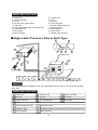
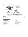
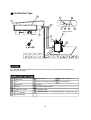
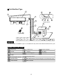
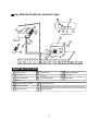
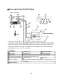
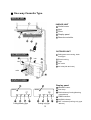
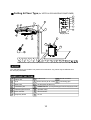
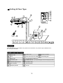
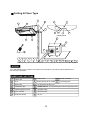
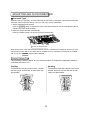
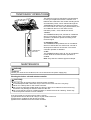
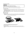
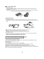
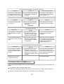
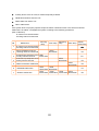
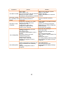
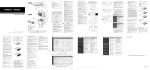
USER’S MANUAL
Cassette R-410A 50Hz
YMKFZC024-048BAM(N)-A(B)FX,YMKFZH030BAM(N)-BFX
Read this manual before installation and operation
Make sure that it is well kept for later reference
CONTENT
IMPORTANT SAFETY INFORMATION---------------------------------------------------------------------1
HINTS FOR ECONOMICAL OPERATION-----------------------------------------------------------------2
PARTS NAMES---------------------------------------------------------------------------------------------------2
ADJUSTING AIR FLOW DIRECTION-----------------------------------------------------------------------13
TEMPORARY OPERATIONS---------------------------------------------------------------------------------14
MAINTENANCE-------------------------------------------------------------------------------------------------14
AIR CONDITIONER OPERATIONS AND PERFORMANCE------------------------------------------16
INSTALLATION----------------------------------------------------------------------------------------------------17
TROUBLES AND CAUSES----------------------------------------------------------------------------------18
TROUBLES AND CAUSES(CONCERNING REMOTE CONTROLLER)-------------------------18
TROUBLES AND CAUSES(AIR CONDITIONER )----------------------------------------------------19
IMPORTANT SAFETY INFORMATION
Danger
CAUTION
Do not attempt to install this unit by yourself. This unit requires
installation by qualified persons.
DANGER
Do not attempt to service the unit yourself. This unit has no user
serviceable components. Opening or removing the cover will
expose you to dangerous voltage. Tuning off the power supply will
not prevent potential electric shock.
DANGER
Never put hands or objects into the Air Outlet of indoor or outdoor
units. These units are installed with a fan running at high speed.
To touch the moving fan will cause serious injury.
No
DANGER
To avoid the risk of serious electrical shock, Never sprinkle or
spill water or liquids on unit.
WARNING
Ventilate the room regularly while the air conditioner is in use,
especially if there is also a gas appliance in use in this room,
Failure to follow these directions may result in a loss of oxygen
in the room.
WARNING
To prevent electric shock, turn off the power or disconnect the
power supply plug before beginning any cleaning or other routine
maintenance. Follow the directions for cleaning in the Owner's
Manual.
WARNING
Do not use liquid cleaners or aerosol cleaners, use a soft and dry
cloth for cleaning the unit. To avoid electric shock, never attempt
to clean the units by sprinkling water.
Thinner
CAUTION
Do not use caustic household drain cleaners in the unit. Drain
cleaners can quickly destroy the unit components (drain pan and
heat exchanger coil etc).
NOTE
Household
Drain
Cleaner
No
For proper performance, operate the unit in temperature and
humidity ranges indicated in this owner's manual. If the unit is
operated beyond these conditions, it may cause malfunctions
of the unit or dew dripping from the unit.
1
HINTS FOR ECONOMICAL OPERATION
The following should be noticed to ensure an economical operation. (Refer to corresponding chapter
for details)
Adjust the air flow direction properly to avoid winding toward your body.
Adjust the room temperature properly to get a comfortable situation and to avoid supercooling and
superheat.
In cooling, close the curtains to avoid direct sunlight.
To keep cool or warm air in the room, never open doors or windows more often than necessary.
Set the timer for the desired operating time.
Never put obstructions near the air outlet or the air inlet. Or it will cause lower efficiency, even a
sudden stop.
If you don't plan to use the unit for a long time, please disconnect power and remove the batteries
from the remote controller. When the power switch is connected, some energy will be consumed,
even if the air conditioner isn't in operation. So please disconnect the power to save energy. And
please switch the power on 12 hours before you restart the unit to ensure a smooth operation.
A clogged air filter will reduce cooling or heating efficiency, please clean it once two weeks.
PARTS NAMES
The air conditioner consists of the indoor unit, the outdoor unit, the connecting pipe and the remote
controller.
Cassette Type
l
i
j
m
n
o
p
q
r
k
a
h
e
g
d
e
Display Panel
f
b
d
e
NOTICE!
This chart is based on 24000Btu/h type. So, a few differences may exist on the outlook and functions
from yours.
2
NAMES AND FUNCTIONS
a) indoor unit
c) remote controller
e) air-out
g) air flow louver (at air outlet)
i ) drain hose
k) drain pump (drain water from indoor unit)
m) operation lamp
o) info window
q) alarm indicator
b) outdoor unit
d) air-in
f ) air outlet
h) connecting pipe
j ) air inlet (with air filter in it)
l ) temporary button
n) timer indicator
p) frost indicator
r) infrared signal receiver
High-static Pressure Parvis Split Type
k
l
f
a
g
m
d
n
p
o
Display Panel
b
k
j
d
i
h
e
NOTICE!
This chart is based on 24000Btu/h type. So, a little differences may exist on the outlook and functions
from yours.
NAMES AND FUNCTIONS
a
indoor unit
outdoor unit
c
remote controller
air-inlet
b
e
d
g
air-out
f
air outlet
heat exchanger
h
connecting pipe
i
drain hose
j
E-Box
k
infrared signal receiver
l
temporary button
m
operation lamp
o
PRE-DEF indicator (cooling and heating type) or fan only indicator (cooling only type)
n
timer indicator
p
alarm indicator
3
Duct and Ceiling Type
f
k
i
l
h
a
m
j
d
g
n
o
p
b
e
d
d
NOTICE!
This chart is based on 24000Btu/h type. So, a few differences may exist on the outlook and
functions from yours.
NAMES AND FUNCTIONS
a) indoor unit
b) outdoor unit
c) remote controller
d) air-in
e) air-out
f ) air outlet
g) air flow louver (at air outlet)
h) connecting pipe
i ) drain hose
j ) air inlet (with air filter in it)
k) infrared signal receiver
l ) manual button
m) operation lamp
n) timer indicator
o) PRE-DEF indicator
p) alarm indicator
(NOTICE: In the case of "cooling only type", it is the "FAN ONLY" indicator.)
4
For Slim Duct Type
e
j
k
a
f
m
l
o
n
Display Panel
b
h
g
i
d
NOTICE!
The chart based on one model of our product is for reference only, which may be different from
the unit you purchased.
NAMES AND FUNCTIONS
a
indoor unit
d
g
air-in
b
e
drain hose
h
i
Air-out
j
infrared signal receiver
k
temporary button
l
operation lamp
m
timer indicator
n
FAN/DEF indicator (For cooling and heating type, it s DEF.,for cooling only type, it s FAN)
o
Alarm Indicator
outdoor unit
air flow louver (at air outlet)
c
remote controller
f
connecting pipe
E-Box
,
5
,
For Slim Duct Type
f
k
l
a
h
m
g
n
p
o
Display Panel
b
j
i
d
e
NOTICE!
This chart is based on 24000Btu/h. type. So, a few differences may exist on the outlook and functions from yours.
NAMES AND FUNCTIONS
a
indoor unit
d
air-inlet
outdoor unit
c
remote controller
air-out
f
air- outlet
h g
connecting pipe
i
drain hose
b
e
j
E-Box
k
infrared signal receiver
l
temporary button
m
operation lamp
o
PRE./DEF.indicator (cooling and heating type) or fan only indicator (cooling only type)
n
timer indicator
p
alarm indicator
6
For Slim Duct with air inlet box Type
k
l
f
a
g
m
d
n
p
o
Display Panel
b
f
j
d
i
h
e
NAMES AND FUNCTIONS
a
indoor unit
b
outdoor unit
c
remote Controller
d
g
air-outlet
e
air-out
f
air- inlet
heat exchanger
h
connecting pipe
i
drain hose
j
E-Box
k
infrared signal receiver
l
temporary button
m
operation lamp
o
PRE./DEF.Indicator (Cooling and heating type) or fan only indicator (cooling only type)
n
timer indicator
p
alarm indicator
7
Four-way Cassette(slim) Type
Indoor Unit Assy
9
1
11
10
Manual
OPERATION TIMER DEF./FAN. ALARM
12
13
14
15
6
Control board
5
4
8
2
7
Inlet
3
Outlet
Outdoor Unit Assy
This picture is based on the type of 18000Btu/h, So the appearance and function may be
slightly different from the unit you purchased.
Parts Names:
1
4
7
9
10
13
15
2 Outdoor Unit
3 Remote Controller
Indoor Unit
5 Vertical louver
6 Connecting pipe
Air outlet
Air
Inlet
(Air
filter
installed
inside
to
prevent the dust)
8
Drain hose
Drain Pump (Internal installed),water drain from indoor unit.
12 Run lamp
Infrared Signal receiver 11 Manual button
14 Defrost indicator heating/cooling type or fan indicator (cooling
Timer indicator
only type)
Alarm indicator
8
One-way Cassette Type
INDOOR UNIT
INDOOR UNIT
Outlet louver
Inlet
Filter
Display panel
Remote controller
OUTDOOR UNIT
OUTDOOR UNIT
Refrigerant connecting, drain
hose pipe
inlet
Electric wiring
inlet
Trap
Air outlet
Air inlet(side and rear)
outlet
DISPLAY PANEL
Display panel
MANUAL button
MANUAL
Run lamp
MANUAL
FAN indicator(Cooling/Heating
RUN
TIMER DEF ALARM
RUN
TIMER FAN ALARM
type without)
TIMER indicator
ALARM indicator
16
Cooling&Heating type
16
Cooling-only type
9
DEF. indicator(Cooling-only type
without)
Ceiling & Floor Type (for VERTICAL DISCHARGE AIR CONDITIONER)
l
m
J
g
n
o
f
k
Display Panel
b
p
d
NOTICE!
The chart based on one model of our product is for reference only, which may be different from
the unit you purchased.
NAMES AND FUNCTIONS
a
indoor unit
d
g
i
installation part
j
FAN/DEF indicator (For cooling and heating type, it s DEF.,for cooling only type, it s FAN)
k
infrared signal receiver
l
operation lamp
m
timer indicator
n
alarm indicator
o
temporary button
P
air-out
air-in
b
e
air flow louver (at air outlet)
drain hose
h
air inlet (with air filter in it)
outdoor unit
c
remote controller
f
connecting pipe
,
10
,
Ceiling & Floor Type
l
m
J
g
n
o
f
k
Display Panel
b
d
p
NOTICE!
The chart based on one model of our product is for reference only, which may be different from
the unit you purchased.
NAMES AND FUNCTIONS
a
indoor unit
d
g
i
installation part
j
FAN/DEF indicator (For cooling and heating type, it s DEF.,for cooling only type, it s FAN)
k
infrared signal receiver
l
operation lamp
m
timer indicator
n
alarm indicator
o
temporary button
P
air-out
air-in
b
e
air flow louver (at air outlet)
drain hose
h
air inlet (with air filter in it)
outdoor unit
c
remote controller
f
connecting pipe
,
11
,
Ceiling & Floor Type
i
a
g
k
e
o
f
p
m
l
n
j
Display Panel
h
b
d
d
p
NOTICE!
The chart based on one model of our product is for reference only, which may be different from
the unit you purchased.
NAMES AND FUNCTIONS
a
indoor unit
d
g
i
installation part
j
FAN/DEF indicator (For cooling and heating type, it s DEF.,for cooling only type, it s FAN)
k
infrared signal receiver
l
operation lamp
m
timer indicator
n
alarm indicator
o
temporary button
P
air-out
air-in
b
e
air flow louver (at air outlet)
drain hose
h
air inlet (with air filter in it)
outdoor unit
c
remote controller
f
connecting pipe
,
12
,
ADJUSTING AIR FLOW DIRECTION
Cassette Type
While the unit is in operation, you can adjust the air flow louver to change the flow direction and naturalize the room temperature evenly. Thus you can enjoy it more comfortably.
1. Set the desired air flow direction.
Push the SWING button to adjust the louver to the desired position and push this button again to
maintain the louver at this position.
2. Adjust the air flow direction automatically.
Push the SWING button, the louver will swing automatically.
ADJUST IT UP AND DOWN
While this function is set, the swing fan of indoor unit runs; otherwise, the swing fan doesn't run. The
0
swing scale of every side is 30 . When the air conditioner isn't in operation (including when "TIMER
ON" is set), the SWING button will be disabled.
Duct and Ceiling Type
The following is how to adjust air flow direction when air outlet part (separately saled) is
used with the indoor unit.
Cooling
Heating
To effectively cool the whole room, please
set the louver so that the air can come out
horizontally.
To effectively heat the bottom of the room,
Please set the louver so that the air can
come out downwards.
13
TEMPORARY OPERATIONS
This function is used to operate the unit temporarily
in case you misplace the remote controller or its
batteries are exhausted. Two modes including AUTO
and mandatory COOL can be selected through the
TEMPORARY BUTTON on the air inlet grill control
box of the indoor unit. Once you push this button, the
air conditioner will run in such order: AUTO,
mandatory COOL, OFF, and back to AUTO.
1. AUTO
The OPERATION lamp is lit, and the air conditioner
will run under AUTO mode. The remote controller
operation is enabled to operate according to the
received signal.
2. mandatory COOL
The OPERATION lamp flashes, the air conditioner
will turn to AUTO after it is enforced to cool with a
wind speed of HIGH for 30 minutes. The remote
controller operation is disabled.
TEMPORARY
BUTTON
3. OFF
The OPERATION lamp goes off. The air conditioner
is OFF while the remote controller operation is
enabled.
Note: Only take the cassette type as example.
MAINTENANCE
WARNING
WARNING
Before you clean the air conditioner, be sure to disconnect the power supply plug.
Cleaning the indoor unit and remote controller
CAUTIONS
Use a dry cloth to wipe the indoor unit and remote controller.
A cloth dampened with cold water may be used on the indoor unit if it is very dirty.
Never use a damp cloth on the remote controller.
Do not use a chemically-treted duster for wiping or leave such material on the unit for long,
because it may damage or fade the surface of the unit.
Do not use benzine, thinner, polishing powder, or similar solvents for cleaning. These may
cause the plastic surface to crack or deform.
If you do not plan to use the unit for at least 1 month.
(1) Operate the fan for about half a day to dry the inside of the unit.
(2) Stop the air conditioner and disconnect power.
(3) Remove the batteries from the remote controller.
14
Checks before operation
CAUTIONS
Check that the wiring is not broken off or disconnected.
Check that the air filter is installed. (Some air-conditioners haven't air filters.)
Check that the outdoor unit air outlet or inlet is not blocked.
Before you clean the air conditioner, be sure to disconnect the power supply plug.
Cleaning the air filter
The air filter can prevent the dust or other particulate from going inside .In case of blockage of the filter , the
working efficiency of the air conditioner may greatly decrease .Therefore , the filter must be cleaned once two
weeks during long time usage.
If the air conditioner is positioned in a dust place , the cleaning frequency of the air filter must be increased .
If the accumulated dust is too heavy to be cleaned , please replace the filter with a new one(replaceable air
filter is an optional fitting).
Cassette Type
1. Open the air-in grill
Press the couple of grill's buttons simultaneously as indicated in sketch A. Then pull down the air-in grill.
Cautions: The control box cables ,which are originally connected with the main body electrical terminators
must be pulled off before doing as indicated above.
A
B
2. Take out the air-in grill (together with the air filter shown in Sketch B)
o
Pull the air-in grill down at 45 and lift it up to take out the grill.
3. Dismantle the air filter
4. Clean the air filter(Vacuum cleaner or pure water may be used to clean the air filter. If the dust
accumulation is too heavy , please use soft brush and mild detergent to clean it and dry out in cool
place) .
15
Duct and Ceiling Type
1. Open the air-in grill
Push the grill switches towards the middle simultaneously as indicated in follow figure sketch.
Then pull down the air-in grill.
Cautions: The control box cables ,which are originally connected with the main body electrical
terminators must be pulled off before doing as indicated above.
Clip
Open<
2. Take out the air-in grill.
3. Dismantle the air filter
4. Clean the air filter (Vacuum cleaner or pure water may be used to clean the air filter. If the dust
accumulation is too heavy , please use soft brush and mild detergent to clean it and dry out in cool
place) .
Fig. 1
Fig. 2
The air-in side should face up when using vacuum cleaner. (See Fig. 1)
The air-in side should face down when using water. (See Fig. 2)
Cautions : Do not dry out the air filter under direct sunshine or with fire.
5. Re-install the air filter
6. Install and close the air-in grill in the reverse order of step 1 and 2 and connect the control box
cables to the corresponding terminators of the main body .
Note: High-static Pressure Parvis Split Type has no air filter.
AIR CONDITIONER OPERATIONS AND PERFORMANCE
Three-minute protection feature
A protection feature prevents the air conditioner from being activated for approximately 3 minutes
when it restarts immediately after operation.
Power failure
Power failure during operation will stop the unit completely.
The OPERATION lamp on the indoor unit will start flashing when power is restored.
To restart operation, push the ON/OFF button on the remote controller.
Lightning or a car wireless telephone operating nearby may cause the unit to malfunction.
Disconnect the unit with the power and then connect the unit with the power again. Push the ON/OFF
button on the remote controller to restart operation.
16
Air conditioner operating conditions
For proper performance, run the air conditioner under the following temperature conditions:
o
o
Outdoor temperature: 21 to 43 C or 21 to 52 C(T3 type)
o
Room temperature: 17 to 32 C
Cooling operation
Heating operating
(cooling only type without)
CAUTION
Room relative humidity less than 80%. If the air conditioner
operates in excess of this figure, the surface of the air conditioner
may attract condensation.
o
Outdoor temperature: -5 to 24 C
o
Room temperature: 0 to 30 C
o
Dry operation
o
Outdoor temperature: 11 to 43 C or 21 to 52 C(T3 type)
o
Room temperature: 17 to 30 C
If air conditioner is used beyond the above conditions, safety protection features may come into
operation.
INSTALLATION
Location:
During cooling operation, the air conditioner will dry the room air, so please fix a pipe to drain all the
water away from the air conditioner.
Please let the indoor unit more than one metre away from the TV set and the radio in order to avoid
the picture and noise interference.
Powerful radio transmitters or any other devices radiating high frequency radio waves can cause
the air conditioner to malfunction. Please consult the dealer where you purchased the air conditioner before installing it.
Don't fix the unit in the dangerous region with combustible gas or volatile matter.
If the air conditioner operates in an atmosphere containing oils (machine oil), salt (near a coastal
area), sulfide gas (near a hot spring), etc., such substances may lead to failure of the air conditioner.
Be careful of noise or vibrations
Please fix the unit in the stable place to avoid the noise or vibrations.
The noise near the air outlet of the outdoor unit may enter the air exit.
Locate the outdoor unit where noise emitted by it or hot air from its air outlet will cause no nuisance
to your neighbours.
If the air conditioner sounds abnormal during operation, contact the dealer where you purchased the
air conditioner.
Wire
To avoid the electric shock, please link the air conditioner with the ground. The plug in the air
conditioner has joined the ground wiring, please don't change it freely.
The power socket is used as the air conditioner specially.
Don't pull the power wiring hard.
When linking the air conditioner with the ground, observe the local rulers.
If necessary, use the power fuse or the circuit, breaker or the corresponding scale ampere.
If you want to change the power wiring, please contact the centre service of the local MD electric
appliance.
Relocation
If you move out or if it is desired to relocate the air conditioner, consult your dealer, because special
skills to withdraw Freon, purge air and perform other operations are required.
17
TROUBLES AND CAUSES
Before you ask for servicing or repairs, check the following points.
Recheck
Inoperative
The power fuse is blown or the circuit breaker has been tripped.
The batteries in the remote controller are exhausted.
The timer is set.
Does not cool or heat well.
The air inlet or outlet of the outdoor unit is blocked.
Doors or windows are open.
The air filter is clogged with dust.
The louver is not at the correct position.
The fan speed is set to low.
The temperature setting is too high or too low.
These are not failures
Room air is smelly.
A bad odor comes from the air conditioner.
Smells impregnated in the wall, carpet, furniture, clothing, or furs, are coming out. A white mist
of chilled air or water is generated from the outdoor unit.
CAUTION
If any of the following conditions occur, stop the air conditioner immediately, set to off the power
switch, and contact the dealer:
The indicator lamps flash rapidly (five times per second), you disconnect the unit with the power
and then connect the unit with the power again after two or three minutes but the lamps still flash.
Switch operations are erratic.
The fuse is blown frequently or the circuit breaker is tripped frequently.
Foreign matter or water has fallen inside the air conditioner.
Any other unusual condition is observed.
(CONCERNING REMOTE
CONTROLLER)
TROUBLES AND CAUSES
Before you ask for servicing or repairs, check the following points.
Setting Change is Impossible
Symptoms
The fan speed can not be
changed.
Causes
Reason and Disposal
Check whether the MODE
indicated on the display is
"AUTO"
When the automatic mode is
selected, the air conditioner
automatically selects the fan
speed.
Check whether the MODE
indicated on the display is
"DRY"
When dry operation is selected,
the air conditioner automatically
select the fan speed. The fan
speed can be selected during
"COOL" and "FAN ONLY", and
"HEAT"
18
The Transmission Indicator " " Never Comes On
Symptoms
Reason and Disposal
Causes
The remote control signal is
not transmitted even when
the ON/OFF button is pushed.
Check whether the batteries
in the remote controller are
exhausted.
The remote control signal is
not transmitted, because the
power supply is off.
The Display Never Comes On
Symptoms
Reason
Causes
Check whether the MODE
indicated on the display is
"FAN ONLY".
FAN ONLY
The TEMP. indicator does
not come on.
The temperature cannot be
set during fan only operation.
The Display Goes Off
Symptoms
Reason
Causes
The indication on the display
disappears after a lapse of
time.
Check whether the timer
operation has come to an
end when the OFF TIMER
is indicated on the display.
The air conditioner operation
stops since the set time
elapsed.
The ON TIMER indicators
go off after a lapse of certain
time.
Check whether the timer
operation is started when
the ON TIMER is indicated
on the display.
When the time set to start the
air conditioner is reached, the
air conditioner will automatically
start and the appropriate
indicator will go off.
The Signal Receiving Tone does Not Sound
Symptoms
No receiving tone sounds
from the indoor unit even
when the ON/OFF button is
pushed.
Disposal
Causes
Check whether the signal
transmitter of the remote
controller is properly directed
to the receiver of the indoor
unit when the ON/OFF button
is pushed.
Buttons on the remote
controller don't work.
Direct the signal transmitter of
the remote controller to the
receiver of the indoor unit, and
then repeatly push the ON/
OFF button twice.
Press Reset button.
(Air conditioner)
TROUBLES AND CAUSES
If one of the following malfunctions occur, stop operation, shut off the power, and contact with your
dealer.
The operation lamp is flashing rapidly (5Hz).
This lamp is still flashing rapidly after turn off the power and turn on again. (See in Table 8-1)
Remote controller receives malfunction or the button does not work well.
19
A safety device such as a fuse, a breaker frequently actuates.
Obstacles and water enter the unit.
Water leaks from indoor unit.
Other malfunctions.
If the system does not properly operate except the above mentioned cases or the above mentioned
malfunctions is evident, investigate the system according to the following procedures.
(See in Table 8-2)
In-outdoor unit communication
checking channel is abnormal
N0.
Malfunction
Running
lamp
1
In-outdoor unit communication
checking channel is abnormal
2
Room temperature sensor
checking channel is abnormal
3
Evaporator Pipe temperature sensor LED1
checking channel is abnormal
Quick-flash
4
Condensator Pipe temperature sensor
checking channel is abnormal
5
Water-level alarm malfunction
6
EEPROM malfunction
7
Outdoor malfunction
timer lamp
defrosting
lamp
alarm lamp
display
(nixie tube)
E1
LED2
Quick-flash
E2
E3
LED3
Quick-flash
E4
LED4
Quick-flash
LED1
LED2
Quick-flash Quick-flash
LED2
LED3
LED4
LED1
Quick-flash Quick-flash Quick-flash Quick-flash
20
E8
E7
E6
Symptoms
Solution
Causes
Power failure.
Power switch is off.
Unit does not start Fuse of power switch may have burned.
Batteries of remote controller
exhausted or other problem of controller.
Air flowing normally Temperature is not set correctly.
but completely can't Be in 3 minutes protection of
compressor.
cooling
Units start or stop
frequently
Refrigerant is too little or too much.
Air or no concreting gas in the
refrigerating circuit.
Compressor is malfunction.
Voltage is too high or too low.
System circuit is blocked.
Outdoor unit and indoor unit heat
exchanger is dirty.
The air filter is dirty.
Inlet/outlet of indoor/outdoor units is
blocked.
Low cooling effect Doors and windows are open
Sunlight directly shine.
Too much heat resource.
Outdoor temp. is too high.
Leakage of refrigerant or lack of
refrigerant.
Low heating effect
Outdoor temperature is lower than 7 C .
Doors and windows not completely
closed.
Leakage of refrigerant or lack of
refrigerant.
21
Wait for the comeback of power.
Switch on the power.
Replace the fuse.
Replace the batteries or check the
controller.
Set the temperature properly.
Wait.
Check leakage, and rightly recharge
refrigerant.
Vacuum and recharge refrigerant.
Maintenance or change compressor.
Install manostat.
Find reasons and solution.
Clean the heat exchanger.
Clean the air filter.
Eliminate all dirties and make air
smooth.
Close doors and windows.
Make curtains in order to shelter from
sunshine.
Reduce heat source.
AC cooling capacity reduces (normal).
Check leakage and rightly recharge
refrigerant.
Use heating device.
Close doors and windows.
Check leakage and rightly recharge
refrigerant.
MDV07U-019DW(G)
202000170285
20100630
2010 Johnson Controls, Inc.
www.johnsoncontrols.co m
UMKJZ-AM--110802
Johnso n Controls reserve the right to change product features without prior notice .