1
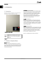
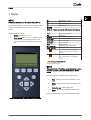
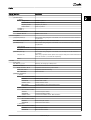
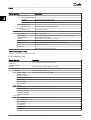
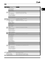
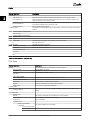
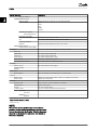
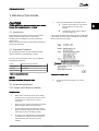
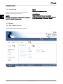
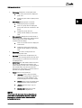
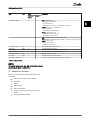
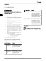
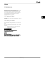
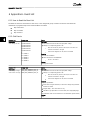
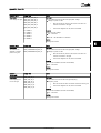
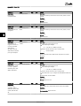
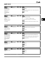
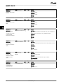
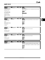
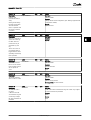
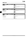
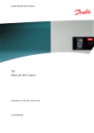
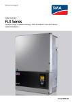
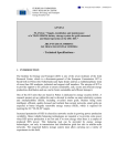
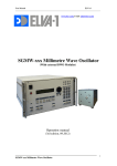
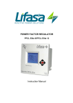
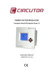
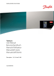
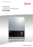
MAKING MODERN LIVING POSSIBLE
TLX
User Manual
Three-phase – 6k, 8k, 10k, 12.5k and 15k
SOLAR INVERTERS
Contents
Contents
1 Introduction
2
1.1 Introduction
2
1.2 Definition of Operation Modes
2
2 Display
3
2.1.1 View
4
2.1.2 View 2
4
2.1.3 Status
4
2.1.4 Production Log
6
2.1.5 Setup
8
3 Web Server Quick Guide
11
3.1 Introduction
11
3.2 Supported Characters
11
3.3 Access and Initial Setup
11
3.3.2 Setup Wizard
12
3.4 Operation
12
3.4.1 Web Interface Structure
12
3.4.2 Plant, Group and Inverter Views
14
3.5 Additional Information
15
4 Troubleshooting
16
5 Maintenance
17
5.1.1 Cleaning the Cabinet
17
5.1.2 Cleaning the Heatsink
17
6 Appendix A - Event List
18
6.1.1 How to Read the Event List
18
6.1.2 Grid Events
18
6.1.3 PV Events
21
6.1.4 Internal Events
22
6.1.5 Communication Events
29
L00410310-09_02
1
1 1
Introduction
1 Introduction
Connecting (Green LED flashing)
The inverter starts up when the PV input voltage reaches
250 V. The inverter performs a series of internal self-tests,
including PV auto detection and measurement of the
resistance between the PV arrays and earth. Meanwhile, it
also monitors the grid parameters. When the grid
parameters have been within the specifications for the
required amount of time (depends on grid code), the
inverter starts to energise the grid.
1.1 Introduction
This manual provides information on functionality and
maintenance of the TLX Series solar inverter.
On grid (Green LED on)
The inverter is connected to the grid and energises the
grid. The inverter disconnects if: It detects abnormal grid
conditions (depending on grid code), if an internal event
occurs or if no PV power is available (no power is supplied
to the grid for 10 minutes). It then goes into connecting
mode or off grid mode.
Fail Safe (Red LED flashing)
If the inverter detects an error in its circuits during the selftest (in connecting mode) or during operation, the inverter
enters fail safe mode, disconnecting from PV. The inverter
will remain in fail safe mode until PV power has been
absent for a minimum of 10 minutes, or the inverter has
been shut down completely (AC and PV).
Illustration 1.1 Solar Inverter
Refer to 4 Troubleshooting for further information.
CE marking - This certifies the conformity of the
equipment with the regulations which apply in
accordance with the directives 2004/108/EC and
2006/95/EC.
Table 1.1
1.2 Definition of Operation Modes
Off grid (LEDs off)
When no power has been delivered to the AC grid for
more than 10 minutes, the inverter disconnects from the
grid and shuts down. This is the normal night mode. The
user and communication interfaces are still powered for
communication purposes.
2
L00410310-09_02
Display
2 Display
NOTE
F1
View 1/View 2 - Screen
F2
Status Menu
F3
Production Log Menu
The integrated display on the inverter front gives the user
access to information about the PV system and the
inverter.
F4
Setup Menu
The display has two modes:
Home
Return to View Screen
OK
Enter/select
The display activates up to 10 seconds after power up.
1.
2.
Normal: The display is in use.
Power saving: After 10 min. of no display activity
the back light of the display turns off to save
power. Re-activate the display by pressing any
key
NOTE
2 2
When an F-key is selected the LED above it will light up.
Arrow up
A step up/increase value
Arrow Down
A step down/decrease value
Arrow Right
Moves cursor right
Arrow Left
Moves cursor left
Back
Return/de-select
On - Green LED
On/flashing=On grid/Connecting
Alarm - Red LED
Flashing=Fail safe
The inverter is configured as master.
Icons can be found in the top right
corner.*
The inverter is connected to a master.
Icons can be found in the top right
corner.*
Table 2.1 Legend to Illustration 2.1
*TLX
Pro and TLX Pro+ only.
NOTE
The contrast level of the display can be altered by pressing
the arrow up/down button while holding down the F1
button.
The menu structure is divided into four main sections
1.
View - presents a short list of information, read
only.
2.
Status - shows inverter parameter readings, read
only.
3.
Production log - shows logged data.
4.
Setup - shows configurable parameters, read/
write.
See the following sections for more detailed information.
Illustration 2.1 Overview of Display Buttons and Functionality
L00410310-09_02
3
2 2
Display
2.1.1 View
Parameter
Description
Mode: On grid
Displays present inverter mode. See operation mode definitions
Prod. today: 12345 kWh
Energy production today in kWh. Value from inverter or S0 energy-meter
Output Power: 12345 W
Current output power in Watt
[ --- utilization bar --- ]
Shows level of inverter utilisation as % of max. utilisation
Table 2.2 Menu Structure - View
2.1.2 View 2
Pressing F1 once more will result in the following screen
being shown (see section on buttons for more
information):
Parameter
Description
Grid mgmt:
Indicates whether or not any grid management measures are in effect.
Hidden if no grid management measures are in effect.
Performance ratio: 87 %*
Total CO2 saved:123
Performance ratio is shown if irradiation sensor is available (local or master).
T*
Lifetime CO2 emission saved, calculated using configured value.
Total revenue: 234.5 Euro
*
Lifetime revenue, calculated using configured value.
Table 2.3 Menu Structure- View 2
* For TLX Pro only.
2.1.3 Status
Display Functions
Description
[-] Ambient Conditions
Only applicable if sensors are connected
Irradiance. “NC” if not connected
Irradiance: 1400W/m2
PV module temp: 100
oC
PV module temperature. “NC” if not connected
Ambient temp: 20 oC
Ambient temperature. “NC” if not connected
Irr. sensor temp: 20 oC
Irradiation sensor temperature. “NC” if not connected
[-] Photovoltaic
[-] Present values
[-] PV input 1
Voltage: 1000V
Voltage detected at PV input 1
Current: 15.0 A
Current detected at PV input 1
Power 10000 W
Power detected at PV input 1
[+] PV input 2
[+] PV input 3
Not visible if inverter type is 10 kW
[-] Insulation Resistance
Resistance: 45 MΩ
PV insulation resistance at start-up
[-] PV Input Energy
Total: 369000kWh
Daily production of all PV inputs
PV1: 123000 kWh
Daily production of PV input 1
PV2: 123000 kWh
Daily production of PV input 2
PV3: 123000 kWh
Daily production of PV input 3. Not visible if inverter only has 2 PV inputs.
[-] PV Configuration
PV input 1: Individual
Configuration of PV input 1. The configuration is only shown when the inverter is in
Connecting or On grid mode.
PV input 2: Individual
PV input 3: Individual
4
Not visible if inverter only has 2 PV inputs.
L00410310-09_02
Display
Display Functions
Description
[-] AC-grid
2 2
[-] Present Values
[-] Phase 1
Voltage: 250 V
Voltage on phase 1
Current: 11.5 A
Current on phase 1
Frequency: 50 Hz
Frequency on phase 1
Power: 4997 W
Power on phase 1
[+] Phase 2
[+] Phase 3
[-] Residual Current Monitor
Current: 350 mA
Residual current in mA
[-] Grid management
[-] Apparent power (S)
Plant max. (S): 15 kVA
[-] Active power (P)
If the inverter being configured is the Master, then the entered limit will be treated as
the plant limit.
If not configured the value will not be shown
If the inverter being configured is the Master, then the entered limit will be treated as
the plant limit.
Limit type: Off
Max. power (P): 15 kW
PLA: 100%
[-] Reactive power (Q)
Set-point: Off
Only shown if Limit type is Off
If the inverter being configured is the Master, then the setpoint will be distributed to
all inverters.
When using a dynamic reactive power mode ( Q(U) or PF(P) ) the inverter status will be
shown as Constant Q or Constant PF respectively.
Value: [-] Inverter
Country: Misc
Grid: VDE 126_1_1_A1
Read only. To change go to Setup menu
[-] Internal Conditions
Power module 1: 100 oC
Temperature detected at the power module
PCB1 (AUX): 100 oC
Temperature detected internally
Fan 1: 6000 RPM
Speed of the fan
[-] Serial no. and SW ver.
[-] Inverter
Prod- and serial number:
123A4567
Inverter product number
123456A789
Inverter serial number
Software version:
Inverter software version
MAC address:
The MAC address of the communication board
...
[-] Control board
Part- and serial number:
123A4567
Control board part number
123456A789
Control board serial number
Software version:
Control board software version. Build number: 3.
[-] Power board
Part- and serial number:
123A4567
Power board part number
123456A789
Power board serial number
[-] AUX board
Part- and serial number:
123A4567
Aux board part number
123456A789
Aux board serial number
L00410310-09_02
5
Display
Display Functions
Description
[-] Communication board
2 2
Part- and serial number:
123A4567
Communication board part number
123456A789
Communication board serial number
Software version:
Communication board software version. Build number: 1.
[-] Func. Safety Processor
Software version:
Functional Safety processor software version
[-] Display
Software version:
Display software version
[-] Upload status
Upload status: Off
Current upload status
* Signal strength:
Signal strength. Should preferably be between 16-31. '-' indicates no signal.
* GSM status: None
Current GSM network status
Network:
Network to which the modem is connected
Failed uploads: 0
Number of consecutive failed uploads
Last error: 0
Last error ID, please see the GSM manual for further assistance
-
Time and date of last error
Last upload:
-
Time and date of last successful upload
Table 2.4 Menu Structure - Status
* Visible when communication channel is set to GSM.
2.1.4 Production Log
Display Functions
Description
Total production:
123456 kWh
Total production since installation of inverter
Total operating time:
20 hours
Total operating time since installation of inverter
[-] Production log
[-] This week
Monday: 37 kWh
Production from this week
Production from one day shown in KWh
Tuesday: 67 kWh
Wednesday: 47 kWh
Thursday: 21 kWh
Friday: 32 kWh
Saturday: 38 kWh
Sunday: 34 kWh
[-] Past 4 weeks
This week: 250 kWh
Production from this week shown in KWh
Last Week: 251 KWh
2 Weeks ago: 254 KWh
3 Weeks ago: 458 KWh
4 Weeks ago: 254 KWh
[-] This year
January: 1000 kWh
Production from one month shown in kWh
February: 1252 KWh
March: 1254 KWh
April: 1654 KWh
May: 1584 KWh
June: 1587 KWh
July: 1687 KWh
6
L00410310-09_02
Display
Display Functions
Description
August: 1685 KWh
2 2
September: 1587 KWh
October: 1698 KWh
November: 1247 KWh
December: 1247 KWh
[-] Past years
Yearly production, up to 20 years back
This year: 10000 kWh
Production from this year shown in KWh
Last year: 10000 kWh/m2
2 years ago: 10000 kWh/m2
3 years ago: 10000 kWh/m2
...
20 years ago: 10000 kWh/m2
[-] Irradiation log
Only visible if it contains non-zero values
[-] This week
Irradiation from this week
Monday: 37 kWh/m2
Tuesday: 45
Irradiation from one day shown in kWh/m2
kWh/m2
Wednesday: 79 kWh/m2
Thursday: 65 kWh/m2
Friday: 88 kWh/m2
Saturday: 76 kWh/m2
Sunday: 77 kWh/m2
[-] Past 4 weeks
Irradiation from this week shown in kWh/m2
This week: 250 kWh/m2
Last week: 320 kWh/m2
2 weeks ago: 450 kWh/m2
3 weeks ago: 421 kWh/m2
4 weeks ago: 483 kWh/m2
[-] This year
January: 1000 kWh/m2
Irradiation from one month shown in kWh/m2
February: 1000 kWh/m2
March: 1000 kWh/m2
April: 1000 kWh/m2
May: 1000 kWh/m2
June: 1000 kWh/m2
July: 1000 kWh/m2
August: 1000 kWh/m2
September: 1000 kWh/m2
October: 1000 kWh/m2
November: 1000 kWh/m2
December: 1000 kWh/m2
[- ] Past years
Yearly irradiation up to 20 years back are shown
This year: 10000 kWh/m2
Last year: 10000 kWh/m2
2 years ago: 10000 kWh/m2
3 years ago: 10000 kWh/m2
...
20 years ago: 10000 kWh/m2
[-] Time stamps
Installed: 31-12-07
Date of first grid connection
Power down: 21:00:00
When the inverter was last connected to grid
Prod. initiated: 06:00:00
When the inverter first connected to grid today
L00410310-09_02
7
Display
Display Functions
Description
[-] De-rating
2 2
Total de-rate: 0 h
Period of time the inverter has limited power production in total, shown in hours.
Freq. stabiliza.: 0 h
Period of time the inverter has limited power production due to frequency support. Only
visible if enabled by the current grid code.
Pwr level adjust: 0 h
Period of time the inverter has limited power production due to Power level adjustment.
Only visible if enabled by the current grid code.
Reactive Power: 0 h
[-] Reactive Power
Due to reactive energy support.
Only visible if the current grid code is an MV country or custom, and in TLX+ and TLX Pro+
variants.
[-] Reactive Energy (underexcited):
1000 000 VArh
[-] Reactive Energy (overexcited):
1000 000 VArh
[-] Event log
Latest event:
0
The latest event is displayed. The number is for service purposes.
Zero indicates no error.
[-] Last 20 events
The latest 20 events are displayed
1 : 29-01-2009 14:33:28
Date and time of the event
Grid 29 off
Group - ID - Status of the event
2 : 29-01-2009 14:33:27
Grid 29 on
20:
Table 2.5 Menu Structure - Production Log
2.1.5 Setup
Display Functions
Description
[-] Relay
Set relay functionality to either Alarm or Self-consumption
Function: Alarm
Default setting of Function
Stop Alarm
Stop alarm
Includes testing red LED on front
Test Alarm
Alarm state: Disabled
Alarm time-out: 60 s
Alarm time limit. If 0, the alarm will be active until fixed
Function: Self-consumption
Power level
Minimum level to activate self-consumption
Duration
Duration of power level to activate self-consumption
Trigger time
Hour of day to activate self-consumption
[-] Setup details
The language in the display; changing the display language does not affect country
setting
Language: English
[-] Inverter details
Inverter name:
Danfoss
The inverter's name. Max. 15 characters and not only numbers.
The name of the group the inverter is part of
name:*
Group
Group name
Max. 15 characters
[-] Master mode*
Master mode: Enabled*
Only visible if Master mode is enabled.
[-] Network*
[-] Initiate network
scan*
[-] Scan progress: 0%*
8
L00410310-09_02
Display
Display Functions
Description
[-] Inverters found: 0
Plant
2 2
The name of the plant.
Plant name:*
Max. 15 characters
name*
[-] Set date and time
Date: dd.mm.yyyy (30.12.2002)
Set the current date
Time: hh.mm.ss (13.45.27)
Set the current time
[-] Calibration
Only applicable if sensors are connected
[-] PV array
PV input 1: 6000 W
PV 1 area: 123 m2
PV input 2: 6000 W
PV 2 area: 123 m2
PV input 3: 6000 W
Not visible if inverter only has 2 PV inputs
PV 3 area: 123 m2
Not visible if inverter only has 2 PV inputs
[-] Irradiation sensor
Scale (mV/1000 W/m2): 75
Sensor calibration
Temp. coeff: 0.06 %/oC
Sensor calibration
[-] Temp. sensor offset
PV module temp: 2 oC
Ambient Temp:
2oC
Sensor calibration (offset)
Sensor calibration (offset)
[-] S0 sensor input
Scale (pulses/kWh): 1000
[-]
Sensor calibration. See note
Environment*
CO2 emission factor:*
Value to be used for total CO2 saved calculation
0.5 kg/kWh*
Remuneration per kWh:*
Value to be used for total revenue calculation
44.42 ct/kWh
Yield start count: 1000 kWh*
[-] Communication setup
A value used as an offset from the current production value when calculating the
yield.
Only applicable if communication accessories are connected
[-] RS485 setup
Network: 15
Subnet:15
Address: 255
[-] IP Setup
IP config: Automatic
IP address:
192.168.1.191
Subnet mask:
255.255.255.0
Default gateway:
192.168.1.1
DNS server:
123.123.123.123
GPRS connection setup
SIM PIN code: 0000
4-8 characters
Access point name:
name
Max. 24 characters
User name:
user
Max. 24 characters
Password:
password
Max. 24 characters
L00410310-09_02
9
Display
Display Functions
Description
Roaming: Disabled
2 2
[-] Data warehouse service
Start log upload
Requires data from at least 10 min. of energy production
Upload internal:
Never
Hourly
Daily
Weekly
Monthly
D.W FTP server address:
www.inverterdata.com
D.W server port: 65535
D.W. server user name:
Default serial number of the inverter
User
User name for Data warehouse account, max. 20 chars.
D.W server password
Password
Password for Data warehouse account, max 20 chars.
Communication channel :
Communication channel: GSM
[-] Autotest
Autotest is initiated automatically upon entering the menu.
Status: Off
Ugrid: 234 V
Only visible during voltage tests
Utest: 234 V
Only visible during voltage tests
Fgrid: 50.03 Hz
Only visible during frequency tests
Ftest: 50.03 Hz
Only visible during frequency tests
Disconnection time: 53 ms
Not visible in Off and Completed OK states
[-] Logging
Interval: 10 min*
The interval between each logging
Logging capacity:
10 Days
[-] Web Server
Reset password
Resets the password of the Web Server to its default value
[-] Service
Restart comm.
Restarts the communication board in case of, for example, an FTP error
Restart control
Restarts the control board
[-] Security
Password: 0000
Level of access to inverter parameters and settings
Security level: 0
Current security level
Log out
Log out to security level 0
[-] Service logon
Only to be used by authorised service personnel
User name:
user name
Password:
password
Table 2.6 Menu Structure - Setup
* For TLX Pro only.
NOTE
When a value is set in the S0 energy meter calibration
menu the inverter disables its own energy counter in order
to show the value from the S0 meter. Therefore the energy
count will not be shown if a value is set, even though no
S0 meter is connected.
10
L00410310-09_02
Web Server Quick Guide
3 Web Server Quick Guide
5.
CAUTION
TLX Pro and TLX Pro+ inverters connected to the internet
through Ethernet must be behind a firewall.
3.1 Introduction
These instructions describe the TLX Pro web interface,
which facilitates remote access to the inverter.
The Web Server is available in TLX Pro and TLX Pro+
inverters only.
Refer to the download area at www.danfoss.com/solar for
the newest instructions.
Type http://invertername in the address field:
•
Find the serial number on the product
label, located on the side of the
housing.
•
'Invertername' is the final 10 digits of
the serial number (1).
3 3
*) Only works for Windows 95 and XP. For MAC and Windows
7 (and newer), the setup wizard in the display must be used
for initial start-up of the inverter.
3.2 Supported Characters
For all language versions, the web interface software
supports characters compatible with Unicode.
For plant, group and inverter name, only the following
characters are supported:
Letters
abcdefghijklmnopqrstuvwxyz
Capital letters
ABCDEFGHIJKLMNOPQRSTUVWXYZ
Numbers
0123456789
Special characters
- _.
Table 3.1 Supported Characters
Illustration 3.1 Product Label
NOTE
No spaces are allowed in inverter name.
6.
At initial start-up, the inverter runs a setup
wizard.
3.3 Access and Initial Setup
3.3.1 Access via PC Ethernet Interface
Setup Sequence:
1.
Select which inverter will be set up as master
(usually the one connected to the PC or closest
to the router (in a daisy chain) + sensors
connected).
2.
Open the cover of this inverter. Refer to the TLX
Series Installation Manual for instructions.
3.
Connect the inverter RJ-45 interface to the PC
Ethernet interface using a patch cable (network
cable cat5e, crossed or straight through).
4.
On the PC, wait until Windows*) reports limited
connectivity (if no DHCP is present). Open the
internet browser and ensure pop-ups are
enabled.
L00410310-09_02
11
3 3
Web Server Quick Guide
NOTE
3.3.2 Setup Wizard
Initial setup is only performed once.
The setup wizard consists of 8 steps to guide the user
through the basic setup of the inverter.
CAUTION
NOTE
If the setup wizard has been completed via the display, the
user will be taken to the logon screen.
Change the web interface logon and password
immediately for optimal security. To change the password
go to [Plant level: Setup → Web Server → Admin].
3.4 Operation
3.4.1 Web Interface Structure
The web interface overview is structured as follows.
Illustration 3.2 Overview
12
L00410310-09_02
Web Server Quick Guide
1.
2.
3.
Plant name: Displays the current plant name:
•
Click on the plant name to display the
plant view.
•
Change the plant name at [Setup→Plant
details].
3 3
Group menu: Displays groups of inverters:
•
•
Inverters join group 1 by default
•
Change the group name via
[Setup→Inverter details] in the inverter
view.
Click on a group name to display the
group view, and a list of inverters in the
group.
Group members: Displays the inverter names in
the group currently selected. The default inverter
name is based on the serial number (see
3.3 Access and Initial Setup):
•
Click on an inverter name to display the
inverter view.
•
Change the name of the inverter via
[Setup→Inverter details] in the inverter
view.
4.
Main menu: This menu corresponds to the
inverter display main menu.
5.
Sub menu: The sub menu corresponds to the
main menu item currently selected. All sub menu
items belonging to a particular main menu item
are displayed here.
6.
Content area: The web interface main menu and
sub menus are identical to the menus in the
inverter display. The sub menu content displayed
here corresponds to the sub menu selected:
[Overview]. On some pages, a horizontal menu is
provided for improved readability.
7.
Footer: Options on the footer bar:
•
Language: Opens a pop-up window.
Click on the country flag to change the
language of the web interface to the
desired language for the active session.
•
Contact: Opens a pop-up window which
displays Danfoss contact information.
•
Logout: Opens the log in / log out
dialog box.
•
Security level: Displays the current
security level as explained in .
NOTE
The content of the main menu changes depending on
which view is currently selected: the plant, a group of
inverters or an individual inverter. The active view is
indicated by text in red.
L00410310-09_02
13
Web Server Quick Guide
3.4.2 Plant, Group and Inverter Views
The overview screens for plant view, group view, and
inverter view display the same overall status information.
3 3
Illustration 3.3 Plant View
14
L00410310-09_02
Web Server Quick Guide
Item
Unit
View
Plant and
Group
Overall plant status
-
Description
Inverter
x
Red: Plant PR <50%, or:
Any inverter in the network
3 3
- in fail safe mode, or
- missing from the scan list, no contact with the master
Yellow: Any inverter in the network
- with PR <70%, or
- in Connecting or Off grid mode
Green: Plant PR ≥70%, and
- all inverters with PR ≥70%, and
- all inverters in On grid mode
x
Red: Inverter PR <50%, or inverter has an error
Yellow: Inverter PR between 51% and 70%, or inverter in Connecting mode
Green: No errors, and
- inverter PR ≥70%, and
- inverter in On grid mode
Current production
kW
x
x
Real time energy production level
Yield today
kWh
x
x
Cumulative yield for the day
Total revenue
Euro
x
x
Cumulative revenue earned since initial startup
Total CO2 saving
kg
x
x
Cumulative CO2 saved since initial startup
Performance ratio
%
x
x
Real time performance ratio
Total yield
kWh
x
x
Cumulative yield since initial startup
Power limit adjustment
%
x
Power limit as % of nominal inverter AC output rating
Table 3.2 Plant Overview
NOTE
To calculate performance ratio (PR), an irradiation sensor is
required, go to [Setup → Calibration].
3.5 Additional Information
Refer to the TLX Series Web Server User Manual to learn
more about:
•
•
•
•
•
•
•
Inverter start-up and check of settings
Messaging
Graphs
Remote access
Web portal upload
Logging capacity and changing the logging
interval
Settings backup and restore
L00410310-09_02
15
4 4
Troubleshooting
4 Troubleshooting
WARNING
Only trained and authorised personnel familiar with
electrical systems and safety issues may work on inverters
and electrical installations.
Event
text
Description
Internal An internal event
has occurred
Make sure airflow over the heat
sink is not obstructed. Wait 5
minutes. If the inverter does not
reconnect (although sufficient
irradiance is available) or the event
occurs regularly, action must be
taken. Service inverter.
Fail
Safe
Turn off both AC and DC (PV)
power to the inverter. Make a
visual inspection of the PV installation, if everything is in order,
wait 5 minutes and re-apply AC
and DC (PV) power. If the inverter
resumes fail safe operation, action
must be taken. Service inverter.
If the inverter does not supply energy as expected, go
through this checklist before calling service.
1.
Check that the grid is properly connected to the
inverter and that the mains switch is not
switched off.
2.
Check that there is sufficient solar radiation to
generate power (UPV >250 V).
3.
Check for shading and loose cables/connections
in the PV system.
4.
Check whether the voltage of the PV modules are
within the expected values. If not go to point 7.
5.
Check whether the voltage values of the grid lie
within the threshold values. If this is not the case,
contact your public utility for technical assistance.
6.
If the above-mentioned points are OK, wait 15
minutes to find out whether there is a permanent
failure.
7.
If the PV system still supplies no power to the
grid, check the display for:
-
PV module voltage, current and power
-
grid voltage, current and power
-
event text, see log area
NOTE
For more event descriptions, refer to 6 Appendix A - Event
List.
In the event of a failure, the red LED will flash and the
display will show an event. Refer to Table 4.1 for event
descriptions and recommended actions.
Description
Remedy
Grid
Grid values are
out of range
Check the voltage and frequency
values in the display. If values are
zero, check the circuit-breaker
(fuses) and cables. If values are
outside the applied limits, request
technical service from installer/
energy company.
PV
The PV isolation
resistance is too
low
Make a visual inspection of all PV
cables and modules. If the event
occurs frequently, request
technical service.
16
Internal or AC
installation error
Table 4.1 Events
If no resolution is reached, call service.
Event
text
Remedy
L00410310-09_02
Maintenance
5 Maintenance
Normally, the inverter needs no maintenance or
calibration. Ensure the heatsink at the rear of the inverter
is not covered. Clean the contacts of the PV load switch
once per year. Perform cleaning by cycling the switch to
on and off positions ten times.The PV load switch is
located at the base of the inverter.
5.1.1 Cleaning the Cabinet
5 5
Clean the inverter cabinet using pressurised air, a soft cloth
or a brush.
5.1.2 Cleaning the Heatsink
Clean the heatsink using pressurised air, a soft cloth or a
brush.
For correct operation and long service life, ensure free air
circulation
-
around the heatsink at the rear of the inverter
-
to the fan at the inverter base
WARNING
Do not touch the heatsink during operation.
Temperature can exceed 70 °C.
NOTE
Do not cover the inverter.
Do not use a water hose, aggressive chemicals, cleaning
solvents or strong detergents to clean the inverter.
L00410310-09_02
17
6 6
Appendix A - Event List
6 Appendix A - Event List
6.1.1 How to Read the Event List
The Event List holds an action field for each event, or the categorised group of events. The 'Action' field should be
understood as progressive steps and recommendations as follows:
•
•
•
Step 1: End User
Step 2: Installer
Step 3: Service
6.1.2 Grid Events
Event ID 1-6
Display Text
Action
Description:
Grid voltage too low
UgridRmsLowS2L1
UgridRmsLowS2L2
UgridRmsLowS2L3
UgridRmsLowS1L1
UgridRmsLowS1L2
UgridRmsLowS1L3
*)
S1 = STAGE 1
S2 = STAGE 2
L1 = PHASE 1
L2 = PHASE 2
L3 = PHASE 3
End user:
Call the installer and inform about the grid-phase voltage.
• Voltage on corresponding phase is OK:
-
Wait 10 minutes on phase L1, L2 and/or L3 to see if the
inverter reconnects to the grid
-
If the event reappears on site, service is needed
Installer:
Check the AC installation
• Check all fuses and the RCD/RCMU
-
All OK – call service
Service:
Exchange the inverter.
Event ID 7-9
Display Text
Action
Description:
Grid-voltage average
over 10 min. too high
UGRID_RMS_10MINAVG_HIGH_L1
UGRID_RMS_10MINAVG_HIGH_L2
UGRID_RMS_10MINAVG_HIGH_L3
End user:
Call the installer and inform about the grid-phase voltage.
• Voltage on corresponding phase is OK:
-
Wait 10 minutes on phase L1, L2 and/or L3 to see if the
inverter reconnects to the grid
-
If the event reappears on site, service is needed
Installer:
Mitigation possibilities:
• Install cable of larger diameter (to reduce the voltage drop) between
inverter and meter
•
•
Program PF(P) – TLX+ and TLX Pro+ only
Call DNO to get permission to increase limit (note: Ugrid_RMS_high)
Use installation tester to test resistance in the installation (phase-neutral)
Service:
None.
18
L00410310-09_02
Appendix A - Event List
Event ID 10-15
Display Text
Action
Description:
Grid voltage too high
UGRID_RMS_HIGH_S1_L1
UGRID_RMS_HIGH_S1_L2
UGRID_RMS_HIGH_S1_L3
UGRID_RMS_HIGH_S2_L1
UGRID_RMS_HIGH_S2_L2
UGRID_RMS_HIGH_S2_L3
*)
S1 = STAGE 1
S2 = STAGE 2
L1 = PHASE 1
L2 = PHASE 2
L3 = PHASE 3
End user:
Call the installer and inform about the grid-phase voltage.
• Voltage on phase 1 is OK:
Event ID 16-18
Display Text
Action
Description:
The inverter has
detected a voltage
peak on the grid.
UGRID_INSTANTANIOUS_HIGH_L1
UGRID_INSTANTANIOUS_HIGH_L2
UGRID_INSTANTANIOUS_HIGH_L3
End user:
Call the installer and inform about the grid-phase voltage.
• Voltage on phase 1 is OK:
-
Wait 10 minutes on phase L1, L2 and/or L3 to see if the
inverter reconnects to the grid
-
If the event reappears on site, service is needed
Installer:
Measure the grid voltage:
• OK – call service
•
Not OK – call the DNO for a resolution
Service:
Exchange the inverter.
-
Wait 10 minutes on phase L1, L2 and/or L3 to see if the
inverter reconnects to the grid
-
If the event reappears on site, service is needed
6 6
Installer:
Check the AC installation (all fuses and the RCD):
• OK – call service
Service:
Exchange the inverter.
Event ID
19-24, 48-53
Display Text
Action
Description:
Grid frequency too
low or too high
FGRID_LOW_S1_L1
FGRID_LOW_S1_L2
FGRID_LOW_S1_L3
FGRID_HIGH_S1_L1
FGRID_HIGH_S1_L2
FGRID_HIGH_S1_L3
End user:
Call the installer and inform about the grid frequency.
• Frequency is OK:
-
Wait 10 minutes to see if the inverter reconnects to the grid.
-
If the event reappears on site, service is needed
Installer:
Check the AC installation (all fuses and the RCD):
• OK – call service
Service:
Exchange the inverter.
L00410310-09_02
19
6 6
Appendix A - Event List
Event ID 25-27
Display Text
Action
Description:
Phase-to-phase
voltages too low
LOM_LINETOLINE_LOW_L1
LOM_LINETOLINE_LOW_L2
LOM_LINETOLINE_LOW_L3
End user:
Call the installer and inform about the voltage on all three phases.
• Voltages are OK:
-
Wait 10 minutes to see if the inverter reconnects to the grid
-
If the event reappears on site, service is needed
Installer:
Check the AC installation (all fuses and the RCD):
• OK – call service
Service:
Exchange the inverter.
Event ID 28-30
Display Text
Action
Description:
Rate Of Change Of
Frequency (ROCOF)
too high
LOM_ROCOF_HIGH_L1
LOM_ROCOF_HIGH_L2
LOM_ROCOF_HIGH_L3
End user:
If the event reoccurs several times each day, contact the DNO.
Installer:
None.
Service:
None.
Event ID
31-33, 44-46
Display Text
Action
Description:
DC grid current too
high
IGRID_DC_CURRENT_HIGH_L1S1
IGRID_DC_CURRENT_HIGH_L2S2
IGRID_DC_CURRENT_HIGH_L3S3
IGRID_DC_CURRENT_HIGH_STEP_L1
IGRID_DC_CURRENT_HIGH_STEP_L2
IGRID_DC_CURRENT_HIGH_STEP_L3
End user:
Check SW version [Status]
• If SW version 2.15, 1.12 or older, a SW update is required. Call the
installer.
Installer: Install newest SW. version
Service:
None.
Event ID 34-37
Display Text
Action
Description:
Residual Current
Monitoring Unit
(RCMU) has measured
an excessive current
IRESIDUAL_HIGH
IRESIDUAL_STEP_S3_HIGH
IRESIDUAL_STEP_S2_HIGH
IRESIDUAL_STEP_S1_HIGH
End user:
Turn both DC and AC off and wait until the display turns off. Then turn on
DC and AC and observe if the event reoccurs. If the event reoccurs, call the
installer.
Installer:
Check the PV installation. If OK, call service.
Service:
Exchange the inverter.
20
L00410310-09_02
Appendix A - Event List
Event ID 40
Display Text
Action
Description:
AC grid out of spec
for more than 10
minutes (frequency
and/or voltage)
GRID_DURING_CONNECT
End user:
Call the installer and inform about:
• Frequency
Display: [Status → Inverter → AC grid → Present value]
•
Voltage
•
SW version
•
Grid code setting (eg. “Germany LV 1”)
Display: [Status → Inverter → AC grid → Present value]
Display: [Status → Inverter → Serial no. and SW version → Inverter]
Display [Status → Inverter]
Installer:
If SW version is 2.15 or older, an update is needed.
Check the log for other events.
Check the AC installation.
Service:
None.
Event ID 41-43
Display Text
Action
Description:
The inverter has
detected that grid
voltage was below a
certain level
FAULT_RIDE_THROUGH_L1
FAULT_RIDE_THROUGH_L2
FAULT_RIDE_THROUGH_L3
End user:
If this event is reported several times each day, contact the installer.
Installer:
Perform on-site grid analysis.
Service:
None.
Event ID 47-48
Display Text
Action
Description:
The inverter
disconnects from grid
if PLA is below 3% of
nominal power
PLA_BELOW_THRESHOLD
End user:
Contact the DNO and obtain status on active power reduction (PLA).
Installer:
None.
Service:
None.
Event ID 54-56,
Display Text
Action
Description:
DC grid current too
high (stage 2)
IGRID_DC_CURRENT_HIGH_L1S2
IGRID_DC_CURRENT_HIGH_L2S2
IGRID_DC_CURRENT_HIGH_L3S2
End user:
If this event is reported several times each day, contact the installer.
Installer:
Perform on-site grid analysis.
Service:
None.
6 6
6.1.3 PV Events
Event ID 100-102
Display Text
Action
Description:
The input current is
negative; the polarity
of the PV string is
wrong. Should only
appear during or
immediately after
installation or service
IPV_NEGATIVE_PV1
IPV_NEGATIVE_PV2
IPV_NEGATIVE_PV3
End user:
Call the installer.
Installer:
• Is the polarity of the PV strings reversed (e.g. PV plus-wire connected
with inverter minus-input)?
•
If not, call service
Service: Exchange the inverter.
L00410310-09_02
21
6 6
Appendix A - Event List
Event ID 103-105
Display Text
Description:
IPV_HIGH_PV1
The input current is
IPV_HIGH_PV2
too high. Too many
IPV_HIGH_PV3
PV modules
connected in parallel.
Should only appear on
newly installed
systems
Action
End user:
Call the installer.
Installer:
Check PV installation
• How many strings are in parallel? What are their current ratings? Has
the 12 A input limit been exceeded?
•
Has the inverter derated on PV current [Log → derate, level 1]?
If too many strings are in parallel, then fix it by:
- connecting the inverter inputs in parallel to distribute the current into
the inverter
- installing a second inverter
Service: None.
Event ID 115
Display Text
Action
Description:
The resistance
between the PV
strings and ground is
too low for the
inverter to start up
PV_ISO_TOO_LOW
End user:
Call the installer and inform about isolation resistance.
Display: [Status → Photovoltaic → Isolation resistance].
Installer:
Check minimum recorded isolation resistance [Status → Photovoltaic →
Isolation resistance], security level 1 needed
• Go through the PV installation and check connectors, cables and
modules for insulation-failure.
•
If the failure is present while on site, disconnect PV input 1 and restart
the inverter to locate the affected PV string. Continue with strings 2
and 3.
Make a visual inspection of all PV cables and modules. Check that the
installation is correct according to the installation manual as this event
could indicate that the PE connection is missing.
Service: None.
Event ID 116
Display Text
Action
Description:
Wrong PV polarity
SELF_TEST_4_6_WRONG_POLARITY
End user:
Call the installer.
Installer:
Check whether or not the inverter starts when connecting each PV input
separately. Be aware of parallel connections.
Service: None.
6.1.4 Internal Events
Event ID 201-208
Display Text
Description:
TPOWER_HIGH_L1
Internal temperature is TPOWER_HIGH_L2
too high
TPOWER_HIGH_L3
TPOWER_HIGH_BOOSTER
TPCB_CTRL_HIGH
TPCB_COMM_HIG
TPCB_AUX_HIGH
TPCB_AUX_POWER
Action
End user:
Make sure that the inverter is not covered and that the ventilation duct
(heat sink) is not blocked. If not, call the installer.
Installer:
Has the inverter derated on temperature [Log → derate], security level 1
required
Has the inverter reported event 211 (fan)?
• No: call service.
•
Yes: clean heatsink / remove obstruction (see description for event 211).
Service:
Exchange the inverter.
22
L00410310-09_02
Appendix A - Event List
Event ID 209-210
Display Text
Action
Description:
Voltage on DC bus is
too high
UDC_POS_HIGH
UDC_NEG_HIGH
End user:
Reset the inverter by disconnecting DC and AC, using the switches. If the
event is repeated, call the installer.
Installer:
Check whether AC voltage is below max. rating or check the event log to
see if other errors have occurred.
If AC voltage is too high: wait 10 minutes, then try to reconnect.
Service:
None.
Event ID 211
Display Text
Action
Description:
Fan speed is too low
FAN_RPM_LOW
End user:
Is the inverter fan blocked?
• Yes: clean the fan
•
6 6
No: call the installer
Installer:
Exchange the fan.
Service:
None.
Event ID 212
Display Text
Action
Description:
Inverter unable to
balance DC bus
DCBUS_BALANCE_TIMEOUT
End user:
Call the installer.
Installer:
Call service.
Service:
Exchange the inverter.
Event ID 213-215
Display Text
Action
Description:
Internal error
Voltage measured
before and after the
relay differs by more
than 20 V
UGRID_UINV_DIFF_HIGH_L1
UGRID_UINV_DIFF_HIGH_L2
UGRID_UINV_DIFF_HIGH_L3
End user:
Call the installer.
Installer:
Call service.
Service:
Exchange the inverter.
Event ID 216-218
Display Text
Action
Description:
Current measured on
AC side is too high
IGRID_HW_TRIP_L1
IGRID_HW_TRIP_L2
IGRID_HW_TRIP_L3
End user:
Call the installer.
Installer:
If software version is 1.09 or older, update to latest software version. If this
does not help, call service.
Display: [Status → Inverter → Serial no. and SW version]
Service:
Exchange the inverter.
Event ID 223
Display Text
Action
Description:
Replaced by events
255-257
IGRID_SUM_HIGH
End user:
Call the installer.
Installer:
Update software to latest version.
Service:
None.
L00410310-09_02
23
Appendix A - Event List
Event ID 224
Display Text
Action
Description:
Defective RCMU
circuit, should also
include events
350-352 from self-test
(fail safe)
RCMU_OVERRANGE
End user:
Call the installer.
Installer:
If self-test does not complete successfully, call service partner.
Service:
Exchange the inverter.
Event ID 225-231
Display Text
Action
Description:
Failure in Memory/
Eeprom
CTRL_EEPROM_CHECKSUM_ERROR
COMM_EEPROM_CHECKSUM_ERROR
AUX_EEPROM_CHECKSUM_ERROR
POWER_EEPROM_CHECKSUM_ERROR
CTRL_FLASH_CHECKSUM_ERROR
COMM_FLASH_CHECKSUM_ERROR
FSP_FLASH_CHECKSUM_ERROR
End user:
Call the installer.
Installer:
Call service.
Service:
Exchange board or inverter.
6 6
Event ID 233-240
Display Text
Action
Description:
Memory check failed
CTRL_RAM_CHECK_ERROR
COMM_RAM_CHECK_ERROR
FSP_RAM_CHECK_ERROR
CTRL_RAM_COMPLEMENT_ERROR
COMM_RAM_COMPLEMENT_ERROR
xxx_RAM_COMPLEMENT_ERROR
End user:
Restart the inverter by disconnecting AC and DC, using the switches. If the
event persists, call the installer.
Installer:
Call service.
Service:
Exchange board or inverter.
Event ID 241
Display Text
Action
Description:
No contact to sensor
I2C_FAULT
End user:
Restart the inverter by disconnecting AC and DC, using the switches. If the
event persists, call the installer.
Installer:
Call service.
Service:
Exchange board or inverter.
Event ID 242
Display Text
Action
Description:
Communication
between inverter and
control board failed
for more than 10
seconds
SPI_FAULT
End user:
Restart the inverter by disconnecting AC and DC, using the switches. If the
event persists, call the installer.
Installer:
Call service.
Service:
Exchange board or inverter.
Event ID
243-244, 249
Display Text
Action
Description:
Internal communication error
FPGA_WATCHDOG_TIMEOUT
FSP_WATCHDOG_TIMEOUT
FSP_COMM_FAULT
End user:
Restart the inverter by disconnecting AC and DC, using the switches. If the
event persists, call the installer.
Installer:
Call service.
Service:
Exchange board or inverter.
24
L00410310-09_02
Appendix A - Event List
Event ID 245
Display Text
Action
Description:
Cannot be displayed
after software version
2.01 (new communication boards
introduced week 37,
2010)
EVT_COVER_OPEN
End user:
Installer:
Service:
Event ID 246
Display Text
Action
Description:
Functional safety
processor detected
FSP_GRID_EVENT
End user:
Check event log for other grid events (1-55) and follow the instructions for
these events.
grid event
Event ID 247
If the event persists, call the installer.
Installer:
If the event persists after 24 hours, call service.
Service:
Exchange the inverter.
Display Text
6 6
Action
Description:
FSP_PLAUSIBILITY_FAULT
A plausibility fault has
occurred in the
functional safety
processor
End user:
Check event log for other grid events (1-55) and follow the instructions for
these events.
If the event persists, call the installer.
Installer:
If the event persists after 24 hours, call service.
Service:
Exchange the inverter.
Event ID 248, 251
Action
Display Text
Description:
SELF_TEST_FAILED FSP_FAIL_SAFE
The self-test has failed
End user:
Check event log for other grid events (1-55) and follow the instructions for
these events. If the event persists, call the installer.
Installer:
If the event persists after 24 hours, call service.
Service:
Exchange the inverter.
Event ID 255-257
Display Text
Action
Description:
Islanding event
logged
UGRID_ABS_MEAN_HIGH_L1
UGRID_ABS_MEAN_HIGH_L2
UGRID_ABS_MEAN_HIGH_L3
End user:
Check event log for other grid events (1-55) and follow the instructions for
these events. If the event persists, call the installer.
Installer:
If the event persists after 24 hours, call service.
Service:
Exchange the inverter.
Event ID 255-257
Display Text
Action
Description:
DC bus overvoltage
UDCPROTECT_OVERVOLTAGE
End user:
If the event persists for 2-3 days, call the installer.
Installer:
Check PV installation/layout. If OK, and if event reoccurs after 24 hours, call
service.
Service:
Exchange the inverter.
L00410310-09_02
25
6 6
Appendix A - Event List
Event ID 259
Display Text
Action
Description:
Internal parameter is
too low
SELF_TEST_4_4_INTERNAL_PARAMETE
R_TOO_LOW
End user:
Call the installer.
Installer:
Call service.
Service:
Exchange the inverter.
Event ID 260
Display Text
Action
Description:
Unable to change the
voltage between
ground and neutral
during isolation test
(by less than 10 V)
SELF_TEST_4_4_VEN_TOO_LOW
End user:
Call the installer.
Installer:
Check the PV installation for isolation error. If OK, call service.
Service:
Exchange the inverter.
Event ID 261
Display Text
Action
Description:
SELF_TEST_4_6_SHORT_CIRCUIT
Short-circuited booster
transistor or wrong PV
polarity
End user:
Call the installer.
Installer:
Call service.
Service:
Exchange the inverter
Event ID 262
Action
Display Text
Description:
SELF_TEST_4_6_SHORT_CIRCUIT_WRO End user:
Short-circuited booster NG_POLARITY
Call the installer.
transistor or wrong PV
Installer:
polarity
Check the PV installation for polarity errors. If OK, exchange the inverter.
Call service.
Service:
Exchange the inverter.
Event ID 263
Display Text
Description:
INTERNAL_ERROR
Internal software error
Action
End user:
Check event log to see if this is logged more than once per day:
• If no: no action required
•
If yes: call the installer
Installer:
Update software to latest version.
Service:
Exchange the inverter.
Event ID 350
Display Text
Action
Description:
DC bias in RCMU is
too high during selftest
SELF_TEST_4_5_DC_BIAS_FAILED
End user:
Call the installer.
Installer:
Call service.
Service:
Exchange the inverter.
26
L00410310-09_02
Appendix A - Event List
Event ID 351
Display Text
Action
Description:
DC bias in RCMU is
too high during selftest
SELF_TEST_4_5_RMS_BIAS_FAILED
End user:
Call the installer.
Installer:
Call service.
Service:
Exchange the inverter.
Event ID 352
Display Text
Action
Description:
RCMU cannot detect
step (of 25 mA) in
residual current
SELF_TEST_4_5_STEP_FAILED
End user:
Call the installer.
Installer:
Call service.
Service:
Exchange the inverter.
Event ID 353
Display Text
Action
Description:
SELF_TEST_4_6_CURRENT_AT_OPEN_I
Short-circuited inverter GRID_FAILED
transistor (AC)
Event ID 354
6 6
Display Text
End user:
Call the installer.
Installer:
Call service.
Service:
Exchange the inverter.
Action
Description:
SELF_TEST_4_6_CURRENT_AT_OPEN_I
Short-circuited inverter GRID_AVG_FAILED
transistor (AC)
(average)
End user:
Call the installer.
Installer:
Call service.
Service:
Exchange the inverter.
Event ID 356
Action
Display Text
Description:
SELF_TEST_4_7_INVERTER_BIAS_FAILE
Test of inverter relay
D
and voltage
measurements cannot
be performed
End user:
Call the installer.
Installer:
Call service.
Service:
Exchange the inverter.
Event ID 357
Display Text
Action
Description:
Inverter relay has
failed (contact
assumed welded)
SELF_TEST_4_7_INVERTER_RELAY_FAIL End user:
Call the installer.
ED
Installer:
Call service.
Service:
Exchange the inverter.
Event ID 358
Display Text
Description:
Inverter relay has
failed (contact
assumed welded)
SELF_TEST_4_7_INVERTER_INV_VOLTA End user:
Call the installer.
GE_FAILED
Installer:
Call service.
Service:
Exchange the inverter.
Action
L00410310-09_02
27
6 6
Appendix A - Event List
Event ID 359
Display Text
Action
Description:
SELF_TEST_4_7_INVERTER_RELAY_INV_ End user:
Inverter relay or
Call the installer.
UPPER_FAILED
Installer:
transistor has failed
Call service.
(assumed open circuit)
Service:
Exchange the inverter.
Event ID 360
Display Text
Action
Description:
SELF_TEST_4_7_INVERTER_RELAY_INV_ End user:
Inverter relay or
Call the installer.
LOWER_FAILED
Installer:
transistor has failed
Call service.
(assumed open circuit)
Service:
Exchange the inverter.
Event ID 361
Display Text
Action
Description:
SELF_TEST_4_8_GRID_DIF_FAILED
Grid relay has failed
(assumed open circuit)
End user:
Call the installer.
Installer:
Check and/or fix the neutral wire.
Call service.
Service:
Exchange the inverter.
Event ID 362
Display Text
Action
Description:
Neutral relay has
failed (inverter relay
assumed welded)
SELF_TEST_4_9_NEUTRAL_INV_RELAY_ End user:
Call the installer.
FAILED
Installer:
Check and/or fix the neutral wire.
Call service.
Service:
Exchange the inverter.
Event ID 363
Display Text
Description:
Neutral relay has
failed (grid relay
assumed welded)
SELF_TEST_4_9_NEUTRAL_GRID_RELAY End user:
Call the installer.
_FAILED
Installer:
Check and/or fix the neutral wire.
Call service.
Service:
Exchange the inverter.
Action
Event ID 364
Display Text
Description:
Neutral connection is
damaged or missing
SELF_TEST_4_9_NEUTRAL_RELAYS_FAI End user:
Call the installer.
LED
Installer:
Check AC installation for failures on neutral connection. Call service.
Service: Verify that the AC installation is correct according to the installation manual. Verify that the neutral wire is correctly connected. The
failure is most likely in the installation.
28
Action
L00410310-09_02
Appendix A - Event List
6.1.5 Communication Events
Event ID 1
Label
GSM
Description:
Dynamic memory
allocation failed
eNoMemory
✓
Event ID 3
Label
GSM
Description:
Incoming data buffer
overflowed (modem
response too long)
eModemBufferInOverflow
Event ID 4
Label
Description:
Current modem
command received
"ERROR" response
eModemCmdReplyError
Event ID 5
Label
Description:
eModemCmdTimeout
Current modem
command timed out.
GSM is not connected
or it has a serious
problem because it did
not respond to last AT
command.
Event ID 7
Label
Description:
eModemInitFail
Modem's low-level
initialisation failed.
The GSM module has a
serious problem.
LAN
Action
End user:
Reset the inverter by disconnection. If the event persists, call the
installer.
Installer:
Call service.
Service:
Report the error.
LAN
✓
GSM
End user:
Reset the inverter by disconnection. If the event persists, call the
installer.
Installer:
Call service.
Service:
Report the error.
LAN
✓
GSM
✓
6 6
Action
End user:
Reset the inverter by disconnection. If the event persists, call the
installer.
Installer:
Call service.
Service:
Report the error.
LAN
✓
GSM
Action
Action
End user:
Call the installer.
Installer:
End user:
Open the cover and check if the modem is installed. Verify that the
SIM card is installed and working. This is done by moving the SIM
card to a phone. If problem persists, call service.
Service:
Exchange the GSM module.
LAN
Action
End user:
Call the installer.
Installer:
End user:
Open the cover and check if the modem is installed. Verify that the
SIM card is installed and working. This is done by moving the SIM
card to a phone. If problem persists, call service.
Service:
Exchange the GSM module.
L00410310-09_02
29
Appendix A - Event List
Event ID 9
Label
Description:
Internal fault,
unexpected state.
eUnexpectedState
Event ID 10
Label
Description:
Modem response not
recognised
eModemReplyParseFailed
Event ID 11
Label
GSM
LAN
✓
GSM
End user:
Reset the inverter by disconnection. If the event persists, call the
installer.
Installer:
Call service.
Service:
Report the error.
LAN
✓
GSM
Action
End user:
Reset the inverter by disconnection. If the event persists, call the
installer.
Installer:
Call service.
Service:
Report the error.
6 6
LAN
✓
Description:
eConnectionUnaUpload failed, not
vailable
logged into home nor
roaming (if allowed)
GSM network.
GM logs on and off
GSM network. Indicates
poor signal reception.
Action
Action
End user:
Only take action if the event reoccurs.
• Check GSM signal strength
-
•
If not OK, try a different provider
Check if the SIM cards work (in a mobile phone).
-
Call the installer
Installer:
Install router with built-in GSM modem and place it for better
reception.
Service:
None.
Event ID 12
Label
GSM
Description:
Failed to open upload
connection (generic).
Something other than
GPRS or FTP failed.
eModemLinkOpenFail
✓
LAN
Action
End user:
Only take action if the event reoccurs.
• Check GSM signal strength
-
•
•
If not OK, try a different provider
Check if the SIM cards work (in a mobile phone)
Other FTP server: Try to configure another/different FTP server
If event persists, call the installer.
Installer:
Call service.
Service: Report the error.
Event ID 13
Label
Description:
eModemLinkCloseFail
Failed to close
connection (FTP or
GPRS) after upload. Not
critical, data was sent
OK.
30
GSM
✓
LAN
Action
End user:
Not a serious event. If the event reoccurs, inform the installer.
Installer:
Call service.
Service provider: Report the error.
L00410310-09_02
Appendix A - Event List
Event ID 17
Label
Description:
Uploaded file size
check did not match.
Part of the file was
probably lost.
The upload file was
corrupted during
upload.
eUploadFileSize
Event ID 18
Label
Description:
eModemNoNetwork
Modem did not
connect to any GSM
network.
Either GSM coverage is
missing or SIM card is
not activated.
Event ID 19
Label
Description:
SIM card did not
respond to PIN query.
SIM card is missing or
has failed.
eModemSIMResponse
Event ID 20
Label
Description:
eUploadFileExists
Upload file exists on
server (with exactly the
same serial and time
stamp in name). DWH
refuses to overwrite
existing log files on
server.
Event ID 21
Label
Description:
eModemParseMfgr
Failed to parse modem
manufacturer.
Event ID 22
Label
Description:
eModemParseModel
Failed to parse modem
model.
GSM
✓
GSM
LAN
✓
LAN
✓
Action
End user:
Call the installer.
Installer:
Change FTP server configuration (spec. defining supported FTP
configuration needed).
Service:
None.
Action
End user:
• Check GSM signal strength
-
•
If not OK, try a different provider
6 6
Check if the SIM cards work (in a mobile phone)
Installer:
Install router with built-in GSM modem and replace for better
reception.
Service:
None.
GSM
LAN
✓
GSM
LAN
✓
GSM
✓
Action
End user:
Avoid uploading to the same FTP server from different sites.
Installer:
Change FTP server configuration (spec. defining supported FTP
configuration needed). If the problem persists, call service.
Service: Report the error.
LAN
✓
GSM
Action
End user:
Check if the SIM card works (in a mobile phone) .
Installer:
Replace modem.
Service:
None.
Action
End user:
Call the installer.
Installer:
Replace modem.
Service:
None.
LAN
Action
End user:
Call the installer.
Installer:
Replace modem.
Service:
None.
L00410310-09_02
31
Appendix A - Event List
Event ID 23
Label
Description:
eModemParseRvsn
Failed to parse modem
revision.
Event ID 24
Label
Description:
eModemParseRSSI
Failed to parse modem
RSSI.
GSM
LAN
✓
GSM
End user:
Call the installer.
Installer:
Replace modem.
Service:
None.
LAN
✓
Label
Description:
eModemSecurityNotPIN
SIM card requests a
code, but it is not PIN
(commonly PUK,
because SIM is locked).
Event ID 27
Label
Description:
Failed to parse
response to pin status
query.
eModemParsePINStatus
Event ID 28
Label
Description:
Failed to parse
response to network
registration status
query.
eModemParseNetRegStat
Event ID 29
Label
Description:
Internal fault,
unexpected MCH
initialisation state.
eUnexpectedInitState
32
GSM
LAN
✓
GSM
LAN
✓
Action
End user:
Reset the inverter by disconnection. If the event persists, call the
installer.
Installer:
Call service.
Service:
Report the error.
LAN
✓
GSM
Action
End user:
This SIM card is blocked. Find the PUK code, insert the SIM into a
mobile phone and unblock it. Try a different provider.
Installer:
None.
Service:
None.
✓
GSM
Action
End user:
Call the installer.
Installer:
Replace modem.
Service:
None.
6 6
Event ID 26
Action
Action
End user:
Power-cycle the inverter.
Installer:
Replace modem. If that does not help, call service.
Service provider:
Report the error.
LAN
Action
End user:
Installer:
Service:
Report the error.
L00410310-09_02
Appendix A - Event List
Event ID 30
Label
Description:
eModemSetPIN
Failed to set PIN code.
The PIN code is wrong.
Be careful – if the
inverter is reset, it will
set the same PIN code
again. After two resets,
the SIM will block
because it received 3
attempts to set wrong
PIN.
Event ID 31
Label
Description:
eGPRSParams
Failed to set GPRS
access point name
(APN).
APN is invalid. Use only
alpha-numeric (a-z, A-Z,
0-9) and dot (.)
characters.
Event ID 33
Label
Description:
Failed to set GPRS
username.
User name is invalid.
Avoid white space.
eGPRSAuthPasswd
Event ID 34
Label
Description:
Failed to set GPRS
password.
Password is invalid.
Avoid white space.
eGPRSAuthPasswd
Event ID 35
Label
Description:
Failed to open GPRS
connection.
eGPRSOpe
GSM
LAN
✓
GSM
End user:
See description.
If the card is blocked, put it in a mobile phone and use the PUK
code to unlock.
Installer:
None.
Service provider:
None.
LAN
✓
GSM
LAN
✓
6 6
Action
End user:
User name is invalid. Avoid white space.
Installer:
None.
Service:
None.
LAN
✓
GSM
Action
End user:
APN is invalid. Use only alpha-numeric (a-z, A-Z, 0-9) and dot (.)
characters.
Installer:
None.
Service:
None.
✓
GSM
Action
Action
End user:
User name is invalid. Avoid white space.
Installer:
None.
Service:
None.
LAN
Action
End user:
Many things can cause the GPRS connection to fail. The APN,
username or password might be wrong. Ask GSM provider for GPRS
configuration. Maybe GPRS is not enabled for the SIM in question?
Installer:
None.
Service:
None.
L00410310-09_02
33
6 6
Appendix A - Event List
Event ID 36
Label
Description:
Failed to open FTP
connection.
eFTPOpen
GSM
✓
LAN
✓
Action
End user:
• Possible causes:
•
-
No internet connection
-
Wrong FTP server address
-
Wrong username or password
Try to connect to the FTP server from the PC.
-
Verify that the inverter has access to the internet
Installer:
None.
Service:
None.
Event ID 37
Label
Description:
eFTPTransferType
Failed to set FTP mode.
The server refused to
accept binary mode
transfer. This should
not happen in
production release
when uploading to
current Meteocontrol
GSM
LAN
✓
Action
End user:
Call the installer.
Installer:
Change the FTP server configuration (spec. defining supported FTP
configuration. needed). Call service.
Service:
Report the error.
FTP server.
Event ID 38
Label
Description:
Failed to change FTP
directory (only if FTP
directory has been
specified).
eFTPChdir
Event ID 39
Label
Description:
eFTPPut
Failed to start file
upload.
Uploading the file fails
when the server
refuses it or when
there is a problem with
the internet
connection. Maybe the
firewall blocks active
mode FTP?
34
GSM
LAN
✓
GSM
✓
Action
End user:
Call the installer.
Installer:
Change the FTP server configuration (spec. defining supported FTP
configuration needed). Call service.
Service:
Report the error.
LAN
✓
Action
End user:
Uploading the file fails when the server refuses it or when there is a
problem with the internet connection. Maybe the firewall blocks
active mode FTP?
Installer:
None.
Service:
None.
L00410310-09_02
Appendix A - Event List
Event ID 40
Label
Description:
eUploadFileRead
Failed to read
uploaded file back to
verify.
Getting the file listing
from FTP server failed.
This indicates that
there is a problem with
the server or internet
connection.
Event ID 41
Label
Description:
eNoData
There is no data log to
upload. All unsent log
has been sent and
inverter has not yet
generated any new
log.
This is not an error. It
just indicates that all
logged data that need
uploading have already
been uploaded.
Event ID 42
Label
Description:
eTimeNotSet
The master inverter’s
RTC is not set. Inverter
time and date must be
set for uploads to
occur.
Event ID 43
Label
Description:
eInvalidSerial
The master inverter's
serial number is invalid.
Event ID 44
Label
Description:
eInvalidPIN
The SIM PIN code is
not valid.
A PIN code must be
4-8 characters long and
consist only of digits.
No other characters are
permitted.
GSM
LAN
✓
GSM
LAN
✓
GSM
✓
GSM
✓
Action
End user:
Installer:
Service:
LAN
✓
LAN
✓
GSM
Action
End user:
Call the installer.
Installer:
Change the FTP server configuration (spec. defining supported FTP
configuration needed).
Service:
Report the error.
6 6
Action
End user:
Call the installer.
Installer:
Set time and date.
Service:
None.
Action
End user:
Call the installer.
Installer:
Call the service provider.
Service provider: Fix serial number.
LAN
Action
End user:
A PIN code must be 4-8 characters long and consist only of digits.
No other characters are permitted.
Installer:
None.
Service:
None.
L00410310-09_02
35
6 6
Appendix A - Event List
Event ID 45
Label
Description:
Failed to open FTP file
for uploading.
eModemFileOpenFail
Event ID 46
Label
GSM
LAN
✓
GSM
LAN
Description:
eModemSendSMSFail
Failed to send an SMS.
This error does not
occur when uploading
to data warehouse.
Event ID 47
Label
Description:
eModemSendEmailFail
Failed to send an email
via GSM.
This error does not
occur when uploading
to data warehouse.
36
Action
End user:
Call the installer.
Installer:
Change the FTP server configuration (spec. defining supported FTP
configuration. needed). Call service.
Service:
Report the error.
Action
End user:
Move SIM to a phone and try to send SMS. Possible cause: lack of
credit Try different SIM cards.
Installer:
Call service.
Service:
Report the error.
GSM
LAN
Action
End user:
Move SIM to a phone and try to send email. Possible cause: lack of
credit.
Try different SIM cards.
Installer:
Call service.
Service:
Report the error.
L00410310-09_02
Danfoss Solar Inverters A/S
Ulsnaes 1
DK-6300 Graasten
Denmark
Tel: +45 7488 1300
Fax: +45 7488 1301
E-mail: [email protected]
www.danfoss.com/solar
Danfoss can accept no responsibility for possible errors in catalogues, brochures and other printed material. Danfoss reserves the right to alter its products without notice. This also applies to products
already on order provided that such alterations can be made without subsequential changes being necessary in specifications already agreed.
All trademarks in this material are property of the respective companies. Danfoss and the Danfoss logotype are trademarks of Danfoss A/S. All rights reserved.
Rev. date 2012-11-25 Lit. No. L00410310-09_02