1
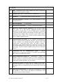
EUROPEAN COMMISSION JOINT RESEARCH CENTRE Institute for Energy and Transport Energy Security Unit Ref. Ares(2014)3134831 - 24/09/2014 ANNEX I NL-Petten: "Supply, installation and maintenance of a 75kW/150kWh battery storage system for grid connected and island operation at the JRC-IET." JRC/PTT/2014/F.3/0088/OC OJ: 2014/S 183-322139 of 12/09/2014 - Technical Specifications - 1. INTRODUCTION The Institute for Energy and Transport (IET) is one of the seven institutes of the Joint Research Centre, which is a directorate-general of the European Commission. IET is based both in Petten (the Netherlands) and Ispra (Italy) and has a multidisciplinary team of more than 300 academic, technical and support staff members. The mission of IET is to provide support to EU policies to ensure sustainable, safe, secure and efficient energy production, distribution and use, and to foster sustainable and efficient transport. One of the IET units that are based in Petten is dedicated to energy security (ESU). A research project set up within this unit is devoted to studies on smart electricity systems and interoperability (SESI), including so-called smart grids. Besides being more intelligent, efficient, quality-focused and resilient than current networks, smart grids are expected to better integrate renewable energy sources (RES), which is required for meeting the EU “20-20-20” targets. Increased penetration of RES in electricity networks results in growing power production variability. Hence reliable balancing technologies are required a/ to provide extra power when RES power production is too low and b/ to store energy when there is a surplus of produced RES power. This balancing task can be provided by energy storage technologies, not only in transmission and distribution grids but also in smaller-scale networks. The requested battery storage system must allow carrying out a variety of experiments in this field. 2. SCOPE The scope of the contract is the supply, installation and maintenance of a battery storage system for grid connected operation and island operation, with the following general characteristics: Storage power/capacity: 75 kW and 150 kWh Lithium-ion battery Expected use: 1 daily charge/discharge cycle The whole system must be fully operational after it is connected to the existing JRC AC grid (Plug & play) Local and remote control Bi-directional 4 quadrant power converter AC circuit breakers and protection DC circuit breakers and protection Main isolation transformer Auxiliary power distribution circuit Metering on AC and DC side Integration in a standard 20 foot outdoor container Able to operate grid connected and off-grid User's manual and software in English TS - JRC/PTT/2014/F.3/0088/OC p. 2/9 3. MANDATORY TECHNICAL REQUIREMENT The equipment shall meet all of the mandatory technical requirements given below. In view of this, the tenderer shall reproduce the following table in his offer, indicate compliance, yes or no, and add further comments where deemed necessary as to allow complete evaluation of conformity of the equipment with the mandatory technical requirements mentioned in this table. TABLE 1: Equipment and mandatory requirements Compliance (yes/no) Further comments … A. Battery A1 Chemistry: Lithium ion A2 Maximum voltage: < 1000 Vdc A3 Minimum storage system capacity available on the AC grid side (discharge rate C/2, discharge in 2 hours): 150 kWh A4 DC breaker and protection (compliant with EN 50272-2:2001 or equivalent) B. Power converter B1 Grid-tie and off-grid operation B2 3-phase, 0.4 kV, 50 Hz B3 Continuous power (at 25°C ambient temperature): 75 kW B4 4 quadrant operation for apparent power B5 Supervision of battery charging and discharging (power limitation depending on state of charge, coordinated action with battery EMS, protection against overcharge, protection against full discharge). B6 Efficiency: > 90% (from 25% to 100% of rated power). The efficiency curve (at power factor=1) shall be provided in the offer. B7 Ramping capacity (P and Q): 0-100% in less than 1 second B8 AC breaker and protection (compliant with Dutch standard NEN1010 or equivalent) TS - JRC/PTT/2014/F.3/0088/OC p. 3/9 B9 Isolation transformer between JRC AC grid and the DC source (battery) B10 P and Q dynamically settable in grid-tie operation B11 Continuous VAr capability is higher than 50 kVA C. Monitoring and control C1 Local on-device user interface (screen size >= 5 inch) C2 Remote control capability (SCADA): MODbus/TCP C3 Control Signals: select operation mode, specify set-points (P, Q, cosphi), switch on/off battery, switch on/off converter, Disconnect from grid, synchronize to grid C4 Monitoring signals: Ugrid, fgrid, Pconv, Qconv, converter state, SOC,Vbat, Ibat, Ibatmax, battery state, alarms, AC measurement on all phases. C5 Dynamic active power control (P): in grid-tie operation, the active power is specified according to a set-point sent by the GUI or the SCADA. The transition time between two set-point values shall be less than 1 second. C6 Dynamic reactive power control (Q): in grid-tie operation, the reactive power shall be specified according to a set-point sent by the GUI or the SCADA. The transition time between two setpoint values should be less than 1 second. C7 Island Operation capability: the island operation shall allow fixed frequency and voltage operation. The value of frequency and voltage can be changed through the GUI or the SCADA C8 Low voltage ride through (LVRT). The LVRT parameters shall be adaptable in order to suit the requirements of Distributed Generation systems in the different European countries. The available settings for the LVRT parameters shall be provided in the offer. C9 User's Manual provided in English language C10 All software needed for the operation of the system shall be provided in English and in the latest versions available at the time of the system commissioning and must include any required licenses without time limitations. TS - JRC/PTT/2014/F.3/0088/OC p. 4/9 D. Container D1 Size: Standard 20 foot; with a suitable floor able to support the (supplied) battery system weight. D2 Outside door: Min 875/2000 mm with cylinder lock D3 Windows: D4 Thermal insulation: minimum 5 cm foam insulation on wall, ceiling and floor D5 Internal lighting: D6 Internal electrical plugs: D7 Electrical cabinet internal appliances: the electrical cabinet (3+1 phase, 16 A, 400 Vac) is supplying internal 1-phase appliances: the lights (phase 1), the AC plugs (phase 1 and phase 2), and the auxiliary supply of the battery converter (phase 3). An external power supply cable (not part of the offer) will be connected to the cabinet. The cabinet includes standard safety devices (RSD, automatic fuses) D8 Connection box AC cables: an AC busbar is located in a separate connection box inside the container. On the outside wall of the container, are installed European standard 125A CEE female plug + male plug with 5 poles. AC cables (3-phase, 5 conductors, with double isolation) are connected on one end to the internal busbar and on the other end to the external 125A CEE plugs. The box includes standard safety devices (automatic fuses). D9 Connection box for communication cables: a separate connection box inside the container is available for connecting the external communication cables. D10 Inside temperature control: the temperature inside the container must be controlled (ideally by forced ventilation) to allow continuous operation of the converter at nominal power with closed window and door, all year round D11 Openings for cables: openings shall be available for the power AC, the container power supply and the communication cables. Openings must be available both in the lateral walls and in the floor. D12 Opening for maintenance: if required for maintenance, it must be possible to easily remove the different components of the storage system out of the container. 1x aluminium sliding window with lock TS - JRC/PTT/2014/F.3/0088/OC 2x fluorescent 4x 16A, 230Vac on the walls p. 5/9 D13 Painting: the inside and outside surfaces of the container must be painted in white colour. D14 Mobility: the equipment inside the container shall be well fixed to allow standard international transportation after the system commissioning. E. Environment E1 Min outdoor temp -20°C Max outdoor temp 40°C E2 Cooling power electronics: Fan forced ventilation shall be provided and shall be sufficient up to 20°C outdoor temperature. In addition, in case of higher outdoor temperatures (up to 40°C) , an air-conditioning unit shall be available for cooling. E3 Humidity: E4 Noise: < 85 dBA @ 2m E5 Enclosure: E6 Enclosure: IP rating IP23 < 95% non-condensing Outdoor container F. Standards compliance and warranty F1 CE Marking F2 Safety: IEC 62103 – Electronic equipment for use in power installations F3 EMC: IEC 61000-3-4, IEC 61000-3-5 F4 Warranty: 4. 2 years CONTRACTUAL STAGES Stage 1 Stage 1a: supply and installation. Supply and installation of the equipment shall be completed in no longer than three (3) months after the contract’s entry into force. The container shall be installed on a parking place of JRC-IET institute. The cabling work for connecting the container to the JRC grid will be organized by JRC. TS - JRC/PTT/2014/F.3/0088/OC p. 6/9 Stage 1b: commissioning It shall include testing of all functions and capabilities of the installed equipment at all modes of operation and should be executed no later than two (2) months after the end of stage 1a. During the commissioning, the different functions and performance of the storage system shall be demonstrated by the contractor after JRC has connected the storage system to its grid. The costs for the commissioning tests must be included in this offer. During the commissioning, the following functions shall be tested: Battery cycling test. During the test, the storage system is connected to the low voltage grid of the JRC. Starting with a fully charged battery (SOC >99%), the storage system is discharged by injecting a constant AC Power of 75 kW in the JRC grid during 2 hours. This first phase shall be successful if the storage system is able to inject 150 kWh in the JRC grid. In a second phase, the battery is recharged with an AC power of 75 kW until the battery is fully charged (SOC >99%). The end of charge and discharge, the change of maximum currents must be automatically supervised by the storage system controller. During this test, the efficiency of the converter will also be recorded. The local and remote control and monitoring (GUI and SCADA) shall be tested. Grid connected (parallel) operation: test of the available dynamic active power control (P) functions (fixed setpoint, function of frequency and state of charge, schedule), test of the available dynamic reactive power control (Q) functions (fixed setpoint, function Q(U), function G(P)) Island operation: test on a variable load profile and on a variable generation profile The commissioning is subject to a well-documented technical report (in English) prepared and signed by the Contractor and upon approval countersigned by Commission staff. In case of a negative test result, the Contractor shall on his own costs take any necessary measures to successfully pass a second commissioning test. In case of a positive test result, the Commission shall sign the Certificate of Conformity (Annex III to the contract). Notwithstanding the completion of training, the date of signature of this annex shall be considered the start of Stage 2 - warranty. Stage 1c: training At the request of the Commission, subject to explicit release by the Commission of that sub-stage, the Contractor shall give minimum 2 working days of operational training on the equipment to staff of the Commission (up to 5 persons) at the Commission premises. The exact dates of the training sessions have to be arranged upon mutual agreement among the parties, but shall be provided at the latest within 15 working days upon request. The training shall be given in English. The main content of the training shall be: Overview of storage system components Safety aspects TS - JRC/PTT/2014/F.3/0088/OC p. 7/9 Operation of the storage system in grid connected mode (functions, parameters) Operation of the storage system in island mode(functions, parameters) Transition between island and grid connected modes(functions, parameters) Remote control and monitoring Maintenance issues Stage 2: Warranty including maintenance The warranty, which shall include preventive maintenance services (the latter to be performed as described below under stage 3a) of at least 24 months, shall start after signature of the Certificate of Conformity (Annex III) by the JRC-IET related to substage 1b. The equipment shall be covered by at least 24 months warranty against all hidden defects in manufacture, materials or components. Performance of the equipment must be continuous and must comply with the specified requirements for the entire warranty period. In particular, it is expected that the storage capacity does not drop below the requirements because of battery aging. Preventive maintenance shall take place at least once a year and shall include the control of the equipment's performance, its calibration and replacement of any defective part or component thereof at the expense of the Contractor. During the warranty period, the Contractor shall, upon unsatisfactory equipment performance or in case the equipment cannot be operated safely respond to a maintenance request of the Commission’s technical responsible (or his deputy) not later than two (2) working days as of the date of the Commission’s request by giving technical assistance using appropriate means of communication (e.g. by phone or e-mail). If necessary, technical competent personnel of the Contractor – shall be on site not later than five (5) working days as of the date of such request by the Commission. Stage 3: Maintenance Without prejudice to contract clauses, the duration of the preventive and corrective maintenance shall be equal to 12 months, as of the date of release by the Commission of this stage. The maintenance is automatically extended two (2) times of same duration and scope following expiry of the previous period. Maintenance intervention(s) shall in principle take place at the Commission premises in Petten during normal working hours (Monday-Friday, 08.30 hrs to 17.00 hrs, excluding holidays) upon mutual agreement among both parties on the schedule and shall be performed by technical staff of the Contractor who will have free access to the equipment to be maintained. The technical staff of the Commission will be present during on-site maintenance. When deemed necessary and by mutual agreement of both parties, offsite intervention(s) at the sole expense of the Contractor (including shipment) may take place. TS - JRC/PTT/2014/F.3/0088/OC p. 8/9 Sub-Stage 3a: Preventive maintenance Without prejudice to contract clauses, preventive maintenance shall mean the periodic intervention by the Contractor to the Equipment to ensure satisfactory Equipment performance and shall include: Onsite visit(s) at least once every 12 months or according to the periodicity defined by the manufacturer(s) and the manual(s) of the components of the equipment. Check of proper functioning of all components of the equipment including related minor repairs. Any software updates if needed for improving the performance of the equipment. The interventions shall be made in agreement with the Commission. Preventive maintenance shall take place at the premises of the Commission unless otherwise mutually agreed. Sub-stage 3b: Corrective maintenance Without prejudice to contract clauses, corrective maintenance shall mean in addition to preventive maintenance any intervention by the Contractor upon an explicit request by the Commission in case of improper performance or breakdown of any of the equipment or its functionalities or its upgrading to re-establish its satisfactory performance. The costs will be in accordance with the actual performed hours and spare parts/consumables used and following the prices as per Annex II (Tenderer's offer) for the hourly rate and travelling costs. The spare parts/consumables to be used shall be subject to prior approval by the use of an order form (as per Annex VI of the contract). The contractor shall provide an offer for the required material and the order shall be signed by the Commission before the corrective maintenance takes place. Each intervention shall principally be resolved within 10 consecutive working days after reception of the request and/or order form. This period may be extended by the Commission upon a duly substantiated prolongation request by the Contractor. TS - JRC/PTT/2014/F.3/0088/OC p. 9/9