1
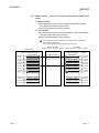
Type Q80BD-J61BT11N/Q81BD-J61BT11
CC-Link System Master/Local Interface Board
User's Manual (For SW1DNC-CCBD2-B)
-Q80BD-J61BT11N
-Q81BD-J61BT11
SAFETY PRECAUTIONS
(Be sure to read these instructions before using the product.)
Before using this product, read this manual and the relevant manuals introduced in this manual carefully
and handle the product correctly with full attention to safety.
Note that these precautions apply only to this product. Refer to the user's manual of the CPU module for
safety precautions on programmable controller systems.
In this manual, the safety instructions are ranked as "
WARNING " and " CAUTION".
WARNING
Indicates that incorrect handling may cause hazardous conditions,
resulting in death or severe injury.
CAUTION
Indicates that incorrect handling may cause hazardous conditions,
resulting in minor or moderate injury or property damage.
Note that failure to observe the ! CAUTION level instructions may also lead to serious results
depending on the circumstances.
Be sure to observe the instructions of both levels to ensure personal safety.
Please keep this manual in accessible place and be sure to forward it to the end user.
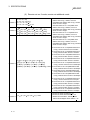
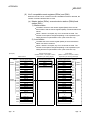
[DESIGN PRECAUTIONS]
!
WARNING
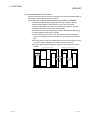
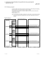
For details on the operating status of each station when a communication problem occurs in the
data link, refer to Section 6.5 of this manual.
If a cable dedicated to the CC-Link is disconnected, this may destabilize the line, and a data link
communication error may occur in multiple stations. Make sure to create an interlock circuit in
the sequence program so that the system will operate safely even if the above error occurs.
Failure to do so may result in a serous accident due to faulty output or malfunctions.
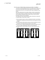
When performing the control of the personal computer in operation (changing data), configure
an interlock circuit in a user program so the safety of the overall system is always maintained.
When performing other controls of the personal computer in operation (changing program and
operation status (status control)), read this manual carefully and confirm if the overall safety is
maintained.
Especially, when this control is performed to a remote personal computer from an external
device, problems that have occurred on the personal computer side may not be able to
immediately be handled if there is a data communication error.
Define a troubleshooting agreement between external devices and the personal computer for
data communication error occurrences, as well as construct an interlock circuit in the user
program.
Do not write any data from the user program into the "system area" of the board buffer memory.
Writing data into the "system area" may cause a CC-Link system malfunction.
A failure in the board may cause remote I/O not to turn on or off correctly.
For critical I/O signals that may cause a serious accident, establish a circuit to externally monitor
them.
A-1
A-1
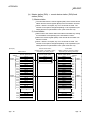
[DESIGN PRECAUTIONS]
!
CAUTION
Do not bunch the control wires or communication cables with the main circuit or power wires, or
install them close to each other.
They should be installed 100mm (3.94 in.) or more from each other.
Not doing so could result in noise that may cause malfunction.
[INSTALLATION PRECAUTIONS]
!
CAUTION
Use the board in an environment that meets the general specifications contained in this user's
manual.
Using this board in an environment outside the range of the general specifications may cause
electric shock, fire, malfunction, and damage to or deterioration of the product.
Do not directly touch the conductive area or electronic components of the board.
Doing so may cause malfunction or failure in the board.
Fix the board by tighten the board-fixing screws within the specified torque range.
Under tightening may cause drop of the component or wire, short circuit, or malfunction.
Over tightening may damage the screw and/or module, resulting in drop, short circuit, or
malfunction.
For the tightening torque of the board fixing screws, refer to the manual supplied with the
personal computer.
Always make sure to touch the grounded metal to discharge the electricity charged in the body,
etc., before touching the board.
Failure to do so may cause a failure or malfunctions of the board.
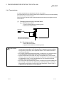
Be sure to shut off all phases of the external power supply used by the system before installing
or removing the board. If all power is not turned off, not doing so may cause damage to the
product.
Install the board to a personal computer which is compliant with PCI standard or PCI Express
standard (Section 2.3). Failure to do so may cause a failure or malfunction.
Securely mount the board to the PCI slot of the mounting device.
If the board is not mounted correctly, this may lead to malfunctioning, failure or cause the board
to fall.
When mounting the board, take care not to become injured by the components that are installed
or surrounding materials.
When installing the board, take care not to contact with other boards.
While handling the board, be sure to keep it free of static electricity.
Static electric charges may damage the board or result in malfunction.
Be sure to turn off the power supply to the applicable station before installing or removing the
terminal block.
If the terminal block is installed or removed without turning off the power supply to the applicable
station, correct data transmission cannot be guaranteed.
R
A-2
A-2
[INSTALLATION PRECAUTIONS]
!
CAUTION
Do not drop the board and the terminal block or subject it to any excessive shock.
It may damage the board and the terminal block or result in malfunction.
[WIRING PRECAUTIONS]
!
CAUTION
Be sure to shut off all phases of the external power supply used by the system before installing
or removing the board and wiring.
Not doing so may cause damage to the product.
When turning on the power and operating the module after installation and wiring, always attach
the computer's main cover.
Failure to do so may cause an electric shock.
When turning on the power and operating the module after wiring is completed, always attach
the terminal cover that comes with the product.
There is a risk of malfunction if the terminal cover is not attached.
Always ground the SLD terminal of the board and the personal computer to the protective
ground conductor.
Not doing so can cause a malfunction.
Tighten the terminal screws within the range of specified torque.
If the terminal screws are loose, it may cause short circuits or malfunction.
If the terminal screws are tightened too much, it may cause damage to the screw and/or the
board, resulting in short circuits or malfunction.
Prevent foreign matter such as swarf or wire chips from being attached onto the board.
Failure to do so may cause fires, failure or malfunction.
Be sure to fix the wires or cables connected to the board by placing them in a duct or clamping
them.
If not fixed, cables may be dangled and accidentally pulled, causing damage to the board and
cables and malfunction due to bad cable contacts.
Do not install the control lines together with the communication cables, or bring them close to
each other. Doing so may cause malfunctions due to noise.
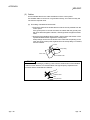
When removing the communication cable or power supply cables from the board, do not pull the
cable.
First loosen the screws where the cable is connected to the board and then remove the cable.
Pulling the cable that is connected to the board may cause damage to the board and cable or
malfunction due to bad cable contacts.
Solderless terminals with insulation sleeve cannot be used for the terminal block. It is
recommended that the wiring connecting sections of the solderless terminals will be covered
with a marking tube or an insulation tube.
Be sure to turn off the power supply to the applicable station before installing or removing the
terminal block.
If the terminal block is installed or removed without turning off the power supply to the applicable
station, correct data transmission cannot be guaranteed.
A-3
A-3
[WIRING PRECAUTIONS]
!
CAUTION
Always make sure to power off the system in advance when removing the terminating resistor to
charge the system. If the terminating resistor is removed and mounted while the system is
energized, normal data transmission will not be guaranteed.
Use applicable solderless terminals and tighten them with the specified torque.
If any solderless spade terminal is used, it may be disconnected when the terminal screw comes
loose, resulting in failure.
Be sure to tighten any unused terminal screws within a tightening torque range (0.66 to 0.89N.m).
Failure to do so may cause a short circuit due to contact with a solderless terminal.
[START UP AND MAINTENANCE PRECAUTIONS]
!
CAUTION
Do not dismantle or rebuild the board.
Doing so could cause failure, malfunction, injury or fire.
Be sure to shut off all phases of the external power supply used by the system before installing
or removing the board.
Not doing so may cause failure or malfunction of the board.
Do not touch the terminal while the power is on.
Doing so may cause malfunction.
Be sure to shut off all phases of the external power supply used by the system before cleaning
or retightening the terminal screws or module mounting screws.
Not doing so may cause damage to the product.
Fix the board by tighten the board-fixing screws within the specified torque range.
Under tightening may cause drop of the component or wire, short circuit, or malfunction.
Over tightening may damage the screw and/or module, resulting in drop, short circuit, or
malfunction.
For the tightening torque of the board fixing screws, refer to the manual supplied with the
personal computer.
Always make sure to touch the grounded metal to discharge the electricity charged in the body,
etc., before touching the board.
Failure to do so may cause a failure or malfunctions of the board.
[DISPOSAL PRECAUTIONS]
!
CAUTION
When disposing of this product, treat it as industrial waste.
A-4
A-4
CONDITIONS OF USE FOR THE PRODUCT
(1) Mitsubishi programmable controller ("the PRODUCT") shall be used in conditions;
i) where any problem, fault or failure occurring in the PRODUCT, if any, shall not lead to any major or
serious accident; and
ii) where the backup and fail-safe function are systematically or automatically provided outside of the
PRODUCT for the case of any problem, fault or failure occurring in the PRODUCT.
(2) The PRODUCT has been designed and manufactured for the purpose of being used in general
industries.
MITSUBISHI SHALL HAVE NO RESPONSIBILITY OR LIABILITY (INCLUDING, BUT NOT LIMITED
TO ANY AND ALL RESPONSIBILITY OR LIABILITY BASED ON CONTRACT, WARRANTY, TORT,
PRODUCT LIABILITY) FOR ANY INJURY OR DEATH TO PERSONS OR LOSS OR DAMAGE TO
PROPERTY CAUSED BY the PRODUCT THAT ARE OPERATED OR USED IN APPLICATION
NOT INTENDED OR EXCLUDED BY INSTRUCTIONS, PRECAUTIONS, OR WARNING
CONTAINED IN MITSUBISHI'S USER, INSTRUCTION AND/OR SAFETY MANUALS, TECHNICAL
BULLETINS AND GUIDELINES FOR the PRODUCT.
("Prohibited Application")
Prohibited Applications include, but not limited to, the use of the PRODUCT in;
Nuclear Power Plants and any other power plants operated by Power companies, and/or any other
cases in which the public could be affected if any problem or fault occurs in the PRODUCT.
Railway companies or Public service purposes, and/or any other cases in which establishment of a
special quality assurance system is required by the Purchaser or End User.
Aircraft or Aerospace, Medical applications, Train equipment, transport equipment such as Elevator
and Escalator, Incineration and Fuel devices, Vehicles, Manned transportation, Equipment for
Recreation and Amusement, and Safety devices, handling of Nuclear or Hazardous Materials or
Chemicals, Mining and Drilling, and/or other applications where there is a significant risk of injury to
the public or property.
Notwithstanding the above, restrictions Mitsubishi may in its sole discretion, authorize use of the
PRODUCT in one or more of the Prohibited Applications, provided that the usage of the PRODUCT is
limited only for the specific applications agreed to by Mitsubishi and provided further that no special
quality assurance or fail-safe, redundant or other safety features which exceed the general
specifications of the PRODUCTs are required. For details, please contact the Mitsubishi
representative in your region.
A-5
A-5
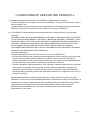
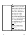
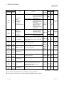
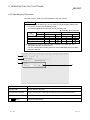
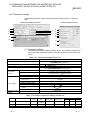
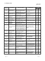
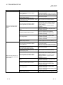
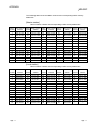
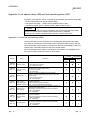
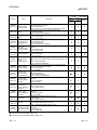
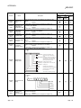
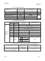
REVISIONS
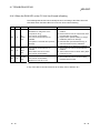
The manual number is written at the bottom left of the back cover.
Print date
Manual number
Revision
Jun., 2005
SH (NA)-080527ENG-A First Printing
Nov., 2005
SH (NA)-080527ENG-B
Correction
Section 2.2.1, Section 8.4.1, Section 8.4.3, Chapter 9,
Section 17.1.1
Jun., 2006
SH (NA)-080527ENG-C
Correction
Section 2.2.4, Section 3.2, Section 8.6, Section 17.2.1
Mar., 2007
SH (NA)-080527ENG-D
Correction
Generic Terms and Abbreviations, Section 2.2.1, Section 8.4.1,
Section 10.1.2, Section 11.2, Section 11.4, Section 11.8
Addition
Section 11.3.5, Section 11.3.6, Section 11.7
Oct., 2007
SH (NA)-080527ENG-E
Correction
Generic Terms and Abbreviations, Section 1.1,
Section 1.3, Section 2.2.1, Section 4.2.3, Chapter 7,
Section 8.4.1, Section 9.1, Section 11.3, Section 17.1.4,
Section 17.2.1, Section 17.3.1, Appendix 3.2,
Section 8.4.2 to Section 8.4.3 → Section 8.4.3 to Section 8.4.4
Addition
Section 8.4.2, Appendix 7
Jan., 2008
SH (NA)-080527ENG-F
Correction
Precautions for use,
Generic Terms and Abbreviations, Chapter 1, Section 2.2,
Section 2.2.1, Section 2.2.3, Section 3.1, Section 4.2.1,
Section 4.2.2, Section 4.2.3, Section 4.2.4, Section 4.4.5,
Section 5.2, Section 5.2.2, Section 5.2.3, Section 5.2.4,
Section 5.3, Section 5.3.1, Section 5.3.2, Section 6.1,
Section 7.1.1, Section 7.1.2, Section 8.2.1, Section 8.2.2,
Section 8.4.1, Section 8.6, Section 9.3.6, Section 9.3.7,
Section 9.3.8, Section 9.3.11, Section 10.1.1, Section 10.1.2,
Section 12.2.1, Section 12.5.1, Section 13.1.2, Section 13.2.2,
Section 14.1.2, Section 14.2.2, Section 15.2.1, Section 16.2.1,
Section 17.1.4, Section 17.2.1, Section 17.6, Appendix 3.1.2,
Appendix 3.1.3
A-6
A-6
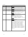
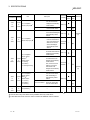
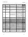
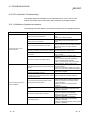
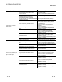
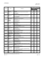
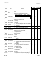
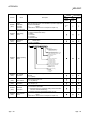
The manual number is written at the bottom left of the back cover.
Print date
May, 2008
Manual number
SH (NA)-080527ENG-G
Revision
Model addition
Q81BD-J61BT11
Correction
Precautions for use, Generic Terms and Abbreviations,
Product List, Section 1.1, Section 1.3, Section 2.1, Section 2.2.1,
Section 2.2.2, Section 2.2.3, Section 2.2.4, Section 3.1,
Section 3.2, Section 4.4.7, Section 5.2, Section 8.3,
Section 8.4.1, Section 8.4.3, Section 8.4.4, Section 8.6,
Section 8.7.2, Section 9.1.1, Section 10.1.2, Section 11.3,
Section 12.1, Section 12.5.2, Section 13.1.1, Section 13.1.5,
Section 13.2.1, Section 13.2.5,Section 14.1.1, Section 14.1.5,
Section 14.2.1, Section 14.2.5,Section 15.1, Section 15.5.2,
Section 16.1, Section 16.5.2, Section 17.1.3, Section 17.3.1,
Section 17.3.2, Appendix 1.1,Appendix 1.2, Appendix 2.3,
Appendix 3, Appendix 3.2
Addition
Appendix 8.1, Appendix 8.2
Sep., 2008
SH (NA)-080527ENG-H
Correction
Section 3.2
Oct., 2008
SH (NA)-080527ENG-I
Correction
Generic Terms and Abbreviations, Section 3.3, Section 10.1.2
Jul., 2009
SH (NA)-080527ENG-J
Correction
Chapter 7, Appendix 7,1, Appendix 8.1, Appendix 8.2
Oct., 2009
SH (NA)-080527ENG-K
Correction
Section 2.2.1, Section 8.4.1,
Section 10.1.2, Section 11.4, Section 17.1.1, Section 17.2.1,
Section 17.3.1, Appendix 4.1, Appendix 4.2
May, 2010
SH (NA)-080527ENG-L
Correction
SAFETY PRECAUTIONS, Generic Terms and Abbreviations,
Section 1.1, Section 2.2.1, Section 3.1, Section 8.2.1,
Section 8.3, Section 8.4, Section 8.6, Section 10.2.1,
Section 11.3.3, Section 11.3.4, Section 11.9, Appendix 7,
Section 1.3 → Appendix 8,
Appendix 8 to Appendix 9 → Appendix 9 to Appendix 10
Addition
CONDITIONS OF USE FOR THE PRODUCT
Deletion
Section 11.3.5, Section 11.3.6
A-7
A-7
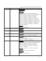
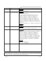
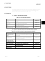
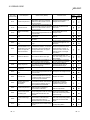
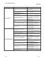
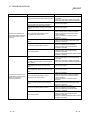
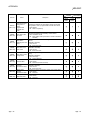
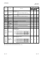
The manual number is written at the bottom left of the back cover.
Print date
Dec., 2010
Manual number
SH (NA)-080527ENG-M
Revision
Correction
Section 2.2.1
May, 2011
SH (NA)-080527ENG-N
Correction
Precautions for use, Manuals, Product List, Appendix 2.3,
Appendix 7.2
Mar., 2012
SH (NA)-080527ENG-O
Correction
Section 2.2.1, Section 8.4.1, Section 8.4.2
Appendix 10 changed to Appendix 12
Addition
Appendix 10, Appendix 11
Apr., 2012
SH (NA)-080527ENG-P
Correction
SAFETY PRECAUTIONS, Manuals,
How to Read this Manual, Generic Terms and Abbreviations,
Product List, Section 1.1, Section 2.2.1, Section 3.1,
Section 4.4.7, Section 7.2.1, Section 7.4.1, Section 7.4.2,
Section 8.1.1, Section 8.1.7, Section 8.3.3, Section 8.3.5,
Section 8.3.6, Section 8.3.7, Section 8.3.8, Chapter 9,
Section 9.2, Section 10.5.2, Section 11.1.5, Section 11.2.5,
Section 12.2.5, Section 13.5.2, Section 14.5.2, Section 15.1.1,
Section 15.1.4, Section 15.2.1, Section 15.3.5, Appendix 1.1,
Appendix 3.1.4, Appendix 7.1, Appendix 8, Appendix 10,
Appendix 12.1
Chapter 7 → Appendix 10,
Chapter 8 to Chapter 9 → Chapter 7 to Chapter 8,
Chapter 11 to Chapter 17 → Chapter 9 to Chapter 15,
Appendix 9 to Appendix 12 → Appendix 11 to Appendix 14
Addition
Appendix 9
Deletion
Chapter 10, Section 11.3 to Section 11.9
Dec., 2012
SH (NA)-080527ENG-Q
Correction
HOW TO USE THIS MANUAL, GENERIC TERMS AND
ABBREVIATIONS, Section 7.7.2
A-8
A-8
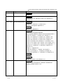
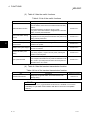
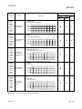
The manual number is written at the bottom left of the back cover.
Print date
Sep., 2013
Manual number
SH (NA)-080527ENG-R
Revision
Correction
SAFETY PRECAUTIONS, MANUALS, HOW TO USE THIS
MANUAL, GENERIC TERMS AND ABBREVIATIONS,
Section 1.1, Section 2.1, Section 2.3, Section 3.2.1, Section 3.4,
Section , Section 4.3.4, Section 4.4.5, Chapter 5, Section 5.1 to 5.6,
Section 6.1, Section 6.2.1, Section 6.2.2, Section 6.3.1, Section 6.3.2,
Section 6.4.1, Section 6.4.2, Section Chapter 7, Section 7.1 to 7.3,
Section 8.1 to 8.3, Section 9.1, Section 9.2, Section 10.2.1,
Section 10.2.2, Section 10.5.1, Section 11.1.2, Section 11.2.2,
Section 12.1.2, Section 12.1.3, Section 12.2.2, Section 12.2.3,
Section 13.2.1, Section 13.2.2, Section 14.2.1, Section 14.2.2,
Chapter 15, Chapter 16, Section 16.1 to 16.6, Section 2.1 changed 3.2.1,
Section 2.2.1 changed 2.3, Section 2.2.2 changed 2.2,
Chapter 7 changed Chapter 5, Section 5.2 changed 5.3,
Section 7.7 changed 5.4.4, Section 7.8.1 changed 5.5,
Section 7.8.2 changed 5.6, Section 7.4 changed Chapter 7,
Section 7.4.1 changed 7.1, 16.2.3, Section 7.4.2 changed 7.3,
Section 8.1.7 changed Appendix 10, Section 15.3.5 changed Chapter 15,
Chapter 15 changed 16, Section 15.1.1 changed 16.1,
Section 15.1.4 changed 16.3.2, Section 15.1.2 changed 16.4.3,
Section 15.3, 15.3.1, 15.3.2 changed 16.5, Section 15.6 changed 16.6,
Appendix 4, 4.1 changed 3.4, Section 2.2.4 changed Appendix 11,
Appendix 4.2 changed 1, Section15.3.3 changed Appendix 2.1,
Section 15.3.4 changed Appendix 2.2, Chapter 5 changed Appendix 3,
Appendix 6 changed 4, Appendix 1 to 3 changed Appendix 5 to 7,
Appendix 14 changed 8, Appendix 8 changed 9, Appendix 9 changed 10,
Appendix 5 changed 12, Appendix 7 changed 15, Appendix 12 changed 16,
Appendix 13 changed 17, Appendix 10 changed 18,
Appendix 11 changed 19
Addition
Section 5.3.3, Section 5.3.4, Section 5.4.3, Section 5.7, Section 6.5,
Chapter 16, Section 16.2, Section 16.2.1, Section 16.2.2,
Section 16.3, Section 16.3.3, Section 16.4, Section 16.4.1,
Section 16.4.2, Appendix 13, Appendix 13.1, Appendix 13.2,
Appendix 14, Appendix 16.3
Deletion
Section 2.2.3, Section 5.2.1 to 5.2.4, Section 8.1.3 to 8.1.6,
Section 15.1, Section 15.1.3 Section 15.2, Section 15.2.1,
Section 15.3.3 to 15.3.5, Section 15.4, Section 15.5
A-9
A-9
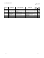
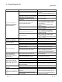
The manual number is written at the bottom left of the back cover.
Print date
Jan., 2014
Manual number
SH (NA)-080527ENG-S
Revision
Correction
Section 16.3.2, Appendix 2
Jun., 2014
SH (NA)-080527ENG-T
Correction
PRECAUTIONS FOR USE,
GENERIC TERMS AND ABBREVIATIONS, Section 2.2,
Section 2.3, Section 3.2.1, Section 4.3.4, Section 4.3.5,
Section 4.3.7, Section 7.1, Section 7.2, Section 8.1.1,
Section 8.2.8, Section 8.3.1, Section 8.3.2, Section 8.3.3,
Section 8.3.5, Section 8.3.6, Section 8.3.8, Section 8.3.10,
Section 16.1, Section 16.2.2, Section 16.2.3, Section 16.3.2,
Appendix 13.2, Appendix 15.2, Appendix 16.2, Appendix 16.3,
Appendix 17
Section 8.3.8 to Section 8.3.11 → Section 8.3.7 to Section 8.3.10
Deletion
Section 8.3.7
Apr., 2015
SH (NA)-080527ENG-U
Correction
Section 2.3, Section 3.4, Section 7.2, Section 16.3.2
Sep., 2015
SH (NA)-080527ENG-V
Correction
Section 1.1, Section 1.2, Section 2.3, Section 4.1, Section 4.3.4,
Section 4.3.5, Section 6.1, Section 6.2.1, Section 6.2.2,
Section 6.3.1, Section 6.3.2, Section 6.4.1, Section 6.4.2,
Section 7.1, Section 8.2.1, Section 8.2.2, Section 8.2.5,
Section 10.2.2, Section 11.1.2, Section 11.2.2, Section 12.1.2,
Section 12.1.3, Section 12.2.2, Section 12.2.3, Section 13.2.2,
Section 14.2.2, Section 16.1, Section 16.2.3, Appendix 3.2,
Appendix 5.2, Appendix 7.1.2, Appendix 7.2, Appendix 8.1,
Appendix 14
Addition
Section 4.3.6, Section 16.6
Section 16.6 → Section 16.7
Japanese Manual Version SH-080526-V
This manual confers no industrial property rights or any rights of any other kind, nor does it confer any patent
licenses. Mitsubishi Electric Corporation cannot be held responsible for any problems involving industrial property
rights which may occur as a result of using the contents noted in this manual.
2005 MITSUBISHI ELECTRIC CORPORATION
A - 10
A - 10
PRECAUTIONS FOR USE
(1) Restrictions for functions depending on the personal computer or
the operating system
There are some restrictions for the functions or supported versions depending
on the operating system or personal computer to be used. For the operating
environment, refer to Section 2.5.
(2) When using the CC-Link Ver.2 board as a standby master station
Refer to Section 2.2 for combinations of modules when using the CC-Link
Ver.2 board as a standby master station.
(3) When using the CC-Link Ver.2 board as a master station
When using the CC-Link Ver.2 board as a master station, any of local modules
cannot be used as a standby master station.
(4) Restrictions on the CC-Link Ver.2 board installation
Installing the CC-Link Ver.2 board and CC-Link Ver.1 board to the same
computer and using both of them is not allowed.
(5) Installation
When a CC-Link Ver.2 board is used on a personal computer in which
SWnDNF-CCLINK has been installed, uninstall SWnDNF-CCLINK first, then
install the SW1DNC-CCBD2-B that is provided with the CC-Link Ver.2 board.
(6) Driver installation and updating
Do not install or update the driver other than the way written in the
troubleshooting in this manual.
The consistency between the driver and utility cannot be identified, and CCLink Ver.2 board may not operate properly.
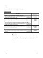
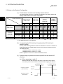
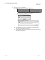
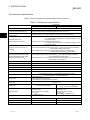
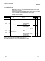
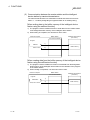
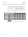
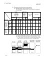
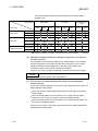
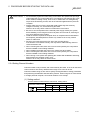
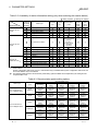
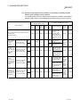
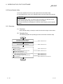
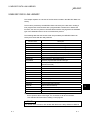
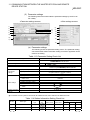
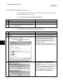
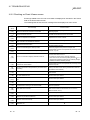
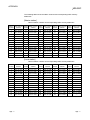
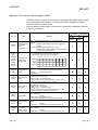
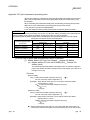
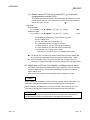
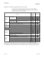
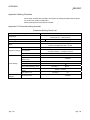
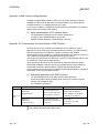
(7) Software versions of the CC-Link system master and local modules
When reading/writing data from/to other stations using the transient
transmission function in the CC-Link system, there is the restriction for the
software version for the CC-Link master and local modules in the following
table.
Model name
Software version
Remark
Version N or later
Not accessible if the software
version is M or earlier.
AJ61QBT11
A1SJ61QBT11
AJ61BT11
A1SJ61BT11
(8) Transient transmission functions of the CC-Link board
Transient transmission is not allowed to slave station No.64 on the CC-Link
system.
(9) Performance
The system performance using the CC-Link Ver.2 board differs according to
the performance/loaded condition of the personal computer, the processing
contents of the application software, and the type of the interface board. Use
the product after reviewing the system configuration and processing contents of
the software in advance.
For details of the CC-Link Ver.2 board performance, refer to Appendix 3 DATA
LINK PROCESSING TIMES.
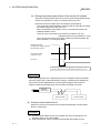
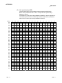
(10) Combination of ROM version and S/W version
When using CC-Link Ver.2 board ROM version 2B or later, use S/W package
version 1.06G or later.
A - 11
A - 11
INTRODUCTION
Thank you for purchasing the Type Q80BD-J61BT11N, Q81BD-J61BT11 CC-Link System Master/Local
Interface Board.
Please read this manual and related manuals thoroughly to fully understand the functions and performances
of the Type Q80BD-J61BT11N, Q81BD-J61BT11 CC-Link System Master/Local Interface Board in order to
use the product properly.
Please be sure to deliver this manual to the end users.
CONTENTS
SAFETY PRECAUTIONS .............................................................................................................................. A- 1
CONDITIONS OF USE FOR THE PRODUCT .............................................................................................A- 5
REVISIONS .................................................................................................................................................... A- 6
PRECAUTIONS FOR USE............................................................................................................................A-11
INTRODUCTION............................................................................................................................................A-12
CONTENTS....................................................................................................................................................A-12
MANUALS ......................................................................................................................................................A-19
HOW TO USE THIS MANUAL ......................................................................................................................A-20
GENERIC TERMS AND ABBREVIATIONS .................................................................................................A-21
PACKING LIST...............................................................................................................................................A-22
1 OVERVIEW
1- 1 to 1-10
1.1 Features of the CC-Link Ver.2 Board ..................................................................................................... 1- 2
1.2 Features of the CC-Link System ............................................................................................................ 1- 3
2 SYSTEM CONFIGURATION
2- 1 to 2- 8
2.1 System Configuration Using CC-Link Ver.2 Board ................................................................................ 2- 1
2.2 Notes on the System Configuration........................................................................................................ 2- 2
2.3 Operating Environment ........................................................................................................................... 2- 4
3 SPECIFICATIONS
3- 1 to 3-12
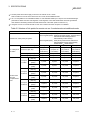
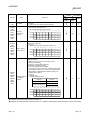
3.1 General Specifications ............................................................................................................................ 33.2 Performance Specifications .................................................................................................................... 33.2.1 Maximum number of connected modules ....................................................................................... 33.2.2 Maximum overall cable distance (for Ver.1.00) ............................................................................... 33.2.3 Maximum overall cable distance (for Ver.1.10) ............................................................................... 33.3 CC-Link Dedicated Cable Specifications ............................................................................................... 33.4 Buffer Memory List .................................................................................................................................. 34 FUNCTIONS
1
2
4
6
8
8
9
4- 1 to 4-54
4.1 Function List ............................................................................................................................................ 4- 1
4.2 Basic Functions ....................................................................................................................................... 4- 3
4.2.1 Communication with remote I/O stations ........................................................................................ 4- 3
4.2.2 Communication with the remote device stations ............................................................................ 4- 5
4.2.3 Communication with the local stations ............................................................................................ 4-10
4.2.4 Communication with the intelligent device station .......................................................................... 4-16
A - 12
A - 12
4.3 Functions for Improving System Reliability ............................................................................................ 4-22
4.3.1 Disconnecting a data link faulty station and continuing the data link with only normal stations
(slave station disconnect function) .................................................................................................. 4-22
4.3.2 Automatically reconnecting a disconnected data link faulty station when it returns to normal
(auto return function) ....................................................................................................................... 4-23
4.3.3 Retaining the device status of a data link faulty station
(setting the input data status from a data link faulty station) .......................................................... 4-24
4.3.4 Continuing the data link even when the master station is faulty (standby master function) .......... 4-25
4.3.5 Monitoring the operation of the software (operating system, driver) inside the hardware
(Driver WDT function) ..................................................................................................................... 4-35
4.3.6 Station-based block data assurance function ................................................................................. 4-36
4.4 Useful Functions ..................................................................................................................................... 4-40
4.4.1 Creating a program that contains modules to be added in the future
(reserved station function) ............................................................................................................... 4-40
4.4.2 Powering off a station in operation without detecting an error
(error invalid station setting function) .............................................................................................. 4-41
4.4.3 Checking operations for each station (data link stop/restart) ......................................................... 4-42
4.4.4 Station number duplicate check ...................................................................................................... 4-42
4.4.5 Multiple CPU system support .......................................................................................................... 4-43
4.4.6 Reducing the reserved points of the remote I/O stations (Remote I/O station points setting) ...... 4-44
4.4.7 Increasing the number of cyclic points (Remote net ver.2 mode, Remote net additional mode).. 4-45
4.5 Transient Transmission Functions ......................................................................................................... 4-54
4.5.1 Performing transient transmission (functions) ................................................................................. 4-54
5 PROCEDURE BEFORE STARTING THE DATA LINK
5- 1 to 5-16
5.1 Procedures Before Operating the CC-Link Ver.2 Board ....................................................................... 5- 1
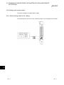
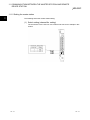
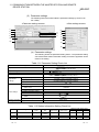
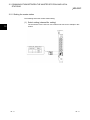
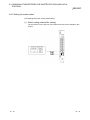
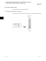
5.2 Component Names and Settings ........................................................................................................... 5- 2
5.3 Installation ............................................................................................................................................... 5- 4
5.3.1 Precautions on handling the CC-Link Ver.2 board ......................................................................... 5- 4
5.3.2 Installation environment ................................................................................................................... 5- 4
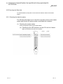
5.3.3 Board installation .............................................................................................................................. 5- 5
5.3.4 Setting Channel Numbers ................................................................................................................ 5- 6
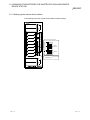
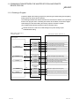
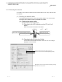
5.4 Wiring ...................................................................................................................................................... 5- 7
5.4.1 Preparation before wiring ................................................................................................................. 5- 7
5.4.2 Terminal block .................................................................................................................................. 5- 8
5.4.3 Wiring procedure .............................................................................................................................. 5-10
5.4.4 T-branch connection ........................................................................................................................ 5-12
5.5 Station Number Setting ........................................................................................................................... 5-14
5.6 Transmission Rate and Mode Settings .................................................................................................. 5-15
5.7 Test .......................................................................................................................................................... 5-15
6 PARAMETER SETTINGS
6- 1 to 6-12
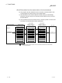
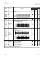
6.1 Parameter Setting Items ......................................................................................................................... 66.2 Parameter Setting Examples (Remote Net Ver.1 Mode) ...................................................................... 66.2.1 Master station network parameter settings ..................................................................................... 66.2.2 Local station network parameter settings ........................................................................................ 66.3 Parameter Setting Examples (Remote Net Ver.2 Mode) ...................................................................... 66.3.1 Master station network parameter settings ..................................................................................... 66.3.2 Local station network parameter settings ........................................................................................ 6A - 13
A - 13
1
5
5
6
7
7
8
6.4 Parameter Setting Examples (Remote Net Additional Mode) ............................................................... 6- 9
6.4.1 Master station network parameter settings ..................................................................................... 6- 9
6.4.2 Local station network parameter settings ........................................................................................ 6-10
6.5 Status Difference Between a Master Station and a Slave Station at an Error ..................................... 6-11
7 INSTALLING AND UNINSTALLING THE SOFTWARE PACKAGE
7- 1 to 7- 4
7.1 Installation and Uninstallation Precautions ............................................................................................ 7- 1
7.2 Installation ............................................................................................................................................... 7- 2
7.3 Uninstallation ........................................................................................................................................... 7- 4
8 OPERATING THE UTILITY SOFTWARE
8- 1 to 8-32
8.1 Starting and Ending Utility ...................................................................................................................... 8- 1
8.1.1 Starting a utility ................................................................................................................................. 8- 1
8.1.2 Quitting a utility ................................................................................................................................. 8- 2
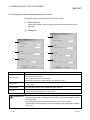
8.2 CC-Link Ver.2 Utility................................................................................................................................ 8- 3
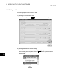
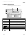
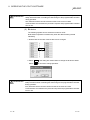
8.2.1 Screen configuration and basic operations ..................................................................................... 8- 3
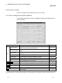
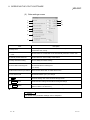
8.2.2 Operating the Board Information screen ......................................................................................... 8- 4
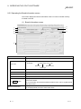
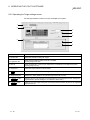
8.2.3 Operating the Other station monitor screen .................................................................................... 8- 7
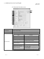
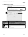
8.2.4 Operating the Online operation screen ........................................................................................... 8- 9
8.2.5 Operating the Parameter Settings screen ....................................................................................... 8-10
8.2.6 Operating the Target settings screen .............................................................................................. 8-12
8.2.7 Operating the Memory I/O test screen ............................................................................................ 8-13
8.2.8 Operating the Test screen ............................................................................................................... 8-14
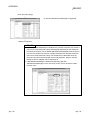
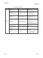
8.3 Device Monitor Utility .............................................................................................................................. 8-19
8.3.1 Overview ........................................................................................................................................... 8-19
8.3.2 Setting the batch monitoring ............................................................................................................ 8-21
8.3.3 Setting the 16-point register monitor ............................................................................................... 8-22
8.3.4 Setting the monitoring destination ................................................................................................... 8-23
8.3.5 Setting the device to be monitored .................................................................................................. 8-24
8.3.6 Changing word device/double word device values ......................................................................... 8-26
8.3.7 Switching a bit device on/off ............................................................................................................ 8-27
8.3.8 Switching Display Format ................................................................................................................ 8-28
8.3.9 Numerical pad .................................................................................................................................. 8-29
8.3.10 Other operations ............................................................................................................................ 8-30
9 MELSEC DATA LINK LIBRARY
10 COMMUNICATION BETWEEN THE MASTER STATION AND REMOTE I/O STATIONS
9- 1 to 9- 2
10- 1 to 10- 8
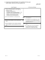
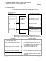
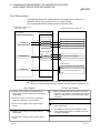
10.1 Configuring a System ......................................................................................................................... 1010.2 Setting up the master station .............................................................................................................. 1010.2.1 Switch setting (channel No. setting) ............................................................................................ 1010.2.2 Parameter settings ....................................................................................................................... 1010.3 Setting up the remote I/O stations ...................................................................................................... 1010.4 Creating a Program............................................................................................................................. 10-
A - 14
A - 14
1
2
2
3
4
5
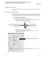
10.5 Executing the Data Link ...................................................................................................................... 1010.5.1 Checking the data link status ....................................................................................................... 10(1) Checking the master station................................................................................................... 10(2) Checking remote I/O stations. ................................................................................................ 1010.5.2 Confirming the operation with a user program ............................................................................ 10-
6
6
6
7
8
11 COMMUNICATION BETWEEN THE MASTER STATION AND REMOTE DEVICE STATION
11- 1 to 11-16
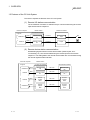
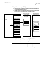
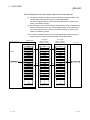
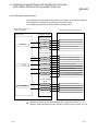
11.1 When Using the Remote Net Ver.1 Mode ......................................................................................... 11- 1
11.1.1 Configuring a System................................................................................................................... 11- 1
11.1.2 Setting the master station ............................................................................................................ 11- 2
(1) Switch setting (channel No. setting)....................................................................................... 11- 2
(2) Parameter settings ................................................................................................................. 11- 3
11.1.3 Setting up the remote device station ........................................................................................... 11- 4
11.1.4 Creating a Program ...................................................................................................................... 11- 5
11.1.5 Executing the data link ................................................................................................................. 11- 7
(1) Checking the data link status ................................................................................................. 11- 7
(2) Confirming the operation with a user program ...................................................................... 11- 9
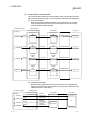
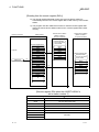
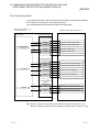
11.2 When Using the Remote Net Ver.2 Mode or Remote Net Additional Mode ..................................... 11-10
11.2.1 Configuring the system ................................................................................................................ 11-10
11.2.2 Setting the master station ............................................................................................................ 11-11
(1) Switch setting (channel No. setting)....................................................................................... 11-11
(2) Parameter settings ................................................................................................................. 11-12
11.2.3 Setting the remote device station ................................................................................................ 11-13
11.2.4 Creating a program ...................................................................................................................... 11-14
11.2.5 Executing the data link ................................................................................................................. 11-15
(1) Checking the data link status ................................................................................................. 11-15
(2) Confirming the operation with a user program ...................................................................... 11-16
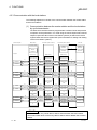
12 COMMUNICATION BETWEEN THE MASTER STATION AND LOCAL STATIONS
12- 1 to 12-16
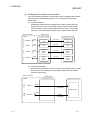
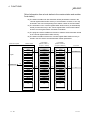
12.1 When Using the Remote Net Ver.1 Mode ......................................................................................... 1212.1.1 Configuring the system ................................................................................................................ 1212.1.2 Setting the master station ............................................................................................................ 12(1) Switch setting (channel No. setting)....................................................................................... 12(2) Parameter settings ................................................................................................................. 1212.1.3 Setting the local station ................................................................................................................ 12(1) Switch setting (channel No. setting)....................................................................................... 12(2) Parameter settings ................................................................................................................. 1212.1.4 Creating a program ...................................................................................................................... 1212.1.5 Executing the data link ................................................................................................................. 12(1) Checking the data link status ................................................................................................. 12(2) Confirming the operation with a user program ...................................................................... 12-
A - 15
A - 15
1
1
2
2
3
4
4
4
5
7
7
8
12.2 When Using the Remote Net Ver.2 Mode or Remote Net Additional Mode ..................................... 12- 9
12.2.1 Configuring the system ................................................................................................................ 12- 9
12.2.2 Setting the master station ............................................................................................................ 12-10
(1) Switch setting (channel No. setting)....................................................................................... 12-10
(2) Parameter settings ................................................................................................................. 12-11
12.2.3 Setting the local station ................................................................................................................ 12-12
(1) Switch setting (channel No. setting)....................................................................................... 12-12
(2) Parameter settings ................................................................................................................. 12-12
12.2.4 Creating a program ...................................................................................................................... 12-13
12.2.5 Executing the data link ................................................................................................................. 12-14
(1) Checking the data link status ................................................................................................. 12-14
(2) Confirming the operation with a user program ...................................................................... 12-14
13 COMMUNICATION BETWEEN THE MASTER STATION AND INTELLIGENT DEVICE STATION
(AJ65BT-R2)
13- 1 to 13-12
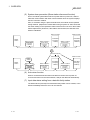
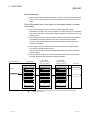
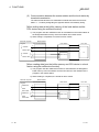
13.1 Configuring a System ......................................................................................................................... 13- 1
13.2 Setting the Master Station .................................................................................................................. 13- 2
13.2.1 Switch setting (channel No. setting) ............................................................................................ 13- 2
13.2.2 Parameter settings ....................................................................................................................... 13- 3
13.3 Setting up the intelligent device station .............................................................................................. 13- 4
13.4 Creating a Program............................................................................................................................. 13- 5
13.4.1 Initialization of the AJ65BT-R2 .................................................................................................... 13- 5
13.4.2 Data transmission ........................................................................................................................ 13- 7
13.4.3 Data reception .............................................................................................................................. 13- 8
13.5 Executing the Data Link ...................................................................................................................... 13- 9
13.5.1 Checking the data link status ....................................................................................................... 13- 9
13.5.2 Confirming the operation with a user program ............................................................................ 13-11
14 COMMUNICATION BETWEEN THE MASTER STATION AND INTELLIGENT DEVICE STATION
(AJ65BT-D75P2-S3)
14- 1 to 14-16
14.1 Configuring a System ......................................................................................................................... 14- 1
14.2 Setting the Master Station .................................................................................................................. 14- 2
14.2.1 Switch setting (channel No. setting) ............................................................................................ 14- 2
14.2.2 Parameter settings ....................................................................................................................... 14- 3
14.3 Setting up the intelligent device station (AJ65BT-D75P2-S3) ........................................................... 14- 4
14.4 Creating a Program............................................................................................................................. 14- 5
14.4.1 Initial setting.................................................................................................................................. 14- 5
14.4.2 Zero point return control............................................................................................................... 14- 7
14.4.3 Positioning control ........................................................................................................................ 14- 9
14.4.4 JOG operation control .................................................................................................................. 14-11
14.5 Executing the Data Link ...................................................................................................................... 14-13
14.5.1 Checking the data link status ....................................................................................................... 14-13
14.5.2 Confirming the operation with a user program ............................................................................ 14-15
15 ERROR CODE
A - 16
15- 1 to 15- 6
A - 16
16 TROUBLESHOOTING
16- 1 to 16-32
16.1 Verification of Problem Occurrence ................................................................................................... 16- 2
16.2 Troubleshooting for Installation and Uninstallation ............................................................................ 16- 4
16.2.1 Installation failed........................................................................................................................... 16- 4
16.2.2 Uninstallation failed ...................................................................................................................... 16- 4
16.2.3 When the instruction displayed on the screen is not effective at installation ............................. 16- 6
16.2.4 When the driver is not installed .................................................................................................. 16-10
16.3 Troubleshooting When Personal Computer cannot be Startup or System Down Occurred ............ 16-12
16.3.1 Checking personal computer and operating system .................................................................. 16-12
16.3.2 Checking on Event Viewer screen .............................................................................................. 16-14
16.3.3 Checking on Device Manager screen ......................................................................................... 16-16
16.4 Troubleshooting for Board and Driver ................................................................................................ 16-17
16.4.1 Board WDT error .......................................................................................................................... 16-17
16.4.2 Driver WDT error .......................................................................................................................... 16-17
16.4.3 When the RUN LED on the CC-Link Ver.2 board is flashing ..................................................... 16-18
16.5 CC-Link System Troubleshooting ...................................................................................................... 16-19
16.5.1 Verification of problem occurrence .............................................................................................. 16-19
16.5.2 Troubleshooting flow when the "ERR." LED on the master station is flashing .......................... 16-26
16.6 Measures for Slow Personal Computer Operation ............................................................................ 16-30
16.7 Information Required for Inquiries ...................................................................................................... 16-31
APPENDIX
App- 1 to App-93
Appendix 1 Buffer memory details............................................................................................................App- 1
Appendix 2 Link special relays (SB) and link special registers (SW) ......................................................App-17
Appendix 2.1 List of link special relays (SBs).......................................................................................App-17
Appendix 2.2 List of link special registers (SWs) .................................................................................App-22
Appendix 3 Data link processing time ......................................................................................................App-30
Appendix 3.1 Link scan time .................................................................................................................App-30
Appendix 3.2 Cyclic transmission processing time ..............................................................................App-32
Appendix 3.3 Transient transmission processing time.........................................................................App-44
Appendix 4 Communication with the Redundant CPU ............................................................................App-47
Appendix 5 Comparisons with CC-Link Ver.1 Board and CC-Link Module ............................................App-50
Appendix 5.1 Differences from the CC-Link Ver.1 board.....................................................................App-50
Appendix 5.2 Functional comparisons with CC-Link module ..............................................................App-52
Appendix 6 Replacing the CC-Link Board................................................................................................App-53
Appendix 6.1 Replacing a CC-Link Ver.1 board with a CC-Link Ver.2 board .....................................App-53
Appendix 6.2 Replacing a CC-Link Ver.2 board with a CC-Link Ver.1 board,
or a CC-Link board with another of the same version ...................................................App-54
Appendix 6.3 Precautions .....................................................................................................................App-55
Appendix 7 About "Parameter backup/restore tool" ................................................................................App-56
Appendix 7.1 Operation procedure .......................................................................................................App-56
Appendix 7.1.1 Starting and exiting the tool .........................................................................................App-56
Appendix 7.1.2 Backing up parameters................................................................................................App-57
Appendix 7.1.3 Restoring parameters ..................................................................................................App-58
Appendix 7.1.4 How to check the version ............................................................................................App-60
Appendix 7.2 Precautions when using "Parameter backup/restoration tool" ......................................App-61
A - 17
A - 17
Appendix 8 Setting Checklists ..................................................................................................................App-62
Appendix 8.1 Parameter setting checklist ............................................................................................App-62
Appendix 8.2 Station information setting checklist ...............................................................................App-63
Appendix 8.3 Device assignment checklist ..........................................................................................App-65
Appendix 9 Combinations with Existing Software....................................................................................App-67
Appendix 10 Checking Serial Number and Function Version .................................................................App-68
Appendix 11 CC-Link Version ..................................................................................................................App-70
Appendix 12 Mode Selection Method ......................................................................................................App-71
Appendix 13 New and Improved Functions .............................................................................................App-72
Appendix 13.1 Change of hardware function .......................................................................................App-72
Appendix 13.2 Update of software package ........................................................................................App-72
Appendix 14 Restrictions for Operating System ......................................................................................App-73
Appendix 15 Warning Message Appears on Windows .........................................................................App-74
Appendix 15.1 Overview of warning message .....................................................................................App-74
Appendix 15.2 Methods for preventing the warning message ............................................................App-75
Appendix 16 Behavior When Personal Computer Enters Power Save Mode or Fast Startup ..............App-81
Appendix 16.1 Behavior when the personal computer enters the power save mode
(standby, hibernate) ......................................................................................................App-81
Appendix 16.2 Behavior when the personal computer enters the power save mode
(hibernate, sleep) ..........................................................................................................App-82
Appendix 16.3 Behavior when the fast startup function is enabled .....................................................App-82
Appendix 17 MELSECPowerManager .....................................................................................................App-83
Appendix 17.1 Installing MELSECPowerManager...............................................................................App-83
Appendix 17.2 Uninstalling MELSECPowerManager ..........................................................................App-83
Appendix 17.3 Checking MELSECPowerManager ..............................................................................App-84
Appendix 18 EMC and low voltage directive ............................................................................................App-86
Appendix 18.1 Requirements for Conformance to EMC Directive ......................................................App-86
Appendix 18.2 Requirements for Conformance to Low Voltage Directive ..........................................App-91
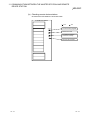
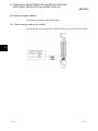
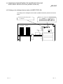
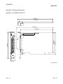
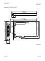
Appendix 19 External Dimensions ...........................................................................................................App-92
Appendix 19.1 Q80BD-J61BT11N ........................................................................................................App-92
Appendix 19.2 Q81BD-J61BT11 ..........................................................................................................App-93
R
INDEX
A - 18
Index- 1 to Index- 3
A - 18
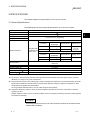
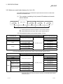
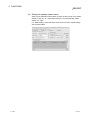
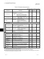
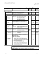
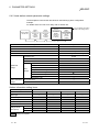
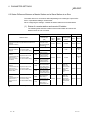
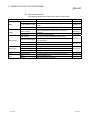
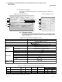
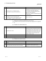
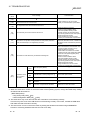
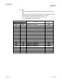
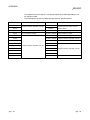
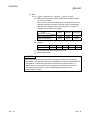
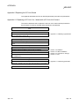
MANUALS
The following are the manuals related to this product.
Refer to the following tables when ordering required manuals.
Relevant Manuals
Manual Number
(Model Code)
Manual Name
MELSEC-Q CC-Link System Master/ Local Module User's Manual
This Manual explains system configuration, Performance specifications, functions, handling, wiring and
troubleshooting for Q series master/local module.
(Sold separately)
CC-Link System Master/ Local Module type AJ61BT11/A1SJ61BT11 User's Manual
This Manual explains system configuration, Performance specifications, functions, handling, wiring and
troubleshooting for AJ61BT11 and A1SJ61BT11.
(Sold separately)
CC-Link System Master/ Local Module type AJ61QBT11/A1SJ61QBT11 User's Manual
This Manual explains system configuration, Performance specifications, functions, handling, wiring and
troubleshooting for AJ61QBT11 and A1SJ61QBT11.
(Sold separately)
MELSEC-L CC-Link System Master/ Local Module User's Manual
This Manual explains system configuration, Performance specifications, functions, handling, wiring and
troubleshooting for L series master/local module.
(Sold separately)
MELSEC Data Link Library Reference Manual
This manual explains programming, function specifications, and sample programming for MELSEC data
link library.
(Sold separately)
SH-080394
(13JR64)
IB-66721
(13J872)
IB-66722
(13J873)
SH-080895
(13JZ41)
SH-081035ENG
(13JV25)
REMARK
MELSEC Data Link Library Reference Manual is stored on the CD-ROM of the
software package in a PDF file format.
Manuals in printed form are sold separately for a single purchase. Order a manual
by quoting the manual number (model code) listed in the above table.
A - 19
A - 19
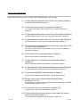
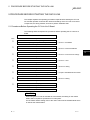
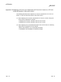
HOW TO USE THIS MANUAL
The following lists the key items that represent the main usage of the CC-Link Ver.2 board by the purpose.
Please use the following key items to refer to the appropriate section of this manual.
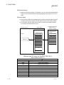
(1) To learn about the features of the CC-Link Ver.2 board (Chapter 1)
The features are described in Chapter 1.
(2) To learn about the system configuration (Chapter 2)
The system configuration using the CC-Link Ver.2 board is described in
Chapter 2.
(3) To learn about specifications of the CC-Link Ver.2 board (Chapter 3)
The specifications of the CC-Link Ver.2 board are described in Chapter 3.
(4) To learn about the functions of the CC-Link Ver.2 board (Chapter 4)
The functions of the CC-Link Ver.2 board are described in Chapter 4.
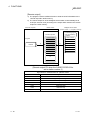
(5) To learn about the settings and procedures up to operation of CCLink Ver.2 board (Chapter 5)
The settings and procedures up to operation of the CC-Link Ver.2 board is
described in Chapter 5.
(6) To learn about how to set parameters (Chapter 6)
How to set parameters is described in Chapter 6.
(7) To learn about how to install and uninstall utility software
(Chapter 7)
How to install and uninstall utility software is described in Chapter 7.
(8) To learn about the utility software operating procedures (Chapter 8)
The utility software operating procedures are described in Chapter 8.
(9) To learn about MELSEC data link library (Chapter 9)
The overview of MELSEC data link library is described in Chapter 9.
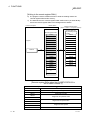
(10) To learn about how to communicate with each station
(Chapters 10 to 14)
Some examples of communication between the master board and each station
are described in Chapters 10 to 14.
(11) To learn about the error descriptions (Chapter 15)
The descriptions of errors are described in Chapter 15.
(12) To learn about the corrective actions to take when the system
does not operate (Chapter 16)
The troubleshooting procedures are described in Chapter 16.
A - 20
A - 20
GENERIC TERMS AND ABBREVIATIONS
This manual uses the following generic terms and abbreviations to describe the Model Q80BDJ61BT11N/Q81BD-J61BT11 CC-Link System Master/Local Interface Board, unless otherwise specified.
Generic term/abbreviation
Description of generic term/abbreviation
CC-Link Ver.1 board
Generic term for the Type A80BDE-J61BT11 CC-Link System Master/Local Interface Board and the Type
A80BDE-J61BT13 Control & Communication Link System Local Interface Board.
CC-Link Ver.2 board
Abbreviation for the Type Q80BD-J61BT11N/Q81BD-J61BT11 CC-Link System Master/Local Interface
Board.
Master board
Abbreviation for the CC-Link board when used as a master station.
Local board
Abbreviation for the CC-Link board when used as a local station.
QJ61BT11(N)
Generic term for QJ61BT11N CC-Link System Master/Local Module and QJ61BT11 CC-Link System
Master/Local Module.
SW1DNC-CCBD2-B
Master station
Product name of the software package for CC-Link Ver.2 board.
The station controlling the remote station, local station, and intelligent device station.
Standby master station
Backup station for data link control when the link to the master station is disconnected due to a
programmable controller CPU, Master board or power supply problem.
Local station
A station that has a CPU and can communication with the master station and local station.
Remote I/O station
A remote station that can only handle bit information.
, AJ65BTC )
(AJ65BTB -
Remote device station
Remote station that can use bit data and word data.
(Performs input and output with external devices, and analog data conversion.)
(AJ65BT-64AD, AJ65BT-64DAV, AJ65BT-64DAI)
Remote station
Generic term for the remote I/O station and remote device station.
Intelligent device station
A slave station such as the AJ65BT-R2 in the CC-Link system that can perform transient transmission.
Slave station
Generic term for remote I/O station, remote device station, local station, intelligent device station and
standby master station.
Ver.1 compatible slave station
Slave station compatible with the remote net ver.1 mode.
Ver.2 compatible slave station
Slave station compatible with the remote net ver.2 mode.
Master and local modules
Generic term for the AJ61QBT11, A1SJ61QBT11, AJ61BT11, A1SJ61BT11, QJ61BT11, LJ61BT11,
L26CPU-BT, L26CPU-PBT, and RJ61BT11.
Master module
Generic term for the Master and local modules when they are used as master stations.
Local module
Generic term for the Master and local modules when they are used as local stations.
Remote module
Generic term for AJ65BTB A852GOT, etc.
Intelligent module
Generic term for modules such as the AJ65BT-R2 that can perform transient transmission.
Cyclic transmission
Function that periodically updates the contents of the remote I/O and remote register.
Transient transmission
Function by which data communications are available between 1:1stations at any given timing by
specifying a target station.
Remote net mode
Mode that can communicate with all stations used for CC-Link (remote I/O station, remote device station,
local station, intelligent device station, and standby master station)
The remote net mode has three different modes: remote net ver.1 mode, remote net ver.2 mode, and
remote net additional mode.
Remote net ver.1 mode
Mode in which compatibility with the CC-Link Ver.1 board is achieved.
Select this mode when the number of cyclic points need not be increased or when the CC-Link Ver.2
board is used to replace the CC-Link Ver.1 board as a maintenance product.
, AJ65BTC -
, AJ65BT-64AD, AJ65BT-64DAV, AJ65BT-64DAI,
Remote net ver.2 mode
Select this mode when increasing the number of cyclic points and configuring a new system.
Remote net additional mode
Select this mode when adding a ver.2 compatible station to the existing system to increase the number of
cyclic points.
Board WDT
Abbreviation for the watchdog timer that monitors the operation of network board.
Driver WDT
Abbreviation for the watchdog timer that monitors the communication status between a network board
and a personal computer, or operating status of a personal computer.
A - 21
A - 21
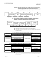
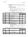
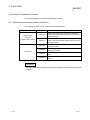
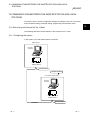
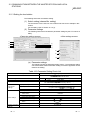
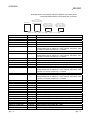
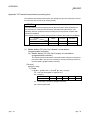
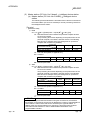
PACKING LIST
The following shows the product list of the CC-Link Ver.2 board.
Item name
Quantity
CC-Link system master/local interface board
1
Terminal resistor 110Ω, 1/2 W (brown-brown-brown)
2
Terminal resistor 130Ω, 1/2 W (brown-orange-brown)
2
Software package (CD-ROM)
*1
1
Before Using the Product
1
Software License Agreement
1
1: The manual is stored on the CD-ROM in a PDF file format.
A - 22
A - 22
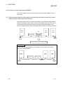
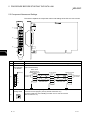
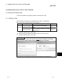
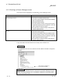
1 OVERVIEW
MELSEC
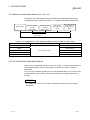
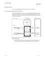
1 OVERVIEW
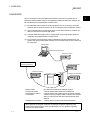
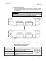
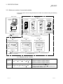
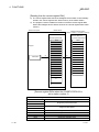
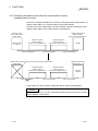
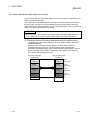
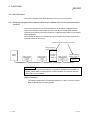
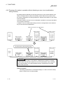
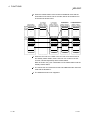
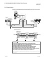
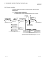
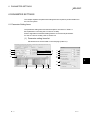
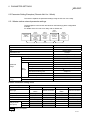
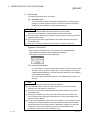
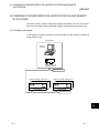
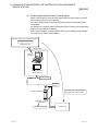
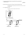
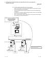
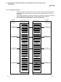
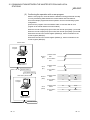
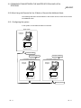
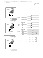
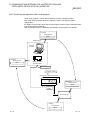
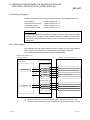
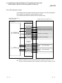
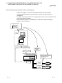
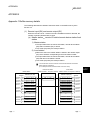
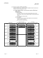
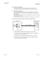
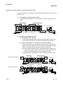
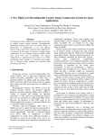
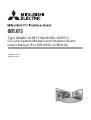
The CC-Link system connects distributed modules such as an I/O module and a
special functional module using CC-Link dedicated cables so that these modules can
be controlled by the programmable controller CPU.
(1) By distributing each module to facility equipment such as a conveyor line and a
machine device, the entire system can be connected in the most efficient manner.
(2) The on/off information of input/output and numeric data handled by modules can
easily be sent and received at high speed.
(3) A simple distributed system can be configured by connecting multiple personal
computers and programmable controller CPUs.
(4) By connecting various devices made by Mitsubishi's partner manufacturers, the
system that can provide flexible solutions to meet a wide range of user needs may
be configured.
Master station
Master/local interface board
Remote I/O station
Device manufactured by
a partner manufacturer
Remote device station
Remote I/O station
Local station
Intelligent device station
Programmable
controller CPU
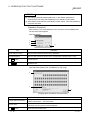
Master station
Remote I/O station
Remote device station
Local station
Intelligent device station
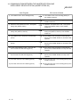
The station that controls the data link system.
A remote station that handles bit unit data only.
A remote station that handles bit unit and word unit data.
A station having a programmable controller CPU and the
ability to communicate with the master and other local
stations.
A station that can perform transient transmission.
When applying the program examples and sample programs explained in this
manual to the actual system, make sure that there is no any problem regarding
control on the target system.
1-1
1-1
1
1 OVERVIEW
MELSEC
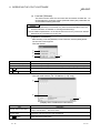
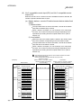
1.1 Features of the CC-Link Ver.2 Board
The features of the CC-Link Ver.2 board are as follows:
1
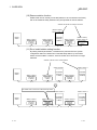
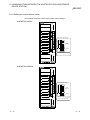
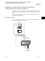
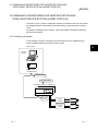
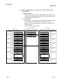
(1) Personal computers can be incorporated into the CC-Link system.
Installing a CC-Link Ver.2 board into a personal computer allows the PC to be
used as a master station, standby master station, or local station compatible with
CC-Link Ver.2.
By using the CC-Link Ver.2 board as a master station, Ver.2 compatible remote
I/O stations, remote device stations, intelligent device stations and local stations
can be controlled from the PC.
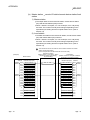
(2) Programs in the CC-Link Ver.1 board can also be used in the CCLink Ver.2 board.
Programs developed for the CC-Link Ver.1 board can be used for the CC-Link
Ver.2 board.
(3) Parameters set for the CC-Link Ver.1 board can also be used for
the CC-Link Ver.2 board.
Parameters set for the CC-Link Ver.1 board can be reused for the CC-Link Ver.2
board. (Refer to Appendix 7)
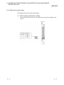
(4) PCI/PCI Express is applicable.
R
For Q80BD-J61BT11N, PCI is applicable.
For Q81BD-J61BT11, PCI Express is applicable.
R
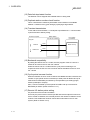
(5) Parameters can easily be set.
The parameters necessary for the operation of the CC-Link system can easily be
set with a CC-Link Ver.2 utility program; thus, programming is simplified.
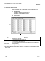
(6) Test and monitoring information related to the CC-Link system can
be displayed.
The test and monitoring states in the CC-Link system can be easily displayed on
a personal computer.
(7) Support for a multiple CPU system
By specifying the logical station number via the CC-Link Ver.2 utility, a multiple
CPU system can be accessed.
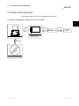
(8) It provides the functions that support user programming.
It is possible to perform the remote control of remote I/O stations, remote device
stations, intelligent device stations, and local stations, as well as reading and
writing of devices using the functions that support Microsoft Visual C++ and
Microsoft Visual Basic . Thus, user program can easily be created.
Example:
Control of the input signal X and output signal Y of a remote I/O station
Analogue voltage output control of a remote device station (analogue module)
Communication control of an intelligent device station (RS-232C module)
R
R
R
R
(9) It provides the drivers for various operating systems.
Various drivers are provided for easy system configuration according to the user
environment.
For details on the compatible operating system, refer to Section 2.3.
(10) Prevent separation of cyclic data by each station
In the CC-Link Ver.2 utility, cyclic data can be assured only by enabling the
parameter of block data assurance per station setting.
1-2
1-2
1 OVERVIEW
MELSEC
1.2 Features of the CC-Link System
This section explains the features of the CC-Link System.
(1) Remote I/O station communication
The on/off status of a switch or indicator lamp is communicated using the remote
input RX and remote output RY.
Personal computer
Master station
Remote I/O station
CC-Link Ver.2 board
Program
mdReceive
mdSend
Read
Remote input
RX
Link scan
Write
Remote output
RY
Link scan
Input
Output
(2) Remote device station communication
Handshaking signals with the remote device station (initial request, error
occurred flag, etc.) are communicated using the remote input RX and remote
output RY. The setting data to the remote device station are communicated using
the remote registers RWw and RWr.
Personal computer
CC-Link Ver.2 board
Program
mdReceive
mdSend
mdSend
mdReceive
1-3
Master station
Remote device station
Read
Remote input
RX
Link scan
Remote input
RX
Write
Remote output
RY
Link scan
Remote output
RY
Write
Remote
register
RWw
Read
Remote
register
RWr
Link scan
Link scan
Remote
register
RWw
Remote
register
RWr
1-3
1 OVERVIEW
MELSEC
(3) Local station communication
The communication between the master station and the local station uses two
types of transmission methods: cyclic transmission and transient transmission.
(a) Cyclic transmission
Data communication between stations can be performed in N : N mode
using bit data (remote input RX and remote output RY) and word data
(remote registers RWw and RWr).
Personal computer
Master station
Program
mdReceive
mdSend
mdSend
mdReceive
Read
CC-Link Ver.2 board
Local station
Remote input
RX
Remote output
RY
Remote output
RY
Write
Remote
register
RWw
Write
Read
Remote
register
RWr
Link scan
Link scan
Link scan
Link scan
Remote input
RX
Remote
register
RWr
Remote
register
RWw
PLC CPU
Automatic refresh
Y
Automatic refresh
X
Automatic refresh
D
Automatic refresh
D
(b) Transient transmission
Read and write operations can be performed for the local station buffer
memory and CPU device at an arbitrary timing (using the mdReceive and
mdSend functions, respectively).
Personal computer
Program
mdSend
mdReceive
mdSend
mdReceive
1-4
Master station
CC-Link Ver.2 board
Write
Read
Write
Read
Transient
transmission
Transient
transmission
Transient
transmission
Transient
transmission
Local station
PLC CPU
D
Buffer memory
1-4
1 OVERVIEW
MELSEC
(4) Intelligent device station communication
The communication between the master station and the intelligent device station
uses two types of transmission methods: cyclic transmission and transient
transmission.
(a) Cyclic transmission
Handshaking signals with the intelligent device station (positioning start,
positioning end, etc.) are communicated using the remote input RX and
remote output RY. Numeric data (positioning start number, present feed
value, etc.) is communicated using the remote registers RWw and RWr.
Master station
Personal computer
CC-Link Ver.2 board
Program
mdReceive
mdSend
mdSend
mdReceive
Intelligent device station
Read
Remote input
RX
Link scan
Remote input
RX
Write
Remote output
RY
Link scan
Remote output
RY
Write
Remote
register
RWw
Read
Remote
register
RWr
Link scan
Link scan
Remote
register
RWw
Remote
register
RWr
(b) Transient transmission
Read and write operations can be performed for the intelligent device station
buffer memory at an arbitrary timing (using the mdReceive and mdSend
functions, respectively).
Personal computer
Master station
CC-Link Ver.2 board
Program
mdSend
Intelligent device station
Write
Transient
transmission
Buffer memory
mdReceive
1-5
Read
Transient
transmission
1-5
1 OVERVIEW
MELSEC
(5) System down prevention (Slave station disconnect function)
Even if a module system fails because of power failure or power off, it will not
affect the communication with other normal modules since the system employs
the bus connection method.
Also, for a module using a 2-piece terminal block, the module can be replaced
during data link. (Replace the module after turning its power off. Also check that
the switch setting on the replaced module is same as the one set on the module
before replacement.) However, if the cable is disconnected, the data link to all
stations is disabled.
Station number 4
Master
station
Station number 1
Station number 3
Remote station
(occupying
2 stations)
Remote station
(occupying
1 station)
Local station
(occupying
1 station)
Station number 7
Station number 5
Local station
(occupying
4 stations)
Remote station
(occupying
2 stations)
Data link continues
Station number 4
Station number 7
Local station
(occupying
1 station)
Local station
(occupying
4 stations)
Faulty
station
Master
station
Station number 1
Station number 3
Remote station
(occupying
2 stations)
Remote station
(occupying
1 station)
Station number 5
Remote station
(occupying
2 stations)
(6) Auto return function
When a module that has been disconnected from the link due to power off
recovers and returns to the normal status, it will join the data link automatically.
(7) Input data status setting from a data-link faulty station
The data entered (received) from a data-link faulty station can be cleared, or the
status immediately before the error can be restored.
1-6
1-6
1 OVERVIEW
MELSEC
(8) Standby master function
This function enables the data link to continue working by switching to a standby
master station (backup station for the master station) if a malfunction occurs in
the master station.
POINT
The personal computer can be set as a standby master station only when the master
station is also a personal computer. If the master station is a programmable controller
CPU, the personal computer cannot be set as a standby master station.
Standby master station
Station number 1
Number of occupied stations: 1
Data link control
by the master station
Master station
Remote I/O station
Station number 2
Number of occupied stations: 1
Data link control
in progress
Cyclic communication
Master station is down
Master station
Remote I/O station
Station number 3
Number of occupied stations: 1
Cyclic communication
Cyclic communication
Standby master station
Station number: 1 0*1
Data link control by the standby master station
Remote I/O station
Station number 2
Number of occupied stations: 1
Cyclic communication
Remote I/O station
Station number 3
Number of occupied stations: 1
Cyclic communication
Standby
Control in
Progress
Cyclic communication
*1: When the master station is down and the data link control is switched to the standby master station, the station number of the
standby master station will be 0.
(9) Mode selection according to the system
The CC-Link system has 3 types of modes applicable to various systems. Select
one of the modes on <<Parameter settings>> in the CC-Link Ver.2 utility.
Refer to Appendix 12 for the mode selection.
Each of the modes is described below.
Mode
Remote net Ver.1 mode
Remote net Ver.2 mode
Remote net additional mode
1-7
Description
The compatibility mode with the CC-Link Ver.1 board.
Select this mode when the cyclic points increasing is not
required or when the CC-Link Ver.2 board is used as
substitute for the CC-Link Ver.1 board.
Select this mode when configuring a new system with the
cyclic points increasing.
Select this mode when adding a Ver.2 compatible slave
station to the existing system to increase the number of
cyclic points.
Connectable station
Remote I/O station
Remote device station
Intelligent device station
Local station
Standby master station
1-7
1 OVERVIEW
MELSEC
(10) Reserve station function
Stations that are not actually connected (stations to be connected in the future)
will not be treated as faulty stations if they are specified as reserve stations.
Stations that will be connected in the future
(Reserve station)
Station number 4
Master
station
Station number 1
Station number 3
Remote station
(occupying
2 stations)
Remote station
(occupying
1 station)
Local station
(occupying
4 stations)
Station number 8
(Reserve station)
Station number 10
Remote station
(occupying
2 stations)
Remote station
(occupying
1 station)
(11) Error invalid station setting function
By setting network parameters, a module that is powered off in the system
configuration will not be treated as a "data link faulty station" by the master
station and local station. However, exercise caution since errors are no longer
detected.
Stations to be set as error invalid stations
Station number 4
Master
station
Station number 1
Station number 3
Remote station
(occupying
2 stations)
Remote station
(occupying
1 station)
Local station
(occupying
1 station)
Station number 7
Station number 5
Remote station
(occupying
2 stations)
Local station
(occupying
4 stations)
This station does not become a data link faulty station.
Station number 4
Master
station
1-8
Station number 1
Station number 3
Remote station
(occupying
2 stations)
Remote station
(occupying
1 station)
Local station
(occupying
1 station)
Station number 7
Station number 5
Local station
(occupying
4 stations)
Remote station
(occupying
2 stations)
1-8
1 OVERVIEW
MELSEC
(12) Data link stop/restart function
The data link can be stopped and restarted while it is being used.
(13) Duplicate station number check function
This is a transmission method by which data communications are available
between 1:1stations at any given timing by specifying a target station.
(14) Transient transmission
In this method of transmission, a counterpart is specified and 1:1 communication
is performed at an arbitrary timing.
Personal computer
Master station
CC-Link Ver.2 board
Program
mdSend
mdReceive
Write
Local station
(1st station)
Buffer memory
Read
(15) Backward compatibility
By setting the Remote net ver.1 mode, the user program of the CC-Link Ver.1
board can be used on the CC-Link Ver.2 board.
Select the remote net ver.1 mode when the cyclic points increasing is not
required or when the CC-Link Ver.2 board is used as substitute for the CC-Link
Ver.1 board.
(16) Cyclic points increase function
When the Remote net ver.2 mode or Remote net additional mode is selected, the
number of cyclic points can be increased up to 8192 points for RX/RY and up to
2048 words for RWr/RWw per network by the expanded cyclic setting (single,
double, quadruple or octuple).
Also, it can be increased up to 224 points for RX/RY and up to 32 words for
RWr/RWw per station. (Refer to Section 4.4.7)
(17) Remote I/O station points setting
I/O points are set for remote I/O stations.
Since only the points used in remote input RX and remote output RY need to be
set for remote I/O stations, the reserved points for the remote I/O stations can be
reduced. This enables the minimum remote device allocation in the CC-Link
system. (Refer to Section 4.4.6)
1-9
1-9
1 OVERVIEW
MELSEC
MEMO
1 - 10
1 - 10
2 SYSTEM CONFIGURATION
MELSEC
2 SYSTEM CONFIGURATION
This chapter explains the system configuration of the CC-Link.
2.1 System Configuration Using CC-Link Ver.2 Board
2
Installed
Connection
Connection
CC-Link
dedicated cable
Personal computer
CC-Link
system
Q80BD-J61BT11N
Q81BD-J61BT11
Installed
SW0DNC-CCBD2-B
2-1
2-1
2 SYSTEM CONFIGURATION
MELSEC
2.2 Notes on the System Configuration
(1) Combinations of master and standby master stations
The following table shows the combination availability for the master station and
standby master station in the system configuration.
2
Standby master station
Q80BD-J61BT11N
Q81BD-J61BT11
Ver.2
Mode
Master station
Additional
mode
A80BD-J61BT11
A80BD-J61BT13
Ver.1
Mode
Ver.1 mode
RJ61BT11*1
LJ61BT11
L26CPU-BT
L26CPU-PBT
QJ61BT11N
Ver.2 Additional Ver.1
Mode
mode
Mode
QJ61BT11
AJ61BT11
A1SJ61BT11
AJ61QBT11
A1SJ61QBT11
Ver.1
Mode
Ver.2 Mode
Q80BD-J61BT11N
Q81BD-J61BT11
Additional mode
Ver.1 Mode
A80BD-J61BT11
Ver.1 Mode
RJ61BT11*1
LJ61BT11
L26CPU-BT
L26CPU-PBT
QJ61BT11N
Ver.2 Mode
QJ61BT11
Additional mode
Ver.1 Mode
Ver.1 Mode
: Available,
: Not available
*1: The additional mode is not supported.
(2) Incorporating the CC-Link Ver.1 board into the CC-Link Ver.2
network system
Use any of the following software versions to utilize the CC-Link Ver.1 board at a
local station when the master station is in the remote net ver.2 mode or remote
net additional mode.
A80BDE-J61BT11: Version "R" or later
A80BDE-J61BT13: Version "Y" or later
Refer to Appendix 10 for how to check the software version.
(3) System design to prevent erroneous inputs from the remote I/O
modules
(a) When powering on and off
Start the data link after turning on the power to the remote I/O modules.
Turn off the power to the remote I/O modules after stopping the data link.
Data link start
CC-Link Ver.2 board
(data link status)
Remote I/O module
(power status)
2-2
Data link stop
Executing
Stopped
ON
OFF
2-2
2 SYSTEM CONFIGURATION
MELSEC
(b) During momentary power failure of the remote I/O modules
When a momentary power failure occurs in the power being supplied to the
remote I/O modules (24 V DC), an erroneous input may occur.
[Cause for erroneous inputs due to a momentary power failure]
The remote I/O module hardware uses the power by internally converting
the module power (24 V DC) to 5 V DC.
When a momentary power failure occurs in a remote I/O module, the
following situation occurs:
(Time for the 5 V DC power in the remote I/O module to turn off)
> (Response time for input module on off)
Thus, an erroneous input occurs when a refresh is performed within the
time indicated by 1) in the figure below.
1)
Remote I/O module
(module power supply and input
external supply power)
Remote I/O module
(internal 5 V DC)
Input (Xn)
When the input external power supply turns off, the input (Xn) turns off
after the response time for the input module changes from on to off.
REMARK
When supplying power from a single power source to multiple remote I/O modules,
select the proper type of cable and perform wiring by considering the voltage drop.
Connections can be established if the receiving port voltage at the remote I/O
module is within the specified range of the remote I/O module to be used.
Stabilized
power supply
Remote module
Remote module
(4) Access to slave station No.64
When the CC-Link Ver.2 board is used, transient transmission to slave station
No.64 is not allowed.
REMARK
(1) Access to slave station No.64 is not possible even from GX Developer, GX
Works2 or GOT on any other station.
(2) Cyclic transmission can be normally performed with slave station No.64.
2-3
2-3
2 SYSTEM CONFIGURATION
MELSEC
2.3 Operating Environment
The following table shows the operating environment for CC-Link Ver.2 board.
For details on the personal computer and operating system, refer to the instructions on
the following pages.
Item
Description
Windows supported personal computer
R
CPU
Personal
computer
Required
memory
System requirements of the operating system must be met.
PCI bus
specifications
For Q80BD-J61BT11N
PCI Express
bus
specifications
For Q81BD-J61BT11
R
Compliant with PCI standard Rev.2.2 (5V DC, 32-bit bus, Basic clock : 33MHz)
Compliant with PCI Express
100MHz)
R
standard Rev.1.0a (3.3 V DC, Link width : 1lane, Basic clock :
Microsoft Windows NT Workstation Operating System Version 4.0, Service Pack3 or
3
higher
R
3
Microsoft Windows 2000 Professional Operating System
R
R
R
Operating system
(English version)
1
2
Microsoft
Microsoft
Microsoft
Microsoft
Microsoft
Microsoft
Microsoft
Microsoft
Microsoft
Microsoft
Microsoft
Microsoft
Microsoft
Microsoft
Microsoft
R
Microsoft
Microsoft
Microsoft
Microsoft
Microsoft
Microsoft
R
Microsoft
Microsoft
Microsoft
Microsoft
Microsoft
R
R
R
R
R
R
R
R
R
R
R
R
R
R
R
R
R
R
R
R
R
R
R
R
5
Windows XP Professional Operating System
5
Windows XP Home Edition Operating System
5
Windows Server 2003 R2, Standard Edition Operating System
5
Windows Server 2003 R2, Enterprise Edition Operating System
Windows Server 2003 R2, Standard x64 Edition Operating System
Windows Server 2003 R2, Enterprise x64 Edition Operating System
5
Windows Vista Home Basic Operating System
5
Windows Vista Home Premium Operating System
5
Windows Vista Business Operating System
5
Windows Vista Ultimate Operating System
5
Windows Vista Enterprise Operating System
5
Windows Server 2008 Standard Operating System
5
Windows Server 2008 Enterprise Operating System
5
Windows Server 2008 Standard x64 Edition Operating System
5
Windows Server 2008 Enterprise x64 Edition Operating System
R
R
R
R
R
R
5
5
R
R
R
R
R
R
R
R
R
Windows Server 2008 R2, Standard Operating System
Windows Server 2008 R2, Enterprise Operating System
Windows 7 Home Premium (32-bit version / 64-bit version) Operating System
Windows 7 Professional (32-bit version / 64-bit version) Operating System
Windows 7 Ultimate (32-bit version / 64-bit version) Operating System
Windows 7 Enterprise (32-bit version / 64-bit version) Operating System
R
R
R
R
R
R
Windows Server 2012 , Standard Operating System
Windows Server 2012 R2 , Standard Operating System
Windows 8 (32-bit version / 64-bit version) Operating System
Windows 8 Pro (32-bit version / 64-bit version) Operating System
Windows 8 Enterprise (32-bit version / 64-bit version) Operating System
R
R
R
R
R
Microsoft Windows 8.1 (32-bit version / 64-bit version) Operating System
Microsoft Windows 8.1 Pro (32-bit version / 64-bit version) Operating System
Microsoft Windows 8.1 Enterprise (32-bit version / 64-bit version) Operating System
R
R
R
R
R
R
Display
Resolution: 800 600 dot or higher (Recommended: 1024 768 dot)
Available hard disk space
1GB or more
Disk drive
CD-ROM disk drive
2-4
2-4
2 SYSTEM CONFIGURATION
MELSEC
Item
Description
Microsoft
Microsoft
Microsoft
Microsoft
Microsoft
Microsoft
Microsoft
Programming language
(English version)
2 *4
R
R
R
R
R
R
R
Visual Basic
Visual Basic
Visual Basic
Visual Studio
Visual Studio
Visual Studio
Visual Studio
R
R
R
R
R
R
R
5.0
6.0
.NET 2003
2005 Visual Basic
2008 Visual Basic
2010 Visual Basic
2012 Visual Basic
Microsoft Visual Studio 2013 Visual Basic
R
R
R
R
R
R
R
Microsoft Visual C++ 5.0
R
Microsoft
Microsoft
Microsoft
Microsoft
R
R
R
R
R
Visual C++ 6.0
Visual C++ .NET 2003
Visual Studio 2005 Visual C++
Visual Studio 2008 Visual C++
R
R
R
R
R
R
Microsoft Visual Studio 2010 Visual C++
R
Microsoft Visual Studio 2012 Visual C++
R
Microsoft Visual Studio 2013 Visual C++
R
R
R
R
R
R
R
1: Windows XP (64-bit version) and Windows Vista (64-bit version) are not supported.
2: For a combination of the operating system and the programming language, refer to the Microsoft
Knowledge Base.
3: Not supported by SW1DNC-CCBD2-B Version 1.13P or later. When using one of these operating system,
use SW1DNC-CCBD2-B Version 1.12N or earlier. SW1DNC-CCBD2-B Version 1.12N and its supported
manual are stored on the CD-ROM of this product. (Refer to Appendix 14)
4: When creating 64-bit version Visual Basic application to be used for the MELSEC data link library, use
Visual Studio 2010 or later because .NET Framework 4.0 or .NET Framework compatible with .NET
Framework 4.0 is required.
5: Not supported by SW1DNC-CCBD2-B Version 1.17T or later. When using one of these operating system,
use SW1DNC-CCBD2-B Version 1.16S or earlier. SW1DNC-CCBD2-B Version 1.16S and its supported
manual are stored on the CD-ROM of this product. (Refer to Appendix 14)
R
(1) Instructions for personal computer
(a) PCI standard
When a personal computer which is not compliant with the PCI or PCI
Express standard is used, troubles caused by failures such as a contact
failure or operation error may occur.
For details on the number of boards that can be installed, installation slot
and occupied slots, refer to Section 3.2.
R
(b) The functions being added
Operating environment
Multiprocessor
2-5
Supported version
Version 1.06G or later
2-5
2 SYSTEM CONFIGURATION
MELSEC
(2) Instructions for operating system
(a) Supported version of SW1DNC-CCBD2-B
Supported version
Operating system
Windows NT
Windows 2000
Windows XP
Windows Vista
Windows Server 2003 R2 (32-bit version)
Windows Server 2003 R2 (64-bit version)
Windows Server 2008 (32-bit version)
Windows Server 2008 (64-bit version)
Windows 7 (32-bit version)
Windows Server 2008 R2,
Windows 7 (64-bit version)
Windows Server 2012,
Windows 8
Windows Server 2012 R2,
Windows 8.1
R
R
R
R
R
R
R
R
R
Q80BD-J61BT11N
Q81BD-J61BT11
Version 1.12N or earlier
Not supported
Version 1.12N or earlier
Version 1.06G to 1.12N
Version 1.16S or earlier
Version 1.06G to 1.16S
Version 1.04E to 1.16S
Version 1.06G to 1.16S
Version 1.11M to 1.16S
Version 1.08J to 1.16S
Version 1.11M to 1.16S
1
Version 1.08J or later
R
R
Version 1.11M or later
1
R
R
Version 1.13P or later
R
R
Version 1.15R or later
1: When using SW1DNC-CCBD2-B Version 1.17 T or later, apply Service Pack1 and
Windows security update program KB3033929. Use SW1DNC-CCBD2-B Version
1.16S or earlier, if Service Pack1 and KB3033929 cannot be applied.
SW1DNC-CCBD2-B Version 1.16S and its supported manual are stored on the CDROM of this product. (Refer to Appendix 14)
R
(b) User authority
Log on as a user having administrator authority.
Installation, uninstallation and usage of utilities are available only by the
administrator's authority.
(c) .NET Framework 3.5
When using one of the following operating system, .NET Framework 3.5 is
required.
Windows Server 2012
Windows Server 2012 R2
Windows 8
Windows 8.1
Enable the .NET Framework 3.5 (including .NET 2.0 or 3.0) in "Turn
Windows features on or off" on the control panel.
R
R
R
R
(d) Update Windows
R
8.1
Updating Windows 8.1 is not supported.
When updating Windows 8.1, install SW1DNC-CCBD2-B with the
software Version 1.15R or later after uninstalling the software package and
updating Windows 8.1.
R
R
R
2-6
2-6
2 SYSTEM CONFIGURATION
MELSEC
(e) The functions cannot be used
The following functions of operating system cannot be used. If an attempt is
made to use any of the following functions, this product may not operate
normally.
• Activating the application with Windows compatible mode.
• Simplified user switch-over
• Remote desktop
• Large font size (Advanced setting of screen property)
• DPI setting other than 100%
(set the size of text and illustration other than [smaller-100%])
• Power save mode (Standby, Hibernate, Sleep)
• Fast startup
• The language switching function set by Regional and Language Options
• Windows XP Mode
• Windows Touch or Touch
• Modern UI
• Client Hyper-V
• Server Core Installation
• Upgrade the operating system
R
REMARK
• When exiting the operating system, always shut down the computer.
• The behavior of the board and the personal computer when the personal computer
enters the power save mode differs according to the operating system.
For details of error codes and messages when the power save mode set by a user
or a program is entered, refer to Appendix 16.
• Upgrading the operating system is not supported. Install SW1DNC-CCBD2-B by
following the procedure shown below.
1) Uninstall SW1DNC-CCBD2-B.
2) Upgrade the operating system.
3) Install SW1DNC-CCBD2-B with the software version supporting the upgraded
operating system.
2-7
2-7
2 SYSTEM CONFIGURATION
MELSEC
(3) Instructions for user program
(a) Supported version of SW1DNC-CCBD2-B
User program
Supported version
32-bit version user program
1
All versions
64-bit version user program
2
Version 1.11M or later
1: Programs can be created and executed on the 64-bit version operating system.
2: Programs can be created on the 32-bit version operating system, however, the
following dialog box appears and cannot be executed.
<When using Windows XP (32-bit version)>
R
R
<When using Windows 7 (32-bit version)>
(b) User programs created in the Japanese environment work
only in the Japanese environment.
(c) User programs created in the English environment work only in
the English environment.
2-8
2-8
3 SPECIFICATIONS
MELSEC
3 SPECIFICATIONS
This chapter explains the specifications of CC-Link Ver.2 board.
3.1 General Specifications
The following table shows the general specifications of CC-Link Ver.2 board.
Item
Specification
Operating ambient temperature
0 to 55
Storage ambient temperature
3
-25 to 75
Operating ambient humidity
5 to 95 % RH, non-condensing
Storage ambient humidity
Under Intermittent vibration
Compliant with
JIS B 3502 and
IEC 61131-2
Vibration resistance
Frequency
Constant
acceleration
Half amplitude
Sweep count
5 to 8.4 Hz
—
3.5 mm
8.4 to 150 Hz
9.8 m/s
10 times each in
X, Y, Z
directions
2
—
Under Continuous vibration
Frequency
5 to 8.4 Hz
8.4 to 150 Hz
Constant
acceleration
Half amplitude
—
2
4.9 m/s
1.75 mm
—
Sweep count
—
2
Compliant with JIS B 3502 and IEC 61131-2 (147 m/s , 3 times each in X, Y, Z
directions)
Shock resistance
Operating atmosphere
Operating altitude
1
Installation location
Overvoltage category
Pollution degree
No corrosive gases
0 to 2000 m
Inside a control panel
2
II or less
3
2 or less
1: Do not use or store the board under the environment where the atmospheric pressure is higher than the one at the
altitude of 0 m. Doing so may cause a malfunction.
2: This indicates the section of the power supply to which the equipment is assumed to be connected between the public
electrical power distribution network and the machinery within premises. Category II applies to equipment for which
electrical power is supplied from fixed facilities.
The surge voltage withstand level for up to the rated voltage of 300V is 2500V.
3: This index indicates the degree to which conductive material is generated in terms of the environment in which the
equipment is used.
Pollution degree 2 is when only non-conductive pollution occurs. A temporary conductivity caused by condensing must
be expected occasionally.
REMARK
General specifications both CC-Link Ver.2 board and a personal computer must be
satisfied after installation.
3-1
3-1
3 SPECIFICATIONS
MELSEC
3.2 Performance Specifications
Table 3.1 shows the performance specifications of the CC-Link Ver.2.
Table 3.1 Performance specifications
Item
Transmission rate
3
Overall cable distance
(maximum transmission distance)
Maximum number of connected stations
(master station)
Occupied station count
(when mounted to local station)
Maximum number of link points per
system 1
Remote station/local station/intelligent
device station/standby master station
Number of link points per link 1
Specification
Q80BD-J61BT11N
Q81BD-J61BT11
Can select from 156 kbps / 625 kbps / 2.5 Mbps / 5 Mbps / 10 Mbps
Varies according to the transmission rate (Refer to Section 3.2.2, 3.2.3)
64 (Refer to Section 3.2.1 for the conditions for the number of connected stations)
In remote net ver.1 mode:
1 or 4 station(s) (Can be changed on <<Parameter settings>> in the
CC-Link Ver.2 utility.)
In remote net ver.2 mode, remote net additional mode:
1 to 4 station(s) (Can be changed on <<Parameter settings>> in the
CC-Link Ver.2 utility.)
Remote I/O (RX, RY): 2048 points
Remote register (RWw): 256 points (master station
remote station/local station/intelligent
device station/standby master station)
Remote register (RWr): 256 points (remote station/local station/ intelligent device
master station)
station/standby master station
Remote I/O (RX, RY): 32 points (local station is 30 points)
Remote register (RWw): 4 points (master station
remote station/local station/intelligent
device station/standby master station)
Remote register (RWr): 4 points (remote station/local station/intelligent device station/standby
master station)
master station
Communication method
Broadcast polling method
Synchronous method
Frame synchronous method
Encoding method
NRZI method
Transmission path
Bus format (conforms to EIA RS-485)
Transmission format
Conforms to HDLC
Error control system
CRC (X16 + X12 + X5 + 1)
Connection cable
RAS function
CC-Link dedicated cable/ CC-Link dedicated high performance cable/
Ver.1.10-compatible CC-Link dedicated cable 2
• Auto return function
• Slave station disconnect function
• Error detection by the link special relay/register
Number of boards that may be used in
one system
Loading slot
Bus performance
Maximum 4
Occupied slot
5 V DC internal current consumption
3.3 V DC Internal current consumption
Weight
3-2
PC PCI Express
X1, X2, X4, X8, X16 slot (half size)
R
PC PCI bus slot (half size)
PCI bus
Bus width: 32 bits
Bus clock frequency: 0 to 33MHz
5V DC 5%
PCI standard Rev.2.2
3
PCI Express
Link width: 1 lane
Transmission speed: 2.5Gb/s
3.3V DC 9%
PCI Express standard Rev.1.0a
R
R
1 slot
0.56A
—
—
1.06A
0.11kg
0.11kg
3-2
3 SPECIFICATIONS
MELSEC
1: The link points shown above apply to the use in the remote net ver.1 mode.
Refer to Table 3.2 for those in the remote net ver.2 mode, remote additional mode.
2: Ver.1.10-compatible CC-Link dedicated cables, CC-Link dedicated cables (Ver.1.00) and CC-Link dedicated highperformance cables cannot be used together. If used together, correct data transmission will not be guaranteed.
Also attach the terminating resister which matches the kind of the cable. (Refer to Section 5.4.1)
3: Using the CC-Link Ver.2 board and the CC-Link Ver.1 board in the same computer is not allowed.
Table 3.2 Number of link points for remote net ver.2 mode/remote net additional mode
Item
Specifications
Maximum No. of link points per system
Expanded cyclic setting
No. of link points
per station
Single
Double
Quadruple
Octuple
32 points
(30 points for
local station)
32 points
(30 points for
local station)
64 points
(62 points for
local station)
128 points
(126 points for
local station)
Remote register (RWw)
4 points
8 points
16 points
32 points
Remote register (RWr)
Remote I/O (RX, RY)
Occupies
1 station
Occupies
2 stations
Number of link
points per
occupied station
count
Occupies
3 stations
Occupies
4 stations
3-3
Remote I/O (RX, RY) : 8192 points
Remote register (RWw) : 2048 points (master station remote device
station/local station/intelligent device
station/standby master station)
Remote register (RWr) : 2048 points (remote device station/local
station/intelligent device station/standby
master station master station)
4 points
8 points
16 points
32 points
Remote I/O
(RX, RY)
32 points
32 points
64 points
128 points
Remote register
(RWw)
4 points
8 points
16 points
32 points
Remote register
(RWr)
4 points
8 points
16 points
32 points
Remote I/O
(RX, RY)
64 points
96 points
192 points
384 points
Remote register
(RWw)
8 points
16 points
32 points
64 points
Remote register
(RWr)
8 points
16 points
32 points
64 points
Remote I/O
(RX, RY)
96 points
160 points
320 points
640 points
Remote register
(RWw)
12 points
24 points
48 points
96 points
Remote register
(RWr)
12 points
24 points
48 points
96 points
Remote I/O
(RX, RY)
128 points
224 points
448 points
896 points
Remote register
(RWw)
16 points
32 points
64 points
128 points
Remote register
(RWr)
16 points
32 points
64 points
128 points
3-3
3 SPECIFICATIONS
MELSEC
3.2.1 Maximum number of connected modules
A CC-Link system can be configured with the number of modules meeting the following
conditions.
Master station
Maximum 26
Personal
computer
Local station
Local station
Local station
Local station
Personal
computer
+
+
RJ61BT11
LJ61BT11
L26CPU-BT
L26CPU-PBT
QJ61BT11(N)
Q80BD-J61BT11N
Q81BD-J61BT11
A1SJ61QBT11
AJ61QBT11
Terminal resistor (required)
A1SJ61BT11
AJ61BT11
Q80BD-J61BT11N
Q81BD-J61BT11
A80BDE-J61BT11
A80BDE-J61BT13
CC-Link dedicated cable
Maximum 26
Maximum 42
Maximum 64
Intelligent device station
Remote device station
Remote I/O station
RS-232 interface module
AJ65BT-R2
Analog/digital converter
AJ65BT-64AD
Remote I/O module
AJ65BTB1-16D
AJ65BTC1-32D
CC-Link dedicated cable
Terminal resistor (required)
Total 64
(1) Remote net ver.1 mode
Condition 1 {(1
Condition 2 {(16
3-4
a) + (2
A) + (54
b) + (3
c) + (4
B) + (88
d)} 64
C)} 2304
a: Number of modules occupying 1 station
b: Number of modules occupying 2 stations
c: Number of modules occupying 3 stations
d: Number of modules occupying 4 stations
A: Number of remote I/O stations 64
B: Number of remote device stations 42
C: Number of local stations, standby master stations and
intelligent device stations 26
3-4
3 SPECIFICATIONS
MELSEC
(2) Remote net ver.2 mode, remote net additional mode
{(a + a2 + a4 + a8)
+ (b + b2 + b4 + b8)
Condition 1
+ (c + c2 + c4 + c8)
+ (d + d2 + d4 + d8)
2
3
4} 64
[{(a 32) + (a2 32) + (a4
+ {(b 64) + (b2 96) + (b4
Condition 2
+ {(c 96) + (c2 160) + (c4
+ {(d 128) + (d2 224) + (d4
a: The total number of ver.1 compatible slave
stations that occupy 1 station, and ver.2
compatible slave stations that occupy 1 station
which are set to "Single".
b: The total number of ver.1 compatible slave
stations that occupy 2 stations, and ver.2
64) + (a8 128)}
compatible slave stations that occupy 2 stations
192) + (b8 384)}
which are set to "Single".
320) + (c8 640)}
c: The total number of ver.1 compatible slave
448) + (d8 896)}] 8192
stations that occupy 3 stations, and ver.2
compatible slave stations that occupy 3 stations
which are set to "Single".
d: The total number of ver.1 compatible slave
stations that occupy 4 stations, and ver.2
compatible slave stations that occupy 4 stations
which are set to "Single".
a2: The number of ver.2 compatible stations that
occupy 1 station which are set to "Double".
b2: The number of ver.2 compatible stations that
occupy 2 stations which are set to "Double".
c2: The number of ver.2 compatible stations that
occupy 3 stations which are set to "Double".
d2: The number of ver.2 compatible stations that
occupy 4 stations which are set to "Double".
[{(a 4) + (a2 8) + (a4 16) + (a8 32)}
+ {(b 8) + (b2 16) + (b4 + 32) + (b8 64)}
a4: The number of ver.2 compatible stations that
Condition 3
+ {(c 12) + (c2 24) + (c4 48) + (c8 96)}
occupy 1 station which are set to “Quadruple”.
+ {(d 16) + (d2 32) + (d4 64) + (d8 128)}] 2048 b4: The number of ver.2 compatible stations that
occupy 2 stations which are set to "Quadruple".
c4: The number of ver.2 compatible stations that
occupy 3 stations which are set to "Quadruple".
d4: The number of ver.2 compatible stations that
occupy 4 stations which are set to "Quadruple".
a8: The number of ver.2 compatible stations that
occupy 1 station which are set to "Octuple".
b8: The number of ver.2 compatible stations that
occupy 2 stations which are set to "Octuple".
c8: The number of ver.2 compatible stations that
occupy 3 stations which are set to "Octuple".
d8: The number of ver.2 compatible stations that
occupy 4 stations which are set to "Octuple".
Condition 4 {(16
3-5
A) + (54
B) + (88
C) } 2304
A: Number of remote I/O stations 64
B: Number of remote device stations 42
C: Number of local stations, standby master
stations and intelligent device stations 26
3-5
3 SPECIFICATIONS
MELSEC
3.2.2 Maximum overall cable distance (for Ver.1.00)
The relationship between the transmission speed and the maximum overall cable
distance is described below:
(1) For a system consisting of only remote I/O stations and remote
device stations
Remote I/O station
or remote
device station
Remote I/O station
or remote
device station
Master station
2
2
Remote I/O station
or remote
device station
Remote I/O station
or remote
device station
1
1
Maximum overall cable distance
1: Cable length between remote I/O stations or remote device stations.
2: Cable length between the master station and the adjacent stations.
CC-Link dedicated cable (uses terminal resistor 110 )
Transmission rate
156 kbps
625 kbps
2.5 Mbps
5 Mbps
10 Mbps
Station-to-station cable length
1
2
1200 m (3937.2 ft.)
600 m (1968.6 ft.)
200 m (656.2 ft.)
30 cm (11.81 in.) or more
30 cm (11.81 in.) to
59 cm (23.23 in.) 3
60 cm (23.62 in.) or more
30 cm (11.81 in.) to
59 cm (23.23 in.) 3
60 cm (23.62 in.) to
99 cm (38.98 in.) 3
1 m (3.28 ft.) or more
Maximum overall cable distance
110 m (360.9 ft.)
1 m (3.28 ft.) or more
150 m (492.15 ft.)
50 m (164.1 ft.)
80 m (262.5 ft.)
100 m (328.1 ft.)
CC-Link dedicated high performance cable (uses terminal resistor 130 )
Transmission rate
156 kbps
625 kbps
2.5 Mbps
5 Mbps
Number of connected
stations: 1 to 32
Number of connected
stations: 33 to 48
10 Mbps
Number of connected
stations: 49 to 64
Station-to-station cable length
1
2
Maximum overall cable distance
1200 m (3937.2 ft.)
900 m (2952.9 ft.)
400 m (1312.4 ft.)
160 m (524.96 ft.)
30 cm (11.81 in.) or more
100 m (328.1 ft.)
30 cm (11.81 in.) to
39 cm (15.35 in.) 3
40 cm (15.75 in.) or more
30 cm (11.81 in.) to
39 cm (15.35 in.) 3
40 cm (15.75 in.) to
69 cm (27.17 in.) 3
70 cm (27.56 in.) or more
1 m (3.28 ft.) or more
80 m (262.5 ft.)
100 m (328.1 ft.)
20 m (65.52 ft.)
30 m (98.43 ft.)
100 m (328.1 ft.)
3: The cable length between remote I/O stations or remote device stations is within this
range and if even one location is wired, the maximum overall cable distance will be
as indicated above.
3-6
3-6
3 SPECIFICATIONS
MELSEC
(Example) When the transmission rate is 10 Mbps, and 43 remote I/O stations
and remote device stations are connected using the CC-Link
dedicated high performance cable, because the cable connecting the
second and third stations is "35 cm (13.78 in.)", the maximum overall
cable distance will be "80 cm (31.5 in.)".
Master station
First
Second
Third
4th
43th
Remote I/O station
Remote device
station
Remote I/O station
Remote I/O station
Remote device
station
1 m (3.28 ft.)
50 cm (19.69 in.)
35 cm (13.78 in.)
50 cm (19.69 in.)
(2) For a system consisting of remote I/O stations, remote device
stations, local stations and intelligent device stations
2
Local station
or Intelligent
device station
Remote I/O station
or remote
device station
Remote I/O station
or remote
device station
Master station
1
2
Local station
or Intelligent
device station
2
Maximum overall cable distance
1: Cable length between remote I/O stations or remote device stations
2: Cable length between the master station or the local or intelligent device station and
the adjacent stations
CC-Link dedicated cable (uses terminal resistor 110 )
Transmission rate
156 kbps
625 kbps
2.5 Mbps
5 Mbps
Station-to-station cable length
1
2
30 cm (11.81 in.) or more
30 cm (11.81 in.) to 59 cm (23.23 in.)
60 cm (23.62 in.) or more
30 cm (11.81 in.) to 59 cm (23.23 in.)
60 cm (23.62 in.) to 99 cm (38.98 in.)
1 m (3.28 ft.) or more
10 Mbps
3
2 m (6.56 ft.) or more
3
3
Maximum overall cable distance
1200 m (3937.2 ft.)
600 m (1968.6 ft.)
200 m (656.2 ft.)
110 m (360.9 ft.)
150 m (492.15 ft.)
50 m (164.1 ft.)
80 m (262.5 ft.)
100 m (328.1 ft.)
CC-Link dedicated high performance cable (uses terminal resistor 130 )
Transmission rate
156 kbps
625 kbps
2.5 Mbps
5 Mbps
10 Mbps
Station-to-station cable length
1
2
30 cm (11.81 in.) or more
30 cm (11.81 in.) to 59 cm (23.23 in.)
60 cm (23.62 in.) or more
70 cm (27.56 in.) to 99 cm (38.98 in.)
1 m (3.28 ft.) or more
3
3
2 m (6.56 ft.) or more
Maximum overall cable distance
1200 m (3937.2 ft.)
600 m (1968.6 ft.)
200 m (656.2 ft.)
110 m (360.9 ft.)
150 m (492.15 ft.)
50 m (164.1 ft.)
80 m (262.5 ft.)
3: The cable length between remote I/O stations or remote device stations is within this
range and if even one location is wired, the maximum overall cable distance will be
as indicated above.
3-7
3-7
3 SPECIFICATIONS
MELSEC
3.2.3 Maximum overall cable distance (for Ver.1.10)
The relation of the transmission speed and maximum overall cable distance when
configuring the entire system with Version 1.10 modules and cable is shown below.
Remote I/O station
or remote
device station
Master station
Remote I/O station
or remote
device station
Local station or
intelligent device
station
Local station or
intelligent device
station
Station to station
cable length
Maximum overall cable distance
Version 1.10 compatible CC-Link dedicated cable (terminal resistor of 110 used)
Transmission speed
Station to station cable length
156kbps
Maximum overall cable distance
1200m (3937.2 ft)
625kbps
900m (2952.9 ft)
2.5Mbps
20 cm (7.88 in) or longer
400m (1312.4 ft)
5Mbps
160m (524.96ft)
10Mbps
100m (328.1 ft)
3.3 CC-Link Dedicated Cable Specifications
Use the CC-Link dedicated cable for the CC-Link system. If a cable other than the CCLink dedicated cable is used, the performance of the CC-Link system cannot be
guaranteed.
If you have any questions regarding the CC-Link dedicated cable, or if you wish to see
its specifications, refer to the CC-Link Partner Association homepage http://www.cclink.org/.
REMARK
For details, refer to the CC-Link cable wiring manual issued by CC-Link Partner
Association.
3-8
3-8
3 SPECIFICATIONS
MELSEC
3.4 Buffer Memory List
"Buffer memory" is a memory area used for data transfer between the user program
and the CC-Link Ver.2 board.
The data of the buffer memory return to their defaults when the CC-Link Ver.2 board is
reset by powering OFF the PC or resetting the CC-Link Ver.2 Utility.
The buffer memory list is shown.
Address
Hexadecimal Decimal
0000H
to
00DFH
00E0H
to
0015FH
0160H
to
01DFH
0
to
223
224
to
351
352
to
479
Item
Use prohibited
Description
1
Remote input (RX)
—
2
For the master station: Stores the input status
from the remote/local/
intelligent device/standby
master stations.
For the local station:
Availability
Read/write
Master Local Reference
possibility
station station
—
—
—
—
Read only
Stores the input status
from the master station.
—
For the master station: Stores the output status to
the remote/local/intelligent
Write only
device/standby master
stations.
For the local station:
Remote output (RY) 2
—
Stores the output status to
the master station.
Read/write
Also, stores the receive
data from the remote/other enabled
local/intelligent device/
standby master stations.
—
Appendix 1
(1)
—
: Available, — : Not available
1: Do not write to any area where use is prohibited. This may cause errors.
2: Used when the remote net ver.1 mode or remote net additional mode is selected.
3-9
3-9
3 SPECIFICATIONS
MELSEC
Address
Hexadecimal Decimal
01E0H
to
02DFH
02E0H
to
03DFH
480
to
735
736
to
991
Item
Description
Remote register
(RWw) 2
Master station:
For sending
Local station:
For sending/receiving
For the master station: Stores the send data to
the remote device/all local/
Write only
intelligent device/standby
master stations.
For the local station: Stores the send data to
the master/other local/
intelligent device/standby
master stations.
Read/write
Also, stores the receive
enabled
data from the remote
device/other local/
intelligent device/standby
master stations.
For the master station: Stores the receive data
from the remote device/
local/intelligent device/
standby master stations.
Remote register
(RWr) 2
Master station:
For receiving
Local station:
For receiving
Availability
Read/write
Master Local Reference
possibility
station station
For the local station:
Stores offset and size information of
Slave station offset and RX/RY/RWw/RWr for each remote station, local
Read only
station, intelligent device station, and standby
size information
master station.
05E0H
to
05FFH
1504
to
1535
Link special relay (SB) Stores the data link status.
0600H
to
07FFH
1536
to
2047
Link special register
(SW)
0800H
to
09FFH
2048
to
2559
Use prohibited
0A00H
to
0FFFH
2560
to
4095
Random access buffer
1000H
to
1FFFH
4096
to
8191
Use prohibited
2000H
to
2FFFH
8192
Automatic update
to
buffer
12287
3000H
to
3FFFH
12288
Use prohibited
to
16383
1
1
The specified data is stored and used by
transient transmission.
—
Stores the automatic update data when
performing transient transmission with the
AJ65BT-R2 (communication using the
automatic update buffer).
—
Appendix 1
(2)
—
992
to
1503
—
—
—
03E0H
to
05DFH
1
Appendix 1
(2)
Read only
Stores the receive data
from the master station.
Stores the data link status.
—
Appendix 1
(5)
Read/write
enabled
(write may
be disabled
depending
on the
device)
—
Appendix 1
(3)
Appendix 1
(4)
—
—
Read/write
enabled
—
Appendix 1
(6)
—
—
Read/write
enabled
—
—
—
Appendix 1
(7)
—
—
—
: Available, — : Not available
1: Do not write to any area where use is prohibited. This may cause errors.
2: Used when the remote net ver.1 mode or remote net additional mode is selected.
3 - 10
3 - 10
3 SPECIFICATIONS
MELSEC
Address
Hexadecimal Decimal
4000H
to
41FFH
Item
Description
16384
Ver.2 compatible
to
remote input (RX)
16895
3
For the master station: Stores the input status
from the remote/local/
intelligent device/standby
master stations.
For the local station:
Availability
Read/write
Master Local Reference
possibility
station station
—
Read only
Stores the input status
from the master station.
—
For the master station: Stores the output status to
the remote/local/intelligent
Write only
device/standby master
stations.
4200H
to
43FFH
4400H
to
4BFFH
16896
For the local station:
Ver.2 compatible
to
remote output (RY) 3
17407
Ver.2 compatible
remote register
3
17408 (RWw)
to
Master station:
19455 For sending
For the master station: Stores the send data to
the remote device/all local
/intelligent device/standby
master stations.
For the local station:
Local station:
For sending/receiving
4C00H
to
53FFH
Ver.2 compatible
remote register
3
19456 (RWr)
to
Master station:
21503 For receiving
5400H
to
7FFFH
21504
Use prohibited
to
32767
1
Stores the send data to
the master/other local/
intelligent device/standby
master stations.
Also, stores the receive
data from the remote
device/other local/
intelligent device/standby
master stations.
For the master station: Stores the receive data
from the remote device/
other local/intelligent
device/standby master
stations.
For the local station:
Local station:
For receiving
Stores the output status
from the master station.
Also, stores the receive
Read/write
data from the remote/
enabled
other local/intelligent
device/standby master
stations.
Read/write
enabled
Appendix 1
(8)
—
Write only
—
—
Appendix 1
(9)
—
Read only
Stores the receive data
from the master station.
—
—
—
—
—
—
—
: Available, — : Not available
1: Do not write to any area where use is prohibited. This may cause errors.
3: Used when the remote net ver.2 mode or remote net additional mode is selected.
3 - 11
3 - 11
3 SPECIFICATIONS
MELSEC
MEMO
3 - 12
3 - 12
4 FUNCTIONS
MELSEC
4 FUNCTIONS
This chapter explains the functions of the CC-Link Ver.2 board, dividing them into four
sections: "Basic Functions," "Functions for Improving System Reliability," "Useful
Functions" and "Transient Transmission Function."
4.1 Function List
(1) Table 4.1 lists the basic functions.
Table 4.1 List of the basic functions
Item
Description
Reference section
Communication with remote
I/O station
Performs the communication of on/off information with remote
I/O station.
Section 4.2.1
Communication with remote
device station
Performs the communication of on/off information and
numeric data with remote device station.
Section 4.2.2
Communication with local
station
Performs the communication of on/off information and
numeric data with local station.
Section 4.2.3
Communication with
intelligent device station
Performs communication with intelligent device station via
cyclic transmission and transient transmission.
Section 4.2.4
(2) Table 4.2 lists the functions for improving system reliability.
Table 4.2 List of the functions for improving system reliability
Item
Description
Reference section
Slave station disconnect
function
Disconnects modules that cannot continue data link because
of power off, etc, and continues the data link with only the
normal modules.
Section 4.3.1
Auto return function
When a module, which has been disconnected from data link
because of power off, etc, returns to the normal status, it
automatically joins the data link.
Section 4.3.2
Input data status setting
from data link faulty station
Sets the status (clear/latch) of the input (reception) data from
a station that became data link faulty because of power off,
etc.
Section 4.3.3
Standby master function
Continues data link by switching to the standby master station
when a problem occurs in the master station.
Section 4.3.4
Driver WDT function
Monitors the operation of the software (operating system,
driver) inside the hardware.
Section 4.3.5
Station-based block data
assurance function
Prevent separation of cyclic data to new data and old data.
Section 4.3.6
4-1
4-1
4
4 FUNCTIONS
MELSEC
(3) Table 4.3 lists the useful functions.
Table 4.3 List of the useful functions
Item
4
Description
Reference section
Reserved station function
By assigning modules that will be connected in the future as
reserved stations, these will not be treated as data link faulty
stations.
The reserved stations can also be set as 0 points.
If any of the connected modules is designated as a reserved
station, it cannot perform data link.
Section 4.4.1
Error invalid station setting
function
Prevents modules that will be powered off in the system
configuration from being treated as data link faulty stations by
setting network parameters.
Section 4.4.2
Data link stop/restart
Stops or restarts the data link that is being executed.
Section 4.4.3
Station number duplicate
check function
Checks for duplicate modules having the same station
number in the system.
Section 4.4.4
Multiple CPU system support
Allows access to any CPU of a multiple CPU system via a
CC-Link Ver.2 board.
Section 4.4.5
Remote I/O station point
setting
Allows the I/O points of the remote I/O stations to be selected
from among 8 points, 16 points and 32 points, reducing the
number of reserved points.
Section 4.4.6
Cyclic points increase
Allows the number of cyclic points per module to be increased
from 128 points for RX/RY and 16 points for RWr/RWw in the
ver.1 mode to up to 896 points for RX/RY and 128 points for
RWr/RWw in the ver.2 mode.
Section 4.4.7
(4) Table 4.4 lists the transient transmission function.
Table 4.4 List of the transient transmission function
Item
Description
Transient transmission
Designates an opposite station and communicates at an
arbitrary timing
Reference section
Section 4.5.1
POINT
Refer to "Section 4.4.7 (3)(b) Whether send/receive is enabled or not" for the
availability of cyclic data communication with the CC-Link Ver.2 compatible
stations.
4-2
4-2
4 FUNCTIONS
MELSEC
4.2 Basic Functions
This section explains the basic functions of the CC-Link Ver.2 board.
4.2.1 Communication with remote I/O stations
The following explains an overview of the communication between the master station
and a remote I/O station. In the communication with the remote I/O station, the on/off
information of the switches and indicator lamps are communicated via the remote input
RX and remote output RY.
Personal computer
Remote I/O station
Master station
CC-Link Ver.2 board
1)
Network
parameters
Program
3)
mdReceive
Read
4)
mdSend
Write
2)
Remote input
RX
Link scan
Remote output
RY
Link scan
Input
5)
Output
[Data link startup]
1) When the personal computer is powered on, the CC-Link system starts up in
accordance with the network parameters set by the CC-Link Ver.2 utility.
4-3
4-3
4 FUNCTIONS
MELSEC
[Remote input]
2) The input status of each of the remote I/O stations is automatically stored (for
each link scan) in the master station's "remote input RX" buffer memory.
3) The program uses the mdReceive function to read the input status stored in
the "remote input RX" buffer memory.
Personal computer
CC-Link Ver.2 board
Program
mdReceive
Remote I/O station
(Station number 1:
occupies 1 station)
Master station
3)
Remote input RX
RX0F to RX00
RX1F to RX10
RX2F to RX20
RX3F to RX30
RX4F to RX40
2)
Remote I/O station
(Station number 2:
occupies 1 station)
X0F to X00
2)
X0F to X00
X1F to X10
to
16-point module
RX7FF to RX7F0
32-point module
[Remote output]
4) The program uses the mdSend function to write the on/off information to the
"remote output RY" buffer memory.
5) The output status stored in the "remote output RY" buffer memory is output
automatically (for each link scan) to the remote I/O stations.
Personal computer
Remote I/O station
(Station number 3:
occupies 1 station)
Master station
CC-Link Ver.2 board
Program
mdSend
4)
Remote output RY
RY0F to RY00
RY1F to RY10
RY2F to RY20
RY3F to RY30
RY4F to RY40
RY5F to RY50
RY6F to RY60
RY7F to RY70
RY8F to RY80
5)
Remote I/O station
(Station number 4:
occupies 1 station)
Y0F to Y00
5)
Y0F to Y00
Y1F to Y10
to
RY7FF to RY7F0
4-4
16-point module
32-point module
4-4
4 FUNCTIONS
MELSEC
4.2.2 Communication with the remote device stations
This section explains an overview of the communication between the master station
and the remote device station.
In the communication with the remote device station, the handshaking signals with the
remote device station (initial data processing request flag, error reset request flag, etc.)
are communicated using the remote input RX and remote output RY. Numeric data
(averaging processing specification, digital output values, etc.) is communicated using
the remote register RWw and remote register RWr.
Personal computer
Remote device station
Master station
CC-Link Ver.2 board
1)
Network
parameters
Buffer memory
Program
3)
mdReceive
2)
Remote input RX
Read
5)
4)
mdSend
Remote output RY
Write
6)
mdSend
Write
9)
mdReceive
4-5
Read
Link scan
Remote register
RWw
Remote register
RWr
Link scan
7)
Link scan
8)
Link scan
Remote input
RX
Handshaking signals
such as remote READY
and initial data
processing request flag
Remote input
RY
Handshaking signals
such as error reset
request flag and initial
data processing
complete flag
Remote register
RWw
Numeric data such
as for averaging
processing setting
and A-D conversion
enable/disable setting
Remote register
RWr
Numeric data such
as digital output
values and detected
temperature value
4-5
4 FUNCTIONS
MELSEC
[Data link startup]
1) When the personal computer is powered on, the CC-Link system starts up in
accordance with the network parameters set by the CC-Link Ver.2 utility.
[Remote input]
2) The remote input RX of each of the remote device stations is automatically
stored (for each link scan) in the master station's "remote input RX" buffer
memory.
3) The program uses the mdReceive function to read the input status stored in
the "remote input RX" buffer memory.
Personal computer
Remote device station
(Station number 1:
occupies 2 stations)
Master station
CC-Link Ver.2 board
Remote input RX
Handshaking signals
such as initial data
processing request flag
Program
mdReceive
3)
Remote input RX
RX0F to RX00
RX1F to RX10
RX2F to RX20
RX3F to RX30
RX4F to RX40
RX5F to RX50
RX6F to RX60
RX7F to RX70
RX8F to RX80
Remote device station
(Station number 3:
occupies 2 stations)
2)
Remote input RX
RX0F to RX00
RX1F to RX10
Handshaking signals
such as initial data
processing request flag
RX0F to RX00
RX1F to RX10
2)
to
RX7FF to RX7F0
[Remote input RX when the AJ65BT-64DAV is set to station number 1]
Signal direction: AJ65BT-64DAV
4-6
Master module
Device No.
Signal name
RX00
to
RX17
Not used
RX18
Initial data processing request flag
RX19
Initial data setting complete flag
RX1A
Error status flag
RX1B
Remote READY
RX1C
to
RX1F
Not used
4-6
4 FUNCTIONS
MELSEC
[Remote output]
4) The program uses the mdSend function to write the on/off information to the
"remote output RX" buffer memory.
5) The remote output RY is automatically set to on/off (for each link scan)
according to the output status stored in the "remote output RY" buffer memory.
Master station
Personal computer
CC-Link Ver.2 board
Program
mdSend
4)
Remote output RY
RY0F to RY00
RY1F to RY10
RY2F to RY20
RY3F to RY30
RY4F to RY40
RY5F to RY50
RY6F to RY60
RY7F to RY70
RY8F to RY80
5)
Remote device station
(Station number 1:
occupies 2 stations)
Remote device station
(Station number 3:
occupies 2 stations)
Remote input RY
Handshaking signals
such as error reset
request flag and initial
data processing
complete flag
Remote input RY
Handshaking signals
such as error reset
request flag and initial
data processing
complete flag
RY0F to RY00
RY1F to RY10
RY0F to RY00
RY1F to RY10
5)
to
RY7FF to RY7F0
[Remote output RY when the AJ65BT-64DAV is set to station number 1]
Signal direction: Master module
4-7
AJ65BT-64DAV
Device No.
Signal name
RY00
CH1 analog output enable signal
RY01
CH2 analog output enable signal
RY02
CH3 analog output enable signal
RY03
CH4 analog output enable signal
RY04
Selection of offset/gain values
RY05
to
RY17
Not used
RY18
Initial data processing complete flag
RY19
Initial data setting request flag
RY1A
Error reset request flag
RY1B
to
RY1F
Not used
4-7
4 FUNCTIONS
MELSEC
[Writing to the remote register RWw]
6) The program uses the mdSend function to write the transmission data to the
"remote register RWw" buffer memory.
7) The data stored in the "remote register RWw" buffer memory is automatically
sent to the remote register RWw of each remote device station.
Personal computer
Remote device station
(Station number 1:
occupies 2 stations)
Master station
CC-Link Ver.2 board
Remote device station
(Station number 3:
occupies 2 stations)
Remote device RWw
Program
mdSend
6)
Remote register RWw
RWw0
RWw1
RWw2
RWw3
RWw4
RWw5
RWw6
RWw7
RWw8
RWw9
RWwA
RWwB
RWwC
RWwD
RWwE
RWwF
RWw10
Numerical data
such as digital
value setting areas
7)
RWw0
RWw1
RWw2
RWw3
RWw4
RWw5
RWw6
RWw7
Remote device RWw
Numerical data
such \as digital
value setting
areas
RWw0
RWw1
RWw2
RWw3
RWw4
RWw5
RWw6
RWw7
7)
to
RWwFF
[Remote register RWw when the AJ65BT-64DAV is
set to station number 1]
Signal direction: master module
4-8
AJ65BT-64
Address
Description
RWw0
CH1 digital value setting area
RWw1
CH2 digital value setting area
RWw2
CH3 digital value setting area
RWw3
CH4 digital value setting area
RWw4
Analogue output enable/disable setting area
RWw5
to
RWw7
Not used
4-8
4 FUNCTIONS
MELSEC
[Reading from the remote register (RWr)]
8) The remote register RWr data of each of the remote device stations is
automatically stored in the "remote register Rwr" buffer memory of the master
station.
9) The program uses the mdReceive function to read the remote register RWr
data of the remote device stations stored in the "remote register RWr" buffer
memory.
Personal computer
Remote device station
(Station number 1:
occupies 2 stations)
Master station
CC-Link Ver.2 board
Program
mdReceive
9)
Remote register RWr
RWr0
RWr1
RWr2
RWr3
RWr4
RWr5
RWr6
RWr7
RWr8
RWr9
RWrA
RWrB
RWrC
RWrD
RWrE
RWrF
RWr10
Remote device station
(Station number 3:
occupies 2 stations)
Remote register RWr
Numerical data
such as set value
check codes
8)
RWr0
RWr1
RWr2
RWr3
RWr4
RWr5
RWr6
RWr7
Remote register RWr
Numerical data
such as set value
check codes
RWr0
RWr1
RWr2
RWr3
RWr4
RWr5
RWr6
RWr7
8)
to
RWrFF
[Remote register RWr when the AJ65BT-64DAV is
set to station number 1]
Signal direction: AJ65BT-64DAV
Master module
Address
Description
RWr0
CH1 set value check code
RWr1
CH2 set value check code
RWr2
CH3 set value check code
RWr3
CH4 set value check code
RWr4
Error code
RWr5
RWr6
Not used
RWr7
4-9
4-9
4 FUNCTIONS
MELSEC
4.2.3 Communication with the local stations
The following explains an overview of the communication between the master station
and the local stations.
(1) Communication between the master station and the local stations
by cyclic transmission
The data communication between programmable controller CPUs and personal
computers can be performed in n:n mode using the remote input RX and remote
output RY (bit information used in local station systems) as well as the remote
register RWw and remote register RWr (word information for writing and reading
used in local station systems).
Personal computer
Master station
Local station (station number 1)
Local station (station number 2)
PLC CPU
CC-Link Ver.2 board
Network
parameters
1)
1)
Automatic refresh
parameters
Automatic refresh
parameters
Network
parameters
Network
parameters
Program
Buffer memory
Buffer memory
Remote input RX
4)
mdReceive
Read
4)
mdReceive
Read
Remote output RY
3)
Receive area from
local station No. 1
Receive area from
local station No. 2
Link scan
3)
Link scan
to
mdSend
Write
6)
mdSend
Write
Send area to
local station No. 1
Send area to
local station No. 2
Remote register
RWw
mdSend
Write
9)
mdSend
Write
Send area to
local station No. 1
Send area to
local station No. 2
Link scan
7)
Link scan
mdReceive
Read
14)
mdReceive
Read
Remote register
RWr
Receive area from
local station No. 1
Receive area from
local station No. 2
to
Link scan
3)
Link scan
Receive area from
master station
Receive area from
master station
10)
Link scan
10)
Link scan
Remote register
RWr
Receive area from
master station
Receive area from
master station
Link scan
13)
Link scan
Remote register
RWw
Own station
(station number 1)
send area
Receive area from
local station No. 2
to
(station number 2)
send area
Automatic refresh
Y
Y
Remote input RX
7)
Link scan
7)
Link scan
8)
Receive area from
Automatic refresh
master station
8)
Receive area from
Automatic refresh
master station
X
X
to
10)
Link scan
10)
Link scan
to
13)
Remote output RY
5)
Receive area from
Automatic refresh
local station No. 1
2)
Own station
to
to
to
14)
Receive area from
local station No. 2
3)
Remote input RX
7)
to
9)
Own station
(station number 1)
send area
to
Remote output RY
6)
Buffer memory
Remote register
RWr
Receive area from
master station
Receive area from
master station
11)
Automatic refresh
D
11)
Automatic refresh
D
to
13)
Link scan
13)
Link scan
Remote register
RWw
15)
Receive area from
Automatic refresh
local station No. 1
12)
Own station
(station number 2) Automatic refresh
send area
D
D
to
POINT
The master station only sends data to stations where datalink has been started.
The master station does not send any data to stations where datalink has not been
started.
4 - 10
4 - 10
4 FUNCTIONS
MELSEC
[Data link startup]
1) When the personal computer is powered on, the CC-Link system automatically
starts up in accordance with the network parameters set by the CC-Link Ver.2
utility.
[On/off information from a local station to the master station or another
local station]
2) The on/off information of the CPU device set with automatic refresh
parameters is stored in the "remote output RY" buffer memory of a local station.
The remote output RY is used as the output information to be used by the local
station system.
3) The information in the "remote output RY" buffer memory of the local station is
automatically stored (for each link scan) in the "remote input RX" buffer
memory of the master station and the "remote output RY" buffer memory of
another local station.
4) The program uses the mdReceive function to read the input status stored in
the "remote input RX" buffer memory.
The remote input RX is used as the input information to be used by the local
station systems.
5) The input status stored in the "remote output RY" buffer memory is stored in
the CPU device set with automatic refresh parameters.
Local station
(Station number 1:
occupies 1 station)
Master station
Personal computer
CC-Link Ver.2 board
Program
mdReceive
4)
Remote input RX
RX0F to RX00
RX1D to RX10
RX2F to RX20
RX3F to RX30
RX4F to RX40
RX5F to RX50
RX6F to RX60
RX7F to RX70
RX8F to RX80
RX9D to RX90
RXAF to RXA0
to
RX7FF to RX7F0
3)
3)
Remote output RY
RY0F to RY00
RY1D to RY10
RY2F to RY20
RY3F to RY30
RY4F to RY40
RY5F to RY50
RY6F to RY60
RY7F to RY70
RY8F to RY80
RY9D to RY90
RYAF to RYA0
Local station
(Station number 2:
occupies 4 stations)
3)
3)
Remote output RY
RY0F to RY00
RY1D to RY10
RY2F to RY20
RY3F to RY30
RY4F to RY40
RY5F to RY50
RY6F to RY60
RY7F to RY70
RY8F to RY80
RY9D to RY90
RYAF to RYA0
to
to
RY7FF to RY7F0
RY7FF to RY7F0
PLC CPU
5)
2)
Y
Y
•••••••The last two bits cannot be used in the communication between the master station
and the local stations.
4 - 11
4 - 11
4 FUNCTIONS
MELSEC
[On/off information from the master station to the local stations]
6) The program uses the mdSend function to write the on/off information to the
"remote output RY" buffer memory of the master station.
7) The information in the "remote output RY" buffer memory is automatically
stored (for each link scan) in the "remote input RX" buffer memory of each of
the local stations.
8) The input status stored in the buffer memory "remote input RX" is stored in the
CPU device set with automatic refresh parameters.
Personal computer
Master station
CC-Link Ver.2 board
Program
mdSend
6)
Remote output RY
RY0F to RY00
RY1D to RY10
RY2F to RY20
RY3F to RY30
RY4F to RY40
RY5F to RY50
RY6F to RY60
RY7F to RY70
RY8F to RY80
RY9D to RY90
RYAF to RYA0
7)
7)
Local station
(Station number 1:
occupies 1 station)
Local station
(Station number 2:
occupies 4 stations)
Remote input RX
RX0F to RX00
RX1D to RX10
RX2F to RX20
RX3F to RX30
RX4F to RX40
RX5F to RX50
RX6F to RX60
RX7F to RX70
RX8F to RX80
RX9D to RX90
RXAF to RXA0
Remote input RX
7)
7)
RX0F to RX00
RX1D to RX10
RX2F to RX20
RX3F to RX30
RX4F to RX40
RX5F to RX50
RX6F to RX60
RX7F to RX70
RX8F to RX80
RX9D to RX90
RXAF to RXA0
to
to
to
RY7FF to RY7F0
RX7FF to RX7F0
RX7FF to RX7F0
PLC CPU
8)
X
•••••••The last two bits cannot be used in the communication between the master station
and the local stations.
4 - 12
4 - 12
4 FUNCTIONS
MELSEC
[Word information from the master station to all local stations]
9) The program uses the mdSend function to write the word information to the
"remote register RWw" buffer memory of the master station.
The remote register RWw is used as the word information for writing to be
used by local station systems.
10) The information in the "remote register RWw" buffer memory is automatically
stored (for each link scan) in the "remote registers RWr" of all local stations.
The remote register RWr is used as the word information for reading to be
used by local station systems.
11) The word information stored in the "remote register RWr" buffer memory is
stored in the CPU device set with automatic refresh parameters.
Program
mdSend
CC-Link Ver.2 board
Local station
(Station number 1:
occupies 1 station)
Local station
(Station number 2:
occupies 4 stations)
Remote register RWw
RWw0
RWw1
RWw2
RWw3
RWw4
RWw5
RWw6
RWw7
RWw8
RWw9
RWwA
RWwB
RWwC
RWwD
RWwE
RWwF
RWw10
RWw11
RWw12
RWw13
RWw14
Remote register RWr
RWr0
RWr1
RWr2
RWr3
RWr4
RWr5
RWr6
RWr7
RWr8
RWr9
RWrA
RWrB
RWrC
RWrD
RWrE
RWrF
RWr10
RWr11
RWr12
RWr13
RWr14
Remote register RWr
RWr0
RWr1
RWr2
RWr3
RWr4
RWr5
RWr6
RWr7
RWr8
RWr9
RWrA
RWrB
RWrC
RWrD
RWrE
RWrF
RWr10
RWr11
RWr12
RWr13
RWr14
Master station
Personal computer
9)
to
RWwFF
4 - 13
10)
10)
10)
10)
to
to
RWrFF
RWrFF
PLC CPU
11)
D
4 - 13
4 FUNCTIONS
MELSEC
[Word information from a local station to the master station and another
local station]
12) The word information set with automatic refresh parameters is stored in the
"remote register RWw" buffer memory of a local station. However, it can only
be stored in the area corresponding to the station number of the own station.
13) The information in the "remote register RWw" buffer memory is automatically
stored (for each link scan) in the "remote register RWr" of the master station
and the "remote register RWw" of another local station.
14) The program uses the mdReceive function to read the word information stored
in the "remote register RWw" buffer memory.
15) The word information stored in the "remote register RWw" buffer memory is
stored in the CPU device set with automatic refresh parameters.
Personal computer
Program
mdReceive
CC-Link Ver.2 board
Local station
(Station number 1:
occupies 1 station)
Local station
(Station number 2:
occupies 4 stations)
Remote register RWr
RWr0
RWr1
RWr2
RWr3
RWr4
RWr5
RWr6
RWr7
RWr8
RWr9
RWrA
RWrB
RWrC
RWrD
RWrE
RWrF
RWr10
RWr11
RWr12
RWr13
RWr14
Remote register RWw
RWw0
RWw1
RWw2
RWw3
RWw4
RWw5
RWw6
RWw7
RWw8
RWw9
RWwA
RWwB
RWwC
RWwD
RWwE
RWwF
RWw10
RWw11
RWw12
RWw13
RWw14
Remote register RWw
RWw0
RWw1
RWw2
RWw3
RWw4
RWw5
RWw6
RWw7
RWw8
RWw9
RWwA
RWwB
RWwC
RWwD
RWwE
RWwF
RWw10
RWw11
RWw12
RWw13
RWw14
Master station
14)
to
RWrFF
4 - 14
13)
13)
to
RWwFF
13)
13)
PLC CPU
15)
12)
D
D
to
RWwFF
4 - 14
4 FUNCTIONS
MELSEC
(2) Communication between the master station and the local station by
transient transmission
The transient transmission is a transmission method that sends and receives
data in 1 : 1 mode by designating the opposite station at an arbitrary timing.
[When writing data to the buffer memory of the local station and the
CPU device using the mdSend function]
1) The program uses the mdSend function to write data from the master station to
the designated buffer memory of the local station and a CPU device.
2) When writing is completed, 0 is stored as return values.
Personal computer
Master station
CC-Link Ver.2 board
Program
Local station
PLC CPU
1)
mdSend
2)
Return value
D
1)
mdSend
Buffer memory
2)
Return value
[When reading data from the buffer memory and CPU device in a local
station using the mdReceive function]
1) The program uses the mdReceive function to read data from the designated
buffer memory of the local station and the CPU device to the variables of the
program in the master station.
2) When reading is completed, 0 is stored as return values.
Personal computer
Master station
CC-Link Ver.2 board
Program
mdReceive
Value,
return value
mdReceive
Value,
return value
4 - 15
Local station
PLC CPU
1)
2)
D
1)
2)
Buffer memory
4 - 15
4 FUNCTIONS
MELSEC
4.2.4 Communication with the intelligent device station
The following explains an overview of the communication between the master station
and the intelligent device station.
(1) Communication between the master station and the intelligent
device station by cyclic transmission
Handshaking signals with the intelligent device station (positioning complete,
positioning start. etc.) are communicated using the remote input RX and remote
output RY. Numeric data (positioning start number, present feed value, etc.) is
communicated using the remote register RWw and remote register RWr.
Intelligent device
station
Master station
Personal computer
CC-Link Ver.2 board
1)
Network
parameters
Program
Buffer memory
3)
mdReceive
Read
4)
mdSend
Write
Remote input
RX
Write
9)
mdReceive
4 - 16
Read
Link scan
Remote output
RY
Remote register
RWw
Remote register
RWr
Remote input
RX
Handshaking signals
such as initial data
processing request
and positioning
complete
Link scan
Remote input
RY
Handshaking signals
such as initial data
processing complete
and positioning start
7)
Remote register
RWw
5)
6)
mdSend
2)
Link scan
8)
Link scan
Numeric data such
as positioning start
number and speed
change value
Remote register
RWr
Numeric data such
as present feed value
and send speed
4 - 16
4 FUNCTIONS
MELSEC
[Data link startup]
1) When the personal computer is powered on, the CC-Link system automatically
starts up in accordance with the network parameters set by the CC-Link Ver.2
utility.
[Remote input]
2) The remote input RX of the intelligent device station is automatically stored (for
each link scan) in the "remote input RX" buffer memory of the master station.
3) The program uses the mdReceive function to read the input status stored in
the "remote input RX" buffer memory.
Personal computer
Program
mdReceive
CC-Link Ver.2 board
Intelligent device station
(Station number 1:
occupies 4 stations)
Remote input RX
Remote input RX
Handshaking signals
such as positioning
complete
RX0F to RX00
RX0F to RX00
RX1F to RX10
RX1F to RX10
RX2F to RX20
RX2F to RX20
Master station
3)
RX3F to RX30
2)
RX3F to RX30
RX4F to RX40
RX4F to RX40
RX5F to RX50
RX5F to RX50
RX6F to RX60
RX6F to RX60
RX7F to RX70
RX7F to RX70
RX8F to RX80
to
RX7FF to RX7F0
[Remote input RX when the AJ65BT-D75P2-S3 is
set to station number 1]
Signal direction: AJ65BT-D75P2-S3
Device No.
4 - 17
Master module
Signal name
RX00
D75P2 ready complete
RX01
Single-axis start complete
RX02
Dual-axes start complete
RX03
Use prohibited
RX04
Single-axis BUSY
RX05
Dual-axis BUSY
RX06
Use prohibited
RX07
Single-axis positioning complete
RX08
Dual-axis positioning complete
to
to
4 - 17
4 FUNCTIONS
MELSEC
[Remote output]
4) The program uses the mdSend function to write the on/off information to the
"remote output RY" buffer memory.
5) The remote output RY of the intelligent device station is automatically set to
on/off (for each link scan) according to the output status stored in the "remote
output RY" buffer memory.
Personal computer
Master station
Program
mdSend
3)
CC-Link Ver.2 board
Intelligent device station
(Station number 1: occupies 4 stations)
Remote input RX
Remote input RX
Handshaking signals
such as positioning
complete
RY0F to RY00
RY0F to RY00
RY1F to RY10
RY1F to RY10
RY2F to RY20
RY2F to RY20
RY3F to RY30
2)
RY3F to RY30
RY4F to RY40
RY4F to RY40
RY5F to RY50
RY5F to RY50
RY6F to RY60
RY6F to RY60
RY7F to RY70
RY7F to RY70
RY8F to RY80
to
RY7FF to RY7F0
[Remote output RY when the AJ65BT-D75P2-S3 is
set to station number 1]
Signal direction: AJ65BT-D75P2-S3
Device No.
4 - 18
Master module
Signal name
RY01 to RY0F
Use prohibited
RY10
Single-axis positioning start
RY11
Dual-axis positioning start
RY12
Use prohibited
RY13
Single-axis stop
RY14
Dual-axis stop
to
to
4 - 18
4 FUNCTIONS
MELSEC
[Writing to the remote register RWw]
6) The program uses the mdSend function to write the sending data to the
"remote register RWw" buffer memory.
7) The data stored in the "remote register RWw" buffer memory is automatically
sent to the remote register RWw of the intelligent device station.
Personal computer
Master station
CC-Link Ver.2 board
Intelligent device station
(Station number 1: occupies 4 stations)
Remote register RWw
Remote register RWw
Numeric data such
as positioning start
number
RWw0
Program
RWw0
RWw1
RWw1
RWw2
RWw2
RWw3
RWw3
RWw4
RWw4
RWw5
RWw5
RWw6
mdSend
6)
RWw6
RWw7
7)
RWw7
RWw8
RWw8
RWw9
RWw9
RWwA
RWwA
RWwB
RWwB
RWwC
RWwC
RWwD
RWwD
RWwE
RWwE
RWwF
RWwF
RWw10
to
RWwFF
[Remote register RWw when the AJ65BT-D75P2-S3 is
set to station number 1]
Signal direction: Master module
Address
Description
RWw0
Single-axis positioning start number
RWw1
Single-axis override
RWw2
RWw3
RWw4
RWw5
RWw6
RWw7
to
4 - 19
AJ65BT-D75P2-S3
Single-axis new present value
Single-axis new speed value
Single-axis JOG speed
to
4 - 19
4 FUNCTIONS
MELSEC
[Reading from the remote register RWr]
8) The remote register RWr data of the intelligent device station is automatically
stored in the "remote register Rwr" buffer memory of the master station.
9) The program uses the mdReceive function to read the remote register RWr
data of the intelligent device station stored in the "remote register RWr" buffer
memory.
Personal computer
Master station
Intelligent device station
(Station number 1: occupies 4 stations)
CC-Link Ver.2 board
Remote register RWr
Numeric data such
as present feed value
Remote register RWr
RWr0
Program
mdReceive
9)
RWr0
RWr1
RWr1
RWr2
RWr2
RWr3
RWr3
RWr4
RWr4
RWr5
RWr5
RWr6
RWr6
RWr7
8)
RWr7
RWr8
RWr8
RWr9
RWr9
RWrA
RWrA
RWrB
RWrB
RWrC
RWrC
RWrD
RWrD
RWrE
RWrE
RWrF
RWrF
RWr10
to
RWrFF
[Remote register RWw when the AJ65BT-D75P2-S3 is
set to station number 1]
Signal direction: AJ65BT-D75P2-S3
Address
RWr0
RWr1
RWr2
RWr3
4 - 20
Master module
Description
Single-axis present feed value
Single-axis feed speed
RWr4
Single-axis valid M code
RWr5
Single-axis error number
RWr6
Single-axis warning number
RWr7
Single-axis operating status
to
to
4 - 20
4 FUNCTIONS
MELSEC
(2) Communication between the master station and the intelligent
device station by transient transmission
The transient transmission is a transmission method that sends and receives
data in 1 : 1 mode by designating an opposite station at an arbitrary timing.
[When writing data to the buffer memory of the intelligent device
station using the mdSend function]
1) The program uses the mdSend function to write data from the master station
to the designated buffer memory of the intelligent device station.
2) When writing is completed, 0 is stored as a return value.
Personal computer
Master station
CC-Link Ver.2 board
Intelligent device station
(1st station)
Program
mdSend
Return value
1)
Buffer memory
2)
[When reading data from the buffer memory of the intelligent device
station using the mdReceive function]
1) The program uses the mdReceive function to read data from the designated
buffer memory of the intelligent device station to the variables of the program
in the master station.
2) When reading is completed, 0 is stored as a return value.
Personal computer
Master station
CC-Link Ver.2 board
Intelligent device station
(1st station)
Program
1)
mdReceive
Value, return value
4 - 21
2)
Buffer memory
4 - 21
4 FUNCTIONS
MELSEC
4.3 Functions for Improving System Reliability
This section explains how to use the functions for improving the reliability of the CCLink system.
4.3.1 Disconnecting a data link faulty station and continuing the data link with only normal
stations (slave station disconnect function)
This function disconnects any of the remote stations, local stations, intelligent device
stations, and standby master station if it has become data link faulty due to power off
or other cause, and continues the data link among normal remote stations, local
stations, intelligent device stations, and standby master station (no setting is required).
Master
station
Local
station
Down
Remote station
Local
station
Remote station
Terminal
resistor
Terminal
resistor
Continues data link excluding faulty station
POINT
In the event of a cable breakdown, the data link cannot be performed because
there is no terminal resistor.
Local
station
Master
station
Remote station
Terminal
resistor
4 - 22
Local
station
Remote station
Breakdown
Terminal
resistor
4 - 22
4 FUNCTIONS
MELSEC
4.3.2 Automatically reconnecting a disconnected data link faulty station when it returns to
normal (auto return function)
This function allows any of the remote stations, local stations, intelligent device stations,
and standby master station that has been disconnected from the data link due to
power off or other cause to automatically reconnect to the data link when it returns to
the normal status.
[Setting method]
The setting is performed at <<Parameter settings>> in the CC-Link Ver.2 utility.
For more details on the setting, refer to Section 8.2.5.
4 - 23
4 - 23
4 FUNCTIONS
MELSEC
4.3.3 Retaining the device status of a data link faulty station (setting the input data status
from a data link faulty station)
This function sets the input (reception) data status from a data link faulty station.
(1) Target input (reception) data
The following shows the target buffer memory areas.
Master station
Remote I/O station
(station number 1)
Remote device station
Local station
(station number 2) (station number 3)
Local station
(station number 4)
Remote output (RY)
Remote output (RY)
Station number 1
Station number 2
Station number 3
Station number 4
Station number 1
Station number 2
Station number 3
Station number 4
Remote input (RX)
Remote input (RX)
Station number 1
Station number 2
Station number 3
Station number 4
Station number 1
Station number 2
Station number 3
Station number 4
Remote register
(RWr)
Remote register
(RWr)
Station number 1
Station number 2
Station number 3
Station number 4
Station number 1
Station number 2
Station number 3
Station number 4
Remote register
(RWw)
Remote register
(RWw)
Station number 1
Station number 2
Station number 3
Station number 4
Station number 1
Station number 2
Station number 3
Station number 4
Remote input (RX)
Station number 1
Station number 2
Station number 3
Station number 4
Input
Remote input (RX)
Remote ontput (RY)
Station number 1
Station number 2
Station number 3
Station number 4
Output
Remote output (RY)
Remote register
(RWw)
Station number 1
Station number 2
Station number 3
Station number 4
Remote register
(RWw)
Remote register
(RWr)
Station number 1
Station number 2
Station number 3
Station number 4
Remote register
(RWr)
•••••• Target areas for clear/latch
•••••• Areas retained regardless of the setting
The remote input RX in the master station, and the remote input RX and remote
output RY in the local stations will either clear or retain the data from faulty
stations according to the setting. The remote register RWr in the master station
and the remote registers RWw and RWr in the local stations retain data from
faulty stations regardless of the setting.
POINT
When a data link faulty station is set as an error invalid station, the input data (remote
input RX and remote output RY) from that station is retained regardless of the setting.
(2) Setting method
The setting is performed at <<Parameter settings>> in the CC-Link Ver.2 utility.
For more details on the setting, refer to Section 8.2.5.
4 - 24
4 - 24
4 FUNCTIONS
MELSEC
4.3.4 Continuing the data link even when the master station is faulty
(standby master function)
This function enables the data link to continue by switching a faulty master station to a
standby master station (i.e. a backup station for the master station).
Note that, even if the master station has been restored, automatic switching from the
standby master station to the master station is not performed.
Data link control
by the master station
Master station
Standby master station
Station number 1
Number of occupied stations: 1
Remote I/O station
Station number 2
Number of occupied stations: 1
Data link control
in progress
Cyclic communication
Master station is down
Master station
Remote I/O station
Station number 3
Number of occupied stations: 1
Cyclic communication
Cyclic communication
Standby master station
Station number: 1 0
Data link control by the standby master station
Remote I/O station
Station number 2
Number of occupied stations: 1
Cyclic communication
Remote I/O station
Station number 3
Number of occupied stations: 1
Cyclic communication
Standby
Control in
Progress
Cyclic communication
In this section, the above system configuration will be used in the explanation.
POINT
Refer to "Section 2.2 (1)" for the combinations when using the CC-Link Ver.2 board
as the standby master station.
4 - 25
4 - 25
4 FUNCTIONS
MELSEC
(1) Overview of link data transmission when the standby master
function is used
The following provides an overview of link data transmission when the standby
master function is used.
(a) "Master station output" while the master station is controlling the data link
Master station
Standby master station
Station number 1
Number of occupied stations: 1
Remote
input RX
Remote
output RY
Remote
input RX
Remote
output RY
RX00 to RX0F
RY00 to RY0F
RX00 to RX0F
RY00 to RY0F
RX10 to RX1F
RY10 to RY1F
RX10 to RX1F
RY10 to RY1F
RX20 to RX2F
RY20 to RY2F
RX20 to RX2F
RY20 to RY2F
X00 to X0F
Y00 to Y0F
RX30 to RX3F
RY30 to RY3F
RX30 to RX3F
RY30 to RY3F
X10 to RX1F
Y10 to RY1F
RX40 to RX4F
RY40 to RY4F
RX40 to RX4F
RY40 to RY4F
X00 to X0F
Y00 to Y0F
RX50 to RX5F
RY50 to RY5F
RX50 to RX5F
RY50 to RY5F
X10 to X1F
Y10 to Y1F
Remote I/O station
Station number 2
Number of occupied stations: 1
Remote I/O station
Station number 3
Number of occupied stations: 1
The master station data sent to the remote input RX in the standby master
station (shown by the shaded areas in the figure above) is used as the
output information when the master station becomes faulty; thus, it should be
transferred to another device using a sequence program.
In addition, when the master station becomes faulty, the transferred data is
transferred to the remote output RY of the standby master station using a
sequence program.
(b) "Master station input" while the master station is controlling the data link
Master station
Standby master station
Station number 1
Number of occupied stations: 1
Remote
input RX
Remote
output RY
Remote
input RX
Remote
output RY
RX00 to RX0F
RY00 to RY0F
RX00 to RX0F
RY00 to RY0F
RX10 to RX1F
RY10 to RY1F
RX10 to RX1F
RY10 to RY1F
RX20 to RX2F
RY20 to RY2F
RX20 to RX2F
RY20 to RY2F
X00 to X0F
Y00 to Y0F
RX30 to RX3F
RY30 to RY3F
RX30 to RX3F
RY30 to RY3F
X10 to X1F
Y10 to Y1F
RX40 to RX4F
RY40 to RY4F
RX40 to RX4F
RY40 to RY4F
X00 to X0F
Y00 to Y0F
RX50 to RX5F
RY50 to RY5F
RX50 to RX5F
RY50 to RY5F
X10 to X1F
Y10 to Y1F
Remote I/O station
Station number 2
Number of occupied stations: 1
Remote I/O station
Station number 3
Number of occupied stations: 1
The remote I/O station data sent to the remote output RY of the standby
master station is being used by the standby master station as the input
information when the standby station operates as a local station; thus, it
does not need to be transferred to another device.
4 - 26
4 - 26
4 FUNCTIONS
MELSEC
(c) "Standby master station output" when the master station is down and the
standby master station is controlling the data link
Master station
Standby master station
Station number: 1 0
Remote
input RX
Remote
output RY
Remote
input RX
Remote
output RY
RX00 to RX0F
RY00 to RY0F
RX00 to RX0F
RY00 to RY0F
RX10 to RX1F
RY10 to RY1F
RX10 to RX1F
RY10 to RY1F
RX20 to RX2F
RY20 to RY2F
RX20 to RX2F
RY20 to RY2F
X00 to X0F
Y00 to Y0F
RX30 to RX3F
RY30 to RY3F
RX30 to RX3F
RY30 to RY3F
X10 to X1F
Y10 to Y1F
RX40 to RX4F
RY40 to RY4F
RX40 to RX4F
RY40 to RY4F
X00 to X0F
Y00 to Y0F
RX50 to RX5F
RY50 to RY5F
RX50 to RX5F
RY50 to RY5F
X10 to X1F
Y10 to Y1F
Remote I/O station
Station number 2
Number of occupied stations: 1
Remote I/O station
Station number 3
Number of occupied stations: 1
The data sent to the remote output RY of the standby master station by a
sequence program is sent to the remote I/O stations as output information.
(d) "Standby master station input" when the master station is down and the
standby master station is controlling the data link
Master station
Standby master station
Station number: 1 0
Remote
input RX
Remote
output RY
Remote
input RX
Remote
output RY
RX00 to RX0F
RY00 to RY0F
RX00 to RX0F
RY00 to RY0F
RX10 to RX1F
RY10 to RY1F
RX10 to RX1F
RY10 to RY1F
RX20 to RX2F
RY20 to RY2F
RX20 to RX2F
RY20 to RY2F
X00 to X0F
Y00 to Y0F
RX30 to RX3F
RY30 to RY3F
RX30 to RX3F
RY30 to RY3F
X10 to X1F
Y10 to Y1F
RX40 to RX4F
RY40 to RY4F
RX40 to RX4F
RY40 to RY4F
X00 to X0F
Y00 to Y0F
RX50 to RX5F
RY50 to RY5F
RX50 to RX5F
RY50 to RY5F
X10 to X1F
Y10 to Y1F
Remote I/O station
Station number 2
Number of occupied stations: 1
Remote I/O station
Station number 3
Number of occupied stations: 1
The data shown in the shaded areas in the standby master station is either
input or retained according to the "Data link faulty station setting" in network
parameters.
4 - 27
4 - 27
4 FUNCTIONS
MELSEC
(2) Setting method
The setting is performed at <<Parameter settings>> in the CC-Link Ver.2 utility.
Refer to Section 8.2.5 for details.
(a) Setting the master station
1) Set the "Sta.No." and "Type" in <<Parameter settings>>.
Sta.No.: 0
Type: Master station
2) Set the "Standby master station" with the Other settings button.
Setting range: 1 to 64 (No standby master station specified for blank)
Default:
0 (No standby master station specified)
3) Select the "Ver.1 Intelligent device station" or "Ver.2 Intelligent device
station" for "Type" of the station information.
Make a selection according to the mode set in "Mode setting".
4 - 28
4 - 28
4 FUNCTIONS
MELSEC
(b) Setting the standby master station
Set the same "Standby master station number" as the one set in the master
station to "Sta. No." in <<Parameter settings>> and set "Standby master
station" for "Type".
For "Mode setting", select the same mode as the one set in "Mode setting"
of the master station.
4 - 29
4 - 29
4 FUNCTIONS
MELSEC
(3) Notes on using the standby master function
(a) Only one standby master station is allowed in a single data link system.
(b) The total number of stations can be no more than 64, including the standby
master station. The number of stations that can be occupied by the standby
master station is one or four.
(c) Do not specify station number 64 for a system in which a standby master
station exists.
If it is specified, station number 64 cannot communicate normally.
(d) If any abnormality is detected at the master station in the initial status (before
parameter communication starts), the switch to the standby master station
will not be executed.
(e) When the master station becomes faulty, the data link control will
automatically be transferred to the standby master station, but the cyclic
transmission data will not be transferred. Instructs to perform the switching
direction (SB0001 is ON) with a user program.
After switching the data link startup (SB0043) from the standby master
station to the master station is completed, the information before the
detection of abnormality at the master station will be output to each station.
Note that, a transient transmission to the master station cannot be
performed until switching the data link startup (SB0043) from the standby
master station to the master station is completed.
(If the transient transmission is performed before the switching is completed,
a timeout error will occur in the request source.)
Perform transient transmission to the master station after instructing to
perform the switching direction of the cyclic transmission data with a user
program.
(f)
The master station duplex function is not available.
The control is switched from the standby master station to the master station
only once.
Therefore, if the standby master station goes down after the control has
been switched to the standby master station due to master station failure,
the CC-Link system will stop the data link. (The control will not be switched
even if the master station functions properly.)
(g) When the master station goes down and the data link control right is
switched to the standby master station, the standby master station number is
identified an error number (Corresponding bits in SB0080 or SW0080 to
SW0083 turn ON.) The station number of the standby master station is
changed to 0 from the station number set by the parameter because there is
no standby master station. The data linking is successfully performed.
Specifying a standby master station as an error invalid station prevents this
kind of error detection.
(h) When the standby master station is controlling the data link, parameters
cannot be updated.
4 - 30
4 - 30
4 FUNCTIONS
4 - 31
MELSEC
(i)
If the terminal block of the master station is removed and then replaced in its
original position without turning the power off while the master station is
controlling the data link, both the master and standby master stations will
attempt to operate as master stations and an error will occur. (The "ERR."
LED will be flicker.)
(j)
When a programmable controller is set as the master station, a CC-Link
Ver.2 board cannot be specified as a standby master station.
4 - 31
4 FUNCTIONS
MELSEC
(4) Special link relays/registers (SB and SW) related to the standby
master function
The following explains the special link relays and registers related to the standby
master function.
They are stored in the buffer memory.
(a) Special link relays (SB)
The special link relays (SB) relating to the standby master function are as
follows:
The numeric values in parentheses in the number column indicate buffer
memory addresses and bit locations.
Example: When the buffer memory address is 5E0H and the bit location is
0: (5E0H, b0)
Table 4.5 List of special link relays related to the standby master function
Number
SB0001
(5E0H,b1)
SB0042
(5E4H,b2)
SB0043
(5E4H,b3)
SB0070
(5E7H,b0)
SB0071
(5E7H,b1)
Name
Description
Applicability
( Applicable, Not applicable)
Master
Standby master
station
station
Switches the output information from the standby master station
Master station
to the master station, and starts up the data link.
switching and data link
Off : Without switching direction
startup
On : With switching direction
Acknowledge status of Shows the acknowledge status of the data link startup switching
direction from the standby master station to the master station.
master station
switching and data link
Off : Not acknowledged
startup
On : Direction acknowledged
Shows the complete status of the data link startup switching
Complete status of
direction from the standby master station to the master station.
master station
switching and data link
Off : Not complete
startup
On : Switching complete
Shows the data link status.
Master station
Off : Data link control by the master station
information
On : Data link control by the standby master station
Indicates whether or not there is a standby master station.
Standby master
Off : No standby master station
station information
On : Standby master station exists
(b) Special link registers (SW)
The following explains the special link registers (SW) related to the standby
master function.
The numeric values in parentheses in the number column indicate buffer
memory addresses.
Table 4.6 List of special link registers related to the standby master function
Number
Name
SW0043
(643H)
Result of master
station switching and
data link startup
SW0073
(673H)
Standby master
station number
4 - 32
Description
Applicability
( Applicable, Not applicable)
Master
Standby master
station
station
The execution result of the master station switching and data
link startup direction by the SB0001 is stored.
0
: Normal
Other than 0 : An error code is stored.
(Refer to Chapter 15.)
Stores the station number of the standby master station.
1 to 64
4 - 32
4 FUNCTIONS
MELSEC
(5) Program example when the standby master function is used
The following shows a program example when the standby master function is
used.
void
{
Change_StanbyMaster()
short
Counter;
short
StNo;
unsigned short
DevType;
short
DevNo;
short
Size;
short
RecvBuf[10];
unsigned short
ret;
// General counter
// Station number
// Device type
// Device number
// Sending data size
// Buffer for receiving
// Return value
//Turn on SB1 (switching request)
StNo = 0xFF;
//Set the station number
DevType = 5;
//Set the device type (SB: equivalent to special M)
DevNo = 0x1;
//Set the device number
ret = mdDevSet(path,StNo,DevType,DevNo);
if(ret!=0)
{
printf("SBI ON processing failed, error code:%x\n",ret);
printf("Press any key\n");
getch();
mdClose(path);
exit(0);
}
for(Counter = 0;Counter < 100;Counter++){
// Confirm completion of switching
//Read SB (equivalent to special SM) 43)
Size = 2;
// Set the size of sending data
StNo = 0xFF;
// Set the station number
DevType = 5;
// Set the device type (SB: equivalent to special M)
DevNo = 0x20;
// Set the device number
ret = mdReceive(path,StNo,DevType,DevNo,&Size,&RecvBuf[0]);
if(ret!=0){
printf("mdReceive[SB43 read] processing failed, error code:%xYn";ret);
printf("Press any key\n");
getch();
mdClose(path);
exit(0);
}
if((RecvBuf[0] & 0x0800)!=0)
// Exit from the loop if SB43 is on
break;
Sleep(100);
// Wait for 100ms
}
// Confirm the time-out
if(Counter>=100){
printf("[SB43]ON conformation timed out \n");
4 - 33
4 - 33
4 FUNCTIONS
MELSEC
printf("Press any key\n");
getch();
mdClose(path);
exit(0);
}
//Turn on SB1 (switching request)
StNo = 0xFF;
//Set the station number
DevType = 5;
//Set the device type (SB: equivalent to special M)
DevNo = 0x1;
//Set the device number
ret=mdDevRst(path,StNo,DevType,DevNo);
if(ret!=0)
{
printf("SBI ON processing failed, error code:%x\n",ret);
printf("Press any key\n");
getch();
mdClose(path);
exit(0);
}
// Read SW (equivalent to special SD) 43 [switching result]
Size = 2;
// Set the size of sending data
StNo = 0xFF;
// Set the station number
DevType = 14;
// Set the device type (SD: equivalent to special D)
DevNo=43;
// Set the device number
ret=mdReceive(path,StNo,DevType,DevNo,&Size,&RecvBuf[0]);
if(ret!=0){
printf("mdReceive[SW43 read] processing failed, error code:%x\n",ret);
printf("Press any key\n");
getch();
mdClose(path);
exit(0);
}
if((RecvBuf[0] & 0x0800)!=0)
// Exit from the loop if SB43 is on
break;
Sleep(100);
// Wait for 100ms
}
if(RecvBuf[0]!=0){
// Exit when the switching result is abnormal
printf("Failed to switch to the standby master station\n");
printf("Press any key\n)
getch();
mdClose(path);
exit(0);
}
}
POINT
Use the paths that are already obtained in other processing for the path parameters
in the standby master switching sample program. (They correspond to the path
values obtained by mdOpen.)
4 - 34
4 - 34
4 FUNCTIONS
MELSEC
4.3.5 Monitoring the operation of the software (operating system, driver) inside the hardware
(Driver WDT function)
Driver WDT function monitors the operation of the software (operating system, driver)
inside the hardware by the timer function on CC-Link Ver.2 board.
When the driver cannot reset the timer of the board within the specified driver WDT
monitoring time, CC-Link Ver.2 board detects driver WDT error.
Driver WDT function detects driver operation delay due to the access error from the
driver to CC-Link Ver.2 board or system high load.
(1) Driver WDT settings
For the setting method, refer to section 8.2.5.
REMARK
The driver WDT function is set to invalid as a default.
(2) When the driver WDT error has occurred
The following shows the operation when driver WDT error has occurred.
1) CC-Link Ver.2 board and the driver stop link refresh and communication and
are disconnected from the network in order to avoid an erroneous output.
A CPU stop error occurs when checking the CC-Link Ver.2 board from other
station on which the driver WDT error has occurred.
2) RUN LED flicks and SD LED turns ON on the CC-Link Ver.2 board.
3) "-28158 (9202H) Driver WDT error" occurs when accessing CC-Link Ver.2
board from the application program in which the CC-Link Ver.2 utility and
MELSEC data link library function are used.
POINT
(1) When the multiple applications in which MELSEC data link library is used are
executed, driver WDT error is returned to all the programs. However, only the
CC-Link Ver.2 board in which the driver WDT error has occurred is recognized
as an error station on the network.
When using driver WDT function, set the monitoring timer considering the
margin of the personal computer load.
(2) For the troubleshooting, refer to section 16.4.2.
4 - 35
4 - 35
4 FUNCTIONS
MELSEC
4.3.6 Station-based block data assurance function
The block data assurance per station setting refers to a prevention of separating cyclic
data to new data and old data.
Cyclic data may be separated between new and old data depending on the timing of
the link refresh. This function prevents read/write data per slave station from being
separated between new and old data. Only by setting parameters in the CC-Link Ver.2
utility, it can be prevent separation of the data.
POINT
When using block data assurance per station setting, SW1DNC-CCBD2-B Version
1.17T or later and CC-Link Ver.2 board ROM version 2B or later are required.
(1) The target device of the block data assurance per station setting
The target device of the block data assurance per station setting is link device
(RX/RY/RWr/RWw).
When the block data assurance per station is enabled, the link refresh is
executed between the CC-Link Ver.2 board driver buffer (RX buffer/RY
buffer/RWr buffer/RWw buffer) and the area assigned to each station in the link
device. The area of the link device assigned to each station is the respective
slave station and data will be assured.
CC-Link Ver.2 board
driver buffer
CC-Link Ver.2 board
link device
Station
number 1
Station
number 1
Data
assurance
Station
number 2
Station
number 2
Data
assurance
Station
number 3
Station
number 3
Data
assurance
Station
number 4
Station
number 4
Data
assurance
Link refresh
4 - 36
4 - 36
4 FUNCTIONS
MELSEC
(2) Access method for link devices
The access method varies from the user program to the link device depending on
the setting of block data assurance per station.
(a) In the case of block data assurance per station is disabled
Accessing (reading/writing) the data from the user program is directly
carried out with respect to the link device of CC-Link Ver.2 board.
To prevent separation of the data, it is necessary to implement the data
separation prevention function in the user program.
This explains the case where personal computer transmits the data (RY0)
to programmable controller (X0) cyclically.
1) The link device RY0 of the CC-Link Ver.2 board on the sending side
(personal computer) becomes ON when the user program turns ON the
RY0.
2) By a link scan, the link device data (RY0) is stored in a link device (RX0)
of CC-Link system master/local module on the receiving side.
3) By a link refresh, the data (RX0) is stored in a device (X0) of the CPU
module.
Sending side (personal computer)
Receiving side (programmable controller)
CC-Link Ver.2 board
Personal computer
CC-Link
master and local
module
RX
RY
CPU module
X
1) RY0 turns ON.
User
program
4 - 37
Link device
Write
2)
Link scan
Link device
3)
Device
Link
refresh
4 - 37
4 FUNCTIONS
MELSEC
(b) In the case of block data assurance per station is enabled
The data is accessed (read/write) from the user program with respect to the
CC-Link Ver.2 board driver buffer, and the data of CC-Link Ver.2 board
driver buffer and CC-Link Ver.2 board link device will be updated by a link
refresh.
When block data assurance per station setting is enabled, usually the link
refresh will be enabled. It is possible to prevent the cyclic data separation
only by setting the parameter without implementing the data separation
prevention function in the user program.
This explains the case where personal computer transmits the data (RY0)
to programmable controller (X0) cyclically.
1) The RY buffer 0 of the CC-Link Ver.2 board driver buffer on the sending
side (personal computer) becomes ON when the user program turns ON
the RY0.
2) By a link refresh, the RY buffer 0 of the CC-Link Ver.2 board driver buffer
is stored in a link device (RY0) of the CC-Link Ver.2 board.
3) By a link scan, the link device data (RY0) is stored in a link device (RX0)
of CC-Link system master/local module on the receiving side.
4) By a link refresh, the data (RX0) is stored in a device (X0) of the CPU
module.
Sending side (personal computer)
Receiving side (programmable controller)
CC-Link Ver.2 board
Personal computer
RY buffer
CC-Link
master and local
module
RX
RY
CPU module
X
1) RY0 turns ON.
User
program
4 - 38
CC-Link
Write Ver.2 board
driver buffer
2)
Link
refresh
Link device
3)
Link scan
Link device
4)
Device
Link
refresh
4 - 38
4 FUNCTIONS
MELSEC
(3) Link refresh
The link refresh is executed between the link device and the CC-Link Ver.2 board
driver buffer.
In order to execute the link refresh, set the block data assurance per station
setting and the link refresh cycle at <<Parameter settings>> ("Other settings"
screen) in the CC-Link Ver.2 utility. Refer to Section 8.2.5 (2).
Link refresh time is shown on "Board information" screen ("Board detail
information" screen) in the CC-Link Ver.2 utility. Refer to Section 8.2.2 (2).
However, link refresh is not executed when the board WDT error, or hardware
failure occurred, or data link has stopped.
POINT
(1) If the link refresh cycle is shortened, CPU utilization of the personal computer
may increase and load may become high.
(2) If the link refresh cycle is prolonged, the transmission delay time of the cyclic
data may increase.
(3) Depending on the following causes, the link refresh may not be executed as per
link refresh cycle set in the <<Parameter settings>> ("Other settings" screen).
Performance of a personal computer CPU is low
Too many link refresh points
Too many CC-Link Ver.2 boards has been installed
Overloading due to the other running applications
Overloading due to the other running boards
(4) When the link refresh time checked on the "Board information" screen ("Board
detail information" screen) is longer than the set link refresh cycle, take any of
the following actions.
Extend the link refresh cycle
Decrease the remote station points of the whole network
4 - 39
4 - 39
4 FUNCTIONS
MELSEC
4.4 Useful Functions
This section explains some useful functions for the CC-Link Ver.2 board.
4.4.1 Creating a program that contains modules to be added in the future (reserved station
function)
This function prevents any of the remote stations, local stations, intelligent device
stations and standby master station that is not actually connected (but that will be
connected in the future) from being treated as a "data link faulty station" by the master
and local stations.
When the master station is in the Remote net ver.2 mode, the number of points for a
reserved station can be set to 0.
Station that will be connected in the future
(Reserved station)
Station number 4
Master
station
Station number 1
Station number 3
Remote station
(occupies
2 stations)
Remote station
(occupies
1 station)
Local station
(occupies
4 stations)
Station number 8
(Reserved station)
Station number 10
Remote station
(occupies
2 stations)
Remote station
(occupies
1 station)
POINT
If any of the connected remote stations, local stations, intelligent device stations or
standby master station is designated as a reserved station, the data link with that
station will become disabled.
[Setting method]
The setting is performed at <<Parameter settings>> in the CC-Link Ver.2 utility.
Refer to Section 8.2.5 for setting details.
4 - 40
4 - 40
4 FUNCTIONS
MELSEC
4.4.2 Powering off a station in operation without detecting an error (error invalid station
setting function)
By setting network parameter, this function prevents any of the remote stations, local
stations, intelligent device stations and standby master station that is powered off in
the system configuration from being treated as a "data link faulty station" by the master
and local stations.
Note that if a station is set as an error invalid station, problems occurring in that station
can no longer be detected.
In addition, the error invalid station settings cannot be changed while online because
they are set with network parameters.
Stations to be set as error invalid stations
Station number 4
Master
station
Station number 1
Station number 3
Remote station
(occupies
2 stations)
Remote station
(occupies
1 station)
Local station
(occupies
1 station)
Station number 7
Station number 5
Remote station
(occupies
2 stations)
Local station
(occupies
4 stations)
This station does not become data link faulty.
Station number 4
Master
station
Station number 1
Station number 3
Remote station
(occupies
2 stations)
Remote station
(occupies
1 station)
Local station
(occupies
1 station)
Station number 7
Station number 5
Remote station
(occupies
2 stations)
Local station
(occupies
4 stations)
POINT
If any of the remote stations, local stations, intelligent device stations or standby
master station that has been specified as an error invalid station is also "specified
as a reserved station," the reserved station function overrides the error invalid
station setting function.
[Setting method]
The setting is performed at <<Parameter settings>> in the CC-Link Ver.2 utility.
Refer to Section 8.2.5 for setting details.
4 - 41
4 - 41
4 FUNCTIONS
MELSEC
4.4.3 Checking operations for each station (data link stop/restart)
The circuit test (Hardware), circuit test (Software) and a Network test can be performed
in the CC-Link Ver.2 utility.
For more details, refer to Section 8.2.8.
4.4.4 Station number duplicate check
This function checks whether or not multiple modules with the same station number
exist in the system when the master station is started up.
1) When there is a duplicate station number, the "ERR." LED is lit, an error code
is stored in the SW006A (switch setting status), and the SB006A turns on.
2) By correcting the switch setting to normal and restarting the data link, the
"ERR." LED can be turned off and the data in the SW006A can be cleared.
4 - 42
4 - 42
4 FUNCTIONS
MELSEC
4.4.5 Multiple CPU system support
By setting the logical station number using the CC-Link Ver.2 utility, any CPU of a
multiple CPU system in which a RJ61BT11/LJ61BT11/L26CPU-BT/L26CPU-PBT/
QJ61BT11(N) is installed can be accessed by a personal computer in which a CC-Link
Ver.2 board is installed.
<Access example>
Using logical station number "65," an access can be made from a personal computer
in which a CC-Link Ver.2 board is installed to the CPU No. 4 via a QJ61BT11(N) (the
control CPU is the CPU No.2).
Multiple CPU system
Master station
(CC-Link Ver.2 board)
CPU
No.1
CPU
No.2
CPU
No.3
CPU
No.4
Local station
Station number: 5
(CPU No.2 is
the control CPU.)
QJ61
BT11
Terminal
resistor
[Setting the logical station number]
Set the logical station number in the "Target" of the CC-Link Ver.2 utility.
For details on the "Target", refer to Section 8.2.6.
POINT
Use a RJ61BT11/LJ61BT11/L26CPU-BT/L26CPU-PBT/QJ61BT11(N) of functional
version B or later in order to access a multiple CPU system.
A QJ61BT11(N) of functional version A cannot be used.
4 - 43
4 - 43
4 FUNCTIONS
MELSEC
4.4.6 Reducing the reserved points of the remote I/O stations (Remote I/O station points
setting)
The points of each remote I/O station can be set to 8, 16 or 32 points.
Therefore, only the points used for I/O need to be allocated for the remote devices in
the CC-Link system and unused points can be reduced. It is effective for saving device
points.
The remote I/O station points setting can be used in the remote net ver.2 mode only.
Remote I/O station
(Station number 1:
Occupies 1 station)
Personal
computer
Master station
Program
Remote output RY
Station Station
number 2 number 1
mdSend
Remote I/O station
(Station number 2:
Occupies 1 station)
Remote I/O station
(Station number 3:
Occupies 1 station)
Remote I/O station
(Station number 4:
Occupies 1 station)
Y07 to Y00
Station number 3
Station
number 4
Y07 to Y00
Y0F to Y00
to
Y0F to Y00
Y1F to Y10
8-point output module
8-point output module
16-point output module
32-point output module
Device area when remote I/O points setting is made
Device area when remote I/O points setting is not made
POINT
(1) Set points to even-numbered 8-point setting remote I/O stations consecutively.
If points are set to odd-numbered 8-point setting remote stations, select "8
points + 8 points reserved" in the "remote station points" setting of the last of
the consecutive remote I/O stations.
Master station
Remote I/O station
(Station number 1:
Occupies 1 station)
Remote I/O station
(Station number 2:
Occupies 1 station)
Remote I/O station
(Station number 3:
Occupies 1 station)
Remote I/O station
(Station number 4:
Occupies 1 station)
Remote output RY
Station
Station
number 2 number 1
Station
reserved number
3
Y07 to Y00
Y07 to Y00
Station
number 4
Y07 to Y00
8points+8points
(reserved)
Y0F to Y00
to
Y1F to Y10
8-point output module
8-point output module
8-point output module
32-point output module
Odd-numbered 8-point setting remote stations cannot be set for 8 remote
station points.
Master station
Remote I/O station
(Station number 1:
Occupies 1 station)
Remote I/O station
(Station number 2:
Occupies 1 station)
Remote I/O station
(Station number 3:
Occupies 1 station)
Remote I/O station
(Station number 4:
Occupies 1 station)
Remote output RY
Station
Station
number 2 number 1
Station
number 3
Station number 4
Y07 to Y00
Y07 to Y00
Y07 to Y00
Cannot be set.
Y0F to Y00
to
Y1F to Y10
8-point output module
8-point output module
8-point output module
32-point output module
Refer to Section 8.2.5 for parameter setting.
[Setting method]
The setting is performed at <<Parameter settings>> in the CC-Link Ver.2 utility.
Refer to Section 8.2.5 for setting details.
(1) Precautions for remote I/O station points setting
Set the points not less than I/O points of the actually installed remote I/O station
with the parameter. Otherwise, the I/O operations corresponding to the exceeded
points will not function normally.
4 - 44
4 - 44
4 FUNCTIONS
MELSEC
4.4.7 Increasing the number of cyclic points (Remote net ver.2 mode, Remote net additional
mode)
This function increases the number of cyclic points in the CC-Link system.
When increasing the number of cyclic points, select one from the following two modes.
Remote net ver.2 mode ................... Mode used for configuring a new system
Remote net additional mode............ Mode used for incorporating an additional Ver.2
compatible slave station into the existing Ver.1
system
The number of cyclic points per station can be increased as indicated in the following
table.
Table 4.7
Expanded cyclic setting
Remote I/O (RX, RY)
Occupies 1 station
Occupies 2 stations
Occupies 3 stations
Occupies 4 stations
single
double
quadruple
octuple
32 points
32 points
64 points
128 points
Remote register (RWw, RWr)
4 points
8 points
16 points
32 points
Remote I/O (RX, RY)
64 points
96 points
192 points
384 points
Remote register (RWw, RWr)
8 points
16 points
32 points
64 points
Remote I/O (RX, RY)
96 points
160 points
320 points
640 points
Remote register (RWw, RWr)
12 points
24 points
48 points
96 points
Remote I/O (RX, RY)
128 points
224 points
448 points
896 points
Remote register (RWw, RWr)
16 points
32 points
64 points
128 points
REMARK
In the remote net ver.1 mode, the number of cyclic points cannot be increased.
4 - 45
4 - 45
4 FUNCTIONS
MELSEC
(1) Remote net ver.2 mode
This mode is designed to configure a new system.
The number of cyclic points can be increased as indicated below.
Per station, Max. RX/RY: 128 points, RWw/RWr: 32 points
(In the case of 1 station occupied with octuple setting)
Per CC-Link system, Max. RX/RY:8192 points, RWw/RWr: 2048 points
Master station
Ver.2 mode
Remote I/O station
(Station number 1:
Occupies 1 station)
Remote device station
Ver. 2 compatible
(Station number 2:
Occupies 1 station)
Local station
Ver.2 mode
(Station number 3:
Occupies 4 stations)
Remote device station
Ver. 2 compatible
(Station number 7:
Occupies 1 station)
Remote input RX
Ver. 2 Station number 1
compatible
remote Station number 2
output RY
Station number 3
Output
Station number 1
Remote output RY
Station number 2
Station number 3
Station number 4
Station number 4
Station number 5
Station number 5
Station number 6
Station number 6
Station number 7
Station number 7
to
to
quadruple
double
Remote output RY
octuple
[Setting method]
The setting is performed at <<Parameter settings>> in the CC-Link Ver.2 utility.
Refer to Section 8.2.5 for setting details.
POINT
(1) In the remote net ver.2 mode, 0 points can be set for a reserved station.
(2) In the remote net ver.2 mode, RWw and RWr of the remote I/O station are set
to 0 points. Care must be taken to calculate the word points for the
programmable controller CPU side.
4 - 46
4 - 46
4 FUNCTIONS
MELSEC
(2) Remote net additional mode
This mode is designed to be used when a CC-Link Ver.2 compatible slave station
is added to the existing CC-Link Ver.1 system.
The program of the existing system can be used as is.
Master station
additional mode
Remote I/O station
(Station number 1:
Occupies 1 station)
Remote device station
Ver. 1 compatible
(Station number 2:
Occupies 2 stations)
Local station
additional mode
(Station number 4:
Occupies 4 stations)
Remote device station
Ver. 2 compatible
(Station number 8:
Occupies 1 station)
Remote input RX
Ver. 1 Station number 1
compatible Station number 2
remote Station number 3
output RY
Output
Remote output RY
Station number 1
Station number 2
Station number 3
to
to
Station number 4
Station number 4
Station number 5
Station number 5
Station number 6
Station number 6
Station number 7
Station number 7
Station number 8
Station number 8
to
to
Ver. 2
compatible
remote
output RY
double
4 - 47
Remote output RY
octuple
4 - 47
4 FUNCTIONS
MELSEC
POINT
(1) Set Ver.1 compatible slave stations to the smaller station numbers, and Ver.2
compatible slave stations to greater station numbers.
In the previous page example, the Ver.2 compatible slave stations are added to
after station No. 4 since the existing CC-Link Ver.1 system uses up to No. 3.
(2) The remote net additional mode assumes that the Ver.2 compatible slave
stations are added to the existing CC-Link Ver.1 system.
When changing the station number of a Ver.2 compatible slave station or
adding a Ver.2 compatible slave station between stations, configure them in the
remote net ver.2 mode.
(3) In the remote net additional mode, I/O station points setting and reserved
station 0-point setting are not available.
(4) When there is a possibility of adding some Ver.1 compatible slave stations in
the future in the remote net additional mode, set reserved stations after the
Ver.1 compatible slave station settings to make the system extension easy.
(5) The following operations are required to change the mode of the CC-Link Ver.1
system including the standby master station to the remote net additional mode.
Changing the master station to a board or a module applicable to Ver.2.
As a new standby master station, add a board or a module applicable to
Ver.2.
Setting the new standby master station number to larger station number than
the slave station applicable to Ver.1.
Changing the conventional standby master station to local station. (set at the
parameter)
(CC-Link system before change)
Master station
No.0
Standby
master station
No.1
Remote I/O
station
No.2
Remote I/O
station
No.4
Ver.1
compatible
Ver.1
compatible
Ver.1
compatible
Ver.1
compatible
(CC-Link system after change: Remote net additional mode)
No.1
Remote I/O
station
No.2
Remote I/O
station
No.4
Standby
master station
No.5
Remote device
station
No.6
Ver.1
compatible
Ver.1
compatible
Ver.1
compatible
Ver.2
compatible
Ver.2
compatible
Master station
Local station
No.0
Ver.2
compatible
Additional
mode
Additional
mode
Changed from standby master
station to local station
Changed to Ver.2
compatible board/module
Remote device
station added
Standby master station
added
[Setting method]
The setting is performed at <<Parameter settings>> in the CC-Link Ver.2 utility.
Refer to Section 8.2.5 for setting details.
4 - 48
4 - 48
4 FUNCTIONS
MELSEC
(3) Precautions for cyclic points increase setting
(a) Whether system can be configured or not
The following table indicates whether cyclic transmission can be made or
not in each station.
RJ61BT11 5
LJ61BT11
L26CPU-BT
L26CPU-PBT
Q80BD-J61BT11N
Q81BD-J61BT11
QJ61BT11N
Slave station
A80BDE-J61BT11,
A80BDE-J61BT13,
QJ61BT11 4,
AJ61BT11,
A1SJ61BT11,
AJ61QBT11,
A1SJ61QBT11
Standby
Local
master
station
station
Standby master
station
Local station
Ver.2 Additional Ver.1 Ver.2 Additional Ver.1
mode mode
mode mode mode mode
Ver.1
mode
Additional
mode
Ver.1
mode
3
3
A80BDE-J61BT11
QJ61BT11 4
Ver.1
mode
RJ61BT11 5
LJ61BT11, L26CPU-BT
L26CPU-PBT
Q80BD-J61BT11N
Q81BD-J61BT11,QJ61BT11N
Master station
Ver.1
mode
3
3
Ver.2
mode
1
2
1
: Cyclic transmission enabled,
3
Remote station
Intelligent device
station
Remote device
station
Remote
I/O
station
Ver.2
Ver.1
Ver.2
Ver.1
Ver.1
compatible compatible compatible compatible compatible
1
3
1
: Cyclic transmission enabled on condition,
: Cyclic transmission disabled
1: When the master station is in the remote net ver.2 mode or remote net
additional mode and the local station is in the remote net ver.1 mode
or is the QJ61BT11, the local station can communicate with the master
station but cannot confirm the data of the ver.2 compatible station.
Master station
Ver. 2 mode
Local station
Ver. 2 mode
(Station number 1:
Occupies 1 station)
Remote device station
Ver. 2 compatible
(Station number 3:
Occupies 1 station)
Local station
Ver. 1 mode
(Station number 2:
Occupies 1 station)
Remote input RX
All 0s
Station number 1
Station number 2
Station number 3
Station number 4
Ver. 2 compatible
remote output RY
Ver. 2 compatible
remote input RX
Station number 1
Station number 2
Station number 1
Station number 2
Station number 3
Station number 3
Station number 4
Station number 4
to
to
double
4 - 49
Remote device station
Ver. 1 compatible
(Station number 4:
Occupies 1 station)
Remote output RY
Remote output RY
quadruple
4 - 49
4 FUNCTIONS
MELSEC
2: When the master station is the remote net additional mode and the
local station is the remote net ver.2 mode, data in other stations can
be checked as shown below.
Master station
additional mode
Ver. 1 Station number 1
compatible
remote
output RY
Local station
Ver. 1 mode
(Station number 1:
Occupies 1 station)
Local station
Ver. 2 mode
(Station number 2:
Occupies 1 station)
Station number 1
to
Local station
Standby master station
additional mode
additional mode
(Station number 3:
(Station number 7:
Occupies 4 stations)
Occupies 1 station)
Remote input RX
Station number 1
Station number 1
to
to
Ver. 2
compatible Station number 2
remote
output RY Station number 3
Station number 1
Station number 2
Station number 2
Station number 2
Station number 3
Station number 3
Station number 3
Station number 4
Station number 4
Station number 4
Station number 4
Station number 5
Station number 5
Station number 5
Station number 5
Station number 6
Station number 6
Station number 6
Station number 6
Station number 7
Station number 7
Station number 7
Station number 7
to
to
to
to
double
double
octuple
3: When the CC-Link Ver.1 board or the CC-Link Ver.2 board is set as
the standby master station, set the CC-Link Ver.1 board or the CCLink Ver.2 board respectively as the master station.
Refer to Section 2.2 (1) for combinations of the master station and the
standby master station.
4: The remote net ver.2 mode and remote net additional mode cannot be
used with the QJ61BT11.
5: The additional mode is not supported.
4 - 50
4 - 50
4 FUNCTIONS
MELSEC
(b) Whether send/receive is enabled or not
The following table indicates whether send/receive of cyclic data is enabled
or not.
RJ61BT11*1
LJ61BT11
L26CPU-BT
L26CPU-PBT
Q80BD-J61BT11N
Q81BD-J61BT11
QJ61BT11N
Receive station
Master station
Ver.2 mode
Send station
Additional mode
Ver.1 mode
Ver.2 mode
Ver.2
Ver.1
Ver.2
Ver.1
Ver.2
Ver.1
Ver.2
Ver.1
compatible compatible compatible compatible compatible compatible compatible compatible
area
area
area
area
area
area
area
area
Ver.2
mode
Ver.2
compatible area
—
—
—
—
—
—
Ver.1
compatible area
—
—
—
—
—
—
—
—
—
—
—
—
—
—
—
—
—
—
—
—
Ver.2
compatible area
—
—
—
—
—
—
Ver.1
compatible area
—
—
—
—
—
—
Ver.2
Master Additional compatible area
mode
station
Ver.1
compatible area
RJ61BT11*1
LJ61BT11
L26CPU-BT
L26CPU-PBT
Q80BD-J61BT11N
Q81BD-J61BT11
QJ61BT11N
Ver.1
mode
Ver.2
mode
Ver.2
compatible area
Ver.1
compatible area
Ver.2
Local Additional compatible area
station
mode
Ver.1
compatible area
Ver.1
mode
Ver.2
compatible area
—
—
—
—
—
—
—
—
—
—
—
—
—
—
—
—
—
—
—
Ver.1
compatible area
—
—
—
—
—
—
—
—
—
—
—
—
—
—
—
—
—
—
—
—
—
—
A80BDE-J61BT11
QJ61BT11
Master
station
Ver.1 compatible
A80BDE-J61BT11
A80BDE-J61BT13
QJ61BT11
Local
station
Ver.1 compatible
—
—
—
Ver.2 compatible
—
—
—
Ver.1 compatible
—
—
—
Ver.2 compatible
—
—
—
Ver.1 compatible
—
—
—
Ver.1 compatible
—
—
—
Intelligent device station
Remote device station
Remote I/O station
—
—
—
—
—
—
—
1: The additional mode is not supported.
4 - 51
4 - 51
4 FUNCTIONS
MELSEC
RJ61BT11*1
LJ61BT11
L26CPU-BT
L26CPU-PBT
Q80BD-J61BT11N
Q81BD-J61BT11
QJ61BT11N
A80BDE-J61BT11
A80BDE-J61BT11
A80BDE-J61BT13
QJ61BT11
QJ61BT11
Local station
Additional mode
Master station
Local station
Ver.1
compatible
Ver.1
compatible
Remote device
station
Remote
I/O station
Ver1 mode
Ver.2
Ver.1
Ver.2
Ver.1
compatible compatible compatible compatible
area
area
area
area
—
—
—
—
—
—
—
—
—
—
—
—
—
—
—
—
—
—
—
—
—
Ver.2
Ver.1
Ver.2
Ver.1
compatible compatible compatible compatible
Ver.1
compatible
—
—
—
Intelligent device
station
—
—
—
—
—
—
—
—
—
—
—
—
—
—
—
—
—
—
—
—
—
—
—
—
—
—
—
—
—
—
—
—
—
—
—
—
—
—
—
—
—
—
—
—
—
—
—
—
—
—
—
—
—
—
—
—
—
—
—
—
—
—
—
—
—
—
—
—
—
—
—
—
—
—
—
—
—
—
—
—
—
—
—
—
—
—
—
—
—
—
—
—
—
—
—
—
—
—
—
—
—
—
—
: Cyclic transmission enabled,
: Cyclic transmission disabled, —:Prohibited
1: The additional mode is not supported.
4 - 52
4 - 52
4 FUNCTIONS
MELSEC
The following table indicates whether send/receive of transient data is
enabled or not.
Receive station
Master station
Ver.2
mode
Additional
mode
Ver.1
mode
Ver.2 mode
—
—
—
Additional mode
—
—
—
Ver.1 mode
—
—
—
Send station
Master station
Ver.2 mode
Local station
Additional mode
—
Intelligent device
station
Local station
Ver.2
mode
Additional
mode
Ver.1
mode
Ver.2 mode
Ver.1
mode
—
—
—
—
—
—
—
—
—
—
—
—
Ver.1 mode
Intelligent device station
Ver.2
mode
—
Ver.1 mode
: Transient transmission enabled,
—
—
—
—
—
—
—
—
—
—
: Transient transmission disabled, —: Prohibited
(4) Mismatch between parameter settings and points for the stations
actually mounted
If the extended cyclic parameter setting on the master station is not consistent
with the link points for each station that is actually connected, an error code is
stored into SW0069 of the Q80BD-J61T11N at the master station. Also,
consistency status of each station is stored into SW009C.
When an error code is stored into SW0069, reexamine the parameter settings.
POINT
For details of link special register, refer to Appendix 2.2.
(5) Precautions for modes between the master and local/standby
master stations
At any of the following settings, an error (error code: B3A0) will occur at the local
station/standby master station.
The mode set at the master station differs from the mode set at the standby
master station.
When the master station is in the remote net ver.1 mode, the local station
setting is the remote net ver.2 mode or remote net additional mode.
When the master station is in the remote net ver.2 mode, the local station is in
the remote net additional mode.
If an error has occurred, correct the mode parameter of the master station/local
station/standby master station.
4 - 53
4 - 53
4 FUNCTIONS
MELSEC
4.5 Transient Transmission Functions
The following explains the transient transmission functions.
4.5.1 Performing transient transmission (functions)
The following functions can be used for transient transmission.
Target station
Master station,
local station,
intelligent device station
Instruction
Description
mdReceive
Reads data from the buffer memory of the designated
station or the programmable controller CPU device of the
designated station.
mdSend
Writes data to the buffer memory of the designated
station or the programmable controller CPU device of the
designated station.
mdRandR
Reads data from the randomly specified CPU device of
the specified station.
mdRandW
Writes data to the randomly designated CPU device of
the designated station.
mdDevSet
Sets the CPU device (bit device) of the designated
device.
mdDevRst
Resets the CPU device (bit device) of the designated
device.
Local station
REMARK
Transient transmission is performed only when these functions are executed to other
stations.
4 - 54
4 - 54
5 PROCEDURE BEFORE STARTING THE DATA LINK
MELSEC
5 PROCEDURE BEFORE STARTING THE DATA LINK
This chapter explains the operating procedures required before starting the CC-Link
Ver.2 board operation as well as the names and settings of the CC-Link Ver.2 board
components, the wiring method, and how to perform hardware tests.
5.1 Procedures Before Operating the CC-Link Ver.2 Board
The following flowchart explains the procedures before operating the CC-Link Ver.2
board.
Start
Check
□
□
□
↓
Install the software package
Install the software package on a personal computer.
• • • Section 7.2 Installation
↓
Install the board
Install the board to the slot on a personal computer.
• • • Section 5.3.3 Board installation
↓
Set the channel No.
Set the channel No. and confirm it with the switch.
5
• • • Section 5.3.4 Channel No. settings
↓
Check the board
□
Test the hardware of the installed board.
• • • Section 5.7 Test
□
↓
Wire the cables
Wire the network cables for the installed board.
• • • Section 5.5 Wiring
□
↓
Set the parameters
Set the parameters and confirm them with the utility.
• • • Chapter 6 PARAMETER SETTINGS
□
↓
Check the network
Test the cable connection and data link on the network.
• • • Section 5.5 Wiring
□
↓
Execute a user program
Execute a user program or utility.
↓
Operation
CAUTION
When using the CC-Link Ver.2 board as a local board, the setting on the master
station side is required to operate the CC-Link system.
For the master station setting, refer to the user's manual of the board/module which
is used as the master station.
5-1
5-1
5 PROCEDURE BEFORE STARTING THE DATA LINK
MELSEC
5.2 Component Names and Settings
This section explains the component names and settings of the CC-Link Ver.2 board.
1)
2)
3)
5
No.
Name
1)
Indicator LED
Terminal block
for data link
Description
Shows the CC-Link Ver.2 board status or communication status. Refer to (1) in this section
Connects CC-Link dedicated cables for data link.
(2-piece terminal block)
Master board
Q81BD-J61BT11
Q80BD-J61BT11N
Board top
DA
DA
DB
DB
DB
DB
DG
DG
DG
SLD
SLD
Channel No.
setting switch
3)
5-2
Remote module
DA
DA
2)
Local module
Terminal
resister
CC-Link
dedicated cable
SLD
FG
Terminal
resister
DG
CC-Link
dedicated cable
SLD
FG
Sets the board No. corresponding to the channel No. used for accessing the CC-Link Ver.2
board from the user program. (Factory default: Channel No. 81)
Set unique board Nos. when installing more than one CC-Link Ver.2 board.
(Refer to Section 5.3.4)
5-2
5 PROCEDURE BEFORE STARTING THE DATA LINK
MELSEC
(1) Indicator LED
Display the operating status of the CC-Link Ver.2 board status.
RUN ERR.
SD
RD
(a) When the RUN LED is ON or OFF
The same LED display as a network module.
Name
RUN
Status
ON
Description
Operating normally
One of the following error has occurred.
OFF
• Board WDT error (Hardware failure)
• Board resetting (The driver is not started.)
ERR.
Communication error
ON
Confirm the error with LED status displayed on "Board detail information"
screen of CC-Link Ver.2 utility. (Refer to Section 8.2.2)
One of the following error has occurred.
Flashing • A data link faulty station was detected.
• The station number is already in use.
SD
RD
OFF
Operating normally
ON
Sending data
OFF
Not sending data
ON
Receiving data
OFF
Not receiving data
(b) When the RUN LED is flashing
An error which is peculiar to boards has occurred.
Refer to the troubleshooting and take corrective action. (Refer to Section
16.4.3)
Name
RUN
5-3
Status
Flashing
Description
One of the following error has occurred.
(Check ERR.LED, SD LED and RD LED.)
ERR.
ON
Operating system startup error has occurred.
SD
ON
Driver WDT error has occurred.
RD
ON
PCI bus error has occurred.
5-3
5 PROCEDURE BEFORE STARTING THE DATA LINK
MELSEC
5.3 Installation
This section explains the handling precautions and installation environment of the CCLink Ver.2 board.
5.3.1 Precautions on handling the CC-Link Ver.2 board
The following explains the handling precautions of the CC-Link Ver.2 board:
CAUTION
• Do not directly touch the conductive area or electronic components of the board.
Doing so may cause malfunction or failure in the board.
• Always make sure to touch the grounded metal to discharge the electricity
charged in the body, etc., before touching the board.
Failure to do so may cause a failure or malfunctions of the board.
• While handling the board, be sure to keep it free of static electricity.
Static electric charges may damage the board or result in malfunction.
• Be careful not to let foreign objects such as swarf or wire chips get inside the
personal computer.
They may cause fires, failure or malfunction.
• Do not drop the board and the terminal block or subject it to any excessive shock.
It may damage the board and the terminal block or result in malfunction.
• Do not disassemble or modify board.
Doing so could cause failure, malfunction, injury or fire.
• When disposing of this product, treat it as industrial waste.
5.3.2 Installation environment
Refer to the instruction manual provided with the personal computer for information on
how to install the personal computer in which the CC-Link Ver.2 board has been
mounted.
CAUTION
5-4
• Use the board in an environment that meets the general specifications contained
in this user's manual.
Using this board in an environment outside the range of the general specifications
may cause electric shock, fire, malfunction, and damage to or deterioration of the
product.
• Always ground the SLD terminal of the board and the personal computer to the
protective ground conductor.
Not doing so can cause a malfunction.
5-4
5 PROCEDURE BEFORE STARTING THE DATA LINK
MELSEC
5.3.3 Board installation
The following flowchart shows the board installation procedure.
Start
↓
Power OFF
Power OFF the personal computer.
↓
Remove the terminal block
Remove the terminal block from the board.
• • • Section 5.4.2 (1) Mounting and removing
a terminal block
↓
Install the board
Install the board to a slot on the personal computer.
↓
Fix the board
Fix the board to a slot on the personal computer using the boardfixing screws.
↓
Power ON
Power ON the personal computer.
↓
End
For the installation method of the board to a slot, refer to the instruction manual
provided with the personal computer.
5-5
5-5
5 PROCEDURE BEFORE STARTING THE DATA LINK
CAUTION
MELSEC
• Fix the board by tighten the board-fixing screws within the specified torque range.
Under tightening may cause malfunction. Over tightening may damage the screw
and/or module, resulting in drop, short circuit, or malfunction. For the tightening
torque of the board fixing screws, refer to the manual supplied with the personal
computer.
• Always make sure to touch the grounded metal to discharge the electricity
charged in the body, etc., before touching the board.
Failure to do so may cause a failure or malfunctions of the board.
• Be sure to shut off all phases of the external power supply used by the system
before installing or removing the board. If all power is not turned off, not doing so
may cause damage to the product.
• Install the board to a personal computer which is compliant with PCI standard or
PCI Express standard (Refer to Section 2.3). Failure to do so may cause a
failure or malfunction.
• Securely mount the board to the PCI slot of the mounting device.
If the board is not mounted correctly, this may lead to malfunctioning, failure or
cause the board to fall.
• When mounting the board, take care not to become injured by the components
that are installed or surrounding materials.
• When installing the board, take care not to contact with other boards.
• When mounting the board, take care not to become injured by the components
that are installed or surrounding materials.
• When turning on the power and operating the module after installation and wiring,
always attach the computer's main cover.
Failure to do so may cause an electric shock.
R
5.3.4 Setting Channel Numbers
Channel number is set per board, and used to identify the board. 81 is set for the board
channel number as a factory default and the range of 81 to 84 can be set.
Channel numbers being set are used to specify the target boards in setting parameters
and performing the MELSEC data link library function. When using two or more boards
in a single personal computer, set channel numbers not to overlap.
(1) Setting method
Set the channel number with the channel No. setting switch.
Channel No. setting switch
1
2
5-6
Channel Number
81
OFF
OFF
82
ON
OFF
83
OFF
ON
84
ON
ON
5-6
5 PROCEDURE BEFORE STARTING THE DATA LINK
MELSEC
5.4 Wiring
This section explains the cable wiring and precautions.
The following shows the wiring procedure.
Start
↓
Power OFF
Power OFF the personal computer.
↓
Wire the cables
Wire the network cables to the terminal block.
↓
Install the terminal block
If the terminal block has been removed for wiring, install the
terminal block.
• • • Section 5.4.2 (1) Mounting and removing
a terminal block
↓
Power ON
Power ON the personal computer.
↓
End
5.4.1 Preparation before wiring
Before wiring, check the cables and terminating resistors to be used.
(1) Cables that can be used
The following cables can be used:
• Ver.1.10-compatible CC-Link dedicated cable
• CC-Link dedicated cable (Ver.1.00-compatible)
• CC-Link dedicated high-performance cable (Ver.1.00-compatible)
These cables cannot be used together. If used, normal data transmission is not
guaranteed.
(2) The order of connecting the cables
The cables do not have to be connected in the order of station number.
(3) Terminating resistors to be used
Connect the terminating resistors included with the stations at both ends of the
stations in the CC-Link system.
The terminating resistors to be used vary depending on the cable.
Cable type
Ver.1.10-compatible CC-Link dedicated cable
CC-Link dedicated cable (Ver.1.00-compatible)
CC-Link dedicated high-performance cable
Terminating resistor to be used
110Ω 1/2W (Brown-Brown-Brown)
130Ω 1/2W (Brown-Orange-Brown)
(Ver.1.00-compatible)
5-7
5-7
5 PROCEDURE BEFORE STARTING THE DATA LINK
MELSEC
5.4.2 Terminal block
A 2-piece terminal block is required for CC-Link Ver.2 board.
The terminal block can be removed when there is difficulty in wiring work with installing
the board on the personal computer.
The CC-Link Ver.2 board can be replaced without disconnecting the signal line to the
terminal block.
(1)
Mounting and removing a terminal block
(a) Removal procedure
1. Loosen the terminal block mounting screw.
2. Remove the terminal block.
BDNO.
Screwdriver
Remove the two screws on
both ends of the terminal block
and pull the terminal block out.
(b) Mounting procedure
1. Mount the terminal block.
2. Tighten the terminal block mounting screws.
CAUTION
5-8
• Be sure to turn off the power supply to the applicable station before installing or
removing the terminal block. If the terminal block is installed or removed without
turning off the power supply to the applicable station, correct data transmission
cannot be guaranteed.
• Do not drop the board and the terminal block or subject it to any excessive shock.
It may damage the board and the terminal block or result in malfunction.
• Tighten the terminal screws within the range of specified torque. If the terminal
screws are loose, it may cause short circuits or malfunction. If the terminal screws
are tightened too much, it may cause damage to the screw and/or the board,
resulting in short circuits or malfunction.
• Do not touch the terminal while the power is on. Doing so may cause malfunction.
• When turning on the power and operating the module after wiring is completed,
always attach the terminal cover that comes with the product. There is a risk of
malfunction if the terminal cover is not attached.
5-8
5 PROCEDURE BEFORE STARTING THE DATA LINK
MELSEC
(2) Solderless terminal
Use an applicable solderless terminal (1.25-3) for wiring and tighten a solderless
terminal within the specified torque range. Use a UL-listed solderless terminal
and a tool recommended by the manufacturer of the solderless terminal for
processing. Solderless terminals with sleeves cannot be used.
CAUTION
• Solderless terminals with insulation sleeve cannot be used for the terminal block.
It is recommended that the wiring connecting sections of the solderless terminals
will be covered with a marking tube or an insulation tube.
• Use applicable solderless terminals and tighten them with the specified torque. If
any solderless spade terminal is used, it may be disconnected when the terminal
screw comes loose, resulting in failure.
• Be sure to tighten any unused terminal screws within a tightening torque range
(0.66 to 0.89N.m). Failure to do so may cause a short circuit due to contact with a
solderless terminal.
(3) Screws and tightening torque
Tighten the terminal block mounting screws and terminal block terminal screws of
the CC-Link Ver.2 board using a torque within the following ranges.
Screw type
5-9
Tightening torque range
Terminal block screw (M3.5 screw)
0.66 to 0.89N·m
Terminal block mounting screw (M3.5 screw)
0.66 to 0.89N·m
5-9
5 PROCEDURE BEFORE STARTING THE DATA LINK
MELSEC
5.4.3 Wiring procedure
Connect a CC-Link dedicated cable to the terminal block of the CC-Link Ver.2 board.
QJ61BT11
NC
NC
DA
SLD
DB
FG
DG
Terminal
resister
Remote module
Master board
Q80BD-J61BT11N
Q81BD-J61BT11
DA
DB
DG
DG
DA
Terminal
resister
SLD
DB
+24V
SLD
24G
FG
CC-Link dedicated cable
[Simplified diagram]
Master board
Q80BD-J61BT11N
Q81BD-J61BT11
Local module
Remote module
DA
DA
DA
DB
DB
DB
Terminal
resistor
DG
SLD
DG
CC-Link
dedicated cable
SLD
FG
Terminal
resistor
DG
CC-Link
dedicated cable
SLD
FG
POINT
• Connect the terminating resistors between the DA and DB terminals.
• Connect the shielded cable of CC-Link dedicated cable to the "SLD" terminal, and
ground the D class grounding (the third class grounding).
• No restrictions apply to the connection order of a master/local module.
(The cables need not be connected in the order of station number.)
• The star topology cannot be used. Note, however, that the T-branch connection
can be used. For the T-branch connection, refer to Section 5.4.4.
• Each module has a different terminal block layout. Exercise caution when wiring
the system.
5 - 10
5 - 10
5 PROCEDURE BEFORE STARTING THE DATA LINK
CAUTION
MELSEC
• Be sure to shut off all phases of the external power supply used by the system
before installing or removing the board and wiring. Not doing so may cause
damage to the product.
• When turning on the power and operating the module after installation and wiring,
always attach the computer's main cover. Failure to do so may cause an electric
shock.
• Always ground the SLD terminal of the board and the personal computer to the
protective ground conductor. Not doing so can cause a malfunction.
• Prevent foreign matter such as swarf or wire chips from being attached onto the
board. Failure to do so may cause fires, failure or malfunction.
• Be sure to fix the wires or cables connected to the board by placing them in a duct
or clamping them. If not fixed, cables may be dangled and accidentally pulled,
causing damage to the board and cables and malfunction due to bad cable
contacts.
• Do not install the control lines together with the communication cables, or bring
them close to each other. Doing so may cause malfunctions due to noise.
• When removing the communication cable or power supply cables from the board,
do not pull the cable. First loosen the screws where the cable is connected to the
board and then remove the cable. Pulling the cable that is connected to the board
may cause damage to the board and cable or malfunction due to bad cable
contacts.
• Always make sure to power off the system in advance when removing the
terminating resistor to charge the system. If the terminating resistor is removed
and mounted while the system is energized, normal data transmission will not be
guaranteed.
(1) As a countermeasure to power surge due to lightening, connect a
surge absorber for lightening as shown below.
Personal
computer
AC
E2
E1
Surge absorber for lightening
POINT
(1) Separate the ground of the surge absorber for lightening (E1) from that of the
personal computer (E2).
(2) Select a surge absorber for lightening whose power supply voltage does no
exceed the maximum allowable circuit voltage even at the time of maximum
power supply voltage elevation.
5 - 11
5 - 11
5 PROCEDURE BEFORE STARTING THE DATA LINK
MELSEC
5.4.4 T-branch connection
This section explains how to perform a T-branch connection using the CC-Link
dedicated cable.
(1) T-Branch system configuration
The following shows a system configuration using T-branch connection.
T-branch
terminal block/
connector
(Main line)
Remote I/O station/
remote device station
Terminal resistor
(between DA and DB)
Master
station
(Branch line)
(Branch line)
Remote I/O station/
remote device station
Remote I/O station/
remote device station
Local station/
intelligent device
station
Remote I/O station/
remote device station
(Branch
line)
(Branch line)
Terminal resistor
(between DA and DB)
Remote I/O station/
remote device station
Local station/
intelligent device
station
Remote I/O station/
remote device station
A maximum of 6 stations can be connected
Remote I/O station/
remote device station
Local station/
intelligent device
station
Remote I/O station/
remote device station
A maximum of 6 stations can be connected
The number of branch lines is determined bythe branch line length
per branch line and the overall branch line length.
5 - 12
5 - 12
5 PROCEDURE BEFORE STARTING THE DATA LINK
MELSEC
(2) T-Branch communication specifications list
The following explains the communication specifications for T-branch connection.
For communication specifications not listed below, refer to Section 3.2
"Performance Specifications."
Item
Specification
Remarks
Transmission rate
625 kbps
156 kbps
Maximum length of the main line
100 m
(328.1 ft.)
500 m
(1640.5 ft.)
Maximum length of the main line
Overall branch line length
10 M/5 M/2.5 Mbps are not allowed to use.
Indicates the length of the cable between terminal
resistors. The length of the T-branch cable (branch
line length) is not included.
8 m (26.25 ft.)
50 m (164.05 ft.)
Maximum number of connected
stations on the branch line
Indicates the overall cable length per branch.
200 m (656.2 ft.)
Indicates the overall length of the entire branch cable.
The total number of connected stations depends on
the CC-Link specifications.
• The CC-Link dedicated high performance cable
cannot be used (example: FANC-SBH).
• Mixed use of the CC-Link dedicated cables made by
different manufacturers is not allowed.
• Mixed use of the Ver. 1.10 compatible CC-Link
dedicated cables made by different manufacturers is
not allowed.
6 stations per branch
CC-Link dedicated cable
Ver 1.10 corresponding CC-Link dedicated cable
Connected cable
110 Ω ± 5 %, 1/2 W
4
(Connect between DA and DG/DB and DG)...both ends
[Connection]
Terminal resistor
(connection method)
Only when the I/F board,
A(1S)J61BT11 or
A(1S)J61QBT11 is used
as the master station.
When the QJ61BT11 is
used as the master
station, connect the 110 Ω
resistor that is supplied
with the module. For the
connection method, refer
to Section 5.4.3.
CC-Link Ver.2 board
Q80BD-J61BT11N
Q81BD-J61BT11
Terminal
resistor
• Use a commercially available terminal resistor of
110 Ω ± 5 %, 1/2 W resistance.
• 110 Ω and 130 Ω resistors that are supplied with the
CC-Link Ver.2 board, master/local modules cannot
be used.
Master module
A(1S)J61BT11/A(1S)J61QBT11
110 Ω
DA
110 Ω
110 Ω
DB
110 Ω
DA
DB
DG
DG
SLD
SLD
FG
• Terminal block: Off-the-shelf terminal block
• Connector: Connector NECA4202 for the FA sensor (IEC947-52) comparable product is recommended.
T-branch terminal
block/connector
• When wiring cables for the main line side, try not to
remove the covering as much as possible.
The CC-Link dedicated cable, Ver. 1.10 compatible CC-Link dedicated cable (terminal resistor of 110 Ω used).
Maximum length of main line,
distance between T-branches,
and length of cable between
stations.
Transmission Maximum length
rate
of main line
625 kbps
100 m (328.1 ft)
156 kbps
500 m (1640.5 ft)
Length of cable between
Length of cable between the master/
Distance
the remote I/O stations or local station or intelligent device station
between
1
T-branches remote device stations
and the adjacent station(s) 2
No limit
1 m (3.28 ft.) or longer (
2 m (6.56 ft.) or longer (
30 cm (11.8 in.) or longer
1
)/
)
2
1: The cable length of 1 m (3.28 ft.) or longer is for a system configured only with remote I/O stations and remote
device stations.
2: The cable length of 2 m (6.56 ft.) or longer is for a system configuration that contains local stations and intelligent
device stations.
Maximum length of main line(not including the branch line length)
Terminal
resistor
2
R
2
Master
station
2
1
1
R
R
2
R
2
R
2
L/I
1
R
(Length of branch line:8 m(26.25 ft.) or shorter)
5 - 13
L/I
L/I
R
2
R
1
Terminal
resistor
Distance between T-branches
2
2
1
R
L/I
1
R
1
R
1
R
R
(Length of branch line:8 m(26.25 ft.) or shorter)
R
L/I
Indicates a remote I/O station or a remote device station.
Indicates a local station or an intelligent device station.
5 - 13
5 PROCEDURE BEFORE STARTING THE DATA LINK
MELSEC
5.5 Station Number Setting
The following explains how to set the station numbers for the master station, local
station, standby master station, remote station and intelligent device station.
For details on the station number settings, refer to Section 8.2.3.
Specify the station numbers according to the following conditions:
(1) Assign sequential station numbers.
Station numbers can be specified regardless of the order in which the stations are
connected.
For a module occupying two or more stations, specify the first station number.
(2) Specify unused station numbers as reserved stations.
If unused station numbers are not specified as reserved stations, they will be
handled as data link faulty stations (can be checked with special link registers
SW0080 to SW0083).
(3) Specify unique station numbers.
If duplicate station numbers are specified, an installation error occurs. (Error
codes are stored in SW0069)
[Setting example] One station was skipped when station numbers were specified.
Master
station
Station
number "1"
1)
Remote I/O station
(occupies 1 station)
St. No. 1
1) Remote
I/O station
5 - 14
Station
number "10"
Station
number "5"
Station
number "0"
St. No. 2
St. No. 3
2) Remote device station
Station
number "2"
3)
Standby
master station
(occupies
4 stations)
2) Remote device
station
(occupies 2 stations)
St. No. 4
St. No. 5
Station
number "9"
5)
Local station
(occupies
1 station)
4) Intelligent
device station
(occupies 1 station)
St. No. 6
St. No. 7
3) Standby master station
Data link faulty station
(If this station was specified as a reserve station,
it would not have been treated as a faulty station.)
St. No. 8
St. No. 9
4) Intelligent
device
station
St. No. 10
5) Local station
5 - 14
5 PROCEDURE BEFORE STARTING THE DATA LINK
MELSEC
5.6 Transmission Rate and Mode Settings
The transmission rate and mode settings are specified with the CC-Link Ver.2 Utility.
For details on the transmission rate/mode settings, refer to Section 8.2.5.
The transmission rates that can be set vary depending on the overall distance.
For more details, refer to Section 3.2.
POINT
Use the same transmission rate for the master station, remote stations, local
stations, intelligent device stations and standby master station.
If any of the settings for at least one station is different, data link cannot be
established normally.
5.7 Test
Check the CC-Link Ver.2 board and the cables.
Select a test item using the mode setting on the "Test" screen in the CCLink Ver.2 Utility.
The CC-Link Ver.2 board test has the following four types.
Item
Test type
Board confirmation
Hardware test
Line test (Hardware)
For slave stations connected to the master station, this test is used to
check whether or not all modules of station No.1 to 64 (All stations)
or a specific module (Selected Station) is connected correctly with
the CC-Link cable(s) and the data link is enabled.
This test is effective when the data link is not available due to an
error, for example.
Line test (Software)
This test is used to check the connection with all modules of station
No. 1 to 64 (All stations) or a specific module (Selected station) with
parameters set and the data link being performed.
Network test
This is used to test the start or stop of the data link after connecting
CC-Link cables or after establishing the data link.
Network confirmation
5 - 15
Description
This test is used to check the hardware operation before configuring
the system or to check whether or not the CC-Link Ver.2 board is
operating properly when the data link is not performed correctly.
5 - 15
5 PROCEDURE BEFORE STARTING THE DATA LINK
MELSEC
MEMO
5 - 16
5 - 16
6 PARAMETER SETTINGS
MELSEC
6 PARAMETER SETTINGS
This chapter explains the parameter settings that are required to perform data link in
the CC-Link system.
6.1 Parameter Setting Items
The parameter setting items and their descriptions are shown in Table 6.1.
Each parameter is set using the CC-Link Ver.2 Utility.
Refer to Appendix 8 Parameter Setting Sheet to record the set parameters.
For the CC-Link Ver.2 utility, refer to Section 8.2.
(1) Parameter setting items list
Parameters to be set are listed on the next page (Table 6.1).
1)
4)
5)
6)
2)
3)
14)
7)
8)
9)
10)
11)
6
12)
13)
15)
6-1
16)
17)
18) 19) 20)
6-1
6 PARAMETER SETTINGS
MELSEC
Table 6.1 Parameter setting items list
: Setting required
Setting item
1)
Sta. No./Type
2)
Transmission rate
3)
Mode
Description
Sets a station No. and a type of the own station.
Setting range
Sta. No.: 0, 1 to 64 (Default: 1)
Type:
When Sta. No. is 0:Master station,
When Sta. No. is 1 to 64: Local station
(Default), Standby master station
Set the transmission speed of the CC-Link Ver.2 board.
Setting item: 156kbps, 625kbps, 2.5Mbps, 5Mbps,
10Mbps (Default)
Set the operation mode of the own station.
Setting item: Remote net ver.2 mode
Remote net additional mode
Remote net ver.1 mode (Default)
Offline
Master
station
: Setting not required
Local station
Reference
Standby
section
master station
Section
4.3.4
----
----
Operational settings
6
Make the expanded cyclic setting when increasing the
number of cyclic points. (Can be set in remote net ver.2
4) Expanded cyclic mode or remote net additional mode)
Setting item: single (Default), double, quadruple,
octuple
Set the occupied station count by the own station.
Setting item: occupies 1 station (Default), occupies
5) Occupied Sta.
2 stations, occupies 3 stations,
occupies 4 stations
Set how to handle the input data in the event of a data
6) Input for Err. Sta. link error.
Setting item: Hold, Clear (Default)
Section
4.4.7
----
----
Other settings
7)
Retry count
8)
Automatic
reconnection
station count
9) Standby master
station No.
10) Delay
information
setting
Set the number of retries to be performed when a
communication error occurs.
Setting range: 1 to 7 (Default: 3)
Set the number of slave stations that can be returned to
the network within 1 link scan.
Setting range: 1 to 10 (Default: 1)
Set the station number of the standby master station.
Setting range: 0 to 64 (Default: 0)
Set 0 to "Delay information setting".
---Section
4.3.2
Section
4.3.4
----
Set the driver WDT monitoring time. (Unit: 8ms)
---Select "Use driver WDT function" to enable this function.
1
Setting range: 1 to 32767 (Default: No setting)
12) Block data
Set the block data assurance per station to enable/disable.
Section
assurance per
Select "Assure block data" to enable this function.
4.3.6
station
(Default: Disable)
2
13) Link refresh
Set the link refresh cycle. (Unit: ms)
---3
cycle
Setting range: 1 to 1000 (Default: No setting)
1: When the driver WDT function is enabled, the recommended value 250 will be displayed in the set value of driver WDT
monitoring time irrespective of the previous set value.
2: The link refresh cycle can be set only when block data assurance per station setting is enabled.
3: When the block data assurance per station is enabled, the recommended value 1 will be displayed in the set value of
link refresh cycle irrespective of the previous set value.
11) Driver WDT
Monitoring Time
6-2
6-2
6 PARAMETER SETTINGS
MELSEC
: Setting required
Description
Setting item
Master
station
: Setting not required
Local station
Reference
Standby
section
master station
Station information Settings
Set the number of slave stations connected to the
14) All connect count master station. (Including reserved stations)
Setting range: 1 to 64 (Default: 64)
----
Station information
15)
16)
17)
18)
19)
Set the type of the relevant station.
Setting range: Ver.1 remote I/O station (Default)
Station
Ver.1 remote device station
type 1
Ver.1 intelligent device station
Ver.2 remote device station
Ver.2 intelligent device station
Make the expanded cyclic setting of the relevant station.
(Can be set in remote net ver.2 mode or remote net
Expanded
additional mode)
cyclic
Setting item: single (Default), double, quadruple,
octuple
Set the number of stations occupied by the relevant
station.
Occupied
Setting item: occupies 1 station (Default), occupies
Sta.
2 stations, occupies 3 stations,
occupies 4 stations
Set the points of the relevant station.
Remote
Setting range: 0 points (Default), 8 points, 8 points+8 Refer to
station points
Table
points, 16 points, 32 points
6.2
Specify the reserved station or error invalid station.
Reserve/
Invalid
Setting range: No setting (Default), Reserved station,
station select
Invalid station
20) Intelligent
buffer select
(word)
Assign the buffer memory size for transient transmission
to the local station, the intelligent device station and the
standby master station.
Setting range (Per station)
Send/receive buffer size:
0, 64 to 4096 (words) (Default: 64)
Note that, when it is set to multiple stations, the
total send/receive buffer size for all slave stations
must be within 4096 (words).
Automatic (automatic update) buffer size:
0, 64 to 4096 (words) (Default: 128)
Note that, when it is set to multiple stations, the
total automatic buffer size for all slave stations
must be within 4096 (words).
----
Section
4.4.7
----
Section
4.4.6
Section
4.4.1
Section
4.4.2
----
1: Select the intelligent device station when using the local station.
POINT
When changing parameters and/or settings of the master station or slave station,
perform the operation after stopping the data link at the master station.
6-3
6-3
6 PARAMETER SETTINGS
MELSEC
Table 6.2 Availability of station information setting (only when selecting the master station)
: Setting required
Setting item
Mode setting
Number of
connected
modules
Expanded
cyclic
Station type
Occupied
Sta.
Remote station
points
: Setting not required
Reserve/
invalid
station
count
Intelligent
buffer
select
(word)
No setting
Remote I/O station
Remote net ver.1
mode
Remote device station
Intelligent device station
2
No setting
0 points
(Reserved station)
8 points
8 points +
8 empty points
16 points
32 points
Ver.1 Remote I/O station
Remote net ver.2
mode
Ver.1 Remote device station
2
Ver.1 Intelligent device station
2
Ver.2 Remote device station
2
Ver.2 Intelligent device station
2
No setting
Ver.1 Remote I/O station
Remote net
additional mode
Ver.1 Remote device station
1
Ver.1 Intelligent device station
Ver.2 Remote device station
Ver.2 Intelligent device station
1: Set smaller station numbers to the remote net ver.1 mode stations and larger station numbers to the remote net ver.2
mode stations.
System configuration with remote net ver.1 mode stations only is available while system configuration with remote net
ver.2 mode stations only is not allowed.
2: The following table shows the remote station points setting options available for the expanded cyclic setting and the
occupied station count.
Table 6.3 Remote station points setting options
Station type
No setting
Ver.1 remote device
Ver.1 intelligent device
Expanded
cyclic
Single
(fixation)
Single
Double
Ver.2 remote device
Ver.2 intelligent device
Quadruple
Octuple
6-4
Occupied station count
No setting
0 points
(Reserved
station)
32 points
0 points
(Reserved
station)
32 points
0 points
(Reserved
station)
32 points
0 points
(Reserved
station)
64 points
0 points
(Reserved
station)
128 points
Occupies 1
station
0 points
(Reserved
station)
32 points
0 points
(Reserved
station)
32 points
0 points
(Reserved
station)
32 points
0 points
(Reserved
station)
64 points
0 points
(Reserved
station)
128 points
Occupies 2
stations
0 points
(Reserved
station)
64 points
0 points
(Reserved
station)
64 points
0 points
(Reserved
station)
96 points
0 points
(Reserved
station)
192 points
0 points
(Reserved
station)
384 points
Occupies 3
stations
0 points
(Reserved
station)
96 points
0 points
(Reserved
station)
96 points
0 points
(Reserved
station)
160 points
0 points
(Reserved
station)
320 points
0 points
(Reserved
station)
640 points
Occupies 4
stations
0 points
(Reserved
station)
128 points
0 points
(Reserved
station)
128 points
0 points
(Reserved
station)
224 points
0 points
(Reserved
station)
448 points
0 points
(Reserved
station)
896 points
6-4
6 PARAMETER SETTINGS
MELSEC
6.2 Parameter Setting Examples (Remote Net Ver.1 Mode)
This section explains the parameter settings using the CC-Link Ver.2 utility.
6.2.1 Master station network parameter settings
The descriptions in this section are based on the following system configuration
example.
For details of the CC-Link Ver.2 utility, refer to Section 8.2.
Master station
Q80BDJ61BT11N
Station
number 4
Station
number 1
Station
number 3
Ver.1 compatible
remote device
station
(occupies
2 stations)
Remote I/O
station
(occupies
1 station)
Station
number 8
Local station
QJ61BT11
(occupies
4 stations)
Remote I/O
station
(occupies
1 station)
Setting item
Setting value
Sta. No.
0
Type
Master station
Transmission rate
10 Mbps
Mode
Remote net [Ver.1 mode]
single
Expanded cyclic
Occupied Sta.
Occupies 1 station
Input for Err. Sta.
Operational
settings
Other
settings
Clear
Retry count
3 (Times)
Automatic reconnection station count
1 (Module)
Standby master station No.
0 (no standby master station designated)
Delay information setting
0
Driver WDT Monitoring Time
50 micro sec
250
Block data assurance per station
8 ms
Disable
Link refresh cycle
----
Station information All connect count
settings
Station information
4 (Modules)
Refer to the Table below.
Station information setting items
Setting item
No. / Sta. No.
Setting value
1/1
Remote device
station
Station type
Expanded cyclic
2/3
Remote I/O station
3/4
Intelligent device
station
4/8
Remote I/O station
single
single
single
single
Occupies 2 stations
Occupies 1 station
Occupies 4 stations
Occupies 1 station
Remote station points
64 points
32 points
128 points
32 points
Reserve/invalid station select
No setting
No setting
No setting
No setting
Occupied Sta.
Intelligent buffer
select (word)
Send
----
----
16
----
Receive
----
----
----
----
Automatic
----
----
----
----
: Setting not required
6-5
6-5
6 PARAMETER SETTINGS
MELSEC
6.2.2 Local station network parameter settings
The descriptions in this section are based on the following system configuration
example.
For details of the CC-Link Ver.2 utility, refer to Section 8.2.
Master station
QJ61BT11
Station
number 1
Station
number 3
Ver.1 compatible
remote device
station
(occupies
1 station)
Remote I/O
station
(occupies
1 station)
Station
number 4
Local station
Q80BDJ61BT11N
(occupies
4 stations)
Station
number 8
Remote I/O
station
(occupies
1 station)
Setting item
Setting value
Sta. No.
0
Type
Local station
Transmission rate
10 Mbps
Mode
Remote net [Ver.1 mode]
single
Expanded cyclic
Occupied Sta.
Occupies 4 stations
Input for Err. Sta.
Operational
settings
Other
settings
Clear
Retry count
----
Automatic reconnection station count
----
Standby master station No.
----
Delay information setting
----
Driver WDT Monitoring Time
250
Block data assurance per station
8 ms
Disable
Link refresh cycle
-------
Station information All connect count
settings
Station information
----
Station information setting items
Setting item
Setting value
No. / Sta. No.
----
----
----
----
Station type
----
----
----
----
Expanded cyclic
----
----
----
----
Occupied Sta.
----
----
----
----
Remote station points
----
----
----
----
Reserve/invalid station select
----
----
----
----
Send
----
----
----
----
Receive
----
----
----
----
Automatic
----
----
----
----
Intelligent buffer
select (word)
: Setting not required
6-6
6-6
6 PARAMETER SETTINGS
MELSEC
6.3 Parameter Setting Examples (Remote Net Ver.2 Mode)
This section explains the parameter settings using the CC-Link Ver.2 utility.
6.3.1 Master station network parameter settings
The descriptions in this section are based on the following system configuration
example.
For details of the CC-Link Ver.2 utility, refer to Section 8.2.
Master station
Q80BDJ61BT11N
Station
number 1
Station
number 2
Ver.2 compatible
remote device
station
(occupies
1 station)
Remote I/O
station
(occupies
1 station)
Station
number 3
Station
number 7
Local station
QJ61BT11N
(occupies
4 stations)
Remote I/O
station
(occupies
1 station)
Setting item
Setting value
Sta. No.
0
Type
Master station
Transmission rate
10 Mbps
Mode
Remote net [Ver.2 mode]
single
Expanded cyclic
Occupied Sta.
Occupies 1 station
Input for Err. Sta.
Operational
settings
Other
settings
Clear
Retry count
3 (Times)
Automatic reconnection station count
1 (Module)
Standby master station No.
0 (no standby master station designated)
Delay information setting
0
50 micro sec
Driver WDT Monitoring Time
250
Block data assurance per station
8 ms
Disable
Link refresh cycle
----
Station information All connect count
settings
Station information
4 (Modules)
Refer to the Table below.
Station information setting items
Setting item
No. / Sta. No.
Setting value
1/1
Ver.2 Remote
device station
Station type
Expanded cyclic
2/2
Ver.1 Remote I/O
station
3/3
Ver.2 Intelligent
device station
4/7
Ver.1 Remote I/O
station
octuple
single
double
single
Occupies 1 station
Occupies 1 station
Occupies 4 stations
Occupies 1 station
Remote station points
128 points
32 points
224 points
32 points
Reserve/invalid station select
No setting
No setting
No setting
No setting
Occupied Sta.
Intelligent buffer
select (word)
Send
----
----
32
----
Receive
----
----
----
----
Automatic
----
----
----
----
: Setting not required
6-7
6-7
6 PARAMETER SETTINGS
MELSEC
6.3.2 Local station network parameter settings
The descriptions in this section are based on the following system configuration
example.
For details of the CC-Link Ver.2 utility, refer to Section 8.2.
Master station
QJ61BT11N
Station
number 1
Station
number 2
Ver.2 compatible
remote device
station
(occupies
1 station)
Remote I/O
station
(occupies
1 station)
Station
number 3
Local station
Q80BDJ61BT11N
(occupies
4 stations)
Station
number 7
Remote I/O
station
(occupies
1 station)
Setting item
Setting value
Sta. No.
3
Type
Local station
Transmission rate
10 Mbps
Mode
Remote net [Ver.2 mode]
Expanded cyclic
double
Occupied Sta.
Occupies 4 stations
Input for Err. Sta.
Operational
settings
Other
settings
Clear
Retry count
----
Automatic reconnection station count
----
Standby master station No.
----
Delay information setting
----
Driver WDT Monitoring Time
250
Block data assurance per station
8 ms
Disable
Link refresh cycle
-------
Station information All connect count
settings
Station information
----
Station information setting items
Setting item
Setting value
No. / Sta. No.
----
----
----
----
Station type
----
----
----
----
Expanded cyclic
----
----
----
----
Occupied Sta.
----
----
----
----
Remote station points
----
----
----
----
Reserve/invalid station select
----
----
----
----
Send
----
----
----
----
Receive
----
----
----
----
Automatic
----
----
----
----
Intelligent buffer
select (word)
: Setting not required
6-8
6-8
6 PARAMETER SETTINGS
MELSEC
6.4 Parameter Setting Examples (Remote Net Additional Mode)
This section explains the parameter settings using the CC-Link Ver.2 utility.
6.4.1 Master station network parameter settings
The descriptions in this section are based on the following system configuration
example.
For details of the CC-Link Ver.2 utility, refer to Section 8.2.
Master station
Q80BDJ61BT11N
Station
number 1
Station
number 2
Remote I/O
station
(occupies
1 station)
Remote I/O
station
(occupies
1 station)
Station
number 3
Local station
QJ61BT11N
(occupies
4 stations)
Ver.2 compatible slave station
added to the existing system
Station
number 7
Ver.2 compatible
remote device
station
(occupies
1 station)
Setting item
Setting value
Sta. No.
0
Type
Master station
Transmission rate
10 Mbps
Mode
Remote net [Additional mode]
single
Expanded cyclic
Occupied Sta.
Occupies 1 station
Input for Err. Sta.
Operational
settings
Other
settings
Clear
Retry count
3 (Times)
Automatic reconnection station count
1 (Module)
Standby master station No.
0 (no standby master station designated)
Delay information setting
0
50 micro sec
Driver WDT Monitoring Time
250
Block data assurance per station
8 ms
Disable
Link refresh cycle
----
Station information All connect count
settings
Station information
4 (Modules)
Refer to the Table below.
Station information setting items
Setting item
No. / Sta. No.
Setting value
1/1
Ver.1 Remote I/O
station
Station type
Expanded cyclic
2/3
Ver.1 Remote I/O
station
3/4
Ver.2 Intelligent
device station
4/8
Ver.2 Remote
device station
single
single
double
octuple
Occupies 1 station
Occupies 1 station
Occupies 4 stations
Occupies 1 station
Remote station points
32 points
32 points
224 points
128 points
Reserve/invalid station select
No setting
No setting
No setting
No setting
Occupied Sta.
Intelligent buffer
select (word)
Send
----
----
32
----
Receive
----
----
----
----
Automatic
----
----
----
----
: Setting not required
6-9
6-9
6 PARAMETER SETTINGS
MELSEC
6.4.2 Local station network parameter settings
The descriptions in this section are based on the following system configuration
example.
For details of the CC-Link Ver.2 utility, refer to Section 8.2.
Master station
QJ61BT11N
Station
number 1
Station
number 2
Remote I/O
station
(occupies
1 station)
Remote I/O
station
(occupies
1 station)
Station
number 3
Local station
Q80BDJ61BT11N
(occupies
4 stations)
Ver.2 compatible slave station
added to the existing system
Station
number 7
Ver.2 compatible
remote device
station
(occupies
1 station)
Setting item
Setting value
Sta. No.
3
Type
Local station
Transmission rate
10 Mbps
Mode
Remote net [Additional mode]
Expanded cyclic
double
Occupied Sta.
Occupies 4 stations
Input for Err. Sta.
Operational
settings
Other
settings
Clear
Retry count
----
Automatic reconnection station count
----
Standby master station No.
----
Delay information setting
----
Driver WDT Monitoring Time
250
Block data assurance per station
8 ms
Disable
Link refresh cycle
----
Station information All connect count
settings
Station information
-------
Station information setting items
Setting item
Setting value
No. / Sta. No.
----
----
----
----
Station type
----
----
----
----
Expanded cyclic
----
----
----
----
Occupied Sta.
----
----
----
----
Remote station points
----
----
----
----
Reserve/invalid station select
----
----
----
----
Intelligent buffer
select (word)
Send
----
----
----
----
Receive
----
----
----
----
Automatic
----
----
----
----
: Setting not required
6 - 10
6 - 10
6 PARAMETER SETTINGS
MELSEC
6.5 Status Difference Between a Master Station and a Slave Station at an Error
The status at an error occurrence differs depending on the settings of "Input for Err.
Sta" in "Operational settings" of Parameter.
When configuring the settings, consider the station status at errors listed below.
(1) Status of a master station and remote I/O station
The following table shows the status of the master station and remote I/O
stations when an error occurred.
Master station
Data link status
When the local station's programmable controller CPU is
stopped
(data link continues)
When data link for
the entire system is
stopped
When a
communication error
(power off, etc.)
occurs in a remote
I/O station
When a
communication error
(power off, etc.)
occurs in a remote
device station
When a
communication error
(power off, etc.)
occurs in a local
station
"Input for Err. Sta." of the
CC-Link Ver.2 utility
(for master station setting)
Clear
Hold
Remote input
(RX)
Remote
Remote register
register
(RWr)
(RWw)
All points are set to off
for only the receive
area from the stopped
local station 1
Continue
Continue
—
Continue
Hold
Retains the receive
area from the remote
I/O station having a
communication error
Clear
Clears the receive
area from the remote
device station having
a communication error
Hold
Retains the receive
area from the remote
device station having
a communication error
Clear
Clears the receive
area from the local
station having a
communication error
Hold
Retains the receive
area from the local
station having a
communication error
"Input for Err. Sta." of the
CC-Link Ver.2 utility
(for master station setting)
Output
Continue
Continue
Continue
—
Latch
—
All points
off
Continue
Continue
—
All points
off
Continue
Retains the
receive area
from the remote
device station
having a
communication
error
Continue
Continue
Continue
Retains the
receive area
from the local
station having a
communication
error
Continue
Continue
Latch
Clears the receive
area from the remote
I/O station having a
communication error
"Input for Err. Sta." of the
CC-Link Ver.2 utility
(for master station setting)
Input
Clear
Clear
"Input for Err. Sta." of the
CC-Link Ver.2 utility
(for master station setting)
Remote I/O station
Remote
output
(RY)
Continue
Continue
1: This is because Yn0 (refresh direction) is turned off.
6 - 11
6 - 11
6 PARAMETER SETTINGS
MELSEC
(2) Status of the remote device station, local station, standby master
station and intelligent device station
The following table shows the status of the remote device stations, local stations,
standby master stations, and intelligent device stations when an error occurred.
Remote device station,
Intelligent device station
Data link status
When the local station's programmable controller
CPU is stopped
(data link continues)
When data link
for the entire
system is
stopped
When a
communication
error (power off,
etc.) occurs in a
remote I/O
station
When a
communication
error (power off,
etc.) occurs in a
remote device
station
When a
communication
error (power off,
etc.) occurs in a
local station
"Input for Err. Sta." of the
CC-Link Ver.2 utility
(for local station setting)
Local station, standby master station
Remote Remote Remote Remote Remote
output register register input Remote output (RY)
input
(RX)
(RY) (RWw) (RWr)
(RX)
Remote
register
(RWw)
Remote
register
(RWr)
Treats the own
station send area
with all 0's. 1
When stopped, all
Continue Continue Continue Continue Continue
points of only the
receive area from the
local station are set to
off.
Continue
Continue
Retains the
receive
areas from
other
stations
Latch
Clear
—
All points
off
—
Clear
Clears the receive
areas from other
stations
Latch
Retains the receive
areas from other
stations
—
Hold
Clear
"Input for Err. Sta." of the
CC-Link Ver.2 utility
(for local station setting)
Continue Continue Continue Continue Continue
Clears the receive
area from the remote
I/O station having a
communication error
Hold
Retains the receive
area from the remote
I/O station having a
communication error
Clear
Clears the receive
area from the remote
device station having
a communication
error
"Input for Err. Sta." of the
CC-Link Ver.2 utility
(for local station setting)
—
—
—
—
Continue
Hold
Retains the receive
area from the remote
device station having
a communication
error
Clear
Clears the receive
area from the local
station having a
communication error
"Input for Err. Sta." of the
CC-Link Ver.2 utility
(for local station setting)
Continue Continue Continue Continue Continue
Hold
Retains the receive
area from the local
station having a
communication error
Continue
Continue
Retains the
receive
area from
the remote
device
Continue
station
having a
communica
tion error
Retains the
receive
area from
the local
Continue
station
having a
communica
tion error
1: This is because Yn0 (refresh direction) is turned off.
6 - 12
6 - 12
7 INSTALLING AND UNINSTALLING THE SOFTWARE PACKAGE
MELSEC
7 INSTALLING AND UNINSTALLING THE SOFTWARE PACKAGE
This chapter explains how to install and uninstall the software package.
7.1 Installation and Uninstallation Precautions
The following are the precautions when installing and uninstalling the software
package.
Log on as a user having administrator authority.
Make sure to close other applications running on Windows (including resident
software such as antivirus software) before installation and uninstallation.
The installer may not work normally because the update program of operating
system or other companies' software such as Windows Update and Java
update may start automatically. Please install the driver after changing the
setting of the update program not to start automatically.
Check if the display settings on the [Device Manager] or other relevant
functions are correct, and install an appropriate display driver.
Or update the Windows operating system.
The language switching function of the operation system set by "Regional and
Language Options" on the Control Panel screen is not supported. The
installation or uninstallation may not work normally if the language setting is
changed.
Install SW1DNC-CCBD2-B after uninstalling SWnDNF-CCLINK.
When using Windows Server 2012, Windows Server 2012 R2, Windows 8 ,
or Windows 8.1 , .NET Framework 3.5 is required.
Enable the .NET Framework 3.5 (including .NET 2.0 or 3.0) in "Turn Windows
features on or off" on the control panel.
A network drive cannot be specified as the installation destination.
When the parameters have been set with the utility installed, the parameters
are initialized at installation. Save the parameters with the save file function
before installing the utility.
When the software package has been installed in the environment that the
creation of 8.3 filename is disabled, the software package may not be
uninstalled. Enable the creation of 8.3 filename before installing the software
package. For the method on how to check and change the status of 8.3
filename creation to enable/disable, refer to the website of Microsoft
Corporation.
When using SW1DNC-CCBD2-B Version 1.17 T or later, apply Service Pack1
and Windows security update program KB3033929 in Windows 7 and
Windows Server 2008 R2.
R
R
R
R
R
R
R
R
R
7-1
7-1
7
7 INSTALLING AND UNINSTALLING THE SOFTWARE PACKAGE
MELSEC
7.2 Installation
This section explains a procedure for installing software package.
(1) Installation
1) Insert the CD-ROM to the CD-ROM drive.
2) Double click the "Setup.exe" file on the CD-ROM.
3) By following the on-screen instructions, select or enter the necessary
information. (When the instruction displayed on the screen is not effective,
refer to 16.2.3)
4) Restart the personal computer.
(2) When installation is completed normally
When the installation is completed normally, the following utilities are registered.
(a) Utility
When the installation is completed normally, the utilities shown below are
*1
registered in the "Start" of Windows .
R
1:
Folder
[Start screen] - [All apps] or [Start] - [All Programs]
Utility name
CC-Link Ver.2 Utility
[MELSEC]
Description
*2
Device Monitor Utility *3
2:
Utility to setting board and displaying status.
Utility to monitoring devices and changing the device
value.
"MELSEC CC-Link Ver.2 Utility (Board)" is displayed as the icon name when
using SW1DNC-CCBD2 Version 1.15R or later.
3:
"Device Monitor Utility (Board)" is displayed as the icon name when using
SW1DNC-CCBD2 Version 1.15R or later.
7
(b) MELSEC Data Link Library
MELSEC data link library is used for the following software packages in
common.
When the utilities are installed on the same personal computer, the newer
MELSEC data link library of the software package is enabled.
When the installation is completed normally, the manual of MELSEC data
link library is registered in the [MELSEC] folder as the same folder as the
utility.
POINT
• In order to view the manuals, Adobe Reader is required.
Adobe Reader can be downloaded from the Adobe Systems Incorporated web site.
• When using 64-bit version operating system, the icon may not be displayed even
when Adobe Reader is installed.
7-2
7-2
7 INSTALLING AND UNINSTALLING THE SOFTWARE PACKAGE
Software package
SW0DNC-MNETH-B
SW1DNC-CCBD2-B
SW1DNC-MNETG-B
SW1DNC-CCIEF-B
MELSEC
Manual name *1
Version
22Y or earlier
MELSEC Data Link Function HELP
23Z or later
MELSEC Data Link Library Reference Manual
1.10L or earlier
MELSEC Data Link Function HELP
1.11M or later
MELSEC Data Link Library Reference Manual
1.11M or earlier
MELSEC Data Link Function HELP
1.12N or later
MELSEC Data Link Library Reference Manual
*2
*3
*4
MELSEC Data Link Library Programmer's
1.00A
Reference
1.02C or later
MELSEC Data Link Library Reference Manual
*5 *6
1: Depending on other installed software packages, the manuals shown above may also
be displayed. In this case, refer to "MELSEC Data Link Library Reference Manual".
2: "MELSEC Data Link Library Reference Manual (Board)" is displayed as the icon name
when using SW0DNC-MNETH-B Version 27D or later.
3: "MELSEC Data Link Library Reference Manual (Board)" is displayed as the icon name
when using SW1DNC-CCBD2 Version 1.15R or later.
4: "MELSEC Data Link Library Reference Manual (Board)" is displayed as the icon name
when using SW1DNC-MNETG-B Version 1.17T or later.
5: "MELSEC Data Link Library Reference Manual (Board)" is displayed as the icon name
when using SW1DNC-CCIEF-B Version 1.06G or later.
6: When SW1DNC-CCIEF-B Version 1.02C or later is installed, MELSEC Data Link
Library Programmer's Reference is deleted.
(c) Driver
When installing the board on the personal computer after the installation of
*1
the software package, the driver is installed automatically .
*1: For Windows XP and Windows Server 2003 R2, the driver is
required to be specified on the "Found New Hardware Wizard" screen.
Refer to 16.2.4.
R
R
When the driver installation is completed normally, the following driver is
displayed on the Device Manager screen of Windows .
R
Device
Driver
MELSEC CC-Link Device PCI MELSEC CC-Link Ver.2 Controller
(d) Service application
To prevent a personal computer entering the power save mode (hibernate,
sleep), MELSECPowerManager is installed automatically under the specific
operating system.
For details of MELSECPowerManager , refer to Appendix 17.
(3) When installation is aborted or failed
When the installation is aborted or failed, take corrective actions following the
troubleshooting. (Refer to Section 16.2.1)
7-3
7-3
7 INSTALLING AND UNINSTALLING THE SOFTWARE PACKAGE
MELSEC
7.3 Uninstallation
This section explains a procedure for uninstalling the software package.
(1) Uninstallation procedure
Uninstall the software package from the control panel of Windows .
R
POINT
• If the dialog box confirming the deletion of common files appears at uninstallation,
make the setting to keep all common files.
If deleting common files, other applications may not operate normally.
• MELSECPowerManager may not be uninstalled depending on the installation
state which affects the other installed software packages.
For details of MELSECPowerManager, refer to Appendix 17.
(2) When uninstallation is completed normally
When the uninstallation is completed normally, the icons registered in the
Windows Start are deleted.
R
(3) When uninstallation is failed
When the installation is aborted or failed, take corrective actions following the
troubleshooting. (Refer to Section 16.2.2)
7-4
7-4
8 OPERATING THE UTILITY SOFTWARE
MELSEC
8 OPERATING THE UTILITY SOFTWARE
8.1 Starting and Ending Utility
This section explains the operating method to start/end the utility.
8.1.1 Starting a utility
Start the utility by clicking the icon registered in the "Start"
*1
of Windows .
R
1: [Start screen] - [All apps] or [Start] - [All Programs]
Folder
Utility name
CC-Link Ver.2 Utility *2
[MELSEC]
Device Monitor Utility *3
Description
Utility to setting board and displaying
status.
Utility to monitoring devices and changing
the device value.
Reference
Section 8.2
Section 8.3
2: "MELSEC CC-Link Ver.2 Utility (Board)" is displayed as the icon name when using
SW1DNC-CCBD2 Version 1.15R or later.
3: "Device Monitor Utility (Board)" is displayed as the icon name when using
SW1DNC-CCBD2 Version 1.15R or later.
POINT
When a utility is run while user account control (UAC) is available, the following
warning screen appears. Select "Allow" or Yes button to run the utility.
8
For details on how to prevent this screen from being displayed, refer to Appendix 15.
8-1
8-1
8 OPERATING THE UTILITY SOFTWARE
MELSEC
8.1.2 Quitting a utility
The following explains how to exit each utility.
(1) Exiting CC-Link Ver.2 Utility
To exit the utility, click the Exit button at the bottom of the utility screen.
Click !
(2) Exiting the Device Monitor Utility
To quite the Device Monitor Utility, click [Menu] - [Exit] on the menu bar.
When a dialog box is displayed, click the Yes button to quite the Device
Monitor Utility.
8
Click !
8-2
8-2
8 OPERATING THE UTILITY SOFTWARE
MELSEC
8.2 CC-Link Ver.2 Utility
This section explains how to operate the CC-Link Ver.2 Utility.
8.2.1 Screen configuration and basic operations
The following explains the screen configuration displayed at starting the CCLink Ver.2 utility.
Item
Tab
Description
Reference
Board information
Displays the various information (station No., transmission rate, data
link status, etc.) of the CC-Link Ver.2 board.
Section 8.2.2
Other station monitor
Displays the status of other stations currently connected to the CC-Link
system.
Section 8.2.3
Online operation
Performs read, write and verification of parameters on the CC-Link
Ver.2 board.
Section 8.2.4
Parameter settings
Sets the parameters of the CC-Link Ver.2 board.
Section 8.2.5
Target settings
Performs setups for accessing a multiple CPU system.
Section 8.2.6
Memory I/O Test
Diagnoses the CC-Link Ver.2 board memory.
Section 8.2.7
Test
Tests the installed CC-Link Ver.2 board.
Section 8.2.8
Device Monitor button
Starts the Device monitor utility.
----
*1
----
Load file button
Reads out saved parameters.
Save file button
Writes preset parameters into a file.
Manual button
Displays this manual.
Exit button
Ends the utility.
*2
----------
1: The files which were created in Version 1.17T or later cannot be read in Version 1.16S or earlier.
2: Adobe Reader is required. Adobe Reader can be downloaded from the Adobe Systems Incorporated web site.
8-3
8-3
8 OPERATING THE UTILITY SOFTWARE
MELSEC
8.2.2 Operating the Board information screen
This screen displays the various information of the CC-Link Ver.2 board currently
mounted on the PC.
(1) Board information screen
3)
4)
1)
2)
7)
5)
6)
8)
Item
1) Slot1 board
Description
Displays the information of the Slot1 CC-Link Ver.2 board.
Displays the station No., station type and operation mode of the CC-Link Ver.2 board.
(Example)
0 : Master station (Ver.2 mode)
2) Sta. No.
Station No.
Operation mode
Station type
3) Link scan time
Displays the current link scan time.
4) LED information
Displays the ON/OFF status of the LEDs.
5) Data link status
Displays the data link status in the CC-Link system.
6) Error status
Displays the status of the currently detected error.
7) Details button
Displays the Board detail information screen where the details of the CC-Link Ver.2
board can be verified.
For more information about the Board detail information screen, refer to "(2) Board detail
information screen."
8) Slot2 to Slot4 board
8-4
Displays the information of the Slot2 to Slot4 CC-Link Ver.2 boards.
For the display details, refer to the "Slot1 board" above.
8-4
8 OPERATING THE UTILITY SOFTWARE
MELSEC
(2) Board detail information screen
1)
16)
2)
17)
3)
4)
5)
6)
7)
8)
9)
10)
11)
12)
13)
14)
15)
Item
Description
1) Channel No.
Displays the channel number.
2) Sta. No.
Displays the station No., station type and operation mode.
3) Transmission rate
Displays the transmission rate.
Displays the data link status in the CC-Link system.
Status
4) Data link status
8-5
Description
In data link
Data link is being executed.
Suspend data link
Data link has stopped.
Initial status
Data link is in the initial status.
Waiting for receiving parameters
Parameters have not been received yet.
Disconnecting (no request polling)
There is no polling from the master station, and
the data link is in the cut-off status.
Disconnecting (link error)
Data link is in the cut-off status due to a line error.
Disconnecting (other)
Data link is in the cut-off status due to any other
reason.
During line test
The line test is being conducted.
During parameter setting test
The parameter setting test is being performed
from the master station.
During Auto-Returning
The disconnected station is being returned to the
network automatically.
During reset
The CC-Link Ver.2 board is being reset.
8-5
8 OPERATING THE UTILITY SOFTWARE
MELSEC
Item
Description
Displays the status of the error currently detected.
Display
5)
Error status
Description
Normal
Transport error
Parameter error
CRC error
Timeout error
Abort error
Normal status
An error was detected in the transmission path.
A parameter error was detected.
An error in the received data was detected.
A timeout error was detected in data reception.
An error was detected in data communications.
An error was detected in the station No./station type setting, the
transmission rate setting or the mode setting.
An error arising from some other cause was detected.
Setting error
Illegal
6)
Board type
Displays the model name of the CC-Link Ver.2 board.
7)
Product information
Displays the product information (serial No., function version).
8)
IRQ No.
Displays the IRQ No.
9)
ROM version
Displays the ROM version.
10) Memory
Displays the 2-port memory.
11) I/O port
Displays the I/O ports.
12) Present Error
An error code of the error currently identified on the CC-Link Ver.2 board is indicated in
hexadecimal notation.
When no error is currently detected, "No Error" is displayed.
13) Link scan time (ms)
Displays the maximum, minimum and current link scan times.
14) Link refresh time (ms)
Displays the maximum, current and minimum link refresh time of the CC-Link Ver.2 board.
"Block data assurance per Station" indicates "0" when disabled.
Displays the following LED states.
LED
Color
RUN
Green
ERR.
Red
TIME
Red
MST
Green
SW
Red
LINE
Red
S MST
Green
M/S
Red
LOCAL
Green
PRM
Red
15) LED information
ON
Operating normally.
All stations are faulty.
Due to cable
disconnection or noise
affecting the transmission
path, no responses are
received from all stations.
Operating as the master
station
Switch setting error
OFF
Flashing
A WDT error has
occurred, or the board
is being reset.
No communication error There is a faulty
has occurred, or the
station or station No.
board is being reset.
is duplicated.
Responses received
from all stations
Operating as other than
the master station
No switch setting error
No cable disconnection
Cable disconnection error
error
Operating as other than
Operating as a standby
the standby master
master station
station
Station duplicated error
Station not duplicated
Operating as a local
Operating as other than
station
the local station
Parameter error
No parameter error
16) OK button
Closes the Board detail information screen.
17) Save SB/SW button
Saves the information of all the CC-Link Ver.2 board SB/SW areas selected on this screen in
CSV format.
8-6
8-6
8 OPERATING THE UTILITY SOFTWARE
MELSEC
8.2.3 Operating the Other station monitor screen
This screen shows the line status of other stations (all stations) that are currently
connected to the CC-Link system.
Other station monitor screen
1)
2)
3)
4)
5)
6)
9)
7)
10)
11)
12)
Item
1) Channel No.
2) Self station information
3) All stations view button
8-7
8)
13)
Description
Select the target CC-Link Ver.2 board to be monitored.
Displays the station No., station type, and operation mode of the selected CC-Link
Ver.2 board.
Displays the communications
states of other stations.
8-7
8 OPERATING THE UTILITY SOFTWARE
MELSEC
Item
Description
4)
No.
Displays the number of modules currently connected to the CC-Link system.
5)
Sta. No.
Displays the station No. set to each station.
Displays whether or not the station is set as a reserved station.
6)
Reserved station
information
Display
Description
Reserved station
Set as a reserved station
----
No setting
Displays whether or not the station is set as an error invalid station.
7)
Error invalid
station
information
Display
Description
Error invalid station
Set as an error invalid station
----
No setting
Displays the set station type.
Display
Ver.1 Remote I/O station
8)
9)
Station type
Occupied station
count
(Information of
other stations)
Description
Ver.1 Remote I/O station
Ver.1 Remote device station
Ver.1 Remote device station
Ver.1 Intelligent device station
Ver.1 Intelligent station, Ver.1 Local station
Ver.2 Remote device station
Ver.2 Remote device station
Ver.2 Intelligent device station
Ver.2 Intelligent station, Ver.1 Local station
Displays the number of occupied stations.
Displays the status of each station.
Display
10) Status
Description
Normal
Normal communication is being performed.
Temporary error invalidity status
Communication is interrupted.
Data link error
A link error has occurred.
WDT error
A watchdog timer error has occurred.
Blown fuse confirmation error
A fuse has blown.
Repetition station No.
The station No. is repetitived.
Switch changing
The switch has been changed.
Displays the transient error status.
11) Transient error
Display
Transient transmission err
----
Description
Error detected
No error
Displays the value set in the expanded cyclic setting.
Display
12) Expanded cyclic
setting
single
double
quadruple
octuple
13) Remote station
points
8-8
Displays the number of the remote station’s points.
8-8
8 OPERATING THE UTILITY SOFTWARE
MELSEC
8.2.4 Operating the Online operation screen
The parameters are read from, written to and verified with the CC-Link Ver.2 board.
1)
2)
3)
Item
Description
1) Read button
Reads parameters from the CC-Link Ver.2 board.
2) Write button
Writes parameters to the CC-Link Ver.2 board.
After writing the parameters, automatically resets the CC-Link Ver.2 board selected in
"Reset operation after writing parameter".
3) Verify button
Compares the parameters written to the CC-Link Ver.2 board with those set in the utility.
1
When an error occurs, the error location is displayed.
1: No error details are displayed on the Online operation screen.
If one or more errors are detected, the following dialog box appears.
To check the error details, click "Yes" and specify where the information is to be
saved.
The detailed error information is saved in the text file so that it can be checked
using Windows "Notepad", for example.
R
8-9
8-9
8 OPERATING THE UTILITY SOFTWARE
MELSEC
8.2.5 Operating the Parameter Settings screen
Various CC-Link Ver.2 board parameters are set on this screen.
(1) Parameter Settings screen
8) 7)
6)
1)
2)
3)
9)
4)
10)
5)
11)
12)
13)
Item
Description
1)
Use board setting
Select all channel No. of the CC-Link Ver.2 boards mounted on the PC.
2)
Channel No.
Select the CC-Link Ver.2 board for which parameters are to be set.
3)
Sta. No./Type
Set the station No. and station type.
4)
Transmission rate
Set the transmission rate.
5)
Mode
Set the operation mode.
6)
Expanded cyclic
Make the expanded cyclic setting of the CC-Link Ver.2 board. This setting is allowed
when "Sta. Type" is "Local station" and the mode is set to other than "Remote net
Ver.1 mode".
7)
Occupied Sta.
Set the occupied stations count for the CC-Link Ver.2 board (For local station only).
8)
Input for Err. Sta.
Set how to handle input data in the event of a data link error.
9)
Other settings button
Displays the Other settings screen.
10)
Default button
Sets default values to the parameters. (Refer to table 6.1 in Section 6.1)
11)
Check button
Checks the currently set parameters for any errors.
12) Station information settings
Set the total number of connected modules (All connect count) and station
information of each module.
13)
Clears the parameters within the "Station information settings" area to the default
values.
Clear button
8 - 10
8 - 10
8 OPERATING THE UTILITY SOFTWARE
MELSEC
(2) Other settings screen
1)
8)
2)
9)
3)
10)
4)
5)
6)
7)
Item
Description
1) Retry count
Set the retry count for the case of a communication error (when a transient
transmission error occurs).
2) Automatic reconnection station
count
Set the number of modules that can be automatically returned in one link scan.
3) Standby master station No.
Set the station No. of the standby master station.
4) Delay information setting
Set 0 to "Delay information setting".
Select "Use driver WDT function" to enable the function.
5) Driver WDT monitoring time
Set the driver WDT monitoring time.
(1 to 32767)
6) Block data assurance per station
Select "Assure block data" to enable this function.
7) Link refresh cycle
Set the link refresh cycle. (1 to 1000)
8)
Set button
Saves the settings and closes the Other settings screen.
9)
Cancel button
Closes the Other settings screen without saving the settings.
10) Default button
1
Set default values as parameters in the Other settings.
(Refer to Table 6.1 in Section 6.1.)
1: The link refresh cycle can be set only when block data assurance per station setting is enabled.
POINT
For details of the parameter settings, refer to Chapter 6.
8 - 11
8 - 11
8 OPERATING THE UTILITY SOFTWARE
MELSEC
8.2.6 Operating the Target settings screen
Set the logical station number to access a multiple CPU system.
1)
2)
3)
4)
5)
6)
7)
8)
Item
Description
1) Channel No.
Select the channel for setting the Target.
2) Logical Sta. No.
Enter the logical station number to be set or modified.
(Setting range: 65 to 239)
3) Sta. No.
Enter the station No. of the CC-Link module that is controlled by the multiple CPU system.
(Setting range: 0 to 63)
4) Target CPU
Select the target multi-CPU to be accessed.
5) Set button
Registers the settings and/or their changes into the Target Setting List.
6) Target setting list
Displays the setting details of the selected target channel No. as a list.
7) Change button
Selecting the row to be changed in the Target Setting List and clicking this button changes the
registered data. (Double-clicking the row makes the same result.)
8) Delete button
Select a row in the Target Setting List and clicking this button deletes the data of the registered
logical station No.
8 - 12
8 - 12
8 OPERATING THE UTILITY SOFTWARE
MELSEC
8.2.7 Operating the Memory I/O test screen
The Memory I/O test screen diagnoses the dual-port memory and I/O port used by the
CC-Link Ver.2 board.
POINT
(1) Before starting a diagnostic operation, be sure to disconnect the external cable.
(2) To switch windows during a diagnostic operation, click the Stop button to
stop the diagnosis and then switch screens.
1)
2)
5)
3)
4)
Item
Description
1) Channel No.
Select the channel to be diagnosed.
2) Diagnoses
Displays the addresses of the 2-port memory and I/O port being diagnosed, the number of
diagnoses and the status.
3) Start button
Starts the 2-port memory and I/O port diagnosis on the selected channel.
4) Stop button
Stops the currently executing 2-port memory and I/O port diagnosis, and updates the count
and status.
5) Reset board button
Resets the CC-Link Ver.2 board.
8 - 13
8 - 13
8 OPERATING THE UTILITY SOFTWARE
MELSEC
8.2.8 Operating the Test screen
The Test screen is used to test the installed CC-Link Ver.2 board.
POINT
(1) Depending on the station type and operation mode parameters written to the
CC-Link Ver.2 board, test availability varies.
The following table shows each test can be selected or not.
: Selectable
Station type
Test item
Mode
Master station
Other than offline
Offline
: Not selectable
Other than master station
Other than offline
Offline
Hardware test
Line test (Hardware)
Line test (Software)
Network test
(2) When an error occurs in the Test, refer to Chapter 15 to check the error
description and take corrective action.
For error codes when executing functions, refer to MELSEC Data Link Library
Reference Manual.
1)
2)
3)
4)
Item
Description
1) Channel No.
Sets the channel to be tested.
2) Self station information
Displays the station No., station type and operation mode of the selected channel.
3) Test item
Select the test to be executed. For details, refer to "(1) About tests".
4) Start button
Executes the selected test.
8 - 14
8 - 14
8 OPERATING THE UTILITY SOFTWARE
MELSEC
(1) About tests
The following describes each of the tests.
(a) Hardware test
This test is used to check the hardware operation before configuring the
system or to check whether or not the CC-Link Ver.2 board is operating
properly when the data link is not performed correctly.
POINT
(1) Before starting the hardware test, disconnect the CC-Link cable.
Also, connect a terminating resistor between terminals DA and DB.
(2) The transmission rate during the hardware test execution is equal to the current
parameter setting value.
(3) The CC-Link Ver.2 board is automatically reset before and after execution of
the hardware test.
(4) WDT error message is registered to Event viewer to perform WDT test.
[Operation Procedure]
After selecting "Hardware test" in the Test item, click the [Start] button.
Test result will be displayed after hardware test execution.
Test result monitor (at normal completed)
(b) Line test (Hardware)
For slave stations connected to the master station, this test is used to check
whether or not all modules of station No.1 to 64 (All stations) or a specific
module (Selected Station) is connected correctly with the CC-Link cable(s)
and the data link is enabled.
This test is effective when the data link is not available due to an error, for
example.
POINT
(1) Executing this test during data link stops the data link.
(2) Use "Selected Station" on the Line test screen for any of the error stations
detected in the "All stations (1 to 64)" test.
(3) The CC-Link Ver.2 board is automatically reset before and after execution of
the hardware test.
(4) Specifying "All stations (1 to 64)" with not all of 64 stations connected to the
CC-Link system and executing this test will cause unconnected stations to be
detected as error stations.
(5) Do not set the transmission speed of the slave station to "Auto Following" when
executing a line test (hardware). Set the transmission speed of a slave station
as the same as that of the master station (156 kbps to 10 Mbps). An abnormal
completion of the line test (hardware) may occur in slave stations with
transmission speed set to "Auto Following" only.
8 - 15
8 - 15
8 OPERATING THE UTILITY SOFTWARE
MELSEC
POINT
(6) The setting of "Standby Master Station No." in the network parameter is
required to execute a line test (hardware) for the standby master station.
(7) When data link has started by the standby master station, a line test (hardware)
cannot be executed.
[Operation Procedure]
After selecting "Line test (Hardware)" in the Test item, click the [Start] button.
The line test screen appears.
Line test screen
1)
2)
3)
4)
Item
Description
1) All stations (1 to 64)
Select this when performing the line test on all stations.
2) Selected station
Select this when performing the line test on a single station. (Setting range: 1 to 64)
3) OK button
Executes the test.
4) Cancel button
Cancels the test.
Line test result screen (For "All stations (1-64)" only)
5)
6)
7)
(Display when 4 stations are connected.)
Item
5) Each station information
6) Test result
7) OK button
8 - 16
Description
Displays the information of each station.
White: Normal station,
Red: Error station
Displays the status of each station.
In the event of an error, the error code is displayed.
Closes the line test result screen.
8 - 16
8 OPERATING THE UTILITY SOFTWARE
MELSEC
(c) Line test (Software)
This test is used to check the connection with all modules of station No. 1 to
64 (All stations) or a specific module (Selected station) with parameters set
and the data link being performed.
POINT
(1) The Line test (Software) is executable only when the data link status of the CCLink Ver.2 board is "In data link" or "During Auto-Returning."
(2) Use "Station Specification" on the Circuit test screen for any of the error stations
detected in the "All stations (1 to 64)" test.
[Operation Procedure]
After selecting "Line test (Software)" in the Test item, click the [Start] button.
The line test screen appears.
Line test screen
1)
2)
3)
4)
Item
Description
1) All stations (1-64)
Select this when performing the line test on all stations.
2) Selected station
Select this when performing the line test on a single station. (Setting range: 1 to 64)
3) OK button
Executes the test.
4) Cancel button
Cancels the test.
Line test result screen (For "All stations (1-64)" only)
5)
6)
7)
(Display when 4 stations are connected.)
Item
5) Each station information
6) Test result
7) OK button
8 - 17
Description
Displays the information of each station.
White: Normal station, Red: Error station
Displays the status of each station.
In the event of an error, the error code is displayed.
Closes the line test result screen.
8 - 17
8 OPERATING THE UTILITY SOFTWARE
MELSEC
(d) Network test
This is used to test the start or stop of the data link after connecting CCLink cables or after establishing the data link.
POINT
(1) When the data link of the master station is stopped, the data link of the entire
CC-Link system is stopped.
(2) The Network test is executable only when the Data link status of the CC-Link
Ver.2 board is "In data link", "Suspend data link" or "During Auto-Returning."
[Operation Procedure]
After selecting "Network test" in the Test item, click the [Start] button. The
Network test screen appears.
1)
2)
3)
Item
Description
1) Start data link
Starts the data link.
2) Stop data link
Stops the data link.
3) OK button
Starts the test.
4) Cancel button
Cancels the test.
8 - 18
4)
8 - 18
8 OPERATING THE UTILITY SOFTWARE
MELSEC
8.3 Device Monitor Utility
This section explains how to set up and operate the Device Monitor Utility.
For accessible devices, refer to the "MELSEC Data Link Library Reference Manual".
POINT
In the Device Monitor Utility, the identical data are displayed for SB (link special
relay) and SM (special relay) when accessing the own station.
Also, the identical data are displayed for SW (link special register) and SD (special
register).
8.3.1 Overview
(1) Overview
Device Monitor Utility is a utility to monitor devices and change current values.
(2) Operation flow
The following explains the operating procedure of the Device Monitor Utility.
Start
Click [Setting] - [Network Setting],
and set the channel to be used.
Refer to Section 8.3.4.
Set the device to be monitored.
Refer to Section 8.3.5.
Monitor the device.
Monitor the specified devices.
(Batch monitoring)
Monitor multiple devices at the same time.
(16-point entry monitoring)
Change the specified device values
When word devices/double word devices are specified
When bit devices are specified
Switch the display format during monitoring.
Other operations
Refer to Section 8.3.2.
Refer to Section 8.3.3.
Refer to Section 8.3.6.
Refer to Section 8.3.7.
Refer to Section 8.3.8.
Refer to Section 8.3.9 and 8.3.10.
End
8 - 19
8 - 19
8 OPERATING THE UTILITY SOFTWARE
MELSEC
(3) List of the functions
The following explains the functions of the device monitor utility.
Function
Batch monitor
Menu
16-point register monitor
Exit
Setting
Device Write
Data Format
Option
Help
8 - 20
Network setting
Description
Batch monitors one type of devices.
Monitors multiple devices simultaneously in units of 16
points.
Exits the device monitor utility.
Sets a programmable controller CPU or board to be
monitored.
Device setting
Set devices to be monitored.
Data changing
Changes word device/double word device values.
Continuous change in data
Changes sequenced word devices/double word devices
Reference
Section 8.3.2
Section 8.3.3
Section 8.1.2
Section 8.3.4
Section 8.3.5
Section 8.3.6
to a same value.
Bit device setting
Turns bit devices ON.
Bit device resetting
Turns bit devices OFF.
Word device
Changes a display format of word devices.
Double Word device
Changes a display format of double word devices.
Section 8.3.7
Section 8.3.8
Bit device
Changes a display format of bit devices.
Numerical Pad
Enables/disables the setting to use the numerical pad.
Help
Displays the help screen.
-
Version
Displays the version information.
-
Section 8.3.9
8 - 20
8 OPERATING THE UTILITY SOFTWARE
MELSEC
8.3.2 Setting the batch monitoring
Set the Device Monitor Utility so that it monitors only a single designated device.
(1) Menu selection
Select [Menu] - [Batch monitor] on the menu bar.
(Selectable for 16-point register monitor only.)
(2) Display screen
1)
2)
Item
3)
Description
1) Device Information
Display the current device status.
To change the data format, refer to Section 8.3.8.
2) Network Status
Display the status of the network that is currently set.
To set up the network, refer to Section 8.3.4.
3) Data Format
Show the data format and the type of the device being displayed (word device, double word
device, and bit device).
To change the device type, refer to Section 8.3.5.
To change the data format, refer to section 8.3.8.
*1
*1: The number of displayed columns will differ depending on the settings of a connection target CPU and
display format.
8 - 21
8 - 21
8 OPERATING THE UTILITY SOFTWARE
MELSEC
8.3.3 Setting the 16-point register monitor
Set the Device Monitor Utility so that it monitors up to five bit devices and one word
device/double word device simultaneously.
(1) Menu selection
Select [Menu] - [16- point register monitor] on the menu bar.
(Selectable for batch monitoring only.)
(2) Display screen
1)
2)
Item
3)
Description
1) Device Information
Display the current device status.
To change the data format, refer to Section 8.3.8.
2) Network Status
Display the status of the network that is currently set.
To set up the network, refer to Section 8.3.4.
3) Data Format
Show the data format and the type of the device being displayed (word device, double word
device, and bit device).
To change the device type, refer to Section 8.3.5.
To change the data format, refer to Section 8.3.8.
*1
*1: The number of displayed columns will differ depending on the settings of a connection target CPU and
display format.
8 - 22
8 - 22
8 OPERATING THE UTILITY SOFTWARE
MELSEC
8.3.4 Setting the monitoring destination
This section describes how to set up the network to be used when performing device
monitoring.
The destination should be specified when starting the Device Monitor Utility.
(1) Menu selection
Select [Setting] - [Network setting] on the menu bar.
(2) Dialog box
1)
2)
Item
Description
1) Channel
Set the channel to be used.
2) Network Setting
Set the own and other stations as well as the network number and station number.
POINT
(1) To access a multiple CPU system, select other station, then enter the value of
the "logical station number" set with the CC-Link Ver.2 utility for the station
number.
(2) Do not designate a remote I/O station or an intelligent device station connected
to the CC-Link as the monitor destination. If designated, an error will occur.
(3) When own station is selected in the network setting, network No. "0" and
station No. "255" are displayed as the network status.
8 - 23
8 - 23
8 OPERATING THE UTILITY SOFTWARE
MELSEC
8.3.5 Setting the device to be monitored
This section describes how to set up the device to be monitored.
(1) Menu selection
Select [Setting] - [Device setting] on the menu bar.
(2) Dialog box
For batch monitoring
For 16-point entry monitoring
1)
1)
2)
3)
4)
2)
5)
6)
Item
Description
Set a type of a device whose value is to be changed.
• Enter a block number for ER.
• Enter a network number for LX, LY, LB, LW, LSB, and LSW.
• Enter a value of start I/O number divided by 16 in decimal for SPG
To monitor the own station device of the CC-Link Ver.2 board, set as shown below:
1) Device Type
Own station device to be monitored
RX
RY
SB
SW
RWw
RWr
Random access buffer
Buffer memory
Device type to be designated
X
Y
SM
SD
Ww
Wr
MRB
SPB
4) Register Device List
Set a head number of a device to be monitored.
(HEX: Hexadecimal, DEC: Decimal, OCT: Octal)
Register the items set for Device Type and Device No., and then add them to the Register
Device List.
Display a list of registered devices.
5) Change button
Select a device to be changed. Click this button to change the registered data.
6) Delete button
Select a device to be deleted. Click this button to delete the device from the Registered Device
List.
2) Device No.
3) Setting button
8 - 24
8 - 24
8 OPERATING THE UTILITY SOFTWARE
MELSEC
POINT
The only devices that can be monitored by the 16-point entry monitoring are those
that random access is performable. If any device that does not allow random
access is designated, a device type error(-3) will occur. For whether or not each
device allows random access, refer to MELSEC Data Link Library Reference
Manual.
8 - 25
8 - 25
8 OPERATING THE UTILITY SOFTWARE
MELSEC
8.3.6 Changing word device/double word device values
Change the specified word device/double word device value.
(1) Menu selection
Select [Device Write] - [Data changing] / [Continuous change in data] on the
menu bar.
(2) Dialog box
1)
1)
2)
2)
3)
3)
4)
Item
Description
Set a type of a device whose value is to be changed.
1) Device Type
• Enter a block number for ER.
• Enter a network number for LW and LSW.
• Enter a value of start I/O number divided by 16 in decimal for SPG
2) Device No.
3) Setting Data
4) Points
Set a number of a device whose value is to be changed. (HEX: Hexadecimal, DEC: Decimal,
OCT: Octal)
Set a value to be changed. (HEX: Hexadecimal, DEC: Decimal)
*1
Set the number of points to perform continuous change of values.
(HEX: Hexadecimal, DEC: Decimal, OCT: Octal)
1: When the DEC (Decimal) is selected, only signed decimal format can be specified.
WARNING
8 - 26
Configure an interlock circuit in a sequence program so that the entire system works
safely at all times when controlling the data change to the programmable controller
during operation.
Also, determine which corrective actions to take in the event of a data
communication error between the personal computer and programmable controller
CPU in use.
8 - 26
8 OPERATING THE UTILITY SOFTWARE
MELSEC
8.3.7 Switching a bit device on/off
The designated bit device can be switched on/off as follows:
(1) Menu selection
Select [Device Write] - [Bit device setting] / [Bit device resetting] on the menu bar.
(2) Dialog box
1)
2)
Item
1) Device Type
2) Device No.
Description
Set a type of a device whose value is to be changed.
• Enter a network number for LX, LY, LB and LSB.
Set the number of a device whose value is to be changed.
(HEX: Hexadecimal, DEC: Decimal, OCT: Octal)
WARNING Configure an interlock circuit in a sequence program so that the entire system works
safely at all times when controlling the data change to the programmable controller
during operation.
Also, determine which corrective actions to take in the event of a data
communication error between the personal computer and programmable controller
CPU in use.
8 - 27
8 - 27
8 OPERATING THE UTILITY SOFTWARE
MELSEC
8.3.8 Switching Display Format
This section explains a method for switching a display format (such as in hexadecimal
or in decimal) of device information for monitoring.
(1) Menu selection
Select [Data Format] - [Word device] / [Double Word device] / [Bit device] on the
menu bar.
The following sections (2), (3), and (4) show the menus that can be selected
with the Batch monitor and 16-point register monitor functions.
(2) Word device
Display format
Batch monitor
DEC (decimal) (signed 16 bits)
DEC (decimal) (unsigned 16 bits)
HEX (hexadecimal) (16 bits)
OCT (octal) (16 bits)
BIN (binary) (16 bits)
DEC (decimal) (signed 32 bits)
DEC (decimal) (unsigned 32 bits)
HEX (hexadecimal) (32 bits)
OCT (octal) (32 bits)
BIN (binary) (32 bits)
16-point register monitor
-
( : Can be displayed, - : Cannot be displayed)
(3) Double Word device
Display format
Batch monitor
DEC (decimal) (signed 32 bits)
DEC (decimal) (unsigned 32 bits)
HEX (hexadecimal) (32 bits)
OCT (octal) (32 bits)
BIN (binary) (32 bits)
16-point register monitor
( : Can be displayed, - : Cannot be displayed)
(4) Bit device
Display format
Vertical Indication
Horizon Indication (F-0)
(decimal)
Horizon Indication (F-0)
(hexadecimal)
Horizon Indication (0-F)
(decimal)
Horizon Indication (0-F)
(hexadecimal)
Batch monitor
16-point register monitor
-
( : Can be displayed, - : Cannot be displayed)
8 - 28
8 - 28
8 OPERATING THE UTILITY SOFTWARE
MELSEC
8.3.9 Numerical pad
The Numerical Pad can be used to set device values and other numeric values. To
display the Numerical Pad, select [Option] - [Numerical Pad] on the menu bar.
1. Click the numeric value input field.
2. The Numerical Pad is displayed. Enter a desired value by pressing the
corresponding buttons, and then click the OK button.
3. The value is entered in the system.
8 - 29
8 - 29
8 OPERATING THE UTILITY SOFTWARE
MELSEC
8.3.10 Other operations
By double-clicking a device number on the Device Monitor Utility window, the word
device/double word device data can be changed or the bit device can be switched
between on and off.
(1) Word device/Double Word device
The following explains how to change the device.
1. Double-click the number of the device to be changed.
2. When the following Data Changing dialog box appears, set a desired value, and
then click the Execute button.
: When the display format is 32-bit, "Data changing (32 bit)" is displayed on
the title.
: When the display format is decimal (unsigned 16 bits) or decimal (unsigned
32 bits), the value same as the display format can be set.
3. Select Yes in the dialog box shown below to change the word device.
Select No to cancel the change operation.
8 - 30
8 - 30
8 OPERATING THE UTILITY SOFTWARE
WARNING
MELSEC
Configure an interlock circuit in a sequence program so that the entire system works
safely at all times when controlling the data change to the programmable controller
during operation.
Also, determine which corrective actions to take in the event of a data
communication error between the personal computer and programmable controller
CPU in use.
(2) Bit device
The following explains how to switch the bit device on/off.
Note that this operation is enabled only when the data format is [Vertical
Indication].
1. Double-click the number of the bit device to be changed.
2. Select Yes in the dialog box shown below to change the bit device status.
Select No to cancel the change operation.
WARNING
8 - 31
Configure an interlock circuit in a sequence program so that the entire system works
safely at all times when controlling the data change to the programmable controller
during operation.
Also, determine which corrective actions to take in the event of a data
communication error between the personal computer and programmable controller
CPU in use.
8 - 31
8 OPERATING THE UTILITY SOFTWARE
MELSEC
MEMO
8 - 32
8 - 32
9 MELSEC DATA LINK LIBRARY
MELSEC
9 MELSEC DATA LINK LIBRARY
This chapter explains an overview of the functions included in the MELSEC Data Link
Library.
The functions provided by the MELSEC Data Link Library are used when creating a
user program that communicates with a programmable controller CPU. With these
functions, the user can perform communications without worrying about the hardware
type of the destination device or the communication protocol.
The following table lists the functions that are provided by the MELSEC Data Link
Library that comes with the utility software.
Function name
Description
mdOpen
Opens a communication line.
mdClose
Closes a communication line.
mdSendEx
Batch writes devices. (Extended function )
mdReceiveEx
Batch reads devices. (Extended function )
mdRandWEx
Writes devices randomly. (Extended function )
mdRandREx
Reads devices randomly. (Extended function )
*1
*1
*1
*1
*1
mdDevSetEx
Sets a bit device. (Extended function )
mdDevRstEx
Resets a bit device. (Extended function )
mdTypeRead
Reads the programmable controller CPU type.
mdControl
Remote operation of the programmable controller CPU.
(RUN/STOP/PAUSE)
mdBdRst
Resets the board.
mdBdModSet
Sets the mode of the board.
*1
mdBdModRead
Reads the mode of the board.
mdBdLedRead
Reads the LED information of the board.
mdBdSwRead
Reads the switch status of the board.
mdBdVerRead
Reads the version information of the board.
mdInit
Refresh the programmable controller device information table.
mdSend
Performs batch write of devices.
mdReceive
Performs batch read of devices.
mdRandW
Writes to devices randomly.
mdRandR
Reads from devices randomly.
mdDevSet
Sets a bit device.
mdDevRst
Resets a bit device.
9
1: A function in which the access range is extended according to the extension of the
device points at the access target. It is accessible to all device numbers.
Use extended functions when creating a new program.
POINT
For details of the functions, refer to MELSEC Data Link Library Reference Manual.
9-1
9-1
9 MELSEC DATA LINK LIBRARY
MELSEC
MEMO
9
9-2
9-2
10 COMMUNICATION BETWEEN THE MASTER STATION AND REMOTE
I/O STATIONS
MELSEC
10 COMMUNICATION BETWEEN THE MASTER STATION AND REMOTE
I/O STATIONS
This section gives a system configuration example to explain the CC-Link Ver.2 board
and remote I/O station setting, parameter setting, programming and operation check.
10.1 Configuring a System
In this example, a system consisting of a master station and two remote I/O stations as
shown below is used.
Master station
Personal
computer
+
Q80BD-J61BT11N
Q81BD-J61BT11
Terminal resistor
Remote I/O station (station No. 1)
Remote I/O station (station No. 2)
AJ65SBTC1-32D1
AJ65SBTC1-32T
Input module
Output module
Terminal resistor
10
10 - 1
10 - 1
10 COMMUNICATION BETWEEN THE MASTER STATION AND REMOTE
I/O STATIONS
MELSEC
10.2 Setting up the master station
This section explains the master station setting.
10.2.1 Switch setting (channel No. setting)
The channel No. for the CC-Link Ver.2 board is set to 81 as an example in this section.
10
10 - 2
10 - 2
10 COMMUNICATION BETWEEN THE MASTER STATION AND REMOTE
I/O STATIONS
MELSEC
10.2.2 Parameter settings
The following shows the master station’s parameter settings by the CC-Link Ver.2 Utility.
<Parameter settings screen>
<Other settings screen>
1)
2)
8)
5)
6)
7)
3)
4)
9)
10)
15)
11)
12)
16)
17)
13)
14)
(1) Parameter settings
The following shows the parameter setting values. The parameter setting check
list and the station information setting check list in Appendix can be used for the
setting.
Table 10.1 Parameter Setting Check List
Setting item
Setting range/Item
Channel No. 81 / Channel No.82
Channel No. 83 / Channel No.84
1) Channel No.
2) Sta. No./Type
No.0
3) Transmission rate
156kbps / 625kbps / 2.5Mbps / 5Mbps / 10Mbps
Remote net [Ver.1 mode] / Remote net [Ver.2 mode]
Remote net [Additional mode] / Off line
4) Mode
5) Expanded cyclic
Operational
settings
Master station / Local station / Standby master station
single / double / quadruple / octuple
Occupies 1 station / Occupies 2 stations
Occupies 3 stations / Occupies 4 stations
6) Occupied Sta.
7) Input for Err. Sta.
Hold / Clear
8) Retry count
9) Automatic reconnection
station count
10) Standby master station No.
Other settings
Station information
settings
3 Times
1 Modules
No.0
11) Delay information setting
0
50 micro sec
12) Driver WDT Monitoring Time
13) Block data assurance per
station
No setting /
14) Link refresh cycle
No setting /
8 ms
Disable / Enable
15) All connect count
ms
2 Modules
Table 10.2 Station Information Setting Check List
Sta. No.
Station type
Expanded
cyclic
16) 1
Remote I/O station
single
17) 2
Remote I/O station
single
Occupied
Sta.
Occupies
1 station
Occupies
1 station
Remote
station points
Reserve/invalid
station select
32 points
No setting
32 points
No setting
Intelligent buffer select (word)
Send
Receive Automatic
3
10 - 3
10 - 3
10 COMMUNICATION BETWEEN THE MASTER STATION AND REMOTE
I/O STATIONS
MELSEC
10.3 Setting up the remote I/O stations
The settings of the remote I/O station switches are shown below:
Station No. setting switch
Module
Station
No.
AJ65SBTC1-32D1
AJ65SBTC1-32T
1
2
Transmission speed setting switch
0 (156 kbps)
No. of units
No. of tens
40 20 10
8
4
2
1
OFF OFF OFF OFF OFF OFF ON
OFF OFF OFF OFF OFF ON OFF
X0 1 2 3 4 5 6 7
X8 9 A B C D E F
Setting Setting switch status Transmission
value
speed
2
1
4
OFF OFF
OFF 156 kbps
0
STATION NO.
X0-XF
40 20 10 8
AJ65SBTC1-32D 1
DB
10 - 4
DG
+24V
SLD
24G
(FG)
X0
X1
X2
X3
X4
X5
X6
X7
2
B RATE
1
4
2
1
ON
X10 11 12 13 14 15 16 17 X18 19 1A1B1C1D1E 1F
DA
4
X10-X1F
X8
X9
XA
XB
XC
XD
XE
XF
X10
X11
X12
X13
X14
X15
X16
X17
X18
X19
X1A
X1B
X1C
X1D
X1E
X1F
COM
COM
10 - 4
10 COMMUNICATION BETWEEN THE MASTER STATION AND REMOTE
I/O STATIONS
MELSEC
10.4 Creating a Program
This section explains how the created program reads data from the remote input (RX)
and writes them to the remote output (RY) in communications with remote I/O stations.
The following illustrates the relation between the remote I/O stations’ I/O operations
and the user program when controlling the remote I/O stations. (The shaded areas
indicate the devices that are actually used.)
Master station (station No. 0)
Personal computer
CC-Link Ver.2 board
User program
Remote I/O station (station No. 1)
2)
mdReceive
Remote inputs (RX)
1)
RX0F to RX00
X0F to X00
RX1F to RX10
X1F to X10
RX2F to RX20
RX3F to RX30
RX4F to RX40
RX5F to RX50
Remote outputs (RY)
Remote I/O station (station No. 2)
RY0F to RY00
3)
mdSend
RY1F to RY10
4)
RY2F to RY20
Y0F to Y00
RY3F to RY30
Y1F to Y10
RY4F to RY40
RY5F to RY50
1: When the remote net Ver.2 mode is selected, refer to the figure in Section 4.4.7(1).
When the remote net additional mode is selected, refer to the figure in Section 4.4.7(2).
User Program
2) The remote input data (RX) of the CC-Link Ver.2
board are read out.
Arguments to be set:
Station No.=0xFF (own station)
Device type=0x1 (own station RX)
Device No. =0x0
3) Data are written to the remote output (RY) of the
CC-Link Ver.2 board.
Arguments to be set:
Station No.=0xFF (own station)
Device type=0x2 (own station RY)
Device No. =0x20
10 - 5
CC-Link Ver.2 Board
1) The input data (X) of the remote I/O station are
stored into the remote input (RX) on the CC-Link
Ver.2 board by the link scan.
4) The remote output data (RY) of the CC-Link Ver.2
board are output to the remote I/O station.
10 - 5
10 COMMUNICATION BETWEEN THE MASTER STATION AND REMOTE
I/O STATIONS
MELSEC
10.5 Executing the Data Link
To start the data link, first power on the remote I/O stations, and then the master
station.
10.5.1 Checking the data link status
The following describes how to check the operation status of the master
station and remote I/O stations under normal data link condition.
(1) Checking the master station
Check the operation status of the master station.
(a) Checking by the LED indication on the CC-Link Ver.2 board
Make sure that the LED status is as follows:
10 - 6
10 - 6
10 COMMUNICATION BETWEEN THE MASTER STATION AND REMOTE
I/O STATIONS
MELSEC
(b) Checking by the CC-Link Ver.2 Utility
Check that the Board detail information of the CC-Link Ver.2 Utility is
displayed as shown below.
In data link: Normal data link is being performed.
Normal: The CC-Link Ver.2 board is operating normally.
ON (green): The CC-Link Ver.2 board is operating normally.
OFF: No error has occurred.
(2) Checking remote I/O stations.
Be sure that the LED display shows the following status:
AJ65SBTC1-32D1
AJ65SBTC1-32T
PW
: On
: Off
L RUN L ERR.
24V DC is being supplied.
No error has occurred.
The data link is being executed normally.
10 - 7
10 - 7
10 COMMUNICATION BETWEEN THE MASTER STATION AND REMOTE
I/O STATIONS
MELSEC
10.5.2 Confirming the operation with a user program
Using a user program, confirm that the data link is being executed normally.
Use of the sample program allows the operation check in the following system
configuration.
For details on the location where the sample program is stored, refer to MELSEC Data
Link Library Reference Manual.
With the sample program, the following operations can be checked:
When the input X0 (RX0) in 1) is turned on, the output Y0 (RY20) in 2) turns on.
When the input X0 (RX0) in 1) is turned off, the output Y0 (RY20) in 2) turns off.
Master station
Personal
computer
+
Q80BD-J61BT11N
Q81BD-J61BT11
Terminal resistor
Remote I/O station (station No. 1)
Remote I/O station (station No. 2)
AJ65SBTC1-32D1
AJ65SBTC1-32T
Input module
Output module
Terminal resistor
X00
ON
ON
1)
Y00
10 - 8
2)
10 - 8
11 COMMUNICATION BETWEEN THE MASTER STATION AND REMOTE
DEVICE STATION
MELSEC
11 COMMUNICATION BETWEEN THE MASTER STATION AND REMOTE
DEVICE STATION
This section gives a system configuration example to explain the CC-Link Ver.2 board
and remote device station setting, parameter setting, programming and operation
check.
For details on remote device stations, refer to the User's Manual for the remote device
station.
11.1 When Using the Remote Net Ver.1 Mode
The following describes communications in the remote net Ver.1 mode.
11.1.1 Configuring a System
In this example, a system consisting of a master station and only one remote I/O
station as shown below is used.
Master station
Personal
computer
+
Q80BD-J61BT11N
Q81BD-J61BT11
Terminal resistor
Terminal resistor
AJ65VBTCU-68DAV
Remote device station (station No. 1)
Occupies 3 stations
11 - 1
11 - 1
11
11 COMMUNICATION BETWEEN THE MASTER STATION AND REMOTE
DEVICE STATION
MELSEC
11.1.2 Setting the master station
11
The following shows the master station setting.
(1) Switch setting (channel No. setting)
The channel No. for the CC-Link Ver.2 board is set to 81 as an example in this
section.
11 - 2
11 - 2
11 COMMUNICATION BETWEEN THE MASTER STATION AND REMOTE
DEVICE STATION
MELSEC
(2) Parameter settings
The following shows the master station’s parameter settings by the CC-Link
Ver.2 Utility.
<Parameter settings screen>
<Other settings screen>
1)
8)
2)
5)
6)
7)
3)
4)
9)
10)
15)
11)
12)
16)
13)
14)
(a) Parameter settings
The following shows the parameter setting values. The parameter setting
check list and the station information setting check list in Appendix can be
used for the setting.
Table 11.1 Parameter Setting Check List
Setting item
Setting range/Item
Channel No. 81 / Channel No.82
Channel No. 83 / Channel No.84
1) Channel No.
2) Sta. No./Type
No.0
3) Transmission rate
4) Mode
5) Expanded cyclic
Operational
settings
Master station / Local station / Standby master station
156kbps / 625kbps / 2.5Mbps / 5Mbps / 10Mbps
Remote net [Ver.1 mode] / Remote net [Ver.2 mode]
Remote net [Additional mode] / Off line
single / double / quadruple / octuple
Occupies 1 station / Occupies 2 stations
Occupies 3 stations / Occupies 4 stations
6) Occupied Sta.
7) Input for Err. Sta.
Hold / Clear
8) Retry count
9) Automatic reconnection
station count
10) Standby master station No.
Other settings
Station information
settings
3 Times
1 Modules
No.0
11) Delay information setting
0
50 micro sec
12) Driver WDT Monitoring Time
13) Block data assurance per
station
No setting /
14) Link refresh cycle
No setting /
8 ms
Disable / Enable
15) All connect count
ms
1 Modules
Table 11.2 Station Information Setting Check List
Sta. No.
16) 1
Station type
Remote device station
Expanded
cyclic
Occupied
Sta.
Remote
station points
Reserve/invalid
station select
single
Occupies
3 stations
96 points
No setting
Intelligent buffer select (word)
Send
Receive Automatic
2
3
11 - 3
11 - 3
11 COMMUNICATION BETWEEN THE MASTER STATION AND REMOTE
DEVICE STATION
MELSEC
11.1.3 Setting up the remote device station
The following shows the remote device station’s switch settings.
AJ65VBTCU-68DAV
CON
A
L
I
N
CON K
B
C
H
1
2
SEL
POWER
SET
UP
RUN
L RUN
DOWN
L ERR
SW1
1
2
4
8
5
OFFSET
6
GAIN
7
8
MODE
CON
P
C
O
W
E
CON R
D
STATION NO.
1 place 10 place
TEST
4
11 - 4
Station number setting switch,
Transmission speed setting switch
B RATE
3
40
20
10
8
4
2
1
4
2
1
OFF
OFF
OFF
OFF
OFF
OFF
ON
OFF
OFF
OFF
Station
number 1
156kbps
Mode select switch
0 (Nomal mode)
11 - 4
11 COMMUNICATION BETWEEN THE MASTER STATION AND REMOTE
DEVICE STATION
MELSEC
11.1.4 Creating a Program
Create the digital value setting program for performing the initial setting and outputting
analog values for remote device stations.
The following illustrates the relation between the remote device station’s I/O operations
and the user program when controlling the remote device station, and how the digital
value settings for the initial setting and analog outputs controls the system.
(The shaded areas indicate the devices that are actually used.)
: Default values are used for the initial settings except the analog output
enable/disable setting.
Master station (station No. 0)
Personal computer
Remote device station (station No. 1)
CC-Link Ver.2 board
User program
Remote inputs (RX)
:
2) 8)
14) 18)
mdReceive
RX18
RX19
1)
7)
13) 17)
RX1B
X19 (initial data setting completion flag)
:
:
18)
X18 (initial data processing request flag)
17)
X1B (remote READY)
:
:
Remote outputs (RY)
mdSend
19)
5) 9)
mdSend
11) 15)
RY00
:
RY18
RY19
12)
6)
Y00 (CH1 analogue output enable flag)
10)
12) 16)
:
:
Y18 (initial data processing completion flag)
Y19 (initial data setting request flag)
:
Remote registers
(RWw)
mdSend
19)
RWw0
20)
:
:
mdSend
3)
RWw8
:
11 - 5
RWw0 (CH1 digital value setting area)
4)
RWw8 (analogue output enable/disable setting area)
:
11 - 5
11 COMMUNICATION BETWEEN THE MASTER STATION AND REMOTE
DEVICE STATION
User Program
MELSEC
CC-Link Ver.2 Board
2) Reads out the initial data processing request flag
(RX18).
1) Turns ON the initial data processing request flag
(RX18) on the AJ65VBTCU-68DAV after turning
on the AJ65VBTCU-68DAV.
3) With the initial data processing request flag (RX18)
ON, writes data to the analog output enable/disable
setting area (RWw8).
4) Writes data to the analog output enable/disable
setting area (RWw8) on the AJ65VBTCU-68DAV.
5) Turns ON the initial data processing completion
flag (RY18).
6) Turns ON the initial data processing completion
flag (RY18) on the AJ65VBTCU-68DAV.
8) Reads out the initial data processing request flag
(RX18).
7) The initial data processing request flag (RX18) is
turned OFF on the AJ65VBTCU-68DAV.
9) With the initial data processing request flag (RX18)
OFF, turns OFF the initial data processing
completion flag (RY18).
10) Turns OFF the initial data processing completion
flag (RY18) on the AJ65VBTCU-68DAV.
11) Turns ON the initial data setting request flag
(RY19).
12) Turns ON the initial data setting request flag
(RY19) on the AJ65VBTCU-68DAV.
14) Reads out the initial data setting completion flag
(RX19).
13) The initial data setting completion flag (RX19) on
the AJ65VBTCU-68DAV is turned ON.
15) With the initial data setting completion flag (RX19)
ON, turns OFF the initial data setting request flag
(RY19).
16) Turns OFF the initial data setting request flag
(RY19) on the AJ65VBTCU-68DAV.
18) Reads out the initial data setting completion flag
(RX19) and the remote READY (RX1B).
17) The initial data setting completion flag (RX19) on
the AJ65VBTCU-68DAV is turned OFF, and the
remote READY (RX1B) is turned ON.
19) With the initial data setting completion flag (RX19)
OFF and the remote READY (RX1B) ON, perform
the following:
Writing digital values to the CH1 digital value
setting area (RWw0).
Turning ON the analog output enable flag
(RY00) of the channel.
11 - 6
20) Writes digital values to the CH1 digital value
setting area (RWw0) on the AJ65VBTCU-68DAV.
Analog values are output from the AJ65VBTCU68DAV.
11 - 6
11 COMMUNICATION BETWEEN THE MASTER STATION AND REMOTE
DEVICE STATION
MELSEC
11.1.5 Executing the data link
Turn ON the remote device stations and the master station in this order, and then start
the data link.
(1) Checking the data link status
The following describes how to check the operation status of the master station
and remote device stations under normal data link condition.
(a) Checking the master station
Check the status of the master station.
1) Checking by the LED indication on the CC-Link Ver.2
board
Make sure that the LED status is as follows:
:ON
The CC-Link Ver.2 board is operating normally.
Data are being transmitted.
RUN ERR.
SD
RD
:OFF
No error has occurred.
Data are being received.
2) Checking by the CC-Link Ver.2 Utility
Check that the Board detail information of the CC-Link Ver.2 Utility is
displayed as shown below.
In data link: Normal data link is being performed.
Normal: The CC-Link Ver.2 board is operating normally.
ON (green): The CC-Link Ver.2 board is operating normally.
OFF: No error has occurred.
11 - 7
11 - 7
11 COMMUNICATION BETWEEN THE MASTER STATION AND REMOTE
DEVICE STATION
MELSEC
(b) Checking remote device stations
Check that the LED status are as shown below.
AJ65VBTCU-68DAV
: On
POWER
RUN
L RUN
L ERR
: Off
24V DC is being supplied
Module is normal
The data link is being
performed normally
No error has occurred
11 - 8
11 - 8
11 COMMUNICATION BETWEEN THE MASTER STATION AND REMOTE
DEVICE STATION
MELSEC
(2) Confirming the operation with a user program
With the user program, check whether digital values are being output to remote
device stations through normal data link.
Use of the sample program allows the operation check in the following system
configuration.
For details on the location where the sample program is stored, refer to MELSEC
Data Link Library Reference Manual.
On the sample program, setting a digital value of "300" enables analog voltages
to be output from remote device stations.
Analogue output of the AJ65VBTCU-68DAV
CH1 Digital output value
Digital value: 300
Master station
Personal
computer
+
Q80BD-J61BT11N
Q81BD-J61BT11
Terminal resistor
Terminal
resistor
AJ65VBTCU-68DAV
The analog value corresponding to
the digital value of 300 is output.
Remote device station
(station No. 1)
Occupies 3 stations
11 - 9
Analog output
11 - 9
11 COMMUNICATION BETWEEN THE MASTER STATION AND REMOTE
DEVICE STATION
MELSEC
11.2 When Using the Remote Net Ver.2 Mode or Remote Net Additional Mode
The following describes communications in the remote net Ver.2 mode or in the remote
net additional mode.
11.2.1 Configuring the system
In this system, 2 remote device stations shall be connected.
Master station
Personal
computer
+
Q80BD-J61BT11N
Q81BD-J61BT11
Terminal resistor
Terminal resistor
AJ65VBTCU-68DAV
AJ65VBTCU-68DAVN
Ver.1 compatible remote device station
(station No. 1)
Occupies 3 stations
11 - 10
Ver.2 compatible remote device station
(station No. 4)
Occupies 1 station
11 - 10
11 COMMUNICATION BETWEEN THE MASTER STATION AND REMOTE
DEVICE STATION
MELSEC
11.2.2 Setting the master station
The following shows the master station setting.
(1) Switch setting (channel No. setting)
The channel No. for the CC-Link Ver.2 board is set to 81 as an example in this
section.
11 - 11
11 - 11
11 COMMUNICATION BETWEEN THE MASTER STATION AND REMOTE
DEVICE STATION
MELSEC
(2) Parameter settings
The following shows the master station’s parameter settings by the CC-Link
Ver.2 Utility.
<Parameter settings screen>
<Other settings screen>
1)
8)
2)
5)
6)
7)
3)
4)
9)
10)
15)
11)
12)
16)
17)
13)
14)
(a) Parameter settings
The following shows the parameter setting values. The parameter setting
check list and the station information setting check list in Appendix can be
used for the setting.
Table 11.3 Parameter Setting Check List
Setting item
Setting range/Item
Channel No. 81 / Channel No.82
Channel No. 83 / Channel No.84
1) Channel No.
2) Sta. No./Type
No.0
3) Transmission rate
4) Mode
5) Expanded cyclic
Operational
settings
Master station / Local station / Standby master station
156kbps / 625kbps / 2.5Mbps / 5Mbps / 10Mbps
Remote net [Ver.1 mode] / Remote net [Ver.2 mode]
Remote net [Additional mode] / Off line
single / double / quadruple / octuple
Occupies 1 station / Occupies 2 stations
Occupies 3 stations / Occupies 4 stations
6) Occupied Sta.
7) Input for Err. Sta.
Hold / Clear
8) Retry count
9) Automatic reconnection
station count
10) Standby master station No.
Other settings
Station information
settings
3 Times
1 Modules
No.0
11) Delay information setting
0
50 micro sec
12) Driver WDT Monitoring Time
13) Block data assurance per
station
No setting /
14) Link refresh cycle
No setting /
8 ms
Disable / Enable
15) All connect count
ms
2 Modules
1: To set the CC-Link system to the remote net Additional mode, select "Remote net Additional mode."
Table 11.4 Station Information Setting Check List
Sta. No.
Station type
Expanded
cyclic
16) 1
Ver.1 Remote device station
single
17) 4
Ver.2 Remote device station
quadruple
11 - 12
Occupied
Sta.
Occupies
3 stations
Occupies
1 station
Remote
station points
Reserve/invalid
station select
96 points
No setting
64 points
No setting
Intelligent buffer select (word)
Send
Receive Automatic
11 - 12
11 COMMUNICATION BETWEEN THE MASTER STATION AND REMOTE
DEVICE STATION
MELSEC
11.2.3 Setting the remote device station
The following shows the remote device station switch settings.
AJ65VBTCU-68DAV
AJ65VBTCU-68DAV
CON
A
L
I
N
CON K
B
C
H
1
2
SEL
POWER
SET
UP
RUN
L RUN
DOWN
L ERR
SW1
Station number setting switch,
Transmission speed setting switch
4
1
2
4
8
5
OFFSET
6
GAIN
7
8
MODE
STATION NO.
1 place 10 place
TEST
B RATE
3
40
20
10
8
4
2
1
4
2
1
OFF
OFF
OFF
OFF
OFF
OFF
ON
OFF
OFF
OFF
Station
number 1
156kbps
Mode select switch
0 (Nomal mode)
CON
P
C
O
W
E
CON R
D
AJ65VBTCU-68DAVN
AJ65VBTCU-68DAVN
CON
A
L
I
N
CON K
B
C
H
1
2
SEL
POWER
SET
UP
RUN
L RUN
DOWN
L ERR
SW1
Station number setting switch,
Transmission speed setting switch
4
1
2
4
8
5
OFFSET
6
GAIN
7
8
MODE
STATION NO.
1 place 10 place
TEST
B RATE
3
40
20
10
8
4
2
1
4
2
1
OFF
OFF
OFF
OFF
OFF
OFF
ON
OFF
OFF
OFF
Station
number 1
156kbps
Mode select switch
3 (Ver.2 mode Nomal mode)
CON
P
C
O
W
E
CON R
D
11 - 13
11 - 13
11 COMMUNICATION BETWEEN THE MASTER STATION AND REMOTE
DEVICE STATION
MELSEC
11.2.4 Creating a program
Create the digital value setting program for performing the initial setting and outputting
1
analog values for remote device stations of station No.4 .
1
The programming procedure for station No.4 is the same as the one used in the
remote net Ver.1 mode.
Refer to Section 11.1.4.
1: For the remote device station of station No.4, device Nos. of the remote input (RX)
and remote output (RY) and addresses of the remote register (RWr, RWw) are
changed.
Master station (station No. 0)
IBM PC/AT compatible PC
User program
mdReceive
mdSend
mdSend
Remote device station (station No. 4)
CC-Link Ver.2 board
Remote inputs
(RX)
:
RX18
RX19
:
RX1B
:
2) 8)
RX78
14) 18)
RX79
:
18)
RX7B
:
Remote outputs
(RY)
RY00
:
RY18
RY19
:
19)
RY60
:
5) 9)
RY78
11) 15)
RY79
:
19)
3)
11 - 14
Remote device station (station No. 1)
Remote resisters
(RWw)
RWw0
:
RWw8
:
RWwC
:
RWw14
:
1) 7)
13) 17)
17)
:
X18 (initial data processing request flag)
X19 (initial data setting completion flag)
:
X1B (remote station ready)
:
12)
6) 10)
12) 16)
Y00 (CH. analog output enable signal flag)
:
Y18 (initial data processing completion flag)
Y19 (initial data setting request flag)
:
20)
RWw0 (CH.1 digital value setting area)
:
4)
RWw8 (analog output enable/disable setting area)
:
11 - 14
11 COMMUNICATION BETWEEN THE MASTER STATION AND REMOTE
DEVICE STATION
MELSEC
11.2.5 Executing the data link
Turn ON the remote device stations and the master station in this order, and then start
the data link.
(1) Checking the data link status
The following describes how to check the operation status of the master station
and remote device stations under normal data link condition.
(a) Checking the master station
How to check the master station is the same as in the remote net Ver.1
mode.
Refer to Section 11.1.5 (1) (a).
(b) Checking remote device stations
How to check the remote device stations is the same as in the remote net
Ver.1 mode.
Refer to Section 11.1.5 (1) (b).
For the AJ65VBTCU-68DAVN, check the identical location as the LEDs on
the AJ65VBTCU-68DAV.
11 - 15
11 - 15
11 COMMUNICATION BETWEEN THE MASTER STATION AND REMOTE
DEVICE STATION
MELSEC
(2) Confirming the operation with a user program
With the user program, check whether digital values are being output to remote
device stations through normal data link.
Use of the sample program allows the operation check in the following system
configuration.
For details on the location where the sample program is stored, refer to MELSEC
Data Link Library Reference Manual.
On the sample program, setting a digital value of "300" enables analog voltages
to be output from remote device stations.
Analogue output of the AJ65VBTCU-68DAVN
CH1 Digital output value
Digital value: 300
Master station
Personal
computer
+
Q80BD-J61BT11N
Q81BD-J61BT11
Terminal resistor
Terminal resistor
AJ65VBTCU-68DAV
AJ65VBTCU-68DAVN
Ver.1 compatible
remote device station
(station No. 1)
Ver.2 compatible
remote device station
(station No. 4)
Occupies 3 stations
Occupies 1 station
Analog
output
11 - 16
The analog voltage corresponding to
digital value 300 is output.
Analog
output
11 - 16
12 COMMUNICATION BETWEEN THE MASTER STATION AND LOCAL
STATIONS
MELSEC
12 COMMUNICATION BETWEEN THE MASTER STATION AND LOCAL
STATIONS
This section gives a system configuration example to explain the CC-Link Ver.2 board
and local station setting, parameter setting, programming and operation check.
12
12.1 When Using the Remote Net Ver.1 Mode
The following describes communications in the remote net Ver.1 mode.
12.1.1 Configuring the system
In this system, one local station shall be connected.
Master station
Personal
computer
+
Q80BD-J61BT11N
Q81BD-J61BT11
Terminal resistor
Occupies 4 stations
Local station (station No. 1)
Personal
computer
+
Q80BD-J61BT11N
Q81BD-J61BT11
Terminal resistor
12 - 1
12 - 1
12 COMMUNICATION BETWEEN THE MASTER STATION AND LOCAL
STATIONS
MELSEC
12.1.2 Setting the master station
The following shows the master station setting.
(1) Switch setting (channel No. setting)
The channel No. for the CC-Link Ver.2 board is set to 81 as an example in this
section.
12
12 - 2
12 - 2
12 COMMUNICATION BETWEEN THE MASTER STATION AND LOCAL
STATIONS
MELSEC
(2) Parameter settings
The following shows the master station’s parameter settings by the CC-Link
Ver.2 Utility.
<Parameter settings screen>
<Other settings screen>
1)
2)
8)
5)
6)
7)
3)
4)
9)
10)
11)
12)
15)
16)
13)
14)
(a) Parameter settings
The following shows the parameter setting values. The parameter setting
check list and the station information setting check list in Appendix can be
used for the setting.
Table 12.1 Parameter Setting Check List
Setting item
Setting range/Item
Channel No. 81 / Channel No.82
Channel No. 83 / Channel No.84
1) Channel No.
2) Sta. No./Type
No.0
3) Transmission rate
4) Mode
5) Expanded cyclic
Operational
settings
Master station / Local station / Standby master station
156kbps / 625kbps / 2.5Mbps / 5Mbps / 10Mbps
Remote net [Ver.1 mode] / Remote net [Ver.2 mode]
Remote net [Additional mode] / Off line
single / double / quadruple / octuple
Occupies 1 station / Occupies 2 stations
Occupies 3 stations / Occupies 4 stations
6) Occupied Sta.
7) Input for Err. Sta.
Hold / Clear
8) Retry count
9) Automatic reconnection
station count
10) Standby master station No.
Other settings
Station information
settings
3 Times
1 Modules
No.0
11) Delay information setting
0
50 micro sec
12) Driver WDT Monitoring Time
13) Block data assurance per
station
No setting /
14) Link refresh cycle
No setting /
8 ms
Disable / Enable
15) All connect count
ms
1 Modules
Table 12.2 Station Information Setting Check List
Sta. No.
16) 1
Station type
Intelligent device station
1
Expanded
cyclic
Occupied
Sta.
Remote
station points
Reserve/invalid
station select
single
Occupies
4 stations
128 points
No setting
Intelligent buffer select (word)
Send
Receive Automatic
64
64
128
2
3
1: For the local station, select an intelligent device station.
12 - 3
12 - 3
12 COMMUNICATION BETWEEN THE MASTER STATION AND LOCAL
STATIONS
MELSEC
12.1.3 Setting the local station
The following shows the local station setting.
(1) Switch setting (channel No. setting)
The channel No. for the CC-Link Ver.2 board is set to 81 as an example in this
section.
For the setting, refer to Section 12.1.2 (1).
(2) Parameter settings
The following shows the local station’s parameter settings by the CC-Link Ver.2
Utility.
<Parameter settings screen>
<Other settings screen>
1)
2)
3)
5)
6)
7)
4)
8)
9)
10)
(a) Parameter settings
The following shows the parameter setting values. The parameter setting
check list and the station information setting check list in Appendix can be
used for the setting.
Table 12.3 Parameter Setting Check List
Setting item
Setting range/Item
Channel No. 81 / Channel No.82
Channel No. 83 / Channel No.84
1) Channel No.
2) Sta. No./Type
No.1
3) Transmission rate
4) Mode
5) Expanded cyclic
Operational
settings
Master station / Local station / Standby master station
156kbps / 625kbps / 2.5Mbps / 5Mbps / 10Mbps
Remote net [Ver.1 mode] / Remote net [Ver.2 mode]
Remote net [Additional mode] / Off line
6) Occupied Sta.
single / double / quadruple / octuple
Occupies 1 station / Occupies 2 stations
Occupies 3 stations / Occupies 4 stations
7) Input for Err. Sta.
Hold / Clear
Retry count
Automatic reconnection
station count
Standby master station No.
Other settings
Delay information setting
8) Driver WDT Monitoring Time
9) Block data assurance per
station
10) Link refresh cycle
Station information
settings
12 - 4
All connect count
3 Times
1 Modules
No.0
0
50 micro sec
No setting /
8 ms
Disable / Enable
No setting /
ms
Modules
12 - 4
12 COMMUNICATION BETWEEN THE MASTER STATION AND LOCAL
STATIONS
MELSEC
12.1.4 Creating a program
Create the program for reading the remote input (RX), writing the remote output (RY),
reading the remote registers (RWr) and writing remote registers (RWw) from/to the
local station.
The following illustrates the relation between the I/O operations and the user program
when sending/receiving data between the master station and local station.
(The shaded areas indicate the devices that are actually used.)
Personal
computer
Master station (No. 0)
User program
mdReceive
mdSend
mdReceive
mdSend
12 - 5
2)
3)
6)
7)
Personal
computer
Local station (No. 1)
CC-Link Ver.2 board
CC-Link Ver.2 board
Remote inputs (RX)
Remote outputs (RY)
RX0F to RX00
RX1F to RX10
:
RY0F to RY00
RY1F to RY10
:
RX6F to RX60
RX7D to RX70
RX8F to RX80
:
RY6F to RY60
RY7D to RY70
RY8F to RY80
:
Remote outputs (RY)
Remote inputs (RX)
RY0F to RY00
RY1F to RY10
:
RX0F to RX00
RX1F to RX10
:
RY6F to RY60
RY7D to RY70
RY8F to RY80
:
RX6F to RX60
RX7D to RX70
RX8F to RX80
:
Remote registers
(RWr)
RWr0
RWr1
RWr2
RWr3
:
Remote registers
(RWw)
RWw0
RWw1
RWw2
RWw3
:
RWrC
RWrD
RWrE
RWrF
RWr10
:
RWwC
RWwD
RWwE
RWwF
RWw10
:
Remote registers
(RWw)
RWw0
RWw1
RWw2
RWw3
:
Remote registers
(RWr)
RWr0
RWr1
RWr2
RWr3
:
RWwC
RWwD
RWwE
RWwF
RWw10
:
RWrC
RWrD
RWrE
RWrF
RWr10
:
User program
1)
4)
5)
8)
mdSend
mdReceive
mdSend
mdReceive
12 - 5
12 COMMUNICATION BETWEEN THE MASTER STATION AND LOCAL
STATIONS
(Master station)
User Program
MELSEC
(Local station)
CC-Link Ver.2 CC-Link Ver.2
Board
Board
User Program
2) Reads out the remote input (RX0) of the
CC-Link Ver.2 board on the master
station.
Arguments to be set:
Station No.=0xFF (own station)
Device type=0x1 (own station RX)
Device No.=0x0
1) Turn ON the remote output (RY0) of the
CC-Link Ver.2 board on the local station.
Arguments to be set:
Station No.=0xFF (own station)
Device type=0x2 (own station RY)
Device No.=0x0
3) Turnr ON the remote output (RY0) of
the CC-Link Ver.2 board on the master
station with the read out remote input
(RX0) ON.
Arguments to be set:
Station No.=0xFF (own station)
Device type=0x2 (own station RY)
Device No.=0x0
4) Reads out the remote input (RX0) of the
CC-Link Ver.2 board on the local station.
Arguments to be set:
Station No.=0xFF (own station)
Device type=0x1 (own station RX)
Device No.=0x0
6) Reads out the remote register (RWr0)
of the CC-Link Ver.2 board on the
master station.
Arguments to be set:
Station No.=0xFF (own station)
Device type=0x25 (own station RWr)
Device No.=0x0
5) Writes 0x5555 to the remote register
(RWw0) of the CC-Link Ver.2 board on
the local station with the read out remote
input register (RX0)ON.
Arguments to be set:
Station No.=0xFF (own station)
Device type=0x24 (own station RWw)
Device No.=0x0
7) Writes 0xAAAA to the remote register
(RWw0) of the CC-Link Ver.2 board on
the master station if the read out remote
register (RWr0) is 0x5555.
Arguments to be set:
Station No.=0xFF (own station)
Device type=0x24 (own station RWw)
Device No.=0x0
8) Reads out the remote register (RWr0) of
the CC-Link Ver.2 board on the local
station.
Arguments to be set:
Station No.=0xFF (own station)
Device type=0x25 (own station RWr)
Device No.=0x0
12 - 6
12 - 6
12 COMMUNICATION BETWEEN THE MASTER STATION AND LOCAL
STATIONS
MELSEC
12.1.5 Executing the data link
Turn ON the local stations and the master station in this order, and then start the data
link.
(1) Checking the data link status
The following describes how to check the operation status of the master station
and local stations under normal data link condition.
(a) Checking the master station and local stations
Check the status of the master station and local stations.
1) Checking by the LED indication on the CC-Link Ver.2
board
Make sure that the LED status is as follows:
:ON
The CC-Link Ver.2 board is operating normally.
Data are being transmitted.
RUN ERR.
SD
RD
:OFF
No error has occurred.
Data are being received.
2) Checking by the CC-Link Ver.2 Utility
Check that the Board detail information of the CC-Link Ver.2 Utility is
displayed as shown below.
In data link: Normal data link is being performed.
Normal: The CC-Link Ver.2 board is operating normally.
ON (green): The CC-Link Ver.2 board is operating normally.
OFF: No error has occurred.
12 - 7
12 - 7
12 COMMUNICATION BETWEEN THE MASTER STATION AND LOCAL
STATIONS
MELSEC
(2) Confirming the operation with a user program
With the user program, check whether the data link is being performed normally
or not by transferring data between the master station and local stations.
Use of the sample program allows the operation check in the following system
configuration.
(Execute user program of the local station within 10 minutes after an user
program of the master station has been loaded.)
When the remote output (RY0) 2) turns ON, the remote input (RX0) 1) turns ON.
When the remote output (RY0) 3) turns ON, the remote input (RX0) 4) turns ON.
When data are set to the remote register (RWw0) 6), values are written to the
remote register (RWr0) 5).
When data are set to the remote register (RWw0) 7), values are written to the
remote register (RWr0) 8).
Master station
Personal
computer
+
Receive
(RX)
Q80BD-J61BT11N
Q81BD-J61BT11
Terminal resistor
Send
(RY)
1) Master station
RX0
2) Local station
RY0
3) Master station
RY0
4) Local station
RX0
Occupies 4 stations
Local station (station No. 1)
Receive
(RWr)
Personal
computer
Send
(RWw)
+
5) Master station
RWr0
n2
5555H
6) Local station
RWw0
n1
5555H
7) Master station
RWw0
m2
5555H
8) Local station
RWr0
m1
5555H
Q80BD-J61BT11N
Q81BD-J61BT11
Terminal resistor
12 - 8
12 - 8
12 COMMUNICATION BETWEEN THE MASTER STATION AND LOCAL
STATIONS
MELSEC
12.2 When Using the Remote Net Ver.2 Mode or Remote Net Additional Mode
The following describes communications in the remote net Ver.2 mode or the remote
net additional mode.
12.2.1 Configuring the system
In this system, 2 local stations shall be connected.
Master station
Personal
computer
+
Q80BD-J61BT11N
Q81BD-J61BT11
Terminal resistor
Occupies 4 stations
Local station (station No. 1)
Personal
computer
Occupies 2 stations
Local station (station No. 5)
Personal
computer
+
+
Q80BD-J61BT11N
Q81BD-J61BT11
Q80BD-J61BT11N
Q81BD-J61BT11
Terminal resistor
12 - 9
12 - 9
12 COMMUNICATION BETWEEN THE MASTER STATION AND LOCAL
STATIONS
MELSEC
12.2.2 Setting the master station
The following shows the master station setting.
(1) Switch setting (channel No. setting)
The channel No. for the CC-Link Ver.2 board is set to 81 as an example in this
section.
12 - 10
12 - 10
12 COMMUNICATION BETWEEN THE MASTER STATION AND LOCAL
STATIONS
MELSEC
(2) Parameter settings
The following shows the master station’s parameter settings by the CC-Link
Ver.2 Utility.
<Parameter settings screen>
<Other settings screen>
1)
8)
2)
5)
6)
7)
3)
4)
9)
10)
15)
11)
12)
16)
17)
13)
14)
(a) Parameter settings
The following shows the parameter setting values. The parameter setting
check list and the station information setting check list in Appendix can be
used for the setting.
Table 12.4 Parameter Setting Check List
Setting item
Setting range/Item
Channel No. 81 / Channel No.82
Channel No. 83 / Channel No.84
1) Channel No.
2) Sta. No./Type
No.0
3) Transmission rate
4) Mode
5) Expanded cyclic
Operational
settings
Master station / Local station / Standby master station
156kbps / 625kbps / 2.5Mbps / 5Mbps / 10Mbps
Remote net [Ver.1 mode] / Remote net [Ver.2 mode]
Remote net [Additional mode] / Off line
single / double / quadruple / octuple
Occupies 1 station / Occupies 2 stations
Occupies 3 stations / Occupies 4 stations
6) Occupied Sta.
7) Input for Err. Sta.
Hold / Clear
8) Retry count
9) Automatic reconnection
station count
10) Standby master station No.
Other settings
Station information
settings
3 Times
1 Modules
No.0
11) Delay information setting
0
50 micro sec
12) Driver WDT Monitoring Time
13) Block data assurance per
station
No setting /
14) Link refresh cycle
No setting /
8 ms
Disable / Enable
15) All connect count
ms
2 Modules
1: To set the CC-Link system to the remote net Additional mode, select "Remote net Additional mode."
Table 12.5 Station Information Setting Check List
Sta. No.
Expanded
cyclic
Station type
16) 1
Ver.1 Intelligent device station
2
single
17) 5
Ver.2 Intelligent device station
2
double
Occupied
Remote
Reserve/invalid
Sta.
station points station select
Occupies
4 stations
Occupies
2 stations
Intelligent buffer select (word)
Send
Receive Automatic
128 points
No setting
64
64
128
96 points
No setting
64
64
128
2: For the local station, select an intelligent device station.
12 - 11
12 - 11
12 COMMUNICATION BETWEEN THE MASTER STATION AND LOCAL
STATIONS
MELSEC
12.2.3 Setting the local station
The following shows the local station setting.
(1) Switch setting (channel No. setting)
The channel No. for the CC-Link Ver.2 board is set to 81 as an example in this
section.
For the setting, refer to Section 12.2.2 (1).
(2) Parameter settings
The following shows the local station’s parameter settings by the CC-Link Ver.2
Utility.
<Parameter settings screen>
<Other settings screen>
1)
2)
3)
5)
6)
7)
4)
8)
9)
10)
(a) Parameter settings
The following shows the parameter setting values. The parameter setting
check list and the station information setting check list in Appendix can be
used for the setting.
Table 12.3 Parameter Setting Check List
Setting item
Setting range/Item
Channel No. 81 / Channel No.82
Channel No. 83 / Channel No.84
1) Channel No.
2) Sta. No./Type
No.1
3) Transmission rate
4) Mode
5) Expanded cyclic
Operational
settings
Master station / Local station / Standby master station
156kbps / 625kbps / 2.5Mbps / 5Mbps / 10Mbps
Remote net [Ver.1 mode] / Remote net [Ver.2 mode]
Remote net [Additional mode] / Off line
6) Occupied Sta.
single / double / quadruple / octuple
Occupies 1 station / Occupies 2 stations
Occupies 3 stations / Occupies 4 stations
7) Input for Err. Sta.
Hold / Clear
Retry count
Automatic reconnection
station count
Standby master station No.
Other settings
Delay information setting
8) Driver WDT Monitoring Time
9) Block data assurance perz
station
10) Link refresh cycle
Station information
settings
3 Times
1 Modules
No.0
0
50 micro sec
No setting /
8 ms
Disable / Enable
No setting /
All connect count
ms
Modules
1: Set station No.5 to the Ver.2 Intelligent device station.
2: Set Remote net [Ver.2 mode] to the Ver.2 intelligent device stations.
3: Set "double" and "occupied 2 stations" to the Ver.2 intelligent device station.
12 - 12
12 - 12
12 COMMUNICATION BETWEEN THE MASTER STATION AND LOCAL
STATIONS
MELSEC
12.2.4 Creating a program
Create a program for reading the remote input (RX), writing the remote output (RY),
reading the remote registers (RWr), and writing the remote registers (RWw) for local
1
stations of station No.5 .
The programming procedure for station No.5 is the same as in the remote net Ver.1
mode.
Refer to Section 12.1.4.
1: For the local station of station No.5, device Nos. of the remote input (RX) and remote
output (RY) and addresses of the remote registers (RWr, RWw) are changed.
Personal
computer
Master station (No. 0)
User program
mdReceive
mdSend
mdReceive
mdSend
12 - 13
2)
3)
6)
7)
Local station (No. 1)
Personal
computer
CC-Link Ver.2 board
CC-Link Ver.2 board
User program
Remote inputs (RX)
Remote outputs (RY)
Remote outputs (RY)
RX0F to RX00
RX1F to RX10
:
RX6F to RX60
RX7D to RX70
RX8F to RX80
RX9F to RX90
:
RXCF to RXC0
RXDD to RXD0
RXEF to RXE0
:
RY0F to RY00
RY1F to RY10
:
RY6F to RY60
RY7D to RY70
RY8F to RY80
RY9F to RY90
:
RYCF to RYC0
RYDD to RYD0
RYEF to RYE0
:
RY0F to RY00
RY1F to RY10
:
RY6F to RY60
RY7D to RY70
RY8F to RY80
RY9F to RY90
:
RYCF to RYC0
RYDD to RYD0
RYEF to RYE0
:
Remote outputs (RY)
Remote inputs (RX)
Remote inputs (RX)
RY0F to RY00
RY1F to RY10
:
RY6F to RY60
RY7D to RY70
RY8F to RY80
RY9F to RY90
:
RYCF to RYC0
RYDD to RYD0
RYEF to RYE0
:
RX0F to RX00
RX1F to RX10
:
RX6F to RX60
RX7D to RX70
RX8F to RX80
RX9F to RX90
:
RXCF to RXC0
RXDD to RXD0
RXEF to RXE0
:
RX0F to RX00
RX1F to RX10
:
RX6F to RX60
RX7D to RX70
RX8F to RX80
RX9F to RX90
:
RXCF to RXC0
RXDD to RXD0
RXEF to RXE0
:
Remote registers (RWr)
Remote registers (RWw)
Remote registers (RWw)
RWr0
RWr1
RWr2
RWr3
:
RWrC
RWrD
RWrE
RWrF
RWr10
RWr11
RWr12
RWr13
:
RWr1C
RWr1D
RWr1E
RWr1F
RWr20
:
RWw0
RWw1
RWw2
RWw3
:
RWwC
RWwD
RWwE
RWwF
RWw10
RWw11
RWw12
RWw13
:
RWw1C
RWw1D
RWw1E
RWw1F
RWw20
:
RWw0
RWw1
RWw2
RWw3
:
RWwC
RWwD
RWwE
RWwF
RWw10
RWw11
RWw12
RWw13
:
RWw1C
RWw1D
RWw1E
RWw1F
RWw20
:
Remote registers (RWw)
Remote registers (RWr)
Remote registers (RWr)
RWw0
RWw1
RWw2
RWw3
:
RWwC
RWwD
RWwE
RWwF
RWw10
RWw11
RWw12
RWw13
:
RWw1C
RWw1D
RWw1E
RWw1F
RWw20
:
RWr0
RWr1
RWr2
RWr3
:
RWrC
RWrD
RWrE
RWrF
RWr10
RWr11
RWr12
RWr13
:
RWr1C
RWr1D
RWr1E
RWr1F
RWr20
:
RWr0
RWr1
RWr2
RWr3
:
RWrC
RWrD
RWrE
RWrF
RWr10
RWr11
RWr12
RWr13
:
RWr1C
RWr1D
RWr1E
RWr1F
RWr20
:
1)
4)
5)
8)
Local station (No. 5)
Personal
computer
CC-Link Ver.2 board
User program
mdSend
mdReceive
mdSend
mdReceive
12 - 13
12 COMMUNICATION BETWEEN THE MASTER STATION AND LOCAL
STATIONS
MELSEC
12.2.5 Executing the data link
Turn ON the local stations and the master station in this order, and then start the data
link.
(1) Checking the data link status
Refer to Section 12.1.5 (1) (a) "Checking the master station and local stations"
for how to check the operation status of the master station and local stations
(Ver.1 intelligent device stations, Ver.2 intelligent device stations) under normal
data link condition.
(2) Confirming the operation with a user program
With a user program, check whether the data link is performed correctly or not by
transferring data between the master station and the local stations.
Use of the sample program allows the operation check in the system
configuration shown on the next page. For details on the location where the
sample program is stored, refer to MELSEC Data Link Library Reference Manual.
(Execute user program of the local station (Sta. No. 1 and 5) within 10 minutes
after an user program of the master station has been loaded.)
When the remote output (RY80) 3) is turned ON, the remote input (RX80) 1) and
the remote output (RY80) 2) turns ON.
When the remote output (RY0) 4) is turned ON, the remote input (RX0) 5) and 6)
turn ON.
When a value is set to the remote register (RWw10) 9), the value is written to the
remote register (RWr10) 7) and the remote register (RWw10) 8).
When a value is set to the remote register (RWw0) 10), the value is written to the
remote registers (RWr0) 11) and 12).
12 - 14
12 - 14
12 COMMUNICATION BETWEEN THE MASTER STATION AND LOCAL
STATIONS
MELSEC
Master station
Personal
computer
+
Q80BD-J61BT11N
Q81BD-J61BT11
1) Master station
RX80
Receive
(RX)
Terminal resistor
2) Local station (No. 1)
RY80
3) Local station (No. 5)
RY80
Occupies 4 stations
Local station (station No. 1)
4) Master station
RY0
Personal
computer
Send
(RY)
5) Local station (No. 1)
RX0
6) Local station (No. 5)
RX0
+
Q80BD-J61BT11N
Q81BD-J61BT11
Receive
7) Master station
RWr0
n3
8) Local station (No. 1)
RWw10
n2
9) Local station (No. 5)
RWw10
n1
5555H
10) Master station
RWw0
m1
AAAAH
11) Local station (No. 1)
RWr0
m2
12) Local station (No. 5)
RWr0
m3
5555H
5555H
Occupies 2 stations
Local station (station No. 5)
Send
(RWw)
Personal
computer
AAAAH
AAAAH
+
Q80BD-J61BT11N
Q81BD-J61BT11
Terminal resistor
12 - 15
12 - 15
12 COMMUNICATION BETWEEN THE MASTER STATION AND LOCAL
STATIONS
MELSEC
MEMO
12 - 16
12 - 16
13 COMMUNICATION BETWEEN THE MASTER STATION AND
INTELLIGENT DEVICE STATION (AJ65BT-R2)
MELSEC
13 COMMUNICATION BETWEEN THE MASTER STATION AND
INTELLIGENT DEVICE STATION (AJ65BT-R2)
This section gives f a system configuration example to explain the CC-Link Ver.2 board
and intelligent device station setting, parameter setting, programming and operation
check.
For details on the intelligent device stations, refer to the RS-232C Interface Module
type AJ65BT-R2 User's Manual.
13.1 Configuring a System
13
In this example, a system consisting of a master station and one intelligent device
station (AJ65BT-R2) as shown below is used.
Master station
Personal
computer
+
Q80BD-J61BT11N
Q81BD-J61BT11
Terminal resistor
Occupies 1 station
Intelligent device station (station No. 1)
AJ65BT-R2
RS-232C module
Terminal
resistor
External
device
13 - 1
13 - 1
13 COMMUNICATION BETWEEN THE MASTER STATION AND
INTELLIGENT DEVICE STATION (AJ65BT-R2)
MELSEC
13.2 Setting the Master Station
The following shows the master station setting.
13.2.1 Switch setting (channel No. setting)
The channel No. for the CC-Link Ver.2 board is set to 81 as an example in this section.
13
13 - 2
13 - 2
13 COMMUNICATION BETWEEN THE MASTER STATION AND
INTELLIGENT DEVICE STATION (AJ65BT-R2)
MELSEC
13.2.2 Parameter settings
The following shows the master station’s parameter settings by the CC-Link Ver.2
Utility.
<Parameter settings screen>
<Other settings screen>
1)
8)
2)
5)
6)
7)
3)
4)
9)
10)
11)
12)
15)
16)
13)
14)
(1) Parameter settings
The following shows the parameter setting values. The parameter setting check
list and the station information setting check list in Appendix can be used for the
setting.
Table 13.1 Parameter Setting Check List
Setting item
Setting range/Item
Channel No. 81 / Channel No.82
Channel No. 83 / Channel No.84
1) Channel No.
2) Sta. No./Type
No.0
3) Transmission rate
4) Mode
5) Expanded cyclic
Operational
settings
Master station / Local station / Standby master station
156kbps / 625kbps / 2.5Mbps / 5Mbps / 10Mbps
Remote net [Ver.1 mode] / Remote net [Ver.2 mode]
Remote net [Additional mode] / Off line
single / double / quadruple / octuple
Occupies 1 station / Occupies 2 stations
Occupies 3 stations / Occupies 4 stations
6) Occupied Sta.
7) Input for Err. Sta.
Hold / Clear
8) Retry count
9) Automatic reconnection
station count
10) Standby master station No.
Other settings
Station information
settings
3 Times
1 Modules
No.0
11) Delay information setting
0
50 micro sec
12) Driver WDT Monitoring Time
13) Block data assurance per
station
No setting /
14) Link refresh cycle
No setting /
8 ms
Disable / Enable
15) All connect count
ms
1 Modules
Table 13.2 Station Information Setting Check List
Sta. No.
16) 1
Station type
Intelligent device station
Expanded
cyclic
Occupied
Sta.
Remote
station points
Reserve/invalid
station select
single
Occupies
1 station
32 points
No setting
Intelligent buffer select (word)
Send
Receive Automatic
64
64
128
2
3
13 - 3
13 - 3
13 COMMUNICATION BETWEEN THE MASTER STATION AND
INTELLIGENT DEVICE STATION (AJ65BT-R2)
MELSEC
13.3 Setting up the intelligent device station
The settings of the intelligent device station switches are shown below:
Transmission rate setting switch
0 (156 kbps)
Mode setting switch
Set the operation mode of the module.
13 - 4
Station No. setting switch
Module
AJ65BT-R2
10
0
1
1
RS-232C transmission specification setting switches
Set according to the transmission specification of
the external device.
13 - 4
13 COMMUNICATION BETWEEN THE MASTER STATION AND
INTELLIGENT DEVICE STATION (AJ65BT-R2)
MELSEC
13.4 Creating a Program
Create a program for making the following setting and data transfer to the AJ65BT-R2.
• Initialization of the AJ65BT-R2 ........... Refer to Section 13.4.1.
• Data transmission ............................... Refer to Section 13.4.2.
• Data reception..................................... Refer to Section 13.4.3.
13.4.1 Initialization of the AJ65BT-R2
1
The following describes initialization of the AJ65BT-R2 , and shows the relation
between the user program on the PC and intelligent device station’s I/O operations.
(The shaded areas indicate the devices that are actually used.)
1: In the AJ65BT-R2 initialization, default values are used for settings other than
those indicated in the buffer memory section of the illustration below.
Master station (station No. 0)
Personal computer
Intelligent device station (station No. 1)
CC-Link Ver.2 board
User program
Remote inputs (RX)
:
5)
mdReceive
RX4
5)
RX5
4) 8)
4) 8)
:
RX4 (initialization normal completion)
RX5 (initialization abnormal completion)
:
:
Remote outputs (RY)
mdSend
2)
6)
:
RY4
3) 7)
:
RY4 (initialization request)
:
:
Buffer memory
0H (transmission area head address designation)
1H (transmission area size designation)
2H (reception area head address designation)
mdSend
1)
3H (reception area size designation)
102H (word/byte unit designation)
111H (reception end data size designation)
112H (reception timeout time designation)
11AH (transmission timeout time designation)
1: When the remote net Ver.2 mode is selected, refer to the figure in Section 4.4.7 (1).
When the remote net additional mode is selected, refer to the figure in Section 4.4.7 (2).
13 - 5
13 - 5
13 COMMUNICATION BETWEEN THE MASTER STATION AND
INTELLIGENT DEVICE STATION (AJ65BT-R2)
User Program
MELSEC
CC-Link Ver.2 Board
1) Writes the initial setting values for transmission/
reception to the buffer memory on the AJ65BT-R2.
Arguments to be set:
Word/byte unit designation=0
Transmission area head address designation=200H
Transmission area size designation=200H
Reception area head address designation=400H
Reception area size designation=200H
Transmission timeout time designation=0
2) Turns ON the initialization request signal (RY4).
5) Reads out the initialization normal complete signal
(RX4).
6) With the initialization normal complete signal (RX4)
ON, the initialization request signal (RY4) is turned
OFF.
3) Turns ON the initialization request signal (RY4)
of the AJ65BT-R2.
4) If the initialization of the AJ65BT-R2 is normal,
the initialization normal complete signal (RX4)
turns ON. If not, the initialization error complete
signal (RX5) turns ON.
7) Turns OFF the initialization request signal
(RY4).
8) The AJ65BT-R2 turns OFF the initialization
normal complete signal (RX4) and the
initialization error complete signal (RX5).
13 - 6
13 - 6
13 COMMUNICATION BETWEEN THE MASTER STATION AND
INTELLIGENT DEVICE STATION (AJ65BT-R2)
MELSEC
13.4.2 Data transmission
The following illustrates the relation between the intelligent device station’s I/O
operations and the user program on the PC and their data transmission. (The shaded
areas indicate the devices that are actually used.)
Master station (station No. 0)
Personal computer
Intelligent device station (station No. 1)
CC-Link Ver.2 board
User program
Remote inputs (RX)
5)
mdReceive
RX0
5)
4)
4) 8)
RX1
RX0 (transmission normal complete)
RX1 (transmission error complete)
:
mdSend
2) 6)
:
Remote outputs (RY)
RY0
3) 7)
RY0 (transmission request)
:
:
Buffer memory
200H (transmission data size designation area)
1)
mdSend
201H
to (transmission data designation area)
3FFH
1: When the remote net Ver.2 mode is selected, refer to the figure in Section 4.4.7(1).
When the remote net additional mode is selected, refer to the figure in Section 4.4.7(2).
User Program
CC-Link Ver.2 Board
1) Writes the send data to the transmission area
of the AJ65BT-R2 buffer memory.
2) Turn ON the transmission request signal (RY0).
5) Reads out the transmission normal complete
signal (RX0) and the transmission error
complete signal (RX1).
6) Turns OFF the transmission request signal
(RY0).
3) Turn ON the transmission request signal (RY0) of the
AJ65BT-R2.
4) The AJ65BT-R2 sends data to external equipment, and
if the transmission is normal, it turns ON the
transmission normal complete signal (RX0).
If an error is identified in the transmission, the AJ65BTR2 turns ON the transmission error complete signal
(RX1).
7) Turns OFF the transmission request signal (RY0) of the
AJ65BT-R2.
8) The AJ65BT-R2 turns OFF the transmission normal
complete signal (RX0) or transmission error complete
signal (RX1).
13 - 7
13 - 7
13 COMMUNICATION BETWEEN THE MASTER STATION AND
INTELLIGENT DEVICE STATION (AJ65BT-R2)
MELSEC
13.4.3 Data reception
The following illustrates the relation between the intelligent device station’s I/O
operations and the user program on the PC in data reception.
(The shaded areas indicate the devices that are actually used.)
Master station (station No. 0)
Personal computer
Intelligent device station (station No. 1)
CC-Link Ver.2 board
User program
Remote inputs (RX)
:
2) 7)
mdReceive
RX2
2) 7)
RX3
1) 6)
1) 6)
:
RX2 (reception normal read request)
RX3 (reception error read request)
:
:
Remote outputs (RY)
mdSend
4)
:
RY2
5)
:
RY2 (reception read complete)
:
:
Buffer memory
400H (reception data size designation area)
mdReceive
3)
401H
to (reception data designation area)
5FFH
1: When the remote net Ver.2 mode is selected, refer to the figure in Section 4.4.7(1).
When the remote net additional mode is selected, refer to the figure in Section 4.4.7(2).
User Program
2) Reads out the reception normal read request
signal (RX2) and the reception error read request
signal (RX3).
CC-Link Ver.2 Board
1) When the AJ65BT-R2 receives data from external
equipment, the reception normal read request signal
(RX2) or reception error read request signal (RX3) is
turned ON.
3) With the reception normal read request signal
(RX2) ON, reads out the received data.
4) Turns ON the reception read complete signal
(RY2).
5) Turns ON the reception read complete signal (RY2)
of the AJ65BT-R2.
7) Reads out the reception normal read request
signal (RX2).
6) The AJ65BT-R2 turns OFF the reception normal
read complete signal (RX2) or reception error read
complete signal (RX3).
8) Turns OFF the reception read complete signal
(RY2).
13 - 8
13 - 8
13 COMMUNICATION BETWEEN THE MASTER STATION AND
INTELLIGENT DEVICE STATION (AJ65BT-R2)
MELSEC
13.5 Executing the Data Link
To start the data link , first power on the intelligent device station, and then the master
station.
13.5.1 Checking the data link status
The following describes how to check the operation status of the master
station and intelligent device stations under normal data link condition.
(1) Checking the master station
Check the operating status of the master station.
(a) Checking by the LED indication on the CC-Link Ver.2 board
Make sure that the LED status is as follows.
:ON
The CC-Link Ver.2 board is operating normally.
Data are being transmitted.
RUN ERR.
SD
RD
:OFF
No error has occurred.
Data are being received.
(b) Checking by the CC-Link Ver.2 Utility
Check that the Board detail information on the CC-Link Ver.2 Utility is
displayed as shown below.
In data link: Normal data link is being performed.
Normal: The CC-Link Ver.2 board is operating normally.
ON (green): The CC-Link Ver.2 board is operating normally.
OFF: No error has occurred.
13 - 9
13 - 9
13 COMMUNICATION BETWEEN THE MASTER STATION AND
INTELLIGENT DEVICE STATION (AJ65BT-R2)
MELSEC
(2) LED displays of the intelligent device station
Be sure that the LED displays show the following status:
24 V DC is being supplied.
AJ65BT-R2
PW
The module is normally.
RUN
The data link is being
executed normally.
L RUN
SD
Sending data.
RD
L ERR.
Receiving data.
No error has occurred.
: On
13 - 10
: Off
13 - 10
13 COMMUNICATION BETWEEN THE MASTER STATION AND
INTELLIGENT DEVICE STATION (AJ65BT-R2)
MELSEC
13.5.2 Confirming the operation with a user program
Using a user program, confirm that the data link is being executed normally.
Use of the sample program allows the operation check in the following system
configuration.
For details on the location where the sample program is stored, refer to MELSEC Data
Link Library Reference Manual.
With the sample program, initialization, transmission and reception are available.
Sending
Sending data
ABCD
Master station
Personal
computer
+
Receiving
Receiving data
ABCD
Q80BD-J61BT11N
Q81BD-J61BT11
Terminal resistor
Occupies 1 station
Remote device station (station No. 1)
AJ65BT-R2
Receiving
Receiving data
RS-232C module
ABCD
Terminal
resistor
External device
Sending
Sending data
ABCD
13 - 11
13 - 11
13 COMMUNICATION BETWEEN THE MASTER STATION AND
INTELLIGENT DEVICE STATION (AJ65BT-R2)
MELSEC
MEMO
13 - 12
13 - 12
14 COMMUNICATION BETWEEN THE MASTER STATION AND
INTELLIGENT DEVICE STATION (AJ65BT-D75P2-S3)
MELSEC
14 COMMUNICATION BETWEEN THE MASTER STATION AND
INTELLIGENT DEVICE STATION (AJ65BT-D75P2-S3)
This section gives a system configuration example to explain the CC-Link Ver.2 board
and intelligent device station setting, parameter setting, programming and operation
check.
For details on intelligent device stations, refer to the AJ65BT-D75P2-S3 Positioning
Module User's Manual.
14.1 Configuring a System
In this example, a system consisting of a master station and one intelligent device
station (AJ65BT-D75P2-S3) as shown below is used.
Master station
14
Personal
computer
+
Q80BD-J61BT11N
Q81BD-J61BT11
Terminal resistor
Occupies 4 station
Intelligent device station (station No. 1)
AJ65BT-D75P2-S3
Positioning module
Terminal
resistor
14 - 1
Servo
amplifier
Motor
Servo
amplifier
Motor
14 - 1
14 COMMUNICATION BETWEEN THE MASTER STATION AND
INTELLIGENT DEVICE STATION (AJ65BT-D75P2-S3)
MELSEC
14.2 Setting the Master Station
The following shows the master station setting.
14.2.1 Switch setting (channel No. setting)
The channel No. for the CC-Link Ver.2 board is set to 81 as an example in this section.
14
14 - 2
14 - 2
14 COMMUNICATION BETWEEN THE MASTER STATION AND
INTELLIGENT DEVICE STATION (AJ65BT-D75P2-S3)
MELSEC
14.2.2 Parameter settings
The following shows the master station’s parameter settings by the CC-Link Ver.2
Utility.
<Parameter settings screen>
<Other settings screen>
1)
2)
3)
5)
6)
7)
4)
8)
9)
10)
11)
12)
15)
16)
13)
14)
(1) Parameter settings
The following shows the parameter setting values. The parameter setting check
list and the station information setting check list in Appendix can be used for the
setting.
Table 14.1 Parameter Setting Check List
Setting item
Setting range/Item
Channel No. 81 / Channel No.82
Channel No. 83 / Channel No.84
1) Channel No.
2) Sta. No./Type
No.0
3) Transmission rate
4) Mode
5) Expanded cyclic
Operational
settings
Master station / Local station / Standby master station
156kbps / 625kbps / 2.5Mbps / 5Mbps / 10Mbps
Remote net [Ver.1 mode] / Remote net [Ver.2 mode]
Remote net [Additional mode] / Off line
single / double / quadruple / octuple
Occupies 1 station / Occupies 2 stations
Occupies 3 stations / Occupies 4 stations
6) Occupied Sta.
7) Input for Err. Sta.
Hold / Clear
8) Retry count
9) Automatic reconnection
station count
10) Standby master station No.
Other settings
Station information
settings
3 Times
1 Modules
No.0
11) Delay information setting
0
50 micro sec
12) Driver WDT Monitoring Time
13) Block data assurance per
station
No setting /
14) Link refresh cycle
No setting /
8 ms
Disable / Enable
15) All connect count
ms
1 Modules
Table 14.2 Station Information Setting Check List
Sta. No.
16) 1
Station type
Intelligent device station
Expanded
cyclic
Occupied
Sta.
Remote
station points
Reserve/invalid
station select
single
Occupies
4 stations
128 points
No setting
Intelligent buffer select (word)
Send
Receive Automatic
64
64
128
2
3
14 - 3
14 - 3
14 COMMUNICATION BETWEEN THE MASTER STATION AND
INTELLIGENT DEVICE STATION (AJ65BT-D75P2-S3)
MELSEC
14.3 Setting up the intelligent device station (AJ65BT-D75P2-S3)
The settings of the intelligent device station (AJ65BT-D75P2-S3) switches are shown
below:
Station No. setting switch
Transmission speed setting switch
0 (156 kbps)
Module
AJ65BT-D75P2-S3
B RATE
MITSUBISHI
MELSEC
0 1
AX1
AX2
PW
RUN
L RUN
SD
RD
L ERR.
X1
0 1
9 0 1
2 8
3 7
2
3
4
1
1
STATION NO.
X10
AJ65BT-D75P2-S3
RS422
10
0
6 5 4
2
3
6 5 4
MODE RESET
AX1
AX2
14 - 4
14 - 4
14 COMMUNICATION BETWEEN THE MASTER STATION AND
INTELLIGENT DEVICE STATION (AJ65BT-D75P2-S3)
MELSEC
14.4 Creating a Program
Create the program for the following setting and controls of the AJ65BT-D75P2-S3.
• Initial setting .......................... Refer to Section 14.4.1.
• Zero point return control ....... Refer to Section 14.4.2.
• Positioning control................. Refer to Section 14.4.3.
• JOG operation control........... Refer to Section 14.4.4.
POINT
Set parameters and perform positioning settings in advance with the AD75 software
package. If a user program is used to perform reading and writing from/to the buffer
memory, the communication time delay may occur and the user program becomes
complicated.
14.4.1 Initial setting
The following shows the relation between the user program on the PC and intelligent
device station’s I/O operations, and initial setting of the AJ65BT-D75P2-S3.
(The shaded areas indicate the devices that are actually used.)
Master station (station No. 0)
Personal computer
Intelligent device station (station No. 1)
CC-Link Ver.2 board
User program
Remote inputs (RX)
:
2) 6)
mdReceive
12) 16)
RX78
RX79
RX7A
18)
RX7B
1) 5)
11) 15)
:
RX78 (initial data processing request flag)
RX79 (initial data setting complete flag)
:
17)
:
RX7B (remote station ready)
:
Remote outputs (RY)
3) 7)
mdSend
9) 13)
:
RY78
RY79
:
:
4) 8)
10) 14)
RY78 (initial data processing complete flag)
RY79 (initial data setting request flag)
:
1: When the remote net Ver.2 mode is selected, refer to the figure in Section 4.4.7 (1).
When the remote net additional mode is selected, refer to the figure in Section 4.4.7 (2).
14 - 5
14 - 5
14 COMMUNICATION BETWEEN THE MASTER STATION AND
INTELLIGENT DEVICE STATION (AJ65BT-D75P2-S3)
User Program
MELSEC
CC-Link Ver.2 Board
2) Reads out the initial data processing request flag
(RX78).
1) When the AJ65BT-D75P2-S3 is turned ON or
reset by the reset switch, the initial data
processing request flag (RX78) is turned ON.
3) With the initial data processing request flag (RX78)
ON, turns ON the initial data processing complete
flag (RY78).
4) Turns ON the initial data processing complete
flag (RY78) of the AJ65BT-D75P2-S3.
6) Reads out the initial data processing request flag
(RX78).
5) The AJ65BT-D75P2-S3 turns OFF the initial data
processing request flag (RX78).
7) With the initial data processing request flag (RX78)
OFF, turns OFF the initial data processing
complete flag (RY78).
8) Turns OFF the initial data processing complete
flag (RY78) of the AJ65BT-D75P2-S3.
9) Turn ON the initial data setting request flag
(RY79).
10) Turn ON the initial data setting request flag
(RY79) of the AJ65BT-D75P2-S3.
12) Reads out the initial data setting complete flag
(RX79).
11) The AJ65BT-D75P2-S3 turns ON the initial data
setting complete flag (RX79).
13) With the initial data setting complete flag (RX79)
ON, turns OFF the initial data setting request flag
(RY79).
14) Turns OFF the initial data setting request flag
(RY79) of the AJ65BT-D75P2-S3.
16) Reads out the initial data setting complete flag
(RX79).
15) The AJ65BT-D75P2-S3 turns OFF the initial data
setting complete flag (RX79).
18) Reads out the remote station READY flag (RX7B).
17) The AJ65BT-D75P2-S3 turns ON the remote
station READY flag (RX7B).
14 - 6
14 - 6
14 COMMUNICATION BETWEEN THE MASTER STATION AND
INTELLIGENT DEVICE STATION (AJ65BT-D75P2-S3)
MELSEC
14.4.2 Zero point return control
The following shows the relation between the user program on the PC and intelligent
device station’s I/O operations, and the zero point return control.
(The shaded areas indicate the devices that are actually used.)
Master station (station No. 0)
Personal computer
Intelligent device station (station No. 1)
CC-Link Ver.2 board
User program
Remote inputs (RX)
:
4) 10)
mdReceive
10)
RX79
RX7A
RX7B
3) 9)
:
RX79 (initial data setting complete flag)
:
9)
:
RX7B (remote station ready flag)
:
Remote outputs (RY)
13)
13)
:
RY10
RY11
:
14)
14)
:
mdSend
11)
RY20
:
12)
:
11)
RY40
RY79
RY20 (axis 1 servo ON falg)
:
12)
:
1) 7)
RY10 (axis 1 positioning start flag)
RY11 (axis 2 positioning start flag)
RY40 (axis 2 servo ON flag)
:
2) 8)
RY 79 (initial data setting request flag)
:
:
Remote registers
(RWw)
5)
mdSend
RWw0
6)
5)
RWw8
:
RWw0 (axis 1 positioning start No.)
:
:
6)
RWw8 (axis 2 positioning start No.)
:
1: When the remote net Ver.2 mode is selected, refer to the figure in Section 4.4.7 (1).
When the remote net additional mode is selected, refer to the figure in Section 4.4.7 (2).
14 - 7
14 - 7
14 COMMUNICATION BETWEEN THE MASTER STATION AND
INTELLIGENT DEVICE STATION (AJ65BT-D75P2-S3)
User Program
MELSEC
CC-Link Ver.2 Board
1) Turns ON the initial data setting request flag
(RY79).
2) Turns ON the initial data setting request flag
(RY79) on the AJ65BT-D75P2-S3.
4) Reads out the initial data setting complete flag
(RX79).
3) The AJ65BT-D75P2-S3 turns ON the initial data
setting complete flag (RX79).
5) With the initial data setting complete flag (RX79)
ON, writes start No. to the Axis 1 positioning start
No. setting area (RWw0) and Axis 2 positioning
start No. setting area (RWw8).
6) Writes the start No. to the Axis 1 positioning start
No. setting area (RWw0) and Axis 2 positioning
start No. setting area (RWw8) of the AJ65BTD75P2-S3.
7) Turns OFF the initial data setting request flag
(RY79).
8) The AJ65BT-D75P2-S3 turns OFF the initial data
setting request flag (RY79).
10) Reads out the initial data setting complete flag
(RX79) and the remote station READY flag
(RX7B).
9) The AJ65BT-D75P2-S3 turns OFF the initial data
setting complete flag (RX79), and turns ON the
remote station READY flag (RX7B).
11) With the initial data setting complete flag (RX79)
OFF and the remote station READY flag (RX7B)
ON, turns ON the Axis 1 servo ON flag (RY20)
and Axis 2 servo ON flag (RY40).
12) Turns ON the Axis 1 servo ON flag (RY20) and
Axis 2 servo ON flag (RY40) of the AJ65BT-D75P2
-S3.
13) Turns ON the Axis 1 positioning start flag (RY10)
and Axis 2 positioning start flag (RY11).
14) Turns ON the Axis 1 positioning start flag (RY10)
and Axis 2 positioning start flag (RY11) on the
AJ65BT-D75P2-S3.
The AJ65BT-D75P2-S3 starts the zero point return
operation.
Parameters set in the sample program
For zero point return
Basic parameters
Axis 1
Axis 2
14 - 8
Extended parameters
Zero point return method:
5 (counting system 2 (zero-point signal is not used))
Zero point return direction: 0 (forward direction)
Zero point address: 0
Zero point return speed: 2000
Creep speed: 1000
Zero point return retry: 0 (no retry)
Zero point return dwell time: 0
Displacement setting after near-point dog: 1000
Zero point return acceleration time selection: 0
Zero point return deceleration time selection: 0
Zero point shift amount: 0
Zero point return torque limit value: 300
Speed designation during zero point shift: 0
Dwell time during zero point return retry: 0
14 - 8
14 COMMUNICATION BETWEEN THE MASTER STATION AND
INTELLIGENT DEVICE STATION (AJ65BT-D75P2-S3)
MELSEC
14.4.3 Positioning control
The following shows the relation between the user program on the PC and intelligent
device station’s I/O operations, and positioning control.
(The shaded areas indicate the devices that are actually used.)
Master station (station No. 0)
Personal computer
Intelligent device station (station No. 1)
CC-Link Ver.2 board
User program
Remote inputs (RX)
:
9) 13)
9) 13)
mdReceive
RX01
RX02
7) 12)
7) 12)
:
9)
9)
RX04
RX05
:
RX01 (axis 1 start complete flag)
RX02 (axis 2 start complete flag)
:
7) 8)
7) 8)
:
RX04 (axis 1 BUSY flag)
RX05 (axis 2 BUSY flag)
:
Remote outputs (RY)
5) 10)
5) 10)
mdSend
1) 14)
1) 14)
:
RY10
RY11
:
6) 11)
6) 11)
:
RY20
RY11 (axis 2 positioning start flag)
:
2) 15)
:
RY40
RY10 (axis 1 positioning start flag)
RY20 (axis 1 servo ON flag)
:
2) 15)
:
RY40 (axis 2 servo ON flag)
:
Remote registers
(RWw)
3)
mdSend
3)
RWw0
4)
RWw8
:
RWw0 (axis 1 positioning start No.)
:
:
4)
RWw8 (axis 2 positioning start No.)
:
1: When the remote net Ver.2 mode is selected, refer to the figure in Section 4.4.7 (1).
When the remote net additional mode is selected, refer to the figure in Section 4.4.7 (2).
14 - 9
14 - 9
14 COMMUNICATION BETWEEN THE MASTER STATION AND
INTELLIGENT DEVICE STATION (AJ65BT-D75P2-S3)
User Program
MELSEC
CC-Link Ver.2 Board
1) Turns ON the Axis 1 servo ON flag (RY20)
and the Axis 2 servo ON flag (RY40).
2) Turns ON the Axis 1 servo ON flag (RY20) and the
Axis 2 servo ON flag (RY40) on the AJ65BT-D75P2
-S3.
3) Writes start No. to the Axis 1 positioning start
No. setting area (RWw0) and Axis 2 positioning
start No. setting area (RWw8).
4) Writes the start No. to the Axis 1 positioning start No.
setting area (RWw0) and Axis 2 positioning start No.
setting area (RWw8) on the AJ65BT-D75P2-S3.
5) Turns ON the Axis 1 positioning start flag
(RY10) and Axis 2 positioning start flag (RY11).
6) Turns ON the Axis 1 positioning start flag (RY10) and
Axis 2 positioning start flag (RY11) on the AJ65BTD75P2-S3.
The AJ65BT-D75P2-S3 starts zero point return
operation.
7) The AJ65BT-D75P2-S3 starts positioning operations
for axes 1 and 2, and turns ON the Axis 1 start
complete flag (RX01), Axis 1 BUSY flag (RX04), Axis 2
start complete flag (RX02) and Axis 2 BUSY flag (RX05).
9) Reads out the Axis 1 BUSY flag (RX04) and
Axis 2 BUSY flag (RX05).
10) With the Axis 1 BUSY flag (RX04) OFF, turns
OFF the Axis 1 positioning start flag (RY10).
With the Axis 2 BUSY flag (RX05) OFF, turns
OFF the Axis 2 positioning start flag (RY11).
13) Reads out the Axis 1 start complete flag (RX01)
and Axis 2 start complete flag (RX02) .
14) With the Axis 1 start complete flag (RX01) OFF,
turns OFF the Axis 1 servo ON flag (RY20).
With the Axis 2 start complete flag (RX02) OFF,
turns OFF the Axis 2 servo ON flag (RY40).
8) When positioning of Axis 1 or 2 is completed, the
AJ65BT-D75P2-S3 turns OFF the Axis 1 BUSY flag
(RX04) or Axis 2 BUSY flag (RX05) respectively.
11) Turns OFF the Axis 1 positioning start flag (RY10) and
Axis 2 positioning start flag (RY11) on the AJ65BTD75P2-S3.
12) The AJ65BT-D75P2-S3 turns OFF the Axis 1 start
complete flag (RX01 ) and Axis 2 start complete flag
(RX02).
15) Turns OFF the Axis 1 servo ON flag (RY20) and Axis 2
servo ON flag (RY40) on the AJ65BT-D75P2-S3.
Parameters set in the sample program
For zero point return
Axis 1
Axis 2
14 - 10
No. 1
Positioning identifier setting: 0x200 (INC linear 1)
M code setting: 0
Dwell time: 0
Command speed: 0x30D40 (20000)
Positioning address: 1000
Arc address: 0
No. 1
Positioning identifier setting: 0x200 (INC linear 1)
M code setting: 0
Dwell time: 0
Command speed: 0x30D40 (20000)
Positioning address: 1000
Arc address: 0
14 - 10
14 COMMUNICATION BETWEEN THE MASTER STATION AND
INTELLIGENT DEVICE STATION (AJ65BT-D75P2-S3)
MELSEC
14.4.4 JOG operation control
The following shows the relation between the user program on the PC and intelligent
device station’s I/O operations, and jog operation control.
(The shaded areas indicate the devices that are actually used.)
Master station (station No. 0)
Personal computer
Intelligent device station (station No. 1)
CC-Link Ver.2 board
User program
Remote outputs (RY)
:
9) 13)
11) 15)
mdSend
RY16
:
RY18
:
10) 14)
12) 16)
RY16 (axis 1 forward run JOG start flag)
:
RY18 (axis 2 forward run JOG start flag)
:
1) 17)
RY20
:
2) 18)
RY20 (axis 1 servo ON flag)
:
3) 19)
RY40
:
4) 20)
RY40 (axis 2 servo ON flag)
:
:
Remote registers
(RWw)
:
5)
RWw6
:
6)
RWw7
mdSend
RWw6
RWw7
:
7)
RWw14
RWw15
:
(axis 1 JOG speed)
:
8)
RWw14
RWw15
(axis 2 JOG speed)
:
1: When the remote net Ver.2 mode is selected, refer to the figure in Section 4.4.7 (1).
When the remote net additional mode is selected, refer to the figure in Section 4.4.7 (2).
14 - 11
14 - 11
14 COMMUNICATION BETWEEN THE MASTER STATION AND
INTELLIGENT DEVICE STATION (AJ65BT-D75P2-S3)
User Program
MELSEC
CC-Link Ver.2 Board
1) Turns ON the Axis 1 servo ON flag (RY20).
2) Turns ON the Axis 1 servo ON flag (RY20) on
the AJ65BT-D75P2-S3.
3) Turns ON the Axis 2 servo ON flag (RY40).
4) Turns ON the Axis 2 servo ON flag (RY40) on the
AJ65BT-D75P2-S3.
5) Writes the JOG speed to the Axis 1 JOG speed
setting area (RWw6, RWw7).
6) Writes the JOG speed to the Axis 1 JOG speed
setting area (RWw6, RWw7) of the AJ65BTD75P2-S3.
7) Writes the JOG speed to the Axis 2 JOG speed
setting area (RWw14, RWw15).
8) Writes the JOG speed to the Axis 2 JOG speed
setting area (RWw14, RWw15) of the AJ65BTD75P2-S3.
9) Turns ON the Axis 1 forward run JOG start flag
(RY16).
10) Turns ON the Axis 1 forward run JOG start flag
(RY16) of the AJ65BT-D75P2-S3, and starts JOG
operation.
11) Turns ON the Axis 2 forward run JOG start flag
(RY18).
12) Turns ON the Axis 2 forward run JOG start flag
(RY18) of the AJ65BT-D75P2-S3, and starts JOG
operation.
13) To stop JOG operation of Axis 1, turn OFF the
Axis 1 forward run JOG start flag (RY16).
14) Turn OFF the Axis 1 forward run JOG start flag
(RY16) of the AJ65BT-D75P2-S3 to stop the JOG
operation.
15) To stop JOG operation of Axis 2, turn OFF the
Axis 2 forward run JOG start flag (RY18).
16) Turn OFF the Axis 2 forward run JOG start flag
(RY18) of the AJ65BT-D75P2-S3 to stop JOG
operation.
17) Turns OFF the Axis 1 servo ON flag (RY20).
18) Turns OFF the Axis 1 servo ON flag (RY20) of the
AJ65BT-D75P2-S3.
19) Turns OFF the Axis 2 servo ON flag (RY40).
20) Turns OFF the Axis 2 servo ON flag (RY40) of the
AJ65BT-D75P2-S3.
14 - 12
14 - 12
14 COMMUNICATION BETWEEN THE MASTER STATION AND
INTELLIGENT DEVICE STATION (AJ65BT-D75P2-S3)
MELSEC
14.5 Executing the Data Link
To start the data link, first power on the intelligent device station, and then the master
station.
14.5.1 Checking the data link status
The following describes how to check the operation status of the master station and
intelligent device stations under normal data link condition.
(1) Checking the master station
Check the operation status of the master station.
(a) Checking by the LED indication on the CC-Link Ver.2 board
Make sure that the LED status is as follows:
:ON
The CC-Link Ver.2 board is operating normally.
Data are being transmitted.
RUN ERR.
SD
RD
:OFF
No error has occurred.
Data are being received.
(b) Checking by the CC-Link Ver.2 Utility
Check that the Board detail information on the CC-Link Ver.2 Utility is
displayed as shown below.
In data link: Normal data link is being performed.
Normal: The CC-Link Ver.2 board is operating normally.
ON (green): The CC-Link Ver.2 board is operating normally.
OFF: No error has occurred.
14 - 13
14 - 13
14 COMMUNICATION BETWEEN THE MASTER STATION AND
INTELLIGENT DEVICE STATION (AJ65BT-D75P2-S3)
MELSEC
(2) LED displays of the Intelligent device station
Be sure that the LED displays show the following status:
24 V DC is being supplied.
AJ65BT-D75P2-S3
PW
The module is normally.
RUN
The data link is being
executed normally.
L RUN
SD
Sending data.
RD
L ERR.
Receiving data.
No error has occurred.
: On
14 - 14
: Off
14 - 14
14 COMMUNICATION BETWEEN THE MASTER STATION AND
INTELLIGENT DEVICE STATION (AJ65BT-D75P2-S3)
MELSEC
14.5.2 Confirming the operation with a user program
Using a user program, confirm that the data link is being executed normally.
Use of the sample program allows the operation check in the following system
configuration.
For details on the location where the sample program is stored, refer to MELSEC Data
Link Library Reference Manual.
With the sample program, the initialization, zero point return, positioning and jog
operation can be performed.
Program execution
Initialization
Zero point return
Positioning
JOG operation
Master station
Personal
computer
+
Q80BD-J61BT11N
Q81BD-J61BT11
Terminal resistor
Initialization
operation
Occupies 4 station
Intelligent device station (station No. 1)
AJ65BT-D75P2-S3
Zero point return operation
Positioning operation
JOG operation
Positioning module
Terminal
resistor
14 - 15
Servo
amplifier
Motor
Servo
amplifier
Motor
14 - 15
14 COMMUNICATION BETWEEN THE MASTER STATION AND
INTELLIGENT DEVICE STATION (AJ65BT-D75P2-S3)
MELSEC
MEMO
14 - 16
14 - 16
15 ERROR CODE
MELSEC
15 ERROR CODE
The following table shows the error codes.
For error codes which are not listed in this section, refer to the following manuals.
• MELSEC Data Link Library Reference Manual
• CC-Link System Master/Local Module User's Manual
Error code
(hexadecimal)
B110
B111
B112
Error description
Cannot receive
messages.
Message data receiving
order error
Message data length
error
B113
Message data ID error
B114
B115
B116
Link error
Link error
Abnormal head bit
B201
Corresponding station
error during sending
B205
B301
Transient target station
error
Processing request error
during link stop
B302
Designated station
number setting error
B303
Designated station
number not set error
B304
Line test error station
detected
B306
Designated station
number setting error
B307
All stations data link
error
B308
Station number setting
error (installation status)
B309
Duplicate station
number error
15 - 1
Cause of error (details)
Corrective action
A line error has occurred.
Check the line.
A line error has occurred.
Check the line.
A line error has occurred.
Check the line.
A line error has occurred, or an
instantaneous power failure has
occurred in the send station.
A line error has occurred.
A line error has occurred.
A line error has occurred.
Check the line, power supply for
the send station or power supply
module.
Check the line.
Check the line.
Check the line.
Check the communication status
of other stations, whether or not
a temporary error invalid station
is designated, or if the own
station is stopped.
A data link error occurred in the
corresponding station during transient
transmission.
A transient request was issued to other
than the intelligent device station.
A line test request was issued while
the link was stopped.
The designated station number
exceeded the maximum
communication station number during
temporary error invalid
request/temporary error invalid cancel
request.
The designated station numbers were
not set during temporary error invalid
request/temporary error invalid cancel
request.
An error was detected in a remote
station or an intelligent device station
while executing a line test.
A station number other than the head
station was designated by a temporary
error invalid request/temporary error
invalid cancel request.
All stations were in data link error
status when either of the following
requests was made:
• SB0000 (data link restart)
• SB0002 (data link stop)
The station number of the slave station
is outside of the range between 1 and
64.
A duplicate station number was
specified for the connected board/
module (including the number of
occupied stations).
However, this excludes the duplicate
head station numbers.
Detectability
Master
Local
station
station
15
Check the target station.
Perform a line test during link
startup.
Designate a station number that
is no greater than the maximum
communication station number.
Set station numbers to
designate.
(SW0003, SW0004 to SW0007)
Check whether the remote
station and the intelligent device
station are started and the cable
is connected properly.
Designate the head station by a
temporary error invalid
request/temporary error invalid
cancel request.
Request again after the data link
becomes normal.
Set the station number of the
slave station within the range
between 1 and 64.
Check the board/module station
number.
15 - 1
15 ERROR CODE
Error code
(hexadecimal)
Error description
MELSEC
Cause of error (details)
Corrective action
Detectability
Master
Local
station
station
The station types of the module are
different from the parameter settings.
Example)
B30A
B30B
B30C
B30D
B384
15
B385
B386
B387
B388
B389
B38B
B38C
B38D
15 - 2
Installation/parameter
mismatching error
Installation/parameter
mismatching error
Connected
module
Remote
device
Intelligent
device
Parameter
setting
Remote I/O
Remote device
The contents of the installation status
and network parameters do not match.
Master station switching was directed
to a station other than the standby
master station.
Temporary error invalid A temporary error invalid station was
station designation error designated before the link was started.
The station number (including the
number of occupied stations) was set
Station number setting
to a value "other than 1H to 40H with a
error (parameter)
station information parameter
(addresses 20H to 5FH).
The total number of occupied stations
Total number of stations set with a station information
error (parameter)
parameter (addresses 20H to 5FH)
exceed "64."
Number of occupied
The number of all occupied stations
stations setting error
was set to "0" with a station information
(parameter)
parameter (addresses 20H to 5FH).
A write operation was performed to a
Use prohibited area
use prohibited area (not used) in the
write error
buffer memory.
The station type was set to a value
"other than 0 to 2" with a station
Station type setting error
information parameter (addresses 20H
to 5FH).
A write operation was performed to a
Use prohibited area
use prohibited area (not used) in the
write error
buffer memory.
The number of remote device stations
Remote device station
was set to "43 stations or more" with a
setting error (parameter) station information parameter
(addresses 20H to 5FH).
The number of intelligent device
stations (including local stations) was
Intelligent device station
set to "27 stations or more" with a
setting error (parameter)
station information parameter
(addresses 20H to 5FH).
The invalid station designation
parameter (addresses 14H to 17H) was
set to a value "other than board/
module's head station number" or
Invalid station
"station number not specified in the
designation error
parameter."
(parameter)
<Example of other than head station
number>
A bit other than for station number 5
was on for a module occupying 4
stations (station numbers 5 to 8).
Standby master station
designation error
Set the correct parameters.
Remote I/O
Match the contents of the
installation status and network
parameters.
Designate the station number of
the standby master station.
Designate a temporary error
invalid station during data link.
Set the station number within the
range from "1H to 40H."
Set a value of "64 or less."
Set the occupied station number
between "1 and 4."
Do not write to any of the use
prohibited areas (not used) in the
buffer memory.
Set the parameter within the
range from "0 to 2."
Do not write to any of the use
prohibited areas (not used) in the
buffer memory.
Set the number of remote device
stations to "42 stations or less."
Set the number of intelligent
device stations to "26 stations or
less."
Set the head station number of
the target station.
Do not designate any of the
stations not specified with a
parameter.
15 - 2
15 ERROR CODE
Error code
(hexadecimal)
B38E
B38F
B390
B391
B394
B396
B397
B398
B399
B39A
B39B
B39C
Error description
MELSEC
Cause of error (details)
The total size of the communication
buffer set with a station information
parameter (addresses 20H to 5FH)
exceeded 4 k words.
The total size of the automatic update
Automatic update buffer buffer set with a station information
assignment error
parameter (addresses 20H to 5FH)
exceeded 4 k words.
Standby master station
The standby master station
designation error
designation parameter (address 4H)
(parameter)
was set to a value "other than 1 to 64."
The number of retries setting
Number of retries setting
parameter (address 2H) was set to a
error (parameter)
value "other than 1 to 7."
Number of auto return
The number of auto return stations
stations setting error
setting parameter (address 3H) was set
to a value "other than 1 to 10."
(parameter)
Station number
A duplicate station number was set
duplicate error
with a station information parameter
(parameter)
(addresses 20H to 5FH).
The station information parameter
(addresses 20H to 5FH) setting does
not satisfy the following condition:
Station data setting error (16
4) + (54
B) + (88
C) ≤ 2304
(parameter)
A: Number of remote I/O stations
B: Number of remote device stations
C: Number of intelligent device
stations (including local stations)
The number of occupied stations in a
Number of occupied
station information parameter
stations setting error
(addresses 20H to 5FH) was set to a
(parameter)
value "other than 1 to 4."
Number of connected
The number of connected modules
modules setting error
parameter (address 1H) was set to a
value "other than 1 to 64."
(parameter)
The condition setting switch for the
Standby master station
station number not specified with a
designation error
parameter is designated for the
(installation status)
standby master station.
Reserved station
All stations were set as reserved
designation error
stations with a parameter.
(parameter)
A station number specified as a
Standby master station
standby master station is set to a
setting error
station other than an intelligent device
station.
Communication buffer
assignment error
B401
Parameter change error
A parameter change was executed
during a transient request.
B404
Response error
A response from the requesting station
was not returned within the monitor
time period.
B405
Transient target station
error
B406
RY simultaneous on
error
15 - 3
A transient request was issued to a
remote I/O station or remote device
station.
A request was issued without turning
RY on/RY off before the response is
completed.
Corrective action
Detectability
Master
Local
station
station
Set the total size of the
communication buffer to 4 k
words or less.
Set the total size of the
automatic update buffer to 4 k
words or less.
Set the standby master station to
a value within the range from "1
to 64."
Set a value within the range from
"1 to 7."
Set a value within the range from
"1 to 10."
Set the parameter so that station
numbers are not duplicated.
Set the parameter so that it
satisfies the condition shown at
the left.
Set a value within the range from
"1 to 4."
Set a value within the range from
"1 to 64."
Check the parameter or
condition setting switch.
Check the parameter's reserved
station setting.
Specify the standby master
station as an intelligent device
station.
Change the parameter after all
transient requests are completed
or before any are requested.
Set a longer monitor time setting
value. If an error persists, check
the requesting station and
cables.
Set the target station to a local
station or intelligent device
station.
Always turn RY off and then
issue a request after the
response is completed.
15 - 3
15 ERROR CODE
Error code
(hexadecimal)
Error description
B407
Transient
communication number
mismatch error
B510
B511
B512
B513
B515
B519
B51A
B520
B524
B601
B602
B603
B604
B605
B607
B771
15 - 4
MELSEC
Cause of error (details)
The numbers for request data and
response data do not match.
Corrective action
Detectability
Master
Local
station
station
Check the line.
The same channel cannot be
used at the same time. Change
Sending channel in use
The selected channel is already in use. the channel number or try not to
(own station)
use the same channel at the
same time.
Execute the mdSend instruction
after a while. Check to see if
Receiving channel in
The channel of the target station is
more than one request is made
use
already in use.
to the channel of the target
station from own station and/or
multiple stations.
Increase the arrival monitor time
if this error occurred in the
mdReceive instruction and when
The arrival monitor time has exceeded another station was executing
(when the resend count is 0) or the
the SEND instruction (mdSend
mdReceive instruction was executed
instruction in case of the CC-Link
Arrival wait timeout
when the mdReceive instruction
Ver.2 board).
execution request flag was not turned
Increase the arrival monitor time
on.
when own station was executing
an instruction.
If the error persists, check the
network and target station.
Increase the arrival monitor time.
Number of retries
The number of retries exceeded the
If the error persists, check the
exceeded
set number.
network and target station.
A channel number is out of the setting Set the channel of own station
Channel number error
range.
and target station to "1 or 2."
The number of resends is out of the
Set a value in the range from "0
Resend count error
setting range.
to 15 (times)."
The arrival monitor time is out of the
Set a value in the range from "0
Arrival monitor time error
setting range.
to 32767 (seconds)."
Target station number
"Other than 0" is set for the target
Set the target station number to
error
station number.
"0."
Target station CPU error The target station's CPU is faulty.
Check the target station's CPU.
Access code setting
Nonexistent access code/attribute was Set the correct access
error
set.
code/attribute.
Wait a while and then send the
Transient request
There are too many transient requests
requests (transient transmission
overload error
to the corresponding station.
overload status).
Wait a while and then send the
Transient request
There are too many transient requests
requests (transient transmission
overload error
to the corresponding station.
overload status).
A transient transmission was
Line test in progress
performed while a line test was in
Wait a while and then resend.
progress.
Cannot access the
Access to the communication buffer
Wait a while and then resend.
communication buffer.
failed.
There is an error in the target station's
Target station CPU error
Check the target CPU.
CPU.
There are too many transient requests
to the corresponding station (when the Wait a while and then resend
Transient request
requesting station is the AJ65BT-G4,
(transient transmission
overload error
A8GT-J61BT13 or CC-Link Ver.2
overloaded status).
board).
15 - 4
15 ERROR CODE
Error code
(hexadecimal)
Error description
MELSEC
Cause of error (details)
The target station was not an intelligent
device station (when the requesting
station is the A8GT-J61BT13 or CCLink Ver.2 board).
A response was not received from the
requested station (when the requesting
station is the A8GT-J61BT13 or CCLink Ver.2 board).
A transient transmission was executed
even though the target station was set
in the I/O mode.
An access code/attribute that does not
exist was set.
An access code that does not exist
was used.
B774
Transient request error
B778
Response timeout
B780
Module mode setting
error
B801
Access code setting
error
B802
Access code error
B803
Number of data points
error
The number of data points is out of
range.
B804
Attribute definition error
Specification error of the
station not supported
transit transmission
Invalid attribute definition, or transient
transmission was executed although
the target station does not support
transient transmission.
B805
Number of data error
The number of data is out of rage.
B807
Address definition error
B80D
Setting range error
B814
File register capacity
setting error
B815
Module mode setting
error
B901
E2PROM error
B902
Data link startup error
with E2PROM
parameters
B903
Transient request error
B904
Communication buffer
size setting error
B905
Transient data length
error
BA19
Corresponding station
error
15 - 5
Corrective action
Check if the target station is an
intelligent device station.
Check the requested module
and cables.
Set the target station in the
intelligent mode.
Set the correct access code/
attribute.
Use the correct access code.
The address was not a multiple of 16
when a bit device was accessed.
The combination of the set address
and number of points exceeded the
valid processing range.
Set the number of data points to
a value in the range from "1 to
960 bytes."
Review the attribute definition.
Review the specified content of
the target station number. Or,
check the function version and
software version of the target
local station.
Set the number of data to a
value in the range from "1 to
100" when writing, and "1 to 160"
when reading.
Set the address to a multiple of
16 when accessing a bit device.
Set so that the number of
processing points does not
exceed the device range.
The file register capacity was not set.
Set the file register capacity.
A transient transmission was executed
even though the target station was set
in the I/O mode.
When a parameter registration request
(YnA) to E2PROM was executed, the
E2PROM was faulty or the write limit
(10,000 times) was exceeded.
A data link startup request (Yn8) using
an E2PROM parameter was executed
even though the parameter has not
been registered in the E2PROM.
A transient request was issued to a
station that has not allocated a
communication buffer area.
The communication buffer size of the
corresponding station was out of range
when a dedicated instruction was
executed.
The transient data was longer than the
communication buffer size of the
corresponding station when a
dedicated instruction was executed.
The corresponding station that is being
tested stopped communication during
line test.
Detectability
Master
Local
station
station
Change it to the intelligent mode.
Replace the module.
Register the parameter to
E2PROM with a parameter
registration request (YnA).
Allocate a communication buffer
area with a parameter.
Set the communication buffer
size of the corresponding station
within the range.
Make the communication buffer
size of the corresponding station
larger than the transient data
length.
Check the cable and the
corresponding station.
15 - 5
15 ERROR CODE
Error code
(hexadecimal)
Error description
BA1B
All stations error
BBC1
Mode setting error
BBC2
BBC3
BBC5
BBC7
15 - 6
Station number setting
error
Transmission rate
setting error
Master station duplicate
error
Module error
MELSEC
Cause of error (details)
All stations stopped communications
during line test.
The mode setting of a local station is
not set to "1."
The station number setting is set to a
value "other than 0 to 64."
The transmission rate setting is set to a
value "other than 0 to 4."
A master station already exists.
The module is faulty.
Corrective action
Detectability
Master
Local
station
station
Check the cables.
Set "0."
Set the value within the range
from "0 to 64."
Set the value within the range
from "0 to 4."
Review the station number
setting switch.
Replace the module.
15 - 6
16 TROUBLESHOOTING
MELSEC
16 TROUBLESHOOTING
This section explains the identification of the causes and troubleshooting when an error
occurred.
(1) Basic checking procedure
Check if there is a corresponding error symptom written in "Verification of
problem occurrence" (Section 16.1).
If the corresponding error could not be found, check the cause by following the
procedure shown below.
1. Check if all the boards installed on a personal computer are displayed
with the utility.
• Check on the Board information screen (Refer to Section 8.2.2)
• Check on the Event Viewer screen (Refer to Section 16.3.2)
• Check on the Device Manager screen (Refer to Section 16.3.3)
2. Check the LED display of the board.
• Check the LED status (Refer to Section 5.2)
3. Check the error occurring at the utility.
• Check on the Board information screen (Refer to Section 8.2.2 )
• Check the status of stations on the Other station monitor screen
(Refer to Section 8.2.3)
• Check with test (Refer to Section 8.2.8)
4. Check the access target device.
• Check if the board operates as set to the parameter or program by
checking whether the link devices perform communication, or
transient send/receive performs normally with the device monitor
utility (Refer to Section 8.3)
5. Check the user program.
• Check the arguments and returned values of the communication
function (Refer to MELSEC Data Link Library Reference Manual)
(2) When error cannot be solved
If the troubleshooting above does not help, refer to Section 16.7.
16 - 1
16 - 1
16
16 TROUBLESHOOTING
MELSEC
16.1 Verification of Problem Occurrence
When a problem occurs on the CC-Link Ver.2 board, check the following error details
to find the appropriate section to go to.
(1) Problem for software package installation
No.
Error detail
1 The software is not normally installed.
2 Uninstallation is not executed normally.
The driver is not normally installed.
3
A " ! " mark is displayed next to the icon of the driver on
the Device Manager screen.
Cause determination method/Corrective action
Refer to Section 16.2.1.
Refer to Section 16.2.2.
Refer to Section 16.3.3.
(2) Problem for a personal computer and utility
No.
1
2
Error detail
Cause determination method/Corrective action
The personal computer does not start/down
Error message "An error occurred in writing." is displayed in
utility
The password is requested on the User Account Control
screen when the utility is activated.
<Using Windows Vista /Windows 2008 /
Windows 7>
R
R
R
16
Refer to Section 16.3.
Logon as a user with administrator authority and
execute utility or reinstall the operating system.
When the utility is activated, and if the
User Account Control screen is displayed
requesting a selection of user with administrator
1
authority and password entry , the user who is
logging on to the system does not have an
administrator authority.
Log off the system and login again as a user with
2
administrator authority, and activate the utility.
3
System standby or hibernate error is displayed.
<When entering standby>
4
<When entering hibernate>
16 - 2
The power save mode (standby, hibernate) of
operating system is not supported for CC-Link
Ver.2 board.
Configure the settings of the "Power Options" in the
control panel to avoid the computer from activating
the power save mode (stand by, hibernate).
Check the setting for when the computer's power
button is pressed, and the settings of the
uninterruptible power supply system (UPS).
16 - 2
16 TROUBLESHOOTING
No.
5
Error detail
The utility screen is not displayed properly.
The operations of utility cannot be performed.
MELSEC
Cause determination method/Corrective action
1) Check if the display settings on the [Device
Manager] or other relevant functions are correct,
and install an appropriate display driver.
Or update the Windows operating system.
R
2) Close the other applications.
3) Change the Hardware accelerator setting of the
display setting.
Measures for Slow Personal Computer Operation
6
• Response of mouse or keyboard is slow.
• Operating speed of another application is slow.
Refer to Section 16.6.
• CPU utilization of personal computer is high.
1: If only one user account with administrator authority is available, the User Account
Control screen requests the password entry of its user only.
2: For details on how to prevent this screen from being displayed, refer to Appendix
15.
(3) Problem for a board and driver
No.
Error detail
Cause determination method/Corrective action
1) Install the board.
2) Check if the board is recognized normally on the
Device Manager screen. (refer to section 16.3.3)
1
The driver does not start.
3) When the board is recognized normally on the
Device Manager screen, check if an error has
been occurred on the Event Viewer screen.
2
3
4
Board WDT error has occurred
Driver WDT error has occurred
RUN LED has been flashing
(Refer to Section 16.3.2)
Refer to Section 16.4.1.
Refer to Section 16.4.2.
Refer to Section 16.4.3.
(4) Problem for network access
No.
2
Error detail
The data link cannot be performed normally as CC-Link
system.
ERR. LED of the master station has been flashing.
3
CPU modules other than QCPU cannot be accessed.
1
16 - 3
Cause determination method/Corrective action
Refer to Section 16.5.1.
Refer to Section 16.5.2.
CPU modules other than QCPU (Q mode) cannot
be accessed to the 64-bit version of user
application. Use 32-bit version of user application.
16 - 3
16 TROUBLESHOOTING
MELSEC
16.2 Troubleshooting for Installation and Uninstallation
The following explains the troubleshooting for error at installation and uninstallation.
16.2.1 Installation failed
When the installation is aborted or failed, reinstall the utility by the following
procedure.
1. Check the installation and uninstallation precautions. (Refer to Section
7.1)
2. Restart the personal computer.
3. If the utility can be uninstalled, uninstall it.
After the uninstallation, restart the personal computer.
4. Install the utility again by following the installation procedure. (Refer to
Section 7.2)
When the instruction displayed on the screen is not effective, refer to
Section 16.2.3.
5. If the personal computer does not operate normally after the
reinstallaion, check if the personal computer has any problem.
• Operating Environment (Refer to Section 2.3)
• Checking personal computer and operating system (Refer to
Section 16.3.1)
If the troubleshooting above does not help, refer to Section 16.7.
16.2.2 Uninstallation failed
When the uninstallation is failed, uninstall the utility after the reinstallation by the
following procedure.
1. Check the installation and uninstallation precautions. (Refer to Section
7.1) If the creation of 8.3 filename is disabled, perform the operation
(1) in this section.
2. Insert the CD-ROM in the CD-ROM drive.
3. Display the "Run" screen from the Start menu or Quick Access Menu
of Windows .
4. Append "-A" and execute "Disk1\Setup.exe" of the CD-ROM.
5. Install the utility again by following the installation procedure (refer to
Section 7.2).
6. Perform the uninstallation.
7. If the utility cannot be uninstalled normally, check if the personal
computer has any problem.
• Operating Environment (Refer to Section 2.3)
• Checking personal computer and operating system (Refer to
Section 16.3.1)
R
If the troubleshooting above does not help, refer to Section 16.7.
16 - 4
16 - 4
16 TROUBLESHOOTING
MELSEC
(1) Operation for the creation of 8.3 filename is disabled
1. Enable the creation of 8.3 filename.
2. Insert the CD-ROM in the CD-ROM drive.
3. Display the "Run" screen from the Start menu or Quick Access Menu of
Windows .
4. Append "-G" and execute "Disk1\Setup.exe" on the CD-ROM.
5. Perform the uninstallation.
R
POINT
The option to append "-G" to Setup.exe is supported only by SW1DNC-CCBD2-B
Version 1.15R or later.
16 - 5
16 - 5
16 TROUBLESHOOTING
MELSEC
16.2.3 When the instruction displayed on the screen is not effective at installation
The following table shows the instruction when the screen is displayed.
(1) Windows Vista /Windows Server 2008/Windows Server 2008
R2/Windows 7/Windows Server 2012/Windows Server 2012
R2/Windows 8/Windows 8.1
R
R
R
R
R
R
R
R
Screen
Instruction
This screen appears when user account control is
enabled.
Click "Allow" or the Yes button.
Click the Yes button.
MELSECPowerManager is installed and the
Windows Power Options settings are changed
automatically.
For details of MELSECPowerManager, refer to
Appendix 17.
R
If this screen is displayed during the installation or at
the installation completion, click "This program
installed correctly".
If this screen is displayed when the installation is
aborted, click the Cancel button and close the
screen.
Do not select "Reinstall using recommended settings".
An incorrect module may be installed.
Click "Install this driver software anyway"
16 - 6
16 - 6
16 TROUBLESHOOTING
MELSEC
Screen
Instruction
Confirm the publisher is "MITSUBISHI ELECTRIC
CORPORATION", and click the Install button.
This screen may be displayed a couple of times.
When installing "Environment of MELSOFT", this
screen may be displayed. Click the Enabled button.
"Environment of MELSOFT" is a 16-bit application.
Execute "\EnvMEL\EnvMELENG\SETUP.EXE" in the
CD-ROM after searching "16-bit Application Support"
on the control panel and setting to "Enable".
The message is displayed when .NET Framework 3.5
(including .NET 2.0 and 3.0) is set to disabled.
Reinstall the utility after searching the "Turn Windows
features on or off" on the control panel and enabling
the function of ".NET Framework 3.5 (including .NET
2.0 and 3.0)".
The procedure when .NET Framework 3.5
(including .NET 2.0 and 3.0) is disabled is the same
procedure as MELSOFT products. For details of the
procedure, refer to the technical bulletin FA-A-0153.
Select "Install this feature".
Displays when Windows Management
Instrumentation service is stopped in Windows 7
and Windows Server 2008 R2.
Open the "Service" screen from [Control Panel] ->
[Administrative Tools], right-click the "Windows
Management Instrumentation", and then select the
"Start" from the menu. After starting the Windows
Management Instrumentation, execute the setup
again.
R
R
16 - 7
16 - 7
16 TROUBLESHOOTING
MELSEC
(2) Windows XP/Windows Server 2003 R2
R
R
Screen
Instruction
Click the Yes button.
This screen is displayed at the first installation.
Click the Continue Anyway button.
The operation test has been conducted by Mitsubishi.
(Problems do not occur after the installation.)
The following screen may appear behind another
screen. Then, press the Alt + Tab keys to bring it to
the front.
For Windows Server 2003 R2, one of the screens
shown on the left is displayed at the first installation.
R
Click the Yes button.
For Windows Server 2003 R2, the screen shown on
the left is displayed
R
Click the Yes button and continue the installation.
For Windows Server 2003 R2, the screen shown on
the left is displayed
R
Click the Yes button and continue the installation.
16 - 8
16 - 8
16 TROUBLESHOOTING
MELSEC
Screen
Instruction
For operating system of Windows XP Service Pack2
or later, the confirmation screen for connection to
Windows Update may be displayed.
R
R
Select "No, not this time" and click the Next button.
The "Found New Hardware Wizard" screen is
displayed after the board installation.
Refer to Section 16.2.4 and install the driver.
When the utility has been started up, restart the utility
after installing the driver.
16 - 9
16 - 9
16 TROUBLESHOOTING
MELSEC
16.2.4 When the driver is not installed
The driver is installed automatically when installing the board on the personal
computer after installing the software package.
For Windows XP and Windows Server 2003 R2, the following operation is
required.
R
R
1)
The "Found New Hardware Wizard" screen is displayed after
installing the board and starting up the personal computer.
Select "Install from a list or specific location (Advanced)" and
click the Next> button.
2) Select "Search for the best driver in these locations".
*1
<For 32-bit version operating system >
Check "Include this location in the search" and specify
"\Drivers\x86" of the CD-ROM drive to be used.
(Example: "D:\Drivers\x86")
*1
<For 64-bit version operating system >
Check "Include this location in the search" and specify
"\Drivers\x64" of the CD-ROM drive to be used.
(Example: "D:\Drivers\x64")
*1: The operating system can be checked by Windows system
information.
For details, refer to the Microsoft Knowledge Base.
R
http://support.microsoft.com/kb/827218/ (As of August 2013)
(End)
16 - 10
16 - 10
16 TROUBLESHOOTING
MELSEC
When the "Found New Hardware Wizard" screen is not displayed automatically after
the board installation, update the driver on the "Device Manager" screen.
1) Open the Windows Device Manager screen. Right-click on
R
"Network Controller" and select "Update Driver Software".
2) Click "Install from a list or specific location (Advanced)".
3) Insert the CD-ROM of the software package to the CD-ROM
drive.
4) Specify the driver software for "Search for driver software in
this location" according to the following information, and click
the Next button.
*1
<For 32-bit version operating system >
Specify "\Drivers\x86" of the CD-ROM drive to be used.
(Example: "D:\Drivers\x86")
*1
<For 64-bit version operating system >
Check "Include this location in the search" and specify
"\Drivers\x64" of the CD-ROM drive to be used.
(Example: "D:\Drivers\x64")
*1: The operating system can be checked by Windows system
information.
For details, refer to the Microsoft Knowledge Base.
R
http://support.microsoft.com/kb/827218/ (As of August 2013)
(End)
If the troubleshooting above does not help, refer to Section 16.7.
POINT
If "Block - Never install unsigned driver software" is selected under [Control Panel] [System] - [Hardware] - [Driver Signing], the driver may not be installed.
Select "Ignore - Install the software anyway and don't ask for my approval", or
"Warn - Prompt me each time to choose an action", and install the driver.
16 - 11
16 - 11
16 TROUBLESHOOTING
MELSEC
16.3 Troubleshooting When Personal Computer cannot be Startup or System Down
Occurred
When the personal computer on which the board is installed is not started, or the
system shut down or system reset is occurred, check the items following the procedure
shown below.
1. Uninstall the board and check if the personal computer is started.
• Checking personal computer and operating system (Refer to
Section 16.3.1)
2. After restarting the personal computer, check if there is any error.
• Checking on Event Viewer screen (Refer to Section 16.3.2)
3. Install the board and restart the personal computer.
• Checking the board installation status (Refer to Section 5.3.3)
• Checking on Device Manager screen (Refer to Section 16.3.3)
If the troubleshooting above does not help, refer to Section 16.7.
After starting the personal computer on which the board is installed, check the items
following the procedure written in "Basic checking procedure" (Refer to Section 16
(1)).
(1) The system shutdown occurred when driver is uninstalled or
disabled
Do not uninstall or disable the driver on the "Device Manager" screen when the
board is normally recognized.
If it is uninstalled or disabled, the operating system may shut down (blue screen).
16.3.1 Checking personal computer and operating system
Check if the personal computer or operating system has any problem.
Item
Is the power supply ensured?
Does the board operate normally if uninstall the other
optional boards?
Does the board operate normally on another personal
computer?
Corrective action
Check the power outlet and power cable of the personal
computer.
• Change the installation location of the board.
• Check the resource acquisition status of other board and
change the resource on the BIOS setting screen or
Device Manager screen.
• Reinstall the driver of the other optional boards.
• Replace the other optional boards.
• Reinstall the operating system after formatting HD.
• Repair or replace the personal computer.
For the problem of the personal computer or operating system, contact the personal
computer or operating system manufacturer.
16 - 12
16 - 12
16 TROUBLESHOOTING
MELSEC
(1) Precautions for installing other optional board
Executing user program (including the device monitor utility) for each board
simultaneously under the following condition may cause an error. When an error
occurs in the user program, take the action shown below.
<Condition>
A personal computer into which the CC-Link Ver.2 board and other optional
board are installed and where the resources were allocated automatically by
Plug-and-Play is used.
<Action>
• Change the positions where the CC-Link Ver.2 board and other optional board
are installed.
• In the BIOS setup, exchange the IRQs between the CC-Link Ver.2 board and
other optional board or change their IRQs.
16 - 13
16 - 13
16 TROUBLESHOOTING
MELSEC
16.3.2 Checking on Event Viewer screen
Event logs related to the CC-Link Ver.2 board are displayed as "Mccbd2" in the Source
field on the Event Viewer screen.
The following table shows the error messages that are displayed in event viewer.
Event ID
(HEX)
Error message
256
(100H)
Because the error had occurred in the during starting of the
device, the device was not able to be executed.
Reinstall the software package. If the error persists, reinstall
Operating System.
257
(101H)
The I/F board was not found.
Uninstall and reinstall the CC-Link Ver.2 board.
258
(102H)
There is no response from hardware.
Replace the CC-Link Ver.2 board.
259
(103H)
The board more than the maximum number of sheets
which was able to be installed was detected.
Remove the boards exceeding the maximum.
262
(106H)
Failed to link the device name.
Check that the CC-Link Ver.1 board is not installed.
Reinstall Operating System.
268
(10CH)
An error occurred during the receive process.
269
(10DH)
An error occurred during transmission processing.
Corrective action
Check the programs of the personal computer and
programmable controller that requested the processing to this
personal computer.
• Install SW1DNC-CCBD2-B, then restart the PC to confirm
that this error does not occur.
• Increase the system memory and disk capacities.
• When the error has occurred at updating Windows 8.1 or
upgrading the operating system with the software package
installed, reinstall the software package.
Check the programs of the personal computer and
programmable controller that requested the processing to this
personal computer.
No corrective action for this error.
(Owing to the event viewer that is generated when data are
transmitted to other stations)
279
(117H)
An error occurred when Registry Database wrote out.
280
(118H)
The request which was not able to be processed was
received from remote station.
281
(119H)
The retry transmission was generated by the transmission
processing.
282
(11AH)
Failed to map the I/O port.
The I/O port is also used by another resource. Remove other
option boards.
283
(11BH)
The Dual Port Memory Area of the I/F board conflicts with
the other Hardware's one.
Remove other option boards.
284
(11CH)
The IRQ of the I/F board conflicts with the other Hardware's
one.
Remove other option boards.
286
(11EH)
Failed to allocate the Memory Area.
Increase the system memory.
287
(11FH)
Link Parameter is nothing or has abnormal data.
Reset the parameter.
288
(120H)
Driver WDT error occurred.
Remove other option boards.
Take corrective action for driver WDT error occurrence.
(Refer to Section 16.4.2)
290
(122H)
The board number of the I/F board conflicts.
Do not use duplicate board numbers.
291
(123H)
Failed to map the Dual Port Memory.
Remove other option boards.
293
(125H)
Failed to connect the Interrupt.
Remove other option boards.
294
(126H)
The I/O port of the I/F board conflicts with the other
hardware's one.
Remove other option boards.
16 - 14
R
1
16 - 14
16 TROUBLESHOOTING
Event ID
(HEX)
MELSEC
Error message
295
(127H)
The Board WDT error had occurred.
296
(128H)
The CLOCK STOP error had occurred.
297
(129H)
The Target Abort error had occurred on the PCI bus.
3
304
(130H)
The Data Parity error had occurred on the PCI bus.
305
(131H)
The board is not operated normally because the sleep mode, hibernation
mode, and fast startup is not supported by the board.
306
(132H)
The Board error was detected by the hardware self-diagnosis.
DUMP
value
1281
(501H)
Initialization of the
CC-Link board
has failed.
Corrective action
It might be failed CC-Link Ver.2 board.
Consult your local Mitsubishi representative.
• Restart the personal computer.
• Check the board installation status.
• If the board operates normally on other
personal computer, the personal computer
may have any problems. In this case, repair or
replace the personal computer.
• It might be failed CC-Link Ver.2 board.
Consult your local Mitsubishi representative.
Change the Power Option not to enter the
sleep mode, hibernation mode, or disable the
fast startup function and restart the personal
computer.
• Remove other option boards.
• Take corrective action for driver WDT error
occurrence. (Refer to Section 16.4.2)
• Restart the personal computer.
• Check if data is not written to the numbers
not listed in the list of link special relays (SBs)
and the list of link special registers (SWs).
(Refer to Appendix 2)
• Check the board installation status.
• If the board operates normally on other
personal computer, the personal computer
may have any problems. In this case, repair or
replace the personal computer.
• It might be failed CC-Link Ver.2 board.
Consult your local Mitsubishi representative.
Error description (details)
—
01h
There was no response from hardware.
Replace the CC-Link Ver.2 board.
67h
68h
Duplicate IRQ or memory assignment.
03h
There was no response from hardware.
04h
21h
Handshaking with the shared memory area Restart. If the error persists, replace the
has failed.
board.
66h
There was no response from hardware.
2
Remove other option boards.
Replace the CC-Link Ver.2 board.
Replace the CC-Link Ver.2 board.
DUMP value ................................................ Value of the first 1 byte in the detailed data description area
*1: When this event error occurs on the event viewer of the operating system, change the BIOS Setup setting
as follows and reboot the PC.
(BIOS Setup items)
• Plug & Play O/S: [YES] [No]
• Reset Configuration Data: [No] [YES]
*2: This event error may occur when the PCI bus controller is not functioning correctly.
This error may also occur if the USB driver is not functioning correctly. In this case, reinstall the USB driver
and make sure that it functions correctly.
*3: This event error occurs on the event viewer by setting the hardware test mode using mdBdModSet
function or executing hardware test with CC-Link Ver.2 utility.
16 - 15
16 - 15
16 TROUBLESHOOTING
MELSEC
16.3.3 Checking on Device Manager screen
Check if the board is displayed on the Windows
Item
Is the driver name of the board not displayed on the
Device Manager screen?
R
Device Manager screen.
Corrective action
The board or driver is not installed.
• If the board is not installed, install the board.
• If the board is already installed, check the board installation
status and reinstall the board.
• Reinstall the software package.
• If the board operates normally on other personal computer,
the personal computer may have any problems. In this case,
repair or replace the personal computer.
• If the board does not operate normally on other personal
Is "!" displayed next to the icon on the Device Manager
screen?
computer, replace the board.
The board installation failed.
• Reinstall the software package.
• Check the board installation status and reinstall the board.
• If the board operates normally on other personal computer,
the personal computer may have any problems. In this case,
repair or replace the personal computer.
• If the board does not operate normally on other personal
computer, replace the board.
If any of the above corrective actions do not help, refer to Section 16.7.
Remarks
"?" is displayed next to the icon, however, the CC-LINK Ver.2 board is recognized
normally.
Status after the installation of
the CC-Link Ver.2 board.
POINT
Do not uninstall or disable the driver of the board on the Device Manager when the
board is normally recognized. If it is uninstalled or disabled, the operating system
may shut down (blue screen).
16 - 16
16 - 16
16 TROUBLESHOOTING
MELSEC
16.4 Troubleshooting for Board and Driver
16.4.1 Board WDT error
When the board WDT error occurred, check the following items.
Item
Is the board installed properly?
Does the board operate on other personal computer?
Corrective action
• Check the board installation status.
• After formatting the HD, install the operating system
again.
• Repair or replace the personal computer.
If any of the above corrective actions do not help, refer to Section 16.7.
16.4.2 Driver WDT error
When the driver WDT error occurred, check the following items.
Item
Has the error occurred due to the system overload
*1
temporarily?
Is the same error occurred repeatedly?
(Is the system overloaded constantly?)
Corrective action
• Reset the board. (Refer to Section 8.2.7 "Operating the
Memory I/O test screen")
• Restart the personal computer.
• Remove the factor of system overload.
• Disable the driver WDT function or increase the driver
WDT monitoring time. (Refer to Section 8.2.5 (2) "Other
settings screen")
*1: A driver WDT error may occur when the system is overloaded temporarily due to the following factors.
• Windows start processing at the personal computer startup
• Operation of a device driver such as a graphic board
• Operation of other software applications
R
If any of the above corrective actions do not help, refer to Section 16.7.
16 - 17
16 - 17
16 TROUBLESHOOTING
MELSEC
16.4.3 When the RUN LED on the CC-Link Ver.2 board is flashing
The following table shows how to identify the error according to the ERR, SD or RD
LED status when the RUN LED on the CC-Link Ver.2 board is flashing.
LED
Status
Error
Cause
Corrective Action
(1) Check if the CC-Link Ver.2 board driver is
installed.
(2) Remove the CC-Link Ver.2 board and check
if the OS starts up normally.
(3) Replace other optional board(s) or change
installation positions for board(s).
(4) Reinstall other optional board driver(s), or
reset the IRQ and memory addresses.
(5) Reinstall the OS, or replace the computer.
(1) Check if the CC-Link Ver.2 board driver is
installed.
(2) Take corrective action for driver WDT. (Refer
to Section 16.4.2)
On
OS
startup
error
• Breakdown or malfunction of the
1
computer in use.
• CC-Link Ver.2 board failure.
• CC-Link Ver.2 board driver is not
installed.
• Competition or fault with other optional
board(s).
SD
On
Driver
WDT
error
• CC-Link Ver.2 board driver is not
installed.
• Driver WDT error has occurred.
• CC-Link Ver.2 board failure.
RD
On
PCI bus
error
• Poor contact on the CC-Link Ver.2 board
(1) Check if the CC-Link Ver.2 board is firmly
• CC-Link Ver.2 board failure
inserted into the PCI slot.
• Malfunction of the PC in use
ERR.
1:The error frequency may depend on the condition of the computer or OS.
If any of the above corrective actions do not help, refer to Section 16.7.
16 - 18
16 - 18
16 TROUBLESHOOTING
MELSEC
16.5 CC-Link System Troubleshooting
This chapter describes the details of the problems that may occur in the CC-Link
System. It presents a list of check items and procedures for possible problems.
16.5.1 Verification of problem occurrence
The following shows the details of check items and procedures for possible problems.
Description of problem
Check item
Are there any disconnected cables?
Are terminal resistors connected to the terminal
stations of the CC-Link system?
Are the correct terminal resistors connected?
The entire system cannot
perform data link.
Check procedure
• Check the cable connection visually or with a line
test.
• Check the line status (SW0090).
Connect the supplied terminal resistors to the
terminal stations at both ends of the CC-Link
system.
Connect the terminal resistors that match the
cable type used to the terminal stations located at
both ends of the CC-Link system. (Refer to
Section 3.3)
Has an error occurred in the CC-Link Ver.2 board?
Check the error code of the CC-Link Ver.2 board
and take a necessary corrective action.
Are the CC-Link parameters set for the CC-Link
Ver.2 board?
Check the contents of the parameters for the CCLink Ver.2 board.
• Check the own station parameter status
(SW0068).
• Check the switch setting status (SW006A).
Has an error occurred in the master station?
• Check the loading status (SW0069).
• Check to see if the "ERR." LED on the master
station is flashing. (Refer to Section 16.5)
• Check the LED displays on the corresponding
Is the corresponding remote I/O station performing
remote I/O station.
data link?
• Check the communication status of the master
station with other stations (SW0080 to SW0083).
Is data read from the correct address of the
remote input RX (buffer memory)?
Cannot receive inputs from a
remote I/O station.
16 - 19
Check the user program.
Is the correct master station's parameter
information area (CPU internal parameters, default Check the parameter information (SW0067).
parameters) being used?
• Check the parameters.
• Check the total number of stations (SW0070).
Is the corresponding remote I/O station number
• Check the maximum communication station
recognized by the master station?
number (SW0071).
• Check the number of connected modules
(SW0072).
• Check the parameters.
Is the corresponding station set as a reserved
• Check the reserved station designation status
station?
(SW0074 to SW0077).
• Check the station number setting.
• Check the installation status (SW0069).
Are there any duplicate station numbers?
• Check the station number duplicate status
(SW0098 to SW009B).
• Check the installation status (SW0069).
• Check the station number duplicate status
Do the settings match?
(SW0098 to SW009B).
• Check the installation/parameter matching status
(SW009C to SW009F).
16 - 19
16 TROUBLESHOOTING
Description of problem
MELSEC
Check item
Check procedure
• Check the LED displays on the corresponding
Is the corresponding remote I/O station performing
remote I/O station.
data link?
• Check the communication status of the master
station with other stations (SW0080 to SW0083).
Is data written to the correct address of the remote
Check the user program.
output RY (buffer memory)?
Cannot output data from a
remote I/O station.
Is the correct master station's parameter
information area (CPU internal parameters, default Check the parameter information (SW0067).
parameters) being used?
• Check the parameters.
• Check the total number of all stations (SW0070).
Is the corresponding remote I/O station number
• Check the maximum communication station
recognized by the master station?
number (SW0071).
• Check the number of connected modules
(SW0072).
• Check the parameters.
Is the corresponding station set as a reserved
• Check the reserved station designation status
station?
(SW0074 to SW0077).
• Check the station number setting.
• Check the installation status (SW0069).
Are there any duplicate station numbers?
• Check the station number duplicate status
(SW0098 to SW009B).
• Check the installation status (SW0069).
• Check the station number duplicate status
Do the settings match?
(SW0098 to SW009B).
• Check the installation/parameter matching status
(SW009C to SW009F).
• Check the LED displays on the corresponding
Is the corresponding remote device station
remote device station.
performing data link?
• Check the communication status of the master
station with other stations (SW0080 to SW0083).
Is data read from the correct address of the
remote input RX (buffer memory)?
Check the user program.
Is the correct master station's parameter
information area (CPU internal parameters, default Check the parameter information (SW0067).
parameters) being used?
• Check the parameters.
• Check the total number of stations (SW0070).
Is the corresponding remote device station
• Check the maximum communication station
number recognized by the master station?
number (SW0071).
• Check the number of connected modules
Cannot receive the remote input
(SW0072).
RX of a remote device station.
• Check the parameters.
Is the corresponding station set as a reserved
• Check the reserved station designation status
station?
(SW0074 to SW0077).
• Check the station number setting.
• Check the installation status (SW0069).
Are there any duplicate station numbers?
• Check the station number duplicate status
(SW0098 to SW009B).
• Check the installation status (SW0069).
• Check the station number duplicate status
Do the settings match?
(SW0098 to SW009B).
• Check the installation/parameter matching status
(SW009C to SW009F).
Is the remote device station initialization procedure Check if the remote device station initialization
registration being executed?
procedure registration instruction (SB000D) is on.
16 - 20
16 - 20
16 TROUBLESHOOTING
Description of problem
Cannot turn on/off the remote
output RY of a remote device
station.
MELSEC
Check item
Check procedure
Is the corresponding remote device station
performing data link?
• Check the LED displays on the corresponding
remote device station.
• Check the communication status of the master
station with other stations (SW0080 to SW0083).
Is data read from the correct address of remote
output RY (buffer memory)?
Check the user program.
Is the correct master station's parameter
information area (CPU internal parameters, default Check the parameter information (SW0067).
parameters) being used?
• Check the parameters.
• Check the total number of stations (SW0070).
Is the corresponding remote device station
• Check the maximum communication station
number recognized by the master station?
number (SW0071).
• Check the number of connected modules
(SW0072).
• Check the parameters.
Is the corresponding station set as a reserved
• Check the reserved station designation status
station?
(SW0074 to SW0077).
• Check the station number setting.
• Check the installation status (SW0069).
Are there any duplicate station numbers?
• Check the station number duplicate status
(SW0098 to SW009B).
• Check the installation status (SW0069).
• Check the station number duplicate status
Do the settings match?
(SW0098 to SW009B).
• Check the installation/parameter matching status
(SW009C to SW009F).
Is the remote device station initialization procedure Check if the remote device station initialization
registration being executed?
procedure registration instruction (SB000D) is on.
Is the corresponding remote device station
performing data link?
• Check the LED displays on the corresponding
remote device station.
• Check the communication status of the master
station with other stations (SW0080 to SW0083).
Is data read from the correct address of the
remote register RWr (buffer memory)?
Check the user program.
Is the correct master station's parameter
information area (CPU internal parameters, default Check the parameter information (SW0067).
parameters) being used?
• Check the parameters.
• Check the total number of stations (SW0070).
Is the corresponding remote device station
• Check the maximum communication station
number recognized by the master station?
number (SW0071).
• Check the number of connected modules
Data cannot be received by the
(SW0072).
remote register RWr of a remote
device station.
• Check the parameters.
Is the corresponding station set as a reserved
• Check the reserved station designation status
station?
(SW0074 to SW0077).
• Check the station number setting.
• Check the installation status (SW0069).
Are there any duplicate station numbers?
• Check the station number duplicate status
(SW0098 to SW009B).
• Check the installation status (SW0069).
• Check the station number duplicate status
Do the settings match?
(SW0098 to SW009B).
• Check the installation/parameter matching status
(SW009C to SW009F).
Is the remote device station initialization procedure Check if the remote device station initialization
registration being executed?
procedure registration instruction (SB000D) is on.
16 - 21
16 - 21
16 TROUBLESHOOTING
Description of problem
Cannot write data to the remote
register RWw of a remote
device station.
MELSEC
Check item
Check procedure
Is the corresponding remote device station
performing data link?
• Check the LED displays on the corresponding
remote device station.
• Check the communication status of the master
station with other stations (SW0080 to SW0083).
Is data read from the correct address of the
remote register RWw (buffer memory)?
Check the user program.
Is the correct master station’s parameter
information area (CPU internal parameters, default Check the parameter information (SW0067).
parameters) being used?
• Check the parameters.
• Check the total number of stations (SW0070).
Is the corresponding remote device station
• Check the maximum communication station
number recognized by the master station?
number (SW0071).
• Check the number of connected modules
(SW0072).
• Check the parameters.
Is the corresponding station set as a reserved
• Check the reserved station designation status
station?
(SW0074 to SW0077).
• Check the station number setting.
• Check the installation status (SW0069).
Are there any duplicate station numbers?
• Check the station number duplicate status
(SW0098 to SW009B).
• Check the installation status (SW0069).
• Check the station number duplicate status
Do the settings match?
(SW0098 to SW009B).
• Check the installation/parameter matching status
(SW009C to SW009F).
Is the remote device station initialization procedure Check if the remote device station initialization
registration being executed?
procedure registration instruction (SB000D) is on.
Is the corresponding local station performing data
link?
• Check the LED displays on the corresponding
local station.
• Check the communication status of the master
station with other stations (SW0080 to SW0083).
Is data written to the correct address of the remote
Check the user program.
output RY (buffer memory) of the master station?
Is data read from the correct address of the
remote input RX (buffer memory) of the local
station?
Cannot communicate from the
master station (remote output
RY) to a local station
(remote input RX).
Is the corresponding local station number
recognized by the master station?
Is the corresponding station set as a reserved
station?
Are there any duplicate station numbers?
Do the settings match?
16 - 22
Check the user program.
• Check the parameters.
• Check the total number of stations (SW0070).
• Check the maximum communication station
number (SW0071).
• Check the number of connected modules
(SW0072).
• Check the parameters.
• Check the reserved station designation status
(SW0074 to SW0077).
• Check the station number setting.
• Check the installation status (SW0069).
• Check the station number duplicate status
(SW0098 to SW009B).
• Check the installation status (SW0069).
• Check the station number duplicate status
(SW0098 to SW009B).
• Check the installation/parameter matching status
(SW009C to SW009F).
16 - 22
16 TROUBLESHOOTING
Description of problem
MELSEC
Check item
Check procedure
Is the corresponding local station performing data
link?
• Check the LED displays on the corresponding
local station.
• Check the communication status of the master
station with other stations (SW0080 to SW0083).
Is data written to the correct address of the remote
Check the user program.
output RY (buffer memory) of the local station?
Is data read from the correct address of the
remote input RX (buffer memory) of the master
station?
Cannot communicate from a
local station (remote output RY)
to the master station (remote
input RX).
Is the corresponding local station number
recognized by the master station?
Is the corresponding station set as a reserved
station?
Are there any duplicate station numbers?
Do the settings match?
Is the corresponding local station performing data
link?
Cannot communicate from the
master station (remote register
RWw) to a local station
(remote register RWr).
16 - 23
Check the user program.
• Check the parameters.
• Check the total number of stations (SW0070).
• Check the maximum communication station
number (SW0071).
• Check the number of connected modules
(SW0072).
• Check the parameters.
• Check the reserved station designation status
(SW0074 to SW0077).
• Check the station number setting.
• Check the installation status (SW0069).
• Check the station number duplicate status
(SW0098 to SW009B).
• Check the installation status (SW0069).
• Check the station number duplicate status
(SW0098 to SW009B).
• Check the installation/parameter matching status
(SW009C to SW009F).
• Check the LED displays on the corresponding
local station.
• Check the communication status of the master
station with other stations (SW0080 to SW0083).
Do the number of occupied stations set for the
local station match the station information of the
master station?
Is data written to the correct address of the remote
register RWw (buffer memory) of the master
Check the user program.
station?
Is data read from the correct address of the
remote register RWr (buffer memory) of the local
Check the user program.
station?
• Check the parameters.
• Check the total number of stations (SW0070).
Is the corresponding local station number
• Check the maximum communication station
recognized by the master station?
number (SW0071).
• Check the number of connected modules
(SW0072).
• Check the parameters.
Is the corresponding station set as a reserved
• Check the reserved station designation status
station?
(SW0074 to SW0077).
• Check the station number setting.
• Check the installation status (SW0069).
Are there any duplicate station numbers?
• Check the station number duplicate status
(SW0098 to SW009B).
• Check the installation status (SW0069).
• Check the station number duplicate status
Do the settings match?
(SW0098 to SW009B).
• Check the installation/parameter matching status
(SW009C to SW009F).
16 - 23
16 TROUBLESHOOTING
Description of problem
MELSEC
Check item
Check procedure
Is the corresponding local station performing data
link?
• Check the LED displays on the corresponding
local station.
• Check the communication status of the master
station with other stations (SW0080 to SW0083)
Is data written to the correct address of the remote
Check the user program.
register RWw (buffer memory) of the local station?
Is data read from the correct address of the
remote register RWr (buffer memory) of the
master station?
Cannot communicate from a
local station (remote register
RWw) to the master station
(remote register RWr).
Is the corresponding local station number
recognized by the master station?
Is the corresponding station set as a reserved
station?
Are there any duplicate station numbers?
Do the settings match?
The local station does not
operate with the specified
number of occupied stations.
Cannot stop data link.
The local station or standby
master station does not start up
and the "ERR." LED turns on.
Faulty stations cannot be
detected.
Faulty stations are generated
depending on the transmission
rate.
16 - 24
• Check the parameters.
• Check the total number of stations (SW0070).
• Check the maximum communication station
number (SW0071).
• Check the number of connected modules
(SW0072).
• Check the parameters.
• Check the reserved station designation status
(SW0074 to SW0077).
• Check the station number setting.
• Check the installation status (SW0069).
• Check the station number duplicate status
(SW0098 to SW009B).
• Check the installation status (SW0069).
• Check the station number duplicate status
(SW0098 to SW009B).
• Check the installation/parameter matching status
(SW009C to SW009F).
Is the QJ61BT11 of function version A or the
A80BD-J61BT11 set to occupy 2 or 3 stations?
Set the number of occupied stations to 1 or 4.
Is the data link stop (SB0002) turned on?
Check the user program.
Has an error occurred?
Check the data link stop result (SW0045).
Is the data link restart (SB0000) turned on?
Check the user program.
Has an error occurred?
Check the data link restart result (SW0041).
Is the corresponding station disconnected?
• Check the cable connection visually or with a line
test.
• Check the parameters (for local station).
• Check the operation status of the programmable
controller CPU in the corresponding station.
Do the parameters for the number of modules and
station information match the settings of the
modules that do not start up?
Check the parameters.
Are there any duplicate station numbers?
Check the station number setting.
Is 65 or larger station No. set to the local station
(including the number of occupied stations)?
Check the station No. setting and parameters of
the local station or standby master station.
Does the mode of the master station match that of
the local station or standby master station?
Check the parameters of the master station and
local station or standby master station.
Has the parameter of the master station that will
return to the system by the standby master
function been rewritten?
Check the parameters of the master station.
Is the station set as an error invalid station?
Check the parameters.
Are there any duplicate station numbers?
Check the station number setting.
Can the faulty station be identified using the
communication status of other stations (SW0080
to SW0083)?
Can communication be performed normally if the
transmission rate is reduced to a lower speed
such as 156 kbps?
• Check the switch settings for the faulty station.
• Check that the cable is properly wired.
• Check that the shield of the cable is grounded.
• Connect the terminal resistors that match the
cable type used to the terminal stations at both
ends of the CC-Link system.
Cannot restart data link.
The remote station/local
station/intelligent device
station/standby master station
does not start up.
Check the user program.
16 - 24
16 TROUBLESHOOTING
Description of problem
The remote device station is not
operating normally.
When multiple remote stations
are powered off at the same
time at 156 kbps, the "L RUN"
LED goes off temporarily.
The A80BD-J61BT11 set to the
local station does not operate.
The A80BD-J61BT13 does not
operate.
16 - 25
MELSEC
Check item
Check procedure
Are there any errors in the initial settings of the
remote device station?
• Check the parameters.
• Check the user program.
What is the setting for the number of retries?
• Increase the transmission rate.
• Reduce the number of retries.
Is the CC-Link Ver.2 compatible A80BD-J61BT11
(ROM version “R” or later) used for the network
where the master station is in the remote net Ver.2
mode or remote net additional mode?
Is the CC-Link Ver.2 compatible A80BD-J61BT13
(ROM version “Q” or later) used for the network
where the master station is in the remote net Ver.2
mode or remote net additional mode?
• Check the mode of the master station.
• Check the ROM version of the A80BD-J61BT11.
• Check the mode of the master station.
• Check the ROM version of the A80BD-J61BT13.
16 - 25
16 TROUBLESHOOTING
MELSEC
16.5.2 Troubleshooting flow when the "ERR." LED on the master station is flashing
(1) When the CC-Link Ver.2 board is used as the master board
The "ERR." LED of the
Q80BD-J61BT11N/Q81BD-J61BT11
is flashing
Do the parameter
settings and installed system
configuration match
correctly?
NO
Correct the parameter
settings or installed
system configuration
YES
Are the master
station link special registers
SW0080 to SW0083 (data link
status of other stations)
turned on?
NO
YES
Q80BD-J61BT11N/Q81BD-J61BT11
failure
Are the master
station link special registers
SW0098 to SW009B (duplicate
station number status)
turned on?
NO
YES
Check the module for which
SW0098 to SW009B are on
Check the
Q80BD-J61BT11N/Q81BD-J61BT11
side
Check the module for which
SW0080 to SW0083 are on
Check the slave station side
Are the station number
switches set correctly?
NO
Is the power on?
Set the station number
switches correctly
YES
NO
YES
Turn on the power
Turn on the power again/turn
on the reset switch
NO
Reset the master station
Is there
a "POWER" LED on the
module?
YES
Doesn’t it work normally?
NO
Is the "POWER" LED
lit?
NO
YES
YES
Is the supplied
voltage within the specified
range?
YES
Corresponding module
failure
Is the "RD" LED lit?
NO
Set the supplied voltage
within the specified range
Corresponding module
failure
NO
YES
Is the
communication cable wired
correctly? 1
YES
NO
Correct the communication
cable wiring
Corresponding module
failure
1)
2)
3)
1: Check for short circuits, reversed connections, disconnections, terminal resistors, FG
connections, overall distance, and distance between stations.
16 - 26
16 - 26
16 TROUBLESHOOTING
1)
MELSEC
2)
3)
Is the "L RUN" LED lit?
NO
YES
Is the "SD" LED lit (flashing)?
NO
YES
Is the "SD" LED lit?
YES
NO
Is the transmission rate
set correctly?
NO
YES
Corresponding module failure
Set the correct transmission rate
Reset the
Q80BD-J61BT11N/Q81BD-J61BT11
Are the station No.
switches set correctly?
(Isnt the station No.
duplicated?)
NO
Is the
communication cable wired
correctly? 1
NO
YES
YES
Wire the communication cable correctly
Corresponding module failure
(Station No. switch)
Corresponding module failure
(Transmission speed switch)
Set the correct station No.
Reset the
Q80BD-J61BT11N/Q81BD-J61BT11.
Complete
1: Check for short circuits, reversed connections, disconnections, terminal resistors, FG
connections, overall distance, and distance between stations.
16 - 27
16 - 27
16 TROUBLESHOOTING
MELSEC
(2) When the CC-Link Ver.2 board is used as a local board
The "ERR." LED of the master
station is flashing
Do the parameter
settings and installed system
configuration match
correctly?
NO
YES
Correct the parameter
settings or installed
system configuration
Are the master
station link special registers
SW0080 to SW0083 (data link status
of other stations)
turned on?
NO
YES
Master station failure
Are the master
station link special registers
SW0098 to SW009B (duplicate
station number status)
turned on?
NO
YES
Check the master station side
Check the module for which
SW0098 to SW009B are on
Check the module for which
SW0098 to SW009B are on
Check the Q80BD-J61BT11N/Q81BD-J61BT11 side
NO
Are the station numbers
set correctly?
YES
Is the power on?
Set the station
numbers correctly
NO
YES
Turn on the power
Reset the
Q80BD-J61BT11N/Q81BD-J61BT11
Reset the master station
Is the "RD" LED lit?
YES
Doesn’t it work normally?
NO
NO
Is the
communication cable wired
correctly? 1
YES
YES
Q80BD-J61BT11N/Q81BD-J61BT11
failure
NO
Correct the
communication cable
wiring
Q80BD-J61BT11N/Q81BD-J61BT11
failure
1)
2)
3)
1: Check for short circuits, reversed connections, disconnections, terminal resistors, FG
connections, overall distance, and distance between stations.
16 - 28
16 - 28
16 TROUBLESHOOTING
1)
MELSEC
2)
3)
Is the "L RUN" LED lit?
NO
YES
Is the "SD" LED lit (flashing)?
NO
YES
Is the "SD" LED lit?
YES
NO
Is the transmission rate
set correctly?
NO
YES
Q80BD-J61BT11N/Q81BD-J61BT11
failure
Set the correct transmission rate
Reset the
Q80BD-J61BT11N/Q81BD-J61BT11
Are the station No.
switches set correctly?
(Isnt the station No.
duplicated?)
NO
Is the
communication cable wired
correctly? 1
NO
YES
YES
Reset the
Q80BD-J61BT11N/Q81BD-J61BT11
Corresponding module failure
(Station No. switch)
Q80BD-J61BT11N/Q81BD-J61BT11
failure
Set the correct station No.
Reset the
Q80BD-J61BT11N/Q81BD-J61BT11.
Complete
1: Check for short circuits, reversed connections, disconnections, terminal resistors, FG
connections, overall distance, and distance between stations.
16 - 29
16 - 29
16 TROUBLESHOOTING
MELSEC
16.6 Measures for Slow Personal Computer Operation
This section explains the probable causes and corrective measures when the
operation of a personal computer becomes slow.
(1) Probable causes
The load due to the link refresh function may be the cause.
When the block data assurance per station setting is enabled, the CC-Link Ver.2
board driver executes the link refresh between CC-Link Ver.2 board driver buffer
and CC-Link Ver.2 board link device based on the cycle set in the parameter
setting ("Other settings" screen) of the CC-Link Ver.2 utility.
At this time, if the following causes are overlapped, the processing time of the link
refresh among the total processing capacity of the personal computer increases
and the operation of the personal computer becomes slow.
• The link refresh cycle is short.
• There are many remote station points of the whole network.
• The processing capacity of a personal computer is low.
(2) Corrective measures
The following shows the measures when the operation of a personal computer
becomes slow.
• Extend the link refresh cycle at <<Parameter settings>>(“Other settings” screen)
in the CC-Link Ver.2 utility.
• Disable the block data assurance per station
• Decrease the remote station points on the master station’s parameter settings
• Decrease the number of boards to be installed on the personal computer
• Increase the processing capacity of the personal computer
If any of the above corrective actions do not help, refer to Section 16.7.
16 - 30
16 - 30
16 TROUBLESHOOTING
MELSEC
16.7 Information Required for Inquiries
When the troubleshooting cannot solve the problem, or a board failure occurs,
please consult your local Mitsubishi service center or representative.
Inform the following conditions and situations when inquiring the problems.
(1) Product information
(a) Product version
Inform the model name and version of the board and utility.
(b) Personal computer
Inform the following descriptions.
• Name of the personal computer (manufacturer)
• CPU
• Memory size
• Operating system
(c) Other option board
Inform the following descriptions.
• Existence (If exist, type, the number of boards and so on)
• Situation checked with disconnecting other option boards
(2) Failure content
(a) Failure description (details)
Example) The LINK LED does not turn on even though the computer is
turned on.
(b) Occurrence frequency
(c) Occurrence condition
If the failure occurs only in the specific case, inform the occurrence
condition noticed.
(c) Troubleshooting result
Inform the following descriptions.
• The result of troubleshooting performed
• The situation when checking with other boards or computers
Example) Event ID 295 "The Board WDT error had occurred." error is
displayed on the event viewer when the personal computer is started. It
also occurs when mounting the problem board with another computer.
Other boards mounted with the computer works properly.
16 - 31
16 - 31
16 TROUBLESHOOTING
MELSEC
MEMO
16 - 32
16 - 32
APPENDIX
MELSEC
APPENDIX
Appendix 1 Buffer memory details
The following describes the details of the items shown in the buffer memory list in
Section 3.4.
(1) Remote input (RX) and remote output (RY)
When the remote net ver.1 mode or remote net additional mode is selected, the
number of points indicated below is used.
(a) Master station remote I/O station/remote device station/local
station
1) Master station
The input status from the remote I/O station, remote device station
(RX) and local station (RY) is stored.
Two words (32 points) are used per station.
2) Local station
Data to be sent to the master station is stored in the remote output
(RY) of the address corresponding to the host station number.
The input status from the remote I/O station, remote device station
(RX) and other local station is stored.
Two words (32 points) are used per station.
… The last two bits cannot be used for communication between the master
station and the local station.
(In the example below, RY9E and RY9F cannot be used.)
Master station
Address
Remote output (RY)
Remote input (RX)
Address
E0H
RX F to RX 0
X0F
to
X00
RY F to RY 0
160H
E1H
RX 1F to RX 10
X1F
to
X10
RY 1F to RY 10
161H
For station
number 2
E2H
RX 2F to RX 20
RY 2F to RY 20
162H
E3H
RX 3F to RX 30
RY 3F to RY 30
163H
For station
number 3
E4H
RX 4F to RX 40
RY 4F to RY 40
164H
E5H
RX 5F to RX 50
RY 5F to RY 50
165H
For station
number 4
E6H
RX 6F to RX 60
RY 6F to RY 60
166H
E7H
RX 7F to RX 70
RY 7F to RY 70
167H
For station
number 5
E8H
RX 8F to RX 80
RY 8F to RY 80
168H
E9H
RX 9D to RX 90
RY 9D to RY 90
169H
to
to
to
to
For station
number 63
15CH
RX7CF to RX7C0
RY7CF to RY7C0
1DCH
15DH
RX7DF to RX7D0
RY7DF to RY7D0
1DDH
For station
number 64
15EH
RX7EF to RX7E0
RY7EF to RY7E0
1DEH
15FH
RX7FF to RX7F0
RY7FF to RY7F0
1DFH
For station
number 1
App - 1
Local station
Remote I/O station
(Station number 1: occupies 1 station) (Station number 2: occupies 4 stations)
For station
number 1
For station
number 2
For station
number 3
For station
number 4
For station
number 5
For station
number 63
For station
number 64
App - 1
APP
APPENDIX
MELSEC
The following tables show the station numbers and corresponding buffer-memory
addresses.
[Master station]
Table of station numbers and corresponding buffer memory addresses
Station Buffer memory Station Buffer memory Station Buffer memory Station Buffer memory Station Buffer memory
number
address
number
address
number
address
number
address
number
address
1
E0H to E1H
14
FAH to FBH
27
114H to 115H
40
12EH to 12FH
53
148H to 149H
2
E2H to E3H
15
FCH to FDH
28
116H to 117H
41
130H to 131H
54
14AH to 14BH
3
E4H to E5H
16
FEH to FFH
29
118H to 119H
42
132H to 133H
55
14CH to 14DH
4
E6H to E7H
17
100H to 101H
30
11AH to 11BH
43
134H to 135H
56
14EH to 14FH
5
E8H to E9H
18
102H to 103H
31
11CH to 11DH
44
136H to 137H
57
150H to 151H
6
EAH to EBH
19
104H to 105H
32
11EH to 11FH
45
138H to 139H
58
152H to 153H
7
ECH to EDH
20
106H to 107H
33
120H to 121H
46
13AH to 13BH
59
154H to 155H
8
EEH to EFH
21
108H to 109H
34
122H to 123H
47
13CH to 13DH
60
156H to 157H
9
F0H to F1H
22
10AH to 10BH
35
124H to 125H
48
13EH to 13FH
61
158H to 159H
10
F2H to F3H
23
10CH to 10DH
36
126H to 127H
49
140H to 141H
62
15AH to 15BH
11
F4H to F5H
24
10EH to10FH
37
128H to 129H
50
142H to 143H
63
15CH to 15DH
12
F6H to F7H
25
110H to 111H
38
12AH to 12BH
51
144H to 145H
64
15EH to 15FH
13
F8H to F9H
26
112H to 113H
39
12CH to 12DH
52
146H to 147H
—
—
[Local station]
Table of station numbers and corresponding buffer memory addresses
Station Buffer memory Station Buffer memory Station Buffer memory Station Buffer memory Station Buffer memory
APP
number
address
number
address
number
address
number
address
number
address
1
160H to 161H
14
17AH to 17BH
27
194H to 195H
40
1AEH to 1AFH
53
1C8H to 1C9H
2
162H to 163H
15
17CH to 17DH
28
196H to 197H
41
1B0H to 1B1H
54
1CAH to 1CBH
3
164H to 165H
16
17EH to 17FH
29
198H to 199H
42
1B2H to 1B3H
55
1CCH to 1CDH
4
166H to 167H
17
180H to 181H
30
19AH to 19BH
43
1B4H to 1B5H
56
1CEH to 1CFH
5
168H to 169H
18
182H to 183H
31
19CH to 19DH
44
1B6H to 1B7H
57
1D0H to 1D1H
6
16AH to 16BH
19
184H to 185H
32
19EH to 19FH
45
1B8H to 1B9H
58
1D2H to 1D3H
7
16CH to 16DH
20
186H to 187H
33
1A0H to 1A1H
46
1BAH to 1BBH
59
1D4H to 1D5H
8
16EH to 16FH
21
188H to 189H
34
1A2H to 1A3H
47
1BCH to 1BDH
60
1D6H to 1D7H
9
170H to 171H
22
18AH to 18BH
35
1A4H to 1A5H
48
1BEH to 1BFH
61
1D8H to 1D9H
10
172H to 173H
23
18CH to 18DH
36
1A6H to 1A7H
49
1C0H to 1C1H
62
1DAH to 1DBH
11
174H to 175H
24
18EH to 18FH
37
1A8H to 1A9H
50
1C2H to 1C3H
63
1DCH to 1DDH
12
176H to 177H
25
190H to 191H
38
1AAH to 1ABH
51
1C4H to 1C5H
64
1DEH to 1DFH
13
178H to 179H
26
192H to 193H
39
1ACH to 1ADH
52
1C6H to 1C7H
—
—
App - 2
App - 2
APPENDIX
MELSEC
(b) Master station remote I/O station/remote device station/local
station
1) Master station
The output status to the remote I/O station, remote device station
(RY) and all local stations (RX) is stored.
Two words (32points) are used per station.
2) Local station
The data received from the remote I/O station, remote device station
(RY) and master station (RY) is stored.
Two words (32points) are used per station.
… The last two bits cannot be used for communication between the master
station and the local station.
(In the example below, RY9E and RY9F cannot be used.)
Master station
Address
Remote output (RY)
Remote input (RX)
Address
For station
number 1
160H
RY F to RY 0
Y0F
to
Y00
RX F to RX 0
E0H
161H
RY 1F to RY 10
Y1F
to
Y10
RX 1F to RX 10
E1H
For station
number 2
162H
RY 2F to RY 20
RX 2F to RX 20
E2H
163H
RY 3F to RY 30
RX 3F to RX 30
E3H
For station
number 3
164H
RY 4F to RY 40
RX 4F to RX 40
E4H
165H
RY 5F to RY 50
RX 5F to RX 50
E5H
For station
number 4
166H
RY 6F to RY 60
RX 6F to RX 60
E6H
167H
RY 7F to RY 70
RX 7F to RX 70
E7H
For station
number 5
168H
RY 8F to RY 80
RX 8F to RX 80
E8H
169H
RY 9D to RY 90
RX 9D to RX 90
E9H
to
to
to
For station 1DCH
number 63 1DDH
RY7CF to RY7C0
RX7CF to RX7C0
15CH
RY7DF to RY7D0
RX7DF to RX7D0
15DH
For station 1DEH
number 64 1DFH
RY7EF to RY7E0
RX7EF to RX7E0
15EH
RY7FF to RY7F0
RX7FF to RX7F0
15FH
to
App - 3
Local station
Remote I/O station
(Station number 1: occupies 1 station) (Station number 2: occupies 4 stations)
For station
number 1
For station
number 2
For station
number 3
For station
number 4
For station
number 5
For station
number 63
For station
number 64
App - 3
APPENDIX
MELSEC
The following tables show the station numbers and corresponding buffer memory
addresses.
[Master station]
Table of station numbers and corresponding buffer memory addresses
Station Buffer memory Station Buffer memory Station Buffer memory Station Buffer memory Station Buffer memory
number
address
number
address
number
address
number
address
number
address
1
160H to 161H
14
17AH to 17BH
27
194H to 195H
40
1AEH to 1AFH
53
1C8H to 1C9H
2
162H to 163H
15
17CH to 17DH
28
196H to 197H
41
1B0H to 1B1H
54
1CAH to 1CBH
3
164H to 165H
16
17EH to 17FH
29
198H to 199H
42
1B2H to 1B3H
55
1CCH to 1CDH
4
166H to 167H
17
180H to 181H
30
19AH to 19BH
43
1B4H to 1B5H
56
1CEH to 1CFH
5
168H to 169H
18
182H to 183H
31
19CH to 19DH
44
1B6H to 1B7H
57
1D0H to 1D1H
6
16AH to 16BH
19
184H to 185H
32
19EH to 19FH
45
1B8H to 1B9H
58
1D2H to 1D3H
7
16CH to 16DH
20
186H to 187H
33
1A0H to 1A1H
46
1BAH to 1BBH
59
1D4H to 1D5H
8
16EH to 16FH
21
188H to 189H
34
1A2H to 1A3H
47
1BCH to 1BDH
60
1D6H to 1D7H
9
170H to 171H
22
18AH to 18BH
35
1A4H to 1A5H
48
1BEH to 1BFH
61
1D8H to 1D9H
10
172H to 173H
23
18CH to 18DH
36
1A6H to 1A7H
49
1C0H to 1C1H
62
1DAH to 1DBH
11
174H to 175H
24
18EH to 18FH
37
1A8H to 1A9H
50
1C2H to 1C3H
63
1DCH to 1DDH
12
176H to 177H
25
190H to 191H
38
1AAH to 1ABH
51
1C4H to 1C5H
64
1DEH to 1DFH
13
178H to 179H
26
192H to 193H
39
1ACH to 1ADH
52
1C6H to 1C7H
—
—
[Local station]
Table of station numbers and corresponding buffer memory addresses
Station Buffer memory Station Buffer memory Station Buffer memory Station Buffer memory Station Buffer memory
number
address
number
address
number
address
number
address
number
address
1
E0H to E1H
14
FAH to FBH
27
114H to 115H
40
12EH to 12FH
53
148H to 149H
2
E2H to E3H
15
FCH to FDH
28
116H to 117H
41
130H to 131H
54
14AH to 14BH
3
E4H to E5H
16
FEH to FFH
29
118H to 119H
42
132H to 133H
55
14CH to 14DH
4
E6H to E7H
17
100H to 101H
30
11AH to 11BH
43
134H to 135H
56
14EH to 14FH
5
E8H to E9H
18
102H to 103H
31
11CH to 11DH
44
136H to 137H
57
150H to 151H
6
EAH to EBH
19
104H to 105H
32
11EH to 11FH
45
138H to 139H
58
152H to 153H
7
ECH to EDH
20
106H to 107H
33
120H to 121H
46
13AH to 13BH
59
154H to 155H
8
EEH to EFH
21
108H to 109H
34
122H to 123H
47
13CH to 13DH
60
156H to 157H
9
F0H to F1H
22
10AH to 10BH
35
124H to 125H
48
13EH to 13FH
61
158H to 159H
10
F2H to F3H
23
10CH to 10DH
36
126H to 127H
49
140H to 141H
62
15AH to 15BH
11
F4H to F5H
24
10EH to10FH
37
128H to 129H
50
142H to 143H
63
15CH to 15DH
12
F6H to F7H
25
110H to 111H
38
12AH to 12BH
51
144H to 145H
64
15EH to 15FH
13
F8H to F9H
26
112H to 113H
39
12CH to 12DH
52
146H to 147H
—
—
App - 4
App - 4
APPENDIX
MELSEC
(2) Remote registers (RWw) and (RWr)
When the remote net ver.1 mode or remote net additional mode is selected, the
number of words indicated below is used.
(a) Master station (RWw)
station (RWr)
1) Master station
remote device station (RWw)/local
The data to be sent to the remote register (RWw) of the remote
device station and the remote registers (RWr) of all local stations are
stored.
Four words are used per station.
2) Local station
The data sent to the remote register (RWw) of the remote device
station can also be received.
Four words are used per station.
Master station
For station
number 2
For station
number 3
For station
number 4
For station
number 5
For station
number 64
App - 5
Local station
(Station number 2: occupies 4 stations)
Remote register (RWw)
Remote register (RWw)
Remote register (RWr)
1E0H
RWw 0
RWw 0
RWr 0
2E0H
1E1H
RWw 1
RWw 1
RWr 1
2E1H
1E2H
RWw 2
RWw 2
RWr 2
2E2H
1E3H
RWw 3
RWw 3
RWr 3
2E3H
1E4H
RWw 4
RWr 4
2E4H
1E5H
RWw 5
RWr 5
2E5H
1E6H
RWw 6
RWr 6
2E6H
1E7H
RWw 7
RWr 7
2E7H
1E8H
RWw 8
RWr 8
2E8H
1E9H
RWw 9
RWr 9
2E9H
1EAH
RWw A
RWr A
2EAH
Address
For station
number 1
Remote device station
(Station number 1: occupies 1 station)
Address
1EBH
RWw B
RWr B
2EBH
1ECH
RWw C
RWr C
2ECH
1EDH
RWw D
RWr D
2EDH
1EEH
RWw E
RWr E
2EEH
1EFH
RWw F
RWr F
2EFH
1F0H
RWw 10
RWr 10
2F0H
1F1H
RWw 11
RWr 11
2F1H
1F2H
RWw 12
RWr 12
2F2H
1F3H
RWw 13
RWr 13
2F3H
to
to
to
to
2DCH
RWw FC
RWr FC
3DCH
2DDH
RWw FD
RWr FD
3DDH
2DEH
RWw FE
RWr FE
3DEH
2DFH
RWw FF
RWr FF
3DFH
For station
number 1
For station
number 2
For station
number 3
For station
number 4
For station
number 5
For station
number 64
App - 5
APPENDIX
MELSEC
(b) Master station (RWr)
station (RWw)
1) Master station
remote device station (RWr)/local
The send data from the remote register (RWr) of the remote device
station and the remote register (RWw) of the local station is stored.
Four words are used per station.
2) Local station
Data is sent to the master station and other local stations by storing
it in the address corresponding to the host station number.
Data in the remote register (RWr) of the remote device station can
also be received.
Four words are used per station.
Master station
For station
number 2
For station
number 3
For station
number 4
For station
number 5
For station
number 64
App - 6
Local station
(Station number 2: occupies 4 stations)
Remote register (RWr)
Remote register (RWr)
Remote register (RWw)
2E0H
RWr 0
RWr 0
RWw 0
1E0H
2E1H
RWr 1
RWr 1
RWw 1
1E1H
2E2H
RWr 2
RWr 2
RWw 2
1E2H
2E3H
RWr 3
RWr 3
RWw 3
1E3H
2E4H
RWr 4
RWw 4
1E4H
2E5H
RWr 5
RWw 5
1E5H
2E6H
RWr 6
RWw 6
1E6H
2E7H
RWr 7
RWw 7
1E7H
2E8H
RWr 8
RWw 8
1E8H
2E9H
RWr 9
RWw 9
1E9H
2EAH
RWr A
RWw A
1EAH
Address
For station
number 1
Remote device station
(Station number 1: occupies 1 station)
Address
2EBH
RWr B
RWw B
1EBH
2ECH
RWr C
RWw C
1ECH
2EDH
RWr D
RWw D
1EDH
2EEH
RWr E
RWw E
1EEH
1EFH
2EFH
RWr F
RWw F
2F0H
RWr 10
RWw 10
1F0H
2F1H
RWr 11
RWw 11
1F1H
2F2H
RWr 12
RWw 12
1F2H
2F3H
RWr 13
RWw 13
1F3H
to
to
to
to
3DCH
RWr FC
RWw FC
2DCH
3DDH
RWr FD
RWw FD
2DDH
3DEH
RWr FE
RWw FE
2DEH
3DFH
RWr FF
RWw FF
2DFH
For station
number 1
For station
number 2
For station
number 3
For station
number 4
For station
number 5
For station
number 64
App - 6
APPENDIX
MELSEC
The following tables show the station numbers and corresponding buffer memory
addresses.
[Master station]
Table of station numbers and corresponding buffer memory addresses
Station Buffer memory Station Buffer memory Station Buffer memory Station Buffer memory Station Buffer memory
number
address
number
address
number
address
number
address
number
address
1
2E0H to 2E3H
14
314H to 317H
27
348H to 34BH
40
37CH to 37FH
53
3B0H to 3B3H
2
2E4H to 2E7H
15
318H to 31BH
28
34CH to 34FH
41
380H to 383H
54
3B4H to 3B7H
3
2E8H to 2EBH
16
31CH to 31FH
29
350H to 353H
42
384H to 387H
55
3B8H to 3BBH
4
2ECH to 2EFH
17
320H to 323H
30
354H to 357H
43
388H to 38BH
56
3BCH to 3BFH
5
2F0H to 2F3H
18
324H to 327H
31
358H to 35BH
44
38CH to 38FH
57
3C0H to 3C3H
6
2F4H to 2F7H
19
328H to 32BH
32
35CH to 35FH
45
390H to 393H
58
3C4H to 3C7H
7
2F8H to 2FBH
20
32CH to 32FH
33
360H to 363H
46
394H to 397H
59
3C8H to 3CBH
8
2FCH to 2FFH
21
330H to 333H
34
364H to 367H
47
398H to 39BH
60
3CCH to 3CFH
9
300H to 303H
22
334H to 337H
35
368H to 36BH
48
39CH to 39FH
61
3D0H to 3D3H
10
304H to 307H
23
338H to 33BH
36
36CH to 36FH
49
3A0H to 3A3H
62
3D4H to 3D7H
11
308H to 30BH
24
33CH to 33FH
37
370H to 373H
50
3A4H to 3A7H
63
3D8H to 3DBH
12
30CH to 30FH
25
340H to 343H
38
374H to 377H
51
3A8H to 3ABH
64
3DCH to 3DFH
13
310H to 313H
26
344H to 347H
39
378H to 37BH
52
3ACH to 3AFH
—
—
[Local station]
Table of station numbers and corresponding buffer memory addresses
Station Buffer memory Station Buffer memory Station Buffer memory Station Buffer memory Station Buffer memory
number
address
number
address
number
address
number
address
number
address
1
1E0H to 1E3H
14
214H to 217H
27
248H to 24BH
40
27CH to 27FH
53
2B0H to 2B3H
2
1E4H to 1E7H
15
218H to 21BH
28
24CH to 24FH
41
280H to 283H
54
2B4H to 2B7H
3
1E8H to 1EBH
16
21CH to 21FH
29
250H to 253H
42
284H to 287H
55
2B8H to 2BBH
4
1ECH to 1EFH
17
220H to 223H
30
254H to 257H
43
288H to 28BH
56
2BCH to 2BFH
5
1F0H to 1F3H
18
224H to 227H
31
258H to 25BH
44
28CH to 28FH
57
2C0H to 2C3H
6
1F4H to 1F7H
19
228H to 22BH
32
25CH to 25FH
45
290H to 293H
58
2C4H to 2C7H
7
1F8H to 1FBH
20
22CH to 22FH
33
260H to 263H
46
294H to 297H
59
2C8H to 2CBH
8
1FCH to 1FFH
21
230H to 233H
34
264H to 267H
47
298H to 29BH
60
2CCH to 2CFH
9
200H to 203H
22
234H to 237H
35
268H to 26BH
48
29CH to 29FH
61
2D0H to 2D3H
10
204H to 207H
23
238H to 23BH
36
26CH to 26FH
49
2A0H to 2A3H
62
2D4H to 2D7H
11
208H to 20BH
24
23CH to 23FH
37
270H to 273H
50
2A4H to 2A7H
63
2D8H to 2DBH
12
20CH to 20FH
25
240H to 243H
38
274H to 277H
51
2A8H to 2ABH
64
2DCH to 2DFH
13
210H to 213H
26
244H to 247H
39
278H to 27BH
52
2ACH to 2AFH
—
—
App - 7
App - 7
APPENDIX
MELSEC
(3) Link special relays (SB)
The link special relays store the data link status using bit ON/OFF data.
Buffer memory addresses 5E0H to 5FFH correspond to link special relays
SB0000 to SB01FF.
For details on the link special relays (SB0000 to SB01FF), refer to Appendix 2.1.
The following table shows the relationship between buffer memory addresses
5E0H to 5FFH and link special relays SB0000 to SB01FF.
Address
b15
b14
b13
b12
b11
b10
b9
b8
b7
b6
b5
b4
b3
b2
b1
b0
5E0H
F
E
D
C
B
A
9
8
7
6
5
4
3
2
1
0
5E1H
1F
1E
1D
1C
1B
1A
19
18
17
16
15
14
13
12
11
10
5E2H
2F
2E
2D
2C
2B
2A
29
28
27
26
25
24
23
22
21
20
5E3H
3F
3E
3D
3C
3B
3A
39
38
37
36
35
34
33
32
31
30
5E4H
4F
4E
4D
4C
4B
4A
49
48
47
46
45
44
43
42
41
40
5E5H
5F
5E
5D
5C
5B
5A
59
58
57
56
55
54
53
52
51
50
5E6H
6F
6E
6D
6C
6B
6A
69
68
67
66
65
64
63
62
61
60
5E7H
7F
7E
7D
7C
7B
7A
79
78
77
76
75
74
73
72
71
70
5E8H
8F
8E
8D
8C
8B
8A
89
88
87
86
85
84
83
82
81
80
5E9H
9F
9E
9D
9C
9B
9A
99
98
97
96
95
94
93
92
91
90
5EAH
AF
AE
AD
AC
AB
AA
A9
A8
A7
A6
A5
A4
A3
A2
A1
A0
5EBH
BF
BE
BD
BC
BB
BA
B9
B8
B7
B6
B5
B4
B3
B2
B1
B0
5ECH
CF
CE
CD
CC
CB
CA
C9
C8
C7
C6
C5
C4
C3
C2
C1
C0
5EDH
DF
DE
DD
DC
DB
DA
D9
D8
D7
D6
D5
D4
D3
D2
D1
D0
5EEH
EF
EE
ED
EC
EB
EA
E9
E8
E7
E6
E5
E4
E3
E2
E1
E0
5EFH
FF
FE
FD
FC
FB
FA
F9
F8
F7
F6
F5
F4
F3
F2
F1
F0
5F0H
10F
10E
10D
10C
10B
10A
109
108
107
106
105
104
103
102
101
100
5F1H
11F
11E
11D
11C
11B
11A
119
118
117
116
115
114
113
112
111
110
5F2H
12F
12E
12D
12C
12B
12A
129
128
127
126
125
124
123
122
121
120
5F3H
13F
13E
13D
13C
13B
13A
139
138
137
136
135
134
133
132
131
130
5F4H
14F
14E
14D
14C
14B
14A
149
148
147
146
145
144
143
142
141
140
5F5H
15F
15E
15D
15C
15B
15A
159
158
157
156
155
154
153
152
151
150
5F6H
16F
16E
16D
16C
16B
16A
169
168
167
166
165
164
163
162
161
160
5F7H
17F
17E
17D
17C
17B
17A
179
178
177
176
175
174
173
172
171
170
5F8H
18F
18E
18D
18C
18B
18A
189
188
187
186
185
184
183
182
181
180
5F9H
19F
19E
19D
19C
19B
19A
199
198
197
196
195
194
193
192
191
190
5FAH
1AF
1AE
1AD
1AC
1AB
1AA
1A9
1A8
1A7
1A6
1A5
1A4
1A3
1A2
1A1
1A0
5FBH
1BF
1BE
1BD
1BC
1BB
1BA
1B9
1B8
1B7
1B6
1B5
1B4
1B3
1B2
1B1
1B0
5FCH
1CF
1CE
1CD
1CC
1CB
1CA
1C9
1C8
1C7
1C6
1C5
1C4
1C3
1C2
1C1
1C0
5FDH
1DF
1DE
1DD
1DC
1DB
1DA
1D9
1D8
1D7
1D6
1D5
1D4
1D3
1D2
1D1
1D0
5FEH
1EF
1EE
1ED
1EC
1EB
1EA
1E9
1E8
1E7
1E6
1E5
1E4
1E3
1E2
1E1
1E0
5FFH
1FF
1FE
1FD
1FC
1FB
1FA
1F9
1F8
1F7
1F6
1F5
1F4
1F3
1F2
1F1
1F0
App - 8
App - 8
APPENDIX
MELSEC
(4) Link special registers (SW)
The link special registers store the data link status using word data.
Buffer memory addresses 600H to 7FFH correspond to link special registers
SW0000 to SW01FF.
For more details on the link special registers (SW0000 to SW01FF), refer to
Appendix 2.2.
(5) Slave station offset and size information
For the remote net ver.2 mode and the remote net additional mode,
RX/RY/RWw/RWr assignment to station numbers varies depending on the
expanded cyclic setting and the remote I/O station points setting.
(a) Offset
Head buffer memory addresses of RX/RY/RWw/RWr assigned to each
station are stored.
When two or more stations are occupied, values are stored to the head
buffer memory address of the station only. (When the station No. 1
occupies 2 stations, values are stored to RX/RY/RWw/RWr offset and size
of station No. 1 only. RX/RY/RWw/RWr offset and size of station No. 2 are
remained as default.)
App - 9
App - 9
APPENDIX
MELSEC
(b) Size
Sizes of RX/RY/RWw/RWr assigned to each station are stored in word
data.
When a size is less than 1 word, it is rounded up and 1 is stored. (When 8point setting is set for I/O station points setting, 1 is stored.)
For the I/O station points setting, refer to Section 4.4.6.
For a reserved station, 0000H is stored.
Buffer memory address
Hexadecimal
Decimal
3E0H
3E1H
to
45EH
45FH
460H
461H
to
4DEH
4DFH
4E0H
4E1H
to
55EH
55FH
560H
561H
to
5DEH
5DFH
App - 10
992
993
to
1118
1119
1120
1121
to
1246
1247
1248
1249
to
1374
1375
1376
1377
to
1502
1503
Item
Station No. 1 RX offset
Station No. 1 RX size
to
Station No. 64 RX offset
Station No. 64 RX size
Station No. 1 RY offset
Station No. 1 RY size
to
Station No. 64 RY offset
Station No. 64 RY size
Station No. 1 RWw offset
Station No. 1 RWw size
to
Station No. 64 RWw offset
Station No. 64 RWw size
Station No. 1 RWr offset
Station No. 1 RWr size
to
Station No. 64 RWr offset
Station No. 64 RWr size
Default
(Hexadecimal)
0000H
0000H
――
0000H
0000H
0000H
0000H
――
0000H
0000H
0000H
0000H
――
0000H
0000H
0000H
0000H
――
0000H
0000H
App - 10
APPENDIX
MELSEC
(Example) When a local station with the expanded cyclic setting and a
remote I/O station with the points setting are connected.
Master station
Local station
(Station No. 1, occupies 2
stations, expanded cyclic
setting: octuple setting)
Buffer memory
Station No. 1 RX offset
Station No. 1 RX size
Station No. 2 RX offset
Station No. 2 RX size
Station No. 3 RX offset
Station No. 3 RX size
Value
4000H
24 (18H)
4000H
0 (Default)
4018H
1 (1H)
Station No. 4 RX offset
Station No. 4 RX size
4018H
1 (1H)
Station No. 1 RY offset
Station No. 1 RY size
Station No. 2 RY offset
Station No. 2 RY size
Station No. 3 RY offset
Station No. 3 RY size
4200H
24 (18H)
4200H
0 (Default)
4218H
1 (1H)
Station No. 4 RY offset
Station No. 4 RY size
4218H
1 (18H)
Station No. 1 RWw offset
Station No. 1 RWw size
Station No. 2 RWw offset
Station No. 2 RWw size
Station No. 3 RWw offset
Station No. 3 RWw size
Station No. 4 RWw offset
Station No. 4 RWw size
Station No. 1 RWr offset
Station No. 1 RWr size
Station No. 2 RWr offset
Station No. 2 RWr size
Station No. 3 RWr offset
Station No. 3 RWr size
Station No. 4 RWr offset
Station No. 4 RWr size
4400H
64 (40H)
4400H
0 (Default)
4440H
0 (Default)
4440H
0 (Default)
4C00H
64 (40H)
4C00H
0 (Default)
4C40H
0 (Default)
4C40H
0 (Default)
App - 11
Remote I/O station
(Station No. 3, occupies 1
station, remote I/O points
setting: 8-point setting)
Remote I/O station
(Station No. 4, occupies 1
station, remote I/O points
setting: 8-point setting)
Description
Head buffer memory address of station No. 1 RX
384 (points of RX) / 16 = 24 words
Checks the station No. 1 area because it occupies 2 stations.
Checks the station No. 1 area because it occupies 2 stations.
Head buffer memory address of station No. 3 RX
The lower 8 bits of buffer memory address 4018H is the
corresponding size for station No. 3 RX, however, because a value
less than one word is rounded up, 1 is stored.
Head buffer memory address of station No. 4 RX
The higher 8 bits of buffer memory address 4018H is the
corresponding size for station No. 4 RX, however, because a value
less than one word is rounded up, 1 is stored.
Head buffer memory address of station No. 1 RY
384 (points of RY) / 16 = 24 words
Checks the station No. 1 area because it occupies 2 stations.
Checks the station No. 1 area because it occupies 2 stations.
Head buffer memory address of station No. 3 RY
The lower 8 bits of buffer memory address 4018H is the
corresponding size for station No. 3 RY, however, because a value
less than one word is rounded up, 1 is stored.
Head buffer memory address of station No. 4 RY
The higher 8 bits of buffer memory address 4018H is the
corresponding size for station No. 4 RY, however, because a value
less than one word is rounded up, 1 is stored.
Head buffer memory address of station No. 1 RWw
2 (number of occupied stations) x 32 (expanded cyclic setting) = 64
Checks the station No. 1 area because it occupies 2 stations.
Checks the station No. 1 area because it occupies 2 stations.
Head buffer memory address of station No. 3 RWw
Buffer memory size of station No. 3 RWw
Head buffer memory address of station No. 4 RWw
Buffer memory size of station No. 4 RWw
Head buffer memory address of station No. 1 RWr
2 (number of occupied stations) x 32 (expanded cyclic setting) = 64
Checks the station No. 1 area because it occupies 2 stations.
Checks the station No. 1 area because it occupies 2 stations.
Head buffer memory address of station No. 3 RWr
Buffer memory size of station No. 3 RWr
Head buffer memory address of station No. 4 RWr
Buffer memory size of station No. 4 RWr
App - 11
APPENDIX
MELSEC
(6) Random access buffer
The random access buffer stores any data to be sent to other stations.
The reading and writing of data are performed using transient transmission.
(7) Automatic update buffer
The automatic update buffer stores automatic update data when performing
transient transmission (communication using the automatic update buffer) with
the AJ65BT-R2.
Set the automatic update buffer size for the AJ65BT-R2 in the Parameter settings
of the CC-Link Ver.2 Utility.
For more details on the automatic update buffer size settings, refer to Section 6.1.
[Communication example using the automatic update buffer]
AJ65BT-R2 (first module)
Master station
CPU
RIFR
D
Buffer memory
1)
2)
Automatic
update
buffer for
the first
module
Automatic update
Automatic
update
buffer
memory
1) Data are written to the automatic update buffer of the 1st module.
2) The automatic update buffer data are transferred between the AJ65BT-R2
and CC-Link Ver.2 board by the link scan.
3) The data is read from the automatic update buffer for the 1st module.
: For details on the automatic update timing, refer to AJ65BT-R2 Type RS232C Interface Module User's Manual.
App - 12
App - 12
APPENDIX
MELSEC
(8) Ver.2 compatible remote input (RX) and Ver.2 compatible remote
output (RY)
When the remote net ver.2 mode or remote net additional mode is selected, the
number of points indicated below is used.
(a) Master station remote I/O station/remote device station/local
station
1) Master station
The input status from the remote I/O station, remote device station
(RX) and local station (RY) is stored.
When 1 station is occupied, 2, 4 or 8 words (32, 64 or 128 points)
are used. The number of used points changes depending on the
expanded cyclic setting and the occupied station count. (refer to
Section 3.2)
2) Local station
Data to be sent to the master station is stored in the remote output
(RY) of the address corresponding to the host station number.
The input status from the remote I/O station, remote device station
(RX) and other local station is stored.
When 1 station is occupied, 2, 4 or 8 words (32, 64 or 128 points)
are used. The number of used points changes depending on the
expanded cyclic setting and the occupied station count. (refer to
Section 3.2)
(Example)
Master station
Address Remote input (RX)
Station
4000H
RX F to RX 0
number 1
App - 13
… The last two bits cannot be used for communication between the master
station and the local station.
(In the example below, RYEE and RYEF cannot be used.)
Remote I/O station
(Station number 1: Occupies 1 station,
Local station
Remote I/O station point setting:
(Station number 2: Occupies 4 stations,
16-point setting)
Expanded cyclic setting: double)
X0F
to
X00
Remote output (RY) Address
Station
4200H
RY F to RY 0
number 1
4001H
RX 1F to RX 10
RY 1F to RY 10
4201H
4002H
RX 2F to RX 20
RY 2F to RY 20
4202H
4003H
RX 3F to RX 30
RY 3F to RY 30
4203H
4004H
RX 4F to RX 40
RY 4F to RY 40
4204H
4005H
RX 5F to RX 50
RY 5F to RY 50
4205H
4006H
RX 6F to RX 60
RY 6F to RY 60
4206H
4007H
Station
number 2 4008H
RX 7F to RX 70
RY 7F to RY 70
4207H
RX 8F to RX 80
RY 8F to RY 80
4208H number 2
4009H
RX 9F to RX 90
RY 9F to RY 90
4209H
400AH
RX AF to RX A0
RY AF to RY A0
420AH
400BH
RX BF to RX B0
RY BF to RY B0
420BH
400CH
RX CF to RX C0
RY CF to RY C0
420CH
400DH
RX DF to RX D0
RY DF to RY D0
420DH
400EH
RX ED to RX E0
RY ED to RY E0
420EH
to
to
to
to
Station
41FCH RX1FCF to RX1FC0
RY1FCF to RY1FC0 43FCH
41FDH RX1FDF to RX1FD0
RY1FDF to RY1FD0 43FDH
41FEH RX1FEF to RX1FE0
RY1FEF to RY1FE0
43FEH
41FFH RX1FFF to RX1FF0
RY1FFF to RY1FF0
43FFH
App - 13
APPENDIX
MELSEC
(b) Master station remote I/O station/remote device station/local
station
1) Master station
The output status to the remote I/O station, remote device station
(RY) and all local stations (RX) is stored.
When 1 station is occupied, 2, 4 or 8 words (32, 64 or 128 points)
are used. The number of used points changes depending on the
expanded cyclic setting and the occupied station count. (refer to
Section 3.2)
2) Local station
The data received from the remote I/O station, remote device station
(RY) and master station (RY) is stored.
When 1 station is occupied, 2, 4 or 8 words (32, 64 or 128 points)
are used. The number of used points changes depending on the
expanded cyclic setting and the occupied station count. (refer to
Section 3.2)
(Example)
Master station
Address Remote output (RY)
Station
4200H
RY F to RY 0
number 1
App - 14
… The last two bits cannot be used for communication between the master
station and the local station.
(In the example below, RYEE and RYEF cannot be used.)
Remote I/O station
(Station number 1: Occupies 1 station,
Local station
Remote I/O station point setting:
(Station number 2: Occupies 4 stations,
16-point setting)
Expanded cyclic setting: double)
Remote input (RX)
X0F
to
X00
Address
Station
number 1
RX F to RX 0
4000H
4201H
RY 1F to RY 10
RX 1F to RX 10
4001H
4202H
RY 2F to RY 20
RX 2F to RX 20
4002H
4203H
RY 3F to RY 30
RX 3F to RX 30
4003H
4204H
RY 4F to RY 40
RX 4F to RX 40
4004H
4205H
RY 5F to RY 50
RX 5F to RX 50
4005H
4206H
RY 6F to RY 60
RX 6F to RX 60
4006H
4207H
Station
number 2 4208H
RY 7F to RY 70
RX 7F to RX 70
4007H
RY 8F to RY 80
RX 8F to RX 80
4008H number 2
4209H
RY 9F to RY 90
RX 9F to RX 90
4009H
420AH
RY AF to RY A0
RX AF to RX A0
400AH
420BH
RY BF to RY B0
RX BF to RX B0
400BH
420CH
RY CF to RY C0
RX CF to RX C0
400CH
420DH
RY DF to RY D0
RX DF to RX D0
400DH
420EH
RY ED to RY E0
RX ED to RX E0
400EH
to
to
to
to
43FCH RY1FCF to RY1FC0
RX1FCF to RX1FC0 41FCH
43FDH RY1FDF to RY1FD0
RX1FDF to RX1FD0 41FDH
43FEH RY1FEF to RY1FE0
RX1FEF to RX1FE0 41FEH
43FFH RY1FFF to RY1FF0
RX1FFF to RX1FF0 41FFH
Station
App - 14
APPENDIX
MELSEC
(9) Ver.2 compatible remote registers (RWw) and (RWr)
When the remote net ver.2 mode or remote net additional mode is selected, the
number of words indicated below is used.
(a) Master station (RWw)
station (RWr)
1) Master station
remote device station (RWw)/local
The data to be sent to the remote register (RWw) of the remote
device station and the remote registers (RWr) of all local stations are
stored.
When 1 station is occupied, any of 4 to 32 words are used. The
number of used points changes depending on the expanded cyclic
setting and the occupied station count. (refer to Section 3.2)
2) Local station
The data sent to the remote register (RWw) of the remote device
station can also be received.
When 1 station is occupied, any of 4 to 32 words are used. The
number of used points changes depending on the expanded cyclic
setting and the occupied station count. (refer to Section 3.2)
(Example)
Master station
Station
number 2
App - 15
Local station
(Station number 2: Occupies 1 station,
Expanded cyclic setting: quadruple)
Remote register (RWw)
Remote register (RWw)
Remote register (RWr)
4400H
RWw 0
RWw 0
RWr 0
4C00H
4401H
RWw 1
RWw 1
RWr 1
4C01H
4402H
RWw 2
RWw 2
RWr 2
4C02H
4403H
RWw 3
RWw 3
RWr 3
4C03H
4404H
RWw 4
RWr 4
4C04H
4405H
RWw 5
RWr 5
4C05H
4406H
RWw 6
RWr 6
4C06H
4407H
RWw 7
RWr 7
4C07H
4408H
RWw 8
RWr 8
4C08H
4409H
RWw 9
RWr 9
4C09H
440AH
RWw A
RWr A
4C0AH
Address
Station
number 1
Remote device station
(Station number 1: Occupies 1 station,
Expanded cyclic setting: single)
Address
440BH
RWw B
RWr B
4C0BH
440CH
RWw C
RWr C
4C0CH
440DH
RWw D
RWr D
4C0DH
440EH
RWw E
RWr E
4C0EH
440FH
RWw F
RWr F
4C0FH
4410H
RWw 10
RWr 10
4C10H
4411H
RWw 11
RWr 11
4C11H
4412H
RWw 12
RWr 12
4C12H
4413H
RWw 13
RWr 13
4C13H
to
to
to
to
4BFCH
RWw 7FC
RWr 7FC
53FCH
4BFDH
RWw 7FD
RWr 7FD
53FDH
4BFEH
RWw 7FE
RWr 7FE
53FEH
4BFFH
RWw 7FF
RWr 7FF
53FFH
Station
number 1
Station
number 2
App - 15
APPENDIX
MELSEC
(b) Master station (RWr) remote device station (RWr)/local
station (RWw)
1) Master station
The send data from the remote register (RWr) of the remote device
station and the remote register (RWw) of the local station is stored.
When 1 station is occupied, any of 4 to 32 words are used. The
number of used points changes depending on the expanded cyclic
setting and the occupied station count. (refer to Section 3.2)
2) Local station
Data is sent to the master station and other local stations by storing
it in the address corresponding to the host station number.
Data in the remote register (RWr) of the remote device station can
also be received.
When 1 station is occupied, any of 4 to 32 words are used. The
number of used points changes depending on the expanded cyclic
setting and the occupied station count. (refer to Section 3.2)
(Example)
Remote device station
(Station number 1: Occupies 1 station,
Expanded cyclic setting: single)
Master station
Remote register (RWr)
Remote register (RWr)
Remote register (RWw)
4C00H
RWr 0
RWr 0
RWw 0
4400H
4C01H
RWr 1
RWr 1
RWw 1
4401H
4C02H
RWr 2
RWr 2
RWw 2
4402H
4C03H
RWr 3
RWr 3
RWw 3
4403H
4C04H
RWr 4
RWw 4
4404H
4C05H
RWr 5
RWw 5
4405H
4C06H
RWr 6
RWw 6
4406H
4C07H
RWr 7
RWw 7
4407H
4C08H
RWr 8
RWw 8
4408H
4C09H
RWr 9
RWw 9
4409H
4C0AH
RWr A
RWw A
440AH
Address
Station
number 1
Station
number 2
App - 16
Local station
(Station number 2: Occupies 1 station,
Expanded cyclic setting: quadruple)
Address
4C0BH
RWr B
RWw B
440BH
4C0CH
RWr C
RWw C
440CH
4C0DH
RWr D
RWw D
440DH
4C0EH
RWr E
RWw E
440EH
4C0FH
RWr F
RWw F
440FH
4C10H
RWr 10
RWw 10
4410H
4C11H
RWr 11
RWw 11
4411H
4C12H
RWr 12
RWw 12
4412H
4C13H
RWr 13
RWw 13
4413H
to
to
to
to
53FCH
RWr 7FC
RWw 7FC
4BFCH
53FDH
RWr 7FD
RWw 7FD
4BFDH
53FEH
RWr 7FE
RWw 7FE
4BFEH
53FFH
RWr 7FF
RWw 7FF
4BFFH
Station
number 1
Station
number 2
App - 16
APPENDIX
MELSEC
Appendix 2 Link special relays (SB) and link special registers (SW)
The status of the data link can be confirmed by bit information (link special relays (SB))
and word information (link special registers (SW)).
• Link special relay (SB) • • • Buffer memory address: 5E0H to 5FFH
• Link special register (SW) • • • Buffer memory address: 600H to 7FFH
POINT
Do not write any data to numbers not listed in the list of link special relays (SBs)
and the list of link special registers (SWs) (buffer memory address).
Doing so may cause the programmable controller systems malfunction.
Appendix 2.1 List of link special relays (SBs)
The data link status can be checked by the bit information (link special relays: SBs).
The values in parentheses in the number column indicate the buffer memory address.
When the standby master station is controlling the data link, the availability of the link's
special relays is basically identical to that of the master station.
When the standby master station is operating as a local station, the availability of the
link's special relays is identical to that of a local station.
Number
SB0000
(5E0H, b0)
SB0001
(5E0H, b1)
SB0002
(5E0H, b2)
SB0003
(5E0H, b3)
SB0004
(5E0H, b4)
SB0005
(5E0H, b5)
SB0008
(5E0H, b8)
App - 17
Name
Description
Availability
( : Available, : Not available)
Online
Offline
Master
Local
station
station
Restarts the data link that had been stopped by SB0002.
OFF: Restart not instructed
ON : Restart instructed
Instructs to perform cyclic data refresh after the data link control is
Refresh instruction
transferred to the standby master station.
at standby master
OFF: Not instructed
switching
ON : Instructed
Stops the host data link. (SB0000 is used for restart.)
However, when the master station executes this, the entire
Data link stop
system will stop.
OFF: No stop instruction
ON : Stop instructed
Refresh instruction
Instructs to refresh cyclic data after changing parameters by the
when changing
RLPASET instruction.
parameters by the
OFF: Not instructed (stop refreshing)
dedicated instruction
ON : Instructed (start/continue refreshing)
Establishes the stations specified by SW0003 to SW0007 as
temporary error invalid stations.
Temporary error
The execution result of the request is stored to SW0049.
invalid request
OFF: Not requested
ON : Requested
Cancels the temporary error invalid status of stations specified by
Temporary error
SW0003 to SW0007.
invalid canceling
The execution result of the request is stored to SW004B.
request
OFF: Not requested
ON : Requested
Executes line tests for the stations specified by SW0008.
The execution result of the request is stored to SW004D.
Line test request
OFF: Not requested
ON : Requested
Data link restart
App - 17
APPENDIX
Number
MELSEC
Name
SB0009
(5E0H, b9)
Parameter
information read
request
SB000C
(5E0H, b12)
Forced master
switching
SB000D
(5E0H, b13)
Remote device
station initialization
procedure
registration
instruction
SB0020
(5E2H, b0)
Board status
SB0040
(5E4H, b0)
Data link restart
acceptance
SB0041
(5E4H, b1)
Data link restart
complete
SB0042
(5E4H, b2)
SB0043
(5E4H, b3)
Refresh instruction
acknowledgment
status at standby
master switching
Refresh instruction
complete status at
standby master
switching
SB0044
(5E4H, b4)
Data link stop
acceptance
SB0045
(5E4H, b5)
Data link stop
complete
SB0046
(5E4H, b6)
Forced master
switching
executable status
SB0048
(5E4H, b8)
Temporary error
invalid acceptance
status
SB0049
(5E4H, b9)
Temporary error
invalid complete
status
SB004A
(5E4H, b10)
Temporary error
invalid canceling
acknowledgment
status
Description
Reads the parameter setting information for the actual system
configuration.
The execution result of the request is stored to SW004F.
OFF: Normal
ON : Abnormal
Forcefully transfers the data link control from the standby master
station that is controlling the data link to the standby master
station in case the standby master station becomes faulty.
OFF: Not requested
ON : Requested
Starts the initial processing using the information registered during
the initialization procedure registration.
While SB000D is on, the refresh of the remote input/output and
remote registers stops.
OFF: Not instructed
ON : Instructed
Stores the communication status between CC-Link Ver.2 board
and personal computer.
OFF: Normal
ON : Abnormal
Indicates the data link restart instruction acknowledgment status.
OFF: Not acknowledged
ON : Startup instruction acknowledged
Indicates the data link restart instruction acknowledgment
completion status.
OFF: Not complete
ON : Startup complete
Indicates whether or not the refresh instruction at standby master
switching have been acknowledged.
OFF: Not executed
ON : Instruction acknowledged
Indicates whether or not the refresh instruction at standby master
switching is complete.
OFF: Not executed
ON : Switching complete
Indicates the data link stop instruction acknowledgment status.
OFF: Not acknowledged
ON : Stop instruction acknowledged
Indicates the data link stop instruction acknowledgment
completion status.
OFF: Not complete
ON : Stop complete
Indicates whether the forced master switching (SB000C) signal
can be executed or not.
OFF: Cannot be executed
ON : Can be executed
Indicates the acknowledgement status temporary error invalid
instruction.
OFF: Not executed
ON : Instruction acknowledged
Indicates the acknowledgement completion status temporary
error invalid instruction.
OFF: Not executed
ON : Temporary error invalid station established/Specified
station number is invalid
Indicates the acknowledgement status temporary error invalid
cancel instruction.
OFF: Not executed
ON : Instruction acknowledged
Availability
( : Available, : Not available)
Online
Offline
Master
Local
station
station
2
1
2
1: Can be used for the master station only.
2: Can be used for the standby master station only.
App - 18
App - 18
APPENDIX
Number
SB004B
(5E4H, b11)
SB004C
(5E4H, b12)
SB004D
(5E4H, b13)
SB004E
(5E4H, b14)
SB004F
(5E4H, b15)
SB0050
(5E5H, b0)
SB005A
(5E5H, b10)
SB005B
(5E5H, b11)
SB005C
(5E5H, b12)
SB005D
(5E5H, b13)
SB005E
(5E5H, b14)
SB005F
(5E5H, b15)
SB0060
(5E6H, b0)
SB0061
(5E6H, b1)
SB0062
(5E6H, b2)
MELSEC
Name
Description
Indicates the acknowledgement completion status temporary
error invalid cancel instruction.
OFF: Not executed
ON : Temporary error invalid station cancellation complete
Indicates the line test request acknowledgment status.
Line test acceptance
OFF: Not executed
status
ON : Instruction acknowledged
Indicates the line test completion status.
Line test complete
OFF: Not executed
status
ON : Test complete
Parameter
Indicates the parameter information read request
information read
acknowledgment status.
acknowledgment
OFF: Not executed
status
ON : Instruction acknowledged
Indicates the completion status of the parameter information read
Parameter
request.
information read
OFF: Not executed
completion status
ON : Test complete
Indicates the offline test execution status.
Offline test status
OFF: Not executed
ON : In progress
Indicates the acknowledgment status of the standby master
Master switching
station when it has received a master switching request from the
request
line.
acknowledgment
OFF: Not acknowledged
ON : Request acknowledged
Indicates whether or not the switching from the standby master
Master switching
station to master station is complete.
request complete
OFF: Not complete
ON : Complete
Indicates whether or not a forced master switching request has
Forced master
been acknowledged.
switching request
OFF: Not acknowledged
acknowledgment
ON : Instruction acknowledged
Indicates whether or not a forced master switching request is
Forced master
complete.
switching request
OFF: Not complete
complete
ON : Complete
Execution status of
Indicates the execution status of the initialization procedure.
remote device
OFF: Not executed
station initialization
ON : Being executed
procedure
Completion status of Indicates the completion status of the initialization procedure
remote device
execution.
station initialization
OFF: Not complete
procedure
ON : Complete
Indicates the mode setting status of the host.
Host mode
OFF: Online
ON : Other than online
Indicates the station type of the host.
Host type
OFF: Master station (station number 0)
ON : Local station (station numbers 1 to 64)
Indicates whether or not the standby master station setting exists
Host standby master for the host.
station setting status
OFF: No setting
ON : Setting exists
Availability
( : Available, : Not available)
Online
Offline
Master
Local
station
station
Temporary error
invalid canceling
complete status
2
2
1
1
1: Can be used for the master station only.
2: Can be used for the standby master station only.
App - 19
App - 19
APPENDIX
Number
SB0065
(5E6H, b5)
MELSEC
Name
Input data status of
host data link faulty
station
SB0066
(5E6H, b6)
Number of host
occupied stations
SB0067
(5E6H, b7)
SB006A
(5E6H, b10)
SB006D
(5E6H, b13)
SB006E
(5E6H, b14)
SB0070
(5E7H, b0)
SB0071
(5E7H, b1)
SB0072
(5E7H, b2)
SB0073
(5E7H, b3)
SB0074
(5E7H, b4)
SB0075
(5E7H, b5)
SB0076
(5E7H, b6)
SB0077
(5E7H, b7)
SB0079
(5E7H, b9)
SB007B
(5E7H, b11)
App - 20
Availability
( : Available, : Not available)
Online
Offline
Master
Local
station
station
Description
Indicates the input status setting from a data link faulty station of
the host.
OFF: Clear
ON : Hold
Indicates the setting status of host occupied stations.
Number of occupied station
1 station
2 stations
3 stations
4 stations
SB0066
OFF
OFF
ON
ON
SB0067
OFF
ON
ON
OFF
Indicates the setting status of the host.
OFF: Normal
ON : Setting error exists (the error code is stored in SW006A)
Indicates the parameter setting status.
Parameter setting
OFF: Normal
status
ON : Setting error exists (the error code is stored in SW0068)
Indicates the host data link operation status.
Host station
OFF: Being executed
operation status
ON : Not executed
Indicates the data link status.
Master station
OFF: Data link control by the master station
information
ON : Data link control by the standby master station
Indicates whether or not a standby master station is present.
Standby master
OFF: Not present
station information
ON : Present
Indicates the scan mode setting information.
Scan mode setting
OFF: Asynchronous mode
information
ON : Synchronous mode
Indicates the operation specification status using a parameter
Operation
when the CPU is down.
specification when
OFF: Stop
CPU is down status
ON : Continue
Indicates the reserved station specification status using a
parameter.
Reserved station
OFF: No specification
specified status
ON : Specification exists (information is stored in SW0074 to
SW0077)
Indicates the error invalid station specification status using a
parameter.
Error invalid station
OFF: No specification
specified status
ON : Specification exists (information is stored in SW0078 to
SW007B)
Indicates whether there is a temporary error invalid station setting.
Temporary error
OFF: No setting
invalid station setting
ON : Setting exists (information is stored in SW007C to
information
SW007F)
Indicates the parameter receive status from the master station.
Parameter receive
OFF: Reception complete
status
ON : Reception not complete
Indicates whether the "Type" setting of the host operates is set to
Master station return
"Master station" or "Master station (Duplex function)."
specification
OFF: Master station
information
ON : Master station (Duplex function)
Indicates whether the host operates as the master or standby
Host master/standby
master station.
master operation
OFF: Operates as the master station (controlling data link)
status
ON : Operates as the standby master station (standby)
Switch setting status
App - 20
APPENDIX
Number
SB007C
(5E7H, b12)
SB0080
(5E8H, b0)
SB0081
(5E8H, b1)
SB0082
(5E8H, b2)
SB0083
(5E8H, b3)
SB0090
(5E9H, b0)
SB0094
(5E9H, b4)
SB0095
(5E9H, b5)
SB00B4
(5EBH, b4)
App - 21
MELSEC
Name
Slave station
refresh/forced clear
setting status in
case of
programmable
controller CPU
STOP
Description
Availability
( : Available, : Not available)
Online
Offline
Master
Local
station
station
Indicates the parameter-set slave station refresh/ forced clear
setting status in case of programmable controller CPU STOP.
OFF: Refresh
ON : Clears compulsorily
Indicates the communication status between
remote/local/intelligent device/standby master stations.
OFF: All stations normal
ON : Faulty station exists (information is stored in SW0080 to
SW0083)
Indicates the occurrence of a watchdog timer error in other
Other station
stations.
watchdog timer error (SW0084 to SW0087)
status
OFF: No error
ON : Error occurrence
Indicates the fuse blown occurrence status at other stations.
Other station fuse
(SW0088 to SW008B)
blown status
OFF: No error
ON : Error occurrence
Detects changes in setting switches of other stations during data
linking.
Other station switch
(SW008C to SW008F)
change status
OFF: No change
ON : Change detected
Indicates the line status of the host.
Host line status
OFF: Normal
ON : Abnormal (line disconnection)
Indicates whether there is a transient transmission error.
Transient
(SW0094 to SW0097)
transmission status
OFF: No error
ON : Error occurrence
Master station
Indicates the transient transmission status of the master station.
transient
OFF: Normal
transmission status
ON : Abnormal
Stores the test result of Line test 1/Line test 2.
Standby master
OFF: Normal
station test result
ON : Abnormal
Other station data
link status
App - 21
APPENDIX
MELSEC
Appendix 2.2 List of link special registers (SWs)
The data link status can be checked by the word information (link special registers: SWs).
When the standby master station is controlling the data link, availability is basically
identical to that of the master station.
When the standby master station is operating as a local station, availability is identical
to that of a local station.
Number
SW0003
(603H)
SW0004
(604H)
SW0005
(605H)
SW0006
(606H)
Name
Availability
( : Available, : Not available)
Online
Offline
Master
Local
station
station
Description
Select whether multiple temporary error invalid stations are
specified.
Multiple temporary
00
: Specifies multiple stations indicated by SW0004 to
error invalid
SW0007.
station
01 to 64: Specifies a single station from 1 to 64.
specification
(The specified number indicates the station number of a
temporary error invalid station.)
Specifies a temporary error invalid station.
0: Not specified as a temporary error invalid station
1: Specified as a temporary error invalid station
Temporary error
invalid station
specification 1
SW0007
(607H)
b15
b14
b13
b12
to
b3
b2
b1
b0
SW0004
16
15
14
13
to
4
3
2
1
SW0005
32
31
30
29
to
20
19
18
17
SW0006
48
47
46
45
to
36
35
34
33
SW0007
64
63
62
61
to
52
51
50
49
Numbers 1 to 64 in the above table indicate the station numbers.
SW0008
(608H)
Line test station
setting
SW0009
(609H)
Monitoring time
setting
SW000A
(60AH)
CPU monitoring
time setting
SW0020
(620H)
Module status
SW0041
(641H)
Data link restart
result
SW0043
(643H)
Refresh
instruction at
standby master
switching result
Sets the station for which line tests are executed.
0
: Entire system (executed for all stations)
01 to 64
: Specified station only
Default value : 0
Sets the monitoring time when a dedicated instruction is used.
Default value : 10 (seconds)
Setting range : 0 to 360 (seconds)
The monitoring time of 360 seconds will be used if a value
outside of the above setting range is specified.
Sets the CPU response monitoring time when the CPU is accessed
with a dedicated instruction.
Default value : 90 (seconds)
Setting range : 0 to 3600 (seconds)
The monitoring time of 3600 seconds will be used if a value
outside of the above setting range is specified.
Stores the communication status between CC-Link Ver.2 board and
personal computer.
0
: Normal
Other than 0 : Stores the error code
(refer to MELSEC Data Link Library Reference Manual).
Stores the execution result of the data link restart instruction with
SB0000.
0
: Normal
Other than 0 : Stores the error code (refer to Chapter 15).
Indicates the execution result of refresh instruction at standby
master switching.
0
: Normal
Other than 0 : Stores the error code (refer to Chapter 15).
1: Only the bit for the first station number is turned on.
App - 22
App - 22
APPENDIX
Number
SW0045
(645H)
SW0049
(649H)
SW004B
(64BH)
SW004D
(64DH)
SW004F
(64FH)
SW0052
(652H)
MELSEC
Name
Availability
( : Available, : Not available)
Online
Offline
Master
Local
station
station
Description
Stores the execution result of the data-link stop instruction with
SB0002.
0
: Normal
Other than 0: Stores the error code (refer to Chapter 15).
Indicates the execution result of temporary error invalid station
Temporary error
specification with SB0004.
invalid station
0
: Normal
specification result
Other than 0: Stores the error code (refer to Chapter 15).
Temporary error
Indicates the execution result of the temporary error invalid station
invalid station
specification cancellation with SB0005.
specification
0
: Normal
cancel result
Other than 0: Stores the error code (refer to Chapter 15).
Indicates the execution result of the line test with SB0008.
Line test result
0
: Normal
Other than 0: Stores the error code (refer to Chapter 15).
Indicates the execution result of the parameter setting test with
Parameter setting SB0009.
test result
0
: Normal
Other than 0: Stores the error code (refer to Chapter 15).
Stores the system configuration check result when a new station is
Automatic CCadded to a system using an automatic CC-Link startup.
Link startup
0
: Normal
execution result
Other than 0: Stores the error code (refer to Chapter 15).
Stores the details of the LED display status.
0: OFF
1: ON
Data link stop
result
b15 b14 b13 b12 b11 b10 b9 b8 b7 b6 b5 b4 b3 b2 b1 b0
0
SW0058
(658H)
0
0
0
0
0
LINE(ERROR) : Cable is disconnected or the
transmission path is affected by
noise.
TIME(ERROR): Responses cannot be received from
any station due to the cable being
disconnected or the transmission
path being affected by noise.
Detailed LED
display status
PRM(ERROR) : Invalid parameter value
M/S(ERROR) : Duplicate station on the same line
SW(ERROR) : Setting Error
LOCAL
: Operating as a local station
S MST
: Operating as the standby master station
MST
: Operating as the master station
ERR.
: Error occurrence
RUN
: The module is operating normally.
Stores the contents of the transmission rate setting.
0: Cancel
1: Set
b15
0
SW0059
(659H)
b8 b7 b6 b5 b4 b3 b2 b1 b0
to
0
Transmission rate
setting
0
0
0
10 Mbps
5 Mbps
2.5 Mbps
625 kbps
156 kbps
SW005D
(65DH)
Forced master
switching
instruction result
Stores the execution result of the forced master switching
instruction with SB000C.
0
: Normal
Other than 0: Stores the error code (refer to Chapter 15).
2
2: Can be used for the standby master station only.
App - 23
App - 23
APPENDIX
Number
SW005F
(65FH)
MELSEC
Name
Remote device
station
initialization
procedure
registration
instruction result
SW0060
(660H)
Mode setting
status
SW0061
(661H)
Host station
number
Description
Stores the execution result of the initialization procedure registration
instruction with SB000B.
0
: Normal
Other than 0: Stores the error code (refer to Chapter 15).
Availability
( : Available, : Not available)
Online
Offline
Master
Local
station
station
3
Stores the mode setting status.
0: Online (with automatic return)
2: Offline
3: Line test 1
4: Line test 2
6: Hardware test
Stores the station number of the host that is currently in operation.
0
: Master station
1 to 64 : Local station
Stores the operation setting status of the CC-Link Ver.2 board.
b15
0
to
b12b11b10 b9 b8 b7 b6 b5 b4 b3 b2 b1 b0
0
0 0 0
0
Station type
0: Master station/local station
1: Standby master station
(Valid only when b1 is 0)
Master station duplex function
0: Master station duplex function invalid
1: Master station duplex function valid
SW0062
(662H)
Input status from the data
link faulty station
0: Clear
1: Hold
Module operating
status
Number of occupied stations
00: Occupies 1 station
10: Occupies 2 stations
11: Occupies 3 stations
01: Occupies 4 stations
Slave station refresh/forced clear
setting in case of programmable
controller CPU STOP
0: Refresh
1: Clears compulsorily
Expanded cyclic setting
00: single
01: double
10: quadruple
11: octuple
SW0064
(664H)
No. of retries
information
SW0065
(665H)
No. of automatic
return stations
SW0066
(666H)
Delay timer
information
SW0067
(667H)
Parameter
information
SW0068
(668H)
Host parameter
status
Indicates the retry count setting information when there is an error
response.
1 to 7 (times)
Indicates the setting information for the number of automatic return
stations during one link scan.
1 to 10 (stations)
Indicates the setting information for the scan interval delay time.
0 to 100 (50 s)
Stores the parameter information area to be used.
0H: CPU built-in parameters
3H: Dedicated instruction (parameter setting with the RLPASET
instruction and data link startup.)
DH: Default parameters (automatically starts CC-Link)
Stores the parameter setting status.
0
: Normal
Other than 0: Stores the error code (refer to Chapter 15).
3: Can be used for the master station only.
App - 24
App - 24
APPENDIX
Number
MELSEC
Name
Description
SW0069
(669H)
Loading status
SW006A
(66AH)
Switch setting
status
SW006D
(66DH)
SW006E
(66EH)
SW006F
(66FH)
SW0070
(670H)
Max. link scan
time
Current link scan
time
SW0071
(671H)
SW0072
(672H)
SW0073
(673H)
4
SW0076
(676H)
Total number of
stations
Max.
communication
station number
Number of
connected
modules
Standby master
station number
Reserved station
specified status 1
SW0077
(677H)
SW007A
(67AH)
SW007B
(67BH)
Stores the maximum value of the link scan time (in 1 ms units).
Stores the current value of the link scan time (in 1 ms units).
Stores the final station number set in the parameter.
1 to 64 (stations)
Stores the maximum station number that is performing data link.
1 to 64 (stations)
Stores the number of modules that are performing data link.
Stores the station number of the standby master station.
1 to 64 (stations)
Stores the reserved station setting status.
0: Not reserved station
1: Reserved station
b15
b14
b13
b12
to
b3
b2
b1
SW0074
16
15
14
13
to
4
3
2
1
SW0075
32
31
30
29
to
20
19
18
17
SW0076
48
47
46
45
to
36
35
34
33
SW0077
64
63
62
61
to
52
51
50
49
b0
Numbers 1 to 64 in the above table indicate the station numbers.
Stores the error invalid station setting status.
0: Other than error invalid station
1: Error invalid station
SW0078
(678H)
SW0079
(679H)
Stores the duplicate station number status and parameter matching
of each station.
0
: Normal
Other than 0: Stores the error code (refer to Chapter 15).
Details are stored in SW0098 to 9B and SW009C
to 9F.
Stores the switch setting status.
0
: Normal
Other than 0: Stores the error code (refer to Chapter 15).
Min. link scan time Stores the minimum value of the link scan time (in 1 ms units).
SW0074
(674H)
SW0075
(675H)
Availability
( : Available, : Not available)
Online
Offline
Master
Local
station
station
Error invalid
station specified
status 1
b15
b14
b13
b12
to
b3
b2
b1
SW0078
16
15
14
13
to
4
3
2
1
SW0079
32
31
30
29
to
20
19
18
17
SW007A
48
47
46
45
to
36
35
34
33
61
to
52
51
50
49
SW007B
64
63
62
b0
Numbers 1 to 64 in the above table indicate the station numbers.
1: Only the bit for the first station number is turned on.
4: This register checks and stores the status only at link startup.
App - 25
App - 25
APPENDIX
Number
MELSEC
Name
SW007E
(67EH)
Temporary error
invalid status 5
SW007F
(67FH)
SW0082
(682H)
Other station data
link status 5
Other station
watchdog timer
error occurrence
status 1
Other station fuse
blown status 5
SW008F
(68FH)
b2
b1
4
3
2
1
SW007D
32
31
30
29
to
20
19
18
17
SW007E
48
47
46
45
to
36
35
34
33
SW007F
64
63
62
61
to
52
51
50
49
b0
b15
b14
b13
b12
to
b3
b2
b1
SW0080
16
15
14
13
to
4
3
2
1
SW0081
32
31
30
29
to
20
19
18
17
SW0082
48
47
46
45
to
36
35
34
33
SW0083
64
63
62
61
to
52
51
50
49
b0
SW0084
b15
b14
b13
b12
to
b3
b2
b1
b0
16
15
14
13
to
4
3
2
1
SW0085
32
31
30
29
to
20
19
18
17
SW0086
48
47
46
45
to
36
35
34
33
SW0087
64
63
62
61
to
52
51
50
49
b15
b14
b13
b12
to
b3
b2
b1
SW0088
16
15
14
13
to
4
3
2
1
SW0089
32
31
30
29
to
20
19
18
17
SW008A
48
47
46
45
to
36
35
34
33
SW008B
64
63
62
61
to
52
51
50
49
b0
Numbers 1 to 64 in the above table indicate the station numbers.
Indicates the switch change status of other stations performing data
link.
0: No change
1: Change occurred
SW008C
(68CH)
SW008E
(68EH)
b3
to
Stores the fuse blown occurrence status of each station.
0: Normal
1: Abnormal
SW008B
(68BH)
SW008D
(68DH)
to
13
Numbers 1 to 64 in the above table indicate the station numbers.
SW0088
(688H)
SW008A
(68AH)
b12
14
Indicates the watchdog timer error status on each station.
0: No watchdog timer error
1: Watchdog timer error occurrence
SW0087
(687H)
SW0089
(689H)
b13
15
Numbers 1 to 64 in the above table indicate the station numbers.
SW0084
(684H)
SW0086
(686H)
b14
16
Stores the data link status of each station.
0: Normal
1: Data link error occurrence
SW0083
(683H)
SW0085
(685H)
b15
SW007C
Numbers 1 to 64 in the above table indicate the station numbers.
SW0080
(680H)
SW0081
(681H)
Description
Indicates the temporary error invalid status.
0: Normal status
1: Temporary error invalid status
SW007C
(67CH)
SW007D
(67DH)
Availability
( : Available, : Not available)
Online
Offline
Master
Local
station
station
Other station
switch change
status 1
b15
b14
b13
b12
to
b3
b2
b1
SW008C
16
15
14
13
to
4
3
2
1
SW008D
32
31
30
29
to
20
19
18
17
SW008E
48
47
46
45
to
36
35
34
33
SW008F
64
63
62
61
to
52
51
50
49
b0
Numbers 1 to 64 in the above table indicate the station numbers.
1: Only the bit for the first station number is turned on.
5: Bits for the number of occupied stations are turned on.
App - 26
App - 26
APPENDIX
Number
SW0090
(690H)
MELSEC
Name
Description
Stores the line status.
0: Normal
1: Data link cannot be performed (disconnected)
Indicates the occurrence status of a transient transmission error.
0: No transient transmission error
1: Transient transmission error occurrence
Line status
SW0094
(694H)
SW0095
(695H)
SW0096
(696H)
Transient
transmission
status 1
SW0097
(697H)
SW009A
(69AH)
SW009B
(69BH)
b15
b14
b13
b12
to
b3
b2
b1
SW0094
16
15
14
13
to
4
3
2
1
SW0095
32
31
30
29
to
20
19
18
17
SW0096
48
47
46
45
to
36
35
34
33
SW0097
64
63
62
61
to
52
51
50
49
b0
Numbers 1 to 64 in the above table indicate the station numbers.
Stores the overlap status when the first station number of each
module is not overlapped.
0: Normal
1: Overlap station number (first station number only)
SW0098
(698H)
SW0099
(699H)
Availability
( : Available, : Not available)
Online
Offline
Master
Local
station
station
Station number
overlap status
6
b15
b14
b13
b12
to
b3
b2
b1
SW0098
16
15
14
13
to
4
3
2
1
SW0099
32
31
30
29
to
20
19
18
17
SW009A
48
47
46
45
to
36
35
34
33
SW009B
64
63
62
61
to
52
51
50
49
b0
Numbers 1 to 64 in the above table indicate the station numbers.
SW009C
(69CH)
SW009D
(69DH)
SW009E
(69EH)
SW009F
(69FH)
Stores the consistency status between the loaded station and the
parameter settings.
A matching error occurs in any of the following cases.
1) Station type mismatch
2) Number of occupied stations mismatch
3) Expanded cyclic setting mismatch
4) CC-Link compatible version mismatch
A matching error will not occur when installation parameter.
(For example, a matching error will not occur when a remote
device station is installed and the parameter setting is an
intelligent device station.)
0: Normal
1: Matching error
Loading/paramete
Example of matching error
r consistency
6
Installation
Parameter
status
Remote device station
Intelligent device station
Remote I/O station
Remote I/O station
Remote device station
b15
b14
b13
b12
to
b3
b2
b1
SW009C
16
15
14
13
to
4
3
2
1
SW009D
32
31
30
29
to
20
19
18
17
SW009E
48
47
46
45
to
36
35
34
33
SW009F
64
63
62
61
to
52
51
50
49
b0
Numbers 1 to 64 in the above table indicate the station numbers.
1: Only the bit for the first station number is turned on.
6: Only the bit for the first station number is turned on. In addition, these registers check and store the status at link startup.
App - 27
App - 27
APPENDIX
Number
MELSEC
Name
SW00B6
(6B6H)
Line test 1
result 5
SW00B7
(6B7H)
SW00B8
(6B8H)
SW0142
(742H)
Line test result
Compatible CCLink ver.
information 6
SW0143
(743H)
SW0146
(746H)
b14
b13
b12
to
b3
b2
b1
16
15
14
13
to
4
3
2
1
SW00B5
32
31
30
29
to
20
19
18
17
SW00B6
48
47
46
45
to
36
35
34
33
SW00B7
64
63
62
61
to
52
51
50
49
b0
Stores the line test 1/line test 2 result.
0
: Normal
Other than 0: Stores the error code (refer to Chapter 15).
Indicates the slave stations compatible with CC-Link Ver.2.
0: Ver.1 compatible slave station
1: Ver.2 compatible slave station
SW0140
b15
b14
b13
b12
to
b3
b2
b1
b0
16
15
14
13
to
4
3
2
1
17
SW0141
32
31
30
29
to
20
19
18
SW0142
48
47
46
45
to
36
35
34
33
SW0143
64
63
62
61
to
52
51
50
49
Numbers 1 to 64 in the above table indicate the station numbers.
Stores the CC-Link version matching status of the parameters and
slave stations.
0: Normal
1: Matching error
Example of matching error
SW0144
(744H)
SW0145
(745H)
b15
SW00B4
Numbers 1 to 64 in the above table indicate the station numbers.
SW0140
(740H)
SW0141
(741H)
Description
Stores the line test 1 result.
0: Normal
1: Abnormal
SW00B4
(6B4H)
SW00B5
(6B5H)
Availability
( : Available, : Not available)
Online
Offline
Master
Local
station
station
CC-Link ver.
installation/param
eter matching
status 6
SW0147
(747H)
Installation
Parameter
Ver.2compatible remote
device station
Ver.1compatible remote
device station
Ver.1compatible remote
device station
Ver.2compatible remote
device station
b15
b14
b13
b12
to
b3
b2
b1
SW0144
16
15
14
13
to
4
3
2
1
SW0145
32
31
30
29
to
20
19
18
17
SW0146
48
47
46
45
to
36
35
34
33
SW0147
64
63
62
61
to
52
51
50
49
b0
Numbers 1 to 64 in the above table indicate the station numbers.
SW0148
(748H)
Parameter mode
SW0149
(749H)
Host parameter
mode
Indicates in which mode the system is operating.
0: Remote net ver.1 mode
1: Remote net additional mode
2: Remote net ver.2 mode
Indicates in which mode the host is operating.
0: Remote net ver.1 mode
1: Remote net additional mode
2: Remote net ver.2 mode
5: Bits for the number of occupied stations are turned on.
6: Only the bit for the first station number is turned on. In addition, these registers check and store the status at link startup.
App - 28
App - 28
APPENDIX
MELSEC
The update timing of the data in a link special register (SW) differs depending on the
link register number.
The following table shows the update timings of the link special registers.
Link special register
SW0041
SW0045
Data update timing
Updated individually regardless of the SB.
Link special register
SW0071
SW0072
Data update timing
Updated individually regardless of the SB.
(Updated after each station reaches a
stable condition.)
SW0060
When the SB0060 changes.
SW0074 to SW0077
When the SB0074 changes.
SW0061
When the SB0061 changes.
SW0078 to SW007B
When the SB0075 changes.
SW0062
SW0080 to SW0083
When the SB0080 changes.
SW0067
SW0088 to SW008B
Updated individually regardless of the SB.
SW0068
SW0090
SW0069
SW0098 to SW009B
SW006A
Updated individually regardless of the SB.
SW009C to SW009F
SW006D
SW00B4 to SW00B7
SW006E
SW00B8
SW006F
SW00B9
SW0070
—
App - 29
When the SB0090 changes.
Updated individually regardless of the SB.
—
App - 29
APPENDIX
MELSEC
Appendix 3 Data link processing time
This chapter explains the data link processing times such as the link scan time and
transmission delay time.
Appendix 3.1 Link scan time
This section shows the CC-Link scan time calculation method.
[Link scan time (LS)]
LS = BT {29.4 + (NI
ST + F [s]
4.8) + (NW
9.6) + (N
32.4) + (ni
4.8) + (nw
9.6)} +
BT: Constant (transmission rate)
Transmission rate
156 kbps
625 kbps
2.5 Mbps
5 Mbps
10 Mbps
BT
51.2
12.8
3.2
1.6
0.8
NI:
The final station number among a, b and c
(This value includes the number of occupied stations but excludes reserved
stations, and must be a multiple of 8.)
a: Total number of occupied stations for remote I/O stations
b: Total number of occupied stations for remote device stations
c: Total number of occupied stations for local stations, standby master
station and intelligent device stations
NW: The final station number between b and c
(This value includes the number of occupied stations but excludes reserved
stations, and must be a multiple of 8.)
N:
ni:
nw:
ST:
F:
App - 30
Final station number
1 to 8
9 to 16
17 to 24
25 to 32
33 to 40
41 to 48
49 to 56
57 to 64
NI, NW
8
16
24
32
40
48
56
64
Number of connected stations (excluding reserved stations)
a + b+ c (excluding reserved stations)
b + c (excluding reserved stations)
Constant
(Must be the largest value among 1) to 3) below. However, 2) is
disregarded when b = 0 and 3) is disregarded when c = 0.)
1) 800 + (a 15)
2) 900 + (b 50)
3) When c < 26: 1200 + (c 100)
When c > 26: 3700 + {(c - 26) 25}
Return processing time {only when there is a faulty station (including error
invalid and temporary error invalid stations)}
Number of faulty stations 48 BT (retry count)
App - 30
APPENDIX
MELSEC
(Example) Using the following system configuration example when the
transmission rate is 10 Mbps (assuming that there is no faulty station
or transient transmission.)
Station
number 1
Master
station
1
Remote
I/O station
Station
number 2
LS
App - 31
2
Remote
device station
1: Occupies 1 station
BT = 0.8
NI = 12 16
NW = 11 16
N=5
ni = 12
nw = 10
Station
number 4
Station
number 8
3
Intelligent
device station
2: Occupies 2 stations
Local
station
3
Station
number 12
1
Remote
I/O station
3: Occupies 4 stations
ST = 2000
1) 800 + (2 15) = 830
2) 900 + (2 50) = 1000
3) 1200 + (8 100) = 2000
a = 2, b = 2, c = 8
= 0.8 {29.4 + (16 4.8) + (16
+ (10 9.6)} + 2000
= 2556.2 [µs]
= 2.56 [ms]
9.6) + (5
32.4) + (12
4.8)
App - 31
APPENDIX
MELSEC
Appendix 3.2 Cyclic transmission processing time
This section shows the transmission processing time taken when data of remote input
(RX), remote output (RY) and remote register (RWw, RWr) are transferred by cyclic
transmission.
When calculating the transmission delay time, the following processing time must be
added to the cyclic transmission processing time shown in this section.
The execution cycle time of reading/writing
The own station access processing time by the md function (Refer to POINT.)
POINT
The own station access processing time by the md function differs according to the performance/
loaded condition of the personal computer and the type of the CC-Link Ver.2 board.
The following table shows the example of the processing time of the personal computer. Use it as a guide.
1024 bytes own station access processing time
Reading data from own station
(mdReceive)
Personal computer CPU
specification
Q80BD-J61BT11N
Q81BD-J61BT11
Writing data to own station
(mdSend)
Q80BD-J61BT11N
Q81BD-J61BT11
Pentium II (233MHz)
1.2ms
—
0.5ms
—
Pentium III (533MHz)
0.6ms
—
0.2ms
—
Pentium4 (3GHz)
0.3ms
—
0.1ms
—
PentiumD (2.8GHz)
0.35ms
0.65ms
0.1ms
0.1ms
Intel Core2Duo (1.86GHz)
0.3ms
0.6ms
0.1ms
0.1ms
[1] In the case of block data assurance per station is disabled
(1) Master station (CC-Link Ver.2 board) remote I/O station
(a) Master station (CC-Link Ver.2 board) (RX) Remote I/O
station (input)
The following formula indicates the time taken from the moment a signal is
input to the remote I/O station until RX of the master station (CC-Link Ver.2
board) turns on (off).
[Formula]
[Normal value]
LS 1 + Remote I/O station response time [ms]
LS: Link scan time (refer to Appendix 3.1)
( 1)
(Example) When the link scan time is 3 ms and the remote I/O station
response time is 1.5 ms:
LS 1 + Remote I/O station response time [ms]
= 3 1 + 1.5
= 4.5 [ms]
[Maximum value]
( 1)
LS 2 + Remote I/O station response time [ms]
LS: Link scan time (refer to Appendix 3.1)
(Example) When the link scan time is 3 ms and the remote I/O station
response time is 1.5 ms:
LS 2 + Remote I/O station response time [ms]
= 3 2 + 1.5
= 7.5 [ms]
1: When reading RX from the CC-Link Ver.2 board with the md function, it is
necessary to add the own station access processing time of the md function.
App - 32
App - 32
APPENDIX
MELSEC
(b) Master station (CC-Link Ver.2 board) (RY)
station (output)
Remote I/O
The following formula indicates the time taken from the moment RY of the
master station (CC-Link Ver.2 board) turns on (off) until the remote I/O
station output turns on (off).
[Formula]
[Normal value]
LS 1 + Remote I/O station response time [ms]
LS: Link scan time (refer to Appendix 3.1)
( 2)
(Example) When the link scan time is 3 ms and the remote I/O station
response time is 1.5 ms:
LS 1 + Remote I/O station response time [ms]
= 3 1 + 1.5
= 4.5 [ms]
[Maximum value]
( 2)
LS 2 + Remote I/O station response time [ms]
LS: Link scan time (refer to Appendix 3.1)
(Example) When the link scan time is 3 ms and the remote I/O station
response time is 1.5 ms:
LS 2 + Remote I/O station response time [ms]
= 3 2 + 1.5
= 7.5 [ms]
2: When writing RY to the CC-Link Ver.2 board with the md function, it is
necessary to add the own station access processing time of the md function.
App - 33
App - 33
APPENDIX
MELSEC
(2) Master station (CC-Link Ver.2 board) remote device station
(Ver.2 compatible slave station)
(a) Master station (CC-Link Ver.2 board) (RX) Remote device
station (RX)
The following formula indicates the time taken from the moment a signal is
input to the remote device station until RX of the master station (CC-Link
Ver.2 board) turns on (off).
( 1)
[Formula]
[Normal value]
LS (1 (2 n -1)+1) + Remote device station processing time [ms] ( 2)
LS: Link scan time (refer to refer to Appendix 3.1)
n: Expanded cyclic setting (n time setup)
Note that n=1 is used for a Ver.1 compatible slave station.
(Example) When the link scan time is 3 ms and the expanded cyclic setting is
"double" and the remote device station processing time is 1.5 ms:
LS (1 (2 n-1)+1) + Remote device station processing time [ms]
= 3 (1 (2 2-1)+1) + 1.5
= 13.5 [ms]
[Maximum value]
( 2)
LS (2 (2 n-1)+1) + Remote device station processing time [ms]
LS: Link scan time (refer to refer to Appendix 3.1)
n: Expanded cyclic setting (n time setup)
Note that n=1 is used for a Ver.1 compatible slave station.
(Example) When the link scan time is 3 ms and the expanded cyclic setting is
"double" and the remote device station processing time is 1.5 ms:
LS (2 (2 n-1)+1) + Remote device station processing time [ms]
= 3 (2 (2 2-1)+1) + 1.5
= 22.5 [ms]
1: The above one is shown by the example of the remote device station (RX),
but it is also applicable for the remote device station (RWr).
2: When reading RX from the CC-Link Ver.2 board with the md function, it is
necessary to add the own station access processing time of the md function.
App - 34
App - 34
APPENDIX
MELSEC
(b) Master station (CC-Link Ver.2 board) (RY)
station (RY)
Remote device
The following formula indicates the time taken from the moment RY of the
master station (CC-Link Ver.2 board) turns on (off) until the remote device
station output turns on (off).
( 3)
[Formula]
[Normal value]
( 4)
LS (1 (2 n-1)+1) + Remote device station processing time [ms]
LS: Link scan time (refer to Appendix 3.1)
n: Expanded cyclic setting (n time setup)
Note that n=1 is used for a Ver.1 compatible slave station.
(Example) When the link scan time is 3 ms and the expanded cyclic setting is
"double" and the remote device station processing time is 1.5 ms:
LS (1 (2 n-1)+1) + Remote device station processing time [ms]
= 3 (1 (2 2-1)+1) + 1.5
= 13.5 [ms]
[Maximum value]
( 4)
LS (2 (2 n-1)+1) + Remote device station processing time [ms]
LS: Link scan time (refer to Appendix 3.1)
n: Expanded cyclic setting (n time setup)
Note that n=1 is used for a Ver.1 compatible slave station.
(Example) When the link scan time is 3 ms and the expanded cyclic setting is
"double" and the remote device station processing time is 1.5 ms:
LS (2 (2 n-1)+1) + Remote device station processing time [ms]
= 3 (2 (2 2-1)+1) + 1.5
= 22.5 [ms]
3: The above one is shown by the example of the remote device station (RY),
but it is also applicable for the remote device station (RWw).
4: When writing RY to the CC-Link Ver.2 board with the md function, it is
necessary to add the own station access processing time of the md function.
App - 35
App - 35
APPENDIX
MELSEC
(3) Master station (CC-Link Ver.2 board) local station
(programmable controller) (Ver.2 compatible slave station)
(a) Master station (CC-Link Ver.2 board) (RX) Local station
(programmable controller) (RY)
The following formula indicates the time taken from the moment a local
station's CPU device turns on (off) until RX of the master station (CC-Link
Ver.2 board) turns on (off).
( 1)
[Formula]
[Normal value]
( 2)
LS (1 (2 n-1)+1) + SL [ms]
LS: Link scan time (refer to Appendix 3.1)
SL: Local station sequence program scan time
n: Expanded cyclic setting (n time setup)
Note that n=1 is used for a Ver.1 compatible slave station.
(Example) When the link scan time is 3 ms and the expanded cyclic setting is
"double" and the local station's sequence scan time is 10 ms:
LS (1 (2 n-1)+1) + SL [ms]
= 3 (1 (2 2-1)+1) + 10
= 22 [ms]
[Maximum value]
( 2)
LS (2 (2 n-1)+1) + SL [ms]
LS: Link scan time (refer to Appendix 3.1)
SL: Local station sequence program scan time
n: Expanded cyclic setting (n time setup)
Note that n=1 is used for a Ver.1 compatible slave station.
(Example) When the link scan time is 3 ms and the expanded cyclic setting is
"double" and the local station's sequence scan time is 10 ms:
LS (2 (2 n-1)+1) + SL [ms]
= 3 (2 (2 2-1)+1) + 10
= 31 [ms]
1: The above one is shown by the example of the remote device station (RX,
RY), but it is also applicable for the remote device station (RWr,RWw).
2: When reading RX from the CC-Link Ver.2 board with the md function, it is
necessary to add the own station access processing time of the md function.
App - 36
App - 36
APPENDIX
MELSEC
(b) Master station (CC-Link Ver.2 board) (RY)
(programmable controller) (RX)
Local station
The following formula indicates the time taken from the moment RY of the
master station (CC-Link Ver.2 board) turns on (off) until the local station's
CPU device turns on (off).
( 3)
[Formula]
[Normal value]
( 4)
LS (1 (2 n-1)+1) + SL [ms]
LS: Link scan time (refer to Appendix 3.1)
SL: Local station's sequence program scan time
n: Expanded cyclic setting (n time setup)
Note that n=1 is used for a Ver.1 compatible slave station.
(Example) When the link scan time is 3 ms and the expanded cyclic setting is
"double" and the local station's sequence scan time is 10 ms:
LS (1 (2 n-1)+1) + SL [ms]
= 3 (1 (2 2-1)+1) + 10
= 22 [ms]
[Maximum value]
( 4)
LS (2 (2 n-1)+1) + SL [ms]
LS: Link scan time (refer to Appendix 3.1)
SL: Local station's sequence program scan time
n: Expanded cyclic setting (n time setup)
Note that n=1 is used for a Ver.1 compatible slave station.
(Example) When the link scan time is 3 ms and the expanded cyclic setting is
"double" and the local station's sequence scan time is 10 ms:
LS (2 (2 n-1)+1) + SL [ms]
= 3 (2 (2 2-1)+1) + 10
= 31 [ms]
3: The above one is shown by the example of the remote device station (RX,
RY), but it is also applicable for the remote device station (RWr,RWw).
4: When writing RY to the CC-Link Ver.2 board with the md function, it is
necessary to add the own station access processing time of the md function.
App - 37
App - 37
APPENDIX
MELSEC
(4) Master station (CC-Link Ver.2 board)
intelligent device station
The transmission delay time between the master station (CC-Link Ver.2 board)
and the intelligent device station varies depending on the type of intelligent
device station used.
Refer to the User's Manual for the intelligent device module to be used.
Notes
When reading RX and RWr from the CC-Link Ver.2 board with the md function, it is
necessary to add the own station access processing time of the md function.
When writing RY and RWw to the CC-Link Ver.2 board with the md function, it is
necessary to add the own station access processing time of the md function.
POINT
The own station access processing time by the md function varies depending on
the performance of the personal computer, load status and other factors.
App - 38
App - 38
APPENDIX
MELSEC
[2] In the case of block data assurance per station is enabled
(1) Master station (CC-Link Ver.2 board) remote I/O station
(a) Master station (CC-Link Ver.2 board) (RX) Remote I/O
station (input)
The following formula indicates the time taken from the moment a signal is
input to the remote I/O station until RX of the master station (CC-Link Ver.2
board) turns on (off).
[Formula]
[Normal value]
Iu + α1 + (LR
m) + (LS
1) + Remote I/O station response time [ms] ( 1)
[Maximum value]
Iu + α1 + (LR m) + (LS
2) + Remote I/O station response time [ms] ( 1)
Iu : Reading execution interval of the user program
α1: Request processing time of the personal computer
LR: Link refresh time
LS: Link scan time (refer to Appendix 3.1)
m: LS/LR (However, the decimal point is rounded up)
1: When reading RX from the CC-Link Ver.2 board with the md function, it is
necessary to add the own station access processing time of the md function.
(b) Master station (CC-Link Ver.2 board) (RY)
station (output)
Remote I/O
The following formula indicates the time taken from the moment RY of the
master station (CC-Link Ver.2 board) turns on (off) until the remote I/O
station output turns on (off).
[Formula]
[Normal value]
α1 + (LR m) + (LS
1) + Remote I/O station response time [ms] ( 2)
[Maximum value]
α1 + (LR m) + (LS
2) + Remote I/O station response time [ms] ( 2)
α1: Request processing time of the personal computer
LR: Link refresh time
LS: Link scan time (refer to Appendix 3.1)
m: LS/LR (However, the decimal point is rounded up)
2: When writing RY to the CC-Link Ver.2 board with the md function, it is
necessary to add the own station access processing time of the md function.
App - 39
App - 39
APPENDIX
MELSEC
(2) Master station (CC-Link Ver.2 board) remote device station
(Ver.2 compatible slave station)
(a) Master station (CC-Link Ver.2 board) (RX) Remote device
station (RX)
The following formula indicates the time taken from the moment a signal is
input to the remote device station until RX of the master station (CC-Link
Ver.2 board) turns on (off).
( 1)
[Formula]
[Normal value]
Iu + α1 + (LR
[ms]
m) + {LS
1
(2 n - 1)} + Remote I/O station response time
( 2)
[Maximum value]
Iu + α1 + (LR m) + {LS
[ms]
2
(2 n - 1)} + Remote I/O station response time
( 2)
Iu : Reading execution interval of the user program
α1: Request processing time of the personal computer
LR: Link refresh time
LS: Link scan time (refer to Appendix 3.1)
m: LS/LR (However, the decimal point is rounded up)
n: Expanded cyclic setting (n time setup)
Note that n=1 is used for a Ver.1 compatible slave station.
1: The above one is shown by the example of the remote device station (RX),
but it is also applicable for the remote device station (RWr).
2: When reading RX from the CC-Link Ver.2 board with the md function, it is
necessary to add the own station access processing time of the md function.
App - 40
App - 40
APPENDIX
MELSEC
(b) Master station (CC-Link Ver.2 board) (RY)
station (RY)
Remote device
The following formula indicates the time taken from the moment RY of the
master station (CC-Link Ver.2 board) turns on (off) until the remote device
station output turns on (off).
( 3)
[Formula]
[Normal value]
α1 + (LR m) + LS
[ms]
(1
(2 n -1) + 1) + Remote I/O station response time
( 4)
[Maximum value]
α1 + (LR m) + LS
[ms]
(2
(2 n -1) + 1) + Remote I/O station response time
( 4)
α1: Request processing time of the personal computer
LR: Link refresh time
LS: Link scan time (refer to Appendix 3.1)
m: LS/LR (However, the decimal point is rounded up)
n: Expanded cyclic setting (n time setup)
Note that n=1 is used for a Ver.1 compatible slave station.
3: The above one is shown by the example of the remote device station (RY),
but it is also applicable for the remote device station (RWw).
4: When writing RY to the CC-Link Ver.2 board with the md function, it is
necessary to add the own station access processing time of the md function.
App - 41
App - 41
APPENDIX
MELSEC
(3) Master station (CC-Link Ver.2 board) local station
(programmable controller) (Ver.2 compatible slave station)
(a) Master station (CC-Link Ver.2 board) (RX) Local station
(programmable controller) (RY)
The following formula indicates the time taken from the moment a local
station's CPU device turns on (off) until RX of the master station (CC-Link
Ver.2 board) turns on (off).
( 1)
[Formula]
[Normal value]
Iu + α1 + (LR m) + LS
[Maximum value]
Iu + α1 + (LR m) + LS
(1 (2 n-1)+1) +{SL×(k+1)} [ms]
( 2)
(2 (2 n-1)+1) +{SL×(k+1)} [ms]
( 2)
Iu : Reading execution interval of the user program
α1: Request processing time of the personal computer
LR: Link refresh time
LS: Link scan time (refer to Appendix 3.1)
SL: Local station sequence program scan time
k: LS/SL (However, the decimal point is rounded up)
m: LS/LR (However, the decimal point is rounded up)
n: Expanded cyclic setting (n time setup)
Note that n=1 is used for a Ver.1 compatible slave station.
1: The above one is shown by the example of the remote device station (RX,
RY), but it is also applicable for the remote device station (RWr,RWw).
2: When reading RX from the CC-Link Ver.2 board with the md function, it is
necessary to add the own station access processing time of the md function.
App - 42
App - 42
APPENDIX
MELSEC
(b) Master station (CC-Link Ver.2 board) (RY)
(programmable controller) (RX)
Local station
The following formula indicates the time taken from the moment RY of the
master station (CC-Link Ver.2 board) turns on (off) until the local station's
CPU device turns on (off).
( 3)
[Formula]
[Normal value]
α1 + (LR m) + LS
[Maximum value]
α1 + (LR m) + LS
(1 (2 n-1)+1) +{SL×(k+1)} [ms]
( 4)
(2 (2 n-1)+1) +{SL×(k+1)} [ms]
( 4)
α1: Request processing time of the personal computer
LR: Link refresh time
LS: Link scan time (refer to Appendix 3.1)
SL: Local station sequence program scan time
k: LS/SL (However, the decimal point is rounded up)
m : LS/LR (However, the decimal point is rounded up)
n: Expanded cyclic setting (n time setup)
Note that n=1 is used for a Ver.1 compatible slave station.
3: The above one is shown by the example of the remote device station (RX,
RY), but it is also applicable for the remote device station (RWr,RWw).
4: When writing RY to the CC-Link Ver.2 board with the md function, it is
necessary to add the own station access processing time of the md function.
(4) Master station (CC-Link Ver.2 board)
intelligent device station
The transmission delay time between the master station (CC-Link Ver.2 board)
and the intelligent device station varies depending on the type of intelligent
device station used.
Refer to the User's Manual for the intelligent device module to be used.
Notes
When reading RX and RWr from the CC-Link Ver.2 board with the md function, it is
necessary to add the own station access processing time of the md function.
When writing RY and RWw to the CC-Link Ver.2 board with the md function, it is
necessary to add the own station access processing time of the md function.
POINT
The own station access processing time by the md function varies depending on
the performance of the personal computer, load status and other factors.
App - 43
App - 43
APPENDIX
MELSEC
Appendix 3.3 Transient transmission processing time
This indicates the transient transmission processing time (the time required to execute
an instruction and receive the processing result).
POINT
The own station access processing time by the md function varies depending on
the performance of the personal computer, load status and other factors. The
following shows an example of the processing time for a personal computer with
Pentium II (233MHz).
Own station access processing time (personal computer with Pentium II (233MHz))
Access size
2 bytes
512 bytes
1024 bytes
Batch read (mdReceive)
0.3ms
0.7ms
1.2ms
Batch write (mdSend)
0.3ms
0.4ms
0.5ms
md function
(1) Master station (CC-Link Ver.2 board) local station
(programmable controller)
(a) Master station (CC-Link Ver.2 board) Local station
(programmable controller)
The following formula indicates the time taken from instruction execution at
the master station (CC-Link Ver.2 board) to receive processing result from
the local station (programmable controller).
[Formula]
[Maximum value]
1) Read
LS
1
[BC + {(Read points + 16)/16}
1.067] + SL [ms]
LS: Link scan time (Refer to Appendix 3.1.)
BC: Constant
Transmission speed
156kbps
625kbps
2.5Mbps
5Mbps
10Mbps
BC
6
7
9
11
12
SL: Local station's sequence program scan time
1: Round up decimals.
App - 44
App - 44
APPENDIX
MELSEC
2) Write
1
1.067] + SL [ms]
OT + LS [BC + {(Write points + 16)/72}
OT: Data transmission time between the personal computer and the
CC-Link Ver.2 board.
The processing time varies depending on the performance of the
personal computer, load status, and other factors. The following
table shows an example of the processing time for a personal
computer with a Pentium II (233MHz).
Access size
2 bytes
512 bytes
1024 bytes
Batch read (mdReceive)
0.4ms
0.8ms
1.3ms
Batch write (mdSend)
0.4ms
0.5ms
0.6ms
md function
LS: Link scan time (Refer to Appendix 3.1.)
BC: Constant
Transmission speed
156kbps
625kbps
2.5Mbps
5Mbps
10Mbps
BC
6
7
9
11
12
SL: Local station's sequence program scan time
1: Round up decimals.
POINT
When performing a transient transmission using the md functions, the transient
transmission is executed in several runs by dividing the number of request data into
sizes inside the md functions that can be received by the opposite station. In
addition, after the communication line is opened, the first md function performs
extra transient transmission in order to obtain detailed information of the
programmable controller.
App - 45
App - 45
APPENDIX
MELSEC
(2) Master station (CC-Link Ver.2 board) intelligent device station
(a) Master station (CC-Link Ver.2 board) Intelligent device
station
The following formula indicates the time taken from instruction execution at
the master station (CC-Link Ver.2 board) to receive processing result from
the intelligent device station.
[Formula]
[Maximum value]
1) Read
1
OT + LS [BC + {(Read points + 16)/16} 1 1.067] [ms]
OT: Data transmission time between the personal computer and the
CC-Link Ver.2 board
The processing time varies depending on the performance of the
personal computer, load status, and other factors. The following
table shows an example of the processing time for a personal
computer with a Pentium II (233MHz).
Access size
md function
Batch read (mdReceive)
Batch write (mdSend)
2 bytes
512 bytes
1024 bytes
0.4ms
0.4ms
0.8ms
0.5ms
1.3ms
0.6ms
LS: Link scan time (Refer to Appendix 3.1.)
BC: Constant
Transmission speed
156kbps
625kbps
2.5Mbps
5Mbps
10Mbps
BC
6
7
9
11
12
1: Round up decimals.
2) Write
1
OT + LS [BC + {(Write points + 16)/72} 1 1.13] [ms]
OT: Data transmission time between the personal computer and the
CC-Link Ver.2 board
The processing time varies depending on the performance of the
personal computer, load status, and other factors. The following
table shows an example of the processing time for a personal
computer with a Pentium II (233MHz).
Access size
md function
Batch read (mdReceive)
Batch write (mdSend)
2 bytes
512 bytes
1024 bytes
0.4ms
0.4ms
0.8ms
0.5ms
1.3ms
0.6ms
LS : Link scan time (Refer to Appendix 3.1.)
BC : Constant
Transmission speed
156kbps
625kbps
2.5Mbps
5Mbps
10Mbps
BC
6
7
9
11
12
1: Round up decimals.
POINT
When performing a transient transmission using the md functions, the transient
transmission is executed in several runs by dividing the number of request data into
sizes inside the md functions that can be received by the opposite station. In
addition, after the communication line is opened, the first md function performs
extra transient transmission in order to obtain detailed information of the
programmable controller.
App - 46
App - 46
APPENDIX
MELSEC
Appendix 4 Communication with the Redundant CPU
This section explains communication with the Redundant CPU when the CC-Link Ver.2
board is used.
(1) Incorporation into redundant system
In a Redundant CPU system, be sure to set the CC-Link Ver.2 board to a local
station.
Standby master station
Master station
Control system
Standby system
Master/local interface board
Station No. 0
Station No. 1
Tracking cable
Station No. 2
CC-Link
Terminal resistor
Terminal resistor
(2) Access to the Redundant CPU
(a) Redundant CPU specify
To access the Redundant CPU, directly specify the station number of the
CC-Link module mounted on the station of the target Redundant CPU.
(b) Action to be taken at occurrence of system switching
After system switching, the Redundant CPU in the same system (control
system or standby system) can also be accessed by directly specifying the
1
station number that was specified before system switching.
1: When system switching occurs in the Redundant CPU system to be
accessed, the station number of the CC-Link module mounted on the
station of each Redundant CPU is also changed internally.
(Example) When the Redundant CPU in the control system is accessed
Standby master station
Master station
Before system switching
Control
system
Standby
system
Station No. 0
Station No. 1
Tracking cable
CC-Link
Terminal resistor
Standby master station
After system switching
Station No. 2
Terminal resistor
Master station
Control
system
Standby
system
Standby
system
Master/local
interface board
Control
system
Station No. 1
Terminal resistor
App - 47
Master/local
interface board
Tracking cable
Station No. 0
CC-Link
Station No. 2
Terminal resistor
App - 47
APPENDIX
MELSEC
POINT
Create a program to monitor which system in the redundant CPU system is
accessed from the CC-Link Ver.2 board.
SM
1515
Control
Indicates the CPU module operation status
system
Remains ON/OFF even if the tracking cable is disconnected while the
judgment
redundant system is running.
flag
SM
1516
Standby
system
judgment
flag
Control Standby At the time of TRK.CABLE ERR.(Error code:
system system 6120) occurrence (System not determined.)
SM1515
SM1516
ON
OFF
OFF
ON
OFF
OFF
(3) Retry processing for error that will occur during system switching
processing
Any of the following errors will occur when the MELSEC data link library is used
to access the Redundant CPU during system switching processing.
Examples of errors that will occur in redundant CPU
A system switching error
(Error code 4248H)
CPU starting error
(Error code 4004H)
Other system CPU module error (Error code 4245H)
Access destination illegal error
(Error code FFDFH)
Examples of errors that will occur in CC-Link Ver.2 board or module
Response timeout
(Error code B778H)
Corresponding station error during sending (Error code B201H)
Transient target station error
(Error code B205H)
When an error has occurred, confirm the error code, and create a user program
for retry processing as necessary.
(a) The following indicates the functions that will result in error if
executed during system switching.
Functions that will result in error by system switching
MELSEC data link library
App - 48
mdControl,mdDevRst,mdDevSet,mdRandR,mdRandW,
mdReceive,mdSend,mdTypeRead
App - 48
APPENDIX
MELSEC
(b) The following example gives a flowchart for error occurrence at
batch write.
START
Write processing
(mdSend instruction), etc.
Has error occurred?
NO
YES
Error code is checked.
Does the
error require retry
processing?
YES
Retry processing
NO
Normal processing is executed.
Error handling is executed.
Wait processing
is executed.
END
1: Refer to the following manual for the details of and corrective action for
the error code.
When a Redundant CPU error occurs
"Error code returned to request source during communication with
CPU module" in the QCPU User's Manual (Hardware Design,
Maintenance and Inspection).
When a CC-Link Ver.2 board error or module error occurs
Section 15.3.5 in this manual
"Error codes stored in the link special registers"
2: Perform retry processing as necessary according to the system
specifications.
App - 49
App - 49
APPENDIX
MELSEC
Appendix 5 Comparisons with CC-Link Ver.1 Board and CC-Link Module
Differences between the CC-Link Ver.2 board and CC-Link Ver.1 board, and functional
comparisons between the CC-Link Ver.2 board and CC-Link module are shown here.
Appendix 5.1 Differences from the CC-Link Ver.1 board
The following describes the main differences between the CC-Link Ver.2 board
(Q80BD-J61BT11N, Q81BD-J61BT11) and the CC-Link Ver.1 board (A80BDEJ61BT11, A80BDE-J61BT13).
For details other than those shown below, refer to Chapter 3.
(1) Performance Specifications
Max. No. of
I/O points
Remote I/O (RX,RY)
8192points
2048points
2048points
256points
Remote register (RWr)
2048points
256points
1 time setup
2 time setup
Remote I/O (RX,RY)
32points
Remote register (RWw)
4points
Remote register (RWr)
Remote I/O
(RX,RY)
Occupies Remote
1 station register RWw)
Remote
register (RWr)
Remote I/O
(RX,RY)
Occupies Remote
2 stations register RWw)
Number of
Remote
link points
register (RWr)
par number
Remote I/O
of occupied
(RX,RY)
station count
Occupies Remote
3 stations register RWw)
Remote
register (RWr)
Remote I/O
(RX,RY)
Occupies Remote
4 stations register RWw)
Remote
register (RWr)
Output transmission
Transmission delay time
delay time
Input transmission delay
time
App - 50
CC-Link Ver.1 board
(A80BDE-J61BT11,
A80BDE-J61BT13)
Remote register (RWw)
Expanded cyclic setting
No. of link
points par
station
CC-Link Ver.2 board
(Q80BD-J61BT11N, Q81BD-J61BT11)
4 time setup
8 time setup
32points
64points
128points
32points
8points
16points
32points
4points
4points
8points
16points
32points
4points
8points
32points
64points
128points
32points
4points
8points
16points
32points
4points
4points
8points
16points
32points
4points
64points
96points
192points
384points
64points
8points
16points
32points
64points
8points
8points
16points
32points
64points
8points
96points
160points
320points
640points
96points
12points
24points
48points
96points
12points
12points
24points
48points
96points
12points
128points
224points
448points
896points
128points
16points
32points
64points
128points
16points
16points
32points
64points
128points
16points
LS 32 + Output
processing time
LS 32 + Input
processing time
LS 3 + Output
processing time
LS 3 + Input
processing time
LS 4 + Output
processing time
LS 4 + Input
processing time
LS 8 + Output LS 16 + Output
processing time processing time
LS 8 + Input
LS 16 + Input
processing time processing time
App - 50
APPENDIX
MELSEC
(2) CC-Link Board Functions
CC-Link Ver.2 board
(Q80BD-J61BT11N,
Q81BD-J61BT11)
CC-Link Ver.1 board
(A80BDE-J61BT11, A80BDE-J61BT13)
Reference
section
Cyclic points increase function
Available
Unavailable
1.2, 4.4.7
Remote I/O station points setting
Available
Unavailable
1.2, 4.4.6
0-points Setting for the reserved station
Available
Unavailable
4.1
Parameter Saving function
Available
Unavailable
Parameter Reading function
Available
Unavailable
Parameter Verification function
Available
Unavailable
SB/SW save function
Available
Unavailable
8.2.4
8.2.2
(3) MELSEC Data Link Library
CC-Link Ver.2 Board
(Q80BD-J61BT11N,
Q81BD-J61BT11)
Item
Offset value
CC-Link Ver.1 Board
(A80BDE-J61BT11, A80BDE-J61BT13)
00H
Password
‘S’, ‘G’ fixed
01H
Checksum
The sum of 02H to 0FH
02H
S/W version
03H to 05H
mdBdVerRead
Version
information to be
read by functions
Information
‘A’ to ‘ZZ’
Date (year, month, day)
(Exp.) 2005 April 1st: ‘0’ ‘5’ ‘0’ ‘4’ ‘0’ ‘1’
Date
06H, 07H
Reservation area
08H to 0FH
S/W format name
‘QJ61BT11N’
‘J61BT13’, ‘J61BT11’
H/W format name
‘Q80BD-J61BT11N’
‘A80BD-J61BT13’, ‘A80BD-J61BT11’
2port memory
possession size
0200H (512k bytes)
4000H (16k bytes)
10H to 17H
18H
0000H fixed
19H
2port attribute
0080H fixed
1AH
Useable offset
0000H fixed
1BH
1BH to 1FH
Machine
classification
(L)
Function version
(H)
CC-Link version (higher)
(L)
CC-Link version (lower)
(H)
0 fixed
1DH to 1FH
0 fixed
1CH
‘A80BD’
(4) Communication with Intelligent device station (AJ65BT-R2)
Item
CC-Link Ver.2 Board
(Q80BD-J61BT11N,
Q81BD-J61BT11)
CC-Link Ver.1Board
(A80BDE-J61BT11, A80BDE-J61BT13)
Communication function using the buffer, on
the host station (CC-Link Ver.1 Board/CC-Link
Ver.2 Board), that can send/receive data
Not available
Available
App - 51
App - 51
APPENDIX
MELSEC
Appendix 5.2 Functional comparisons with CC-Link module
The main functional comparisons between the CC-Link Ver.2 board (Q80BDJ61BT11N) and CC-Link Module (QJ61BT11N, Q81BD-J61BT11) are shown here.
For details of the functions, refer to Chapter 4.
Function
Cyclic
transmission
function
Transient
transmission
function
Communication in
Remote net mode
Q80BDJ61BT11N,
Q81BDJ61BT11
Compatibility with Remote net ver.2 mode
1
Compatibility with Remote net additional mode
1
QJ61BT11N
Compatibility with Remote net ver.1 mode
Communication in Remote I/O net mode
Block data assurance Function to prevent link data separation per
2
per station setting
station
Other station access by GX Developer
Other station access by dedicated instructions
Other station access by MELSEC data link library
Standby master Standby master function
function
Master station duplex function
Reserved station function
Error invalid station setting function
Hardware Test function
Automatic return function
RAS function
Slave station cut-off function
Temporary error invalid station setting function
Slave station refresh/forced clear setting function for programmable
controller CPU STOP
Automatic CC-Link startup
Remote device station initialization procedure registration function
Improved
usability
Event issue function
Multiple CPU system support
Remote I/O station points setting
1
0-point setting to the reserved station
1
: Supported
: Not supported
1: This function is newly provided to the CC-Link Ver.2 board in addition to the CC-Link Ver.1 board functions.
2: Separation is a condition that link data with double words (32 bits), such as the current value of the positioning module,
are separated to new data and old data in units of one word (16 bits) due to the refresh timing of cyclic transmission.
App - 52
App - 52
APPENDIX
MELSEC
Appendix 6 Replacing the CC-Link Board
This appendix describes the CC-Link board replacement procedure and precautions.
Appendix 6.1 Replacing a CC-Link Ver.1 board with a CC-Link Ver.2 board
This section describes how to replace the CC-Link Ver.1 board currently mounted to
the PC with a CC-Link Ver.2 board and precautions to be observed.
Start
↓
Back up the parameters
Activate the "Parameter backup/restoration tool" and back up the
current parameters. (Save to file.).
• • • Appendix 7.1.2 Backing up parameters
↓
Removing the CC-Link Ver.1 board currently in use
Uninstall the software package for the CC-Link Ver.1 board.
Turn OFF the personal computer, and remove the CC-Link Ver.1
board.
↓
Mounting a CC-Link Ver.2 board to be used
Install the software package for the CC-Link Ver.2 board.
Install the board to a slot on a personal computer.
• • • Section 7.2 Installation
• • • Section 5.3.3 Board Installation
Set and check the channel number by the switch.
Test the CC-Link Ver.2 board if there is an error in the hardware of
the installed board.
• • • Section 5.3.4 Channel No. settings
• • • Section 5.7 Test
↓
Restoring parameters
Activate "Parameter backup/restore tool", and restore the
parameters. (Reading them from files and saving them to the board.)
• • • Appendix 7.1.3 Restoring parameters
↓
End
App - 53
App - 53
APPENDIX
MELSEC
Appendix 6.2 Replacing a CC-Link Ver.2 board with a CC-Link Ver.1 board, or a CC-Link
board with another of the same version
The following describes how to replace a CC-Link Ver.2 board with a CC-Link Ver.1
board, or a CC-Link board with another of the same version.
(1) When replacing a CC-Link Ver.2 board with a CC-Link Ver.1 board, change the
terms shown in Appendix 6 as follows:
• Changing a CC-Link Ver.1 board to a CC-Link Ver.2 board.
• Changing a CC-Link Ver.2 board to a CC-Link Ver.1 board.
(2) When replacing a CC-Link board with another of the same version, the following
steps shown in Appendix 6 are not required.
• Backup and restoration of CC-Link board parameters
• Uninstallation and reinstallation of software packages
App - 54
App - 54
APPENDIX
MELSEC
Appendix 6.3 Precautions
This section provides the precautions for CC-Link board replacement.
(1) When multiple CC-Link boards are mounted on the same PC, all the boards must
be of the same version.
(Example) When replacing a CC-Link Ver.1 board with a CC-Link Ver.2 board
Replace all CC-Link Ver.1 boards currently mounted on the PC with
CC-Link Ver.2 boards.
(2) To re-use the parameters, back up them before uninstall the CC-Link Utility.
(Example) When replacing a CC-Link Ver.1 board with a CC-Link Ver.2 board
Back up the parameters of the CC-Link Ver.1 board, and then
uninstall the CC-Link Ver.1 Utility.
(3) Install only the software package of the same version as the CC-Link board
currently mounted. Uninstall the software packages (utility and driver) which are
not supported by the installed CC-Link board.
(Example) When a CC-Link Ver.2 board is mounted
Uninstall the CC-Link Ver.1 board software package, and then install
the CC-Link Ver.2 board software package.
(Compatibility between CC-Link boards and software packages)
CC-Link Ver.1 Board
Software Package
1
CC-Link Ver.2 Board
Software Package
CC-Link Ver.1 board
CC-Link Ver.2 board
: Compatible
: Not compatible
1: The following conditions are found when the installed software package is
not compatible with the CC-Link board currently mounted.
[Conditions]
• A parameter error occurs when the CC-Link system is started up.
• The information of the CC-Link Ver.2 board is displayed on the CC-Link
Ver.1 Utility.
• A parameter read error occurs when the CC-Link Ver.1 Utility is started up.
• The CC-Link Ver.1 Utility does not run correctly.
(An error such as a display error or an application error occurs.)
• The message, "An attempt to link a device name has failed." is displayed
in the event viewer.
App - 55
App - 55
APPENDIX
MELSEC
Appendix 7 About "Parameter backup/restore tool"
This section describes the "Parameter backup/restore tool" that is used for re-using
existing parameters.
The "Parameter backup/restore tool" is a dedicated tool for backing up and restoring
CC-Link board parameters, and is stored in the SW1DNC-CCBD2-B CD-ROM.
(Backup)
Stores parameters of the CC-Link board that is currently mounted to the PC into
files.
(Restore)
Reads the backed-up parameters and stores them into a CC-Link board.
By using this dedicated tool, the user can re-use existing parameters without being
aware of the version of the CC-Link board.
Appendix 7.1 Operation procedure
The following explains the operations of "Parameter backup/restore tool."
Appendix 7.1.1 Starting and exiting the tool
(1) Starting the tool
The following describes how to start "Parameter backup/restore tool".
(a) Insert SW1DNC-CCBD2-B into the CD-ROM drive.
(b) Click [Start] - [Run].
(c) Click the Browse button in the "Run" dialog box and select the Parameter
backup/restore tool (PrmBkup.exe
1
).
1: "PrmBkup.exe" is stored in the following folder:
<CD-ROM drive>-<Tool>-<US>
(d) Check the displayed path, then click the OK button.
(e) The "Parameter backup/restore tool" dialog box is displayed.
(2) Exiting the tool
To exit the "Parameter backup/restoration tool," click [Close(C)] in the system
menu, the X button at the top right of the dialog box, or END button at the
bottom of the screen.
App - 56
App - 56
APPENDIX
MELSEC
Appendix 7.1.2 Backing up parameters
The following describes the procedure for backing up parameters.
(1) Activate the "Parameter backup/restore tool."
(Refer to Appendix 7.)
(2) Select the <<Parameter backup>> in the "Parameter
backup/restore tool" dialog box.
Enter the destination where the parameters are to be
backed up in the "Parameter file setting" field.
You can also specify the backup destination in the "Open
File" dialog box by clicking the Browse button.
(3) After specifying the backup destination, click the
Backup button. The confirmation dialog box is
displayed.
Click the Yes button. The parameters are backed up to
the specified file.
(4) When the backup ends successfully, the dialog box on
the left is displayed.
Click the OK button to end the backup.
(End)
App - 57
App - 57
APPENDIX
MELSEC
Appendix 7.1.3 Restoring parameters
The following describes the procedure for restoring parameters.
(1) Activate the "Parameter backup/restore tool." (Refer to
Appendix 7.)
(2) Select the <<Parameter restore>> in the "Parameter
backup/restore tool" dialog box. (Refer to Appendix
3.3.2.)
Click the Browse button in the "Parameter file setting"
field. The "Browse" dialog box is displayed.
(3) Select the parameter file to be restored, and click the
Open button.
(4) The information of the selected file is displayed in the
"Parameter file information" field under the "Parameter
file setting".
Click the Restore button. The confirmation dialog box is
displayed.
Click the Yes button to restore the parameters.
(To the next page)
App - 58
App - 58
APPENDIX
MELSEC
(From the previous page)
(5) When the restoration ends successfully, the
dialog box on the left is displayed.
Click the OK button to end the restoration.
(6) The CC-Link board reset request is displayed.
To make restored parameters effective, click the
Yes button.
The CC-Link board is reset.
(End)
App - 59
App - 59
APPENDIX
MELSEC
Appendix 7.1.4 How to check the version
The following shows how to check the version of the "Parameter backup/restore tool."
(1) Click the icon (
) on the title bar of the "Parameter backup/restore tool" screen.
(2) Click "Version information" in the system menu.
Click!
(3) The version of the "Parameter backup/restore tool" is displayed.
App - 60
App - 60
APPENDIX
MELSEC
Appendix 7.2 Precautions when using "Parameter backup/restoration tool"
The following are the precautions for using the "Parameter backup/restoration tool."
(1) Precautions when activating "Parameter backup/restoration tool"
Back up or restore parameters with the CC-Link Utility already installed.
(2) Restrictions on restoration
The following table shows whether backed-up parameters can be restored or not
for each case.
: Can be restored
Restoration target
Backup target
Mode
CC-Link Ver.1 board
(SWnDNF-CCLINK-B)
Ver.1
mode
CC-Link Ver.1 board
(SWnDNF-CCLINK-B)
Ver.1
mode
CC-Link Ver.2 board
(SW1DNC-CCBD2-B)
: Cannot be restored
CC-Link Ver.2 board
(SW1DNC-CCBD2-B)
1
1
Ver.2
mode
1
Additional
mode
1: The parameter added to the SW1DNC-CCBD2-B Version 1.17T or later will be considered as default value.
(3) File name and file path entered when backing up parameters
The following table shows the maximum number of characters that can be
entered and the characters not to be used when entering file names and file
paths.
File Name Length/Path Length
255 characters
App - 61
Illegal Characters
:<>?|"
App - 61
APPENDIX
MELSEC
Appendix 8 Setting Checklists
Some kinds of sheets are provided in this section for setting the parameters required
for the CC-Link system configuration.
Make photocopies and use them as needed.
Appendix 8.1 Parameter setting checklist
Parameter Setting Check List
Setting item
Setting range/Item
Channel No. 81 / Channel No.82
Channel No. 83 / Channel No.84
Channel No.
Sta. No./Type
No.
Master station / Local station / Standby master station
Transmission rate
156kbps / 625kbps / 2.5Mbps / 5Mbps / 10Mbps
Mode
Remote net [Ver.1 mode] / Remote net [Ver.2 mode]
Remote net [Additional mode] / Off line
Operation settings
Expanded cyclic
Single / Double / Quadruple / Octuple
Occupied Sta.
Occupies 1 station / Occupies 2 stations
Occupies 3 stations / Occupies 4 stations
Input for Err Sta.
Other Settings
Retry count
Times
Automatic reconnection
station count
Modules
Standby master station No.
No.
Delay information setting
Driver WDT Monitoring Time
Block data assurance per
station
Link refresh cycle
Station information
settings
App - 62
Hold / Clear
All connect count
50 micro sec
No setting /
8 ms
Disable / Enable
No setting /
ms
Modules
App - 62
APPENDIX
MELSEC
Appendix 8.2 Station information setting checklist
Station information setting checklist
Sta. No.
Station type
Expanded
cyclic
Occupied Sta.
Remote station Reserve/invalid Intelligent buffer select (word)
points
station select
Send Receive Automatic
1
2
3
4
5
6
7
8
9
10
11
12
13
14
15
16
17
18
19
20
21
22
23
24
25
26
27
28
29
30
31
32
33
34
35
36
37
App - 63
App - 63
APPENDIX
Sta. No.
MELSEC
Station type
Expanded
cyclic
Occupied Sta.
Remote station Reserve/invalid Intelligent buffer select (word)
points
station select
Send Receive Automatic
38
39
40
41
42
43
44
45
46
47
48
49
50
51
52
53
54
55
56
57
58
59
60
61
62
63
64
App - 64
App - 64
APPENDIX
MELSEC
Appendix 8.3 Device assignment checklist
Device assignment checklist
No.
RX
RY
RWw
RWr
1
RX00 to RX1F
RY00 to RY1F
RWw0 to RWw3
RWr0 to RWr3
2
RX20 to RX3F
RY20 to RY3F
RWw4 to RWw7
RWr4 to RWr7
3
RX40 to RX5F
RY40 to RY5F
RWw8 to RWwB
RWr8 to RWrB
4
RX60 to RX7F
RY60 to RY7F
RWwC to RWwF
RWrC to RWrF
5
RX80 to RX9F
RY80 to RY9F
RWw10 to RWw13
RWr10 to RWr13
6
RXA0 to RXBF
RYA0 to RYBF
RWw14 to RWw17
RWr14 to RWr17
7
RXC0 to RXDF
RYC0 to RYDF
RWw18 to RWw1B
RWr18 to RWr1B
8
RXE0 to RXFF
RYE0 to RYFF
RWw1C to RWw1F
RWr1C to RWr1F
9
RX100 to RX11F
RY100 to RY11F
RWw20 to RWw23
RWr20 to RWr23
10
RX120 to RX13F
RY120 to RY13F
RWw24 to RWw27
RWr24 to RWr27
11
RX140 to RX15F
RY140 to RY15F
RWw28 to RWw2B
RWr28 to RWr2B
12
RX160 to RX17F
RY160 to RY17F
RWw2C to RWw2F
RWr2C to RWr2F
13
RX180 to RX19F
RY180 to RY19F
RWw30 to RWw33
RWr30 to RWr33
14
RX1A0 to RX1BF
RY1A0 to RY1BF
RWw34 to RWw37
RWr34 to RWr37
15
RX1C0 to RX1DF
RY1C0 to RY1DF
RWw38 to RWw3B
RWr38 to RWr3B
16
RX1E0 to RX1FF
RY1E0 to RY1FF
RWw3C to RWw3F
RWr3C to RWr3F
17
RX200 to RX21F
RY200 to RY21F
RWw40 to RWw43
RWr40 to RWr43
18
RX220 to RX23F
RY220 to RY23F
RWw44 to RWw47
RWr44 to RWr47
19
RX240 to RX25F
RY240 to RY25F
RWw48 to RWw4B
RWr48 to RWr4B
20
RX260 to RX27F
RY260 to RY27F
RWw4C to RWw4F
RWr4C to RWr4F
21
RX280 to RX29F
RY280 to RY29F
RWw50 to RWw53
RWr50 to RWr53
22
RX2A0 to RX2BF
RY2A0 to RY2BF
RWw54 to RWw57
RWr54 to RWr57
23
RX2C0 to RX2DF
RY2C0 to RY2DF
RWw58 to RWw5B
RWr58 to RWr5B
24
RX2E0 to RX2FF
RY2E0 to RY2FF
RWw5C to RWw5F
RWr5C to RWr5F
25
RX300 to RX31F
RY300 to RY31F
RWw60 to RWw63
RWr60 to RWr63
26
RX320 to RX33F
RY320 to RY33F
RWw64 to RWw67
RWr64 to RWr67
27
RX340 to RX35F
RY340 to RY35F
RWw68 to RWw6B
RWr68 to RWr6B
28
RX360 to RX37F
RY360 to RY37F
RWw6C to RWw6F
RWr6C to RWr6F
29
RX380 to RX39F
RY380 to RY39F
RWw70 to RWw73
RWr70 to RWr73
30
RX3A0 to RX3BF
RY3A0 to RY3BF
RWw74 to RWw77
RWr74 to RWr77
31
RX3C0 to RX3DF
RY3C0 to RY3DF
RWw78 to RWw7B
RWr78 to RWr7B
32
RX3E0 to RX3FF
RY3E0 to RY3FF
RWw7C to RWw7F
RWr7C to RWr7F
33
RX400 to RX41F
RY400 to RY41F
RWw80 to RWw83
RWr80 to RWr83
34
RX420 to RX43F
RY420 to RY43F
RWw84 to RWw87
RWr84 to RWr87
35
RX440 to RX45F
RY440 to RY45F
RWw88 to RWw8B
RWr88 to RWr8B
36
RX460 to RX47F
RY460 to RY47F
RWw8C to RWw8F
RWr8C to RWr8F
37
RX480 to RX49F
RY480 to RY49F
RWw90 to RWw93
RWr90 to RWr93
38
RX4A0 to RX4BF
RY4A0 to RY4BF
RWw94 to RWw97
RWr94 to RWr97
39
RX4C0 to RX4DF
RY4C0 to RY4DF
RWw98 to RWw9B
RWr98 to RWr9B
40
RX4E0 to RX4FF
RY4E0 to RY4FF
RWw9C to RWw9F
RWr9C to RWr9F
41
RX500 to RX51F
RY500 to RY51F
RWwA0 to RWwA3
RWrA0 to RWrA3
42
RX520 to RX53F
RY520 to RY53F
RWwA4 to RWwA7
RWrA4 to RWrA7
43
RX540 to RX55F
RY540 to RY55F
RWwA8 to RWwAB
RWrA8 to RWrAB
44
RX560 to RX57F
RY560 to RY57F
RWwAC to RWwAF
RWrAC to RWrAF
App - 65
App - 65
APPENDIX
No.
MELSEC
RX
45
RX580 to RX59F
46
RX5A0 to RX5BF
47
RX5C0 to RX5DF
48
RX5E0 to RX5FF
49
50
RY
RWw
RWr
RWwB0 to RWwB3
RWrB0 to RWrB3
RY5A0 to RY5BF
RWwB4 to RWwB7
RWrB4 to RWrB7
RY5C0 to RY5DF
RWwB8 to RWwBB
RWrB8 to RWrBB
RY5E0 to RY5FF
RWwBC to RWwBF
RWrBC to RWrBF
RX600 to RX61F
RY600 to RY61F
RWwC0 to RWwC3
RWrC0 to RWrC3
RX620 to RX63F
RY620 to RY63F
RWwC4 to RWwC7
RWrC4 to RWrC7
51
RX640 to RX65F
RY640 to RY65F
RWwC8 to RWwCB
RWrC8 to RWrCB
52
RX660 to RX67F
RY660 to RY67F
RWwCC to RWwCF
RWrCC to RWrCF
53
RX680 to RX69F
RY680 to RY69F
RWwD0 to RWwD3
RWrD0 to RWrD3
54
RX6A0 to RX6BF
RY6A0 to RY6BF
RWwD4 to RWwD7
RWrD4 to RWrD7
55
RX6C0 to RX6DF
RY6C0 to RY6DF
RWwD8 to RWwDB
RWrD8 to RWrDB
56
RX6E0 to RX6FF
RY6E0 to RY6FF
RWwDC to RWwDF
RWrDC to RWrDF
57
RX700 to RX71F
RY700 to RY71F
RWwE0 to RWwE3
RWrE0 to RWrE3
58
RX720 to RX73F
RY720 to RY73F
RWwE4 to RWwE7
RWrE4 to RWrE7
59
RX740 to RX75F
RY740 to RY75F
RWwE8 to RWwEB
RWrE8 to RWrEB
60
RX760 to RX77F
RY760 to RY77F
RWwEC to RWwEF
RWrEC to RWrEF
61
RX780 to RX79F
RY780 to RY79F
RWwF0 to RWwF3
RWrF0 to RWrF3
62
RX7A0 to RX7BF
RY7A0 to RY7BF
RWwF4 to RWwF7
RWrF4 to RWrF7
63
RX7C0 to RX7DF
RY7C0 to RY7DF
RWwF8 to RWwFB
RWrF8 to RWrFB
64
RX7E0 to RX7FF
RY7E0 to RY7FF
RWwFC to RWwFF
RWrFC to RWrFF
App - 66
RY580 to RY59F
App - 66
APPENDIX
MELSEC
Appendix 9 Combinations with Existing Software
This section describes the combinations of boards with existing software.
There is no restriction when using CC-Link Ver.2 board with other MELSEC interface
boards or MELSOFT products on the same personal computer. For the restrictions of
the applicable operating environment and applicable access target, refer to the
manual of each product.
App - 67
App - 67
APPENDIX
MELSEC
Appendix 10 Checking Serial Number and Function Version
This section explains how to check serial number, the function version and ROM
version of the CC-Link Ver.2 board and the SW1DNC-CCBD2-B version.
(1) Checking serial number, function version, and ROM version of the
CC-Link Ver.2 board
(a) Checking serial number and function version
The function version of the CC-Link Ver.2 board can be checked at "Serial"
section as shown below.
-D
Serial No.
Function version
(b) Checking ROM version
The ROM version of the CC-Link Ver.2 board is shown on "Board detail
information" screen in the CC-Link Ver.2 utility.
App - 68
App - 68
APPENDIX
MELSEC
(2) Checking the SW1DNC-CCBD2-B version
Select "Version information" from the system menu displayed by clicking on the
icon (
) on the title bar of CC-Link Ver.2 utility.
Click !
App - 69
App - 69
APPENDIX
MELSEC
Appendix 11 CC-Link Version
There are two types of CC-Link version, i.e., Ver.1 and Ver.2.
(1) Definition of Ver.1.00 and Ver.1.10
A product with a cable length of 20cm or longer between stations, which has
been achieved by improving the restriction on the conventional cable distance
between the stations, is defined as Ver. 1.10.
Whereas, the conventional product is defined as Ver.1.00.
For the maximum total cable length for the Ver. 1.10 products, refer to Section
3.2.3.
The conditions requiring the cable length to be 20cm or longer between stations
are as follows:
1) All the stations comprising a CC-Link system must be of Ver.1.10.
2) All the data link cables must be Ver. 1.10 compatible CC-Link dedicated
cables.
POINT
If stations of Ver.1.00 and Ver.1.10 are mixed in a system, the maximum total cable
length and the cable length between stations will be as specified by Ver.1.00.
For the maximum total cable length and the cable length between stations for the
Ver.1.00 products, refer to Section 3.2.2.
(2) Definition of Ver.2
The CC-Link Ver.2 board is defined as the Q80BD-J61BT11N /Q81BD-J61BT11
type CC-Link system master/local interface board supporting the extended cyclic
points.
(3) How to check the version
The following logo is not shown on the Ver.1.00 compatible CC-Link board.
On the side of the Ver.1.10 compatible CC-Link board, the "CC-Link" logo is
marked.
" logos in the positions
The Ver.2 compatible CC-Link board has "
shown below.
App - 70
App - 70
APPENDIX
MELSEC
Appendix 12 Mode Selection Method
Three different modes are available for CC-Link system to be applicable to various
systems.
The following flowchart explains the points of mode selection.
1)
YES
Do you use CC-Link
for the first time?
NO
Does the
system completely utilize
the previous
system?
NO
Is a ver. 2
compatible station
added to the previous
system?
Are modules
to be connected only
local stations?
YES
YES
NO
Select the remote net
ver. 1 mode.
Are the
numbers of points
used per station 32 points
for RX/RY and 4 points for
RWw/RWr without any
problem?
YES
NO
YES
Select the remote net
ver.2 mode.
Select the remote net
ver.1 mode.
NO
Are the
sequence programs
for ver. 1 stations
utilized?
YES
NO
1)
Select the remote net
ver. 2 mode.
Do the
modules to be
connected include a ver. 2
compatible
station?
YES
NO
Select the remote net
additional mode.
Select the remote net
ver.2 mode.
Will a ver. 2
compatible station be
connected in the
future?
YES
NO
Select the remote net
ver.1 mode.
App - 71
Select the remote net
ver.2 mode.
App - 71
APPENDIX
MELSEC
Appendix 13 New and Improved Functions
Appendix 13.1 Change of hardware function
There is no new and improved functions related to the hardware version.
Appendix 13.2 Update of software package
For details of the update version software and the functions which are added or
changed, please consult your local Mitsubishi representative.
POINT
For the precautions when installing the software package, refer to Section 7.1.
App - 72
App - 72
APPENDIX
MELSEC
Appendix 14 Restrictions for Operating System
From the OS which can be used as an operating environment, use the SW1DNCCCBD2-B version indicated in the table for the OS shown in the following table.
OS
Windows NT
Version of SW1DNC-CCBD2-B
R
Version 1.12N
Windows 2000
R
Windows XP
R
Windows Vista
R
Version 1.16S
Windows Server 2003 R2
R
Windows Server 2008
R
Do not use a function added by a version newer than the support version.
Refer to the following for the installation method of the SW1DNC-CCBD2-B support
version and the support manual.
(1) Installation method for supported version
The software Version 1.12N and 1.16S SW1DNC-CCBD2-B are stored in the
CD-ROM of software package.
Install using "Setup.exe" from the folders shown in the following table.
Version of SW1DNC-CCBD2-B
Stored folder
Version 1.12N
\WinNT_2k
Version 1.16S
\WinXP_7
(2) Manual
Refer to the corresponding manual for functions and handling methods of
SW1DNC-CCBD2-B Version 1.12N and Version 1.16S. The manual is stored in
the following folder on the CD-ROM of software package.
Version of
SW1DNC-CCBD2-B
App - 73
Manual
Stored folder
Version 1.12N
sh080527engq.pdf
\WinNT_2k\Manual
Version 1.16S
sh080527engu.pdf
\WinXP_7\Manual
App - 73
APPENDIX
MELSEC
Appendix 15 Warning Message Appears on Windows
R
Appendix 15.1 Overview of warning message
When using an operating system with the user account control function, a warning
message appears when you run the CC-Link Ver.2 utility or the Device monitor utility.
(Refer to Section 8.1)
App - 74
App - 74
APPENDIX
MELSEC
Appendix 15.2 Methods for preventing the warning message
POINT
The user account control (UAC) function prevents a crash (e.g. prevention of startup of a program which executes unintended operation).
Before setting this function, grasp that the security function offered by UAC will be
disabled and fully understand the risk.
The following two methods are available for preventing a warning message.
(1) Disabling the user account control function
The following shows a procedure for disabling the user account control function.
(a) Using Windows Vista /Windows Server 2008
/Windows Server 2008 R2
R
R
R
1) Open the Control Panel.
2) Select [User Accounts].
(To next page)
App - 75
App - 75
APPENDIX
MELSEC
(From preceding page)
3) Select [User Accounts].
4) Select [Turn User Account Control on or off].
5) Deselect [Turn on User Account Control (UAC) to
make your computer more secure] and click the
OK button.
(Setting completion)
App - 76
App - 76
APPENDIX
MELSEC
(b) Using Windows 7/Windows Server 2012/
Windows Server 2012 R2/Windows 8/Windows 8.1
R
R
R
R
R
1) Open the Control Panel.
2) Select [System and Security].
3) Select [Change User Account Control settings].
4) Set the slide bar [Never notify me when] and click the
OK button.
(Setting completion)
App - 77
App - 77
APPENDIX
MELSEC
(2) Allowing the warning message without showing it
The following shows a procedure for allowing a warning message without
showing it.
1) Open the Control Panel.
2) Select [System and Security] or [Classic View].
3) Select [Administrative Tools].
(To next page)
App - 78
App - 78
APPENDIX
MELSEC
(From preceding page)
4) Select [Local Security Policy].
* When user account control is enabled,
the following screen appears.
Click the Continue or Yes button.
5) Select [Local Policies].
6) Select [Security Options].
(To next page)
App - 79
App - 79
APPENDIX
MELSEC
(From preceding page)
7) Select [User Account Control: Behavior of the
elevation prompt for administrators in Admin
Approval Mode Prompt for consent].
8) Select [Elevate without prompting] on the <<Local
Security Setting>>, and click the OK button.
(Setting completion)
App - 80
App - 80
APPENDIX
MELSEC
Appendix 16 Behavior When Personal Computer Enters Power Save Mode or Fast Startup
CC-Link Ver.2 board does not support the power save mode (standby, hibernate,
sleep) and the fast startup function. The following explains the behavior of the personal
computer when the personal computer enters each mode.
Appendix 16.1 Behavior when the personal computer enters the power save mode
(standby, hibernate)
(1) Target operating system
The following operating systems have the power save mode (standby,
hibernate).
Windows XP
Windows Server 2003 R2
R
R
(2) Behavior when entering the standby mode/hibernation mode
When the personal computer enters the power save mode (standby, hibernate),
the following message appears and the power save mode (standby, hibernate)
is disabled.
The CC-Link Ver.2 board continues its operation and the data link remains
normal.
<When entering the standby mode>
<When entering the hibernation mode>
(3) Countermeasure
When the personal computer is set to enter the power save mode (standby,
hibernate), check and change the setting for when the computer's power button
is pressed, or the settings of the uninterruptible power supply system (UPS) on
the control panel.
App - 81
App - 81
APPENDIX
MELSEC
Appendix 16.2 Behavior when the personal computer enters the power save mode
(hibernate, sleep)
(1) Target operating system
The following operating systems have the power save mode (hibernate, sleep).
Windows Vista
Windows Server 2008
Windows Server 2008 R2
Windows 7
Windows Server 2012
Windows Server 2012 R2
Windows 8
Windows 8.1
R
R
R
R
R
R
R
R
(2) Behavior when entering the hibernation mode/sleep mode
The following explains the behavior of the board when the power save mode
(hibernate, sleep) is entered on the personal computer.
The CC-Link Ver.2 board stops its operation and is disconnected from the
network.
The board is not reconnected even after the personal computer returns from
the power save mode (hibernate, sleep).
After the personal computer returns from the power save mode (hibernate,
sleep), "-28141(9213H) : System sleep error" occurs when accessing CC-Link
Ver.2 board from the CC-Link Ver.2 utility or an application program, which
includes MELSEC data link library function.
(3) Countermeasure
When the personal computer is set to enter the power save mode (hibernate,
sleep), the setting is changed by MELSECPowerManager.
For details of MELSECPowerManager, refer to Appendix 17.
Appendix 16.3 Behavior when the fast startup function is enabled
(1) Target operating system
The following operating systems have the fast startup function.
Windows Server 2012
Windows Server 2012 R2
Windows 8
Windows 8.1
R
R
R
R
(2) Behavior when entering the fast startup function is enabled
The following explains the behavior of the board when the fast startup function
is enabled.
The board is not reconnected even after the fast startup.
After the fast startup, "-28141(9213H) : System sleep error" occurs when
accessing CC-Link Ver.2 board from the CC-Link Ver.2 utility or an
application program, which includes MELSEC data link library function.
(3) Countermeasure
When the fast startup function is enabled, the setting is changed to disabled by
MELSECPowerManager.
For details of MELSECPowerManager, refer to Appendix 17.
App - 82
App - 82
APPENDIX
MELSEC
Appendix 17 MELSECPowerManager
MELSECPowerManager is a service application which monitors the Windows Power
Options settings every 30 seconds to prevent the personal computer from entering the
power save mode (hibernate, sleep) or fast startup.
MELSECPowerManager is applicable for the following operating systems.
Windows Vista
Windows Server 2008
Windows Server 2008 R2
Windows 7
Windows Server 2012
Windows Server 2012 R2
Windows 8
Windows 8.1
R
R
R
R
R
R
R
R
R
When a personal computer is set to enter the power save mode (hibernate, sleep) or
the fast startup function is enabled, the following message is displayed and the setting
is changed by MELSECPowerManager.
Appendix 17.1 Installing MELSECPowerManager
MELSECPowerManager is installed automatically when the software package is
installed to a personal computer.
The operation starts after the personal computer is restarted.
Appendix 17.2 Uninstalling MELSECPowerManager
MELSECPowerManager is uninstalled automatically when the software package is
uninstalled.
However, it is not uninstalled when another software package of MELSEC interface
board is installed to the personal computer.
Uninstall all software packages for MELSEC interface board installed on the personal
computer to uninstall MELSECPowerManager.
App - 83
App - 83
APPENDIX
MELSEC
Appendix 17.3 Checking MELSECPowerManager
The following explains how to check the installation and operating status of
MELSECPowerManager.
The following is a setting example when using Windows 7.
R
1) Open [Control Panel] [System and Security].
2) Select [Administrative Tools].
3) Double-click [Services].
(To next page)
App - 84
App - 84
APPENDIX
MELSEC
(From preceding page)
4) Check if MELSECPowerManager is registered.
(Setting completion)
POINT
When MELSECPowerManager is disabled, the personal computer may enter the
power save mode (hibernate, sleep) automatically depending on the settings on
the personal computer. Do not disable MELSECPowerManager because the CCLink Ver.2 board does not function normally if the personal computer enters the
power save mode (hibernate, sleep). For the behavior of the board when the
personal computer enters the power save mode (hibernate, sleep) or the fast
startup function is enabled, refer to Appendix 16.
If MELSECPowerManager is disabled accidentally, right-click
"MELSECPowerManager" on the "Services (Local)" screen and select "Start"
from the menu.
App - 85
App - 85
APPENDIX
MELSEC
Appendix 18 EMC and low voltage directive
Compliance with the EMC Directive, which is one of the EU directives, has been
mandatory for the products sold within EU member states since 1996 as well as
compliance with the Low Voltage Directive since 1997.
To prove the compliance, manufactures must issue an EC Declaration of Conformity
and the products must bear a CE marking.
(1) Sales representative in EU member states
The authorized representative in EU member states will be:
Company name : Mitsubishi Electric Europe BV
Address: Gothaer Strasse 8, 40880 Ratingen, Germany
Appendix 18.1 Requirements for Conformance to EMC Directive
The final decision on the method for the EMC Directive conformance and the
application must be made by the manufacturer of the machinery. The EMC Directive
sets two requirements for compliance: emission (conducted and radiated
electromagnetic energy emitted by a product) and immunity (the ability of a product to
not be influenced by externally generated electromagnetic energy).
This section summarizes the precautions for machinery constructed with the CC-Link
Ver.2 Board to comply with the EMC Directive.
These precautions are based on the requirements of the EMC Directive and the
harmonized standards. However, they do not guarantee that the entire machinery
constructed according to the descriptions complies with the EMC Directive.
The manufacture of the machinery must determine the testing method for compliance
and declare conformity to the EMC Directive.
(1) Standards applicable to the EMC Directive
The standards applicable to the EMC Directive are listed below.
All test items were tested by installing each device on a personal computer
bearing a CE certification logo.
(a) Emission requirements
Standard
Test item
CISPR16-2-3
*1
Radiated emission
EN61131-2:
2007
CISPR16-2-1,
CISPR16-1-2
Conducted emission*1
Test description
The electromagnetic wave
which the product emits to the
external space is measured.
The noise level which the
product emits to the power line
is measured.
Value specified in standard
• 30 to 230MHz, QP: 40dBμV/m
(measured at 10m distance) *2
• 230 to 1000MHz, QP: 47dBμV/m
(measured at 10m distance)
• 0.15 to 0.5MHz, QP: 79dB,
Mean: 66dB *2
• 0.5 to 30MHz, QP: 73dB,
Mean: 60dB
1: The tests were conducted installed in a control panel.
2: QP: Quasi-peak value, Mean: Mean value
App - 86
App - 86
APPENDIX
MELSEC
(b) Immunity requirements
Standard
Test item
EN61000-4-2
Electrostatic discharge immunity*1
EN61000-4-3
Radiated, radio-frequency,
electromagnetic field immunity*1
EN61000-4-4
Fast transient burst
immunity*1
Test description
An electrostatic discharge is
applied to the enclosure of the
equipment.
Value specified in standard
• 8kV Air discharge
• 4kV Contact discharge
80% AM modulation @1kHz
An electric field is radiated to the • 80 to 1000MHz: 10V/m
product.
• 1.4 to 2.0GHz: 3V/m
• 2.0 to 2.7GHz: 1V/m
Burst noise is applied to power
lines and signal lines.
• AC/DC power, I/O power, and AC I/O
(unshielded) lines: 2kV
• DC I/O, analog, and communication
lines : 1kV
• AC power, AC I/O power, and AC I/O
EN61131-2:
2007
(unshielded) lines: 2kV CM, 1kV DM
EN61000-4-5
Surge immunity*1
Lightning surge is applied to
power lines and signal lines.
• DC power and DC I/O power lines:
0.5kV CM, 0.5kV DM
• DC I/O, AC I/O (shielded), analog,
and communication lines: 1kV CM
EN61000-4-6
Conducted RF immunity*1
High-frequency noise is applied
to power lines and signal lines.
EN61000-4-8
The product is immersed in the
Power-frequency magnetic
magnetic field of an induction
coil.
field immunity*1
EN61000-4-11
Voltage dips and interruption
immunity
Power voltage is momentarily
interrupted.
0.15 to 80MHz, 80% AM modulation
@1kHz, 10Vrms
50/60Hz, 30A/m
• 0%, 0.5 period, starting at
zerocrossing
• 0%, 250/300 period (50/60Hz)
• 40%, 10/12 period (50/60Hz)
• 70%, 25/30 period (50/60Hz)
1: The tests were conducted installed in a control panel.
App - 87
App - 87
APPENDIX
MELSEC
(2) Installing devices in the control panel
Installing devices in the control panel has a considerable effect, not only securing
safety but also shielding the noise generated from the personal computer in the
control panel.
: Also, each network remote station needs to be installed inside the control panel.
However, the waterproof type remote station can be installed outside the control panel.
(a) Control panel
Use a conductive control panel.
Mask off the area used for grounding when securing the top or bottom
plate to the control panel using bolts.
To ensure electrical contact between the inner plate and the control panel,
mask off the bolt installation areas of an inner plate so that conductivity
can be ensured in the largest possible area.
Ground the control panel with a thick ground cable so that low impedance
can be ensured even at high frequencies.
Keep the diameter of the holes on the control panel to 10cm or less. If the
diameter is larger than 10cm, electromagnetic wave may be emitted. In
addition, because electromagnetic wave leaks through a clearance
between the control panel and its door, reduce the clearance as much as
possible. Use of EMI gaskets (sealing the clearance) can suppress
undesired radiated emissions.
The tests by Mitsubishi were conducted using a control panel
having the damping characteristics of 37dB (maximum) and
30dB (average) (measured at 3m distance, 30 to 300MHz).
(b) Wiring power and ground cables
The power supply cable and ground cable for a personal computer should
be laid out as follows:
Provide a ground point to the control panel near the power supply module.
Ground the FG terminal of the personal computer and the SLD terminal
of the CC-Link Ver.2 board to the ground point with the thickest and
shortest ground cable possible (30cm or shorter).
Twist the ground cable leading to the ground point with the power supply
cable. By twisting it with the ground cable, the noise leaking from the
power supply cable may be grounded at a higher rate. However, twisting
the power supply cable with the ground cable may not be necessary if a
noise filter is installed on the power supply cable.
App - 88
App - 88
APPENDIX
MELSEC
(3) Cables
Use a shielded cable for the cable extended out of the control panel.
If a shielded cable is not used or not grounded correctly, the noise immunity will
not meet the required value.
(a) Grounding of shielded of shield cable
Ground the shield of the shield cable as near the exit as possible from the
control panel.
If the ground point is not near the outlet, the cables after the ground point
will cause electromagnetic induction, and will generate a higher harmonic
noise.
Peel part of the shielded cable's sheath, and ground a wide section of the
exposed shielded section against the control panel.
Clamp fittings can be used as shown below. Note that the painting on the
inner side of the control panel, against which the clamp fitting is contacted,
must be masked.
Screw
Clamp fitting
Paint mask
Shielded cable
POINT
The method of grounding by soldering a wire onto the shield section of the shielded
cable as shown below is not recommended. The high frequency impedance will
increase and the shield will be ineffective.
Shielded cable
Wire
Crimp terminal
App - 89
App - 89
APPENDIX
MELSEC
(b) CC-Link dedicated cable
Always ground the CC-Link dedicated cable connected to the CC-Link
system master station, local station and remote station.
Since the CC-Link dedicated cable is a shielded cable, remove a part of
the outer sheath. Then ground the exposed part of the shield indicated in
the figure below using as wide a surface area as possible.
CC-Link dedicated
cable
Control panel
All of this area should be grounded.
Always use the designated cable for
this cable.
Shield
Remote station
Local station
Remote station
Control panel
Furthermore, the grounding should be made within 30 cm (11.81 in.) of the
CC-Link Ver.2 board terminal area and at the position closest to the exit of
the control panel.
Always use the specified CC-Link dedicated cable.
Do not use a ferrite core for the CC-Link dedicated cable coming from
each module and the CC-Link Ver.2 board.
Ground the SLD terminal of the CC-Link Ver.2 board.
Ground the FG terminal of each module.
Terminal
resister
Master board
Remote module
Local module
DA
DA
DA
DB
DB
DB
App - 90
DG
DG
DG
SLD
CC-Link
dedicated cable
SLD
FG
Terminal
resister
CC-Link
dedicated cable
SLD
FG
App - 90
APPENDIX
MELSEC
(4) Noise filter (power supply line filter)
Noise filter is effective for reducing conducted noise in the 10MHz or less
frequency. (Use of a noise filter can suppress noise.)
The installation precautions are described below.
Do not bundle the cables on the input side and output side of the noise filter. If
bundled, the output side noise will be induced into the filtered cable on the input
side.
Input side
(power supply side)
Input side
(power supply side)
Induction
Filter
Filter
Output side
(device side)
Output side
(device side)
Noise will be induced when the input
and output cables are bundled.
Separately install the input and
output cables.
Ground the ground terminal of the noise filter to the ground point of the control
panel using as short wiring as possible (approximately 10cm).
Appendix 18.2 Requirements for Conformance to Low Voltage Directive
The CC-Link Ver.2 board is out of the requirement for conformance to the Low Voltage
Directive, since it does not use the power supply in the range of 50 to 1000V AC and
75 to 1500V DC.
App - 91
App - 91
APPENDIX
MELSEC
Appendix 19 External Dimensions
Appendix 19.1 Q80BD-J61BT11N
153(6.02)
147(5.79)
158(6.22)
121(4.76)
91(3.58)
99(3.90)
141(5.55)
19
(0.75)
Unit mm (inch)
App - 92
App - 92
APPENDIX
MELSEC
Appendix 19.2 Q81BD-J61BT11
153(6.02)
147(5.79)
158(6.22)
103.5(4.07)
121(4.76)
91(3.58)
141(5.55)
19
(0.75)
Unit mm (inch)
App - 93
App - 93
INDEX
IND
[0]
16-point register monitor ............................... 8-23
[A]
Auto return function ................................ 1- 6,4-23
[B]
Backing up parameters ............................. App-57
Batch monitoring ........................................... 8-22
Station-based block data assurance function
....................................................................... 4-36
Buffer memory details ................................ App- 1
Buffer memory list .......................................... 3- 9
[C]
CC-Link dedicated cable ..................3- 6,3- 7,3- 8
CC-Link version ......................................... App-70
CC-Link Ver.1 board ..................................... A-20
CC-Link Ver.2 board ..................................... A-20
CC-Link Ver.2 Utility ....................................... 8- 3
Channel No. setting switch ............................ 5- 6
Changing word device values ....................... 8-27
Combinations of Boards with Existing Software
................................................................... App-67
Communication with remote I/O stations ...... 4- 3
Communication between the Master station and
Remote I/O stations ..................................... 10- 1
Communication with the remote device stations
........................................................................ 4- 5
Communication with the local stations ......... 4-10
Communication between the Master station and
Local stations................................................ 12- 1
Communication with the intelligent device station
....................................................................... 4-16
Communication between the Master station and
Intelligent device station ...................... 13- 1,14- 1
Communication with the Redundant CPU
................................................................... App-47
Component Names and Settings................... 5- 2
Connection cable............................................ 3- 2
Current link scan time (SW006E) .................. 8- 5
Cyclic transmission........................................ A-20
Cyclic Transmission Processing Time...... App-32
[D]
Data link restart (SB0000) ........................ App-17
Data link restart acceptance (SB0040) .... App-17
Data link restart complete (SB0041) ........ App-17
Data link restart result (SW0041) ............. App-22
Data link stop result (SW0045)................. App-23
Data link stop (SB0002) ............................ App-17
Data link stop acceptance (SB0044)........ App-17
Data link stop complete (SB0045)............ App-17
Data link stop/restart ...................................... 4-42
Detailed LED display status (SW0058) .... App-23
Device assignment checklist .................... App-65
Device Monitor Utility .................................... 8-20
Differences from the CC-Link Ver.1 Board
................................................................... App-50
[E]
EMC Directive ........................................... App-86
Error codes ................................................... 15- 1
Error invalid station setting function .............. 4-41
External Dimensions ................................. App-92
[F]
Function List .................................................... 4- 1
[G]
General Specifications .................................... 3- 1
Generic Terms and Abbreviations................ A-20
[H]
Hardware Test ............................................... 8-16
Help screen .................................................... 8-21
Host line status (SB0090) ......................... App-21
Host master/standby master operation status
(SB007B) ................................................... App-20
Host mode (SB0060) ................................ App-19
Host parameter status (SW0068)............. App-24
Host standby master station setting status
(SB0062) ................................................... App-19
Host station number (SW0061) ................ App-24
Host station operation status (SB006E) ... App-20
Host type (SB0061) .................................. App-19
How to Use this Manual................................ A-19
[I]
Increasing the number of cyclic points ......... 4-45
Index - 1
Index - 1
Input data status setting from a data-link faulty
station ............................................................ 1- 6
Installation....................................................... 5- 4
Installation environment ................................. 5- 4
Intelligent module .......................................... A-20
Installing the software package ..................... 7- 1
Intelligent device station ................................ A-20
Intelligent device station communication ....... 1- 5
Internal current consumption ......................... 3- 2
[L]
Line status (SW0090)................................ App-27
Link refresh .................................................... 4-39
Link Scan Time.......................................... App-30
Link special registers (SWs) ..................... App-22
Link special relays (SBs) ........................... App-17
Line test (hardware) ...................................... 8-16
Line test (software) ........................................ 8-18
Local board .................................................... A-20
Local module ................................................. A-20
Local station .................................................. A-20
Local station communication ......................... 1- 4
[M]
Manuals ......................................................... A-18
Master and local modules ............................. A-20
Master board ................................................. A-20
Master module ............................................... A-20
Master station ................................................ A-20
Master station information (SB0070) ........ App-20
Master station transient transmission status
(SB0095).................................................... App-21
Max. link scan time (SW006D) ................. App-25
Maximum number of link points ..................... 3- 2
Maximum overall cable distance ............ 3- 6,3- 8
MELSEC Data Link Library ............................ 9- 1
Memory I/O Test screen ............................... 8-14
Mode Selection Method ............................ App-71
Mode selection according to the system ....... 1- 7
Mode settings ................................................ 5-15
Mode setting status (SW0060) ................. App-24
Multiple CPU system support ....................... 4-43
Multiple temporary error invalid station
specification (SW0003) ............................. App-22
[N]
Network test................................................... 8-19
Notes on the system configuration ................ 2- 2
Index - 2
Number of occupied stations .................... App-30
Number of connected stations.................. App-30
Number of link points per link ......................... 3- 2
No. of retries information (SW0064)......... App-24
Numerical pad ................................................ 8-30
[O]
Online operation screen ................................ 8-10
Operating the Utility Software
Starting a utility ............................................ 8- 1
Quitting a utility ............................................ 8- 2
Other settings screen..................................... 8-12
Other station data link status (SB0080) ... App-21
Other station data link status (SW0080) .. App-26
Other station monitor screen .......................... 8- 8
Other station watchdog timer error occurrence
status (SW0084) ....................................... App-26
Other station watchdog timer error status
(SB0081) ................................................... App-21
[P]
Parameter backup/restore tool ................. App-56
Parameter receive status (SB0077) ......... App-20
Parameter Settings ......................................... 6- 1
Parameter setting checklist ...................... App-61
Parameter Setting Examples
Remote Net Ver.1 Mode ............................. 6- 5
Remote Net Ver.2 Mode ............................. 6- 7
Remote Net Additional Mode...................... 6- 9
Parameter Setting Items ................................. 6- 1
Parameter settings screen............................. 8-11
Parameter setting status (SB006D) ......... App-20
Parameter setting test result (SW004F)... App-23
Performance Specifications ............................ 3- 2
Precautions for installing other optional board
......................................................................16-12
Precautions on handling the CC-Link Ver.2 board
......................................................................... 5- 4
Procedure Before Starting The Data Link ...... 5- 1
[R]
Remote device station .................................. A-20
Remote device station communication .......... 1- 3
Remote input ................................................... 4- 4
Remote I/O station ........................................ A-20
Remote I/O station communication ................ 1- 3
Remote I/O station points setting .................. 4-44
Remote module............................................. A-20
Index - 2
IND
Remote net mode .......................................... A-20
Remote net additional mode ......................... A-20
Remote net ver.1 mode ................................ A-20
Remote net ver.2 mode ................................ A-20
Remote station .............................................. A-20
Replacing the CC-Link Board ................... App-53
Reserve station function ................................ 1- 8
Reserved station specified status (SB0074)
................................................................... App-20
Reserved station specified status (SW0074)
................................................................... App-25
Restoring parameters................................ App-58
[S]
Setting Checklists ...................................... App-62
Setting the input data status from a data link
faulty station .................................................. 4-24
Slave station .................................................. A-20
Slave station disconnect function ................. 4-22
Standby master station ................................. A-20
Standby master function ........................ 1- 7,4-25
Standby master station number (SW0073)
................................................................... App-25
Station number duplicate check.................... 4-42
Station number setting .................................. 5-14
Station information setting checklist ......... App-62
Switching a bit device on/off ......................... 8-28
Switch setting status (SW006A) ............... App-25
System configuration...................................... 2- 1
System down prevention ............................... 1- 6
[U]
Uninstalling the software package ................ 7-16
[V]
Verification of problem occurrence............... 16- 2
Ver.1 compatible slave station ..................... A-20
Ver.2 compatible remote input (RX) ......... App-13
Ver.2 compatible remote output (RY) ...... App-13
Ver.2 compatible remote registers (RWw) and
(RWr) ......................................................... App-15
Ver.2 compatible slave station ..................... A-20
[W]
Weight ............................................................. 3- 2
Whether send/receive of cyclic data is enabled
or not .............................................................. 4-51
Warning Message Appears on Windows
................................................................... App-74
R
[T]
T-branch connection ..................................... 5-12
Terminal block for data link ............................ 5- 2
Test screen .................................................... 8-15
The remote device station is not operating
normally ....................................................... 16-25
Total number of stations (SW0070) .......... App-25
Transient transmission ......................... A-20,4-54
Transient Transmission Processing Time
................................................................... App-44
Transient transmission status (SB0094)
................................................................... App-21
Transient transmission status (SW0094)
................................................................... App-27
Transmission rate ........................................... 3- 2
Troubleshooting............................................ 16- 1
Index - 3
Index - 3
WARRANTY
Please confirm the following product warranty details before using this product.
1. Gratis Warranty Term and Gratis Warranty Range
If any faults or defects (hereinafter "Failure") found to be the responsibility of Mitsubishi occurs during use of the product
within the gratis warranty term, the product shall be repaired at no cost via the sales representative or Mitsubishi Service
Company.
However, if repairs are required onsite at domestic or overseas location, expenses to send an engineer will be solely at
the customer’s discretion. Mitsubishi shall not be held responsible for any re-commissioning, maintenance, or testing onsite that involves replacement of the failed module.
[Gratis Warranty Term]
The gratis warranty term of the product shall be for one year after the date of purchase or delivery to a designated
place.
Note that after manufacture and shipment from Mitsubishi, the maximum distribution period shall be six (6) months, and
the longest gratis warranty term after manufacturing shall be eighteen (18) months. The gratis warranty term of repair
parts shall not exceed the gratis warranty term before repairs.
[Gratis Warranty Range]
(1) The range shall be limited to normal use within the usage state, usage methods and usage environment, etc.,
which follow the conditions and precautions, etc., given in the instruction manual, user's manual and caution labels
on the product.
(2) Even within the gratis warranty term, repairs shall be charged for in the following cases.
1. Failure occurring from inappropriate storage or handling, carelessness or negligence by the user. Failure caused
by the user's hardware or software design.
2. Failure caused by unapproved modifications, etc., to the product by the user.
3. When the Mitsubishi product is assembled into a user's device, Failure that could have been avoided if functions
or structures, judged as necessary in the legal safety measures the user's device is subject to or as necessary
by industry standards, had been provided.
4. Failure that could have been avoided if consumable parts (battery, backlight, fuse, etc.) designated in the
instruction manual had been correctly serviced or replaced.
5. Failure caused by external irresistible forces such as fires or abnormal voltages, and Failure caused by force
majeure such as earthquakes, lightning, wind and water damage.
6. Failure caused by reasons unpredictable by scientific technology standards at time of shipment from Mitsubishi.
7. Any other failure found not to be the responsibility of Mitsubishi or that admitted not to be so by the user.
2. Onerous repair term after discontinuation of production
(1) Mitsubishi shall accept onerous product repairs for seven (7) years after production of the product is discontinued.
Discontinuation of production shall be notified with Mitsubishi Technical Bulletins, etc.
(2) Product supply (including repair parts) is not available after production is discontinued.
3. Overseas service
Overseas, repairs shall be accepted by Mitsubishi's local overseas FA Center. Note that the repair conditions at each FA
Center may differ.
4. Exclusion of loss in opportunity and secondary loss from warranty liability
Regardless of the gratis warranty term, Mitsubishi shall not be liable for compensation of damages caused by any cause
found not to be the responsibility of Mitsubishi, loss in opportunity, lost profits incurred to the user by Failures of Mitsubishi
products, special damages and secondary damages whether foreseeable or not , compensation for accidents, and
compensation for damages to products other than Mitsubishi products, replacement by the user, maintenance of on-site
equipment, start-up test run and other tasks.
5. Changes in product specifications
The specifications given in the catalogs, manuals or technical documents are subject to change without prior notice.
Microsoft, Windows, Windows NT, Windows Vista, Windows Server, Visual Basic, Visual C++, Visual Studio are trademarks or registered
trademarks of Microsoft Corporation in the United States and other countries.
Pentium is a trademark or registered trademark of Intel Corporation in the United States and other countries.
Ethernet is a trademark or registered trademark of Xerox Corporation in the United States.
Oracle and Java are trademarks or registered trademarks of Oracle and/or its affiliates.
Other company names and product names used in this document are trademarks or registered trademarks of respective companies.
SH(NA)-080527ENG-V(1509)KWIX
MODEL:
Q80BD-BT11N-SW1-U-E
MODEL CODE: 13JR77
HEAD OFFICE : TOKYO BUILDING, 2-7-3 MARUNOUCHI, CHIYODA-KU, TOKYO 100-8310, JAPAN
NAGOYA WORKS : 1-14 , YADA-MINAMI 5-CHOME , HIGASHI-KU, NAGOYA , JAPAN
When exported from Japan, this manual does not require application to the
Ministry of Economy, Trade and Industry for service transaction permission.
Specifications subject to change without notice.