1
Control & Communication Link System Master/Local Module
,
type AJ61BT11/A1SJ61BT11 User s Manual
Mitsubishi Programmable Logic Controller
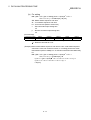
• SAFETY PRECAUTIONS •
(Read these precautions before using.)
When using Mitsubishi equipment, thoroughly read this manual and the associated manuals introduced in
this manual.
Also pay careful attention to safety and handle the module properly. These precautions apply only to
Mitsubishi equipment. Refer to the user’s manual of the CPU module to use for a description of the PLC
system safety precautions.
These • SAFETY PRECAUTIONS • classify the safety precautions into two categories: "DANGER" and
"CAUTION".
DANGER
Procedures which may lead to a dangerous condition and cause death
or serious injury if not carried out properly.
CAUTION
Procedures which may lead to a dangerous condition and cause
superficial to medium injury, or physical damage only, if not carried out
properly.
Depending on circumstances, procedures indicated by ! CAUTION may also be linked to serious
results.
In any case, it is important to follow the directions for usage.
Store this manual in a safe place so that you can take it out and read it whenever necessary. Always
forward it to the end user.
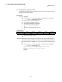
[DESIGN PRECAUTIONS]
!
DANGER
• Read Chapter 5 in this manual carefully for status of each station when the PC CPU has
stopped its operation and when a communication error occurred in the data link.
Configure an interlocking circuit in a sequence program using the communication status
information (SB, SW) so that the safety of the overall system is always maintained.
Accident may occur due to output error or malfunctioning.
• An error is not detected by the master station nor local station when a station specified as an
error-invalid station is in a communication error status.
!
CAUTION
• Do not bundle, on install, the control cables and communication cables with, or near, main circuit
and power cables. Keep them at least 100mm (3.9 inch) away from such cables. Noise may
cause erroneous operation.
A-1
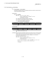
[INSTALLATION PRECAUTIONS]
!
CAUTION
• Use the PC in the environment given in the general specifications section of this manual. Using
the PC outside the range of the general specifications may result in electric shock, fire, or
erroneous operation or may damage or degrade the product.
• Insert the tabs at the bottom of the module into the holes in the base unit before installing the
module. (Modules in AnS series, make sure screws are securely tightened to base unit with
specified torques.)
Improper installation may cause erroneous operation, accidents, or the module to fall out.
• Do not directly touch the module's conductive parts or electronic components.
Doing so could cause malfunction or trouble in the module.
[PRECAUTIONS REGARDING WIRING]
!
DANGER
• Before beginning any installation or wiring work, make sure all phases of the power supply have
been obstructed from the outside. Failing to completely shut out the power supply phases could
cause electrical shock and/or damage to the product.
• Following installation or wiring work, when turning on the power supply and operating the
equipment, make sure the terminal cover provided as an accessory has been attached to the
product.
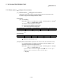
[WIRING PRECAUTIONS]
!
CAUTION
• Tighten the terminal screws by the specified torque.
Loose terminal screws may cause a short circuit or erroneous operation.
• Be sure that cuttings, wire chips, or other foreign matter do not enter the module.
Foreign matter may start a fire or cause an accident or erroneous operation.
• Be sure to fix communication cables and power cables leading from the module by placing them
in the duct or clamping them. Cables not placed in the duct or without clamping may hang or
shift, allowing them to be accidentally pulled, which may result in a malfunction or damage to the
module and cable.
• When detaching the communication cable or power cable from the module, do not pull the cable
portion. For cables with connectors, hold the connector at the junction to the module, then
detach it. For connectors without connectors, first loosen the screw at the junction, then detach
the cable.
Pulling the cable portion while it is connected to the module may cause a malfunction or damage
to the module and cable.
A-2
[STARTING AND MAINTENANCE PRECAUTIONS]
!
CAUTION
• Do not touch live terminals.
It may cause erroneous operation.
• Turn off the power before cleaning the module or retightening the screws. Doing this work while
the power is on may damage the module or cause erroneous operation.
• Do not disassemble or rebuild the module.
It may cause accidents, erroneous operation, injury, or fire.
• Turn off the power before mounting and dismounting the module.
Mounting or dismounting the module whhile the power is on may damage the module or cause
erroneous operation.
[DISPOSAL PRECAUTIONS]
!
CAUTION
• When disposing of this product, handle it as industrial waste.
A-3
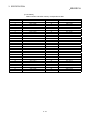
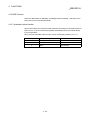
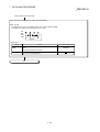
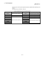
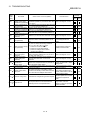
Revisions
The manual number is noted at the lower left of the back cover.
Print Date
Manual Number
Nov. 1996
Jan. 1997
IB (NA)-66721-A
IB (NA)-66721-B
Revision
First printing
Addition
Section 3.2.1, 4.12.3, 13.2
Correction
Chapter 1, Section 1.1, 3.2, 3.4.1, 7.3, 7.6.3, 8.3.2, 13.1, 13.5.8
Aug. 1997
IB (NA)-66721-C
Addition
Section 1.1, 5.3.4, 5.4, Chapter 14, 15, 16
Correction
Section 1.4, 1.5, 2.1, 2.2.1, 2.2.3, 3.2, 3.2.1, 3.4.1, 3.4.2, 5.1, 7.1, 7.2.1,
7.3, 7.5, 7.6.1, 7.6.3, 7.6.4, 7.7.1, 7.7.2, 7.8
Jan. 1998
IB (NA)-66721-D
Addition model
Section 1.4, 2.2.3
Correction
Section 1.1, 3.3, 3.4.1, 3.5.1, 3.5.2, 4.3, 4.5, 5.2, 7.6.4, 13.1, Chapter
14, 15.1, 15.2.1, 15.6, 15.6.1, 15.6.3, 15.6.4, 15.6.5, 15.6.10, 16.2.3,
App2
Mar. 2000
IB (NA)-66721-E
Addition model
Section 2.2.3
Addition
Section 7.6, 15.7
Correction
SAFETY PRECAUTIONS, Section 1.1, 1.5, 3.3, 3.5.1, 5.1, 5.2, 5.4.3,
7.3, 7.5, 8.3.2, 10.2.2, 12.2.2, 13.3, Chapter 14, Section 15.1, 15.2.1,
15.5.2, 15.5.4, 15.5.5, 15.6, 15.8, Chapter 16
Jul. 2000
IB (NA)-66721-F
Addition
Section 2.2.4, 3.2.2
Correction
Section 1.4, 2.2.1, 3.2, 3.2.1, 3.3, 3.4.2, 3.5.1, 7.3, 7.6.2, 7.7.4, 8.3.1,
9.1.1, 10.1.1, 10.2.2, 11.1.1, 11.1.2, 12.1.1, 12.1.4, 15.2.1, App1.1,
App1.2
Jul. 2001
IB (NA)-66721-G
Addition
Section 8.2
Correction
Section 2.2.3, 3.4.1, 3.4.2, 4.12.1, 5.4, 5.4.1, 5.4.2, 5.4.3, 7.2.1, 7.3, 7.5,
8.4.2, 9.1.1, 9.2.1, 10.1.1, 10.2.1, 11.1.1, 11.1.2, 11.2.1, 12.1.1, 12.1.4,
12.2.1, 13.1, 13.3, 13.4.2, 13.4.3, Chapter 14, Section 15.1, 15.2.1, 15.6,
15.7.1
Japanese Manual Version SH-3603-I
This manual does not imply guarantee or implementation right for industrial ownership or implementation of other rights.
Mitsubishi Electric Corporation is not responsible for industrial ownership problems caused by use of the contents of this
manual.
1996 Mitsubishi Electric Corporation
A-4
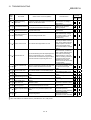
Print Date
Manual Number
Revision
Jul. 2002
IB (NA)-66721-H
Correction
Section 2.2.3, 3.3, 3.4.2, 4.10, 8.1, 13.3, 15.6
Oct. 2002
IB (NA)-66721-I
Correction
Section 3.1, 3.5.2
A-5
INTRODUCTION
Thank you for choosing a Mitsubishi MELSEC-A Series General Purpose Programmable Controller.
Before using your new PC, please read this manual thoroughly to gain an understanding of its functions so you
can use it properly.
Please forward a copy of this manual to the end user.
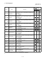
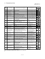
Table of Contents
SAFETY PRECAUTIONS..............................................................................................................................A- 1
Revisions ........................................................................................................................................................A- 4
About This Manual .........................................................................................................................................A-12
1. Overview..........................................................................................................................................1- 1 to 1-14
1.1 How to Use This Manual......................................................................................................................... 1- 3
1.2 Characteristics......................................................................................................................................... 1- 4
1.3 Communication Overview....................................................................................................................... 1- 9
1.3.1 Communication between the master station and remote I/O station ............................................. 1- 9
1.3.2 Communication between the master station and remote device station ....................................... 1-10
1.3.3 Communication between the master station and local station ....................................................... 1-11
1.3.4 Compound system communication ................................................................................................. 1-12
1.4 Number of Occupied Stations and Station Number, Number of Unit and Number of Stations............ 1-13
1.5 Abbreviations and Special Terms........................................................................................................... 1-14
2. System Configuration......................................................................................................................2- 1 to 2- 8
2.1 Total Configuration.................................................................................................................................. 22.2 Applicable System .................................................................................................................................. 22.2.1 Applicable CPU and number of cards that can be installed ........................................................... 22.2.2 Precautions when configuring a system.......................................................................................... 22.2.3 List of system equipment restricted by master/local module versions ........................................... 22.2.4 About Ver. 1.10................................................................................................................................. 2-
1
2
2
3
6
7
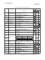
3. Specification ....................................................................................................................................3- 1 to 3-36
3.1 General Specification.............................................................................................................................. 3- 1
3.2 Performance Specifications .................................................................................................................... 3- 2
3.2.1 Maximum overall cable distance (for Ver. 1.00).............................................................................. 3- 3
3.2.2 Maximum overall cable distance (for Ver. 1.10).............................................................................. 3- 5
3.3 CC-Link Dedicated Cable ....................................................................................................................... 3- 6
3.4 I/O Signals to the PC CPU...................................................................................................................... 3- 7
3.4.1 I/O signal list ..................................................................................................................................... 3- 7
3.4.2 I/O signal details ............................................................................................................................... 3- 9
3.5 Buffer Memory......................................................................................................................................... 3-18
3.5.1 Buffer memory list ............................................................................................................................ 3-18
3.5.2 Buffer memory details ...................................................................................................................... 3-20
A-6
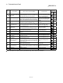
4. Functions .........................................................................................................................................4- 1 to 4-30
4.1 Function List ............................................................................................................................................ 4- 1
4.2 Communication Between the Master Station and Remote I/O Station ................................................. 4- 2
4.3 Communication Between the Master Station and Remote Device Station........................................... 4- 4
4.4 Communication Between the Master Station and Local Station ........................................................... 4-10
4.5 Communication in Compound Systems................................................................................................. 4-16
4.6 Reserved Station Function ..................................................................................................................... 4-22
4.7 Error Invalid Station Function ................................................................................................................. 4-23
4.8 Data Link Status Setting when the Master Station PC CPU has an Error............................................ 4-24
4.9 Setting the Status of Input Data from a Data Link Faulty Station.......................................................... 4-25
4.10 Module Reset Function from a Sequence Program ............................................................................ 4-26
4.11 Data Link Stop/Restart.......................................................................................................................... 4-27
4.12 RAS Function ........................................................................................................................................ 4-28
4.12.1 Automatic return function ............................................................................................................... 4-28
4.12.2 Slave station cut-off function.......................................................................................................... 4-29
4.12.3 Station number overlap checking function .................................................................................... 4-30
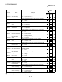
5. Data Link Processing Time.............................................................................................................5- 1 to 5-24
5.1 Status of Each Station when an Error has Occurred............................................................................. 5- 1
5.2 Link Scan Time ....................................................................................................................................... 5- 4
5.3 Transmission Delay Time ....................................................................................................................... 5- 5
5.3.1 Master station remote I/O station................................................................................................ 5- 5
5.3.2 Master station remote device station .......................................................................................... 5- 7
5.3.3 Master station local station.......................................................................................................... 5-11
5.3.4 Master station intelligent device station ...................................................................................... 5-15
5.4 Dedicated Instruction Processing Time.................................................................................................. 5-16
5.4.1 Master station
local station ......................................................................................................... 5-16
5.4.2 Local station
local station............................................................................................................ 5-20
intelligent device station ..................................................................................... 5-22
5.4.3 Master station
6. Parameter Setting ...........................................................................................................................6- 1 to 6-10
6.1 Procedure from Parameter Setting to Data Link Startup....................................................................... 6- 1
6.1.1 Relationship between buffer memory, E2PROM and internal memory.......................................... 6- 1
6.1.2 Procedure from parameter setting to data link start........................................................................ 6- 3
6.2 Parameter Settings ................................................................................................................................. 6- 4
6.3 Setting from a Sequence Program ......................................................................................................... 6- 5
A-7
7. Data Link Procedure........................................................................................................................7- 1 to 7-22
7.1 Data Link Procedure ............................................................................................................................... 7- 1
7.2 Installation and Setting............................................................................................................................ 7- 2
7.2.1 Precautions when handling the module .......................................................................................... 7- 2
7.2.2 Setting environment ......................................................................................................................... 7- 2
7.3 Name of Each Part and Settings ............................................................................................................ 7- 3
7.4 Checking Module Condition (Hardware Test)........................................................................................ 7- 7
7.5 Module Wiring with CC-Link Dedicated Cable....................................................................................... 7- 9
7.6 T-Branch Connection with the CC-Link Dedicated Cable ..................................................................... 7-11
7.6.1 T-Branch system configuration ........................................................................................................ 7-11
7.6.2 T-Branch communication specifications list .................................................................................... 7-11
7.7 Switch Settings........................................................................................................................................ 7-13
7.7.1 Station number setting (master station, local station and remote station) ..................................... 7-13
7.7.2 Mode setting ..................................................................................................................................... 7-15
7.7.3 Transmission speed setting ............................................................................................................. 7-15
7.7.4 Condition setting............................................................................................................................... 7-16
7.8 Checking the Connection Condition (Line Test) .................................................................................... 7-17
7.8.1 Checking connection and communication status with remote station/local station
(Line Test 1)...................................................................................................................................... 7-17
7.8.2 Checking connection and communication status with specific remote
station/local station (Line Test 2) ..................................................................................................... 7-19
7.9 Checking Parameters (Parameter Confirmation Test) .......................................................................... 7-21
8. Programming ...................................................................................................................................8- 1 to 8-22
8.1 Precautions when Programming ............................................................................................................ 8- 1
2
8.2 Precautions for Registering Parameters to E PROM............................................................................. 8- 3
8.2.1 Target module and versions ............................................................................................................ 8- 3
8.2.2 Precautions....................................................................................................................................... 8- 3
2
8.2.3 Program for registering parameters to E PROM............................................................................ 8- 4
8.3 Programming Procedure........................................................................................................................ 8- 6
8.3.1 Communication between the master station and remote I/O station ............................................. 8- 6
8.3.2 Communication between the master station and remote device station ....................................... 8- 7
8.3.3 Communication between the master station and local station ....................................................... 8- 8
8.3.4 Communication in a compound system .......................................................................................... 8-10
8.4 Link Special Relay/Register (SB/SW) .................................................................................................... 8-12
8.4.1 Link special relay (SB) ..................................................................................................................... 8-12
8.4.2 Link special register (SW) ................................................................................................................ 8-16
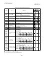
9. Communication Between the Master Station and the Remote I/O Station ...................................9- 1 to 9-12
9.1 System Configuration.............................................................................................................................. 99.1.1 Setting of the master station ............................................................................................................ 99.1.2 Setting of the remote I/O station ...................................................................................................... 99.2 Creating a Program................................................................................................................................. 99.2.1 Program for parameters................................................................................................................... 99.2.2 Communication program.................................................................................................................. 9A-8
1
2
3
4
4
7
9.3 Performing the Data Link ........................................................................................................................ 9-10
9.3.1 Confirming the operation by LED display........................................................................................ 9-10
9.3.2 Confirming the operation by the program........................................................................................ 9-11
10. Communication Between the Master Station and the Remote Device Station...................... 10- 1 to 10-14
10.1 System Configuration.......................................................................................................................... 10- 1
10.1.1 Setting of the master station ........................................................................................................ 10- 2
10.1.2 Setting of the remote device station ............................................................................................ 10- 3
10.2 Creating a Program............................................................................................................................. 10- 4
10.2.1 Program for parameters............................................................................................................... 10- 4
10.2.2 Communication program ............................................................................................................. 10- 7
10.3 Performing the Data Link .................................................................................................................... 10-12
10.3.1 Confirming the operation by LED display.................................................................................... 10-12
10.3.2 Confirming the operation by the program.................................................................................... 10-13
11. Communication Between the Master Station and the Local Station ...................................... 11- 1 to 11-14
11.1 System Configuration.......................................................................................................................... 11- 1
11.1.1 Setting of the master station ........................................................................................................ 11- 2
11.1.2 Setting of the local station............................................................................................................ 11- 3
11.2 Creating a Program............................................................................................................................. 11- 4
11.2.1 Program for the mater station ...................................................................................................... 11- 4
11.2.2 Local station program .................................................................................................................. 11-10
11.3 Performing the Data Link .................................................................................................................... 11-12
11.3.1 Confirming the operation by LED display.................................................................................... 11-12
11.3.2 Confirming the operation by the program.................................................................................... 11-13
12. Communication in the Compound System.............................................................................. 12- 1 to 12-16
12.1 System Configuration.......................................................................................................................... 12- 1
12.1.1 Setting of the master station ........................................................................................................ 12- 2
12.1.2 Setting of the remote I/O station .................................................................................................. 12- 3
12.1.3 Setting of the remote device station ............................................................................................ 12- 3
12.1.4 Setting of the local station............................................................................................................ 12- 4
12.2 Creating a Program............................................................................................................................. 12- 5
12.2.1 Program for the master station .................................................................................................... 12- 5
12.2.2 Local station program .................................................................................................................. 12-13
12.3 Performing the Data Link .................................................................................................................... 12-14
12.3.1 Confirming the operation by LED display.................................................................................... 12-14
12.3.2 Confirming the operation by the program.................................................................................... 12-16
A-9
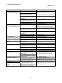
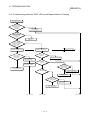
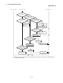
13. Troubleshooting........................................................................................................................ 13- 1 to 13-18
13.1 Verification when a Trouble Occurs ................................................................................................... 13- 1
13.2 Troubleshooting when the "ERR" LED on the Master Station is Flashing........................................ 13- 4
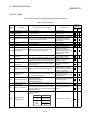
13.3 Error Codes ......................................................................................................................................... 13- 6
13.4 LED Display Status ............................................................................................................................. 13-12
13.4.1 When data link is normal.............................................................................................................. 13-12
13.4.2 When a cable is disconnected..................................................................................................... 13-12
13.4.3 When a cable is shorted .............................................................................................................. 13-13
13.4.4 When the link is stopped at the master station ........................................................................... 13-13
13.4.5 When power supply to a remote I/O station is turned off............................................................ 13-14
13.4.6 When the power supply to a remote device station is turned off................................................ 13-14
13.4.7 When the power supply to the local station (PC CPU) is turned off........................................... 13-15
13.4.8 When the station numbers are duplicate..................................................................................... 13-15
13.4.9 When the transmission speed is set incorrectly.......................................................................... 13-16
13.4.10 When the switch setting is changed during data link ................................................................ 13-16
13.4.11 When data link is started with the switch set outside the range............................................... 13-17
13.4.12 When the remote I/O station is not set by the parameter (i.e., is set as reserved).................. 13-17
13.4.13 When the remote device station is not set by the parameter (i.e., is set as reserved)............ 13-18
13.4.14 When the local station is not set by the parameter (i.e., is set as reserved) ........................... 13-18
14. Overview (Function Version B or Later) .................................................................................. 14- 1 to 14- 2
15. Functions (Function Version B or Later).................................................................................. 15- 1 to 15-16
15.1 List of Functions .................................................................................................................................. 15- 1
15.2 Parameter Registration Function........................................................................................................ 15- 1
15.2.1 Network parameters..................................................................................................................... 15- 1
15.2.2 Automatic refresh parameters ..................................................................................................... 15- 3
15.3 Automatic Refresh Function ............................................................................................................... 15- 3
15.4 Scan Synchronous Function............................................................................................................... 15- 4
15.4.1 Synchronous mode ...................................................................................................................... 15- 4
15.4.2 Asynchronous mode .................................................................................................................... 15- 5
15.5 Standby Master Function.................................................................................................................... 15- 6
15.5.1 Operation overview ...................................................................................................................... 15- 6
15.5.2 Settings on using the standby master function ........................................................................... 15- 7
15.5.3 Special link relays/resisters (SB,SW) relating to the standby master function .......................... 15- 8
15.5.4 Notes on using the standby master function............................................................................... 15- 9
15.5.5 Program example on using the standby master function ........................................................... 15-10
15.6 Dedicated Instructions ........................................................................................................................ 15-11
15.7 Remote I/O Net Mode......................................................................................................................... 15-12
15.7.1 Features........................................................................................................................................ 15-12
15.7.2 Software version corresponding to master module and its CPU................................................ 15-12
15.7.3 Set items....................................................................................................................................... 15-12
15.7.4 Link scan time .............................................................................................................................. 15-13
15.7.5 Precaution .................................................................................................................................... 15-13
A - 10
15.8 Temporary Error Invalid Station Specification Function .................................................................... 15-14
15.8.1 I/O status of the temporary error invalid station specification..................................................... 15-14
15.8.2 Special link relay/registers (SB,SW) relating to the temporary error invalid station
specification function.................................................................................................................... 15-14
15.8.3 Execution procedure for the temporary error invalid station specification function ................... 15-16
16. Communication with the Intelligent Device (Function Version B or Later) ............................. 16- 1 to 16- 2
Appendix ..............................................................................................................................................A- 1 to A- 5
Appendix 1 External Dimensions Diagram...................................................................................................A1.1 AJ61BT11 ............................................................................................................................................A1.2 A1SJ61BT11 .......................................................................................................................................AAppendix 2 Parameter Setting Sheet ...........................................................................................................A-
A - 11
1
1
2
3
About This Manual
The following are manuals related to this product.
Request for the manuals as needed according to the chart below.
Related Manuals
Manual No.
(Type code)
Manual Name
AnSHCPU/AnACPU/AnUCPU Programing Manual (Dedicated instructions)
Describes the commands that were extended for AnSHCPU/AnACPU/AnUCPU.
(Sold separately)
A - 12
IB-66251
(13J742)
1 OVERVIEW
MELSEC-A
1. Overview
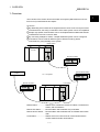
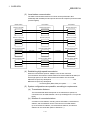
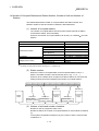
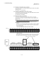
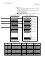
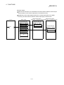
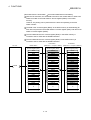
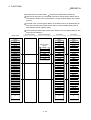
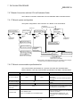
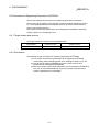
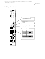
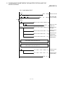
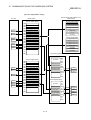
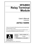
The overview of the Control & Communication Link system (abbreviated as CC-Link
from here on) is described in this chapter.
CC-Link is...
1 By distributing each module to the equipment device such as the conveyor line and
machine devices, the wiring conservation of the entire system can be accomplished.
2 Simple, high-speed communication can be accomplished with modules that handle
on/off data such as I/O or numeric data.
3 By connecting multiple PC CPUs, a simple distributed system can be configured.
4 Connections can be made to different types of devices made by partner
manufacturers, giving flexibility to the system.
Master station
PC CPU
Remote I/O station
Partner manufacturer's
product
Remote device station
CC - Link system
Remote I/O station
Local station
PC CPU
Master station...................Station which controls the remote I/O station, remote device
station, and local stations
Remote I/O station ...........Remote station which handles only on/off data
Remote device station .....Remote station which handles both on/off data and numeric
data
Local station .....................Station which has a CPU and can communicate with the
master station and other local stations
1-1
1
1 OVERVIEW
MELSEC-A
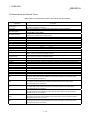
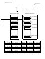
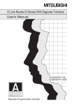
After unpacking, please check to make sure the following components have been
included.
Product name
AJ61BT11 main unit
AJ61BT11 CC-Link System Master·Local
Module User's Manual (Hardware)
AJ61BT11 Control & Communication Link
Terminating resistance 110 Ω, 1/2 W
System Master·Local Module
(All brown)
Terminating resistance 130 Ω, 1/2 W
(Brown, orange, brown)
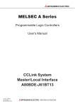
A1SJ61BT11 main unit
A1SJ61BT11 CC-Link System
Master·Local Module User's Manual
(Hardware)
A1SJ61BT11 Control & Communication
Link System Master·Local Module
Terminating resistance 110 Ω, 1/2 W
(All brown)
Terminating resistance 130 Ω, 1/2 W
(Brown, orange, brown)
1-2
Quantity
1
1
2
2
1
1
2
2
1 OVERVIEW
MELSEC-A
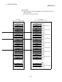
1.1 How to Use This Manual
The master·local module has the following functions added from the function version B
or later. The detailed descriptions of the additional functions are provided in Chapter 14
or later.
(1) Scan synchronous function
Link scan can be executed synchronized with the sequence scan.
(2) Standby master function
With this function, the data link can be continuously executed even if an error
occurs in the master station, by automatically switching to the standby master
station.
(3) Dedicated instructions
Transient transmission with the intelligent device and local station is possible.
In addition, read/write of data with handshake to/from the remote device is
feasible.
(4) Temporary error invalid station specification function
By specifying the corresponding remote station as a temporary error invalid
station, an error is not detected even if the module is replaced while in
communication.
(5) Parameter registration function
Parameters such as total number of connected stations and station information
can be set using dedicated instructions.
(6) Automatic refresh function
Data transferred by cyclic transmissions, such as RX and RY, can be refreshed
by the END processing to a desired device, when set up with the dedicated
instruction.
(7) Dedicated instruction (software version J or later)
Reading and writing of device with respect to the CPU of the specified station are
possible.
(8) Remote I/O net mode (applicable to software version P or later)
When the system is configured only with the master station and remote I/O
stations, if the remote I/O net mode is used, the setting of the network
parameters will be unnecessary and the link scanning time will be shortened.
1-3
1 OVERVIEW
MELSEC-A
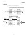
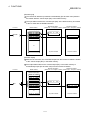
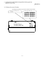
1.2 Characteristics
The characteristics of the CC-Link are described below:
(1) Remote I/O station communication
The communication is performed with only on/off data (remote input RX and
remote output RY).
Master station
Remote I/O station
Remote input
(RX)
Link scan
Remote output
(RY)
Link scan
Input
Output
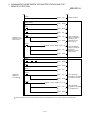
(2) Remote device station communication
The communication is performed with on/off data (remote input RX and remote
output RY) and numeric data (remote register).
Master station
A/D conversion
completion flag
Remote input
(RX)
Link scan
Remote input
(RX)
Remote output
(RY)
Link scan
Remote output
(RY)
Remote register
(RWw)
Link scan
Remote register
(RWw)
Remote register
(RWr)
Link scan
Remote register
(RWr)
Offset•gain selection
A/D conversion
enable/disable specification
TO
Digital output value
FROM
Remote device station
1-4
Analog voltage
1 OVERVIEW
MELSEC-A
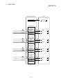
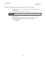
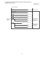
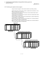
(3) Local station communication
The data communication between PC CPUs can be performed in N:N
relationship with bit data (remote input RX and remote output RY) and word data
(remote register)
Master station
Local station
Local station
Remote input (RX)
Remote output (RY)
Remote output (RY)
Link scan
Link scan
Remote output (RY)
Remote input (RX)
Link scan
Remote register (RWw)
Remote input (RX)
Link scan
Remote register (RWr)
Link scan
Remote register (RWr)
Remote register (RWr)
Link scan
Remote register (RWw)
Link scan
Remote register (RWw)
Link scan
(4) Establishing high-speed transmission
When the transmission speed of 10Mbps is set, the link scan time
(communication time with the master station and remote station/local station) is
still at high speed, even when the maximum 64 stations are connected.
Remote I/O (RX, RY) 2048 points ..................................................... 4 ms
Remote I/O (RX, RY) 2048 points
+ remote register (RWw, RWr) 512 points ................ 7 ms
(5) System configurations are possible, according to requirements.
(a) Transmission distance
The total extended distance depends on the transmission speed, but
connections can be made between 100 m (at 10 Mbps) and 1.2 km (at 156
kbps).
(b) Number of connected stations
A maximum of 64 stations, including remote I/O stations, remote device
stations, and local stations can be connected to one master station.
Up to 64 remote I/O stations, 42 remote device stations, and 26 local
stations can be connected. (Refer to Section 2.1.)
1-5
1 OVERVIEW
MELSEC-A
(6) Link points
2048 points of remote input (RX), 2048 points of remote output (RY), and 512
points of remote register (RW) can be used for communication in one system.
For one remote station or local station, 32 points of remote input (RX), 32 points
of remote output (RY), and 8 points of remote register (RW) (RWw: 4 points,
RWr: 4 points) can be handled.
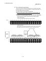
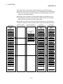
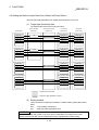
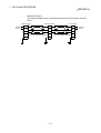
(7) System down prevention (Station cutoff function)
Because the system employs the bus method, even if there is a remote station or
local station which goes down due to power off, etc., it won't affect the
communication with other functioning remote/local stations.
Also, for the module using with the 2-piece terminal block, the module can be
replaced during data link.
Master
station
Station No.1
Station No.3
Station No.4
Station No.7
Local station
(occupies 1
station)
Local station
(occupies 4
stations)
Remote station
Remote station
(occupies 2 stations) (occupies 1 station)
Station No.5
Remote station
(occupies 2 stations)
Data link continues
Faulty
station
Master
station
Station No.1
Station No.3
Remote station
Remote station
(occupies 2 stations) (occupies 1 station)
1-6
Station No.4
Station No.7
Local station
(occupies 1
station)
Local station
(occupies 4
stations)
Station No.5
Remote station
(occupies 2 stations)
1 OVERVIEW
MELSEC-A
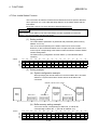
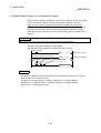
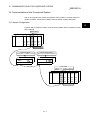
(8) Reserved station function
By setting the station which is not actually connected (station planned for
connection in the future) as a reserved station, the station will not be handled as
a faulty station.
Station planned for
connection in the future
(Reserved station)
Station No.4
Master
station
Station No.1
Local station
(occupies 4
stations)
Station No.3
Remote station
Remote station
(occupies 2 stations) (occupies 1 station)
Station No.8
Remote station
(occupies 1 station)
(Reserved station)
Station No.9
Remote station
(occupies 1 station)
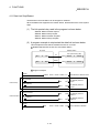
(9) Error invalid station function
A station that cannot perform data links because the power is turned off, etc., can
be handled as other than a "data-link faulty station" on the master station and the
local station.
Be careful, however, for errors will not be detected.
Stations to be set as error invalid stations
Master
station
Station No.1
Station No.3
Station No.4
Station No.7
Local station
(occupies 1
station)
Local station
(occupies 4
stations)
Station No.5
Remote station
(occupies 2 stations)
Remote station
Remote station
(occupies 2 stations) (occupies 1 station)
Station No.4
Station No.7
Local station
(occupies 1
station)
Local station
(occupies 4
stations)
Does not result as a data-link faulty station.
Master
station
Station No.1
Station No.3
Remote station
Remote station
(occupies 2 stations) (occupies 1 station)
1-7
Station No.5
Remote station
(occupies 2 stations)
1 OVERVIEW
MELSEC-A
(10) Parameter registration to the E2PROM
By registering the parameters to the E2PROM, the parameter settings do not
have to be performed at each master station startup (power off on).
Because this is the E2PROM, parameters are stored even if the module's power
is turned off.
PC CPU
Master station
2
2
E PROM
SET YnA
Buffer memory
1
TO
Parameter
information area
3
SET Yn8
Internal memory
The data link is executed using the parameters
registered in the internal memory.
(11) Data-link status setting for when a master station PC CPU error
occurs
The data-link status can be set (stop/continue) to either stop or continue for when
a "operation stop error" occurs at the master station's PC CPU, such as SP.
UNIT ERROR.
The data link between local stations can be continued.
"Operation continue errors" such as a BATTERY ERROR continue the data link
regardless of the setting.
(12) Input data from data-link faulty station status setting
The data input (received) from the data-link faulty station can be cleared or kept
(status right before an error is caused).
(13) Module reset function from the sequence program
When the switch setting is changed or an error occurs in the module, the module
can be reset from the sequence program without resetting the PC CPU.
(This excludes when the module has a module faulty (Xn0 is on).)
(14) RAS function
(a) Automatic return function
When a station is disconnected from the link due to power off, etc., and
returns to the normal status, the station can join the data link again
automatically.
(b) Link status check
Using the link special relay (SB) and link special register (SW) in the buffer
memory, the current data-link status can be checked.
(c) Diagnosis function
Using the switch setting, the hardware and cable conditions can be
checked.
1-8
1 OVERVIEW
MELSEC-A
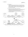
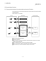
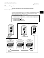
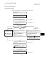
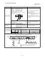
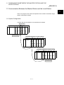
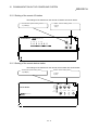
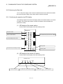
1.3 Communication Overview
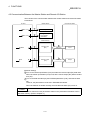
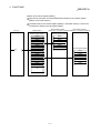
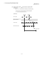
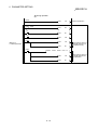
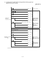
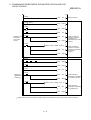
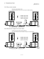
1.3.1 Communication between the master station and remote I/O station
The overview of the communication between the master station and remote I/O station
is described below.
Refer to Section 4.2 for details.
PC CPU
Master station
1
SET Yn0
2
SET Yn6
Remote I/O station
Refresh specification
Data link startup
Buffer memory
4
FROM
3
Remote input
(RX)
Link scan
Remote output
(RY)
Link scan
Input
6
5
TO
Output
Turn on the refresh specification
Startup the data link.
3 By the link scan, the remote I/O station's input information is stored in the master
station's remote input (RX).
4 By the FROM instruction, read from the remote input (RX).
5 By the TO instruction, write the on/off data to the remote output (RY).
6 By the link scan, the remote I/O station's output is turned on/off.
1
2
1-9
1 OVERVIEW
MELSEC-A
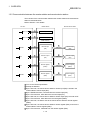
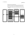
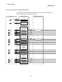
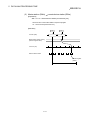
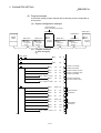
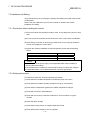
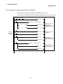
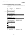
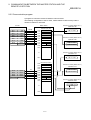
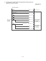
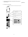
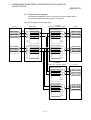
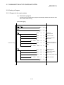
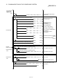
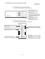
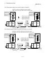
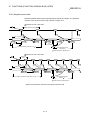
1.3.2 Communication between the master station and remote device station
The overview of the communication between the master station and remote device
station is described below.
Refer to Section 4.3 for details.
PC CPU
Master station
1
SET Yn0
2
SET Yn6
Remote device station
Refresh specification
Data-link startup
Buffer memory
4
FROM
5
TO
7
TO
10
FROM
1
2
3
4
5
6
7
8
9
10
3
Remote input
(RX)
Link scan
Remote output
(RY)
Link scan
Remote input
(RX)
6
Remote output
(RY)
8
Remote register
(RWw)
Link scan
Remote register
(RWw)
9
Remote register
(RWr)
Link scan
Remote register
(RWr)
Turn on the refresh specification
Startup the data link.
By the link scan, the remote device station's remote input (RX) is stored in the
master station's remote input (RX).
By the FROM instruction, read data from the remote input (RX).
By the TO instruction, write data to the remote output (RY).
By the link scan, the remote device station's remote output (RY) is turned on/off.
By the TO instruction, write data to the remote register (RWw).
By the link scan, the data is sent to the remote device station's remote register
(RWw).
By the link scan, the remote device station's remote register (RWr) is sent to the
master station's remote register (RWr).
By the TO instruction, read data from the remote register (RWr).
1 - 10
1 OVERVIEW
MELSEC-A
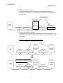
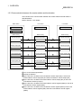
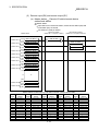
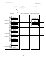
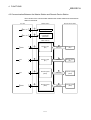
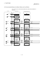
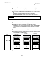
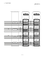
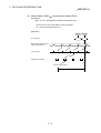
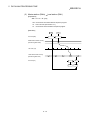
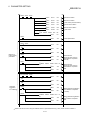
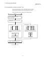
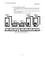
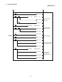
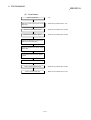
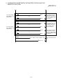
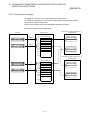
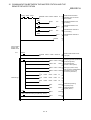
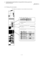
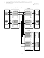
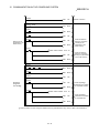
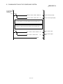
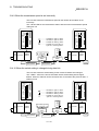
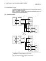
1.3.3 Communication between the master station and local station
The overview of the communication between the master station and local station is
described below.
Refer to Section 4.4 for details.
Master station
Local station
Local station
1 Refresh specification
1 Refresh specification
1 Refresh specification
Buffer memory
Buffer memory
2 Data link startup
Buffer memory
Remote input (RX)
Remote output (RY)
Remote output (RY)
3
3
Link scan
Link scan
Remote output (RY)
Remote input (RX)
Remote input (RX)
4
4
Link scan
Link scan
Remote register (RWw)
Remote register (RWr)
Remote register (RWr)
5
5
Link scan
Link scan
Remote register (RWr)
Remote register (RWw)
Remote register (RWw)
6
6
Link scan
Link scan
Turn on the refresh specification.
Startup the data link.
3 By the link scan, the data in the local station's remote output (RY) is sent to the
master station's remote input (RX) and other local stations' remote output (RY).
4 By the link scan, the data in the master station's remote output (RY) is sent to all
local station's remote input (RY).
5 By the link scan, the data in the master station's remote register (RWw) is sent to all
local stations' remote register (RWr).
6 By the link scan, the data in the local station's remote register (RWw) is sent to the
master station's remote register (RWr) and other local stations' remote register
(RWw).
1
2
1 - 11
1 OVERVIEW
MELSEC-A
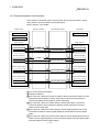
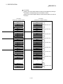
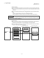
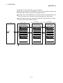
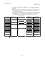
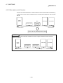
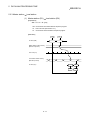
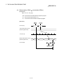
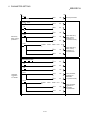
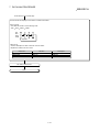
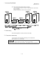
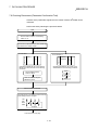
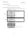
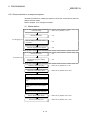
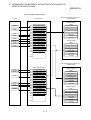
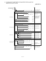
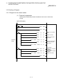
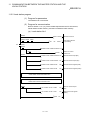
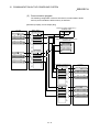
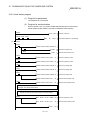
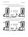
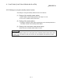
1.3.4 Compound system communication
The overview of compound system communication with remote I/O stations, remote
device stations, and local stations is described below.
Refer to Section 4.5 for details.
Master station
Remote I/O station
Remote device station
Local station
1 Refresh specification
1 Refresh specification
2 Data link startup
Buffer memory
Buffer memory
Remote input (RX)
3
Input
3
3
Remote output (RY)
Remote input (RX)
Remote output (RY)
4
Output
4
4
Remote input (RX)
Remote output (RY)
Remote register (RWw)
Remote register (RWr)
5
5
5
Remote register (RWw)
Remote register (RWr)
Remote register (RWw)
6
6
Remote register (RWr)
6
Turn on the refresh specification.
Startup the data link.
3 By the link scan, data in the remote I/O station's and remote device station's remote
input (RX) and local station's remote output (RY) is sent to the master station's
remote input (RX) and local station's remote output (RY).
4 By the link scan, data in the master station's remote output (RY) is sent to the
remote I/O station's and remote device station's remote output (RY) and local
station's remote input (RX).
5 By the link scan, data in the master station's remote register (RWw) is sent to the
remote device station's remote register (RWw) and local station's remote register
(RWr).
6 By the link scan, data in the remote device station's remote register (RWr) and local
station's remote register (RWw) is sent to the master station's remote register (RWr)
and local station's remote register (RWw).
1
2
1 - 12
1 OVERVIEW
MELSEC-A
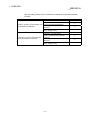
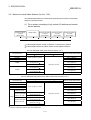
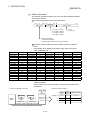
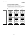
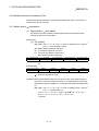
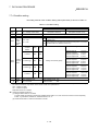
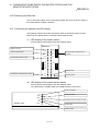
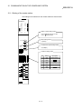
1.4 Number of Occupied Stations and Station Number, Number of Unit and Number of
Stations
The relationship between number of occupied station and station number, and
between number of units and number of stations is described below.
(1) Number of occupied stations
The number of occupied stations is fixed for each module (remote I/O station,
remote device station, and local station).
However, the number of occupied stations can be set (1 to 4 stations ) for local
stations.
Module
Remote I/O station (16 points and 32 points module)
AJ65BT-64AD
AJ65BT-64DAV
AJ65BT-64DAI
Remote device station
AJ65BT-D62
AJ65BT-D62D(S1)
A852GOT
Local station
AJ65BT-R2
Intelligent device station
AJ65BT-G4
AJ65BT-D75P2-S3
Number of occupied stations
1 station
2 stations
2 stations
2 stations
4 stations
2 or 4 stations
1 to 4 stations
1 station
1 station
4 stations
(changed by switch)
The AJ61BT11 of hardware version F or later and the A1SJ61BT11 of hardware version G or later are compatible with
this setting. For other than the above, the setting is 1 or 4 stations only.
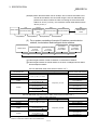
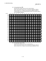
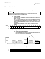
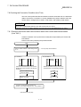
(2) Station number
When the number of occupied station for all connected stations is set to "1
station," the station number is set continuously from 1 (e.g. 1, 2, 3,... ).
However, when a station which occupies more than 2 stations is connected, the
setting must be performed considering the number of occupied stations.
Station No.1 Station No.2 Station No.3 Station No.4 Station No.5 Station No.6 Station No.7 Station No.8 Station No.9
Master
station
Station No.1
Station No.3
Remote station
(occupies 2 stations)
Remote station
(occupies 1 station)
Station No.4
Station No.9
Local station
(occupies 4
stations)
Local station
(occupies 1
station)
Station No.8
Remote station
(occupies 1 station)
(3) Number of units and number of stations
Number of units is a physical module count.
Number of stations is a number of occupied stations for each module as stated in
(1).
In the system configuration example in (2), the number of units is 5 and number
of stations is 9.
1 - 13
1 OVERVIEW
MELSEC-A
1.5 Abbreviations and Special Terms
Abbreviations and special terms used in this manual are shown below:
Abbreviation and
special term
Master station
Local station
Remote I/O station
Remote device station
Remote station
Intelligent device station
Master·local module
Master module
Local module
Remote module
Intelligent module
Remote I/O net mode
Remote net mode
I/O mode
Intelligent mode
Cycric transmission
Transient transmission
AnSCPU
AnCPU
AnNCPU
AnACPU
A2ASCPU
AnUCPU
Q2ASCPU
QnACPU
SB
SW
RX
RY
RWw
RWr
Description
Station which controls remote stations and local stations.
One station is required for one system.
Station with CPU which can communicate with master station and other local stations.
Remote station which deals with bit information only.
(AJ65BTB - , AJ65BTC - )
Remote station which deals with bit information and word information.
(AJ65BT-64AD, AJ65BT-64DAV, AJ65BT-64DAI)
General name for remote I/O station and remote device station. Controlled by a master station.
Station that can perform transient transmission (future plans). (Including local station)
General name for AJ61BT11 and A1SJ61BT11.
General name for AJ61BT11 and A1SJ61BT11 when they are used as master station.
General name for AJ61BT11 and A1SJ61BT11 when they are used as local station.
General name for AJ65BTB - , AJ65BTC - , AJ65BT-64AD, AJ65BT-64DAV and AJ65BT-64DAI.
Module that can perform transient transmission such as AJ65BT-R2
Mode which allows communication only with remote I/O stations without setting parameters.
Mode which allows communication with all stations for CC-Link.
In this mode the PC CPU cannot accept transient requests from an intelligent device station.
There is no limit in the number of installable modules.
In this mode the PC CPU can accept transient requests from an intelligent device station.
There is a limit in the number of installable modules.
This is the transmission method to update periodically contents of remote I/O and remote register.
This is the transmission method to communicate with any timing.
General name for A1SCPU, A1SCPU-S3, A1SJCPU, A1SJCPU-S3, A2SCPU, and A1SCPUC24-R2.
General name for A1CPU, A2CPU, A2CPUS1 and A3CPU.
General name for A1NCPU, A2NCPU, A2NCPUS1 and A3NCPU.
General name for A2ACPU, A2ACPUS1 and A3ACPU.
General name for A2ASCPU and A2ASCPUS1.
General name for A2UCPU, A2UCPUS1, A3UPU and A4UCPU.
General name for Q2ASCPU, Q2ASCPUS1, Q2ASHCPU and Q2ASHCPUS1.
General name for Q2ACPU, Q2ACPUS1, Q3ACPU and Q4ACPU.
Link special relay (for CC-Link)
This relay is used to store the state of data link as bit ON/OFF informationin in the master station,
and expressed by SB for convenience.
Link special resister (for CC-Link)
This resister is used to store the state of data link as word information in the master station,
and expressed by SW for convenience.
Remote input (for CC-Link)
This input is used to input ON/OFF information from the remote stations to the master station,
and expressed by RX for convenience.
Remote output (for CC-Link)
This output is used to output ON/OFF information from the master station to the remote stations,
and expressed by RY for convenience.
Remote resister (Write area for CC-Link)
This resister is used to output numerical data from the master station to the remote device stations,
and expressed by RWw for convenience.
Remote resister (Read area for CC-Link)
This resister is used to input numerical data from the remote device stations to the master station,
and expressed by RWr for convenience.
1 - 14
2 SYSTEM CONFIGURATION
MELSEC-A
2. System Configuration
The system configuration for the CC-Link is described in this chapter.
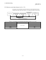
2.1 Total Configuration
A total of 64 remote I/O stations, remote device stations, local stations, standby master
stations, and intelligent device stations can be connected for one master station.
However, the following conditions must be satisfied:
(1) {(1×a)+(2×b)+(3×c)+(4×d)} 64
a : Number of modules occupying 1 station c : Number of modules occupying 3 stations
b : Number of modules occupying 2 stations d : Number of modules occupying 4 stations
(2) {(16×A)+(54×B)+(88×C)} 2304
A : Number of remote I/O stations 64
B : Number of remote device stations 42
C : Number of local stations, standby master stations, intelligent device stations
Maximum 26
Master station
A1SJ61BT11
AJ61BT11
Terminal resistor
(mandatory)
Local station
Local station
A1SJ61BT11
AJ61BT11
A1SJ61QBT11
AJ61QBT11
CC-Link dedicated cable
Maximum 26
Maximum 42
Maximum 64
Intelligent device station
Remote device station
Remote I/O station
RS-232C
Interface module
AJ65BT-R2
Analog-digital
conversion module
AJ65BT-64AD
Remote I/O module
AJ65BTB@@-@@
AJ65BTC@@-@@
Terminal resistor
(mandatory)
CC-Link dedicated cable
Total 64
2-1
26
2
2 SYSTEM CONFIGURATION
MELSEC-A
2.2 Applicable System
The applicable CPU modules and the precautions for system configuration are
described below.
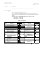
2.2.1 Applicable CPU and number of cards that can be installed
The applicable PC CPU, data link system/network system, and number of cards that
can be installed are shown in Table 2.1.
However, intelligent mode can not be used for future plan.
Table 2.1 Number of cards that can be installed
Installation area
A1SJ61BT11
Intelligent
mode
I/O mode
A0J2CPU
Unusable
A0J2HCPU
A1SCPU(S1)
A1SHCPU
A1SJCPU(S3)
A1SJHCPU
No restrictions
A1SCPUC24-R2
A2SCPU(S1)
A2SHCPU(S1)
A2ASCPU(S1/S30/S60)
Q2ASCPU(S1)
Q2ASHCPU(S1)
A1CPU
A2CPU(S1)
PC CPU A3CPU
A1NCPU
A2NCPU(S1)
A3NCPU
A3MCPU
A3HCPU
Unusable
A2ACPU(S1)
A3ACPU
A2UCPU(S1)
A3UCPU
A4UCPU
Q2ACPU(S1)
Q3ACPU
Q4ACPU
Q4ARCPU
MELSECNET remote I/O station
Unusable
MELSECNET/B remote I/O station
Unusable
AJ72LP25
Unusable
AJ72BR15
Data link
and network MELSECNET/10 AJ72QLP25
Unusable
remote I/O station AJ72QBR15
A1SJ72QLP25
No restrictions
A1SJ72QBR15
AJ61BT11
Intelligent
mode
I/O mode
Remarks
Unusable
2
2
No restrictions
1
1
2
2
6
6
Unusable
Unusable
2
No restrictions
Unusable
6
Unusable
Unusable
Unusable
Unusable
Unusable
Unusable
Unusable
Unusable
Unusable
No restrictions
2
Unusable
No restrictions
2
2
No restrictions
2
In the intelligent mode,
the following special
function modules
AD51(S3)
AD51H(S3)
AD57G(S3)
AJ71C21(S1):
In the BASIC
program mode
AJ71C23(S3)
AJ71C24(S3/S6/S8)
AJ71UC24
AJ71P41
AJ71E71(S1)
A1SJ71C24-R2
A1SJ71C24-PRF
A1SJ71C24-R4
A1SJ71UC24-R2
A1SJ71UC24-PRF
A1SJ71UC24-R4
A1SD51S
A1SJ71E71-B2(S3)
A1SJ71E71-B5(S3)
A0J2-C24
POINT
The module can be installed to any of the slots. However, the module cannot be installed to
the final slot of the 7th level of A3CPU extension.
2-2
2 SYSTEM CONFIGURATION
MELSEC-A
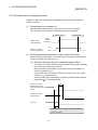
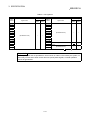
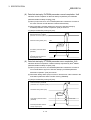
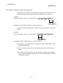
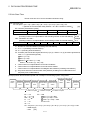
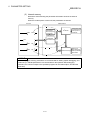
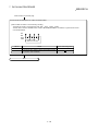
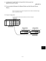
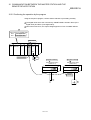
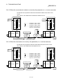
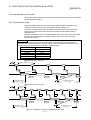
2.2.2 Precautions when configuring a system
Design the system with the following considerations to prevent mis-input from the
remote I/O module:
(1) During power on and power off
Start the data link after turning on the power for the remote I/O module.
Turn off power for the remote I/O module after stopping the data link.
Data link start
Master module
(Data-link status)
Data link stop
During
operation
During stop
ON
Remote I/O module
(Power supply status)
OFF
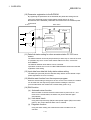
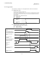
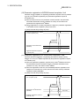
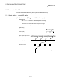
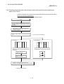
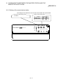
(2) During momentary power failure of the remote I/O module
When momentary power failure occurs with the power (24VDC) supplied to the
remote I/O module, mis-input may occur.
(a) Cause for mis-input due to a momentary power failure
The remote I/O module hardware uses the power after internally converting
the module power (24VDC) in to 5VDC.
When momentary power failure occurs with the remote I/O module, the
following condition occurs:
(Time for the 5VDC in the internal remote I/O module to turn off) > (input
module on off response time)
Therefore, mis-input is caused when a refresh is performed within the time
indicated by 1 ) in the diagram below.
1
Remote I/O module
(Module power supply
and input external-power
supply)
Remote I/O module
(Internal 5VDC)
Input (Xn)
Because the input external-power supply is turned off,
the input (Xn) turns off after the response time of input
module is turned off.
2-3
2 SYSTEM CONFIGURATION
MELSEC-A
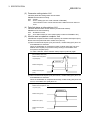
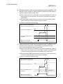
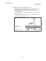
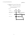
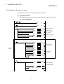
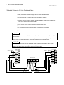
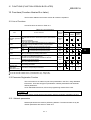
(b) Countermeasure for mis-input
Master module
Power supply module
For DC input
Wire the power supply cable for the power supply module, stabilized power,
and input/external-supply power of the AC input from the same power
source.
PC CPU
Remote I/O module
Module power supply
Input
external-supply
power
Master module
Power supply module
For AC input
Stabilized
24VDC
power supply
PC CPU
Remote I/O module
Module power supply
Stabilized
24VDC
power supply
Input
external-supply
power
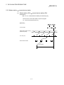
REMARK
When supplying power from one power source to multiple remote I/O modules, select the cable
and perform the wiring with considerations to the voltage decline from the cables.
Connections can be established if the remote I/O module's receiving port voltage is within the
specification range of the used remote I/O module.
Stabilized
power supply
Remote module
2-4
Remote module
2 SYSTEM CONFIGURATION
MELSEC-A
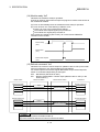
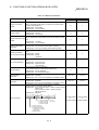
POINT
When using the functions described in Chapter 14 or later, use a system with the following
symbol (9707B or later) inscribed in the DATE column of the rated plate.
MITSUBISHI
PROGRAMMABLE CONTROLLER
CPU UNIT
MODEL A2USHCPU-S1
MAX 30kSTEP
DATE
9707
DATE
9707
B
B
MITSUBISHI ELECTRIC CORPORATION JAPAN
BD992D013H01
MITSUBISHI ELECTRIC
BD992D008H38
Manufactured
date
Function
version
Manufactured
date
Function
version
2-5
2 SYSTEM CONFIGURATION
MELSEC-A
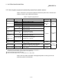
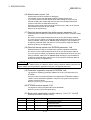
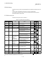
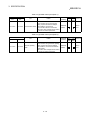
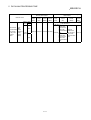
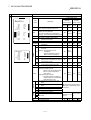
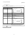
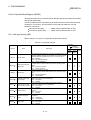
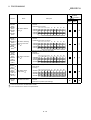
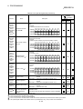
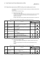
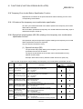
2.2.3 List of system equipment restricted by master/local module versions
Table 2.2 lists the CC-Link system equipment restricted by the function, hardware and
software versions of the master/local modules.
Table 2.2 System equipment list
Product name
Model
Description
A1SJ61BT11
AJ61BT11
Master·local module A1SJ61QBT11
AJ61QBT11
QJ61BT11
High-speed counter
module
Thermocouple
temperature input
module
Platinum
temperature
measuring resistor
Pt100
temperature input
module
ID interface module
RS-232C interface
module
Positioning module
Peripheral device
connection module
AJ65BT-D62 2
AJ65BT-D62D(S1)
2
Master·local module for AnS/A2AS series
Master·local module for A series
Master·local module for Q2AS series
Master·local module for QnA series
Master/local module for Q series
24 bit binary, 5/12/24VDC input type,
200kPPS, 2 channels
24 bit binary, differential input type,
400kPPS, 2 channels
Number of
occupied stations
When local
station 1 to 4
stations 1
For connecting thermocouple
Temperature input 8 channels
AJ65BT-68TD 2
AJ65BT-64RD3
For connecting Pt 100 (3 wire type)
2
Temperature input 4 channels
AJ65BT-64RD4
2
4 stations
Station type
Master or local
station
Remote device
staion
For connecting Pt 100 (4 wire type)
Temperature input 4 channels
AJ65BT-D32ID2
2 Number of readers/writers that can be connected is 2
Computer link function
AJ65BT-R2 2
RS-232C, 1 channel
For positioning control, Pulse chain output 2 axes
AJ65BT-D75P2-S3
(independent, simultaneous 2 axial, 2 axial linear
2
interpolation and 2 axial circular interpolation)
For peripheral device connection
AJ65BT-G4-S3 3
RS-422, 1 channel
1 station
4 stations
Intelligent
device station
1 station
1 Supported by the hardware version F and later of the AJ61BT11 and AJ61QBT11, the hardware version G and later of the
A1SJ61BT11 and A1SJ61QBT11, and the function version B and later of the QJ61BT11.
For other than the above, the setting is one station or four stations only.
2: Can be used with function version B or later.
3: Can be used with software version J (manufactured in Jan., 1998) or later.
See the CC-Link Partner Association homepage http://www.cc-link.org/ for a list of
products by partner manufacturers.
2-6
2 SYSTEM CONFIGURATION
MELSEC-A
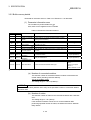
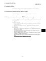
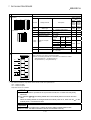
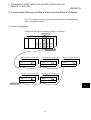
2.2.4 About Ver. 1.10
The module of which the station to station cable length is uniformly 20cm or more by
improving the conventional limit of the station to station cable length is defined as
Ver.1.10.
The conventional modules are defined as Ver.1.00.
Refer to Section 3.2.2 for the maximum overall cable distance of Ver. 1.10.
The conditions for setting the station to station cable length uniformly to 20cm or more
are indicated below.
1) All modules configuring the CC-Link system must use
Version 1.10.
2) All data link cables must be Version 1.10 compatible CCLink dedicated cable.
POINT
In a system where the modules and cables of Ver. 1.00 and Ver. 1.10 are used together, the
maximum overall cable distance and station to station cable length are as specified for Ver. 1.00.
Refer to Section 3.2.1 for the maximum overall cable distance and station to station cable
length of Ver. 1.00.
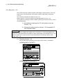
(1) Checking Version 1.10
The "CC-Link" logo is stamped on the "plate" for the Version 1.10 modules.
(a) Rating plate of AJ61BT11
PROGRAMMABLE CONTROLLER
DATE
MADE IN JAPAN
BD992C077H01
(b) Rating plate of A1SJ61BT11
MODEL
POWER
DATE
MADE IN JAPAN
BD992C077H01
2-7
2 SYSTEM CONFIGURATION
MELSEC-A
MEMO
2-8
3 SPECIFICATION
MELSEC-A
3. Specification
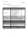
3.1 General Specification
The general specification is shown in Table 3.1.
Table 3.1 General specification
Item
Ambient operating
temperature
Ambient storage
temperature
Ambient operating
humidity
Ambient storage humidity
Vibration resistance
Specifications
0 to 55°C
3
-20 to 75°C
10 to 90% RH, Non-condensing
10 to 90% RH, Non-condensing
Frequency
Acceleration
Under intermittent 10 to 57Hz
Conforming to vibration
57 to 150Hz
JIS B 3502,
IEC 61131-2
Under continuous 10 to 57Hz
vibration
57 to 150Hz
Shock resistance
Operating ambience
Operating elevation
Installation location
Over voltage category 1
Pollution level 2
–
9.8m/s2
–
4.9m/s2
Amplitude
0.075mm
(0.003inch)
No. of sweeps
10 times each in
X, Y, Z
directions
0.035mm
(for 80 min.)
(0.001inch)
–
–
Conforming to JIS B 3502, IEC 61131-2
(147m/s2, 3 times in each of 3 directions X Y Z)
No corrosive gases
2000m (6562 feet) max.
Control panel
II max.
2 max.
1: This indicates the section of the power supply to which the equipment is assumed to be connected between the public
electrical power distribution network and the machinery within the premises. Category II applies to equipment for which
electrical power is supplied from fixed facilities. The surge voltage withstand level for up to the rated voltage of 300V is
2500V.
2: This index indicates the degree to which conductive material is generated in terms of the environment in which the
equipment is used. Pollution level 2 is when only non-conductive pollution occurs. A temporary conductivity caused by
condensation must be expected occasionally.
3-1
3 SPECIFICATION
MELSEC-A
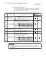
3.2 Performance Specifications
The performance specifications of the CC-Link is shown in Table 3.2.
Table 3.2 Performance specifications
Item
AJ61BT11
Transmission speed
Maximum overall cable distance
(Maximum transmission distance)
A1SJ61BT11
Can select from 156 kbps/ 625 kbps/ 2.5 Mbps/ 5 Mbps/ 10 Mbps
Different from the transmission speed: (Refer to Section 3.2.1, 3.2.2)
Maximum number of connected stations
(when master station)
Number of occupied stations
(when local station)
64 units
However, the following conditions must be satisfied:
{(1×a) + (2×b) + (3×c) + (4×d)} 64
a: number of modules occupying 1 station
b: number of modules occupying 2 stations
c: number of modules occupying 3 stations
d: number of modules occupying 4 stations
{(16×A) + (54×B) + (88×C)} 2304
A: Number of remote I/O stations 64
B: Number of remote device stations 42
C: Number of local stations,
standby master stations,
intelligent device stations 26
1 to 4 stations 1 (switched using DIP switch)
Maximum link points for one system
Link points for one remote/local station
Communication method
Synchronous method
Encoding method
Transmission path
Transmission format
Remote I/O (RX, RY) : 2048 points
Remote register (RWw) : 256 points (master station
remote/local station)
Remote register (RWr) : 256 points (remote/local station
master station)
Remote I/O (RX, RY) : 32 points (local station: 30 points)
Remote register (RWw) : 4 points (master station
remote/local station)
Remote register (RWr) : 4 points (remote/local station
master station)
Polling
Frame sychronous method
NRZI method
Bus (RS-485)
HDLC standard
16
Error control system
12
5
CRC (X + X + X + 1)
CC-Link dedicated cable/CC-Link dedicated high performance cable/Version 1.10
compatible CC-Link dedicated cable 2
Connection cable
Automatic return function
Slave station cutoff function
Error detection by the link special relay/register
RAS function
2
Number of parameter registration to E PROM
I/O occupied points
Internal current consumption (5VDC)
Weight
10,000 times
32 points (I/O allocation: 32 special points)
0.45 A
0.4 kg
0.4 A
0.25 kg
1 : The AJ61BT11 of hardware version F or later and the A1SJ61BT11 of hardware version G or later are compatible with this setting. For
other than the above, the setting is 1 or 4 stations only.
2 : CC-Link dedicated cables cannot be used together with CC-Link dedicated advanced cables.
3-2
3 SPECIFICATION
MELSEC-A
3.2.1 Maximum overall cable distance (for Ver. 1.00)
The relationship between the transmission speed and the maximum overall cable
distance is described below:
(1) For a system consisting of only remote I/O stations and remote
device stations
Remote I/O station
or remote
device station
Remote I/O station
or remote
device station
Master station
2
Remote I/O station
or remote
device station
1
2
Remote I/O station
or remote
device station
1
Maximum overall cable distance
1 Cable length between remote I/O stations or remote device stations.
2 Cable length between the master station and the adjacent stations.
CC-Link dedicated cable (uses terminal resistor 110 Ω)
Transmission rate
156 kbps
625 kbps
2.5 Mbps
Station-to-station cable length
1
2
1200 m (3937.2 ft.)
600 m (1968.6 ft.)
200 m (656.2 ft.)
30 cm (11.81 in.) or more
30 cm (11.81 in.) to
59 cm (23.23 in.)
60 cm (23.62 in.) or more
30 cm (11.81 in.) to
59 cm (23.23 in.)
60 cm (23.62 in.) to
99 cm (38.98 in.)
1 m (3.28 ft.) or more
5 Mbps
10 Mbps
Maximum overall cable distance
110 m (360.9 ft.)
1 m (3.28 ft.) or more
150 m (492.15 ft.)
50 m (164.1 ft.)
80 m (262.5 ft.)
100 m (328.1 ft.)
CC-Link dedicated high performance cable (uses terminal resistor 130 Ω)
Transmission rate
156 kbps
625 kbps
2.5 Mbps
5 Mbps
Number of connected
stations: 1 to 32
Number of connected
stations: 33 to 48
10 Mbps
Number of connected
stations: 49 to 64
Station-to-station cable length
1
2
Maximum overall cable distance
1200 m (3937.2 ft.)
900 m (2952.9 ft.)
400 m (1312.4 ft.)
160 m (524.96 ft.)
30 cm (11.81 in.) or more
100 m (328.1 ft.)
30 cm (11.81 in.) to
39 cm (15.35 in.)
40 cm (15.75 in.) or more
30 cm (11.81 in.) to
39 cm (15.35 in.)
40 cm (15.75 in.) to
69 cm (27.17 in.)
70 cm (27.56 in.) or more
1 m (3.28 ft.) or more
80 m (262.5 ft.)
100 m (328.1 ft.)
20 m (65.52 ft.)
30 m (98.43 ft.)
100 m (328.1 ft.)
The cable length between remote I/O stations or remote device stations is within this range and if even one location is wired, the
maximum overall cable distance will be as indicated above.
3-3
3 SPECIFICATION
MELSEC-A
(Example) When the transmission rate is 10 Mbps, and 43 remote I/O stations and
remote device stations are connected using the CC-Link dedicated high
performance cable, because the cable connecting the second and third
stations is "35 cm (13.78 in.)", the maximum overall cable distance will be
"80 cm (31.5 in.)".
Master station
First
Second
Third
4th
43th
Remote I/O station
Remote device
station
Remote I/O station
Remote I/O station
Remote device
station
1 m (3.28 ft.)
50 cm (19.69 in.)
35 cm (13.78 in.)
50 cm (19.69 in.)
(2) For a system consisting of remote I/O stations, remote device
stations, local stations and intelligent device stations
2
Local station
or intelligent
device station
Remote I/O station
or remote
device station
Remote I/O station
or remote
device station
Master station
1
2
Local station
or intelligent
device station
2
Maximum overall cable distance
1 Cable length between remote I/O stations or remote device stations
2 Cable length between the master station or the local or intelligent device station
and the adjacent stations
CC-Link dedicated cable (uses terminal resistor 110 Ω)
Transmission rate
156 kbps
625 kbps
2.5 Mbps
Station-to-station cable length
1
2
1200 m (3937.2 ft.)
600 m (1968.6 ft.)
200 m (656.2 ft.)
30 cm (11.81 in.) or more
30 cm (11.81 in.) to
59 cm (23.23 in.)
60 cm (23.62 in.) or more
30 cm (11.81 in.) to
59 cm (23.23 in.)
60 cm (23.62 in.) to
99 cm (38.98 in.)
1 m (3.28 ft.) or more
5 Mbps
10 Mbps
Maximum overall cable distance
110 m (360.9 ft.)
2 m (6.56 ft.) or more
150 m (492.15 ft.)
50 m (164.1 ft.)
80 m (262.5 ft.)
100 m (328.1 ft.)
CC-Link dedicated high performance cable (uses terminal resistor 130 Ω)
Transmission rate
156 kbps
625 kbps
2.5 Mbps
5 Mbps
10 Mbps
Station-to-station cable length
1
2
Maximum overall cable distance
1200 m (3937.2 ft.)
600 m (1968.6 ft.)
200 m (656.2 ft.)
30 cm (11.81 in.) or more
30 cm (11.81 in.) to
59 cm (23.23 in.)
60 cm (23.62 in.) or more
70 cm (27.56 in.) to
99 cm (38.98 in.)
1 m (3.28 ft.) or more
2 m (6.56 ft.) or more
110 m (360.9 ft.)
150 m (492.15 ft.)
50 m (164.1 ft.)
80 m (262.5 ft.)
The cable length between remote I/O stations or remote device stations is within this range and if even one location is wired, the
maximum overall cable distance will be as indicated above.
3-4
3 SPECIFICATION
MELSEC-A
3.2.2 Maximum overall cable distance (for Ver. 1.10)
The relation of the transmission speed and maximum overall cable distance when
configuring the entire system with Version 1.10 modules and cable is shown below.
Master station
Remote I/O station
or remote
device station
Remote I/O station
or remote
device station
Local station or
intelligent device
station
Local station or
intelligent device
station
Station to station
cable length
Maximum overall cable distance
Version 1.10 compatible CC-Link dedicated cable (terminal resistor of 110Ω used)
Transmission speed
Station to station cable length
Maximum overall cable distance
156kbps
1200m
625kbps
900m
2.5Mbps
20cm or longer
400m
5Mbps
160m
10Mbps
100m
3-5
3 SPECIFICATION
MELSEC-A
3.3 CC-Link Dedicated Cable
Use the CC-Link dedicated cable for the CC-Link system. If a cable other than the CCLink dedicated cable is used, the performance of the CC-Link system cannot be
guaranteed.
For the specifications and contacts of the CC-Link dedicated cable, visit the CC-Link
Partner Association home page at http://www.cc-link.org/.
3-6
3 SPECIFICATION
MELSEC-A
3.4 I/O Signals to the PC CPU
The I/O signals for the master/local module's PC CPU is described.
3.4.1 I/O signal list
The list of I/O signals is described in Table 3.3.
The "n" in the table indicates the master/local module's first I/O number, and it is
determined by the installation position and the module installed before the master/local
module.
<Example> When the master/local module's first I/O number is "X/Y30":
Xn0 to X(n+1)F X30 to X4F
Yn0 to Y(n+1)F Y30 to Y4F
Table 3.3 I/O signal list
Signal direction: PC CPU
Input
number
Xn0
Xn1
Xn2
Xn3
Xn4
Xn5
Xn6
Xn7
Xn8
Xn9
XnA
XnB
XnC
XnD
Signal name
master/local module
Availability
Master
Local
station station
Module error
Data link status at host station
Parameter setting status
Data link status at other stations
Module reset acceptance complete
(Prohibited to use)
Data link startup by buffer memory
parameter normal completion
Data link startup by buffer memory
parameter error completion
2
Data link startup by E PROM
parameter normal completion
2
Data link startup by E PROM
parameter error completion
2
Parameter registration to E PROM
normal completion
2
Parameter registration to E PROM
error completion
(Prohibited to use)
2
E PROM erasure normal completion
–
Signal direction: PC CPU
Output
number
Yn0
Yn1
Yn2
Yn3
Yn4
Yn5
–
Yn6
Signal name
Refresh command
(Prohibited to use)
Module reset request
(Prohibited to use)
Data link startup request from buffer
memory parameters
Yn7
Yn8
(Prohibited to use)
(Prohibited to use)
–
–
–
–
–
–
–
–
–
–
–
–
Parameter registration request to
2
E PROM
YnB
–
–
Data link startup request from the
2
E PROM parameters
Yn9
YnA
master/local module
Availability
Master
Local
station station
(Prohibited to use)
YnC
YnD
2
E PROM erasure request
2
XnE
XnF
E PROM erasure abnormal
completion
Module ready
YnE
(Prohibited to use)
YnF
: Usable
3-7
: Prohibited to use
3 SPECIFICATION
MELSEC-A
Table 3.3 I/O signal list
Signal direction: PC CPU
Input
number
X(n+1)0
X(n+1)1
X(n+1)2
X(n+1)3
X(n+1)4
X(n+1)5
X(n+1)6
X(n+1)7
X(n+1)8
X(n+1)9
X(n+1)A
X(n+1)B
X(n+1)C
X(n+1)D
X(n+1)E
X(n+1)F
Signal name
master/local module
Availability
Master
Local
station station
(Prohibited to use)
–
–
Signal direction: PC CPU
Output
number
Signal name
master/local module
Availability
Master
Local
station station
Y(n+1)0
Y(n+1)1
Y(n+1)2
Y(n+1)3
Y(n+1)4
Y(n+1)5
(Prohibited to use)
Y(n+1)6
Y(n+1)7
Y(n+1)8
Y(n+1)9
Y(n+1)A
Y(n+1)B
Y(n+1)C Bank switch specification of buffer
Y(n+1)D memory
Y(n+1)E
(Prohibited to use)
Y(n+1)F
: Usable
–
–
–
–
–
: Prohibited to use
Important
The output signals that are prohibited to use as shown in Table 3.3 are used by the system, so
users may not use them. When a user does use (on/off) these signals, a normal operation
cannot be guaranteed.
3-8
3 SPECIFICATION
MELSEC-A
3.4.2 I/O signal details
The on/off timing, conditions, etc. of I/O signals shown in Table 3.3 are described.
(1) Module error: Xn0
Indicates if the module is normal or not.
Turns ON when a watchdog timer error occurs due to a hardware fault or the like.
If the module is abnormal (Xn0 is ON), do not execute the FROM/TO instruction
for the module.
When making a reset, reset the PLC CPU.
OFF : module normal
ON : module error
Module error
(Xn0)
Module ready
(XnF)
(2) Data link status at host station: Xn1
Indicates data link status at the host station.
OFF : data link stopped
ON : data link in progress
Data link status at host station
(Xn1)
Data link startup by buffer
memory/E2PROM parameter
normal completion (Xn6/Xn8)
Parameter setting status
(Xn2)
OFF
Start processing
Host parameter status
(SW0068)
Data link startup request from
buffer memory/E2PROM
Parameter (Yn6/Yn8)
0
Power ON
Module ready
(XnF)
Module error
(Xn0)
OFF
Module reset acceptance
complete (Xn4)
Initialization
Module reset request
(Yn4)
3-9
3 SPECIFICATION
MELSEC-A
(3) Parameter setting status: Xn2
Indicates parameter setting status at host station.
SB006D has the same meaning.
OFF : normal
ON : error in setting (An error code is stored in SW0068.)
Turns off when Yn6 or Yn8 is executed in the status that error does not
occur.
(4) Data link status at other stations: Xn3
Indicates data link status at other stations (remote/local stations).
SB0080 has the same meaning.
OFF : all stations normal
ON : error station exists (An error station status is stored in SW0080 to 83.)
(5) Module reset acceptance complete: Xn4
Indicates the acceptance status of reset request by the module reset request (Yn4).
Reset cannot be performed when module error (Xn0 on).
(a) When module reset request (Yn4) is turned on, module ready (XnF) turns off
and initialization is executed.
When the initialization is completed normally, module ready (XnF) turns on.
Module reset request (Yn4) is turned off by turning on the module reset
acceptance complete (Xn4).
To make a data link, set the data link startup request (Yn6/Yn8) again.
(Normal startup after reset)
Module reset acceptance
complete(Xn4)
Initialization
Module ready(XnF)
Module reset request
(Yn4)
(b) When module reset request (Yn4) is turned on, module ready (XnF) turns off
and initialization is executed.
When the initialization is completed abnormally, module ready (XnF) does not
turn on, but module error (Xn0) turns on.
(Error startup after reset)
Module reset acceptance OFF
complete (Xn4)
Initialization
Module ready (XnF)
Module error (Xn0)
Module reset request
(Yn4)
3 - 10
3 SPECIFICATION
MELSEC-A
(6) Data link startup by buffer memory parameter normal completion: Xn6
Indicates normal completion in data link startup requested by the buffer-memory
parameter data link startup request (Yn6).
(a) When (Yn6) is turned on, the parameter contents at the (address 0H to 5FH) in
buffer memory are checked. If the check result is normal data link is started
automatically.
(b) When data link is normally started, the signal for "data link startup by buffermemory parameter normal completion" (Xn6) is turned on.
(c) (Xn6) is turned off by turning off (Yn6).
Data link startup by buffer-memory
parameter normal completion (Xn6)
Parameter setting status (Xn2)
OFF
Start processing
Host station parameter status
(SW0068)
0
Buffer-memory parameter
data link startup request (Yn6)
(7) Data link startup by buffer memory parameter error completion: Xn7
Indicates abnormal completion in data link startup requested by the buffermemory parameter data link startup request (Yn6).
(a) When (Yn6) is turned on, the parameter contents at the (address 0H to 5FH) in
buffer memory are checked. If error is detected the signal for "data link startup
by buffer-memory parameter abnormal completion" (Xn7) is turned on.
(b) Parameter setting status (Xn2) is turned on and the error code is stored in the
host station parameter status in buffer memory (SW0068).
(c) (Xn7) is turned off by turning off (Yn6).
Data link startup by buffer-memory
parameter error completion (Xn7)
Parameter setting status (Xn2)
OFF
Start
processing
Host station parameter status
(SW0068)
Buffer-memory parameter
data link startup request (Yn6)
3 - 11
0
Error code
3 SPECIFICATION
MELSEC-A
(8) Data link startup by E2PROM parameter normal completion: Xn8
Indicates normal completion in data link startup requested by the E2PROM
parameter data link startup request (Yn8).
(a) When (Yn8) is turned on, the E2PROM parameter contents are checked. If
the check result is normal data link is started automatically.
(b) When data link is normally started, the signal for "data link startup by
E2PROM parameter normal completion" (Xn8) is turned on.
(c) (Xn8) is turned off by turning off (Yn8).
2
Data link startup by E PROM
parameter normal completion (Xn8)
Parameter setting status (Xn2)
OFF
Start
processing
Host station parameter status
(SW0068)
0
2
E PROM parameter data link
startup request (Yn8)
(9) Data link startup by E2PROM parameter error completion: Xn9
Indicates abnormal completion in data link startup requested by the E2PROM
parameter data link startup request (Yn8).
(a) When (Yn8) is turned on, the E2PROM parameter contents are checked. If
error is detected the signal for "data link startup by E2PROM parameter
abnormal completion" (Xn9) is turned on.
(b) Parameter setting status (Xn2) is turned on and the error code is stored in the
host station parameter status in buffer memory (SW0068).
(c) (Xn9) is turned off by turning off (Yn8).
2
Data link startup by E PROM
parameter error completion (Xn9)
Parameter setting status (Xn2)
Start
processing
Host station parameter status
(SW0068)
2
E PROM parameter data link
startup request (Yn8)
3 - 12
0
Error code
3 SPECIFICATION
MELSEC-A
(10) Parameter registration to E2PROM normal completion: XnA
Indicates normal completion in registering parameters at (buffer-memory address
0H to 5FH) to E2PROM requested by the parameter registration request to
E2PROM (YnA).
(a) When (YnA) is turned on, the parameter contents stored in the parameter
information area buffer memory (address 0H to 5FH) are checked. If the
parameters are registered to E2PROM.
(b) When registration is normally completed, the signal for "parameter registration
to E2PROM normal completion" (XnA) is turned on.
(c) (XnA) is turned off by turning off (YnA).
2
Parameter registration to E PROM
normal completion (XnA)
Registor
processing
2
Registration to E PROM status
(SW00B9)
0
Parameter registration request to
2
E PROM (YnA)
(11) Parameter registration to E2PROM error completion: XnB
Indicates abnormal completion in registering parameters at (buffer-memory
address 0H to 5FH) to E2PROM requested by the parameter registration request
to E2PROM (YnA).
(a) When the parameter registration request (YnA) to the E2PROM is turned on,
the parameters stored in the buffer-memory "parameter information area
(address 0H to 5FH)" are written to the E2PROM.
(b) When the registration ends error, the E2PROM parameter registration error
(XnB) turns on and the error code is stored in the buffer memory E2PROM
registration status (SW00B9).
(c) (XnB) is turned off by turning off (YnA).
2
Parameter registration to E PROM
error completion (XnB)
Registor
processing
Registration to E2 PROM status
(SW00B9)
Parameter registration request to
2
E PROM (YnA)
3 - 13
0
Error code
3 SPECIFICATION
MELSEC-A
(12) E2PROM erasure normal completion: XnD
This signal indicates the normal completion of erasing the parameters in the
E2PROM in response to the E2PROM erasure request (YnD).
(a) When the E2PROM erasure request (YnD) turns on, the parameters in the
E2PROM are erased.
(b) On normal completion of erasure, the E2PROM erasure normal completion
(XnD) turns on.
(c) By turning off the E2PROM erasure request (YnD), the E2PROM erasure
normal completion (XnD) turns off.
2
E2PROM erasure normal completion
(XnD)
Erasure
processing
E2PROM erasure result
(SW00BA)
0
E2PROM erasure request
(YnD)
3 - 14
3 SPECIFICATION
MELSEC-A
(13) E2PROM erasure abnormal completion: XnE
This signal indicates the abnormal completion of erasing the parameters in the
E2PROM in response to the E2PROM erasure request (YnD).
(a) When the E2PROM erasure request (YnD) turns on, the parameters in the
E2PROM are erased.
(b) On abnormal completion of erasure, the E2PROM erasure abnormal
completion (XnE) turns on and the error code is stored into the E2PROM
erasure result (SW00BA) of the buffer memory.
(c) By turning off the E2PROM erasure request (YnD), the E2PROM erasure
abnormal completion (XnE) turns off.
E2PROM erasure abnormal completion
(XnE)
Erasure
processing
E2 PROM erasure result
(SW00BA)
0
2
E2PROM erasure request
(YnD)
3 - 15
Error code
3 SPECIFICATION
MELSEC-A
(14) Module ready: XnF
Indicates if the module is ready for operation.
Used as an interlock signal when a sequence program is used to make access to
the master/local module.
(a) Turns on automatically when the module becomes ready for operation.
(b) Turns off when one of the following conditions occur:
There is an error in the module switch settings.
The module reset request signal (Yn4) is turned on.
The module error signal (Xn0) is turned on.
If the module is inoperative (XnF is OFF), do not execute the FROM/TO
instruction for the module.
Power supply ON
Module ready
(XnF)
Module error
(Xn0)
Module reset request
(Yn4)
(15) Refresh command: Yn0
Indicates if the content of remote output RY (address 160H to 1DFH) in the buffer
memory is effective or not. Same meaning for local stations.
For remote input RX and remote register RWr/RWw except remote output RY,
refresh is continued independently of this signal.
OFF : Not effective (Sends all-off data.)
ON : Effective (Sends data in "remote output (address 160H to 1DFH)" in the
buffer memory.)
Master station
Remote I/O station
Remote device station
Remote input (RX)
Local station
Remote output (RY)
Input
Remote input (RX)
Remote output (RY)
Remote input (RX)
Output
Remote output (RY)
POINT
(1) Yn0 is set (on) before the data link start up.
(2) Yn0 is turned off when the PC CPU is in the STOP status.
3 - 16
3 SPECIFICATION
MELSEC-A
(16) Module reset request: Yn4
Signal used to reset the module for debugging.
The module can be reset individually without resetting the PC CPU.
If you cannot start the remote station earlier than starting the system in any
method, resetting the module after the start of the remote station allows the
system to start from the initial status securely.
While the module reset request is being executed (Yn4 is ON), do not execute
the FROM/TO instruction for the module.
Refer to (5) for signal timing.
(17) Data link startup request from buffer memory parameter: Yn6
Starts data link according to the parameter (address 0H to 5FH) contents in buffer
memory.
Do not turn on this signal during RUN of the PLC CPU and during a data link.
If you are going to change any parameter data during RUN of the PLC CPU and
during a data link, always turn on SB0002 (data link stop) to stop the data link,
change the parameter data, and then turn on this signal to restart the data link.
Refer to (6) and (7) for signal timing.
(18) Data link startup request from E2PROM parameter: Yn8
Starts data link according to the parameter contents registered in E2PROM.
Do not turn on this signal during RUN of the PLC CPU and during a data link.
If you are going to change any parameter data during RUN of the PLC CPU and
during a data link, always turn on SB0002 (data link stop) to stop the data link,
change the parameter data, and then turn on this signal to restart the data link.
Refer to (8) and (9) for signal timing.
POINT
2
The factory-set E PROM values are indefinite. Before making a data link startup using the Yn8
signal, always execute parameter registration using the YnA signal at least once.
(19) Parameter registration request to E2PROM: YnA
The signal for registering parameter (address 0H to 5FH) in buffer memory to
E2PROM.
2
Since the number of times parameters are registered to E PROM is limited to
10,000, execute parameter registration using the YnA signal by the minimum
number of times required.
Refer to (10) and (11) for signal timing.
(20) E2PROM erasure request: YnD
The signal for erasing the parameters in the E2PROM.
Refer to (12) and (13) for the signal timing.
(21) Bank switch specification of buffer memory : Y(n+1) C, Y(n+1)D
Specifies bank switch of buffer memory.
Y(n+1)C
OFF
Y(n+1)D
OFF
Buffer memory
Specify 0 bank
ON
OFF
Specify 1 bank
OFF
ON
Specify 2 bank
ON
ON
–
3 - 17
Application
Parameter, status information, etc.
Intelligent device station
Send/recieve buffer
Intelligent device station
Automatic update buffer
Prohibited to use
3 SPECIFICATION
MELSEC-A
3.5 Buffer Memory
The buffer memory is used to swap data between the master/local module and the PC
CPU.
In the PC CPU, the FROM/TO instructions are used to read/write data.
The contents of the buffer memory return to the default values when the power is
turned off and the PC CPU is reset.
3.5.1 Buffer memory list
The buffer memory list is shown in Table 3.4.
Table 3.4 (1) Buffer memory list (bank 0)
Address
Hex.
Dec.
0H to 5FH
0 to 95
60H to 7FH
96 to 127
80H to CDH
128 to 205
CEH to DFH
206 to 223
E0H to 15FH
224 to 351
160H to 1DFH
1E0H to 2DFH
2E0H to 3DFH
352 to 479
480 to 735
736 to 991
3E0H to 5DFH 992 to 1503
Item
Details
Parameter information
area
(Prohibited to use)
Parameter information
area
(Prohibited to use)
Stores the information (parameters) to
execute the data link.
–
Stores the information (parameters) to
execute the data link.
–
When master station: Stores the input
status from the remote/local station.
Remote input (RX)
When local station: stores the input status
from the master station.
When master station: Stores the output
status of the output to the remote/local
station.
Remote output (RY)
When local station: Stores the output status
of the output to the master station.
When master station: Stores the
Remote register (RWw) transmission data to the remote/all local
stations.
(Master station: for
sending
When local station: Stores the transmission
Local station: for
data to the master/other local stations.
sending/receiving)
Also, stores the received data from the
remote/other local stations.
Remote register (RWr)
(Master station: for
receiving
Local station: for
receiving)
800H to 9FFH 2048 to 2559
(Prohibited to use)
A00H to FFFH
–
–
–
–
Section
3.5.2 (1)
–
Section
15.2.1
–
–
Read only
Write only
–
Read/write
enabled
Section
3.5.2 (2)
–
Write only
–
Read/write
enabled
–
Section
3.5.2 (3)
–
Write only
When local station: Stores the received
data from the master station.
–
5E0H to 5FFH 1504 to 1535 Link special relay (SB) Stores the data-link status.
Link special register
(SW)
Read/write
enabled
–
Read/write
enabled
–
When master station: Stores the received
data from the remote/local station.
(Prohibited to use)
600H to 7FFH 1536 to 2047
Availability
Read/write
Master Local Reference
possibility
station station
Stores the data-link status.
–
Uses for dedicated instruction of RIRD,
2560 to 4095 Random access buffer
RIWT, etc.
–
–
–
Read/write
enabled
(write
disabled
depending
on the
device)
–
Read/write
enabled
3 - 18
–
Section
3.5.2 (4)
Section
3.5.2 (5)
–
: Usable
Do not write to areas that are prohibited to use. An error may occur.
–
–
–
Section
15.6
: Prohibited to use
3 SPECIFICATION
MELSEC-A
Table 3.4 (2) Buffer memory list (bank 1)
Address
Hex.
Dec.
0H to FFFH
0 to 4095
Item
Communication buffer
Details
Availability
Read/write
Master Local Reference
possibility
station station
When the transient transmission
(communication using communication
buffer) is performed with the intelligent
Read/write
device stations, this stores the
enabled
communication data and control data.
The area for each intelligent device station
is set with the network parameters.
Section
15.2.1
Table 3.4 (3) Buffer memory list (bank 2)
Address
Hex.
0H to FFFH
Dec.
0 to 4095
Item
Automatic updating
buffer
Details
Availability
Read/write
Master Local Reference
possibility
station station
When the transient transmission
(communication using automatic updating
buffer) is performed with the intelligent
Read/write
device stations, this stores the automatic
enabled
updating data.
The area for each intelligent device station
is set with the network parameters.
3 - 19
Section
15.2.1
3 SPECIFICATION
MELSEC-A
3.5.2 Buffer memory details
The details of each item shown in Table 3.4 of Section 3.5.1 is described.
(1) Parameter information area
The conditions to perform data link is set.
Also, these can be registered in the E2PROM.
Table 3.5 Parameter information area list
Address
Hex.
Dec.
0H
1H
2H
3H
4H
5H
6H
7H to FH
10H to 13H
14H to 17H
18H to 1FH
Item
0
Description
(Prohibited to use)
Number of connected
1
modules
2
Number of retries
Number of automatic
3
return modules
4
(Prohibited to use)
5
(Prohibited to use)
Operation specification
6
when CPU is down
7 to 15
(Prohibited to use)
Reserved station
16 to 19
specification
Invalid station
20 to 23
specification
24 to 31
(Prohibited to use)
20H to 5FH 32 to 95 Station information
–
Set the number of connected remote/local station modules.
(including reserved stations)
Set the number of retries to the communication faulty station.
Set the number of remote/local stations modules that can
return with 1 link scan.
–
–
Specify the data-link status when there is a master station PC
CPU error.
–
Default
–
64
3
1
–
–
0 (Stop)
–
Set a reserved station.
0 (No specification)
Specify an invalid station.
0 (No specification)
–
Set the connected remote/local station type.
–
Station type: Remote I/O
station
Number of occupied
stations: 1
Station numbers: 1 to 64
Do not write to areas that are prohibited to use. An error may occur.
(a) Number of connected modules
This sets the number of remote/local station modules connected to the
master station (including reserved stations).
This is not a station count.
The setting range is "1 to 64 (modules)."
POINT
The station information (address 20H to 5FH) for the specified "number of connected" stations
becomes valid.
(b) Number of retries
This sets the number of retries to the remote/local station with a data link
error.
The setting range is "1 to 7(times)."
If the remote/local station cannot recover a normal data link after
performing specified number of retries, the station becomes a "data-link
faulty station."
3 - 20
3 SPECIFICATION
MELSEC-A
(c) Number of automatic return modules
This sets the number of remote/local stations that can return to the system
during 1 link scan.
The range is "1 to 10 (modules)."
(d) Operation specification when CPU is down
This specifies the data-link status when the master station PC CPU has an
error which "stops the error operation".
"0" is stop and "1" is continue.
(e) Reserved station specification
This is set to include the remote/local stations that are not actually
connected in the number of connected modules, so that a data link error
does not occur.
1 When a connected remote/local station is set as a reserved station, the
station cannot perform any data link at all.
2 Turn on the bit corresponding to the station number to be set as
reserved.
However, for the remote/local station that occupies more than 2 stations,
turn on the only bit for the station numbers set by the module's station
number setting switch.
1 to 64 in the table below indicate the station numbers.
Address
10H
11H
12H
13H
b15
b14
b13
b12
b11
b10
b9
b8
b7
b6
b5
b4
b3
b2
b1
b0
16
32
48
64
15
31
47
63
14
30
46
62
13
29
45
61
12
28
44
60
11
27
43
59
10
26
42
58
9
25
41
57
8
24
40
56
7
23
39
55
6
22
38
54
5
21
37
53
4
20
36
52
3
19
35
51
2
18
34
50
1
17
33
49
<Setting example>
When setting a local station with station number 4 and a remote station
with station number 9 as reserved in the system configuration below:
Stations to be connected in the future
Station No.4
Master
station
Station No.1
Local station
(occupies 4
stations)
Station No.3
Remote station
Remote station
(occupies 2 stations) (occupies 1 station)
Address
10H
11H
12H
13H
Station No.8
Station No.9
Remote station
(occupies 1 station)
Remote station
(occupies 1 station)
b15
b14
b13
b12
b11
b10
b9
b8
b7
b6
b5
b4
b3
b2
b1
b0
0
0
0
0
0
0
0
0
0
0
0
0
0
0
0
0
0
0
0
0
0
0
0
0
0
0
0
0
1
0
0
0
0
0
0
0
0
0
0
0
0
0
0
0
0
0
0
0
1
0
0
0
0
0
0
0
0
0
0
0
0
0
0
0
3 - 21
3 SPECIFICATION
MELSEC-A
(f) Error invalid station specification
This is set so that the remote/local station that can no longer perform data
link due to power off, etc. will not be treated as a "data-link faulty station" on
the master station and the local station.
Be careful, however, for errors will not be detected.
1 When the same station number is specified as a reserved station, the
reserved station specification has the priority.
2 Turn on the bit corresponding to the station number of the invalid station.
However, for remote/local stations that occupy more than 2 stations, turn
on the only bit for the station numbers set by the module's station
number setting switch.
1 to 64 in the table below indicate the station numbers.
Address
14H
15H
16H
17H
b15
b14
b13
b12
b11
b10
b9
b8
b7
b6
b5
b4
b3
b2
b1
b0
16
32
48
64
15
31
47
63
14
30
46
62
13
29
45
61
12
28
44
60
11
27
43
59
10
26
42
58
9
25
41
57
8
24
40
56
7
23
39
55
6
22
38
54
5
21
37
53
4
20
36
52
3
19
35
51
2
18
34
50
1
17
33
49
<Setting example>
When setting a local station with station number 4 and a remote station
with station number 9 as invalid in the system configuration below:
Set as invalid stations
Station No.4
Master
station
Station No.1
Local station
(occupies 4
stations)
Station No.3
Remote station
Remote station
(occupies 2 stations) (occupies 1 station)
Address
14H
15H
16H
17H
b15
0
0
0
0
b14
0
0
0
0
b13
0
0
0
0
b12
0
0
0
0
b11
0
0
0
0
b10
0
0
0
0
b9
0
0
0
0
3 - 22
b8
1
0
0
0
b7
0
0
0
0
Station No.8
Station No.9
Remote station
(occupies 1 station)
Remote station
(occupies 1 station)
b6
0
0
0
0
b5
0
0
0
0
b4
0
0
0
0
b3
1
0
0
0
b2
0
0
0
0
b1
0
0
0
0
b0
0
0
0
0
3 SPECIFICATION
MELSEC-A
(g) Station information
This sets the remote/local station type for connected remote/local stations
and reserved stations.
1 The data configuration to be set is shown below.
b15
to
b12
b11
to
b8
b7
to
Number of
occupied stations
Station type
b0
Station number
1 to 64
(01H to 40H)
1: occupies 1 station
2: occupies 2 stations
3: occupies 3 stations
4: occupies 4 stations
0: Remote I/O station
1: Remote device station
2: Intelligent device station (including local station)
2
Module
1st module
2nd module
3rd module
4th module
5th module
6th module
7th module
8th module
9th module
10th module
11th module
12th module
13th module
14th module
15th module
16th module
Address
20H
21H
22H
23H
24H
25H
26H
27H
28H
29H
2AH
2BH
2CH
2DH
2EH
2FH
The buffer memory address for each module is shown in the table
below.
For example, when setting for the 25th module, write to the buffer
memory address "38H."
Module
17th module
18th module
19th module
20th module
21th module
22th module
23th module
24th module
25th module
26th module
27th module
28th module
29th module
30th module
31th module
32th module
Address
30H
31H
32H
33H
34H
35H
36H
37H
38H
39H
3AH
3BH
3CH
3DH
3EH
3FH
Module
33th module
34th module
35th module
36th module
37th module
38th module
39th module
40th module
41th module
42th module
43th module
44th module
45th module
46th module
47th module
48th module
Address
40H
41H
42H
43H
44H
45H
46H
47H
48H
49H
4AH
4BH
4CH
4DH
4EH
4FH
Module
49th module
50th module
51th module
52th module
53th module
54th module
55th module
56th module
57th module
58th module
59th module
60th module
61th module
62th module
63th module
64th module
Address
50H
51H
52H
53H
54H
55H
56H
57H
58H
59H
5AH
5BH
5CH
5DH
5EH
5FH
<Setting example>
When connecting a remote I/O station, a remote device station and a
local station:
<<Station information setting>>
<<System configuration example>>
3rd module
of
Station Number
occupied
type
stations
Local station
1st module
Master
station
Remote I/O
station
2nd module
Remote device
station
Station No.4
(occupies 4
stations)
Station No.1
Station No.2
(occupies 1 station) (occupies 2 stations)
3 - 23
Station number
Address 20H
0H
1H
01H
21H
1H
2H
02H
22H
2H
4H
04H
3 SPECIFICATION
MELSEC-A
(2) Remote input (RX) and remote output (RY)
(a) Master station Remote I/O station/remote device
station/local station
1
Master station
Input status from remote I/O station, remote device station (RX) and
local station (RY) are stored.
Two words are used per station.
Remote I/O station
(station No.1: occupies 1 station)
Master station
Address
For station No.1
For station No.2
For station No.3
For station No.4
For station No.5
For station No.6
For station No.7
For station No.8
For station No.9
E0H
E1H
E2H
E3H
E4H
E5H
E6H
E7H
E8H
E9H
EAH
EBH
ECH
EDH
EEH
EFH
F0H
F1H
F2H
to
15BH
15CH
For station No.63
15DH
15EH
For station No.64
15FH
Remote input (RX)
Remote input (RX)
RX F
RX 1F
RX 2F
RX 3F
RX 4F
RX 5F
RX 6F
RX 7D
RX 8F
RX 9F
RX AF
RX BF
RX CF
RX DF
RX EF
RX FD
RX10F
RX11F
to
to
to
to
to
to
to
to
to
to
to
to
to
to
to
to
to
to
Remote device station
(station No.2: occupies 2 stations)
RX 0
RX 10
RX 20
RX 30
RX 40
RX 50
RX 60
RX 70
RX 80
RX 90
RX A0
RX B0
RX C0
RX D0
RX E0
RX F0
RX100
RX110
X0F to X00
X1F to X10
RX0F to RX00
RX1F to RX10
to
RX7CF
RX7DF
RX7EF
RX7FF
to
to
to
to
RX7C0
RX7D0
RX7E0
RX7F0
Master station's buffer memory and station number correspondence table
Station
number
1
2
3
4
5
6
7
8
9
10
11
12
13
Buffer memory
address
E0H to E1H
E2H to E3H
E4H to E5H
E6H to E7H
E8H to E9H
EAH to EBH
ECH to EDH
EEH to EFH
F0H to F1H
F2H to F3H
F4H to F5H
F6H to F7H
F8H to F9H
Station
number
14
15
16
17
18
19
20
21
22
23
24
25
26
Buffer memory
address
FAH to FBH
FCH to FDH
FEH to FFH
100H to 101H
102H to 103H
104H to 105H
106H to 107H
108H to 109H
10AH to 10BH
10CH to 10DH
10EH to 10FH
110H to 111H
112H to 113H
Station
number
27
28
29
30
31
32
33
34
35
36
37
38
39
Buffer memory
address
114H to 115H
116H to 117H
118H to 119H
11AH to 11BH
11CH to 11DH
11EH to 11FH
120H to 121H
122H to 123H
124H to 125H
126H to 127H
128H to 129H
12AH to 12BH
12CH to 12DH
3 - 24
Station
number
40
41
42
43
44
45
46
47
48
49
50
51
52
Buffer memory
address
12EH to 12FH
130H to 131H
132H to 133H
134H to 135H
136H to 137H
138H to 139H
13AH to 13BH
13CH to 13DH
13EH to 13FH
140H to 141H
142H to 143H
144H to 145H
146H to 147H
Station
number
53
54
55
56
57
58
59
60
61
62
63
64
–
Buffer memory
address
148H to 149H
14AH to 14BH
14CH to 14DH
14EH to 14FH
150H to 151H
152H to 153H
154H to 155H
156H to 157H
158H to 159H
15AH to 15BH
15CH to 15DH
15EH to 15FH
–
3 SPECIFICATION
MELSEC-A
2
Local station
Data to be sent to master station is stored in the remote output (RY)
corresponding to the host station.
Input status from remote I/O station, remote device station (RX) and
other local station are stored.
Two words are used per station.
... The last 2 bits cannot be used when the master station and the
local station are communicating.
Local station
(station No.5: occupies 4 stations)
Local station
(station No.4: occupies 1 station)
Remote output (RY)
RY F
RY 1F
RY 2F
RY 3F
RY 4F
RY 5F
RY 6F
RY 7D
RY 8F
RY 9F
RY AF
RY BF
RY CF
RY DF
RY EF
RY FD
RY10F
RY11F
to
to
to
to
to
to
to
to
to
to
to
to
to
to
to
to
to
to
Remote output (RY)
RY 0
RY 10
RY 20
RY 30
RY 40
RY 50
RY 60
RY 70
RY 80
RY 90
RY A0
RY B0
RY C0
RY D0
RY E0
RY F0
RY100
RY110
RY F
RY 1F
RY 2F
RY 3F
RY 4F
RY 5F
RY 6F
RY 7D
RY 8F
RY 9F
RY AF
RY BF
RY CF
RY DF
RY EF
RY FD
RY10F
RY11F
to
RY7CF
RY7DF
RY7EF
RY7FF
to
to
to
to
to
to
to
to
to
to
to
to
to
to
to
to
to
to
to
to
to
to
RY 0
RY 10
RY 20
RY 30
RY 40
RY 50
RY 60
RY 70
RY 80
RY 90
RY A0
RY B0
RY C0
RY D0
RY E0
RY F0
RY100
RY110
to
RY7C0
RY7D0
RY7E0
RY7F0
RY7CF
RY7DF
RY7EF
RY7FF
to
to
to
to
Address
160H
161H
162H
163H
164H
165H
166H
167H
168H
169H
16AH
16BH
16CH
16DH
16EH
16FH
170H
171H
172H
For station No.1
For station No.2
For station No.3
For station No.4
For station No.5
For station No.6
For station No.7
For station No.8
For station No.9
to
RY7C0
RY7D0
RY7E0
RY7F0
1DBH
1DCH
For station No.63
1DDH
1DEH
For station No.64
1DFH
Local station's buffer memory address and station number correspondence table
Station
number
1
2
3
4
5
6
7
8
9
10
11
12
13
Buffer memory
address
160H to 161H
162H to 163H
164H to 165H
166H to 167H
168H to 169H
16AH to 16BH
16CH to 16DH
16EH to 16FH
170H to 171H
172H to 173H
174H to 175H
176H to 177H
178H to 179H
Station
number
14
15
16
17
18
19
20
21
22
23
24
25
26
Buffer memory
address
17AH to 17BH
17CH to 17DH
17EH to 17FH
180H to 181H
182H to 183H
184H to 185H
186H to 187H
188H to 189H
18AH to 18BH
18CH to 18DH
18EH to 18FH
190H to 191H
192H to 193H
Station
number
27
28
29
30
31
32
33
34
35
36
37
38
39
Buffer memory
address
194H to 195H
196H to 197H
198H to 199H
19AH to 19BH
19CH to 19DH
19EH to 19FH
1A0H to 1A1H
1A2H to 1A3H
1A4H to 1A5H
1A6H to 1A7H
1A8H to 1A9H
1AAH to 1ABH
1ACH to 1ADH
3 - 25
Station
number
40
41
42
43
44
45
46
47
48
49
50
51
52
Buffer memory
address
1AEH to 1AFH
1B0H to 1B1H
1B2H to 1B3H
1B4H to 1B5H
1B6H to 1B7H
1B8H to 1B9H
1BAH to 1BBH
1BCH to 1BDH
1BEH to 1BFH
1C0H to 1C1H
1C2H to 1C3H
1C4H to 1C5H
1C6H to 1C7H
Station
number
53
54
55
56
57
58
59
60
61
62
63
64
–
Buffer memory
address
1C8H to 1C9H
1CAH to 1CBH
1CCH to 1CDH
1CEH to 1CFH
1D0H to 1D1H
1D2H to 1D3H
1D4H to 1D5H
1D6H to 1D7H
1D8H to 1D9H
1DAH to 1DBH
1DCH to 1DDH
1DEH to 1DFH
–
3 SPECIFICATION
MELSEC-A
(b) Master station
station
1
Master station
Output status to remote I/O station, remote device station (RY) and all
local stations (RX) are stored.
Two words are used per station.
Remote I/O station
(station No.1: occupies 1 station)
Master station
Address
For station No.1
For station No.2
For station No.3
For station No.4
For station No.5
For station No.6
For station No.7
For station No.8
For station No.9
160H
161H
162H
163H
164H
165H
166H
167H
168H
169H
16AH
16BH
16CH
16DH
16EH
16FH
170H
171H
172H
RY F
RY 1F
RY 2F
RY 3F
RY 4F
RY 5F
RY 6F
RY 7D
RY 8F
RY 9F
RY AF
RY BF
RY CF
RY DF
RY EF
RY FD
RY10F
RY11F
to
to
to
to
to
to
to
to
to
to
to
to
to
to
to
to
to
to
Remote device station
(station No.2: occupies 2 stations)
Remote output (RY)
Remote output (RY)
to
1DBH
1DCH
For station No.63
1DDH
1DEH
For station No.64
1DFH
remote I/O station/remote device station/local
RY 0
RY 10
RY 20
RY 30
RY 40
RY 50
RY 60
RY 70
RY 80
RY 90
RY A0
RY B0
RY C0
RY D0
RY E0
RY F0
RY100
RY110
Y0F to Y00
Y1F to Y10
RY0F to RY00
RY1F to RY10
to
RY7CF
RY7DF
RY7EF
RY7FF
to
to
to
to
RY7C0
RY7D0
RY7E0
RY7F0
Master station's buffer memory and station number correspondence table
Station
number
1
2
3
4
5
6
7
8
9
10
11
12
13
Buffer memory
address
160H to 161H
162H to 163H
164H to 165H
166H to 167H
168H to 169H
16AH to 16BH
16CH to 16DH
16EH to 16FH
170H to 171H
172H to 173H
174H to 175H
176H to 177H
178H to 179H
Station
number
14
15
16
17
18
19
20
21
22
23
24
25
26
Buffer memory
address
17AH to 17BH
17CH to 17DH
17EH to 17FH
180H to 181H
182H to 183H
184H to 185H
186H to 187H
188H to 189H
18AH to 18BH
18CH to 18DH
18EH to 18FH
190H to 191H
192H to 193H
Station
number
27
28
29
30
31
32
33
34
35
36
37
38
39
Buffer memory
address
194H to 195H
196H to 197H
198H to 199H
19AH to 19BH
19CH to 19DH
19EH to 19FH
1A0H to 1A1H
1A2H to 1A3H
1A4H to 1A5H
1A6H to 1A7H
1A8H to 1A9H
1AAH to 1ABH
1ACH to 1ADH
3 - 26
Station
number
40
41
42
43
44
45
46
47
48
49
50
51
52
Buffer memory
address
1AEH to 1AFH
1B0H to 1B1H
1B2H to 1B3H
1B4H to 1B5H
1B6H to 1B7H
1B8H to 1B9H
1BAH to 1BBH
1BCH to 1BDH
1BEH to 1BFH
1C0H to 1C1H
1C2H to 1C3H
1C4H to 1C5H
1C6H to 1C7H
Station
number
53
54
55
56
57
58
59
60
61
62
63
64
–
Buffer memory
address
1C8H to 1C9H
1CAH to 1CBH
1CCH to 1CDH
1CEH to 1CFH
1D0H to 1D1H
1D2H to 1D3H
1D4H to 1D5H
1D6H to 1D7H
1D8H to 1D9H
1DAH to 1DBH
1DCH to 1DDH
1DEH to 1DFH
–
3 SPECIFICATION
MELSEC-A
2
Local station
Data received from remote I/O station, remote device station (RY) and
master station (RY) are stored.
Two words are used per station.
... The last 2 bits cannot be used when the master station and the
local station are communicating.
Local station
(station No.4: occupies 1 station)
Local station
(station No.5: occupies 4 stations)
Remote input (RX)
Remote input (RX)
Address
RX F
RX 1F
RX 2F
RX 3F
RX 4F
RX 5F
RX 6F
RX 7D
RX 8F
RX 9F
RX AF
RX BF
RX CF
RX DF
RX EF
RX FD
RX10F
RX11F
RX F
RX 1F
RX 2F
RX 3F
RX 4F
RX 5F
RX 6F
RX 7D
RX 8F
RX 9F
RX AF
RX BF
RX CF
RX DF
RX EF
RX FD
RX10F
RX11F
E0H
E1H
E2H
E3H
E4H
E5H
E6H
E7H
E8H
E9H
EAH
EBH
ECH
EDH
EEH
EFH
F0H
F1H
F2H
to
to
to
to
to
to
to
to
to
to
to
to
to
to
to
to
to
to
RX 0
RX 10
RX 20
RX 30
RX 40
RX 50
RX 60
RX 70
RX 80
RX 90
RX A0
RX B0
RX C0
RX D0
RX E0
RX F0
RX100
RX110
to
to
to
to
RX 0
RX 10
RX 20
RX 30
RX 40
RX 50
RX 60
RX 70
RX 80
RX 90
RX A0
RX B0
RX C0
RX D0
RX E0
RX F0
RX100
RX110
to
to
RX7CF
RX7DF
RX7EF
RX7FF
to
to
to
to
to
to
to
to
to
to
to
to
to
to
to
to
to
to
RX7C0
RX7D0
RX7E0
RX7F0
RX7CF
RX7DF
RX7EF
RX7FF
to
to
to
to
For station No.1
For station No.2
For station No.3
For station No.4
For station No.5
For station No.6
For station No.7
For station No.8
For station No.9
to
RX7C0
RX7D0
RX7E0
RX7F0
15BH
15CH
For station No.63
15DH
15EH
For station No.64
15FH
Local station's buffer memory address and station number correspondence table
Station
number
1
2
3
4
5
6
7
8
9
10
11
12
13
Buffer memory
address
E0H to E1H
E2H to E3H
E4H to E5H
E6H to E7H
E8H to E9H
EAH to EBH
ECH to EDH
EEH to EFH
F0H to F1H
F2H to F3H
F4H to F5H
F6H to F7H
F8H to F9H
Station
number
14
15
16
17
18
19
20
21
22
23
24
25
26
Buffer memory
address
FAH to FBH
FCH to FDH
FEH to FFH
100H to 101H
102H to 103H
104H to 105H
106H to 107H
108H to 109H
10AH to 10BH
10CH to 10DH
10EH to 10FH
110H to 111H
112H to 113H
Station
number
27
28
29
30
31
32
33
34
35
36
37
38
39
Buffer memory
address
114H to 115H
116H to 117H
118H to 119H
11AH to 11BH
11CH to 11DH
11EH to 11FH
120H to 121H
122H to 123H
124H to 125H
126H to 127H
128H to 129H
12AH to 12BH
12CH to 12DH
3 - 27
Station
number
40
41
42
43
44
45
46
47
48
49
50
51
52
Buffer memory
address
12EH to 12FH
130H to 131H
132H to 133H
134H to 135H
136H to 137H
138H to 139H
13AH to 13BH
13CH to 13DH
13EH to 13FH
140H to 141H
142H to 143H
144H to 145H
146H to 147H
Station
number
53
54
55
56
57
58
59
60
61
62
63
64
–
Buffer memory
address
148H to 149H
14AH to 14BH
14CH to 14DH
14EH to 14FH
150H to 151H
152H to 153H
154H to 155H
156H to 157H
158H to 159H
15AH to 15BH
15CH to 15DH
15EH to 15FH
–
3 SPECIFICATION
MELSEC-A
(3) Remote register (RWw) and remote register (RWr)
(a) Master station (RWw) Remote device station (RWw)/
local station (RWr)
1
Master station
Data to be sent to remote register at remote device station (RWw) and
remote registers of all local stations (RWr) are stored.
Four words are used per station.
Remote I/O station
(station No.1: occupies 1 station)
Master station
Remote device station
(station No.2: occupies 2 stations)
Address Remote register (RWw)
For station No.1
For station No.2
For station No.3
For station No.4
For station No.5
For station No.6
For station No.7
For station No.8
1E0H
1E1H
1E2H
1E3H
1E4H
1E5H
1E6H
1E7H
1E8H
1E9H
1EAH
1EBH
1ECH
1EDH
1EEH
1EFH
1F0H
1F1H
1F2H
1F3H
1F4H
1F5H
1F6H
RWw
RWw
RWw
RWw
RWw
RWw
RWw
RWw
RWw
RWw
RWw
RWw
RWw
RWw
RWw
RWw
RWw
RWw
RWw
RWw
RWw
RWw
RWw
0
1
2
3
4
5
6
7
8
9
A
B
C
D
E
F
10
11
12
13
14
15
16
1F7H
1F8H
1F9H
1FAH
1FBH
1FCH
1FDH
1FEH
1FFH
200H
RWw
RWw
RWw
RWw
RWw
RWw
RWw
RWw
RWw
17
18
19
1A
1B
1C
1D
1E
1F
to
2DBH
2DCH
2DDH
For station No.64
2DEH
2DFH
Remote register
(RWw)
RWw0
RWw1
RWw2
RWw3
RWw4
RWw5
RWw6
RWw7
to
RWw
RWw
RWw
RWw
FC
FD
FE
FF
3 - 28
3 SPECIFICATION
MELSEC-A
2
Local station
Data sent to the remote register(RWw) of remote device station can
also be received.
Four words are used per station.
Local station
(station No.5: occupies 4 stations)
Local station
(station No.4: occupies 1 station)
Remote register (RWr)
RWr
RWr
RWr
RWr
RWr
RWr
RWr
RWr
RWr
RWr
RWr
RWr
RWr
RWr
RWr
RWr
RWr
RWr
RWr
RWr
RWr
RWr
RWr
0
1
2
3
4
5
6
7
8
9
A
B
C
D
E
F
10
11
12
13
14
15
16
RWr
RWr
RWr
RWr
RWr
RWr
RWr
RWr
RWr
17
18
19
1A
1B
1C
1D
1E
1F
Remote register (RWr) Address
RWr
RWr
RWr
RWr
RWr
RWr
RWr
RWr
RWr
RWr
RWr
RWr
RWr
RWr
RWr
RWr
RWr
RWr
RWr
RWr
RWr
RWr
RWr
RWr
RWr
RWr
RWr
RWr
RWr
RWr
RWr
RWr
to
to
RWr
RWr
RWr
RWr
0
1
2
3
4
5
6
7
8
9
A
B
C
D
E
F
10
11
12
13
14
15
16
17
18
19
1A
1B
1C
1D
1E
1F
FC
FD
FE
FF
RWr
RWr
RWr
RWr
3 - 29
2E0H
2E1H
2E2H
2E3H
2E4H
2E5H
2E6H
2E7H
2E8H
2E9H
2EAH
2EBH
2ECH
2EDH
2EEH
2EFH
2F0H
2F1H
2F2H
2F3H
2F4H
2F5H
2F6H
For station No.1
For station No.2
For station No.3
For station No.4
For station No.5
For station No.6
2F7H
2F8H
2F9H
For station No.7
2FAH
2FBH
2FCH
2FDH
For station No.8
2FEH
2FFH
300H
to
FC
FD
FE
FF
3DBH
3DCH
3DDH
For station No.64
3DEH
3DFH
3 SPECIFICATION
MELSEC-A
Following tables show the relationship between station numbers and buffer memory
addresses used.
[Master station]
Station number and buffer memory correspondence table
Station number
1
2
3
4
5
6
7
8
9
10
11
12
13
14
15
16
17
18
19
20
21
22
23
24
25
26
27
28
29
30
31
32
Buffer memory address
1E0H to 1E3H
1E4H to 1E7H
1E8H to 1EBH
1ECH to 1EFH
1F0H to 1F3H
1F4H to 1F7H
1F8H to 1FBH
1FCH to 1FFH
200H to 203H
204H to 207H
208H to 20BH
20CH to 20FH
210H to 213H
214H to 217H
218H to 21BH
21CH to 21FH
220H to 223H
224H to 227H
228H to 22BH
22CH to 22FH
230H to 233H
234H to 237H
238H to 23BH
23CH to 23FH
240H to 243H
244H to 247H
248H to 24BH
24CH to 24FH
250H to 253H
254H to 257H
258H to 25BH
25CH to 25FH
Station number
33
34
35
36
37
38
39
40
41
42
43
44
45
46
47
48
49
50
51
52
53
54
55
56
57
58
59
60
61
62
63
64
3 - 30
Buffer memory address
260H to 263H
264H to 267H
268H to 26BH
26CH to 26FH
270H to 273H
274H to 277H
278H to 27BH
27CH to 27FH
280H to 283H
284H to 287H
288H to 28BH
28CH to 28FH
290H to 293H
294H to 297H
298H to 29BH
29CH to 29FH
2A0H to 2A3H
2A4H to 2A7H
2A8H to 2ABH
2ACH to 2AFH
2B0H to 2B3H
2B4H to 2B7H
2B8H to 2BBH
2BCH to 2BFH
2C0H to 2C3H
2C4H to 2C7H
2C8H to 2CBH
2CCH to 2CFH
2D0H to 2D3H
2D4H to 2D7H
2D8H to 2DBH
2DCH to 2DFH
3 SPECIFICATION
MELSEC-A
[Local station]
Station number and buffer memory correspondence table
Station number
1
2
3
4
5
6
7
8
9
10
11
12
13
14
15
16
17
18
19
20
21
22
23
24
25
26
27
28
29
30
31
32
Buffer memory address
2E0H to 2E3H
2E4H to 2E7H
2E8H to 2EBH
2ECH to 2EFH
2F0H to 2F3H
2F4H to 2F7H
2F8H to 2FBH
2FCH to 2FFH
300H to 303H
304H to 307H
308H to 30BH
30CH to 30FH
310H to 313H
314H to 317H
318H to 31BH
31CH to 31FH
320H to 323H
324H to 327H
328H to 32BH
32CH to 32FH
330H to 333H
334H to 337H
338H to 33BH
33CH to 33FH
340H to 343H
344H to 347H
348H to 34BH
34CH to 34FH
350H to 353H
354H to 357H
358H to 35BH
35CH to 35FH
Station number
33
34
35
36
37
38
39
40
41
42
43
44
45
46
47
48
49
50
51
52
53
54
55
56
57
58
59
60
61
62
63
64
3 - 31
Buffer memory address
360H to 363H
364H to 367H
368H to 36BH
36CH to 36FH
370H to 373H
374H to 377H
378H to 37BH
37CH to 37FH
380H to 383H
384H to 387H
388H to 38BH
38CH to 38FH
390H to 393H
394H to 397H
398H to 39BH
39CH to 39FH
3A0H to 3A3H
3A4H to 3A7H
3A8H to 3ABH
3ACH to 3AFH
3B0H to 3B3H
3B4H to 3B7H
3B8H to 3BBH
3BCH to 3BFH
3C0H to 3C3H
3C4H to 3C7H
3C8H to 3CBH
3CCH to 3CFH
3D0H to 3D3H
3D4H to 3D7H
3D8H to 3DBH
3DCH to 3DFH
3 SPECIFICATION
MELSEC-A
(b) Master station (RWr)
local station (RWw)
1
Remote device station (RWr)/
Master station
Data to be sent to remote register (RWr) of remote device station and
remote register (RWw) of local station are stored.
Four words are used per station.
Remote I/O station
(station No.1: occupies 1 station)
Master station
Remote device station
(station No.2: occupies 2 stations)
Address Remote register (RWr)
For station No.1
For station No.2
For station No.3
For station No.4
For station No.5
For station No.6
For station No.7
For station No.8
2E0H
2E1H
2E2H
2E3H
2E4H
2E5H
2E6H
2E7H
2E8H
2E9H
2EAH
2EBH
2ECH
2EDH
2EEH
2EFH
2F0H
2F1H
2F2H
2F3H
2F4H
2F5H
2F6H
2F7H
2F8H
2F9H
2FAH
2FBH
2FCH
2FDH
2FEH
2FFH
300H
to
3DBH
3DCH
3DDH
For station No.64
3DEH
3DFH
RWr
RWr
RWr
RWr
RWr
RWr
RWr
RWr
RWr
RWr
RWr
RWr
RWr
RWr
RWr
RWr
RWr
RWr
RWr
RWr
RWr
RWr
RWr
RWr
RWr
RWr
RWr
RWr
RWr
RWr
RWr
RWr
0
1
2
3
4
5
6
7
8
9
A
B
C
D
E
F
10
11
12
13
14
15
16
17
18
19
1A
1B
1C
1D
1E
1F
Remote register (RWr)
RWr0
RWr1
RWr2
RWr3
RWr4
RWr5
RWr6
RWr7
to
RWr
RWr
RWr
RWr
FC
FD
FE
FF
3 - 32
3 SPECIFICATION
MELSEC-A
2
Local station
Data is sent to the master station and other local stations by storing in
the address corresponding to the host station number.
Data in the remote register (RWr) of remote device station can also be
received.
Local station
(station No.5: occupies 4 stations)
Local station
(station No.4: occupies 1 station)
Remote register (RWw) Address
Remote register (RWw)
RWw
RWw
RWw
RWw
RWw
RWw
RWw
RWw
RWw
RWw
RWw
RWw
RWw
RWw
RWw
RWw
RWw
RWw
RWw
RWw
RWw
RWw
RWw
RWw
RWw
RWw
RWw
RWw
RWw
RWw
RWw
RWw
0
1
2
3
4
5
6
7
8
9
A
B
C
D
E
F
10
11
12
13
14
15
16
17
18
19
1A
1B
1C
1D
1E
1F
RWw
RWw
RWw
RWw
RWw
RWw
RWw
RWw
RWw
RWw
RWw
RWw
RWw
RWw
RWw
RWw
RWw
RWw
RWw
RWw
RWw
RWw
RWw
RWw
RWw
RWw
RWw
RWw
RWw
RWw
RWw
RWw
to
0
1
2
3
4
5
6
7
8
9
A
B
C
D
E
F
10
11
12
13
14
15
16
17
18
19
1A
1B
1C
1D
1E
1F
1E0H
1E1H
1E2H
1E3H
1E4H
1E5H
1E6H
1E7H
1E8H
1E9H
1EAH
1EBH
1ECH
1EDH
1EEH
1EFH
1F0H
1F1H
1F2H
1F3H
1F4H
1F5H
1F6H
1F7H
1F8H
1F9H
1FAH
1FBH
1FCH
1FDH
1FEH
1FFH
200H
For station No.1
For station No.2
For station No.3
For station No.4
For station No.5
For station No.6
For station No.7
For station No.8
to
to
2DBH
RWw
RWw
RWw
RWw
FC
FD
FE
FF
RWw
RWw
RWw
RWw
3 - 33
FC
FD
FE
FF
2DCH
2DDH
For station No.64
2DEH
2DFH
3 SPECIFICATION
MELSEC-A
Following tables show the relationship between station numbers and buffer memory
addresses used.
[Master station]
Station number and buffer memory correspondence table
Station
number
1
2
3
4
5
6
7
8
9
10
11
12
13
Buffer memory
address
2E0H to 2E3H
2E4H to 2E7H
2E8H to 2EBH
2ECH to 2EFH
2F0H to 2F3H
2F4H to 2F7H
2F8H to 2FBH
2FCH to 2FFH
300H to 303H
304H to 307H
308H to 30BH
30CH to 30FH
310H to 313H
Station
number
14
15
16
17
18
19
20
21
22
23
24
25
26
Buffer memory
address
314H to 317H
318H to 31BH
31CH to 31FH
320H to 323H
324H to 327H
328H to 32BH
32CH to 32FH
330H to 333H
334H to 337H
338H to 33BH
33CH to 33FH
340H to 343H
344H to 347H
Station
number
27
28
29
30
31
32
33
34
35
36
37
38
39
Buffer memory
address
348H to 34BH
34CH to 34FH
350H to 353H
354H to 357H
358H to 35BH
35CH to 35FH
360H to 363H
364H to 367H
368H to 36BH
36CH to 36FH
370H to 373H
374H to 377H
378H to 37BH
Station
number
40
41
42
43
44
45
46
47
48
49
50
51
52
Buffer memory
address
37CH to 37FH
380H to 383H
384H to 387H
388H to 38BH
38CH to 38FH
390H to 393H
394H to 397H
398H to 39BH
39CH to 39FH
3A0H to 3A3H
3A4H to 3A7H
3A8H to 3ABH
3ACH to 3AFH
Station
number
53
54
55
56
57
58
59
60
61
62
63
64
–
Buffer memory
address
3B0H to 3B3H
3B4H to 3B7H
3B8H to 3BBH
3BCH to 3BFH
3C0H to 3C3H
3C4H to 3C7H
3C8H to 3CBH
3CCH to 3CFH
3D0H to 3D3H
3D4H to 3D7H
3D8H to 3DBH
3DCH to 3DFH
–
Station
number
53
54
55
56
57
58
59
60
61
62
63
64
–
Buffer memory
address
2B0H to 2B3H
2B4H to 2B7H
2B8H to 2BBH
2BCH to 2BFH
2C0H to 2C3H
2C4H to 2C7H
2C8H to 2CBH
2CCH to 2CFH
2D0H to 2D3H
2D4H to 2D7H
2D8H to 2DBH
2DCH to 2DFH
–
[Local station]
Station number and buffer memory correspondence table
Station
number
1
2
3
4
5
6
7
8
9
10
11
12
13
Buffer memory
address
1E0H to 1E3H
1E4H to 1E7H
1E8H to 1EBH
1ECH to 1EFH
1F0H to 1F3H
1F4H to 1F7H
1F8H to 1FBH
1FCH to 1FFH
200H to 203H
204H to 207H
208H to 20BH
20CH to 20FH
210H to 213H
Station
number
14
15
16
17
18
19
20
21
22
23
24
25
26
Buffer memory
address
214H to 217H
218H to 21BH
21CH to 21FH
220H to 223H
224H to 227H
228H to 22BH
22CH to 22FH
230H to 233H
234H to 237H
238H to 23BH
23CH to 23FH
240H to 243H
244H to 247H
Station
number
27
28
29
30
31
32
33
34
35
36
37
38
39
Buffer memory
address
248H to 24BH
24CH to 24FH
250H to 253H
254H to 257H
258H to 25BH
25CH to 25FH
260H to 263H
264H to 267H
268H to 26BH
26CH to 26FH
270H to 273H
274H to 277H
278H to 27BH
3 - 34
Station
number
40
41
42
43
44
45
46
47
48
49
50
51
52
Buffer memory
address
27CH to 27FH
280H to 283H
284H to 287H
288H to 28BH
28CH to 28FH
290H to 293H
294H to 297H
298H to 29BH
29CH to 29FH
2A0H to 2A3H
2A4H to 2A7H
2A8H to 2ABH
2ACH to 2AFH
3 SPECIFICATION
MELSEC-A
(4) Link special relay (SB)
Data link status is stored in the form of bit on/off information.
Buffer memory address 5E0H to 5FFH corresponds to SB0000 to SB01FF.
Refer to Section 8.3.1 for details of link special relay (SB0000 to SB01FF).
Following table shows the relationship between buffer memory address 5E0H to
5FFH and SB0000 to SB01FF.
Address
5E0H
5E1H
5E2H
5E3H
5E4H
5E5H
5E6H
5E7H
5E8H
5E9H
5EAH
5EBH
5ECH
5EDH
5EEH
5EFH
5F0H
5F1H
5F2H
5F3H
5F4H
5F5H
5F6H
5F7H
5F8H
5F9H
5FAH
5FBH
5FCH
5FDH
5FEH
5FFH
b15
b14
b13
b12
b11
b10
b9
b8
b7
b6
b5
b4
b3
b2
b1
b0
F
1F
2F
3F
4F
5F
6F
7F
8F
9F
AF
BF
CF
DF
EF
FF
10F
11F
12F
13F
14F
15F
16F
17F
18F
19F
1AF
1BF
1CF
1DF
1EF
1FF
E
1E
2E
3E
4E
5E
6E
7E
8E
9E
AE
BE
CE
DE
EE
FE
10E
11E
12E
13E
14E
15E
16E
17E
18E
19E
1AE
1BE
1CE
1DE
1EE
1FE
D
1D
2D
3D
4D
5D
6D
7D
8D
9D
AD
BD
CD
DD
ED
FD
10D
11D
12D
13D
14D
15D
16D
17D
18D
19D
1AD
1BD
1CD
1DD
1ED
1FD
C
1C
2C
3C
4C
5C
6C
7C
8C
9C
9AC
BC
CC
DC
EC
FC
10C
11C
12C
13C
14C
15C
16C
17C
18C
19C
1AC
1BC
1CC
1DC
1EC
1FC
B
1B
2B
3B
4B
5B
6B
7B
8B
9B
AB
BB
CB
DB
EB
FB
10B
11B
12B
13B
14B
15B
16B
17B
18B
19B
1AB
1BB
1CB
1DB
1EB
1FB
A
1A
2A
3A
4A
5A
6A
7A
8A
9A
AA
BA
CA
DA
EA
FA
10A
11A
12A
13A
14A
15A
16A
17A
18A
19A
1AA
1BA
1CA
1DA
1EA
1FA
9
19
29
39
49
59
69
79
89
99
A9
B9
C9
D9
E9
F9
109
119
129
139
149
159
169
179
189
199
1A9
1B9
1C9
1D9
1E9
1F9
8
18
28
38
48
58
68
78
88
98
A8
B8
C8
D8
E8
F8
108
118
128
138
148
158
168
178
188
198
1A8
1B8
1C8
1D8
1E8
1F8
7
17
27
37
47
57
67
77
87
97
A7
B7
C7
D7
E7
F7
107
117
127
137
147
157
167
177
187
197
1A7
1B7
1C7
1D7
1E7
1F7
6
16
26
36
46
56
66
76
86
96
A6
B6
C6
D6
E6
F6
106
116
126
136
146
156
166
176
186
196
1A6
1B6
1C6
1D6
1E6
1F6
5
15
25
35
45
55
65
75
85
95
A5
B5
C5
D5
E5
F5
105
115
125
135
145
155
165
175
185
195
1A5
1B5
1C5
1D5
1E5
1F5
4
14
24
34
44
54
64
74
84
94
A4
B4
C4
D4
E4
F4
104
114
124
134
144
154
164
174
184
194
1A4
1B4
1C4
1D4
1E4
1F4
3
13
23
33
43
53
63
73
83
93
A3
B3
C3
D3
E3
F3
103
113
123
133
143
153
163
173
183
193
1A3
1B3
1C3
1D3
1E3
1F3
2
12
22
32
42
52
62
72
82
92
A2
B2
C2
D2
E2
F2
102
112
122
132
142
152
162
172
182
192
1A2
1B2
1C2
1D2
1E2
1F2
1
11
21
31
41
51
61
71
81
91
A1
B1
C1
D1
E1
F1
101
111
121
131
141
151
161
171
181
191
1A1
1B1
1C1
1D1
1E1
1F1
0
10
20
30
40
50
60
70
80
90
A0
B0
C0
D0
E0
F0
100
110
120
130
140
150
160
170
180
190
1A0
1B0
1C0
1D0
1E0
1F0
(5) Link special register (SW)
Data link status is stored in the form of word information.
Buffer memory address 600H to 7FFH corresponds to SW0000 to SW01FF.
Refer to Section 8.3.2 for details of link special register (SW0000 to 01FF).
3 - 35
3 SPECIFICATION
MELSEC-A
MEMO
3 - 36
4 FUNCTIONS
MELSEC-A
4. Functions
This chapter describes the functions.
4.1 Function List
The function list is shown in Table 4.1.
Table 4.1 Function list
Item
Communication between master and
remote I/O stations
Communication between master and
remote device stations
Communication between master and local
stations
Function summary
Performs on/off data communication with remote I/O station.
Performs on/off data and numeric data communication with
remote device station.
Performs on/off data and numeric data communication with
local station.
Performs communication with remote I/O, remote device and
Communication with compound system
local stations.
By setting the remote and local stations planned to be
connected in the future as reserved stations, these stations will
Reserved station function
not be treated as error. When specified to an already connected
module, data link cannot be performed at all.
Remote and local stations that can no longer perform data link
Error invalid station function
due to power off ,etc., will not be treated as data-link faulty
stations.
Data-link status setting when a master
Data-link status can be set when an operation-continue error
station PC CPU error occurs
occurs with the master station PC CPU.
2
By registering the parameters in the master module's E PROM,
2
Parameter registration to E PROM
the parameters do not have to be written every time the master
module is started up.
Input data from a data-link faulty station
The status (clear/store) of the input (received) data from the
status setting
data-link faulty station caused by power off, etc. can be set.
When the switch setting is changed or an error occurred with
Module reset function from a sequence
the module, the module can be reset from the sequence
program
program instead of resetting the PC CPU.
When executing the data link from Yn6 or Yn8, the data link can
Data link stop/restart
be stopped or restarted.
When the module removed from the data link due to power off,
Automatic return function
etc. recovers to normal status, the module automatically joins
the data link.
The module which no longer can continue the data link due to
Child-station cutoff function power off, etc. is removed from the data link, and the data link is
continued with only the normal modules.
Data link status check
The data link status can be checked. Can be used for sequence
RAS function (SB/SW)
program interlocking, etc.
The following tests can be conducted:
Hardware test...........................Operation check for the
individual module
Offline test
Line test....................................Module connection condition
check
Parameter verification test .......Verify the set parameter
contents
4-1
Reference
Function
availability
Master Local
station station
Section 4.2
Section 4.3
Section 4.4
Section 4.5
Section 4.6
Section 4.7
Section 4.8
Section6.1
Section 4.9
Section 4.10
Section 4.11
Section
4.12.1
Section
4.12.2
Section 8.4
Section 7.4
Section 7.7
Section 7.8
4
4 FUNCTIONS
MELSEC-A
4.2 Communication Between the Master Station and Remote I/O Station
The overview of the communication between the master station and remote I/O station
is described.
PC CPU
Remote I/O station
Master station
1
Refresh specification
SET Yn0
2
SET Yn8
Data link startup
2
by E PROM
parameters
Buffer memory
4
FROM
5
TO
3
Remote input
(RX)
Link scan
Remote output
(RY)
Link scan
Input
6
Output
[Data link startup]
1 Turn on the refresh specification (Yn0) and make the remote output (RY) data valid.
When the refresh specification (Yn0) is off, all the remote output (RY) data is treated
as 0 (off).
2
Turn on the data link startup by the E2PROM parameters (Yn8), and start the data
link.
However, the parameters must be set in E2PROM beforehand.
When the data link is started normally, the host data link status (Xn1) turns on.
POINT
The data link can be started from the parameters written in the "parameter information area" in
the buffer memory. (Refer to Chapter 6.)
4-2
4 FUNCTIONS
MELSEC-A
[Remote input]
3 The remote I/O station's input status is automatically (for each link scan) stored in
the master station's "remote input (RX)" in the buffer memory.
4
PC CPU
The input status stored in the "remote input (RX)" in the buffer memory is received
to the PC CPU with the FROM instruction.
Master station
Remote I/O station
Remote I/O station
(station No. 1: occupies 1 station) (station No. 2: occupies 1 station)
Remote input (RX)
RX0F
RX1F
RX2F
RX3F
RX4F
FROM
to
to
to
to
to
RX00
RX10
RX20
RX30
RX40
X0F
to
X00
X0F
X1F
to
to
X00
X10
to
RX7FF to RX7F0
16 points module
32 points module
[Remote output]
5 With the TO instruction, the on/off data output from the remote I/O station is written
to the "remote output (RY)" in the buffer memory.
6
PC CPU
TO
The output status stored in the "remote output (RY)" in the buffer memory is
automatically output (for each link scan) from the remote I/O station.
Master station
Remote I/O station
Remote I/O station
(station No. 3: occupies 1 station) (station No. 4: occupies 1 station)
Remote output (RY)
RY0F to RY00
RY1F to RY10
RY2F to RY20
RY3F to RY30
RY4F to RY40
RY5F to RY50
RY6F to RY60
RY7F to RY70
RY8F to RY80
Y0F
to
Y00
Y0F
Y1F
to
to
Y00
Y10
to
16 points module
RY7FF to RY7F0
4-3
32 points module
4 FUNCTIONS
MELSEC-A
4.3 Communication Between the Master Station and Remote Device Station
The overview of the communication between the master station and remote device
station is described.
PC CPU
Remote device station
Master station
1
Refresh specification
SET Yn0
2
SET Yn8
Data link startup
by EEPROM
parameters
Buffer memory
4
FROM
5
TO
7
TO
10
FROM
3
Remote input
(RX)
Link scan
Remote output
(RY)
Link scan
Remote register
(RWw)
Link scan
Remote input
(RX)
6
Remote output
(RY)
8
Remote register
(RWw)
9
Remote register
(RWr)
4-4
Link scan
Remote register
(RWr)
4 FUNCTIONS
MELSEC-A
[Data link startup]
1 Turn on the refresh specification (Yn0) and make the remote output (RY) data valid.
When the refresh specification (Yn0) is off, all the remote output (RY) data is treated
as 0 (off).
2
Turn on the data link startup by the E2PROM parameters (Yn8), and start the data
link.
However, the parameters must be set in E2PROM beforehand.
When the data link is started normally, the host data link status (Xn1) turns on.
POINT
The data link can be started from the parameters written in the "parameter information area" in
the buffer memory. (Refer to Chapter 6.)
[Remote input]
3 The remote device station's remote input (RX) is automatically (for each link scan)
stored in the master station's "remote input (RX)" in the buffer memory.
4
PC CPU
FROM
The input status stored in the "remote input (RX)" in the buffer memory is received
to the PC CPU with the FROM instruction.
Master station
Remote device station
Remote device station
(station No. 1: occupies 2 stations) (station No. 3: occupies 2 stations)
Remote input (RX)
RX0F to RX00
RX1F to RX10
Remote input (RX)
RX0F to RX00
RX1F to RX10
RX2F to RX20
RX3F to RX30
RX4F to RX40
RX5F to RX50
RX6F to RX60
RX7F to RX70
RX8F to RX80
Remote input (RX)
RX0F to RX00
RX1F to RX10
to
RX7FF to RX7F0
4-5
4 FUNCTIONS
MELSEC-A
[Remote output]
5 With the TO instruction, the on/off data in the remote device station's remote output
(RY) is written to the "remote output (RY)" in the buffer memory.
6
PC CPU
TO
Depending on the output status stored in the "remote output (RY)" in the buffer
memory, the remote device station's remote output (RY) is turned on/off.
Master station
Remote device station
Remote device station
(station No. 1: occupies 2 stations)(station No. 3: occupies 2 stations)
Remote output (RY)
RY0F to RY00
RY1F to RY10
Remote output (RY)
RY0F to RY00
RY1F to RY10
RY2F to RY20
RY3F to RY30
RY4F to RY40
RY5F to RY50
RY6F to RY60
RY7F to RY70
RY8F to RY80
Remote output (RY)
RY0F to RY00
RY1F to RY10
to
RY7FF to RY7F0
4-6
4 FUNCTIONS
MELSEC-A
[Written to the remote register (RWw)]
7 With the TO instruction, the transmission data is written to the "remote register
(RWw)" in the buffer memory.
8
PC CPU
TO
The data stored in the "remote register (RWw)" in the buffer memory is sent to the
remote device station's remote register (RWw).
Master station
Remote device station
Remote device station
(station No. 1: occupies 2 stations) (station No. 3: occupies 2 stations)
Remote register (RWw)
Remote register (RWw)
RWw0
RWw1
RWw2
RWw3
RWw4
RWw5
RWw6
RWw7
RWw8
RWw9
RWwA
RWwB
RWwC
RWwD
RWwE
RWwF
RWw10
RWw0
RWw1
RWw2
RWw3
RWw4
RWw5
RWw6
RWw7
Remote register (RWw)
RWw0
RWw1
RWw2
RWw3
RWw4
RWw5
RWw6
RWw7
to
RWwFF
4-7
4 FUNCTIONS
MELSEC-A
[Reading from the remote register (RWr)]
9 The data in the remote device station's remote register (RWr) is automatically
stored in the master station's "remote register (RWr)" in the buffer memory
10
PC CPU
FROM
The remote device station's remote register (RWr) data stored in the "remote
register (RWr)" in the buffer memory is received to the PC CPU with the FROM
instruction.
Master station
Remote device station
Remote device station
(station No. 1: occupies 2 stations) (station No. 3: occupies 2 stations)
Remote register (RWr)
Remote register (RWr)
RWr0
RWr1
RWr2
RWr3
RWr4
RWr5
RWr6
RWr7
RWr8
RWr9
RWrA
RWrB
RWrC
RWrD
RWrE
RWrF
RWr10
RWr0
RWr1
RWr2
RWr3
RWr4
RWr5
RWr6
RWr7
Remote register (RWr)
RWr0
RWr1
RWr2
RWr3
RWr4
RWr5
RWr6
RWr7
to
RWrFF
4-8
4 FUNCTIONS
MELSEC-A
MEMO
4-9
4 FUNCTIONS
MELSEC-A
4.4 Communication Between the Master Station and Local Station
The overview of the communication between the master and local stations is
described.
PC CPU
SET Yn0
SET Yn8
1
2
Master station
Local station (station No. 1)
Refresh specification
Refresh specification
1
Data link startup
by EEPROM
parameters
Buffer memory
Buffer memory
Remote output (RY)
Remote input (RX)
FROM
FROM
5
5
Receive area
from local
station No. 1
Receive area
from local
station No. 2
4
Link scan
4
Link scan
to
TO
TO
TO
TO
FROM
FROM
7
10
10
15
15
Send area
to local
station No. 1
Send area
to local
station No. 2
Link scan
8
Link scan
Receive area
from master
station
Receive area
from master
station
to
Remote register
(RWw)
Remote register
(RWr)
11
Link scan
11
Link scan
Receive area
from master
station
Receive area
from master
station
to
to
Remote register
(RWr)
Remote register
(RWw)
Receive area
from local
station No. 1
Receive area
from local
station No. 2
4
Link scan
Remote input (RX)
8
to
Send area
to local
station No. 1
Send area
to local
station No. 2
Link scan
to
Remote output (RY)
7
Host
(station No. 1)
send area
Receive area
from local
station No. 2
14
Link scan
14
Link scan
Host
(station No. 1)
send area
Receive area
from local
station No. 2
to
to
4 - 10
Link scan
Link scan
Link scan
Link scan
Link scan
14
Link scan
4 FUNCTIONS
MELSEC-A
PC CPU
Local station (station No. 2)
Refresh specification
1
SET Yn0
Buffer memory
Remote output (RY)
4
Link scan
Link scan
Receive area
from local
station No. 1
Send area
for host
(station No. 2)
6
3
FROM
TO
to
Remote input (RX)
8
Link scan
8
Link scan
Receive area
from master
station
Receive area
from master
station
9
9
FROM
FROM
to
Remote register
(RWr)
11
Link scan
11
Link scan
Receive area
from master
station
Receive area
from master
station
12
12
FROM
FROM
to
14
Link scan
Link scan
Remote register
(RWw)
Receive area
from local
station No. 1
Send area
for host
(station No. 2)
to
4 - 11
16
13
FROM
TO
4 FUNCTIONS
MELSEC-A
[Data link startup]
1 Turn on the refresh specification (Yn0) and make the remote output (RY) data valid.
When the refresh specification (Yn0) is off, all the remote output (RY) data is treated
as 0 (off).
2
Turn on the data link startup by the E2PROM parameters (Yn8) and start the data
link.
However, the parameters must be set in the E2PROM beforehand.
When the data link is started normally, the host data link status (Xn1) turns on.
POINT
The data link can also be started from the parameters written in the "parameter data area" in
the buffer memory. (Refer to chapter 6.)
[On/off data from local station master and other local stations]
3 With the TO instruction, write the on/off data to be sent to the master and other local
stations to the local station's "remote output (RY)" in the buffer memory.
PC CPU
4
The data in local station's "remote output (RY)" in the buffer memory is
automatically (for each link scan) stored in the master station's "remote input (RX)"
in the buffer memory and other local station's "remote output (RY)" in the buffer
memory.
5
The input status stored in the "remote input (RX)" in the buffer memory is received
to the PC CPU with the FROM instruction.
6
The input status stored in the "remote output (RY)" in the buffer memory is received
to the PC CPU with the FROM instruction.
Master station
Local station
Local station
(station No. 1: occupies 1 station) (station No. 2: occupies 4 stations)
Remote input (RX)
FROM
RX0F
RX1D
RX2F
RX3F
RX4F
RX5F
RX6F
RX7F
RX8F
RX9D
RXAF
to
to
to
to
to
to
to
to
to
to
to
Remote output (RY)
RY0F
RY1D
RY2F
RY3F
RY4F
RY5F
RY6F
RY7F
RY8F
RY9D
RYAF
RX00
RX10
RX20
RX30
RX40
RX50
RX60
RX70
RX80
RX90
RXA0
to
to
to
to
to
to
to
to
to
to
to
RY00
RY10
RY20
RY30
RY40
RY50
RY60
RY70
RY80
RY90
RYA0
Remote output (RY)
RY0F
RY1D
RY2F
RY3F
RY4F
RY5F
RY6F
RY7F
RY8F
RY9D
RYAF
to
to
to
to
to
to
to
to
to
to
to
RY00
RY10
RY20
RY30
RY40
RY50
RY60
RY70
RY80
RY90
RYA0
to
to
to
RX7FF to RX7F0
RY7FF to RY7F0
RY7FF to RY7F0
...The last 2 bits cannot be used when the master station and the local station are communicating.
4 - 12
4 FUNCTIONS
MELSEC-A
[On/off data from the master station the local station]
7 With the TO instruction, the on/off data to be sent to the local station is written to the
master station's "remote output (RY)" in the buffer memory.
PC CPU
8
The data in the "remote output (RY)" in the buffer memory is automatically (for each
link scan) stored in the local station's remote input (RX) in the buffer memory.
9
The input status stored in the "remote input (RX)" in the buffer memory is received
to the PC CPU with the FROM instruction.
Master station
Local station
Local station
(station No. 1: occupies 1 station) (station No. 2: occupies 4 stations)
Remote output (RY)
TO
RY0F
RY1D
RY2F
RY3F
RY4F
RY5F
RY6F
RY7F
RY8F
RY9D
RYAF
to
to
to
to
to
to
to
to
to
to
to
Remote input (RX)
RY00
RY10
RY20
RY30
RY40
RY50
RY60
RY70
RY80
RY90
RYA0
RX0F
RX1D
RX2F
RX3F
RX4F
RX5F
RX6F
RX7F
RX8F
RX9D
RXAF
to
to
to
to
to
to
to
to
to
to
to
RX00
RX10
RX20
RX30
RX40
RX50
RX60
RX70
RX80
RX90
RXA0
Remote input (RX)
RX0F
RX1D
RX2F
RX3F
RX4F
RX5F
RX6F
RX7F
RX8F
RX9D
RXAF
to
to
to
to
to
to
to
to
to
to
to
RX00
RX10
RX20
RX30
RX40
RX50
RX60
RX70
RX80
RX90
RXA0
to
to
to
RY7FF to RY7F0
RX7FF to RX7F0
RX7FF to RX7F0
...The last 2 bits cannot be used when the master station and the local station are communicating.
4 - 13
4 FUNCTIONS
MELSEC-A
[Word data from the master station to all local stations]
10 With the TO instruction, the word data to be sent to all local station is written to the
master station's "remote register (RWw)" in the buffer memory.
PC CPU
TO
11
The data in the "remote register (RWw)" in the buffer memory is automatically (for
each link scan) stored to all local station's "remote registers (RWr)".
12
The word data stored in the "remote register (RWr)" in the buffer memory is
received to the PC CPU with the FROM instruction.
Master station
Local station
Local station
(station No. 1: occupies 1 station) (station No. 2: occupies 4 stations)
Remote register (RWw)
Remote register (RWr)
RWw0
RWw1
RWw2
RWw3
RWw4
RWw5
RWw6
RWw7
RWw8
RWw9
RWwA
RWwB
RWwC
RWwD
RWwE
RWwF
RWw10
RWw11
RWw12
RWw13
RWw14
RWr0
RWr1
RWr2
RWr3
RWr4
RWr5
RWr6
RWr7
RWr8
RWr9
RWrA
RWrB
RWrC
RWrD
RWrE
RWrF
RWr10
RWr11
RWr12
RWr13
RWr14
RWr0
RWr1
RWr2
RWr3
RWr4
RWr5
RWr6
RWr7
RWr8
RWr9
RWrA
RWrB
RWrC
RWrD
RWrE
RWrF
RWr10
RWr11
RWr12
RWr13
RWr14
to
to
to
RWwFF
RWrFF
RWrFF
4 - 14
Remote register (RWr)
4 FUNCTIONS
MELSEC-A
[Word data from the local station the master station/other local stations]
13 With the TO instruction, the word data to be sent to the master station or other local
stations is written to the local station's "remote register (RWw)" in the buffer
memory.
However, only writing can be performed to the area corresponding to the host
station number.
PC CPU
FROM
14
The data in the "remote register (RWw)" in the buffer memory is automatically (for
each link scan) stored in the master station's "remote register (RWr)" and other local
station's "remote register (RWw)".
15
The word data stored in the "remote register (RWr)" in the buffer memory is
received to the PC CPU with the FROM instruction.
16
The word data stored in the "remote register (RWw)" in the buffer memory is
received to the PC CPU with the FROM instruction.
Master station
Local station
Local station
(station No. 1: occupies 1 station) (station No. 2: occupies 4 stations)
Remote register (RWr)
Remote register (RWw)
RWr0
RWr1
RWr2
RWr3
RWr4
RWr5
RWr6
RWr7
RWr8
RWr9
RWrA
RWrB
RWrC
RWrD
RWrE
RWrF
RWr10
RWr11
RWr12
RWr13
RWr14
RWw0
RWw1
RWw2
RWw3
RWw4
RWw5
RWw6
RWw7
RWw8
RWw9
RWwA
RWwB
RWwC
RWwD
RWwE
RWwF
RWw10
RWw11
RWw12
RWw13
RWw14
RWw0
RWw1
RWw2
RWw3
RWw4
RWw5
RWw6
RWw7
RWw8
RWw9
RWwA
RWwB
RWwC
RWwD
RWwE
RWwF
RWw10
RWw11
RWw12
RWw13
RWw14
to
to
to
RWrFF
RWwFF
RWwFF
4 - 15
Remote register (RWw)
4 FUNCTIONS
MELSEC-A
4.5 Communication in Compound Systems
The overview of the communication where the remote I/O station, remote device
station and local station coexist in the system.
PC CPU
Master station
Remote I/O station (station No. 1)
1
SET Yn0
Refresh specification
2
SET Yn8
Data link startup
by EEPROM
parameters
Buffer memory
Remote input (RX)
5
FROM
5
FROM
5
FROM
5
FROM
Receive area
from remote
I/O station No. 1
Receive area
from remote
device station No. 2
Receive area from
local station No. 3
Receive area from
local station No. 4
3
Input
3
3
3
Remote output (RY)
6
TO
6
TO
6
TO
6
TO
Send area to remote
I/O station No. 1
7
Output
Send area to remote
device station No. 2
Send area to
local station No. 3
Send area to
local station No. 4
Remote register
(RWw)
Unusable
(station No. 1)
8
TO
8
TO
8
TO
Send area to remote
device station No. 2
Send area to
local station No. 3
Send area to
local station No. 4
Remote register
(RWr)
Unusable
(station No. 1)
13
FROM
13
FROM
13
FROM
Receive area
from remote
device station No. 2
Receive area from
local station No. 3
Receive area from
local station No. 4
11
12
12
4 - 16
4 FUNCTIONS
MELSEC-A
Remote device station (station No. 2)
Local station (station No. 3)
Local station (station No. 4)
1
1
Refresh specification
Refresh specification
Buffer memory
Buffer memory
Remote output (RY)
Remote output (RY)
3
Remote input
(RX)
Receive area from
remote I/O
station No. 1
Receive area from
remote device
station No. 2
3
Host (station No. 3)
send area
Receive area from
local station No. 4
3
3
4
4
7
Remote output
(RY)
Receive area from
master station
(station No. 1)
Receive area from
master station
(station No. 2)
Receive area from
master station
(station No. 3)
Receive area from
master station
(station No. 4)
7
7
7
7
7
7
7
Remote register
(RWr)
9
Remote register
(RWw)
Unusable
(station No. 1)
10
Receive area from
master station
9
Receive area from
master station
9
Receive area from
master station
Remote register
(RWr)
Unusable
(station No. 1)
Receive area from
remote device
station No. 2
Host (station No. 3)
send area
Receive area from
local station No. 4
4 - 17
Receive area from
master station
(station No. 1)
Receive area from
master station
(station No. 2)
Receive area from
master station
(station No. 3)
Receive area from
master station
(station No. 4)
Remote register
(RWr)
10
9
9
Remote register
(RWw)
11
Receive area from
local station No. 3
Host (station No. 4)
send area
Remote input (RX)
Remote input (RX)
7
Receive area from
remote I/O
station No. 1
Receive area from
remote device
station No. 2
Unusable
(station No. 1)
Receive area from
master station
Receive area from
master station
Receive area from
master station
Remote register
(RWw)
11
12
12
Unusable
(station No. 1)
Receive area from
remote device
station No. 2
Receive area from
local station No. 3
Host (station No. 4)
send area
4 FUNCTIONS
MELSEC-A
[Data link startup]
1 Turn on the refresh specification (Yn0) and make the remote output (RY) data valid.
When the refresh specification (Yn0) is off, all the remote output (RY) data is treated
as 0 (off).
2
Turn on the data link startup by the E2PROM parameters (Yn8) and start the data
link.
However, the parameters must be set in the E2PROM beforehand.
When the data link is started normally, the host data link status (Xn1) turns on.
POINT
The data link can also be started from the parameters written in the "parameter data area" in
the buffer memory. (Refer to chapter 6.)
[On/off data from remote I/O station/remote device station/local station the master
station]
3 The input of remote I/O station, remote input (RX) of the remote device station and
the remote output (RY) of the local station are automatically (for each link scan)
stored in the master station's "remote input (RX)" in the buffer memory and local
station's "remote output (RY)" in the buffer memory.
Master station
4
The data in local station's "remote output (RY)" is also stored in other local station's
"remote output (RY)".
5
The input status stored in the "remote input (RY)" in the buffer memory is written to
the PC CPU with the FROM instruction.
Remote I/O station
Remote device station
Local station
Local station
(station No. 1: occupies 1 station)
(station No. 2: occupies 2 stations)
(station No.4: occupies 1 station)
(station No.5: occupies 4 stations)
Remote output (RY)
Remote output (RY)
Remote input (RX)
RX0F
RX1F
RX2F
RX3F
RX4F
RX5F
RX6F
RX7D
RX8F
RX9F
RXAF
RXBF
RXCF
RXDF
RXEF
RXFD
RX10F
to
to
to
to
to
to
to
to
to
to
to
to
to
to
to
to
to
RX00
RX10
RX20
RX30
RX40
RX50
RX60
RX70
RX80
RX90
RXA0
RXB0
RXC0
RXD0
RXE0
RXF0
RX100
X0F to X00
X1F to X10
Remote input (RX)
RX0F to RX00
RX1F to RX10
RY0F
RY1F
RY2F
RY3F
RY4F
RY5F
RY6F
RY7D
RY8F
RY9F
RYAF
RYBF
RYCF
RYDF
RYEF
RYFD
RYAF
to
to
to
to
to
to
to
to
to
to
to
to
to
to
to
to
to
RY00
RY10
RY20
RY30
RY40
RY50
RY60
RY70
RY80
RY90
RYA0
RYB0
RYC0
RYD0
RYE0
RYF0
RYA0
to
to
RX7FF to RX7F0
RY7FF to RY7F0
RY0F
RY1F
RY2F
RY3F
RY4F
RY5F
RY6F
RY7D
RY8F
RY9F
RYAF
RYBF
RYCF
RYDF
RYEF
RYFD
RYAF
RY00
RY10
RY20
RY30
RY40
RY50
RY60
RY70
RY80
RY90
RYA0
RYB0
RYC0
RYD0
RYE0
RYF0
RYA0
to
RY7FF to RY7F0
...The last 2 bits cannot be used when the master station and the local station are communicating.
4 - 18
to
to
to
to
to
to
to
to
to
to
to
to
to
to
to
to
to
4 FUNCTIONS
MELSEC-A
[On/off data from the master station the remote I/O station/remote device station/
local station]
6 With the TO instruction, the on/off data to be sent to the remote I/O station, remote
device station and local station is written to the master station's "remote output
(RY)" in the buffer memory.
7
Master station
The output status in the master station's "remote output (RY)" in the buffer memory
is automatically (for each link scan) stored in the remote I/O station and remote
device station's "remote output (RX)" and local station's remote input (RY).
Remote I/O station
Remote device station
Local station
Local station
(station No. 1: occupies 1 station)
(station No. 2: occupies 2 stations)
(station No.4: occupies 1 station)
(station No.5: occupies 4 stations)
Remote input (RX)
Remote input (RX)
RX0F
RX1F
RX2F
RX3F
RX4F
RX5F
RX6F
RX7D
RX8F
RX9F
RXAF
RXBF
RXCF
RXDF
RXEF
RXFD
RX10F
RX0F
RX1F
RX2F
RX3F
RX4F
RX5F
RX6F
RX7D
RX8F
RX9F
RXAF
RXBF
RXCF
RXDF
RXEF
RXFD
RX10F
Remote output (RY)
RY0F
RY1F
RY2F
RY3F
RY4F
RY5F
RY6F
RY7D
RY8F
RY9F
RYAF
RYBF
RYCF
RYDF
RYEF
RYFD
RYAF
to
to
to
to
to
to
to
to
to
to
to
to
to
to
to
to
to
RY00
RY10
RY20
RY30
RY40
RY50
RY60
RY70
RY80
RY90
RYA0
RYB0
RYC0
RYD0
RYE0
RYF0
RYA0
Y0F to Y00
Y1F to Y10
Remote output (RY)
RY0F to RY00
RY1F to RY10
to
to
to
to
to
to
to
to
to
to
to
to
to
to
to
to
to
RX00
RX10
RX20
RX30
RX40
RX50
RX60
RX70
RX80
RX90
RXA0
RXB0
RXC0
RXD0
RXE0
RXF0
RX100
to
to
to
to
to
to
to
to
to
to
to
to
to
to
to
to
to
RX00
RX10
RX20
RX30
RX40
RX50
RX60
RX70
RX80
RX90
RXA0
RXB0
RXC0
RXD0
RXE0
RXF0
RX100
to
to
to
RY7FF to RY7F0
RX7FF to RX7F0
RX7FF to RX7F0
...The last 2 bits cannot be used when the master station and the local station are communicating.
4 - 19
4 FUNCTIONS
MELSEC-A
[Word data from the master station remote device station/all local stations]
8 With the TO instruction, the word data to be sent to remote device station and all
local station is written to the master station's "remote register (RWw)" in the buffer
memory.
Master station
9
The data in the "remote register (RWw)" in the buffer memory is automatically (for
each link scan) stored to remote device station's remote register (RWw) and all
local stations' remote registers (RWr).
10
The transmission data to the remote device station's remote register (RWw) is also
sent to the local stations.
Remote I/O station
Remote device station
(station No. 1: occupies 1 station) (station No. 2: occupies 2 stations)
Local station
Local station
(station No.4: occupies 1 stations) (station No.5: occupies 4 stations)
Remote register
(RWw)
Remote register
(RWr)
Remote register
(RWr)
RWw0
RWw1
RWw2
RWw3
RWw4
RWw5
RWw6
RWw7
RWw8
RWw9
RWwA
RWwB
RWwC
RWwD
RWwE
RWwF
RWw10
RWw11
RWw12
RWw13
RWw14
RWw15
RWw16
RWw17
RWw18
RWw19
RWw1A
RWw1B
RWw1C
RWw1D
RWw1E
RWw1F
RWw20
RWr0
RWr1
RWr2
RWr3
RWr4
RWr5
RWr6
RWr7
RWr8
RWr9
RWrA
RWrB
RWrC
RWrD
RWrE
RWrF
RWr10
RWr11
RWr12
RWr13
RWr14
RWr15
RWr16
RWr17
RWr18
RWr19
RWr1A
RWr1B
RWr1C
RWr1D
RWr1E
RWr1F
RWr20
RWr0
RWr1
RWr2
RWr3
RWr4
RWr5
RWr6
RWr7
RWr8
RWr9
RWrA
RWrB
RWrC
RWrD
RWrE
RWrF
RWr10
RWr11
RWr12
RWr13
RWr14
RWr15
RWr16
RWr17
RWr18
RWr19
RWr1A
RWr1B
RWr1C
RWr1D
RWr1E
RWr1F
RWr20
to
to
to
RWwFF
RWrFF
RWrFF
Remote register
(RWw)
RWw0
RWw1
RWw2
RWw3
RWw4
RWw5
RWw6
RWw7
4 - 20
4 FUNCTIONS
MELSEC-A
[Word data from the remote device station/local station the master station]
11 The data in the remote device station's remote register (RWr) is automatically (for
each link scan) stored in the master station's remote register (RWr) and all local
stations' remote registers (RWw).
Master station
12
The data in the local station's "remote register (RWw)" in the buffer memory is
automatically (for each link scan) stored in the master station's remote register
(RWr) and other local station's remote register (RWr).
13
The data of the remote device and local stations stored in the "remote register
(RWr)" in the buffer memory is written to the PC CPU with the FROM instruction.
Remote I/O station
Remote device station
(station No. 1: occupies 1 station) (station No. 2: occupies 2 stations)
Local station
Local station
(station No.4: occupies 1 stations) (station No.5: occupies 4 stations)
Remote register
(RWr)
Remote register
(RWw)
Remote register
(RWw)
RWr0
RWr1
RWr2
RWr3
RWr4
RWr5
RWr6
RWr7
RWr8
RWr9
RWrA
RWrB
RWrC
RWrD
RWrE
RWrF
RWr10
RWr11
RWr12
RWr13
RWr14
RWr15
RWr16
RWr17
RWr18
RWr19
RWr1A
RWr1B
RWr1C
RWr1D
RWr1E
RWr1F
RWr20
RWw0
RWw1
RWw2
RWw3
RWw4
RWw5
RWw6
RWw7
RWw8
RWw9
RWwA
RWwB
RWwC
RWwD
RWwE
RWwF
RWw10
RWw11
RWw12
RWw13
RWw14
RWw15
RWw16
RWw17
RWw18
RWw19
RWw1A
RWw1B
RWw1C
RWw1D
RWw1E
RWw1F
RWw20
RWw0
RWw1
RWw2
RWw3
RWw4
RWw5
RWw6
RWw7
RWw8
RWw9
RWwA
RWwB
RWwC
RWwD
RWwE
RWwF
RWw10
RWw11
RWw12
RWw13
RWw14
RWw15
RWw16
RWw17
RWw18
RWw19
RWw1A
RWw1B
RWw1C
RWw1D
RWw1E
RWw1F
RWw20
to
to
to
RWrFF
RWwFF
RWwFF
Remote register
(RWr)
RWr0
RWr1
RWr2
RWr3
RWr4
RWr5
RWr6
RWr7
4 - 21
4 FUNCTIONS
MELSEC-A
4.6 Reserved Station Function
This is a function to treat the remote and local stations that are not actually connected
(but planned for connection in the future) not as "data-link faulty stations".
POINT
If already connected remote and local stations are set as reserved station, the specified
remote and local stations cannot perform data link at all.
(1) Setting method
The reserved station specification is performed with parameters (buffer memory
address 10H to 13H).
Turn on the bit corresponding to the station number of the station to be reserved.
However, for remote/local stations that occupy more than 2 stations, turn on the
only bit corresponding to the station number set in the module's station number
setting switch.
The buffer memory configuration is shown below. (1 to 64 indicates station
numbers.)
Address
10H
11H
12H
13H
b15
b14
b13
b12
b11
b10
b9
b8
b7
b6
b5
b4
b3
b2
b1
b0
16
32
48
64
15
31
47
63
14
30
46
62
13
29
45
61
12
28
44
60
11
27
43
59
10
26
42
58
9
25
41
57
8
24
40
56
7
23
39
55
6
22
38
54
5
21
37
53
4
20
36
52
3
19
35
51
2
18
34
50
1
17
33
49
(2) Setting example
(a) System configuration example
When one local station and one remote station are to be connected in the
future to the system with three remote stations:
Modules to be connected in the future
Station No. 4
Master
station
Local station
(occupies 4
stations)
Station No. 1
Station No. 3
Station No. 8
Station No. 9
Remote station
Remote station
Remote station
Remote station
(occupies 2 stations)
(occupies 1 station)
(occupies 1 station)
(occupies 1 station)
(b) Buffer memory setting example
Turn on the 3rd bit, corresponding to station No. 4, and 8th bit,
corresponding to station No. 9. (Set "264" for address 10H.)
Address
10H
11H
12H
13H
b15
b14
b13
b12
b11
b10
b9
b8
b7
b6
b5
b4
b3
b2
b1
b0
0
0
0
0
0
0
0
0
0
0
0
0
0
0
0
0
0
0
0
0
0
0
0
0
0
0
0
0
1
0
0
0
0
0
0
0
0
0
0
0
0
0
0
0
0
0
0
0
1
0
0
0
0
0
0
0
0
0
0
0
0
0
0
0
4 - 22
4 FUNCTIONS
MELSEC-A
4.7 Error Invalid Station Function
This is a function to treat the remote and local stations that cannot perform data links
due to power off, etc. not as "data-link faulty stations" on the master station and the
local station.
Be careful, however, for errors will not be detected at all if set so.
POINT
If the remote or local station set as the invalid station and also "specified as a reserved
station", the reserved station function has priority.
(1) Setting method
The invalid station specification is performed with parameters (buffer memory
address 14H to 17H).
Turn on the bit corresponding to the station number to be set as invalid.
However, for the remote/local station which occupies more than 2 stations, turn
on the only bit corresponding to the station number set with the module's station
number setting switch.
The buffer memory configuration is shown below. (1 to 64 indicates station
numbers.)
Address
14H
15H
16H
17H
b15
b14
b13
b12
b11
b10
b9
b8
b7
b6
b5
b4
b3
b2
b1
b0
16
32
48
64
15
31
47
63
14
30
46
62
13
29
45
61
12
28
44
60
11
27
43
59
10
26
42
58
9
25
41
57
8
24
40
56
7
23
39
55
6
22
38
54
5
21
37
53
4
20
36
52
3
19
35
51
2
18
34
50
1
17
33
49
(2) Setting example
(a) System configuration example
When specifying the remote station No.3 and local station No.7 as invalid
stations in a system where three remote and two local stations are
connected:
Modules to be set as error invalid
Master
station
Station No. 1
Station No. 3
Station No. 4
Station No. 7
Local station
(occupies 1
station)
Local station
(occupies 4
stations)
Station No. 5
Remote station
Remote station
Remote station
(occupies 2 stations)
(occupies 1 station)
(occupies 2 stations)
(b) Buffer memory setting example
Turn on the 2nd bit, corresponding to station No. 3, and 6th bit,
corresponding to station No. 7. (Set "68" for address 14H.)
Address
14H
15H
16H
17H
b15
0
0
0
0
b14
0
0
0
0
b13
0
0
0
0
b12
0
0
0
0
b11
0
0
0
0
b10
0
0
0
0
b9
0
0
0
0
4 - 23
b8
1
0
0
0
b7
0
0
0
0
b6
0
0
0
0
b5
0
0
0
0
b4
0
0
0
0
b3
1
0
0
0
b2
0
0
0
0
b1
0
0
0
0
b0
0
0
0
0
4 FUNCTIONS
MELSEC-A
4.8 Data Link Status Setting when the Master Station PC CPU has an Error
The data link status for when the master station's PC CPU has an "operation-stop
error" can be set.
The data link between local stations can be continued.
POINT
Even if the master station PC CPU has an "operation-continue error", the data link continues.
[Setting method]
Set to the "operation specification when the CPU is down (address 6H)" in the
parameter information area of the master station's buffer memory
0......Stop (default)
1......Continue
4 - 24
4 FUNCTIONS
MELSEC-A
4.9 Setting the Status of Input Data from a Data Link Faulty Station
The input (received) data status from a data-link faulty station can be set.
(1) Target input (received) data
The target buffer-memory area is shown below:
Remote I/O staion
(station No.1)
Local station
(station No.3)
Local station
(station No.4)
Remote output (RY)
Remote output (RY)
Station No.1
Station No.1
Station No.2
Station No.2
Station No.3
Station No.3
Station No.3
Station No.4
Station No.4
Station No.4
Remote input (RX)
Remote input (RX)
Station No.1
Station No.1
Station No.2
Station No.2
Station No.3
Station No.3
Station No.3
Station No.4
Station No.4
Station No.4
Remote register (RWw)
Remote register (RWr)
Remote register (RWr)
Station No.1
Station No.1
Station No.1
Station No.2
Station No.2
Station No.3
Station No.3
Station No.3
Station No.4
Station No.4
Station No.4
Remote register (RWr)
Remote register (RWw)
Remote register (RWw)
Station No.1
Station No.1
Station No.1
Station No.2
Station No.2
Station No.3
Station No.3
Station No.3
Station No.4
Station No.4
Station No.4
Master station
Remote device station
(station No.2)
Remote input (RX)
Station No.1
Input
Station No.2
Remote input (RX)
Remote output (RY)
Station No.1
Output
Station No.2
Remote output (RY)
Station No.2
Remote register (RWw)
Station No.2
Remote register (RWr)
.....Target area of keep/clear.
.....Area that is kept regardless of setting.
(2) Setting method
This is set with the master/local module's "condition setting switch (DIP switch)
SW4".
OFF .......Clear (setting at shipment)
ON .........Keep the status right before error
POINT
When the data-link fauly station is set as an error-invalid station, the input data from that
station (remote input RX, remote output RY) are kept, regardless of the SW4 setting.
4 - 25
4 FUNCTIONS
MELSEC-A
4.10 Module Reset Function from a Sequence Program
When the switch setting is changed or an error occurs with the module, the module
can be reset from the sequence program instead of resetting the PC CPU.
However, reset cannot be performed when there is module error (Xn0 is on).
While the module reset request is being executed, do not execute the FROM/TO
instruction for the module. When executing the FROM/TO instruction, provide
interlocks using Xn0 (module error), XnF (module ready) and Yn4 (module reset
request).
POINT
Because the PC CPU is not reset, other modules will not be affected at all.
A program example for resetting is shown below.
This example assumes that the module's first I/O No. is X/Y30.
Reset command
SET
Y34
Module reset request on
RST
Y34
Module reset request off
X34 (Module reset accept complete)
Module error
X30
X3F
Module ready
Module reset request
Y34
FROM/TO instruction
REMARK
The following changes cannot be performed by the module reset request (Yn4). Turn the
power off then on, or reset the PC CPU.
1) Station No. 0 (master station) change to station No. 1 to 64 (local station)
2) Station No. 1 to 64 (local station) change to station No. 0 (master station)
3) Mode 0 or 2 change to test mode
4 - 26
4 FUNCTIONS
MELSEC-A
4.11 Data Link Stop/Restart
The data link in the host station can be stopped or restarted.
When the data link is stopped for the master station, the data link for the entire system
stops.
(1) The link special relay used in the program is shown below:
SB0000: Data link restart request
SB0002: Data link stop request
SB0041: Data link restart complete
SB0045: Data link stop complete
(2) A program example to stop/restart the data link is shown below.
This example assumes that the module's first I/O No. is X/Y30.
1 Relationship between the PC CPU and master station
PC CPU
2
Master station
M15
to
M0
M35
to
M20
Link special relay (SB)
TO
FROM
5E0H
SB000F
to
SB0000
5E4H
SB004F
to
SB0040
Program example
M9036
FROM H0003 H05E4 K4M20 K1
Stop command
Read SB0040 to SB004F status
SET
M2
M2 (SB0002) data-link
stop on
RST
M2
M2 (SB0002) data-link
stop off
SET
M0
M0 (SB0000) data-link
restart on
RST
M0
M0 (SB0000) data-link
restart off
K1
Write to SB0000 to SB000F
Data link stop
M25 (SB0045)
Restart command
Data link restart
M21 (SB0041)
M9036
TO
H0003 H05E0 K4M0
4 - 27
4 FUNCTIONS
MELSEC-A
4.12 RAS Function
RAS is an abbreviation for Reliability, Availability and Serviceability. This refers to the
total ease of use in an automated facility.
4.12.1 Automatic return function
This function allows the remote and local station disconnected from the data link due to
power off, etc. to be recovered to the data link automatically when the module returns
to normal operation.
When using the automatic return function, set the mode setting switch to "0" or "1".
Mode setting switch
Setting details
0
1
Online (remote net mode)
Online (remote I/O net mode)
2
Offline
4 - 28
Remark
–
–
Data link not possible
(disconnected)
4 FUNCTIONS
MELSEC-A
4.12.2 Slave station cut-off function
This function allows data link to continue with the normal remote and local stations by
cutting off the remote and local stations which cannot perform data links due to power
off, etc.
Master
station
Local station
Down
Remote station
Local station
Remote station
Terminal resistor
Terminal resistor
Continue data link by eliminating the down station
POINT
When the cable is disconnected, the data link cannot be performed because the terminal
resistor is missing.
Master
station
Local station
Remote station
Terminal resistor
Remote station
Wire breakage
4 - 29
Local station
Terminal resistor
4 FUNCTIONS
MELSEC-A
4.12.3 Station number overlap checking function
Checks whether the number of occupied stations overlap, by observing the status of
the stations actually connected during data link startup (turn on Yn6 and Yn8).
(Example)
Local station (station number 1, occupied stations: 4) Station 1 Station 2 Station 3 Station 4
Overlap
Station 4 Station 5
Remote device station (station number 4, occupied stations: 2)
However, if the starting head number overlaps, this would not be a part of the overlap
checking.
(Example)
Local station (station number 1, occupied stations: 4) Station 1 Station 2 Station 3 Station 4
Head
Overlap
Station 1 Station 2
Remote device station (station number 1, occupied stations: 2)
(1) When there is an overlap, the "M/S" LED flashes, and the overlap status is stored
in SW0098 to SW009B.
(2) Even if overlap exists, data link can be continued with other normally functioning
stations.
(3) By correcting the switch setting to the normal status and starting up the data link
(turn on Yn6 and Yn8) again, the "M/S" LED is turned off and the data in SW0098
to SW009B are cleared.
4 - 30
5 DATA LINK PROCESSING TIME
MELSEC-A
5. Data Link Processing Time
5.1 Status of Each Station when an Error has Occurred
The status of each station when an error has occurred is shown in the table below.
Remote
input
(RX)
Data link status
When the master station's PC CPU is stopped
(data link continuous)
When the local station's PC CPU is stopped
(data link continuous)
When the data link is
stopped in the entire
system
Input-data status
setting of faulty
station (SW4)
When a communication
Input-data status
error (power off, etc.)
setting of faulty
occurred in a remote I/O
station (SW4)
station.
When a remote
communication error
Input-data status
(power off, etc.) occurred setting of faulty
in a remote device
station (SW4)
station
When there is a
Input-data status
communication error
setting of faulty
(power off, etc.) with the
station (SW4)
local station.
Continue
Master station
Remote Remote
output
resister
(RY)
(RWw)
All "0"
Continue
1
All points off in the
receive area from
Continue
the stopped local
station 1
Clear
Master Clear
–
station Keep
Keep
Local Clear
station Keep
Clear the receive
area from the
remote I/O station
Clear
with
communication
error.
Master
Continue
station
Keep the receive
area from the
remote I/O station
Keep
with
communication
error.
Local Clear
station Keep
Clear the receive
area from the
remote device
Clear
station with
communication
error.
Master
Continue
station
Keep the receive
area from the
remote device
Keep
station with
communication
error.
Local Clear
station Keep
Clear the receive
area from the local
Clear station with
communication
error.
Master
Continue
station
Keep the receive
area from the local
Keep station with
communication
error.
Local Clear
station Keep
1 : Because Yn0 (refresh instruct) is turned OFF.
5-1
Remote I/O station
Remote
resister
(RWr)
Input
Output
Continue
Continue
All points
OFF
Continue
Continue
Continue Continue
–
Keep
Continue
–
All points
OFF
–
All points
OFF
5
Continue
Keep the
receive area
from the
Continue remote device
station with
Continue Continue
communication
error.
Keep the
receive area
from the local
Continue
station with
Continue Continue
communication
error.
5 DATA LINK PROCESSING TIME
MELSEC-A
Local station, standby master station,
intelligent device station
Remote Remote Remote Remote Remote
Remote
Remote
Remote
input
output
resister resister
input
output
resister
resister
(RX)
(RY)
(RWw)
(RWr)
(RX)
(RY)
(RWw)
(RWr)
All points
All points
Continue
Continue Continue
Continue
Continue
Continue
OFF
OFF
All station's
transmission
areas are
treated as
"0". 1
Continue Continue Continue Continue Continue
Continue
Continue
All points off in
the receive
area from the
stopped local
station
Remote device station
Data link status
When the master station's PC CPU is
stopped (data link continuous)
When the local station's PC CPU is
stopped (data link continuous)
Master Clear
station Keep
Inputdata
When the data
status
Clear
link is stopped
setting of
in the entire
Local
faulty
system
station
station
(SW4)
Keep
–
All points
OFF
Clear
–
–
Keep
Clear the
receive area
from the other
station.
Keep the
receive area
from the other
station.
Keep the
receive area
from the other
station.
Keep
Master Clear
station Keep
When a
communication
error (power
off, etc.)
occurred in a
remote I/O
station
Inputdata
status
setting of
Local
faulty
station
station
(SW4)
Master
station
When a
communication
error (power
off, etc.)
occurred in a
remote device
station
Inputdata
status
setting of
Local
faulty
station
station
(SW4)
Clear the
receive area
from the
Clear
remote I/O
station with
communication
Continue Continue Continue Continue
error.
Continue
Keep the
receive area
from the
remote I/O
Keep
station with
communication
error.
Clear
Keep
Clear the
receive area
from the
Clear
remote device
station with
communication
–
–
–
–
error.
Continue
Keep the
receive area
from the
Keep
remote device
station with
communication
error.
1 : Because Yn0 (refresh instruct) is turned OFF.
5-2
Continue
Continue
Keep the
receive area
from the
remote device Continue
station with
communication
error.
5 DATA LINK PROCESSING TIME
MELSEC-A
Remote device station
Data link status
Remote
input
(RX)
Remote
output
(RY)
Remote
resister
(RWw)
Remote
resister
(RWr)
Local station, standby master station, intelligent
device station
Remote
Remote
Remote
Remote
input
output
resister
resister
(RX)
(RY)
(RWw)
(RWr)
Master Clear
station Keep
Clear the
receive area
When there is Inputfrom the local
data
a
Clear
station with
communication status
communication
setting of
Continue Continue Continue Continue
error (power
error.
Local
faulty
off, etc.) with
Continue
station
Keep the
station
the local
receive area
(SW4)
station.
from the local
Keep
station with
communication
error.
5-3
Keep the
receive area
from the local
Continue
station with
communication
error.
5 DATA LINK PROCESSING TIME
MELSEC-A
5.2 Link Scan Time
The link scan time of CC-Link is calculated as follows using :
[Link scan time (LS)]
LS = BT {29.4 + (NI × 4.8) + (NW × 9.6) + (N × 32.4) + (ni × 4.8) + (nw × 9.6)} + ST
+ {Number of communication faulty stations × 48 × BT × Number of retries}
BT: Constant (Transmission speed)
Transmission speed
BT
156kbps
51.2
625kbps
12.8
2.5Mbps
3.2
5Mbps
1.6
[µs]
10Mbps
0.8
NI : Last station number in a, b, and c
(including number of occupied stations and excluding number of reserved stations)
NW : Last station in b and c
(Including number of occupied stations and excluding number of reserved stations)
Last station number
NI, NW
1 to 8
8
9 to 16
16
17 to 24
24
25 to 32
32
33 to 40
40
41 to 48
48
49 to 56
56
It should
be the
multiple
of 8.
57 to 64
64
N : Number of connected stations (excluding reserved stations)
ni : a + b + c (excluding reserved stations)
nw : b + c (excluding reserved stations)
ST : Constant (It should be the largest value from (1) to (3). When b = 0, (2) should be ignored and,
when c = 0, (3) should be ignored.)
1 800 + (a × 15)
2 900 + (b × 50)
3 When c 26: 1200 + (c × 100)
When c > 26: 3700 + {(c - 26) × 25}
a : Total number of occupied stations for remote I/O stations
b : Total number of occupied stations for remote device stations
c : Total number of occupied stations for intelligent device stations (including local stations)
: Only when there exist communication faulty stations (including error invalid stations and
temporary error invalid stations)
(Example) When the transmission speed is at 2.5 Mbps in the following system configuration:
Station No.8 1 Station No.9 3
Master
station
Station No.1
Remote I/O
station
1Station
No.2
1
Remote I/O
station
Station No.3
Remote I/O
station
1: 1 station occupied
BT
NI
NW
N
ni
nw
= 3.2
= 13
= 12
=8
= 13
=9
16
16
1
Station No.4
2
Remote device
station
Station No.6
2
Remote device
station
2: 2 stations occupied
Local
station
Local
station
Station No.13 1
Remote I/O
station
3: 4 stations occupied
ST = 1700
1 800 + (4 × 15) = 860
2 900 + (4 × 50) = 1100
3 1200 + (5 × 100) = 1700
a=4 b=4 c=5
LS = 3.2 {29.4 + (16 × 4.8) + (16 × 9.6) + (8 × 32.4) + (13 × 4.8) + (9 × 9.6)} + 1700
= 3836.96 [µs]
= 3.84
[ms]
5-4
5 DATA LINK PROCESSING TIME
MELSEC-A
5.3 Transmission Delay Time
Indicates transmission delay time (time required for data transmission).
5.3.1 Master station
remote I/O station
(1) Master station (RX)
remote I/O station (input)
[Expression]
SM + LS × 3 + Remote I/O station response time [ms]
SM: Scan time of the master station's sequence program
LS : Link scan time (See Section 5.2.)
[Data flow]
FROM
PC CPU (SM)
Master station buffer memory
(Remote input RX)
Link scan (LS)
Remote I/O station
5-5
FROM
5 DATA LINK PROCESSING TIME
MELSEC-A
(2) Master station (RY)
remote I/O station (output)
[Expression]
SM + LS × 3 + Remote I/O station response time [ms]
SM: Scan time of the master station's sequence program
LS : Link scan time (See Section 5.2.)
[Data flow]
TO
PC CPU (SM)
Master station buffer memory
(Remote output RY)
Link scan (LS)
Remote I/O station
5-6
TO
5 DATA LINK PROCESSING TIME
5.3.2 Master station
MELSEC-A
remote device station
(1) Master station (RX)
remote device station (RX)
[Expression]
SM + LS × 2 + Remote device station process time [ms]
SM: Scan time of the master station's sequence program
LS : Link scan time (See Section 5.2.)
[Data flow]
FROM
PC CPU (SM)
Master station buffer memory
(Remote input RX)
Link scan (LS)
Remote device station
RXn (Input signal)
5-7
FROM
5 DATA LINK PROCESSING TIME
(2) Master station (RY)
MELSEC-A
remote device station (RY)
[Expression]
SM + LS × 3 + Remote device station process time [ms]
SM: Scan time of the master station's sequence program
LS : Link scan time (See Section 5.2.)
[Data flow]
TO
TO
PC CPU (SM)
Master station buffer memory
(Remote output RY)
Link scan (LS)
Remote device station
RYn (output signal)
5-8
5 DATA LINK PROCESSING TIME
MELSEC-A
(3) Master station (RWw)
remote device station (RWw)
[Expression]
SM + LS × 3 + Remote device station process time [ms]
SM: Scan time of the master station's sequence program
LS : Link scan time (See Section 5.2.)
[Data flow]
TO
TO
PC CPU (SM)
Master station buffer memory
(Remote register RWw)
Link scan (LS)
Remote device station
Remote register
(RWw)
5-9
5 DATA LINK PROCESSING TIME
MELSEC-A
(4) Master station (RWr)
remote device station (RWr)
[Expression]
SM + LS × 2 + Remote device station process time [ms]
SM: Scan time of the master station's sequence program
LS : Link scan time (See Section 5.2.)
[Data flow]
FROM
PC CPU (SM)
Master station buffer memory
(Remote register RWr)
Link scan (LS)
Remote device station
Remote register (RWr)
5 - 10
FROM
5 DATA LINK PROCESSING TIME
5.3.3 Master station
MELSEC-A
local station
(1) Master station (RY)
local station (RX)
[Expression]
SM + LS × 3 + SL [ms]
SM : Scan time of the master station's sequence program
LS : Link scan time (See Section 5.2.)
SL : Scan time of the local station's sequence program
[Data flow]
TO
TO
PC CPU (SM)
Master station buffer memory
(Remote output RY)
Link scan (LS)
Local station buffer memory
(Remote input RX)
PC CPU (SL)
FROM
5 - 11
FROM
5 DATA LINK PROCESSING TIME
MELSEC-A
(2) Master station (RX)
local station (RY)
[Expression]
SM + LS × 3 + SL [ms]
SM : Scan time of the master station's sequence program
LS : Link scan time (See Section 5.2.)
SL : Scan time of the local station's sequence program
[Data flow]
TO
TO
PC CPU (SL)
Local station buffer memory
(Remote output RY)
Link scan (LS)
Master station buffer memory
(Remote input RX)
PC CPU (SM)
FROM
5 - 12
FROM
5 DATA LINK PROCESSING TIME
MELSEC-A
(3) Master station (RWw)
local station (RWr)
[Expression]
SM + LS × 3 + SL [ms]
SM : Scan time of the master station's sequence program
LS : Link scan time (See Section 5.2.)
SL : Scan time of the local station's sequence program
[Data flow]
TO
TO
PC CPU (SM)
Master station buffer memory
(Remote register RWw)
Link scan (LS)
Local station buffer memory
(Remote register RWr)
PC CPU (SL)
FROM
5 - 13
FROM
5 DATA LINK PROCESSING TIME
MELSEC-A
(4) Master station (RWr)
local station (RWw)
[Expression]
SM + LS × 3 + SL [ms]
SM : Scan time of the master station's sequence program
LS : Link scan time (See Section 5.2.)
SL : Scan time of the local station's sequence program
[Data flow]
TO
TO
PC CPU (SL)
Local station buffer memory
(Remote register RWw)
Link scan (LS)
Master station buffer memory
(Remote register RWr)
PC CPU (SM)
FROM
5 - 14
FROM
5 DATA LINK PROCESSING TIME
5.3.4 Master station
MELSEC-A
intelligent device station
The transmission delay time between the master station and intelligent device station
varies depending on the type of intelligent device station.
Refer to the User's Manual (Details) of the intelligent device used.
5 - 15
5 DATA LINK PROCESSING TIME
MELSEC-A
5.4 Dedicated Instruction Processing Time
Indicates the dedicated instruction processing time (time from when an instruction is
issued until a reply is received).
5.4.1 Master station
local station
local station
(1) Master station
Indicates the time from when the master station issues an instruction until it
receives a reply from a local station.
[Expression]
(a) For reading
MB = [SM + LS × 2 + α + SL + LS × 2 + {(No. of reading points + 16)/16}
× LS + β + constant bps] × N [ms]
SM : Master station sequence scan time
SL : Local station sequence scan time
LS : Link scan time (Refer to section 5.2)
α : Send end internal processing time
No. of reading points
1 to 120 points
121 to 240 points
241 to 360 points
361 to 480 points
α
LS
LS × 2
LS × 3
LS × 4
β
1
: Receive end internal processing time
LS
[Constant bps]
Transmission speed
156kbps
625kbps
2.5Mbps
5Mbps
10Mbps
constant bps
LS
LS × 2
LS × 4
LS × 6
LS × 7
N : No. of execution instructions simultaneously
1 : Raise the decimals to a unit
(Example) When master station sequence scan time is 10ms, local station sequence
scan time is 10ms, link scan time is 5ms, no. of reading points is 20 words,
transmission speed is 10Mbps, no. of execution instructions simultaneously
is 1
1
MB = [SM + LS × 2 + α + SL + LS × 2 + {(No. of reading points + 16)/16}
× LS + β + constant bps] × N
1
= [10 + 5 × 2 + 5 + 10 + 5 × 2 + {(20 + 16)/16} × 5 + 5 + 5 × 7] × 1
= [10 + 5 × 2 + 5 + 10 + 5 × 2 + 3 × 5 + 5 + 5 × 7] × 1
= 100 [ms]
5 - 16
5 DATA LINK PROCESSING TIME
MELSEC-A
(b) For writing
1
MB = [SM + LS + {(No. of writing points + 16)/72} × LS + α
+ SL + LS × 3 + β + constant bps] × N [ms]
SM : Master station sequence scan time
SL : Local station sequence scan time
LS : Link scan time (Refer to section 5.2)
α : Send end internal processing time
LS
β : Receive end internal processing time
LS
[Constant bps]
Transmission speed
156kbps
625kbps
2.5Mbps
5Mbps
10Mbps
constant bps
LS
LS × 2
LS × 4
LS × 6
LS × 7
N : No. of execution instructions simultaneously
1 : Raise the decimals to a unit
(Example) When master station sequence scan time is 10ms, local station sequence
scan time is 10ms, link scan time is 5ms, no. of writing points is 20 words,
transmission speed is 10Mbps, no. of execution instructions simultaneously
is 1
1
MB = [SM + LS + {(No. of writing points + 16)/72} × LS + α
+ SL + LS × 3 + β + constant bps] × N
1
= [10 + 5 + {(20 + 16)/72} × 5 + 5 + 10 + 5 × 3 + 5 + 5 × 7] × 1
= [10 + 5 +1 × 5 + 5 + 10 + 5 × 3 + 5 + 5 × 7] × 1
= 90 [ms]
5 - 17
5 DATA LINK PROCESSING TIME
MELSEC-A
(2) Local station
Master station
Indicates the time from when a local station issues an instruction until it receives
a reply from the master station.
[Expression]
(a) For reading
MB = [SL + LS × 3 + α + SM + LS + {(No. of reading points +16)/72}
× LS + β + constant bps] × N [ms]
SM : Master station sequence scan time
SL : Local station sequence scan time
LS : Link scan time (Refer to section 5.2)
α : Send end internal processing time
LS
β : Receive end internal processing time
LS
[Constant bps]
1
Transmission speed
156kbps
625kbps
2.5Mbps
5Mbps
10Mbps
constant bps
LS
LS × 2
LS × 4
LS × 6
LS × 7
N : No. of execution instructions simultaneously
1 : Raise the decimals to a unit
(Example) When master station sequence scan time is 10ms, local station sequence
scan time is 10ms, link scan time is 5ms, no. of reading points is 20 words,
transmission speed is 10Mbps, no. of execution instructions simultaneously
is 1
1
MB = [SL + LS × 3 + α + SM + LS + {(No. of reading points +16)/72}
× LS + β + constant bps] × N
= [10 + 5 × 3 + 5 + 10 + 5 + {(20 + 16)/72} × 5 + 5 + 5 × 7] × 1
= [10 + 5 × 3 + 5 + 10 + 5 + 1 × 5 + 5 + 5 × 7] × 1
= 90 [ms]
5 - 18
5 DATA LINK PROCESSING TIME
MELSEC-A
(b) For writing
MB = [SL + LS × 2 + {(No. of writing points + 16)/16}
+ SM + LS × 2 + β + constant bps] × N [ms]
SM : Master station sequence scan time
SL : Local station sequence scan time
LS : Link scan time (Refer to section 5.2)
α : Send end internal processing time
1
× LS + α
No. of writing points
1 to 120 points
121 to 240 points
241 to 360 points
361 to 480 points
α
LS
LS × 2
LS × 3
LS × 4
β
: Receive end internal processing time
LS
[Constant bps]
Transmission speed
156kbps
625kbps
2.5Mbps
5Mbps
10Mbps
constant bps
LS
LS × 2
LS × 4
LS × 6
LS × 7
N : No. of execution instructions simultaneously
1 : Raise the decimals to a unit
(Example) When master station sequence scan time is 10ms, local station sequence
scan time is 10ms, link scan time is 5ms, no. of writing points is 20 words,
transmission speed is 10Mbps, no. of execution instructions simultaneously
is 1
1
MB = [SL + LS × 2 + {(No. of writing points + 16)/16} × LS + α
+ SM + LS × 2 + β + constant bps] × N
= [10 + 5 × 2 + {(20 + 16)/16} × 5 + 5 + 10 + 5 × 2 + 5 + 5 × 7] × 1
= [10 + 5 × 2 + 3 × 5 + 5 + 10 + 5 × 2 + 5 + 5 × 7] × 1
= 100 [ms]
5 - 19
5 DATA LINK PROCESSING TIME
5.4.2 Local station
MELSEC-A
local station
(1) Local station
local station
Indicates the time from when a local station issues an instruction until it receives
a reply from another local station.
[Expression]
(a) For reading
MB = [SL1 + LS × 3 + α + SL2 + LS × 2
1
+ {(No. of reading points + 16)/16}
× LS + β
+ constant bps ] × N [ms]
SL1: Send end local station sequence scan time
SL2: Receive end local station sequence scan time
LS : Link scan time (Refer to section 5.2)
α : Send end internal processing time
No. of reading points
1 to 120 points
121 to 240 points
241 to 360 points
361 to 480 points
α
LS
LS × 2
LS × 3
LS × 4
β
: Receive end internal processing time
LS
[Constant bps]
Transmission speed
156kbps
625kbps
2.5Mbps
5Mbps
10Mbps
constant bps
LS
LS × 2
LS × 4
LS × 6
LS × 7
N : No. of execution instructions simultaneously
1 : Raise the decimals to a unit
(Example) When send end local station sequence scan time is 10ms, receive end local
station sequence scan time is 10ms, link scan time is 5ms, no. of reading
points is 20 words, transmission speed is 10Mbps, no. of execution
instructions simultaneously is 1
MB = [SL1 + LS × 3 + α + SL2 + LS × 2
1
+ {(No. of reading points + 16)/16}
× LS + β
+ constant bps ] × N
1
= [10 + 5 × 3 + 5 + 10 + 5 × 2 + {(20 + 16)/16} × 5 + 5 + 5 × 7] × 1
= [10 + 5 × 3 + 5 + 10 + 5 × 2 + 3 × 5 + 5 + 5 × 7] × 1
= 105 [ms]
5 - 20
5 DATA LINK PROCESSING TIME
MELSEC-A
(b) For writing
MB = [SL1 + LS × 2 + {(No. of writing points + 16)/16}
+ SL2 + LS × 3 + β + constant bps] × N [ms]
SL1: Send end local station sequence scan time
SL2: Receive end local station sequence scan time
LS : Link scan time (Refer to section 5.2)
α : Send end internal processing time
1
× LS + α
No. of writing points
1 to 120 points
121 to 240 points
241 to 360 points
361 to 480 points
α
LS
LS × 2
LS × 3
LS × 4
β
: Receive end internal processing time
LS
[Constant bps]
Transmission speed
156kbps
625kbps
2.5Mbps
5Mbps
10Mbps
constant bps
LS
LS × 2
LS × 4
LS × 6
LS × 7
N : No. of execution instructions simultaneously
1 : Raise the decimals to a unit
(Example) When send end local station sequence scan time is 10ms, receive end local
station sequence scan time is 10ms, link scan time is 5ms, no. of writing
points is 20 words, transmission speed is 10Mbps, no. of execution
instructions simultaneously is 1
1
MB = [SL1 + LS × 2 + {(No. of writing points + 16)/16} × LS + α
+ SL2 + LS × 3 + β + constant bps] × N
1
× 5 + 5 + 10 + 5 × 3 + 5 + 5 × 7] × 1
= [10 + 5 × 2 + {(20 + 16)/16}
= [10 + 5 × 2 + 3 × 5 + 5 + 10 + 5 × 3 + 5 + 5 × 7] × 1
= 105 [ms]
5 - 21
5 DATA LINK PROCESSING TIME
5.4.3 Master station
MELSEC-A
intelligent device station
(1) Master station
intelligent device station
Indicates the time from when the master station issues an instruction until it
receives a reply from an intelligent device station.
[Expression]
(a) For reading
MB = [SM + LS × 2 + α + SM + LS × 2 + {(No. of reading points + 16)/16}
× LS + β + constant bps] × N [ms]
SM : Master station sequence scan time
LS : Link scan time (Refer to section 5.2)
α : Send end internal processing time
No. of reading points
1 to 120 points
121 to 240 points
241 to 360 points
361 to 480 points
α
LS
LS × 2
LS × 3
LS × 4
β
1
: Receive end internal processing time
LS
[Constant bps]
Transmission speed
156kbps
625kbps
2.5Mbps
5Mbps
10Mbps
constant bps
LS
LS × 2
LS × 4
LS × 6
LS × 7
N : No. of execution instructions simultaneously
1 : Raise the decimals to a unit
(Example) When master station sequence scan time is 10ms, link scan time is 5ms,
no. of reading points is 20 words, transmission speed is 10Mbps, no. of
execution instructions simultaneously is 1
1
MB = [SM + LS × 2 + α + SM + LS × 2 + {(No. of reading points + 16)/16}
× LS + β + constant bps] × N
1
= [10 + 5 × 2 + 5 + 10 + 5 × 2 + {(20 + 16)/16} × 5 + 5 + 5 × 7] × 1
= [10 + 5 × 2 + 5 + 10 + 5 × 2 + 3 × 5 + 5 + 5 × 7] × 1
= 100 [ms]
5 - 22
5 DATA LINK PROCESSING TIME
MELSEC-A
(b) For writing
1
MB = [SM + LS + {(No. of writing points + 16)/72} × LS + α
+ SM + LS × 3 + β + constant bps] × N [ms]
SM : Master station sequence scan time
LS : Link scan time (Refer to section 5.2)
α : Send end internal processing time
LS
β : Receive end internal processing time
LS
[Constant bps]
Transmission speed
156kbps
625kbps
2.5Mbps
5Mbps
10Mbps
constant bps
LS
LS × 2
LS × 4
LS × 6
LS × 7
N : No. of execution instructions simultaneously
1 : Raise the decimals to a unit
(Example) When master station sequence scan time is 10ms, link scan time is 5ms,
no. of writing points is 20 words, transmission speed is 10Mbps, no. of
execution instructions simultaneously is 1
1
MB = [SM + LS + {(No. of writing points + 16)/72} × LS + α
+ SM + LS × 3 + β + constant bps] × N
1
= [10 + 5 + {(20 + 16)/72} × 5 + 5 + 10 + 5 × 3 + 5 + 5 × 7] × 1
= [10 + 5 + 1 × 5 + 5 + 10 + 5 × 3 + 5 + 5 × 7] × 1
= 90 [ms]
5 - 23
5 DATA LINK PROCESSING TIME
MELSEC-A
MEMO
5 - 24
6 PARAMETER SETTING
MELSEC-A
6. Parameter Setting
The parameter setting necessary to perform data link with CC-Link is described.
6.1 Procedure from Parameter Setting to Data Link Startup
The flow from setting the parameters to starting the data link is described.
6.1.1 Relationship between buffer memory, E2PROM and internal memory
The relationship between the master station buffer memory, E2PROM and the internal
memory is described.
(1) Buffer memory
This is a temporary storage area to write the parameter information to E2PROM
or internal memory.
When the module power is turned off, the parameter information is erased.
(2) E2PROM
By just turning on the data-link start request by the E2PROM parameters (Yn8),
data link can be started.
This eliminates having to write parameters to the buffer memory every time
when starting up the master station.
However, the parameters must be stored in E2PROM by the parameter storage
request to E2PROM (YnA) beforehand.
Even when the power is turned off, the E2PROM parameter information will be
kept.
The registration limit to E2PROM is "10,000 times".
6-1
6
6 PARAMETER SETTING
MELSEC-A
(3) Internal memory
Data link is executed using the parameter information stored in the internal
memory.
When the module power is turned off, the parameters are erased.
PC CPU
SET YnA
Master station
The parameters
area erased
when the power
is turned off.
E PROM
Parameters are
not erased even
if the power is
turned off.
Internal memory
Data link is
executed using
these parameter
information.
2
Buffer memory
Parameter
information area
TO
SET Yn8
SET Yn6
POINT
"Data link by buffer-memory parameters" is recommended for starting system debugging, and
"data link by E2PROM parameters" is recommended for the operation after debugging.
Therefore, the number of steps in the operation program can be reduced (thus, shortens the
scan time).
6-2
6 PARAMETER SETTING
MELSEC-A
6.1.2 Procedure from parameter setting to data link start
Follow the procedure below:
PC CPU
Data (number of connected
modules, number of retries, etc.)
is written to the master station's
"parameter information area
(address 0H to 5FH)" in the buffer
memory.
Master station
Buffer memory
Parameter
information
area
TO
Internal
memory
PC CPU
By the data-link start request by
buffer-memory parameters (Yn6),
the contents of the "parameter
information area" in the buffer
memory is written to internal
memory. The data link is then
automatically started.
NO
E2PROM
Master station
Buffer memory
2
E PROM
Parameter
information
area
SET Yn6
Internal
memory
Debug complete?
YES
PC CPU
Master station
Buffer memory
By the parameter registration
2
request to the E PROM (YnA),
the contents of the "parameter
information area" in the buffer
2
memory is written to E PROM.
SET YnA
Parameter
information
area
Internal
memory
PC CPU
By the data-link start request
2
from the E PROM parameter
(Yn8), the parameter information
2
stored in E PROM is transferred
to the internal memory.
Data link is then started
automatically.
2
E PROM
Master station
Buffer memory
SET Yn8
2
E PROM
Parameter
information
area
Internal
memory
6-3
6 PARAMETER SETTING
MELSEC-A
6.2 Parameter Settings
The items to set in the master station's "parameter information area (address 0H to
5FH)" in the buffer memory is shown in Table 6.1.
Refer to Section 3.5.2 for details of each item.
Table 6.1 Parameter setting items
Setting item
Number of connected units
Number of retries
Number of automatic return
units
Operation specification when
CPU is down
Reserved station specification
Invalid station specification
Description
Sets the number of remote and local station units connected to
the master station (including reserved stations)
Default
: 64 (units)
Setting range : 1 to 64 (units)
Sets the number of retries when there is a communication error.
Default
: 3 (times)
Setting range : 1 to 7 (times)
Sets the number of remote and local stations that can be
recovered with one link scan.
Default
: 1 (units)
Setting range : 1 to 10 (units)
Specifies the data-link status when the master station PC CPU
has an error.
Default
: 0 (stop)
Setting range : 0 (stop)
1 (continue)
Specifies reserved stations.
Default
: 0 (no setting)
Setting range : Turn on the bit corresponding to the station
number.
Specifies invalid stations.
Default
: 0 (no setting)
Setting range : Turn on the bit corresponding to the station
number.
Sets the connected remote and local station type.
Default
: 0101H (remote I/O station, occupies 1 station,
station No. 1) to 0140H (remote I/O station,
occupies 1 station, station No. 64)
Setting range : As follows.
b15
to
b12 b11
to
b8 b7
Number of
Station type occupied
stations
to
Station information
1 to 64
(01H to 40H)
0: Remote I/O station
1: Remote device station
2: Intelligent device station (including local stations)
6-4
Reference
1H
Section 3.5.2 (1)
(a)
2H
Section 3.5.2 (1)
(b)
3H
Section 3.5.2 (1)
(c)
6H
Section 3.5.2 (1)
(d)
10H to 13H
Section 3.5.2 (1)
(e)
14H to 17H
Section 3.5.2 (1)
(f)
20H (1st station) to
5FH (64th station)
Section 3.5.2 (1)
(g)
b0
Station number
1: Occupies 1 station
2: Occupies 2 stations
3: Occupies 3 stations
4: Occupies 4 stations
Buffer memory
address
6 PARAMETER SETTING
MELSEC-A
6.3 Setting from a Sequence Program
The parameter setting from a sequence program is described.
(1) Program overview
This program assumes that the master station's first I/O number is X/Y20 to 3F.
(a) When debugging
X0020 X002F
PLS
M0
SET
M1
M0
M1
TO
MOV
D0
Number of connected
modules
MOV
D1
Number of retries
MOV
D2
Number of automatic
return modules
H0002
H0001
D0
MOV
TO
H0002
K3
D3
H0006
D3
Operation specification
when CPU is down
K1
M1
Only when
required
TO
MOV
D4
MOV
D5
MOV
D6
MOV
D7
MOV
D8
MOV
D9
MOV
D10
MOV
D11
H0002
H0010
D4
Reserved station
specification
Invalid station
specification
K8
M1
D13
MOV
Station information
(set for the number of
connected modules)
to
MOV
TO
H0002
D
H0020
RST
6-5
D13
K
M1
6 PARAMETER SETTING
MELSEC-A
M9038
SET
Y20
PLS
M2
SET
M3
SET
Y26
RST
Y26
RST
M3
Refresh specification
X0020 X002F
M2
M3
X0026
Data link by
buffer-memory
parameters
When data link by
buffer-memory
parameters is
completed normally
X0027
FROM
H0002
H0668
D100
K1
RST
Y26
RST
M3
PLS
M4
SET
M5
SET
Y2A
RST
Y2A
RST
M5
When data link by
buffer-memory
parameters is
completed fault
Register
commandX0020X002F
M4
M5
X002A
Parameter
registration
2
to E PROM
When parameter
registration to
2
E PROM is
completed normally
X002B
FROM
6-6
H0002
H06B9
D101
K1
RST
Y2A
RST
M5
When parameter
registration to
E2PROM is
completed fault
6 PARAMETER SETTING
MELSEC-A
(b) During operation
M9038
SET
Y20
PLS
M0
SET
M1
SET
Y28
RST
Y28
RST
M1
Refresh specification
X0020 X002F
M0
M1
X0028
Data link by
2
E PROM
parameters
When data link startup
by E2PROM
parameters is
completed normally
X0029
FROM
H0002
6-7
H0668
D100
K1
RST
Y28
RST
M1
When data link startup
by E2PROM
parameters is
completed fault
6 PARAMETER SETTING
MELSEC-A
(2) Program example
A parameter-setting program example with the following system configuration is
shown below:
(a) System configuration example
Reserved station
(to be connected in the future)
Station No.11
Station No.3
Invalid station
6 Local
3 Local
Master
station
(X/Y20 to 3F)
Station No.1
Station No.2
1 Remote
2 Remote
I/O station
(occupies 1
station)
I/O station
(occupies 1
station)
station
(occupies
4 stations)
Station No.7
Station No.9
4 Remote device
5 Remote device
station
(occupies 2
stations)
station
(occupies 2
stations)
(b) Program example
1
When debugging
X0020 X002F
PLS
M0
SET
M1
M0
M1
TO H0002
MOV
K6
D0
Number of connected
modules (6 modules)
MOV
K3
D1
Number of retries (3 times)
MOV
K2
D2
Number of automatic return
modules (2 modules)
H0001
D0
K3
MOV
K0
D3
D3
K1
TO H0002 H0006
Operation specification
when CPU is down (stop)
M1
MOV
H0004 D4
MOV
K0
D5
MOV
K0
D6
MOV
K0
D7
MOV
H0100 D8
MOV
K0
D9
MOV
K0
D10
MOV
K0
D11
D4
K8
TO H0002 H0010
6-8
Reserved station
specification
Invalid station
specification
station
(occupies
1 station)
6 PARAMETER SETTING
MELSEC-A
M9038 X0020 X002F
TO
MOV
H0101
D12
1 Remote I/O station
MOV
H0102
D13
2 Remote I/O station
MOV
H2403
D14
3 Local station (reserved station)
MOV
H1207
D15
4 Remote device station
MOV
H1209
D16
5 Remote device station
MOV
H210B
D17
6 Local station
H0002
H0020
D12
K6
RST
M1
SET
Y20
PLS
M2
SET
M3
SET
Y26
RST
Y26
RST
M3
M9038
X0020
Refresh specification
X002F
M2
M3
Data link by
buffer-memory
parameters
X0026
When data link
startup by buffer-memory
parameters is completed
normally
X0027
FROM
H0002
H0668 D100 K1
RST
Y26
RST
M3
PLS
M4
SET
M5
SET
Y2A
RST
Y2A
RST
M5
When data link
startup by buffer-memory
parameters is completed
fault
Register
command X0020 X002F
M4
M5
Parameter
registration
to E2 PROM
X002A
When parameter registration
2
to E PROM is completed
normally
X002B
FROM
H0002
H06B9 D101 K1
RST
Y2A
RST
M5
When parameter registration
2
to E PROM is completed
fault
: Refer to Section 8.2 when using the software version E (manufactured in Aug., 2001) or later of the A1SJ61BT11.
6-9
6 PARAMETER SETTING
MELSEC-A
2
During operation
M9038
SET
Y20
PLS
M0
SET
M1
SET
Y28
RST
Y28
RST
M1
Refresh specification
X0020 X002F
M0
M1
X0028
Data link by
2
E PROM parameters
When data link startup by
2
E PROM parameters is
completed normally
X0029
FROM
6 - 10
H0002
H0668
D100
K1
RST
Y28
RST
M1
When data link startup by
2
E PROM parameters is
completed fault
7 DATA LINK PROCEDURE
MELSEC-A
7. Data Link Procedure
7.1 Data Link Procedure
The procedure of performing CC-Link's data link is shown below:
Install the master module and local module to
the base module.
Install the remote module and intelligent device
module to the control board or machine.
Check if the individual master module and
local module operate (Hardware test).
Connect each module with a CC-Link
dedicated cable.
.........Refer to Section 7.4.
.........Refer to Section 7.5. , 7.6.
Module type?
Remote module
Intelligent device module
Set switches on the remote
module/intelligent module.
Station number setting
switch (Section 7.7.1)
Transmission speed setting
switch
Local module
Standby master
module
Master module
Set switches on the master module (Refer to
Sections 7.3 and 7.7.).
Station number setting switch (Section 7.7.1)
Mode setting switch (Section 7.7.2)
Transmission speed setting switch
(Section 7.7.3)
Condition setting switch (Section 7.7.4)
Set switches on the local module/standby
master module(Refer to Sections 7.3 and 7.7.).
Station number setting switch (Section 7.7.1)
Mode setting switch (Section 7.7.2)
Transmission speed setting switch
(Section 7.7.3)
Condition setting switch (Section 7.7.4)
Programming
Communication program (Chapter 8)
Check connection status of each module
(Line test).
.........Refer to Section 7.8.
Programming
Parameter setting program (Chapter 6)
Communication program (Chapter 8)
Start the data link.
Check the set parameters (Parameter
verification test).
7-1
.........Refer to Section 7.9.
7
7 DATA LINK PROCEDURE
MELSEC-A
7.2 Installation and Setting
The precautions from when opening the package to installing the master·local module
are described.
Refer to the User's Manual of your PC CPU module for details of the module
installation and setting.
7.2.1 Precautions when handling the module
(1) Since the module case·terminal is made of resin, do not apply strong shock or drop
them.
(2) Do not remove the module's print board from the case. It may cause a breakdown.
(3) When wiring, be careful not to let foreign matter such as wire chips get inside the
module. If this happens, remove them.
(4) Tighten the module's installation screws and terminal screws with the following
torque:
Screw position
Module installation screw (M4 screw)
Terminal-block screw (M3.5 screw)
Terminal-block installation screw (M3.5 screw)
Tightening torque range N·cm
78 to 117
59 to 88
59 to 88
POINT
Be sure to turn off the power supply to the applicable station before installing or
removing the terminal block.
If the terminal block is installed or removed without turning off the power supply to
the applicable station, correct data transmission cannot be guaranteed.
7.2.2 Setting environment
To install the A-series PC, avoid the following environment:
(1) Areas where the ambient temperature exceeds the range of 0 to 55°C
(2) Areas where the ambient humidity exceeds the range of 10 to 90%RH
(3) Areas where condensation appears from sudden temperature changes
(4) Areas with corrosive or flammable gas
(5) Areas with a lot of dust, conductive metal pieces, oil mist, sodium or organic
solvents
(6) Areas with direct sunlight
(7) Areas where strong electric or magnetic fields are formed
(8) Areas where direct vibration or shock is applied
7-2
7 DATA LINK PROCEDURE
MELSEC-A
7.3 Name of Each Part and Settings
The name of each part in the master/local module, contents of LED display and the
setting method of each switch are described.
AJ61BT11
RUN
ERR.
MST
S MST
LOCAL
CPU R / W
R
A
T
E
1
SW
M/S
PRM
TIME
LINE
E
R
R
O
R
B
156K
625K
2. 5M
5M
10M
TEST
S0
S1
S2
L RUN
L ERR.
T
E
S
T
SD
RD
A1SJ61BT11
2
456
456
456
23
4 56
23
23
89 A
23
67
3
SW OFF ON
1 M / L S. M
2
3
4 CLR HLD
KSD08
34 5
23
4 56
ON
B RATE
7 89
CD
AB E
4
901
4
78
1 2 3 4 5 6 7 8
156K
625K
2. 5M
5M
10M
1
78
901
0
1
2
3
4
78
9 01
B RATE
3
01 2
0 : ONLINE (A. R. )
1 : ONLINE (RIM )
2 : OFFLINE
2
BCD
EF
MODE
901
9 01
10
MODE
45 6
STATION NO.
78
1
SD
RD
23
78
1
E
R
R
O
R
SW
M/S
PRM
TIME
LINE
F01
23
4 56
78
9 01
STATION NO.
10
RUN
ERR.
MST
S MST
LOCAL
CPU R / W
L RUN
L ERR.
5
1/2
3/4
6
1/4
2/3
5
7
8 ISM SFM
0 156K
1 625K
2 2. 5M
3 5M
4 10M
OFF
M/L
ON
S MST
CLEAR
HOLD
1/2
1/4
3/4
2/3
ISFM
SFM
ON
SW
1
2
3
4
NC
1
DA
NC
2
NC
4
NC
6
NC
8
3
DB
5
5
6
7
8
5
DG
7
SLD
9
(FG)
10
NC
1
DA
NC
A1SJ61BT11
2
3
DB
NC
4
NC
6
NC
8
5
DG
6
7
SLD
9
(FG)
10
7-3
6
7 DATA LINK PROCEDURE
No.
Name
Description
The data-link status can be checked from the LED on status.
LED display
AJ61BT11
RUN
ERR.
MST
S MST
LOCAL
CPU R / W
SW
M/S
PRM
TIME
LINE
L RUN
L ERR.
R
A
T
E
TEST
S0
S1
S2
T
E
S
T
RUN
ERR.
MST
S MST
SD
RD
LOCAL
CPU R/W
SW
M/S
SW
M/S
PRM
TIME
LINE
E
R
R
O
R
ERROR
A1SJ61BT11
RUN
ERR.
MST
S MST
LOCAL
CPU R / W
L RUN
L ERR.
Description
B
156K
625K
2. 5M
5M
10M
SD
RD
PRM
TIME
LINE
L RUN
L ERR.
156K
BRATE
E
R
R
O
R
LED
name
TEST
1
MELSEC-A
SD
RD
625K
2.5M
5M
10M
TEST
S0
S1
S2
LED display status
Master station
Local station
(Standby
(Standby
master station) master station)
When When When When
normal error normal error
ON: Module is normal.
On
Off
On
Off
OFF : There is a watchdog timer error.
Indicates the communication status with the
station set in the parameter.
On or
On or
Off
Off
flashing
flashing
ON: Communication error at all stations.
Flashing : Communication faulty station exists.
ON: Set as master station.
On
–
Off
–
ON: Set as a standby master station
(On)
–
(On)
–
(planned in the future).
ON: Set as a local station.
Off
–
On
–
ON: Communicating with PC CPU.
On
Off
On
Off
(FROM/TO)
ON: Switch setting error
Off
On
Off
On
ON: Exist already master station on the
same line.
On or
Flashing : Occupied station count
Off
–
–
flashing
overlapping
(With the exception of the first
station number overlapping)
ON: Parameter setting error.
Off
On
–
–
ON: Open cable or no response from all
stations due to the influence of noise on
Off
On
–
–
the transmission path.
ON: Cable is disconnected. Or noise, etc. is
Off
On
Off
On
occuring at the transmission route.
ON: Data link in progress (host)
On
Off
On
Off
ON: Communication error (host)
Flashing at regular intervals
: Setting of any of the switches and
like 2 to 5 was changed while
On or
On or
Off
Off
power was on.
flashing
flashing
Flashing at irregular intervals
: Terminating resistor not fitted, or
module and/or CC-Link dedicated
cable affected by noise.
ON: Transmission speed is set at "156
Mbps"
4 Transmission speed set by the
ON: Transmission speed is set at "625
Mbps"
transmission speed setting switch
ON: Transmission speed is set at "2.5 Mbps" is turned on.
ON: Transmission speed is set at "5 kbps"
ON: Transmission speed is set at "10 Mbps"
ON: Offline test in progress
Refer to
Refer to Section
Sections 7.4, 7.8
7.4.
(Not used)
and 7.9.
ON: Sending data
ON: Receiving data
7-4
On
On
Off
Off
On
On
Off
Off
7 DATA LINK PROCEDURE
Name
Station number setting switch
AJ61BT11
456
456
78
Set the module's station number (setting at shipment: 0)
<range>
In remote net mode
Master station
:0
Local station
: 1 to 64
Standby master station : 1 to 64
The "SW" and "L ERR." LEDs are turned on when a value other than 0 to 64 is set.
901
1
78
Description
901
STATION NO.
10
23
2
23
No.
A1SJ61BT11
23
23
456
901
78
1
In remote I/O net mode
Master station
: 1 to 64 (Set last remote I/O station's station number)
The "PLM" LED is turned on when "0" is set.
901
10
456
STATION NO.
78
3
Mode setting switch
AJ61BT11
Sets the module operation status. (setting at shipment: 0)
67
3 45
23
7 89
CD
AB E
456
MODE
F0 1
1
23
456
901
78
B RATE
23
A1SJ61BT11
78
901
456
Transmission speed setting switch
AJ61BT11
B RATE
156K
625K
2. 5M
5M
10M
Description
Used when data link is performed
in remote net mode
Online
Used when data link is performed
1
(remote I/O net mode)
in remote I/O net mode
2
Offline
Data-link disconnection status
3
Line Test 1
Refer to Section 7.7.1.
4
Line Test 2
Refer to Section 7.7.2.
5
Parameter verification test Refer to Section 7.8.
6
Hardware test
Refer to Section 7.4.
7
(Unusable)
Setting error (the "SW" LED on)
8
(Unusable)
–
9
(Unusable)
–
A
(Unusable)
–
B
(Unusable)
Setting error (the "SW" LED on)
C
(Unusable)
Setting error (the "SW" LED on)
D
(Unusable)
Setting error (the "SW" LED on)
E
(Unusable)
Setting error (the "SW" LED on)
F
(Unusable)
Setting error (the "SW" LED on)
Sets the module's transmission speed (setting at shipment: 0)
Number
Setting details
0
156kbps
1
625kbps
2
2.5Mbps
3
5Mbps
4
10Mbps
5
Setting error (the "SW" "L ERR." LED on)
6
Setting error (the "SW" "L ERR." LED on)
7
Setting error (the "SW" "L ERR." LED on)
8
Setting error (the "SW" "L ERR." LED on)
9
Setting error (the "SW" "L ERR." LED on)
0
A1SJ61BT11
0
1
2
3
4
Name
01 2
89 A
Number
BCD
EF
MODE
0 : ONLINE (A. R. )
1 : ONLINE(RIM)
2 : OFFLINE
4
MELSEC-A
Online (remote net mode)
0 156K
1 625K
2 2. 5M
3 5M
4 10M
1 : Do not set "1, 8 to A" becauise it is used to the system.
7-5
Setting
Master
Local
station
station
Enabled Enabled
Enabled Disabled
Enabled
Enabled
Enabled
Enabled
Enabled
–
–
–
–
–
–
–
–
–
Enabled
Disabled
Disabled
Disabled
Enabled
–
–
–
–
–
–
–
–
–
7 DATA LINK PROCEDURE
No.
5
Name
Condition setting switch
AJ61BT11
OFF
M/L
ON
S MST
CLEAR
1/2
1/4
HOLD
3/4
2/3
ISFM
SFM
ON
SW
1
2
3
4
5
6
7
8
A1SJ61BT11
ON
ON
1 M / L S. M
2
3
4 CLR HLD
KSD08
1 2 3 4 5 6 7 8
6
SW OFF
5
1/2
3/4
6
1/4
2/3
7
8
ISM SFM
Terminal block
NC
DA
1
NC
MELSEC-A
Description
Sets the operation condition (setting at shipment: SW1 to 7 are OFF, SW8 is ON)
Setting valid/not
valid
Master
Local
Number
Setting contents
Description
station
station
(Standby (Standby
master master
station) station)
OFF : Master station/local station
SW1
Station type
(Valid)
(Valid)
ON : Standby master station
SW2
(Unusable)
Always off
–
–
SW3
(Unusable)
Always off
–
–
Input data status of the
OFF : Clear
SW4 data link error station
Valid
Valid
ON : Hold
Number of
occupied
SW5
SW6
–
–
station
SW5 Number of occupied
1 station
OFF
OFF
SW6 station
2 stations 1
OFF
ON
Invalid
Valid
3 stations 1
ON
ON
4 stations
ON
OFF
SW7
(Unusable)
Always OFF
–
–
OFF : Intelligent mode
SW8
Module mode
Valid
Valid
ON : I/O mode
Connect the CC-Link dedicated cable for data link.
Refer to Section 7.5 for how to connect the cables.
However, the following terminals are connected in the inside of the module.
SLD (terminal No.8) — FG (terminal No.10)
NC (terminal No.7) — NC (terminal No.9)
2
DB
3
NC
4
NC
6
NC
8
DG
5
SLD
7
9
(FG)
10
1 : The AJ61BT11 of hardware version F or later and the A1SJ61BT11 of hardware version G or later are compatible with this setting.
For other than the above, only SW5 is used to set the number of occupied stations.
OFF : 1 station occupied
ON : 4 stations occupied
Keep SW6 OFF as it is unusable.
POINT
(1) When the module is operated in the synchronous mode, the "L RUN" LED may dimly
illuminate.
(2) For switches 3 to 5 , the setting details when the module power is turned on become
valid.
When the setting details are changed while the module power is on, either turn off on the
module power, or reset the PC CPU.
Important
Do not use station number 64 in a system where the waiting master station exists.
When it is used, the station number 64 will not communicate correctly.
7-6
7 DATA LINK PROCEDURE
MELSEC-A
7.4 Checking Module Condition (Hardware Test)
The hardware test checks if the module alone operates normally.
Always perform a hardware test before configuring the system.
Perform a hardware test by following the procedure below:
Start
Connect the terminal resistive with the module
between terminal DA and DB for the
master · local module.
Set masterálocal module's "mode setting
switch" to "6".
For AJ61BT11:
AJ61
BT11
Power
supply
Power
supply
ACPU
For A1SJ61BT11:
Operate the RUN/STOP key switch and the
RESET key switch of ACPU in the following
procedure:
AnSCPU
A2ASCPU
A1S
J61
BT11
Operate the RUN/STOP key switch of the
AnS/A2ASCPU in the following procedure:
STOP
Set the RUN/STOP key
switch to "STOP".
RESET
Reset the module using
the RESET key switch.
STOP
The test is started after approximately four
seconds. (The "TEST" LED turns on.)
Continued to the next page
7-7
7 DATA LINK PROCEDURE
MELSEC-A
Continued from the previous page
The test results are displayd on the "LEDs" of master·local module.
[When normal]
The LEDs are turned on in the following order:
"SW" "M/S" "PRM" "TIME".
SW
M/S
PRM
TIME
Repeats
[When error]
The error description for each check item is shown below.
Replace the module if an error occurs.
Check item
Self-loopback check
ROM check
RAM check
LED item
Description
Module error
ROM error
RAM error
"SW" on
"M/S" on
"PRM" on
The "RUN" LED turns off.
End
7-8
7 DATA LINK PROCEDURE
MELSEC-A
7.5 Module Wiring with CC-Link Dedicated Cable
The connection method of the CC-Link dedicated cable for the master module, local
module, and remote module Intelligent device module are described.
(1) Connections can be made regardless of the station numbers.
(2) Always connect "terminal resistors" supplied with the module to the modules at
both ends and between "DA" and "DB."
(3) The master module can be connected besides to the ends.
(4) T-shaped branch connection and star connection are not possible.
(5) The connection method is shown below.
Important
Be sure to turn off the power supply to the corresponding station before installing/removing the
terminal block.
If the installation/removal of the terminal block is performed without turning off the power
supply to the corresponding station, correct data transmission is not guaranteed.
POINT
The shielded cable of the CC-Link dedicated cable should be connected to "SLD" in each
module, and both ends should be grounded through "FG".
Further, SLD and FG are connected to each other in the module.
Local module
Master module
Terminal
resistor
Terminal
resistor
NC
(Blue)
NC
DA
DA
NC
NC
(White)
DB
DB
NC
NC
(Yellow)
DG
DG
Remote module
NC
NC
SLD
DG
DA
+24V
SLD
24G
NC
NC
FG
DB
SLD
CC-Link dedicated cable
FG
FG
CC-Link dedicated cable
7-9
7 DATA LINK PROCEDURE
MELSEC-A
[Simplified diagram]
The simplified diagram of the connection described in the previous page is shown
below:
Master module
Terminal
resistor
DA
DB
DG
SLD
FG
(Blue)
(White)
(Yellow)
CC-Link dedicated cable
Remote module
Local module
DA
DA
DB
DB
DG
DG
SLD
FG
7 - 10
CC-Link dedicated cable
SLD
FG
Terminal
resistor
7 DATA LINK PROCEDURE
MELSEC-A
7.6 T-Branch Connection with the CC-Link Dedicated Cable
The T-Branch connection method with CC-Link dedicated cable is described below.
7.6.1 T-Branch system configuration
The system configuration in the connection of T-Branch is as shown below.
Remote I/O station/
remote device station
Terminating
resistance
T-Branch
terminal block/connector
Trunk line
Local station/
intelligent
Remote I/O station/
Master station
device station
remote device station
Branch
line
Branch
line
Branch
line
Remote I/O station/
remote device station
Branch
line
Terminating
resistance
Remote I/O station/
remote device station
Remote I/O station/
remote device station
Local station/
intelligent
device station
Remote I/O station/
remote device station
Local station/
Remote I/O station/
remote device station intelligent
device station
The maximum of six
stations are connectable.
Remote I/O station/
remote device station
The maximum of six
stations are connectable.
The number of trunk and branch lines vary according to the line length
for each branch line and the total length of branch lines.
7.6.2 T-Branch communication specifications list
The communication specifications in T-junction connection are described below.
Refer to Section 3.2 for the communication specifications not listed in the table below.
Item
Transmission speed
625kbps
Specification
156kbps
Max. trunk line length
100m
500m
Max. branch line length
Total branch line length
Max. number of
stations connected to
branch lines
Connection cable
8m
50m
200m
Remark
10 M bps, 5 M pbs, and 2.5 Mbps unable
Indicates the cable length between terminating
resistances.
Not include the T-junction cable length (branch
line length).
Indicates the overall cable length for each
junction.
Indicates the total length of all branch cables.
The total number of connectable stations varies
according to CC-Link specification.
6/branch
CC-Link dedicated cable
Version 1.10 compatible CC-Link dedicated cable
7 - 11
CC-Link dedicated advanced cable unusable
Mixing of different brands of CC-Link dedicated
cables is not allowed.
Mixing of different brands of Ver. 1.10
compatible CC-Link dedicated cables is
allowed.
7 DATA LINK PROCEDURE
MELSEC-A
Item
Specification
Remark
When the hardware version of the master module is as follows:
AJ61BT11
: Hardware version C or later
AJ61QBT11 : Hardware version C or later
AISJ61BT11 : Hardware version D or later
AISJ61QBT11 : Hardware version D or later
110 Ω ± 5 %, 1/2 W × 4
(connect across DA-DG and DB-DG) ..........Both ends
[connection]
DA
110
Terminating resistance
(connection method)
Use commercial terminating resistances of
110 Ω ± 5 % and 1/2 W.
[Resistance model name]
(Example: ERDS1TJ111 Matsushita Electronic
Components Co., Ltd.)
DB
110
Use of the resistances of 110 Ω and 130 Ω
furnished with the master and local modules is
prohibited.
DG
SLD
FG
When the hardware version of the master module is other than
The method to connect the terminating
those stated above, connect the resistance of 110 Ω furnished
resistance across DA-DG and DB-DG is also
with the master module.
acceptable.
Refer to Section 7.5 for connection method.
Terminal block..... Commercial terminal block
Connector ........... Connector NECA4202 for FA sensor
T-Branch terminal
If possible, do not remove the cover of the
(ICE947-5-2) or equivalent is recommended.
block/connector
cable on the trunk line side.
(NECA: Nippon Electric Control Equipment
Industries Association)
CC-Link dedicated cable/ Version 1.10 compatible CC-Link dedicated cable
(terminating resistance of 110 Ω is used)
Max. trunk line length,
Station-to-station cable length Station-to-station cable length for
T-junction interval, and
Transmission Max. trunk T-junction
for remote I/O stations or
master local station or intelligent device
station-to-station cable
speed
line length interval
remote device stations 1
station and its front and rear stations 2
length
1 m or longer ( 1)/
625kbps
100m
Limitless
30 cm or longer
156kbps
500m
2 m or longer ( 2)
1: 1 m or longer when the system is configured only with the remote I/O stations and remote device stations.
2: 2 m or longer when the system is configured only with the local stations and intelligent device stations.
Max. trunk line length (not including branch line length)
Terminating
resistance
Terminating
resistance
T-junction interval
2
R
2
2
1
R
Master station
2
1
R
2
R
2
R
2
1
R
(Branch line length of 8 m or shorter)
L/I
L/I
L/I
L/I
R
2
R
1
2
1
R
1
R
1
R
1
R
R
(Branch line length of 8 m or shorter)
R
: Indicates the remote I/O station or remote device station.
L/I
: Indicates the local station or intelligent device station.
7 - 12
7 DATA LINK PROCEDURE
MELSEC-A
7.7 Switch Settings
The setting method for each switch on the module is described.
7.7.1 Station number setting (master station, local station and remote station)
The station number setting method is described for the master station, local station
and remote station.
POINT
Set the data so that it matches the setting in the "station information (address 20H to 5FH)" in
the parameter information area in the buffer memory.
(1) Set the station number to be consecutive.
The station number can be set regardless of the connection order.
Also, for modules that occupy more than 2 stations, set the first station number.
Station type
Station number to set
Master station
Local station
Remote station
0 (Fix)
1 to 64
1 to 64
[Setting example] When setting the station numbers in the connection order:
Station
number "0"
Station
number "4"
Master station
3 Local station
(occupies 4
stations)
Station
number "1"
1 Remote station
(occupies 1 station)
Station
number "8"
4 Local station
(occupies 1
station)
Station
number "2"
2 Remote station
(occupies 2 stations)
Station No.1 Station No.2 Station No.3 Station No.4 Station No.5 Station No.6 Station No.7 Station No.8 Station No.9
1 Remote station
2 Remote station
3 Local station
7 - 13
4 Local station
7 DATA LINK PROCEDURE
MELSEC-A
(2) Do not skip station numbers.
The skipped station number is treated as a "data-link faulty station (link special
register SW0080 to 0083: can be checked with buffer memory address 680H to
683H)".
However, by setting as a reserved station, the station number will not be treated
as a data-link faulty station.
[Setting example] When a station number is skipped:
Station
number "0"
Station
number "5"
Master station
3 Local station
(occupies 4
stations)
Station
number "1"
1 Remote station
(occupies 1 station)
Station
number "9"
4 Local station
(occupies 1
station)
Station
number "2"
2 Remote station
(occupies 2 stations)
Station No.1 Station No.2 Station No.3 Station No.4 Station No.5 Station No.6 Station No.7 Station No.8 Station No.9
1 Remote station
2 Remote station
3 Local station
Data link faulty station (When set as a reserved,
the station number will not be treated as a faulty station.)
7 - 14
4 Local station
7 DATA LINK PROCEDURE
MELSEC-A
(3) There cannot be duplicate station numbers.
If there are duplicate numbers, it results in Loading status error. (Error code is
stored in SW0069.)
[Setting example] When a station number is duplicated:
Station
number "0"
Station
number "3"
Master station
3 Local station
(occupies 4
stations)
Station
number "1"
Station
number "7"
4 Local station
(occupies 1
station)
Station
number "2"
1 Remote station
(occupies 1 station)
2 Remote station
(occupies 2 stations)
Station No.1 Station No.2 Station No.3 Station No.4 Station No.5 Station No.6 Station No.7 Station No.8 Station No.9
1 Remote
2 Remote
station
station
4 Local
3 Local station
station
Duplicate
7.7.2 Mode setting
When performing data link, "0 (online)" should be set normally.
7.7.3 Transmission speed setting
The transmission speed setting differs depending on the overall distance.
Refer to Section 3.2.1, 3.2.2 for details.
POINT
Set the same transmission speed for all of master, local and remote stations.
When the setting is different even at just one station,, normal data link cannot be performed.
7 - 15
7 DATA LINK PROCEDURE
MELSEC-A
7.7.4 Condition setting
The setting method of the condition setting switch (DIP switch) is shown in Table 7.2.
Table 7.2 Condition setting
Number Description
SW1
SW2
SW3
SW4
SW5
SW6
Station
type
(Unusable)
(Unusable)
Input data
status of
the data
link faulty
station
Number of
occupied
stations
OFF : Master/local station
ON : Standby master station
–
–
OFF : Clear
ON : Hold
SW5
SW6
1 stations
OFF
OFF
2 stations
1
OFF
ON
3 stations
1
ON
ON
ON
OFF
SW8
(Unusable)
–
Module
OFF : Intelligent mode
2
mode
ON : I/O mode
Master station
Local station
OFF (station number 0)
OFF (station number 1 to 64)
Always OFF
Always OFF
When setting all input data from the data-link faulty station to all off. (Refer
OFF
to Section 4.9.)
ON
Number of
occupied
stations
4 stations
SW7
Setting
Switch status
When keeping the input data from the data-link faulty station in the status
right before the error. (Refer to Section 4.9.)
–
Remote input RX
Remote output RY
Remote register RWw
Remote register RWr
Remote input RX
Remote output RY
Setting not necessary (OFF)
Remote register RWw
Remote register RWr
Remote input RX
Remote output RY
Remote register RWw
Remote register RWr
Remote input RX
Remote output RY
Remote register RWw
Remote register RWr
Always OFF
When intelligent mode : OFF
When I/O mode
: ON
: 32 points
: 32 points
: 4 points
: 4 points
: 64 points
: 64 points
: 8 points
: 8 points
: 96 points
: 96 points
: 12 points
: 12 points
: 128 points
: 128 points
: 16 points
: 16 points
1 : The AJ61BT11 of hardware version F or later and the A1SJ61BT11 of hardware version G or later are compatible with this setting.
For other than the above, only SW5 is used to set the number of occupied stations.
OFF : 1 station occupied
ON : 4 stations occupied
Keep SW6 OFF as it is unusable.
2 : Choose the intelligent mode when:
(1) Intelligent device station is connected.
To check whether the module connected is an intelligent device station or not, refer to the user's manual of the corresponding
module, e.g. AJ65BT-R2, AJ65BT-G4, AJ65BT-D75P2-S3, etc.; or
(2) Transient transmission is used at a local station or the like.
7 - 16
7 DATA LINK PROCEDURE
MELSEC-A
7.8 Checking the Connection Condition (Line Test)
The Line Test is performed after all modules have been wired with CC-Line dedicated
cable to check if the connection is correctly established to perform data link with each
remote station, intelligent device station, local station, and standby master station.
POINT
Line Test 2 is performed when an error has occurred in Line Test 1.
Therefore, there is no need to perform Line Test 2 if no error was detected in Line Test 1.
7.8.1 Checking connection and communication status with remote station/local station
(Line Test 1)
Confirms if data link can be performed normally with all (64 stations) the remote and
local stations.
Perform Line Test by following the procedure below:
Start
Set the master module's "mode setting switch"
to "3".
.........Set "0 (online)" at local stations.
ACPU
For A1SJ61BT11:
Power supply
Power supply
For AJ61BT11:
AJ61
BT11
AnSCPU
A1S
A2ASCPU J61
BT11
Operate the RUN/STOP key switch and the
RESET key switch of ACPU in the following
procedure:
Operate the RUN/STOP key switch of the
AnS/A2ASCPU in the following procedure:
Set the RUN/STOP key
switch to "STOP".
STOP
RESET
Reset the module using the
RESET key switch.
STOP
The test is started after approximately four
seconds. (The "TEST" LED turns on.)...Only AJ61BT11
Continued to the next page
7 - 17
7 DATA LINK PROCEDURE
MELSEC-A
Continued from the previous page
The test results are displayed on the "LEDs" of master module.
[When at least one station is communicating normally]
The LEDs are turned on in the following order: "SW" "M/S" "PRM" "TIME".
The test result is stored in SW00B4 to B7. However, the test is performed for 64 stations, so ignore the bits for the
unconnected stations.
SW
M/S
PRM
TIME
Repeats until all
stations become faulty.
LED on
PRM
none
Cause
All stations have error, or cable is disconnected.
Test cannot start. (Cable is disconnected before the test,
or power is off at all stations.)
End
7 - 18
Error code storage area
SW00B8
7 DATA LINK PROCEDURE
MELSEC-A
7.8.2 Checking connection and communication status with specific remote station/local
station (Line Test 2)
Confirms if data link can be performed normally with specific remote and local stations.
There is no need to set parameters.
Perform Line Test 2 by following the procedure below:
Start
Connect only the modules subject of the test to
the master module, or power supply on only the
test station.
Set the station number setting switch of the
master module to the station number of the
module to be tested.
Set the master module's "mode setting switch"
to "4".
.........Set "0 (online)" at local stations.
ACPU
For A1SJ61BT11:
Power supply
Power supply
For AJ61BT11:
AJ61
BT11
AnSCPU
A1S
A2ASCPU J61
BT11
Operate the RUN/STOP key switch and the
RESET key switch of ACPU in the following
procedure:
Operate the RUN/STOP key switch of the
AnS/A2ASCPU in the following procedure:
Set the RUN/STOP key
switch to "STOP".
STOP
RESET
Reset the module using the
RESET key switch.
STOP
The test is started after approximately four
seconds. (The "TEST" LED turns on.)...Only AJ61BT11
Continued to the next page
7 - 19
7 DATA LINK PROCEDURE
MELSEC-A
Continued from the previous page
The test results are displayed on the "LEDs" of master module.
[When normal]
The LEDs are turned on in the following order: "SW" "M/S"
It is judged as normal when this repeats five times or more.
"PRM"
"TIME".
SW
M/S
PRM
TIME
Repeats
[When error]
LED on
Cause
Error code storage area
PRM
Cable is disconnected, or the corresponding station has
error.
Test transmission text is corrupt.
SW00B8
none
Test cannot start. (Cable is disconnected before the test,
or power is off at all stations.)
End
7 - 20
7 DATA LINK PROCEDURE
MELSEC-A
7.9 Checking Parameters (Parameter Confirmation Test)
Contents of the parameters registered in the master module's E2PROM can be
confirmed.
Perform the test by following the procedure below:
Start
Set the master module's "mode setting
switch" to "5".
The test can be performed even when cables are
connected to the master module.
ACPU
For A1SJ61BT11:
Power supply
Power supply
For AJ61BT11:
AJ61
BT11
Operate the RUN/STOP key switch and the
RESET key switch of ACPU in the following
procedure:
A1S
AnSCPU
A2ASCPU J61
BT11
Operate the RUN/STOP key switch of the
AnS/A2ASCPU in the following procedure:
STOP
Set the RUN/STOP key
switch to "RUN".
RESET
Reset the module using the
RESET key swich.
RUN
Yn6 and Yn8 are turned ON
The LEDs are lit in the following manner until the
mode setting switch is changed.
SW
M/S
PRM
TIME
Repeats
Continued to the next page
7 - 21
7 DATA LINK PROCEDURE
MELSEC-A
Continued from the previous page
The test results are displayed on the "LEDs" of master module.
By switching the mode setting switch, the parameter content corresponding to each mode number is displayed on LED.
Mode setting switch
Parameter item
0
Total number of stations
1
Number of linked units
Used LEDs and contents
Tens digit: MST, S MST, LOCAL
Units digit: SW, M/S, PRM, TIME
MST
S SMT
LOCAL
2
Number of retries
3
SW
M/S
PRM
TIME
· · · · · · 40
· · · · · · 20
· · · · · · 10
······8
······4
······2
······1
MST
S SMT
LOCAL
When 26
SW
M/S
PRM
TIME
(Unusable)
4
Reserved station
specification
5
Invalid station specification SW (off: no specification, on: specification exists)
6
Station type 1 2
7
Number of occupied
stations 1 2
SW (off: no specification, on: specification exists)
SW: remote I/O station
M/S: remote device station
PRM: local station and intelligent device station
SW: 1 station
M/S: 2 stations
PRM: 3 stations
TIME: 4 stations
Tens digit: MST, S MST, LOCAL
Units digit: SW, M/S, PRM, TIME
Station number 1
8
MST
S SMT
LOCAL
SW
M/S
PRM
TIME
· · · · · · 40
· · · · · · 20
· · · · · · 10
······8
······4
······2
······1
MST
S SMT
LOCAL
When 26
SW
M/S
PRM
TIME
(Unusable)
9 to F
1: Set the module's station number by the station number setting switch.
2: For modules that occupy more than two stations, the same LED
details are displayed for the number of occupied stations.
End
7 - 22
8 PROGRAMMING
MELSEC-A
8. Programming
8.1 Precautions when Programming
Precautions when creating programs are described below:
POINT
The time to return to the system automatically is influenced by the number of sequence scans,
link scans and FROM/TO instructions.
Execute the FROM/TO instruction once or so per link scan.
The number of FROM/TO instructions can be reduced by batch-execution of read/write from/to
RX/RY/RWw/RWr/SB/SW.
(1) When using the FROM/TO instruction to access the module, provide interlocks
using Xn0 (module error) and XnF (module ready).
Module error
Xn0
Module ready
XnF
FROM/TO instruction
(2) Create a read program from the remote input RX (address E0H to 15FH) after data
link is started.
Also, create a write program to the remote output RY (address 160H to 1DFH) at the
last of the entire program.
Parameter setting
Data link startup
8
Read from the remote input (RX)
Write to the remote output (RY)
8-1
8 PROGRAMMING
MELSEC-A
(3) In a program, reading received data and writing transmission data should be
performed after the host station becomes the data link status (Xn1 is on).
Module error
Module ready
X0
XF
Host data link status
X1
MC
N0
M0
MCR
N0
Communication program
(4) Create a program which checks and interlooks the data-link status at remote I/O
station, remote device station and local station.
Also, create an error-handling program.
SW0080 (other station's data link status)
Xn0
XnF
Xn1
FROM H0000 H0680 K4MO K4
Error-handling program
M0
Station No.1
Normal program
Station No.2
Normal program
M1
8-2
8 PROGRAMMING
MELSEC-A
8.2 Precautions for Registering Parameters to E2PROM
This section explains the precautions for registering parameters to E2PROM.
This section may be read by only those who will use the module indicated in Section
8.2.1 and register parameters to E2PROM more than 127 times without switching
power off or resetting the CPU.
The number of times when parameters can be registered to E2PROM is cleared by
switching power off or resetting the CPU.
8.2.1 Target module and versions
The target module and versions are as indicated below.
Target Module
A1SJ61BT11
Hardware version
H or later
Software version
E (manufactured in Aug., 2001) or later
8.2.2 Precautions
The following are the precautions for registering parameters to E2PROM.
(1) The number of times when parameters can be registered to E2PROM
consecutively without switching power off or resetting the CPU is up to 127.
(2) The link special register (SW00BB) stores the number of times when
parameters can be registered to E2PROM.
(3) When the number of times when parameters can be registered to E2PROM is
zero, turn on the E2PROM erasure request (YnD) after a data link stop to
erase the parameters in the E2PROM.
8-3
8 PROGRAMMING
MELSEC-A
8.2.3 Program for registering parameters to E2PROM
The program for registering parameters to E2PROM is shown below.
This example assumes that the master module is installed to the head I/O number 40.
Register
command X40
X4F
PLS M501
M501
FROM H4
H6BB W0BB K1
<>
K0
W0BB
SET M510
=
K0
W0BB
SET M512
Checks the number
of times when
parameters can be
registered to E2 PROM.
M510
PLS M511
Prameter
registration
2
to E PROM
Prameter registration
2
to E PROM
M511
SET Y4A
X4A
RST Y4A
RST M510
When parameter
registration to E2PROM
is completed normally.
X4B
FROM H4
H6B9
W0B9 K1
RST Y4A
RST M510
8-4
When parameter
registration to E2PROM
is completed fault.
8 PROGRAMMING
MELSEC-A
M512
PLS M513
M513
X41
TO
H4
H5E0 H4
K1
SET M514
Checks the data
link status.
X41
SET M515
M514
FROM H4
B44
H5E4 K4B40 K1
B45
RST M514
Check that data
link has stopped.
SET M515
M515
PLS M516
Erases
E 2 PROM.
Erases E2PROM.
M516
SET Y4D
X4D
RST Y4D
RST M512
On normal completion
of E2 PROM erasure
RST M515
X4E
FROM H4
H6BA W0BA K1
RST Y4D
RST M512
RST M515
8-5
On abnormal
completion of
E2PROM erasure
8 PROGRAMMING
MELSEC-A
8.3 Programming Procedure
The procedure for creating a program is described.
8.3.1 Communication between the master station and remote I/O station
The basic procedure for creating a program to communicate with remote I/O station is
shown below.
Refer to Chapter 9 for a program example.
Parameter setting
.........Buffer memory address 0H to 5FH
Refresh specification
.........Yn0
Data link startup by the buffer-memory
parameters
.........Yn6
Parameter registration to E 2 PROM
.........YnA
Refresh specification
.........Yn0
For debugging only
For operation only
2
Data link startup by the E PROM
parameters
.........Yn8
.........Buffer memory address E0H to 15FH
Read from remote input (RX)
Control by the read remote-input
information
ON/OFF control of remote output (RY)
.........Buffer memory address 160H to 1DFH
Write to remote output (RY)
8-6
8 PROGRAMMING
MELSEC-A
8.3.2 Communication between the master station and remote device station
The basic procedure for creating a program to communicate with remote device station
is shown below.
Refer to Chapter 10 for a program example.
Parameter setting
.........Buffer memory address 0H to 5FH
Refresh specification
.........Yn0
Data link startup by the buffer-memory
parameters
.........Yn6
For debugging only
2
Parameter registration to E PROM
.........YnA
Refresh specification
.........Yn0
For operation only
2
Data link startup by the E PROM
parameters
.........Yn8
Read from remote input (RX)
.........Buffer memory address E0H to 15FH
Read from remote register (RWr)
.........Buffer memory address 2E0H to 3DFH
Control by the read remote input (RX)
Control by read data from remote register
(RWr)
Create data to write to remote register
(RWw)
ON/OFF control of remote output (RY)
Write to remote register (RWw)
.........Buffer memory address 1E0 H to 2DFH
Write to remote output (RY)
.........Buffer memory address 160H to 1DFH
8-7
8 PROGRAMMING
MELSEC-A
8.3.3 Communication between the master station and local station
The basic procedure for creating a program to communicate with local station is shown
below.
Refer to Chapter 11 for a program example.
(1) Master station
.........Buffer memory address 0H to 5FH
Parameter setting
Refresh specification
.........Yn0
Data link startup by the buffer-memory
parameters
.........Yn6
For debugging only
Parameter registration to E PROM
2
.........YnA
Refresh specification
.........Yn0
Data link startup by the E2 PROM
parameters
.........Yn8
For operation only
Read from remote input (RX)
Read from remote register (RWr)
.........Buffer memory address E0H to 15FH
.........Buffer memory address 2E0H to 3DFH
Control by the read remote input (RX)
Control by read data from remote register
(RWr)
Create data to write to remote register
(RWw)
ON/OFF control of remote output (RY)
Write to remote register (RWw)
.........Buffer memory address 1E0 H to 2DFH
Write to remote output (RY)
.........Buffer memory address 160H to 1DFH
8-8
8 PROGRAMMING
MELSEC-A
(2) Local station
Refresh specification
.........Yn0
Read from remote input (RX) and remote
output (RY)
.........Buffer memory address E0H to 15FH
Read from remote register (RWr)
.........Buffer memory address 1E0H to 2DFH
Read from remote register (RWw)
.........Buffer memory address 2E0H to 3DFH
Control by read data from remote input
(RX) and remote output (RY)
Control by read data from remote register
(RWw, RWr)
Create data to write to remote register
(RWw)
ON/OFF control of remote output (RY)
Write to remote register (RWw)
.........Buffer memory address 2E0H to 3DFH
Write to remote output (RY)
.........Buffer memory address 160H to 1DFH
8-9
8 PROGRAMMING
MELSEC-A
8.3.4 Communication in a compound system
The basic procedure for creating a program to remote I/O, remote device and local
stations is shown below.
Refer to Chapter 12 for a program example.
(1) Master station
.........Buffer memory address 0H to 5FH
Parameter setting
Refresh specification
.........Yn0
Data link startup by the buffer-memory
parameters
.........Yn6
For debugging only
Parameter registration to E PROM
2
.........YnA
Refresh specification
.........Yn0
For operation only
2
Data link startup by the E PROM
parameters
Read from remote input (RX)
Read from remote register (RWr)
.........Yn8
.........Buffer memory address E0H to 15FH
.........Buffer memory address 2E0H to 3DFH
Control by the read remote input (RX)
Control by read data from remote register
(RWr)
Create data to write to remote register
(RWw)
ON/OFF control of remote output (RY)
Write to remote register (RWw)
.........Buffer memory address 1E0H to 2DFH
Write to remote output (RY)
.........Buffer memory address 160H to 1DFH
8 - 10
8 PROGRAMMING
MELSEC-A
(2) Local station
Refresh specification
.........Yn0
Read from remote input (RX)
.........Buffer memory address E0H to 15FH
Read from remote output (RY)
.........Buffer memory address 160H to 1DFH
Read from remote register (RWw)
.........Buffer memory address 1E0H to 2DFH
Read from remote register (RWr)
.........Buffer memory address 2E0H to 3DFH
Control by read data from remote input
(RX) and remote output (RY)
Control by read data from remote register
(RWw, RWr)
Create data to write to remote register
(RWw)
ON/OFF control of remote output (RY)
Write to remote register (RWw)
.........Buffer memory address 2E0H to 3DFH
Write to remote output (RY)
.........Buffer memory address 160H to 1DFH
8 - 11
8 PROGRAMMING
MELSEC-A
8.4 Link Special Relay/Register (SB/SW)
The data link status can be checked with bit data (link special relay SB) and word data
(link special register SW).
The SB and SW show the information on the buffer memories of the master and local
modules for convenience. The information can be read and writtten for use with
FROM/TO commands.
Link special relay (SB)...................Buffer memory address 5E0H to 5FFH
Link special register (SW) .............Buffer memory address 600H to 7FFH
8.4.1 Link special relay (SB)
Refer to Section 3.5.2 (4) for correspondence with buffer memory.
Table 8.1 Link special relay list
Number
SB0000
SB0001 1
SB0002
Name
Data link restart
Master station switching
data link start
Data link stop
SB0004 1
Temporary error invalid
station request
SB0005 1
Temporary error invalid
station canceling request
SB0008 1 Line test request
SB0009 1
Parameter setting test
request
SB0020 1 Module status
Description
When parameter data change is not made to the data link which was
stopped by SB0002, restart it with this signal. (If you have changed
parameter data during a data link stop, turn on Yn6 and Yn8 to
restart a data link.)
OFF : No restart specification
ON : Restart specification
The output information is switched from the standby master station to
the master station to start the data link (Usable in standby master
station).
OFF : No switch command
ON : Switch command
Stops the host station's data link.
However, when the master station executes this, the entire system
stops.
OFF : No stop specification
ON : Stop specified
Confirms the station which had been specified by SW0003 to
SW0007 to temporary error invalid station.
OFF : No request
ON : Request
Cancels the station which had been specified by SW0003 to
SW0007 from temporary error invalid station.
OFF : No request
ON : Request
Performs the line test to station which had been specified by
SW0008.
OFF : No request
ON : Request
Reads the parameter setting information for actual system
configuration.
OFF : Requested
ON : Not requested
Indicates the buffer access status.
OFF : No request
ON : Request
1: Link special relay added to the function version B or later
8 - 12
Availability
( : available,
: not available )
Online
Master Local Offline
station station
8 PROGRAMMING
Number
Name
SB0030 2
Communication command
(1) acceptance
SB0031 2
Communication command
(1) complete
SB0032 2
Communication command
(2) acceptance
SB0033 2
Communication command
(2) complete
SB0040
Data link restart
acceptance
SB0041
Data link restart complete
SB0042 1
Master station switch data
link start acceptance
SB0043 1
Master station switch data
link start complete
SB0044
Data link stop acceptance
SB0045
Data link stop complete
SB0048 1
Temporary error invalid
station acceptance
SB0049 1
Temporary error invalid
station complete status
SB004A
Temporary error invalid
1 station canceling
acceptance status
MELSEC-A
Description
Indicates the acceptance status of SEND/RECV/READ/WRITE/REQ
commands (when channel 1 is used).(Usable on AJ61QBT11 and
A1SJ61QBT11)
OFF : Not accepted
ON : Accepted
Indicates the complete status of SEND/RECV/READ/WRITE/REQ
commands (when channel 1 is used). (Usable on AJ61QBT11 and
A1SJ61QBT11)
OFF : Not completed
ON : Completed
Indicates the acceptance status of SEND/RECV/READ/WRITE/REQ
commands (when channel 2 is used). (Usable on AJ61QBT11 and
A1SJ61QBT11)
OFF : Not accepted
ON : Accepted
Indicates the complete status of SEND/RECV/READ/WRITE/REQ
commands (when channel 2 is used). (Usable on AJ61QBT11 and
A1SJ61QBT11)
OFF : Not completed
ON : Completed
Indicates data link restart specification acceptance status.
OFF : Not accepted
ON : Startup specification accepted
Indicates data link restart specification acceptance complete status.
OFF : Not complete
ON : Startup complete
Indicates the acceptance status of data link start switch command
from the standby master station to the master station (Usable on the
standby master station).
OFF : Not accepted
ON : Accepted
Indicates the acceptance status of data link start switch command
from the standby master station to the master station (Usable on the
standby master station).
OFF : Not completed
ON : Completed
Indicates data link stop specification acceptance status.
OFF : Not accepted
ON : Stop specification accepted
Indicates data link stop specification acceptance complete status.
OFF : Not complete
ON : Stop complete
Indicates the acceptance status of the temporary error invalid station
request command.
OFF : Not accepted
ON : Accepted
Indicates the acceptance complete status of the temporary error
invalid station request instruction.
OFF : Not executed
ON : Temporary error invalid station confirmed
Indicates the acceptance status of the temporary error invalid station
canceling request instruction.
OFF : Not executed
ON : Instruction accepted
1: Link special relay added to the function version B or later
2: Link special relay added to the software version J (manufactured in Jan., 1998)or later
8 - 13
Availability
( : available,
: not available )
Online
Master Local Offline
station station
8 PROGRAMMING
MELSEC-A
Table 8.1 Link special relay list (continued)
Number
Name
Description
Availability
( : available,
: not available )
Online
Master Local Offline
station station
Indicates the acceptance complete status of the temporary error
Temporary error invalid
invalid station canceling request instruction.
1 station canceling complete
OFF : Not executed
status
ON : Temporary error invalid station canceling complete
Indicates the line test request acceptance status.
Line test acceptance
SB004C 1
OFF : Not executed
status
ON : Specification accepted
Indicates the line test complete status.
SB004D 1 Line test complete status
OFF : Not completed
ON : Test complete
Indicates the parameter setting test request acceptance status.
Parameter setting test
SB004E 1
OFF : Not accepted
acceptance status
ON : Specification accepted
Indicates the parameter ssetting test complete status.
Parameter setting test
SB004F 1
OFF : Not completed
complete status
ON : Test complete
Indicates the offline-test execution status.
SB0050
Offline test status
OFF : Not executed
ON : In progress
Indicates the module's mode setting switch setting status.
SB0060
Mode
OFF : Online (0)
ON : Other than online (0)
Indicates the setting status of the module station number setting
switch.
SB0061
Station type
OFF : Master station (station number 0)
ON : Local station (station numbers 1 to 64)
Indicates the setting status of the standby master station.
Standby master station
SB0062 1
OFF : Not set
setting
ON : Set
Indicates the setting status of the module's condition setting switch
Input data status of a data (DIP switch) SW4.
SB0065
link error station
OFF : Clear
ON : Keep
Indicates the setting of the module's condition setting switch (DIP
switch) SW5, SW6.
SB0066
Number of
SB0066 (SW5)
SB0067 (SW6)
Number of occupied
occupied stations
stations
1 station
OFF
OFF
2 stations
OFF
ON
SB0067 2
3 stations
ON
ON
4 stations
ON
OFF
SB004B
SB0069
Module mode
SB006A
Switch setting status
SB006D
Parameter setting status
SB006E
Host station operation
status
SB0070 1
Master station data link
status
SB0071 1
Standby master station
information
Indicates the setting status of the module's condition setting switch
(DIP switch) SW8. (Usable on AJ61BT11 and A1SJ61BT11)
OFF : Intelligent mode
ON : I/O mode
Indicates the switch setting status.
OFF : Normal
ON : Setting error exists (Store the error code in SW006A)
Indicates the parameter setting status.
OFF : Normal
ON : Setting error exists (Store the error code in SW0068)
Indicates the host station data link operation status.
OFF : In operation
ON : Not in operation
Indicates data link status.
OFF : Data link for master station
ON : Data link for waiting master station
Indicates whether there is standby master station or not.
OFF : Not present
ON : Present
1 : Link special relay added to the function version B or later
2 : Link special relay added to the AJ61BT11 of hardware version F or later and the A1SJ61BT11 of hardware version G or later
8 - 14
8 PROGRAMMING
Number
Name
MELSEC-A
Description
Indicates the scan mode setting status.
OFF : Asynchronous mode
ON : Synchronous mode
Indicates specification when CPU is down status by parameter.
Operation specification
SB0073
OFF : Stop
when CPU is down status
ON : Continue
Indicates the reserved station specified status by parameters
Reserved station specified (SW0074 to SW0077).
SB0074
status
OFF : No specification
ON : Specification exists,
Indicates the error invalid station specified status by parameters
Error invalid station
(SW0078 to SW007B).
SB0075
specified status
OFF : No specification
ON : Specification exists
Indicates the setting of yes/no for temporary error invalid station.
Temporary error invalid
SB0076 1
OFF : No
station setting information
ON : Yes
Indicates the parameter receive status from the master station.
SB0077
Parameter receive status
OFF : Receive complete
ON : Receive not complete
Detects the setting switch change of the host station during data link.
Host station switch
SB0078 1
OFF : Not change
change
ON : Change
Indicates the communication status of the other stations.
Other station's data link
(SW0080 to SW0083).
SB0080
status
OFF : All stations normal
ON : Faulty station exists
Indicates the watch dog timer error occurrence status in the other
Other station watchdog
station (SW0084 to SW0087).
SB0081 1
timer error status
OFF : No error
ON : Error
Indicates the fuse blow occurrence status in the other station
Other station huse blown (SW0088 to SW008B).
SB0082 1
status
OFF : Not blown
ON : Blown
Detects the setting switch change of the other station during data
Other station switch
link.
SB0083 1
change status
OFF : Not change
ON : Change
Indicates the hot station line status.
SB0090
Host line status
OFF : Normal
ON : Error (disconnection)
Indicates the transient transmission error occurrence status
Transient transmission
(SW0094 to SW00897).
SB0094 1
status
OFF : No error
ON : Error
Indicates the transient transmission status of the master station.
Master station transient
SB0095 1
OFF : Normal
transmission status
ON : Error
Indicates the RECV command execution request status (when
RECV command (1)
channel 1 is used). (Usable on AJ61QBT11 and A1SJ61QBT11)
SB00A0 2
execution request flag
OFF : No execution request
ON : Execution request
Indicates the RECV command execution request status (when
RECV command (2)
channel 1 is used). (Usable on AJ61QBT11 and A1SJ61QBT11)
SB00A1 2
execution request flag
OFF : No execution request
ON : Execution request
SB0072 1 Scan mode setting
1: Link special relay added to the function version B or later
2: Link special relay added to the software version J (manufactured in Jan., 1998)or later
8 - 15
Availability
( : available,
: not available )
Online
Master Local Offline
station station
8 PROGRAMMING
MELSEC-A
8.4.2 Link special register (SW)
The value in the ( ) next to the number indicates the buffer memory address.
Table 8.2 Link special register list
Number
SW0003
(603H)
SW0004
(604H)
SW0005
(605H)
SW0006
(606H)
SW0007
(607H)
SW0008
(608H)
SW0009
(609H)
SW000A
(60AH)
SW0020
(620H)
SW0041
(641H)
SW0043
(643H)
SW0045
(645H)
Name
Description
Selects whether to specifies multiple temporary error invalid stations:
00
: Specifies multiple stations as indicated in SW004 to
Multiple temporary error
SW007.
invalid station specification 01 to 64 : Specifies a single station from 1 to 64.
Specifies the station number used as the temporary error invalid
station.
Specifies the temporary error invalid station.
0 : Not specified as a temporary error invalid station.
1 : Specified as a temporary error invalid station.
b15 b14 b13 b12 to
b3 b2 b1 b0
Temporary error invalid
to
SW0004 16 15 14 13
4
3
2
1
station specification 1
to
20 19 18 17
SW0005 32 31 30 29
SW0006 48 47 46 45
to
36 35 34 33
SW0007 64 63 62 61
to
52 51 50 49
1 to 64 in the table indicates station numbers.
Sets the station to perform line tests.
0
: Entire system (performed for all stations)
01 to 64 : Specified station Default value : 0
Sets the response monitoring time for transient transmission.
Default value : 5 (s)
Watchdog time setting
Setting range : 0 to 360 (s)
When a value out of the range is set, the value will be set to 360
seconds.
Sets the CPU watchdog time when an access to CPU is gained
through the AJ65BT-G4 using the dedicated instructions.
Default value : 5 (s)
CPU watchdog time
Setting range : 0 to 3600 (s)
setting
If a value out of the range is set, the value will be set to 3600s.
Note: Set on the CC-Link master station or local station connected to
the applicable CPU.
Indicates the module status
Module status
0
: Normal
Other than 0 : Stores error code (Refer to Section 13.3.)
Stores the execution results of the data link restart specification by
SB0000.
Data link restart result
0
: Normal
1 to : Stores error code (Refer to Section 13.3.)
Indicates the switch specification execution result and stores the
execution results of the master station switch data link start
Master station switch data
specification by SB0001.(Usable on standby master station)
link start result
0
: Normal
Other than 0 : Stores error code (Refer to Section 13.3.)
Stores the execution results of the data link stop specification by
SB0002.
Data link stop result
0
: Normal
1 to : Error code (Refer to Section 13.3.)
Line test station setting
: Link special relay added to the function version B or later
1 : Turns on only the bit for the head station number.
8 - 16
Availability
( : available,
: not available )
Online
Master Local Offline
station station
8 PROGRAMMING
Number
SW0049
(649H)
SW004B
(64BH)
SW004D
(64DH)
SW004F
(64FH)
SW0060
(660H)
SW0061
(661H)
SW0062
(662H)
MELSEC-A
Name
Description
Stores the execution results of the temporary error invalid station
request specification by SB0004.
0
: Normal
Other than 0 : Stores error code (Refer to Section 13.3.)
Stores the execution results of the temporary error invalid station
Temporary error invalid
canceling request specification by SB0005.
station canceling request
0
: Normal
result
Other than 0 : Stores error code (Refer to Section 13.3.)
Stores the execution results of the line test request specification by
SB0008.
Line test request result
0
: Normal
Other than 0 : Stores error code (Refer to Section 13.3.)
Stores the execution results of the parameter setting test request by
Parameter setting test
SB0009.
request result
0
: Normal
Other than 0 : Stores error code
Stores the setting status of the mode setting switch.
0: Online (remote net mode)
1: Online (remote I/O net mode)
2: Offline
Mode setting switch status
3: Line test 1
4: Line test 2
5: Parameter verification test
6: Hardware test
Stores the station number setting switch's setting status.
Station number setting
0
: Master station
switch status
1 to 64 : Local station
The setting status of the condition setting switch (DIP switch) is
stored.
0: OFF
1: ON
b15
b8 b7 b6 b5 b4 b3 b2 b1 b0
0
to
0
Condition setting switch
SW1
status
SW2
Temporary error invalid
station request result
SW0064
(664H)
No. of retries setting
information
SW0065
(664H)
No. of automatic return
stations information
SW0066
(666H)
Delay timer information
SW0067
(667H)
Parameter information
SW0068
(668H)
Host parameter status
SW3
SW4
SW5
SW6
SW7
SW8
Stores the number of retries setting information when responding to
an error.
1 to 7 (times)
Stores the number of automatic return stations setting information
during one link scan.
1 to 10 (modules)
Stores the scan interval delay time setting information.
0 to 100 (ms)
The parameter information area to be used is stored.
1: Buffer memory (data link startup by Yn6)
2: E2PROM (data link startup by Yn8)
Parameter setting status is stored.
0
: Normal
Other than 0 : Stores error code (Refer to Section 13.3.)
: Link special relay added to the function version B or later
8 - 17
Availability
( : available,
: not available )
Online
Master Local Offline
station station
8 PROGRAMMING
MELSEC-A
Table 8.2 Link special register list (continued)
Number
Name
Description
SW0069
(669H)
Loading status
SW006A
(66AH)
Switch setting status
SW006D
(66DH)
SW006E
(66EH)
SW006F
(66FH)
SW0070
(670H)
SW0071
(671H)
SW0072
(672H)
SW0073
(673H)
SW0074
(674H)
SW0075
(675H)
SW0076
(676H)
SW0077
(677H)
SW0078
(678H)
SW0079
(679H)
SW007A
(67AH)
SW007B
(67BH)
SW007C
(67CH)
SW007D
(67DH)
SW007E
(67EH)
SW007F
(67FH)
2
The station number overlap and consistency with the parameters are
stored for each module.
0
: Normal
Other than 0 : Stores error code (Refer to Section 13.3.)
Details are stored in SW0098 to 9B and SW009C to 9F.
Switch setting status is stored.
0
: Normal
Other than 0 : Stores error code (Refer to Section 13.3.)
Max. link scan time
Stores the maximum value of the link scan time (in 1 ms units).
Current link scan time
Stores the current value of the link scan time (in 1 ms units).
Min. link scan time
Stores the minimum value of the link scan time (in 1 ms units).
Stores the final station number set in the parameter.
1 to 64 stations
Stores the maximum station number (station number of the station
Max. communication
number setting switch) in the data link.
station number
1 to 64 (stations)
Number of connected
Stores the number of modules in the data link.
modules
1 to 64 (modules)
Standby master station
Stores the standby master station number.
number
1 to 64 (stations)
Stores the setting status of reserved station.
0: Not reserved station
1: Reserved station
b15 b14 b13 b12 to
b3 b2 b1 b0
Reserved station specified
to
SW0074 16 15 14 13
4
3
2
1
status 1
to
20 19 18 17
SW0075 32 31 30 29
SW0076 48 47 46 45
to
36 35 34 33
SW0077 64 63 62 61
to
52 51 50 49
1 to 64 in the table indicates station numbers.
Total number of stations
Error invalid station
specified status 1
Stores the error invalid station setting status.
0: Not error invalid station
1: Error invalid station
b15 b14 b13 b12 to
b3 b2 b1 b0
to
SW0078 16 15 14 13
4
3
2
1
to
20 19 18 17
SW0079 32 31 30 29
SW007A 48 47 46 45
to
36 35 34 33
SW007B 64 63 62 61
to
52 51 50 49
1 to 64 in the table indicates station numbers.
Stores the temporary error invalid station specified status.
0 : Not temporary error invalid station
1 : Temporary error invalid station
b15 b14 b13 b12 to
b3 b2 b1 b0
Temporary error invalid
to
SW007C 16 15 14 13
4
3
2
1
station specified status 1
to
20 19 18 17
SW007D 32 31 30 29
SW007E 48 47 46 45
to
36 35 34 33
SW007F 64 63 62 61
to
52 51 50 49
1 to 64 in the table indicates station numbers.
: Link special resister added to the function version B or later
1 : Turns on only the bit for the head station number.
2 : Check is performed only when the link is started up, and stored.
8 - 18
Availability
( : available,
: not available )
Online
Master Local Offline
station station
8 PROGRAMMING
Number
SW0080
(680H)
SW0081
(681H)
SW0082
(682H)
SW0083
(683H)
SW0084
(684H)
SW0085
(685H)
SW0086
(686H)
SW0087
(687H)
SW0088
(688H)
SW0089
(689H)
SW008A
(68AH)
SW008B
(68BH)
SW008C
(68CH)
SW008D
(68DH)
SW008E
(68EH)
SW008F
(687FH)
SW0090
(690H)
MELSEC-A
Name
Description
Other station data link
status 3
Stores the data link status of each station.
0: Normal
1: Data link error occurred
b15 b14 b13 b12 to
b3 b2 b1 b0
to
SW0080 16 15 14 13
4
3
2
1
to
20 19 18 17
SW0081 32 31 30 29
SW0082 48 47 46 45
to
36 35 34 33
SW0083 64 63 62 61
to
52 51 50 49
1 to 64 in the table indicates station numbers.
Other station watchdog
timer error occurrence
status 1
Stores the other station watchdog timer error occurrence status.
0: Normal
1: Watchdog timer error occurrence
b15 b14 b13 b12 to
b3 b2 b1 b0
to
SW0084 16 15 14 13
4
3
2
1
to
20 19 18 17
SW0085 32 31 30 29
SW0086 48 47 46 45
to
36 35 34 33
SW0087 64 63 62 61
to
52 51 50 49
1 to 64 in the table indicates station numbers.
Other station fuse blown
status 3
Stores the fuse blown status of each station.
0: Normal
1: Fuse blown
b15 b14 b13 b12 to
b3 b2 b1 b0
to
SW0088 16 15 14 13
4
3
2
1
to
20 19 18 17
SW0089 32 31 30 29
SW008A 48 47 46 45
to
36 35 34 33
SW008B 64 63 62 61
to
52 51 50 49
1 to 64 in the table indicates station numbers.
Other station switch
change status 1
Stores the switch change status of other station during data link.
0: Not change
1: Change
b15 b14 b13 b12 to
b3 b2 b1 b0
to
SW008C 16 15 14 13
4
3
2
1
to
20 19 18 17
SW008D 32 31 30 29
SW008E 48 47 46 45
to
36 35 34 33
SW008F 64 63 62 61
to
52 51 50 49
1 to 64 in the table indicates station numbers.
Host station line status
Stores the host station line status.
0: Normal
1: Data link not possible (wire breakage)
: Link special resister added to the function version B or later
1 : Turns on only the bit for the head station number.
3 : Turns on the bit for the number of occupied stations.
8 - 19
Availability
( : available,
: not available )
Online
Master Local Offline
station station
8 PROGRAMMING
MELSEC-A
Table 8.2 Link special register list (continued)
Number
SW0094
(694H)
SW0095
(695H)
SW0096
(696H)
SW0097
(697H)
SW0098
(698H)
SW0099
(699H)
SW009A
(69AH)
SW009B
(69BH)
SW009C
(69CH)
SW009D
(69DH)
SW009E
(69EH)
SW009F
(69FH)
Name
Description
Transient transmission
error status 1
Stores the transient transmission error occurrence status for each
station.
0: Normal
1: Transient transmission error occurrence
b15 b14 b13 b12 to
b3 b2 b1 b0
to
4
3
SW0094 16 15 14 13
2
1
to
20 19 18 17
SW0095 32 31 30 29
SW0096 48 47 46 45
to
36 35 34 33
SW0097 64 63 62 61
to
52 51 50 49
1 to 64 in the table indicates station numbers.
Station number overlap
status 4
The overlapping status is stored when each module's first station
number dose not overlap.
0: Normal
1: Station number overlaps (only for the first station number)
b15 b14 b13 b12 to
b3 b2 b1 b0
to
SW0098 16 15 14 13
4
3
2
1
to
20 19 18 17
SW0099 32 31 30 29
SW009A 48 47 46 45
to
36 35 34 33
SW009B 64 63 62 61
to
52 51 50 49
1 to 64 in the table indicates station numbers.
Loading/parameter
consistency status
The consistency status with the parameters are stored.
0: Normal
1: Consistency error
b15 b14 b13 b12 to
b3 b2 b1 b0
to
SW009C 16 15 14 13
4
3
2
1
to
20 19 18 17
SW009D 32 31 30 29
SW009E 48 47 46 45
to
36 35 34 33
SW009F 64 63 62 61
to
52 51 50 49
1 to 64 in the table indicates station numbers.
4
SW00B4
(6B4H)
SW00B5
(6B5H)
SW00B6
(6B6H)
SW00B7
(6B7H)
Line test 1 result
SW00B8
(6B8H)
Line test 2 result
SW00B9
(6B9H)
E2PROM registration
status
3
SW00BA 5 2
E PROM erasure result
(6BA H)
Checks the number of
SW00BB 5 times when parameters
can be registered to
(6BB H)
E2PROM.
Availability
( : available,
: not available )
Online
Master Local Offline
station station
Line test 1 test results are stored.
0: Normal
1: Error
b15 b14 b13 b12 to
b3 b2 b1 b0
to
SW00B4 16 15 14 13
4
3
2
1
to
20 19 18 17
SW00B5 32 31 30 29
SW00B6 48 47 46 45
to
36 35 34 33
SW00B7 64 63 62 61
to
52 51 50 49
1 to 64 in the table indicates station numbers.
Stores the line test 2 results.
0
: Normal
Other than 0 : Stores error code (Refer to Section 13.3.)
E2PROM parameter registration status is stored.
0
: Normal
Other than 0 : Stores error code (Refer to Section 13.3.)
The result of E2PROM erasure request (YnD) is stored.
0
: Normal
Other than 0 : Stores the error code.
The number of times when parameters can be registered to
E2PROM is stored.
Decremented when the parameter registration request to E2PROM
(YnA) is given.
: It is the link special relay which had been added by function version B or later.
1 : Turns on only the bit for the head station number.
3 : Turns on the bit for the number of occupied stations.
4 : Turns on only the bit for the head station number.And check is performed only when the link is started up, and stored.
5 : Link special register added to the software version E (manufactured in Aug., 2001) or later of the A1SJ61BT11.
8 - 20
8 PROGRAMMING
MELSEC-A
The timing when the link special register (SW) data is updated differs depending on the
number.
The update timing is indicated in Table 8.3.
Table 8.3 Update timing of the link special register
Link special register
SW0041
SW0045
SW0060
SW0061
SW0062
SW0067
SW0068
SW0069
SW006A
SW006D
SW006E
SW006F
SW0070
Data update timing
Link special register
SW0071
Updated independently regardless of SB
When SB0060 changes
When SB0061 changes
Updated independently regardless of SB
SW0072
SW0074 to SW0077
SW0078 to SW007B
SW0080 to SW0083
SW0088 to SW008B
SW0090
SW0098 to SW009B
SW009C to SW009F
SW00B4 to SW00B7
SW00B8
SW00B9
–
8 - 21
Data update timing
Updated independently regardless of SB
(Update after each station is stabilized.)
When SB0074 changes
When SB0075 changes
When SB0080 changes
Updated independently regardless of SB
When SB0090 changes
Updated independently regardless of SB
–
8 PROGRAMMING
MELSEC-A
MEMO
8 - 22
9 COMMUNICATION BETWEEN THE MASTER STATION AND THE
REMOTE I/O STATION
MELSEC-A
9. Communication Between the Master Station and the Remote I/O Station
How to set, program, and confirm the operation of the module is described using a
system configuration example.
9.1 System Configuration
A system with five remote I/O stations is used as an example.
Master station
A62P
A3NCPU
AX41 AY41 AJ61 AX42 AY42
BT11
X00
Y20 X/Y40 X60
YA0
to
X1F
to
to
to
Y3F X/Y5F X9F
to
YDF
Terminal resistor
Remote I/O station (station No.1)
AJ65BTB1-16D
Input module
Remote I/O station (station No.5)
AJ65BTB1-16DT
I/O module
Remote I/O station (station No.2)
AJ65BTC1-32D
Input module
Remote I/O station (station No.3)
AJ65BTB1-16T
Output module
Remote I/O station (station No.4)
AJ65BTC1-32T
Output module
Terminal resistor
9
9-1
9 COMMUNICATION BETWEEN THE MASTER STATION AND THE
REMOTE I/O STATION
9.1.1 Setting of the master station
The settings of the switches on the master station are shown below:
AJ61BT11
RUN
ERR.
MST
S MST
LOCAL
CPU R / W
SW
M/S
PRM
TIME
LINE
E
R
R
O
R
B
156K
625K
2. 5M
5M
10M
R
A
T
E
TEST
S0
S1
S2
L RUN
L ERR.
T
E
S
T
Station number setting switch
SD
RD
SFM
456
89
67 A
456
2 (2.5Mbps)
78
23
ISFM
Transmission speed setting switch
345
HOLD
3/4
2/3
23
CLEAR
1/2
1/4
23
ON
S MST
BCD
901
OFF
M/L
0 (online)
01
EF 2
B RATE
156K
625K
2. 5M
5M
10M
0
1
2
3
4
78
Mode setting switch
901
X1
MODE
0 : ONLINE (A. R. )
1 : ONLINE (RIM)
2 : OFFLINE
78
901
STATION NO.
X10
456
0 (X10) Always set "00" for the
0 (X1)
master station.
Condition setting switch
ON
SW
1
2
3
4
5
6
7
8
NC
DA
1
NC
2
NC
4
NC
6
NC
8
DB
SW Setting
Description
1
OFF
Master station
2
OFF
3
OFF
4
OFF
Clear
5
OFF (Invalid when master station)
6
OFF (Invalid when master station)
7
OFF
8
ON
I/O mode
3
DG
5
SLD
7
9
(FG)
10
9-2
MELSEC-A
9 COMMUNICATION BETWEEN THE MASTER STATION AND THE
REMOTE I/O STATION
MELSEC-A
9.1.2 Setting of the remote I/O station
The settings of the switches on the remote I/O station are shown below:
Station number setting switch
Transmission speed setting switch
2 (2.5Mbps)
Module
AJ65BTB1-16D
AJ65BTC1-32D
AJ65BTB1-16T
AJ65BTC1-32T
AJ65BTB1-16DT
MITSUBISHI
AJ65BTB1-16D
X10
0
0
0
0
0
B RATE
0 1
PW L RUN SD
RD L ERR.
4
0
1
2
3
4
5
6
7
8
9 A B C D E F
9-3
2
3
STATION NO.
X10
X1
0 1
9 0 1
2 8
2
3 7
3
6 5 4
6 5 4
X1
1
2
3
4
5
9 COMMUNICATION BETWEEN THE MASTER STATION AND THE
REMOTE I/O STATION
MELSEC-A
9.2 Creating a Program
9.2.1 Program for parameters
This program automatically initiates the data link when the PC CPU starts running.
[When debugging]
X0040 X004F
PLS M300
M300
SET M301
M301
TO
Parameter setting
TO
H0004
H0004
MOV
K5
D0
Number of connected
modules
MOV
K7
D1
Number of retries
MOV
K1
D2
Number of automatic
return modules
H0001
D0
K3
MOV
K0
D3
H0006
D3
K1
MOV
H0101
D4
AJ65BTB1-16D
(Station No.1)
MOV
H0102
D5
AJ65BTC1-32D
(Station No.2)
MOV
H0103
D6
AJ65BTB1-16T
(Station No.3)
MOV
H0104
D7
AJ65BTC1-32T
(Station No.4)
MOV
H0105
D8
AJ65BTB1-16DT
(Station No.5)
D4
K5
Station information
M301
TO
H0004
H0020
RST M301
9-4
Operation specification
when the CPU goes
down (Stop)
9 COMMUNICATION BETWEEN THE MASTER STATION AND THE
REMOTE I/O STATION
MELSEC-A
M9038
SET
Y40
PLS
M302
SET
M303
SET
Y46
RST
Y46
RST
M303
Refresh command
X0040 X004F
M302
M303
X0046
Data link by the
parameters in the
buffer memory
When the data link
startup is completed
normally by the
parameters in the
buffer memory
X0047
FROM H0004 H0668 D100 K1
RST
Y46
RST
M303
PLS
M304
SET
M305
SET
Y4A
RST
Y4A
RST
M305
When the data link
startup is completed
fault by the
parameters in the
buffer memory
Register
command X0040 X004F
M304
M305
X004A
Registering
parameters
to E2 PROM
When parameter
registration to E2PROM
is completed normally
X004B
FROM H0004 H06B9 D101 K1
RST
Y4A
RST
M305
When parameter
registration to E2 PROM
is completed fault
: Refer to Section 8.2 when using the software version E (manufactured in Aug., 2001) or later of the A1SJ61BT11.
9-5
9 COMMUNICATION BETWEEN THE MASTER STATION AND THE
REMOTE I/O STATION
MELSEC-A
[During operation]
M9038
SET
Y40
PLS
M300
SET
M301
SET
Y48
RST
Y48
RST
M301
Refresh command
X0040 X004F
M300
M301
X0048
Data link by the
parameters in
E2PROM
When the data link
by the parameters
in E2PROM is
completed normally
X0049
FROM H0004 H0668 D100 K1
9-6
RST
Y48
RST
M301
When the data link
by the parameters
in E2 PROM is
completed fault
9 COMMUNICATION BETWEEN THE MASTER STATION AND THE
REMOTE I/O STATION
MELSEC-A
9.2.2 Communication program
A program to control the remote I/O stations is shown below.
The following configuration of the PC CPU, master station's buffer memory and the
remote I/O stations is assumed.
PC CPU
Master station
M15
M31
to
to
M0
M16
M47
to
M32
M63
M79
to
to
to
M48
M64
M95
M111
M127
FROM
Remote I/O station (Station No. 1)
AJ65BTB1-16D
Remote input (RX)
E0H
E1H
X0F to X00
E2H
E3H
E4H
M80
M96
M112
Remote I/O station (Station No. 2)
AJ65BTC1-32D
E5H
E6H
E7H
E8H
to
to
M143 to M136 M135 to M128
X0F to X00
X1F to X10
E9H
EAH
to
Remote I/O station (Station No. 3)
AJ65BTB1-16T
Y0F to Y00
15FH
Remote output (RY)
160H
161H
TO
162H
163H
164H
165H
M215
M231
to
to
M200
M216
M247
to
to
M232
166H
M248
167H
168H
M263
M279 to M272 M271 to M264
Remote I/O station (Station No. 4)
AJ65BTC1-32T
Y0F to Y00
Y1F to Y10
Remote I/O station (Station No. 5)
AJ65BTB1-16DT
169H
16AH
YF to Y8 X7 to X0
to
1DFH
9-7
9 COMMUNICATION BETWEEN THE MASTER STATION AND THE
REMOTE I/O STATION
X0040 X004F X0041
MC
N0
N0
M500
MELSEC-A
Master station is performing
the data link.
M500
M9036
FROM H0004 H0680 K4M401 K1
M401
Read each station's data
link status (SW0080)
YD0
Remote I/O station
(station No.1) is in error.
YD1
Remote I/O station
(station No.2) is in error.
YD2
Remote I/O station
(station No.3) is in error.
YD3
Remote I/O station
(station No.4) is in error.
YD4
Remote I/O station
(station No.5) is in error.
M402
M403
M404
M405
M9036
FROM H0004 H00E0 K4M0 K9
Read the remote input
(RX)
M0
For communicating
with AJ65BTB1-16D
(Station No.1)
Y20
to
M15
Y2F
When input (X00 to X0F)
of AJ65BTB1-16D is
turned on, Y20 to Y2F
of the master station
AY41 is turned on.
M32
For communicating
with AJ65BTC1-32D
(Station No.2)
YA0
M63
to
YBF
When input (X00 to X1F)
of AJ65BTC1-32D is
turned on, YA0 to YBF
of the master station
AY42 is turned on.
X10
For communicating
with AJ65BTB1-16T
(Station No.3)
M200
X1F
to
M215
9-8
When X10 to X1F of the
master station AX41 is
turned on, output (Y00 to
Y0F) of AJ65BTB1-16T
is turned on.
9 COMMUNICATION BETWEEN THE MASTER STATION AND THE
REMOTE I/O STATION
MELSEC-A
X60
For communication
with AJ65BTC1-32T
(station No.4)
M232
to
X7F
M263
When X60 to X7F of the
master station AX42 is
turned on, output (Y00 to
Y1F) of AJ65BTC1-32T
is turned on.
M128
YC0
M135
For communication
with AJ65BTB1-16DT
(station No.5)
to
YC7
When input (X00 to X07)
of AJ65BTB1-16DT is
turned on, YC0 to YC7
of the master station
AY42 is turned on.
X80
M272
X87
to
M279
M9036
TO H0004 H0164 K4M200 K5
MCR N0
9-9
When X80 to X87 of the
master station AY42 is
turned on, output (Y08 to
Y0F) of AJ65BTB1-16DT
is turned on.
Write to the remote output
(RY)
9 COMMUNICATION BETWEEN THE MASTER STATION AND THE
REMOTE I/O STATION
MELSEC-A
9.3 Performing the Data Link
Turn on the power supply of the remote I/O station first, then the power supply of the
master station to start the data link.
9.3.1 Confirming the operation by LED display
The following diagram shows the LED display status of the master station and the
remote I/O station when the data link is performed normally.
(1) LED display of the master station
Confirm that the LED display shows the following status:
AJ61BT11
Module is normal.
Set as a master station.
Communicating with PC CPU.
RUN
156K
ERR.
625K
MST
2.5M
S MST
5M
LOCAL
10M
B
The transmission speed is set to
2.5Mbps.
R
A
T
E
CPU R/W
SW
E
R
R
O
R
M/S
TEST
PRM
S0
TIME
S1
LINE
S2
T
E
S
T
Sending data.
The data link is proceeding normally.
L RUN
SD
L ERR.
RD
Receiving data.
(2) LED display of the remote I/O station
Confirm that the LED display shows the following status:
AJ65BTB1-16D
PW
24VDC is supplied.
L RUN
SD
RD
L ERR.
The data link is proceeding normally.
9 - 10
Sending data.
Receiving data.
9 COMMUNICATION BETWEEN THE MASTER STATION AND THE
REMOTE I/O STATION
MELSEC-A
9.3.2 Confirming the operation by the program
Using the sequence program, confirm that the data link is proceeding normally.
1
2
For example, when X00 of the remote I/O station AJ65BTB1-16D (station No.1) is
turned on, Y20 (AY41) of the master station is turned on.
When X10 (AX41) of the master station is turned on, Y00 of the remote I/O station
AJ65BTB1-16T (station No.3) is turned on.
Master station
A62P
A3NCPU
AX41 AY41 AJ61 AX42 AY42
BT11
X10
ON
Y20
Terminal resistor
ON
Remote I/O station (station No.1)
AJ65BTB1-16D
Input module
X00
Remote I/O station (station No.2)
AJ65BTC1-32D
Input module
Remote I/O station (station No.3)
AJ65BTB1-16T
Output module
ON
ON
Y00
Remote I/O station (station No.5)
AJ65BTB1-16DT
I/O module
Remote I/O station (station No.4)
AJ65BTC1-32T
Output module
Terminal resistor
9 - 11
9 COMMUNICATION BETWEEN THE MASTER STATION AND THE
REMOTE I/O STATION
MEMO
9 - 12
MELSEC-A
10 COMMUNICATION BETWEEN THE MASTER STATION AND THE
REMOTE DEVICE STATION
MELSEC-A
10. Communication Between the Master Station and the Remote Device
Station
How to set, program, and confirm the operation of the module is described using a
system configuration example.
10.1 System Configuration
A system with two remote device stations is used as an example.
Master station
A62P
A3NCPU
AX41 AY41 AJ61 AX42 AY42
BT11
X00
to
Y20 X/Y40 X60
to
to
to
YA0
to
X1F
Y3F X/Y5F X9F
YDF
Terminal resistor
Occupies 2 stations
Remote device station (station No.1)
AJ65BT-64AD
A/D conversion module
Occupies 2 stations
Remote device station (station No.3)
AJ65BT-64DAV
D/A conversion module
Terminal resistor
10
10 - 1
10 COMMUNICATION BETWEEN THE MASTER STATION AND THE
REMOTE DEVICE STATION
10.1.1 Setting of the master station
The settings of the switches on the master station are shown below:
AJ61BT11
RUN
ERR.
MST
S MST
LOCAL
CPU R / W
SW
M/S
PRM
TIME
LINE
E
R
R
O
R
B
156K
625K
2. 5M
5M
10M
R
A
T
E
TEST
S0
S1
S2
L RUN
L ERR.
T
E
S
T
Station number setting switch
SD
RD
23
456
23
89
67 A
BCD
Transmission speed setting switch
23
456
345
78
2 (2.5Mbps)
901
156K
625K
2. 5M
5M
10M
0 (online)
01
EF 2
B RATE
0
1
2
3
4
78
Mode setting switch
901
X1
MODE
0 : ONLINE (A. R. )
1 : ONLINE (RIM)
2 : OFFLINE
78
901
STATION NO.
X10
456
0 (X10) Always set "00" for the
0 (X1)
master station
Condition setting switch
OFF
M/L
ON
S MST
CLEAR
1/2
1/4
HOLD
3/4
2/3
ISFM
SFM
ON
SW
1
2
3
4
5
6
7
8
NC
DA
1
NC
2
NC
4
NC
6
NC
8
DB
SW Setting
Description
1
OFF
Master station
2
OFF
3
OFF
4
OFF
Clear
5
OFF (Invalid when master station)
6
OFF (Invalid when master station)
7
OFF
8
ON
I/O mode
3
DG
5
SLD
7
9
(FG)
10
10 - 2
MELSEC-A
10 COMMUNICATION BETWEEN THE MASTER STATION AND THE
REMOTE DEVICE STATION
MELSEC-A
10.1.2 Setting of the remote device station
The settings of the switches on the remote device station are shown below:
Transmission speed setting switch
Station number setting switch
2 (2.5Mbps)
MITSUBISHI
Module
AJ65BT-64AD
AJ65BT-64DAV
10
0
0
B RATE
STATION NO.
X10
X1
01
901
2 8
2
3 7
3
654
654
PW
RUN
L RUN
L ERR.
SD
RD
AJ65BT-64AD
10 - 3
01
2
3
4
CH
OFFSET GAIN
1
2
3
4
1
1
3
RESET
10 COMMUNICATION BETWEEN THE MASTER STATION AND THE
REMOTE DEVICE STATION
MELSEC-A
10.2 Creating a Program
10.2.1 Program for parameters
This program automatically initiates the data link when the PC CPU starts running.
[When debugging]
X0040 X004F
PLS M300
M300
SET M301
M301
TO
Parameter
setting
MOV
K2
D0
Number of connected
units
MOV
K7
D1
Number of retries
MOV
K1
D2
Number of automatic
return units
D0
K3
K0
D3
D3
K1
MOV
H1201
D4
AJ65BT- 64AD
(station No.1)
MOV
H1203
D5
AJ65BT- 64DAV
(station No.3)
K2
Station information
H0004 H0001
MOV
TO
H0004 H0006
M301
TO
H0004 H0020
D4
RST M301
10 - 4
Operation specification
when the CPU goes
down (stop)
10 COMMUNICATION BETWEEN THE MASTER STATION AND THE
REMOTE DEVICE STATION
MELSEC-A
M9038
SET
Y40
PLS
M302
SET
M303
SET
Y46
RST
Y46
RST
M303
Refresh command
X0040 X004F
M302
M303
X0046
Data link by the
parameters
in the buffer memory
When the data link
startup is completed
normally by the
parameters in the
buffer memory
X0047
FROM
H0004 H0668 D100 K1
RST
Y46
RST
M303
PLS
M304
SET
M305
SET
Y4A
RST
Y4A
RST
M305
When the data link
startup is completed
fault by the
parameters in the
buffer memory
Register
command X0040 X004F
M304
M305
X004A
Registering parameters
to E2PROM
When parameter
registration to E2PROM
is completed normally
X004B
FROM
H0004 H06B9 D101 K1
RST
Y4A
RST
M305
When parameter
2
registration to E PROM
is completed fault
: Refer to Section 8.2 when using the software version E (manufactured in Aug., 2001) or later of the A1SJ61BT11.
10 - 5
10 COMMUNICATION BETWEEN THE MASTER STATION AND THE
REMOTE DEVICE STATION
MELSEC-A
[During operation]
M9038
SET
Y40
PLS
M300
SET
M301
SET
Y48
RST
Y48
RST
M301
Refresh command
X0040 X004F
M300
M301
X0048
Data link by the
parameters
2
in E PROM
When the data link
by the parameters
2
in E PROM is
completed normally
X0049
FROM H0004 H0668 D100 K1
10 - 6
RST
Y48
RST
M301
When the data
link by the parameters
2
in E PROM is
completed fault
10 COMMUNICATION BETWEEN THE MASTER STATION AND THE
REMOTE DEVICE STATION
MELSEC-A
10.2.2 Communication program
A program to control the remote device stations is shown below.
The following configuration of the PC CPU, master station's buffer memory and the
remote device stations is assumed.
Refer to each module's User's Manuals (Detailed Edition) for details.
[Remote input (RX), remote output (RY)]
PC CPU
Master station
Remote input (RX)
M15
to
M0
M31
to
M16
FROM
Remote device station (Station No. 1)
AJ65BT-64AD
E0H
Remote input (RX)
RX0F to RX00
E1H
RX1F to
RX10
E2H
E3H
M215
M231
to
to
M200
M216
FROM
E4H
E5H
Remote output (RY)
RY0F to RY00
E6H
RY1F to
E7H
RY10
E8H
to
15FH
Remote device station (Station No. 3)
AJ65BT-64DAV
Remote output (RY)
M115
M131
to
to
M100
M116
TO
160H
161H
Remote input (RX)
RX0F to RX00
162H
RX1F to
RX10
163H
M315
to
M300
M331
to
M316
TO
164H
165H
Remote output (RY)
RY0F to RY00
166H
167H
RY1F to
168H
to
1DFH
10 - 7
RY10
10 COMMUNICATION BETWEEN THE MASTER STATION AND THE
REMOTE DEVICE STATION
MELSEC-A
[Remote register (RWw, RWr)]
PC CPU
Remote device station (station No.1)
AJ65BT-64AD
Master station
Remote register (RWw)
D200
D202
D205
D206
D301
D302
D303
D300
1E0H
1E1H
1E2H
1E3H
1E4H
1E5H
1E6H
1E7H
1E8H
1E9H
1EAH
1EBH
1ECH
1EDH
1EEH
1EFH
1F0H
Remote register
(RWw)
Averaging process specification
Averaging process specification
CH1 Average time, number of times
CH1 Average time, number of times
CH2 Average time,number of times
CH2 Average time, number of times
CH3 Average time,number of times
CH3 Average time, number of times
CH4 Average time,number of times
CH4 Average time, number of times
Data type
Data type
A/D conversion enable/disable
specification
A/D conversion enable/disable
specification
(Unused)
CH1 Digital value
CH2 Digital value
CH3 Digital value
CH4 Digital value
D/A conversion enable/disable
specification
Remote register
(RWr)
CH1 Digital output value
CH2 Digital output value
CH3 Digital output value
CH4 Digital output value
Error code
(Unused)
(Unused)
(Unused)
to
2DFH
Remote device station (station No.3)
AJ65BT-64DAV
Remote register (RWr)
D210
D211
D212
D310
D311
D312
D313
2E0H
2E1H
2E2H
2E3H
2E4H
2E5H
2E6H
2E7H
2E8H
2E9H
2EAH
2EBH
2ECH
2EDH
2EEH
2EFH
2F0H
CH1 Digital output value
CH2 Digital output value
CH3 Digital output value
CH4 Digital output value
Error code
Remote register
(RWw)
CH1 Digital value
CH2 Digital value
CH3 Digital value
CH4 Digital value
D/A conversion enable/disable
specification
CH1 set value check code
CH2 set value check code
(Unused)
(Unused)
(Unused)
CH3 set value check code
CH4 set value check code
Error code
Remote register
(RWr)
CH1 set value check code
CH2 set value check code
CH3 set value check code
CH4 set value check code
Error code
(Unused)
(Unused)
(Unused)
to
3DFH
10 - 8
10 COMMUNICATION BETWEEN THE MASTER STATION AND THE
REMOTE DEVICE STATION
X0040 X004F X0041
FROM H0004 H0680 K1M401 K1
M401
CALL
Read the data link status
(SW0080) from the remote
device station
AJ65BT-64AD data link is
proceeding
P10
M401
YA0
M403
CALL
MELSEC-A
AJ65BT-64AD data link is
in error
AJ65BT-64DAV data link is
in proceeding
P20
M403
YA1
AJ65BT-64DAV data link is
in error
FEND
Communication
program with
AJ65BT-64AD
P10
M9036
FROM H0004 H00E0 K4M0 K2
M24 (Initial data processing request flag: RX18)
Initial settings
MOV H0202 D200
Averaging process specification
(CH2 average time)
MOV K60
CH2 Average time,
number of times (60ms)
D202
MOV H0001 D205
Data type (-2048 to 2047)
MOV H0003 D206
A/D conversion enable/disable
specification (CH1, CH2
conversion permission)
TO
H0004
H01E0
D200
K1
TO
H0004
H01E2
D202
K1
TO
H0004
H01E5
D205
K2
SET
M124
Initial data processing
complete (RY18)
SET
M125
Initial data setting
reguest (RY19)
RST
M124
RST
M125
M24
M25 (Initial data setting complete flag : RX19)
10 - 9
Read AJ65BT-64AD remote
input (RX)
10 COMMUNICATION BETWEEN THE MASTER STATION AND THE
REMOTE DEVICE STATION
Remote READY
(RX1B)
M27
Read digital
value
MELSEC-A
M0 (CH1 A/D conversion complete flag: RX0)
FROM H0004 H02E0 D210 K1
CH1 Digital output value
M1 (CH2 A/D conversion complete flag: RX1)
FROM H0004 H02E1 D211 K1
CH2 Digital output value
M26 (Error status flag: RX1A)
Read error code
FROM H0004 H02E4 D212 K1
X10
M126
M9036
TO H0004 H0160 K4M100 K2
RET
10 - 10
Error code
Error reset request
(RY1A)
Write AJ65BT-64AD
remote output (RY)
10 COMMUNICATION BETWEEN THE MASTER STATION AND THE
REMOTE DEVICE STATION
MELSEC-A
Communication program
with AJ65BT-64DAV
P20
M9036
FROM H0004 H00E4 K4M200 K2
M224 (Initial data processing request flag: X18)
MOV H0008 D300
TO
H0004
H01EC
D300
Read AJ65BT-64DAV
remote input (RX)
D/A conversion enable/
disable specification
(CH1 to CH3 conversion
permission)
K1
SET
M324
Initial data processing
complete (RY18)
SET
M325
Initial data setting
reguest (RY19)
RST
M324
RST
M325
MOV K300
D301
CH1 digital value
MOV K1400 D302
CH2 digital value
MOV K700
CH3 digital value
Initial settings
M224
M225 (Initial data setting complete flag : RX19)
M227 (Remote READY: RX1B)
Write digital value
TO
M227
H0004 H01E8
D303
D301
K3
X60 (AX42)
M300
CH1 analog output
permission (RY0)
M301
CH2 analog output
permission (RY1)
M302
CH3 analog output
permission (RY2)
X61 (AX42)
Analog output
X62 (AX42)
M226 (Error status flag: RX1A)
Read check code
and error code
FROM
H0004
H02E8
D310
K3
Set value check code
FROM
H0004
H02EC
D313
K1
Error code
X63
M326
M9036
TO
H0004
H0164
K4M300
RET
10 - 11
K2
Error reset request
(RY1A)
Write AJ65BT-64DAV
remote output (RY)
10 COMMUNICATION BETWEEN THE MASTER STATION AND THE
REMOTE DEVICE STATION
MELSEC-A
10.3 Performing the Data Link
Turn on the power supply of the remote device station first, then the power supply of
the master station to start the data link.
10.3.1 Confirming the operation by LED display
The following diagram shows the LED display status of the master station and the
Remote device station when the data link is performed normally.
(1) LED display of the master station
Confirm that the LED display shows the following status:
AJ61BT11
Module is normal.
Set as a master station.
Communicating with PC CPU.
RUN
156K
ERR.
625K
MST
2.5M
S MST
5M
LOCAL
10M
B
R
A
T
E
The transmission speed is set to
2.5Mbps.
CPU R/W
SW
E
R
R
O
R
M/S
TEST
PRM
S0
TIME
S1
LINE
S2
T
E
S
T
Sending data.
The data link is proceeding normally.
L RUN
SD
L ERR.
RD
Receiving data.
(2) LED display of the remote device station
Confirm that the LED display shows the following status:
The LED display in AJ65BT-64AD and AJ65BT-64DAV are the same.
24VDC is supplied.
PW
Module is normal.
RUN
L RUN
The data link is proceeding normally.
SD
RD
AJ65BT-64AD
L ERR.
Sending data.
Receiving data.
10 - 12
10 COMMUNICATION BETWEEN THE MASTER STATION AND THE
REMOTE DEVICE STATION
MELSEC-A
10.3.2 Confirming the operation by the program
Using the sequence program, confirm that the data link is proceeding normally.
1
2
The digital value which was converted by AJ65BT-64AD is stored in D210 (CH1
digital value) and D211 (CH2 digital value).
When X60 is turned on, the output voltage appears on CH1 of AJ65BT-64DAV.
1
A/D conversion by AJ65BT-64AD
CH1 digital value
D210
CH2 digital value
D211
Master station
A62P
A3NCPU
AX41 AY41 AJ61 AX42 AY42
BT11
X60
Terminal resistor
ON
2
Occupies 2 stations
Occupies 2 stations
Remote device station
(station No.1)
AJ65BT-64AD
Remote device station
(station No.3)
AJ65BT-64DAV
A/D conversion module
D/A conversion module
Terminal
resistor
1
2
Voltmeter
10 - 13
10 COMMUNICATION BETWEEN THE MASTER STATION AND THE
REMOTE DEVICE STATION
MEMO
10 - 14
MELSEC-A
11 COMMUNICATION BETWEEN THE MASTER STATION AND THE
LOCAL STATION
MELSEC-A
11. Communication Between the Master Station and the Local Station
11
How to set, program, and confirm the operation of the module is described using a
system configuration example.
11.1 System Configuration
A system with two local stations is connected as an example.
Master station
A62P
A3NCPU
AX41 AY41 AJ61 AX42 AY42
BT11
X00
to
Y20 X/Y40 X60
to
to
to
YA0
to
X1F
Y3F X/Y5F X9F
YDF
Terminal resistor
Local station (station No.1: occupies 1 station)
A62P
A3NCPU
AJ61 AX40 AY40 AX41 AY41
BT11
X/Y00 X20
to
to
Y30
to
X40
to
Y60
to
X/Y1F X2F
Y3F
X5F
Y7F
Local station (station No.2: occupies 1 station)
A62P
A3NCPU
AJ61 AX40 AY40 AX41 AY41
BT11
X/Y00 X20
to
to
Y30
to
X40
to
Y60
to
X/Y1F X2F
Y3F
X5F
Y7F
Terminal resistor
11 - 1
11 COMMUNICATION BETWEEN THE MASTER STATION AND THE
LOCAL STATION
11.1.1 Setting of the master station
The settings of the switches on the master station are shown below:
AJ61BT11
RUN
ERR.
MST
S MST
LOCAL
CPU R / W
SW
M/S
PRM
TIME
LINE
E
R
R
O
R
B
156K
625K
2. 5M
5M
10M
R
A
T
E
TEST
S0
S1
S2
L RUN
L ERR.
T
E
S
T
Station number setting switch
SD
RD
456
23
23
89
67 A
Transmission speed setting switch
78
23
456
345
156K
625K
2. 5M
5M
10M
BCD
2 (2.5Mbps)
901
B RATE
0
1
2
3
4
0 (online)
78
01
EF 2
MODE
0 : ONLINE (A. R. )
1 : ONLINE (RIM)
2 : OFFLINE
Mode setting switch
901
X1
78
901
STATION NO.
X10
456
0 (X10) Always set "00" for the
0 (X1)
master station.
Condition setting switch
OFF
M/L
ON
S MST
CLEAR
1/2
1/4
HOLD
3/4
2/3
ISFM
SFM
ON
SW
1
2
3
4
5
6
7
8
NC
DA
1
NC
2
NC
4
NC
6
NC
8
DB
SW Setting
Description
1
OFF
Master station
2
OFF
3
OFF
4
OFF
Clear
5
OFF (Invalid when master station)
6
OFF (Invalid when master station)
7
OFF
8
ON
I/O mode
3
DG
5
SLD
7
9
(FG)
10
11 - 2
MELSEC-A
11 COMMUNICATION BETWEEN THE MASTER STATION AND THE
LOCAL STATION
11.1.2 Setting of the local station
The settings of the switches on the local station are shown below:
AJ61BT11
RUN
ERR.
MST
S MST
LOCAL
CPU R / W
SW
M/S
PRM
TIME
LINE
E
R
R
O
R
B
156K
625K
2. 5M
5M
10M
R
A
T
E
TEST
S0
S1
S2
L RUN
L ERR.
T
E
S
T
Station number setting switch
SD
RD
Module
Local station (station No.1)
23
456
23
89
67 A
78
23
456
345
156K
625K
2. 5M
5M
10M
0 (online)
BCD
Transmission speed setting switch
901
B RATE
0
1
2
3
4
Mode setting switch
01
EF 2
MODE
0 : ONLINE (A. R. )
1 : ONLINE (RIM)
2 : OFFLINE
78
901
X1
78
X1
1
2
901
STATION NO.
X10
456
Local station (station No.2)
X10
0
0
2 (2.5Mbps)
Condition setting switch
OFF
M/L
ON
S MST
CLEAR
1/2
1/4
HOLD
3/4
2/3
ISFM
SFM
ON
SW
1
2
3
4
5
6
7
8
NC
DA
1
NC
2
DB
3
NC
4
NC
6
NC
8
DG
5
SLD
SW
1
2
3
4
5
6
7
8
Setting
Station No.1 Station No.2
OFF
OFF
OFF
OFF
OFF
OFF
OFF
ON
7
9
(FG)
10
11 - 3
OFF
OFF
OFF
OFF
OFF
OFF
OFF
ON
Description
Local station
Clear
Occpies 1 station
I/O mode
MELSEC-A
11 COMMUNICATION BETWEEN THE MASTER STATION AND THE
LOCAL STATION
MELSEC-A
11.2 Creating a Program
11.2.1 Program for the master station
(1) Program for parameter
This program automatically initiates the data link when the PC CPU starts
running.
[When debugging]
X0040 X004F
PLS
M300
SET
M301
MOV
K2
D0
Number of connected
units
MOV
K7
D1
Number of retries
MOV
K1
D2
Number of automatic
return units
M300
M301
TO
Parameter
setting
TO
H0004
H0004
H0001
D0
K3
MOV
K0
D3
H0006
D3
K1
M301
MOV H2101 D4
MOV H2102 D5
TO
H0004
H0020
D4
RST
11 - 4
K2
M301
Operation specification
when the CPU goes
down (stop)
Local station
(station No.1, occupies
1 station)
Local station
(station No.2, occupies
1 station)
Station information
11 COMMUNICATION BETWEEN THE MASTER STATION AND THE
LOCAL STATION
MELSEC-A
M9038
SET
Y40
PLS
M302
SET
M303
SET
Y46
RST
Y46
RST
M303
Refresh command
X0040 X004F
M302
M303
X0046
Data link by the
parameters
in the buffer
memory
When the data link
startup is completed
normally by the
parametersin the buffer
memory
X0047
FROM H0004
H0668 D100 K1
RST
Y46
RST
M303
PLS
M304
SET
M305
SET
Y4A
RST
Y4A
RST
M305
When the data link
startup is completed
fault by the parameters
in the buffer
memory
Register
command X0040 X004F
M304
M305
X004A
Registering
parameters to
2
E PROM
When parameter
2
registration to E PROM
is completed normally
X004B
FROM H0004 H06B9 D101 K1
RST
Y4A
RST
M305
When parameter
2
registration to E PROM
is completed fault
: Refer to Section 8.2 when using the software version E (manufactured in Aug., 2001) or later of the A1SJ61BT11.
11 - 5
11 COMMUNICATION BETWEEN THE MASTER STATION AND THE
LOCAL STATION
MELSEC-A
[During operation]
M9038
SET
Y40
PLS
M300
SET
M301
SET
Y48
RST
Y48
RST
M301
Refresh command
X0040 X004F
M300
M301
X0048
Data link by the
parameters
2
in E PROM
When the data link
by the parameters
2
in E PROM is
completed normally
X0049
FROM H0004 H0668 D100 K1
11 - 6
RST
Y48
RST
M301
When the data
link by the parameters
2
in E PROM is
completed fault
11 COMMUNICATION BETWEEN THE MASTER STATION AND THE
LOCAL STATION
MELSEC-A
(2) Communication program
The following configuration of the PC CPU device, master station's buffer
memory and local station's buffer memory is assumed.
[Remote input (RX), remote output (RY)]
PC CPU
Local station
(station No. 1: occupies 1 station)
Master station
Remote input (RX)
M15
M31
M47
M63
M215
M231
M247
M263
to M0
to M16
to M32
to M48
to
to
to
to
M200
M216
M232
M248
FROM
FROM
TO
TO
Remote output (RY)
160H
161H
162H
163H
164H
E0H
E1H
E2H
E3H
E4H
to
to
15FH
1DFH
Remote output (RY)
160H
161H
162H
163H
164H
PC CPU
TO
M15 to M0
M31 to M16
FROM
M47 to M32
M63 to M48
Remote input (RX)
E0H
E1H
E2H
E3H
E4H
to
to
1DFH
15FH
FROM
Local station
(station No. 2: occupies 1 station)
Remote output (RY)
160H
161H
162H
163H
164H
M215
M231
M247
M263
to
to
to
to
M200
M216
M232
M248
PC CPU
FROM
TO
M15
M31
M47
M63
to M0
to M16
to M32
to M48
M215
M231
M247
M263
to
to
to
to
to
1DFH
Remote input (RX)
E0H
E1H
E2H
E3H
E4H
to
15FH
11 - 7
FROM
M200
M216
M232
M248
11 COMMUNICATION BETWEEN THE MASTER STATION AND THE
LOCAL STATION
MELSEC-A
[Remote register (RWw, RWr)]
PC CPU
D200
to
D203
D204
to
D207
D300
to
D303
D304
to
D307
Local station
(station No.1: occupies 1 station)
Master station
TO
TO
FROM
FROM
Remote register (RWr)
2E0H
Receive area from
to
the master station
2E3H
2E4H
Receive area from
to
the master station
2E7H
2E8H
Remote register (RWw)
1E0H
Send area to the
to
local station No.1
1E3H
1E4H
Send area to the
to
local station No.2
1E7H
1E8H
to
to
2DFH
3DFH
Remote register (RWw)
1E0H
Local station send
to
area (station No.1)
1E3H
Receive area 1E4H
to
from the local
station No.2 1E7H
1E8H
Remote register (RWr)
2E0H Receive area
from the local
to
station No.1
2E3H
2E4H
to
2E7H
2E8H
Receive area
from the local
station No.2
to
to
3DFH
2DFH
PC CPU
D200
FROM
D207
TO
FROM
Local station
(station No.2: occupies 1 station)
Remote register (RWr)
2E0H
Receive area from
to
the master station
2E3H
2E4H
Receive area from
to
the master station
2E7H
2E8H
to
D300
to
D303
D304
to
D307
PC CPU
D200
FROM
to
D207
to
3DFH
Remote register (RWw)
Receive area 1E0H
from the local
to
station No.1 1E3H
1E4H
Local station send
to
area (station No.2)
1E7H
1E8H
to
2DFH
11 - 8
FROM
TO
D300
to
D303
D304
to
D307
11 COMMUNICATION BETWEEN THE MASTER STATION AND THE
LOCAL STATION
X0040 X004F X0041
FROM H0004 H0680 K1M401 K1
M401
CALL
Read the data link status
(SW0080) of the local station
Local station No.1 data link
is proceeding
P10
M401
Local station No.1 data link
is in error
Y20
M402
CALL
MELSEC-A
Local station No.2 data link
is proceeding
P20
M402
Local station No.2 data link
is in error
Y21
FEND
P10
M9036
FROM
H0004
H00E0
K4M0 K2
Read the remote input
(RX)
FROM
H0004
H02E0
D300
Read the remote register
(RWr)
K4
Control program by the received data from the local station No.1.
Program to create the transmission data to the local station No.1.
M9036
TO
H0004
H0160
K4M200 K2
Write the remote output
(RY)
TO
H0004
H01E0
D200
Write the remote register
(RWw)
K4
RET
P20
M9036
FROM
H0004
H00E2
K4M32 K2
Read the remote input
(RX)
FROM
H0004
H02E4
D304
Read the remote register
(RWr)
K4
Control program by the received data from the local station No.2.
Program to create the transmission data to the local station No.2.
M9036
TO
H0004
H0162
K4M232 K2
Write the remote output
(RY)
TO
H0004
H01E4
D204
Write the remote register
(RWw)
RET
11 - 9
K4
11 COMMUNICATION BETWEEN THE MASTER STATION AND THE
LOCAL STATION
MELSEC-A
11.2.2 Local station program
(1) Program for parameters
Local stations do not need this.
(2) Program for communication
Refer to Section 11.2.1 (2), for the relationship between the PC CPU device,
master station's buffer memory, and the local station's buffer memory.
(a) Local station No.1
M9038
SET Y0000
X0000 X000F X0001
MC
N0
N0
M500
Refresh command
Host station data link
is proceeding
M500
M9036
FROM H0000 H0680 K1M600 K1
M601
Y0030
Station No.2 local
station error
M9036
FROM H0000 H00E0 K4M200 K4
Read the remote input (RX)
FROM H0000 H0162 K4M32 K2
Read the remote output (RY)
FROM H0000 H02E0 D200
K8
Read the remote register (RWr)
FROM H0000 H01E4 D304
K4
Read the remote register (RWw)
K4M0
K2
Write the remote output
(RY)
TO H0000 H01E0 D300
K4
Write the remote register
(RWw)
Control program by the received data from the
master station and the local station No.2.
Program to create the transmission data to the
master station and the local station No.2.
M9036
TO H0000 H0160
MCR
11 - 10
N0
11 COMMUNICATION BETWEEN THE MASTER STATION AND THE
LOCAL STATION
MELSEC-A
(b) Local station No.2
M9038
SET
Y0000
Refresh command
N0
M500
Host station data
link is proceeding
X0000 X000F X0001
MC
N0
M500
M9036
FROM H0000 H0680 K4M600 K1
M600
Y0030
M9036
Station No.1 local
station error
FROM H0000 H00E0 K4M200 K4
Read the remote
input (RX)
FROM H0000 H0160 K4M0
K2
Read the remote
output (RY)
FROM H0000 H02E0 D200
K8
Read the remote
register (RWr)
FROM H0000 H01E0 D300
K4
Read the remote
register (RWw)
Control program by the received data from the
master station and the local station No.1.
Program to create the transmission data to the
master station and the local station No.1.
M9036
TO H0000
H0162
K4M32
K2
Write the remote
output (RY)
TO H0000
H01E4
D304
K4
Write the remote
register (RWw)
MCR
11 - 11
N0
11 COMMUNICATION BETWEEN THE MASTER STATION AND THE
LOCAL STATION
MELSEC-A
11.3 Performing the Data Link
Turn on the power supply of the local station first, then the power supply of the master
station to start the data link.
11.3.1 Confirming the operation by LED display
The following diagram shows the LED display status of the master station and the local
station when the data link is performed normally.
(1) LED display of the master station
Confirm that the LED display shows the following status:
AJ61BT11
Module is normal.
Set as a master station.
Communicating with PC CPU.
RUN
156K
ERR.
625K
MST
2.5M
S MST
5M
LOCAL
10M
B
R
A
T
E
The transmission speed is set to
2.5Mbps.
CPU R/W
SW
E
R
R
O
R
M/S
TEST
PRM
S0
TIME
S1
LINE
S2
T
E
S
T
Sending data.
The data link is proceeding normally.
L RUN
SD
L ERR.
RD
Receiving data.
(2) LED display of the local station
Confirm that the LED display shows the following status:
AJ61BT11
Module is normal.
Set as a local station.
Communicating with PC CPU.
RUN
156K
ERR.
625K
MST
2.5M
S MST
5M
LOCAL
10M
B
R
A
T
E
The transmission speed is set to
2.5Mbps.
CPU R/W
SW
E
R
R
O
R
M/S
TEST
PRM
S0
TIME
S1
LINE
S2
T
E
S
T
Sending data.
The data link is proceeding normally.
L RUN
SD
L ERR.
RD
11 - 12
Receiving data.
11 COMMUNICATION BETWEEN THE MASTER STATION AND THE
LOCAL STATION
MELSEC-A
11.3.2 Confirming the operation by the program
Using the sequence program, confirm that the data link is proceeding normally.
When M200 of the master station is turned on, M200 of the local station No.1 and
the local station No.2 are turned on.
2 When M0 of the local station No.1 is turned on, M0 of the master station and the
local station No.2 are turned on.
3 When M32 of the local station No.2 is turned on, M32 of the master station and the
local station No.1 are turned on.
4 When the data is written into D200 of the master station, it is stored in D200 of the
local station No.1 and station No.2.
5 When the data is written into D300 of the local station No.1, it is stored in D300 of
the master station and the local station No.2.
6 When the data is written into D304 of the local station No.2, it is stored in D304 of
the master station and the local station No.1.
1
Master station
A62P
A3NCPU
AX41 AY41 AJ61 AX42 AY42
BT11
X00
to
Y20 X/Y40 X60
to
to
to
YA0
to
X1F
Y3F X/Y5F X9F
YDF
Terminal resistor
Local station (station No.1:occupies 1 station)
A62P
A3NCPU
AJ61 AX40 AY40 AX41 AY41
BT11
X/Y00 X20
to
to
Y30
to
X40
to
Y60
to
X/Y1F X2F
Y3F
X5F
Y7F
Local station (station No.2:occupies 4 station)
A62P
A3NCPU
AJ61 AX40 AY40 AX41 AY41
BT11
X/Y00 X20
to
to
Y30
to
X40
to
Y60
to
X/Y1F X2F
Y3F
X5F
Y7F
Terminal resistor
11 - 13
11 COMMUNICATION BETWEEN THE MASTER STATION AND THE
LOCAL STATION
MEMO
11 - 14
MELSEC-A
12 COMMUNICATION IN THE COMPOUND SYSTEM
MELSEC-A
12. Communication in the Compound System
How to set, program, and confirm the operation of the module in a system where the
remote I/O station, remote device station and local station coexist is described.
12.1 System Configuration
12
A system with a remote I/O station, a remote device station and a local station is used
as an example.
Master station
A62P
A3NCPU
AX41 AY41 AJ61 AX42 AY42
BT11
X00
to
Y20 X/Y40 X60
to
to
to
YA0
to
X1F
Y3F X/Y5F X9F
YDF
Terminal registor
Remote I/O station
(station No.1: occupies 1 station)
AJ65BTB1-16DT
I/O module
Remote device station
(station No.2: occupies 2 stations)
AJ65BT-64AD
A/D conversion module
Local station
(station No.4: occupies 1 station)
A62P
A3NCPU
AJ61 AX40 AY40 AX41 AY41
BT11
X/Y00 X20
to
to
Y30
to
X40
to
Y60
to
X/Y1F X2F
Y3F
X5F
Y7F
Terminal registor
12 - 1
12 COMMUNICATION IN THE COMPOUND SYSTEM
MELSEC-A
12.1.1 Setting of the master station
The settings of the switches on the master station are shown below:
AJ61BT11
RUN
ERR.
MST
S MST
LOCAL
CPU R / W
SW
M/S
PRM
TIME
LINE
E
R
R
O
R
B
156K
625K
2. 5M
5M
10M
R
A
T
E
TEST
S0
S1
S2
L RUN
L ERR.
T
E
S
T
Station number setting switch
SD
RD
456
23
23
89
67 A
Transmission speed setting switch
78
23
456
345
156K
625K
2. 5M
5M
10M
BCD
2 (2.5Mbps)
901
B RATE
0
1
2
3
4
0 (online)
78
01
EF 2
MODE
0 : ONLINE (A. R. )
1 : ONLINE (RIM)
2 : OFFLINE
Mode setting switch
901
X1
78
901
STATION NO.
X10
456
0 (X10) Always set "00" for the
master station.
0 (X1)
Condition setting switch
OFF
M/L
ON
S MST
CLEAR
1/2
1/4
HOLD
3/4
2/3
ISFM
SFM
ON
SW
1
2
3
4
5
6
7
8
NC
DA
1
NC
2
DB
SW
1
2
3
4
5
6
7
8
3
NC
4
NC
6
NC
8
DG
5
SLD
7
9
(FG)
10
12 - 2
Setting
OFF
OFF
OFF
OFF
OFF
OFF
OFF
ON
Description
Master station
Clear
(Invalid when master station)
(Invalid when master station)
I/O mode
12 COMMUNICATION IN THE COMPOUND SYSTEM
MELSEC-A
12.1.2 Setting of the remote I/O station
The settings of the switches on the remote I/O station are shown below:
Transmission speed setting switch
Station number setting switch
2 (2.5Mbps)
0 (X10)
1 (X1)
MITSUBISHI
AJ65BTB1-16DT
B RATE
0 1
PW L RUN SD
RD L ERR.
4
0
1
2
3
4
5
6
7
8
2
3
STATION NO.
X10
X1
0 1
9 0 1
2 8
2
3 7
3
6 5 4
6 5 4
9 A B C D E F
12.1.3 Setting of the remote device station
The settings of the switches on the remote device station are shown below:
Transmission speed setting switch
Station number setting switch
2 (2.5Mbps)
0 (X10)
2 (X1)
B RATE
PW
0 1
RUN
MITSUBISHI
L RUN
2
3
4
STATION NO.
X10
X1
0 1
9 0 1
2 8
2
3 7
3
6 5 4
6 5 4
SD
RD
L ERR.
AJ65BT-64AD
CH
OFFSET
1
4
12 - 3
2
3
GAIN
RESET
12 COMMUNICATION IN THE COMPOUND SYSTEM
MELSEC-A
12.1.4 Setting of the local station
The settings of the switches on the local station are shown below:
AJ61BT11
RUN
ERR.
MST
S MST
LOCAL
CPU R / W
SW
M/S
PRM
TIME
LINE
E
R
R
O
R
B
156K
625K
2. 5M
5M
10M
R
A
T
E
TEST
S0
S1
S2
L RUN
L ERR.
T
E
S
T
Station number setting switch
SD
RD
456
23
23
89
67 A
Transmission speed setting switch
78
23
456
345
156K
625K
2. 5M
5M
10M
BCD
2 (2.5Mbps)
901
B RATE
0
1
2
3
4
0 (online)
78
01
EF 2
MODE
0 : ONLINE (A. R. )
1 : ONLINE (RIM)
2 : OFFLINE
Mode setting switch
901
X1
78
901
STATION NO.
X10
456
0 (X10)
4 (X1)
Condition setting switch
OFF
M/L
ON
S MST
CLEAR
1/2
1/4
HOLD
3/4
2/3
ISFM
SFM
ON
SW
1
2
3
4
5
6
7
8
NC
DA
1
NC
2
DB
SW
1
2
3
4
5
6
7
8
3
NC
4
NC
6
NC
8
DG
5
SLD
7
9
(FG)
10
12 - 4
Setting
OFF
OFF
OFF
OFF
OFF
OFF
OFF
ON
Description
Local station
Clear
Occupies 1 station
I/O mode
12 COMMUNICATION IN THE COMPOUND SYSTEM
MELSEC-A
12.2 Creating a Program
12.2.1 Program for the master station
(1) Parameten program
Program for the parameter this program automatically initiates the data link when
the PC CPU starts running.
[When debugging]
X0040 X004F
PLS
M300
SET
M301
M300
M301
TO H0004
Parameter setting
TO H0004
MOV
K3
D0
Number of
connected units
MOV
K7
D1
Number of retries
MOV
K1
D2
Number of automatic
return units
H0001
D0
K3
MOV
K0
D3
H0006
D3
K1
MOV
H0101
D4
Remote I/O station
(station No.1)
MOV
H1202
D5
Remote device station
(station No. 2)
MOV
H2104
D6
Local station (station No.4)
D4
K3
Station information
M301
TO H0004
H0020
RST
12 - 5
M301
Operation specification
when the CPU goes down
(stop)
12 COMMUNICATION IN THE COMPOUND SYSTEM
MELSEC-A
M9038
SET
Y40
PLS
M302
SET
M303
SET
Y46
RST
Y46
RST
M303
Refresh command
X0040 X004F
M302
M303
X0046
Data link by the
parameters in the
buffer memory
When the data link
startup is completed
normally by the
parameters in the
buffer memory
X0047
FROM H0004 H0668
D100 K1
RST
Y46
RST
M303
PLS
M304
SET
M305
SET
Y4A
RST
Y4A
RST
M305
When the data link
startup is completed
fault by the parameters
in the buffer memory
Register
command X0040 X004F
M304
M305
X004A
Registering
parameters
to E2PROM
When registration
parameter to E2PROM
is completed normally
X004B
FROM H0004 H06B9 D101 K1
RST
Y4A
RST
M305
When registration
2
parameter to E PROM
is completed fault
: Refer to Section 8.2 when using the software version E (manufactured in Aug., 2001) or later of the A1SJ61BT11.
12 - 6
12 COMMUNICATION IN THE COMPOUND SYSTEM
MELSEC-A
[During operation]
M9038
SET
Y40
PLS
M300
SET
M301
SET
Y48
RST
Y48
RST
M301
Refresh command
X0040 X004F
M300
M301
X0048
Data link by the
parameters in
E2PROM
When the data link
by the parameters in
E2PROM is completed
normally
X0049
FROM H0004 H0668
12 - 7
D100 K1
RST
Y48
RST
M301
When the data link
by the parameters in
E2PROM is completed
fault
12 COMMUNICATION IN THE COMPOUND SYSTEM
MELSEC-A
(2) Communication program
The following configuration of the PC CPU device, master station's buffer
memory and local station's buffer memory is assumed.
[Remote input (RX), remote output (RY)]
PC CPU
Remote I/O station (station No.1)
AJ65BTB1-16DT
Master station
YF to Y8 X7 to X0
Remote input (RX)
M15 to M8
M35
M51
M75
M91
M7 to M0
to
to
to
to
M20
M36
M60
M76
E0H
E1H
E2H
E3H
E4H
E5H
E6H
E7H
E8H
Remote device station (station No.2)
AJ65BT-64AD
Remote input (RX)
RX0F to RX00
RX1F to RX10
to
Remote output (RY)
15FH
RY0F to RY00
RY1F to RY10
Remote output (RY)
M115 to M108 M107 to M100
M135
M151
to
to
M120
M136
M175
M191
to
to
M160
M176
160H
161H
162H
163H
164H
165H
166H
167H
168H
Local station (station No.4)
PC CPU
to
Remote output (RY)
1DFH
160H
161H
162H
163H
164H
165H
166H
167H
168H
M15 to M8
M7 to M0
M35
M51
to
to
M20
M36
M75
M91
to
to
M60
M76
to
1DFH
Remote input (RX)
E0H
E1H
E2H
E3H
E4H
E5H
E6H
E7H
E8H
to
15FH
12 - 8
M115 to M108 M107 to M100
M135
M151
to
to
M120
M136
M175
M191
to
to
M160
M176
12 COMMUNICATION IN THE COMPOUND SYSTEM
MELSEC-A
[Remote register(RWw, RWr)]
PC CPU
Remote device station (station No.2)
AJ65BT-64AD
Master station
Remote register (RWw)
Remote register (RWw)
D200
D201
D202
D203
D300
D301
D302
D303
1E0H
1E1H
1E2H
1E3H
1E4H
1E5H
1E6H
1E7H
1E8H
1E9H
1EAH
1EBH
1ECH
1EDH
1EEH
1EFH
1F0H
Averaging processing specification
CH1 Average time,number of times
CH2 Average time,number of times
CH3 Average time,number of times
CH4 Average time,number of times
Averaging processing specification
Data type
CH1 Average time,number of times
A/D conversion enable/disable
specification
CH2 Average time,number of times
(Unused)
CH3 Average time,number of times
CH4 Average time,number of times
Remote register (RWr)
Data type
CH1 digital output value
A/D conversion enable/disable
specification
CH2 digital output value
CH3 digital output value
CH4 digital output value
Error code
(Unused)
(Unused)
(Unused)
to
2DFH
Local station (station No.4)
PC CPU
Remote register (RWr)
Remote register (RWr)
D210
D211
D212
D310
D311
D312
D313
2E0H
2E1H
2E2H
2E3H
2E4H
2E5H
2E6H
2E7H
2E8H
2E9H
2EAH
2EBH
2ECH
2EDH
2EEH
2EFH
2F0H
Unusable
Receive area from
the master station
CH1 digital output value
Receive area from
the master station
CH2 digital output value
CH3 digital output value
CH4 digital output value
Error code
2E0H
to
2E3H
2E4H
to
2EBH
2ECH
to
2EFH
2F0H
FROM
D300
to
D303
to
3DFH
Remote register (RWw)
1E0H
to
1E3H
Receive area from 1E4H
the remote device to
station No.2.
1EBH
Send area to 1ECH
the host station to
(station No.4) 1EFH
1F0H
Unusable
to
3DFH
to
2DFH
12 - 9
FROM
TO
D210
to
D217
D310
to
D313
12 COMMUNICATION IN THE COMPOUND SYSTEM
MELSEC-A
X0040 X004F X0041
FROM H0004 H0680 K2M401 K1
M401
CALL
Remote I/O station data
link is proceeding
P10
M401
YA0
M402
CALL
Remote I/O station data
link is in error
Remote device station data
link is proceeding
P20
M402
YA1
M404
CALL
Read the data link status
(SW0080) of the remote
device station
Remote device station data
link is in error
Local station data
link is in proceeding
P30
M404
YA2
Local station data
link is in error
FEND
Communication
program with the
remote I/O station
P10
M9036
FROM H0004 H00E0 K4M0 K1
Read the remote input (RX)
M0
Y20
to
M7
Y27
When input (X00 to X07)
of AJ65BTB1-16DT is
turned on, Y20 to Y27
of the master station AY41
is turned on.
X10
M108
to
X17
M115
When X10 to X17 of the
master station AY41 is
turned on, output (Y08 to Y0F)
of AJ65BTB1-16DT
is turned on.
M9036
TO H0004 H0160 K4M100
RET
12 - 10
K1
Write the remote output (RX)
12 COMMUNICATION IN THE COMPOUND SYSTEM
MELSEC-A
Communication
program with
AJ65BT-64AD
P20
M9036
FROM H0004 H00E2 K4M20 K2
M44 (Initial data processing request flag: RX18)
Initial settings
Read AJ65BT-64AD remote
input (RX)
Data format specification
(-2048 to 2047)
MOV
H0202 D200
MOV
K60
MOV
H0001 D205
Average processing
specification
(CH2 average time)
MOV
H0003 D206
CH2 Average time,
number of times (60ms)
Data type (-2048 to 2047)
D202
TO
H0004
H01E4
D200
K1
TO
H0004
H01E6
D202
K1
TO
H0004
H01E9
D205
K2
A/D conversion enable/disable
specification
(CH1, CH2 conversion
permission)
SET
M144
Initial data processing complete
(RY18)
SET
M145
Initial data setting request
(RY19)
RST
M144
RST
M145
M44
M45 (Initial data setting complete flag: RX19)
Remote
READY (RX1B)
M47
Read the digital
value
M20 (CH1 A/D conversion complete flag: RX0)
FROM H0004 H02E4 D210 K1
CH1 digital output value
M21 (CH2 A/D conversion complete flag: RX1)
FROM H0004 H02E5 D211 K1
CH2 digital output value
M46 (Error status flag: RX1A)
FROM H0004 H02E8 D212 K1
Read the error
code
Error code
X60
M146
M9036
TO H0004 H0162
K4M120
RET
12 - 11
K2
Error reset request (RY1A)
Write AJ65BT-64AD remote
output (RY)
12 COMMUNICATION IN THE COMPOUND SYSTEM
MELSEC-A
Communication
program with the
local station
P30
M9036
FROM H0004 H00E6 K4M60 K2
Read the remote input (RX)
FROM H0004 H02EC D310
Read the remote register (RWr)
K4
Control program by the received data from the local station No.4.
Program to create the transmission data to the local station No.4.
M9036
TO H0004 H0166 K4M160
K2
Write the remote output
(RY)
TO H0004 H01EC D300
K4
Write the remote register
(RWw)
RET
12 - 12
12 COMMUNICATION IN THE COMPOUND SYSTEM
MELSEC-A
12.2.2 Local station program
(1) Program for parameters
Local stations do not need this.
(2) Program for communication
Refer to Section 12.2.1 (2), for the relationship between the PC CPU device,
master station's buffer memory, and the local station's buffer memory.
M9038
SET Y0000
Refresh command
X0000 X000F X0001
MC
N0
N0
M500
Host station data link is proceeding.
M500
M9036
FROM H0000 H0680 K4M600 K1
M600
Y0060
Remote I/O station error
Y0061
Remote device station error
M601
M600
FROM H0000 H0160 K4M0
K1
Remote output (RY) read
FROM H0000 H0162 K4M20
K2
Remote output (RY) read
M601
M600
FROM H0000 H00E0 K4M100 K1
Remote input (RX) read
FROM H0000 H00E2 K4M120 K2
Remote input (RX) read
FROM H0000 H00E6 K4M160 K2
Remote input (RX) read
FROM H0000 H02EC D300
K4
Remote resister (RWr) read
FROM H0000 H01E4 D210
K4
Remote resister (RWw) read
M601
M9036
M601
Control program by the received data from the master station, remote
I/O station, and remote device station.
Program to create the transmission data to the master station.
M9036
TO
H0000
H0166
TO
H0000
K2
Remote output (RY) write
H01EC D310
K4
Remote resister (RWw) write
MCR
N0
12 - 13
K4M60
12 COMMUNICATION IN THE COMPOUND SYSTEM
MELSEC-A
12.3 Performing the Data Link
Turn on the power supply of the remote I/O station/remote device station/local station
first, then the power supply of the master station to start the data link.
12.3.1 Confirming the operation by LED display
The following diagram shows the LED display status of the master station, the remote
I/O station, the remote device station, and the local station when the data link is
performed normally.
(1) LED display of the master station
Confirm that the LED display shows the following status:
AJ61BT11
Module is normal.
Set as a master station.
Communicating with PC CPU.
RUN
156K
ERR.
625K
MST
2.5M
S MST
5M
LOCAL
10M
B
R
A
T
E
The transmission speed is set to 2.5Mbps.
CPU R/W
SW
E
M/S
R
R PRM
O TIME
R
S0
LINE
S2
TEST
S1
T
E
S
T
Sending data.
The data link is proceeding normally.
L RUN
SD
L ERR.
RD
Receiving data.
(2) LED display of the remote I/O station
Confirm that the LED display shows the following status:
AJ65BTB1-16DT
PW
24VDC is supplied.
L RUN
SD
RD
L ERR.
The data link is proceeding normally.
12 - 14
Sending data.
Receiving data.
12 COMMUNICATION IN THE COMPOUND SYSTEM
MELSEC-A
(3) LED display of the remote device station
Confirm that the LED display shows the following status:
24VDC is supplied.
PW
Module is normal.
RUN
L RUN
The data link is proceeding normally.
SD
RD
AJ65BT-64AD
L ERR.
Sending data.
Receiving data.
(4) LED display of the local station
Confirm that the LED display shows the following status:
AJ61BT11
Module is normal.
Set as a local station.
Communicating with PC CPU.
RUN
156K
ERR.
625K
MST
2.5M
S MST
5M
LOCAL
10M
B
R
A
T
E
The transmission speed is set to 2.5Mbps.
CPU R/W
SW
E
R
R
O
R
M/S
PRM
TEST
S0
TIME
S1
LINE
S2
T
E
S
T
Sending data.
The data link is proceeding normally.
L RUN
SD
L ERR.
RD
12 - 15
Receiving data.
12 COMMUNICATION IN THE COMPOUND SYSTEM
MELSEC-A
12.3.2 Confirming the operation by the program
Confirm if the data link can be performed normally using a sequence program.
When X00 of the remote I/O station is turned on, Y20 of the master station is turned
on.
2 When X10 of the master station is turned on, Y08 of the remote I/O station is turned
on.
3 The digital value which was converted by the remote device station is stored in
D210 (CH1) and D211 (CH2) of the master station and the local station.
4 When M160 of the master station is turned on, M160 of the local station is turned
on.
5 When the data is written into D100 of the master station, it is stored in D100 of the
local station.
6 When M60 of the local station is turned on, M60 of the master station is turned on.
7 When the data is written into D310 of the local station, it is stored in D310 of the
master station.
1
Master station
3
A62P
A3NCPU
A/D conversion by AJ65BT-64AD
D210
CH1 digital value
D211
CH2 digital value
AX41 AY41 AJ61 AX42 AY42
BT11
X10
2
ON
1
ON
Remote I/O station
(station No.1: occupies 1 station)
AJ65BTB1-16DT
Y20
Terminal resistor
Remote device station
(station No.2: occupies 2 stations)
AJ65BT-64AD
I/O module
A/D conversion module
3
ON
1
ON
X00
Y08
Local station
(station No.4: occupies 1 station)
2
A62P
A3NCPU
AJ61 AX40 AY40 AX41 AY41
BT11
X/Y00 X20
to
to
Y30
to
X40
to
Y60
to
X/Y1F X2F
Y3F
X5F
Y7F
Terminal resistor
12 - 16
13 TROUBLESHOOTING
MELSEC-A
13. Troubleshooting
13.1 Verification when a Trouble Occurs
Details to be checked and corrective action for each trouble occurrence are shown
below:
Trouble description
Unable to perform data link for the
entire system.
Confirmation action
Check the cable status visually or with a line test.
Verify the line status (SW0090).
Are terminal resistors connected properly to Connect terminal resistors attached to AJ61BT11 and
both end stations?
A1SJ61BT11 to both end stations.
Has an error occurred at the master station's Verify the error code of PC CPU and perform the
PC CPU?
corrective action.
Are parameters set for the master station? Verify the parameter details.
Is a request for data link startup (Yn6 or
Verify the sequence program.
Yn8) turned on?
Did an error occur at the master station?
Verify the following:
The parameter status at the host station (SW0068)
The switch setting status (SW006A)
Loading status (SW0069)
Is the master station "ERR" flashing?
(Refer to Section 13.2.)
Is the scan time exceeding the maximum
Switch to the asynchronous mode or slow down the
value in the synchronous mode?
transmission speed.
Unable to get input from a remote I/O Is the remote I/O station performing data
Verify using the following means:
station.
link?
LED display at the module
The master station's communication status with
other stations (SW0080 to SW0083)
Is data read from the correct address of
Verify the sequence program.
remote input RX (buffer memory)?
Is the station incorrectly set as reserved?
Verify parameters.
Did the station number overlap?
Verify the station number.
Cannot output data from a remote I/O Is the remote I/O station performing data
Verify using the following means:
station.
link?
LED display of the module
The master station's communications status with
other stations (SW0080 to SW0083)
Is the refresh specification (Yn0) at the
Verify the sequence program.
master station turned on?
Is data written to the correct address of
Verify the sequence program.
remote output RY (buffer memory)?
Is the station incorrectly set as reserved?
Verify parameters.
Did the station number overlap?
Verify the station number.
Unable to get remote input (RX) from a Is the remote device station performing data Verify using the following means:
remote device station.
link?
LED display of the module
The master station's communications status with
other stations (SW0080 to SW0083)
Is data read from the correct address of
Verify the sequence program.
remote input RX (buffer memory)?
Is the station incorrectly set as reserved?
Verify parameters.
Did the station number overlap?
Verify the station number.
1
2
3
4
5
6
Details to be checked
Are there any disconnected cables?
Things to do after checking for the communication status with other stations (SW0080 to 83)
Check if the wiring is correct.
Check if the terminal resistors are connected correctly to the modules on both ends.
Confirm if the communication is successful after slowing down the transmission speed.
Confirm if the settings of the parameter and the startup station match each other.
Confirm if the station numbers do not overlap.
Replace with a correctly operating module, and check to see if it is a module malfunction.
13 - 1
13
13 TROUBLESHOOTING
MELSEC-A
Trouble description
Details to be checked
Confirmation action
Cannot turn on/off remote output (RY) Is the remote device station performing data Verify using the following means:
from a remote device station.
link?
LED display of the module
The master station's communications status with
other stations (SW0080 to SW0083)
Is the refresh specification (Yn0) turned on Verify the sequence program.
at the master station?
Is data written to the correct address of
Verify the sequence program.
remote output RY (buffer memory)?
Is the station incorrectly set as reserved?
Verify parameters.
Did the station number overlap?
Verify the station number.
Unable to get the remote register
Is the remote device station performing data Verify using the following means:
(RWr) data from a remote device
link?
LED display of the module
station.
The master station's communications status with
other stations (SW0080 to SW0083)
Is data read from the correct address of the Verify the sequence program.
remote register RWr (buffer memory)?
Is the station incorrectly set as reserved?
Verify the parameters.
Did the station number overlap?
Verify the station number.
Unable to write data onto the remote Is the remote device station performing data Verify using the following means:
register (RWw) at a remote device
link?
LED display of the module
station.
The master station's communications status with
other stations (SW0080 to SW0083)
Is data written to the correct address of
Verify the sequence program.
remote register RWw (buffer memory)?
Is the station incorrectly set as reserved?
Verify the parameters.
Did the station number overlap?
Verify the station number.
Unable to communicate from the
Is the corresponding local station performing Check the LED indication of the corresponding local
master station (remote output RY) to data link?
station.
the local station (remote input RX).
Check the communication status of the master
station with other stations (SW0080 to SW0083).
Is the refresh specification (Yn0) at the
Verify the sequence program.
master station turned on?
Is data written to the correct address of the Verify the sequence program.
remote output RY (buffer memory) at the
master station?
Is data read from the correct address of the Verify the sequence program.
remote input RX (buffer memory) at the local
station?
Is the station incorrectly set as reserved?
Verify the parameters.
Did the station number overlap?
Verify the station number.
Unable to communicate from the local Is the corresponding local station performing Check the LED indication of the corresponding local
station (remote output RY) to the
data link?
station.
master station (remote input RX).
Check the communication status of the master
station with other stations (SW0080 to SW0083).
Is the refresh specification (Yn0) at the local Verify the sequence program.
station turned on?
Is data written to the correct address of
Verify the sequence program.
remote output RY (buffer memory) at the
local station?
Is data read from the correct address of the Verify the sequence program.
remote input RX (buffer memory) at the
master station?
Is the station incorrectly set as reserved?
Verify the parameters.
Did the station number overlap?
Verify the station number.
13 - 2
13 TROUBLESHOOTING
MELSEC-A
Trouble description
Unable to communicate from the
master station (remote register RWw)
to the local station (remote register
RWr).
Details to be checked
Is the corresponding local station performing
data link?
Does the occupied station count setting of
the local station match the station
information of the master station?
Is data written to the correct address of
remote register RWw (buffer memory) at the
master station?
Is data read from the correct address of the
remote register RWr (buffer memory) at the
local station?
Is the station incorrectly set as reserved?
Did the station number overlap?
Unable to communicate from the local Is the corresponding local station performing
station (remote register RWw) to the data link?
master station (remote register RWr).
Unable to stop data link.
Unable to restart data link.
Parameter cannot be registered in
E2PROM.
Is data written to the correct address of
remote register RWw (buffer memory) at the
local station?
Is data read from the correct address of the
remote register RWr (buffer memory) at the
master station?
Is the station incorrectly set as reserved?
Did the station number overlap?
Is the data link stop (SB0002) turned on?
Did an error occur?
Is the data link stop (SB0000) turned on?
Did an error occur?
Is the parameter registration request (YnA)
to the E2PROM on?
Confirmation action
Check the LED indication of the corresponding local
station.
Check the communication status of the master
station with other stations (SW0080 to SW0083).
Verify the sequence program.
Verify the sequence program.
Verify the parameters.
Verify the station number.
Check the LED indication of the corresponding local
station.
Check the communication status of the master
station with other stations (SW0080 to SW0083).
Verify the sequence program.
Verify the sequence program.
Verify the parameters.
Verify the station number.
Verify the sequence program.
Verify the data link stop result (SW0045).
Verify the sequence program.
Verify the data link restart result (SW0041).
Verify the sequence program.
Verify the E2PROM registration status (SW00B9).
Any errors occurred?
Remote/local station does not start up. Are the station information in the parameters Verify the parameters.
and the settings as the module which does
not start up consistent?
Overlapping with other module's station
Verify the station number setting switch.
number?
Faulty stations cannot be detected.
Set as an error-invalid station?
Verify the parameters.
Did the station number overlap?
Verify the station number.
Faulty stations arise due to
Is it possible to specify faulty station from the Verify the faulty station switch setting.
transmission speed.
communication status with other stations
Verify if the wiring is correct.
(SW0080 to 83)?
Verify if the cable shield has been grounded.
Can communicate normally when changed
to slower transmission speed like 156 kbps?
The abnormal completion bit turns on Did an error occur?
Verify the CPU's error code.
when executing a dedicated
Verify the master station's error code.
Is an automatic refresh parameter set?
Set the automatic refresh parameter using an RRPA
instruction.
Xn1 (host station data link status) does Is the program not created so that it
Reduce the number of FROM/TO instructions in the
not turn ON.
executes the FROM/TO instruction multiple program.
times during one sequence scan?
Add XnC, as b contact, to the start contact of the
Link special relay (SB)/link special
FROM/TO command.
Is the sequence scanning speed not far
resister (SW) are not updated
higher than the link scanning speed when
correctly.
the FROM/TO instruction is present?
13 - 3
13 TROUBLESHOOTING
MELSEC-A
13.2 Troubleshooting when the "ERR" LED on the Master Station is Flashing
The "ERR" LED on the
master station is flashing
Are the
parameter setting
and loading system
configuration
compatible?
N
Malfunction of
the master station
Y
Are the
master station
link special registers
SW0080 to SW0083
(other station data
link status)
on?
N
Master station
malfunction
Y
Are the
master station
link special registers
SW0098 to SW009B
(station overlap
status) on?
N
Y
Are the station
number switches
set correctly?
Y
Check the master side.
Check the modules whose
SW0080 to SW0083 are on.
Check the modules whose
SW0098 to SW009B are on.
N
Is the power
supply on?
Check the slave station side
N
Turn on the power supply.
Y
Set the station number
switches correctly.
Is the "POWER"
LED on?
Reset the power supply/
press the reset switch.
N
Y
Is the supplied
voltage within the
specified range?
Malfunction of the
corresponding module
Y
N
Is the "RD" LED on?
Y
N
Set the supplied voltage
within the specified range.
Malfunction of the
corresponding module
Is the
communication cable
correctly installed?
*1
Y
N
Wire the communication
cable correctly.
Malfunction of the
corresponding module
To the next page
To the next page
13 - 4
To the next page
13 TROUBLESHOOTING
From the previous page
MELSEC-A
From the previous page
Is the "L RUN"
LED on?
Y
From the previous page
N
Is the "SD" LED
on (flashing)?
Is the "SD" LED
on (flashing)?
N
Y
N
N
Is the baud rate
setting correct?
Y
Y
Set the baud
rate correctly.
Malfunction of the
corresponding
module
Reset the power supply/
press the reset switch.
Is the
communication cable
wired correctly?
1
Y
N
Wire the communication
cable correctly.
Malfunction of the
corresponding module
(Baud rate switch)
Is the
station number
switch correctly set (not
overlapping with other
stations)?
Set the station
number correctly.
Y
Malfunction of the
corresponding module
(Station number switch)
Are the
station number
switches set correctly (not
overlapping with other
stations)?
Y
N
Reset the power supply/
press the reset switch.
N
Set the station
number correctly.
Reset the power supply/
press the reset switch.
Malfunction of the
corresponding module
(Station number switch)
Complete
1 Check for a short, reversed connection, wire breakage, terminal resistor, FG connection, overall distance and
station-to-station distance.
13 - 5
13 TROUBLESHOOTING
MELSEC-A
13.3 Error Codes
Error codes stored in the link special register (SW) are as follows:
Table 13.1 Error code list
Error
code
(hex)
Error details
Cause of error occurrence (Details)
B110 1 Message receiving unable Line error occurred.
Message data receive
Line error occurred.
B111 1
sequence error
B112 1 Message data length error Line error occurred.
B113 1
B114 1
B115 1
B116 1
B201 1
B301
B302
B303
B304
B306
B307
B308
B309
Check the wiring.
Check the wiring.
Check the wiring.
Check the wiring, or reexamine
Message data identification Line error occurred or instantaneous power failure the transmission station's
error
occurred at the transmission station.
supplied power or the power
supply module.
Link error
Line error occurred.
Check the wiring.
Link error
Line error occurred.
Check the wiring.
Head bit faulty error
Line error occurred.
Check the wiring.
Confirm the other station's
communication status,
Corresponding station error Data link error occurred at the corresponding
existence of temporary error
during sending
station during transient transmission.
invalid station specification, and
whether the host station is
stopped or not.
Link stop processing
Perform the line test during the
Line test request was issued during link stop.
request error
start operation of the link.
The station No. specified for temporary error invalid Specify a station with the
Specified station No.
request/temporary error invalid canceling request maximum communication
setting error
exceeded the maximum communication station No. station No. or less.
The station No. specified for the temporary error
Set the specified station
Specified station No.
invalid request/temporary error invalid canceling
No.(SW0003, SW0004 to
unsetting error
request is not set.
SW0007)
Check that the remote,
Line test error station
An error was detected in the remote, intelligent
intelligent device or standby
detection (receiving status device or standby master station during the line
master station is turned ON, and
error)
test.
the cable is not broken.
Specify the head station by the
A station other than the head station was specified
temporary error invalid
Specified station No.
by the temporary error invalid request/temporary
setting error
request/temporary error invalid
error invalid canceling request.
canceling request.
An all station data link error has occurred during
Request again after the data link
the following requests:
All station data link error
SB0000 (restart data link)
is returned to normal.
SB0002 (stop data link)
Station No. setting error
The slave station No. is set to a number other than Set the slave station No. to 1 to
(loading status)
1 to 64.
64.
The station numbers of the connected modules are
set overlapped (including the number of occupied Confirm the module station
Station No. overlap error
stations). However, this excludes the overlap of the number.
head station number.
The station type of the module and parameter
content are different.
Example:
Module
B30A
Corrective action
Loading/parameter
compatibility error
Parameter
Remote device
Remote I/O station
station
Intelligent
device
station
Remote I/O station
Remote device
station
1: Error code added to the function version B or later.
13 - 6
Set the parameters correctly.
Detection
possibility
Master Local
station station
13 TROUBLESHOOTING
Error
code
(hex)
B30B
Error details
1
Loading/parameter
compatibility error
MELSEC-A
Cause of error occurrence (Details)
The loading status is different from the content of
the network parameters.
Standby master station
specified error
Temporary error invalid
B30D 1
station specified error
B385
B386
B387
B388
B389
B38B
B38C
B38D
B38E
B38F
Match the loading status with
the content of the network
parameters.
Specify the station number of
the standby master station.
Specify the temporary error
invalid station during data link.
For master station switching, a station other than
the standby master station was specified.
The temporary error invalid station was specified
before the link is started.
The station number (including the number of
Station No. setting error
occupied stations) in the parameter's station
Set it in the range of "1H to 40H."
(parameter)
information (address 20 H to 5F H) is set at the value
"other than 1 H to 40 H ".
The total number of occupied stations set in the
Total number of stations
parameter station information (address 20H to 5FH) Set the parameter to 64 or less.
error (parameter)
exceeds 64.
Number of occupied
Number of all occupied stations is set at "0" in the
stations setting error
parameter's station information (address 20H to
Set it in the range of "1 to 4."
(parameter)
5FH).
Do not write in the unusable
Writing was carried out in the unusable area
Unusable area write error
area (unused) of the buffer
(unused) of the buffer memory.
memory.
The station type in the parameter's station
Station type setting error information (address 20H to 5FH) is set at the value Set it in the range of "0 to 2."
"other than 0 to 2."
Do not write in the unusable
Writing was performed in the unusable area
Unusable area write error
area (unused) of the buffer
(unused) of the buffer memory.
memory.
The number of remote device stations of more than
Remote device station
43 modules was set in the parameter's station
Set it at "42 or less."
setting error (parameter)
information (address 20H to 5FH).
The number of intelligent device stations of more
Intelligent device station
than 27 modules was set in the parameter's station Set it at "26 or less."
setting error (parameter)
information (address 20H to 5FH).
In the parameter's invalid station specification
(address 14H to 17H), the "value other than
module's head station number" or the "station
Set the "module's head station
number."
number that is not set by parameter" is set.
Invalid station specified
Do not set the "station number
<Example for the value other than head station
error (parameter)
number>
that is not set by parameter."
A bit other than station No. 5 is on for the module
occupying 4 stations (station No. 5 to 8).
The total size of the communication buffer in the
Set the total size of the
Communication buffer
1
parameter's station information (address 20H to
communication buffer at 4 k
allocation error
5FH) exceeds 4 k words.
words or less.
The total size of the automatic updating buffer in
Set the total size of the
Automatic updating buffer
1
the parameter's station information (address 20H to automatic updating buffer at 4 k
allocation error
5FH) exceeds 4 k words.
words or less.
B30C 1
B384
Corrective action
1: Error code added to the function version B or later.
13 - 7
Detection
possibility
Master Local
station station
13 TROUBLESHOOTING
Error
code
(hex)
B390
B391
B392
B393
B394
B396
B397
B398
B399
B39A
B39B
B39C
B401
B404
Error details
MELSEC-A
Cause of error occurrence (Details)
Corrective action
The parameter's standby master station
Standby master station
specification (address 4H) is set at the value "other Set it in the range of "1 to 63."
specified error (parameter)
than 1 to 63."
Number of retries setting The number of retries is set at the value "other than
Set it in the range of "1 to 7."
error (parameter)
1 to 7" in the parameter (address 2H).
Operation at CPU failure Operation at CPU failure is set at "0 or the value
Set it at "0 or 1."
specified error (parameter) other than 1" in the parameter (address 6H).
Scan mode specified error The scan mode specification is set at "0 or the
Set it at "0 or 1."
(parameter)
value other than 1" in the parameter (address 7H).
Number of automatic return
Parameter's number of automatic return stations
stations setting error
Set it in the range of "1 to 10."
(address 3H) is set at the value "other than 1 to 10."
(parameter)
Station number is set overlapped in the
Set the station number so that it
Station number overlap
parameter's station information (address 20H to
is not overlapped with the
error (parameter)
5FH).
others.
Parameter's station information (address 20H to
5FH) does not satisfy the following conditions:
(16 × A) + (54 × B) + (88 × C) 2304
Set parameters to satisfy the
Station information setting
A : Number of remote I/O stations
conditions mentioned left.
error (parameter)
B : Number of remote device stations
C : Number of intelligent device stations
(including local stations)
Number of occupied
The number of occupied stations in the parameter's
Set it in the range of "1 to 4."
stations setting error
station information (address 20H to 5FH) is set at
(parameter)
the value "other than 1 to 4."
Number of connected
The number of connected modules (address 1H) is
Set it in the range of "1 to 64."
set at the value other than "1 to 64" in the
modules setting error
parameter.
(parameter)
Standby master station
The status setting switch of the station number
Confirm the parameter or status
1 specified error
different from that specified with the parameter is
setting switch.
(loading status)
set in the standby master station.
Reserve station specified The parameter's reserve station specification is set Check the parameter's reserve
error (parameter)
to all reserve stations.
station specification.
Correct the station information
The station information of the station number
Standby master station
of the station specified as the
1
specified as the standby master station has been
setting error
standby master station to be the
set to other than the intelligent device station.
intelligent device station.
Change the parameter after all
transient requests are complete
1 Parameter change error
Parameter was changed during transient request.
or before the requests are
made.
Set the watchdog time to a
The response does not come back within the
longer value. If the error
1 Response error
watchdog time from the requested station.
persists, confirm the requested
module and cable.
1: Error code added to the function version B or later.
13 - 8
Detection
possibility
Master Local
station station
13 TROUBLESHOOTING
Error
code
(hex)
Error details
B405 1
Transient requesting
station error
B406 1 RY simultaneous ON error
B407 1
Transient communication
number unmatched error
B510 2
Transmission channel in
use (host station)
B511 2 Receive channel in use
B512 2 Arrival wait time out
B513 2
Number of retries count
over
B515 2 Channel number error
B519 2
B51A
Number of retransmissions
error
2 Arrival watchdog time error
Transmission destination
station number error
Transmission destination
B524 2
station CPU error
B520 2
B601 1 Request type error
B602 1
Transient request overload
error
B603 1
Transient request overload
error
MELSEC-A
Cause of error occurrence (Details)
Corrective action
Issue the transient request to
the local station or intelligent
device station.
After the response is complete,
RY is turned ON before the response is complete,
always turn RY off before
or a request is issued without turning RY off.
sending a request.
The request data number is different from the
Check the line.
response data number.
The same channel cannot be
used simultaneously. Change
the channel number, or try not
A channel being used was used.
to use the same channel
simultaneously.
Wait for a while before
executing the SEND instruction
again. Check whether there are
The channel of the target station is in use.
multiple requests to the same
channel of the target station
from the local station or multiple
stations.
When the error occurs with a
RECV instruction, increase the
value of arrival watchdog time if
The arrival watchdog time has elapsed (when the other stations are executing
SEND instructions. If the local
number of retransmission is 0), or the RECV
instruction was executed even though the RECV station is executing instructions,
increase the value of arrival
instruction execution request flag was not on.
watchdog time. If the error
persists, check the network and
the target station.
Increase the arrival watchdog
When the send/receive instruction was used, the time. If the error persists, check
number of retries exceeded the set number.
the network and the target
station.
Set the channel at the local and
The channel number is out of the setting range.
target stations to either 1 or 2.
The number of retransmissions is out of the setting Set it in the range of 0 to 15
range.
(times).
The arrival watchdog time is out of the setting
Set it in the range of 0 to 32767
range.
(seconds).
The value "other than 0" is set for the target station Set the target station number to
number.
"0."
There is an error in the CPU at the transmission
Check the CPU of the
destination station.
transmission destination station.
Check the request or target
An unsupported request was received.
station number.
Wait for a while before
There are too many transient requests to the
transmission (transient
station.
transmission is under overload).
Wait for a while before
There are too many transient requests to the
transmission (transient
corresponding station.
transmission is under overload).
A transient request was issued to the remote I/O
station or remote device station.
1: Error code added to the function version B or later.
2: Error code added to the software version J (manufactured in Jan., 1998) or later.
13 - 9
Detection
possibility
Master Local
station station
13 TROUBLESHOOTING
Error
code
(hex)
Error details
MELSEC-A
Cause of error occurrence (Details)
The transient transmission was performed during
line test processing.
Communication buffer
Access could not be gained to the communication
access unable
buffer.
Transmission destination There is an error in the CPU at the transmission
station CPU error
destination station.
A transient request addressed to the host station
Mode setting error
PLC CPU was received in the I/O mode.
There are too many transient requests to the
Transient request overload
corresponding station (when AJ65BT-G4,
error
A8GT-J61BT13, or CC-Link board is requesting).
The corresponding station was not the intelligent
Transient request error
device station (when A8GT-J61BT13 or CC-Link
board is requesting).
The response does not come back from the
Response time out
requested station (when A8GT-J61BT13 or
CC-Link board is requesting).
The transient transmission was performed even
Module mode setting error though the corresponding station was set at the I/O
mode.
An access code and its attribute which do not exist
Access code setting error
were used.
Access code error
An access code which does not exist was used.
Corrective action
B604 1 Line test processing
Resend after waiting for a while.
B605 1
Resend after waiting for a while.
B607 2
B608 2
B771 2
B774 2
B778 2
B780 2
B801 1
B802 2
B803 1 Data points error
Attribute definition error
Transient transmission
B804 1
non-supporting station
specifying error
B805 1 Data points error
B807 1 Address definition error
B80D 2 Setting range error
B814 2
File register capacity
setting error
Check the CPU at the
transmission destination station.
Set SW8 of the condition setting
switch to OFF (intelligent mode).
Resend after waiting for a while
(The transient transmission is in
the excessively loaded state).
Confirm that the corresponding
station is the intelligent device
station.
Confirm the requested module
and cable.
Set the corresponding station at
the intelligent mode.
Use the correct access code
and its attribute.
Use the correct access code.
Set the data points in the range
The data point is out of the specified range.
of 1 to 960 bytes.
Reconsider the attribute
The attribute definition of the transient
definition. Reconsider the target
transmission-dedicated instruction is illegal.
station number specified.
Alternatively, transient transmission was executed
Alternatively, check the function
though the target station was not a station that
version and software version of
supported transient transmission.
the target local station.
Set the data points in the range
The data point is out of the specified range.
of 1 to 100 in writing and in the
range of 1 to 160 in reading.
Set the address to be hex for
Address is not hex during bit device accessing.
accessing bit device.
Set the number of points
The combination of the set address and the
processed so that it does not
number of points exceeds the processible capacity.
exceed the specified range.
The file register capacity is not set.
The transient transmission was performed even
B815 2 Module mode setting error though the corresponding station was set at the I/O
mode.
When a parameter registration request (YnA) to
2
E PROM was executed,
2
E PROM error
B901
2
E PROM was out of order or exceeded its write
limit (10,000 times).
2
Data link start request by E PROM parameter
Error in data link startup by
B902
2
(YnB)
was
executed
even
though
the parameter
E PROM parameter
2
was not registered in E PROM.
The transient request was send to the station
B903 1 Transient request error
where the area was not reserved for the
communication buffer.
1: Error code added to the function version B or later.
2: Error code added to the software version J (manufactured in Jan., 1998) or later.
13 - 10
Set the file register capacity.
Set it at the intelligent mode.
Replace the module.
Register the parameter to
2
E PROM by a parameter entry
request (YnA).
Reserve the area for the
communication buffer by
parameters.
Detection
possibility
Master Local
station station
13 TROUBLESHOOTING
Error
code
(hex)
Error details
MELSEC-A
Cause of error occurrence (Details)
Corrective action
The communication buffer size setting for the
Set the communication buffer
Communication buffer size
corresponding station is out of the specified range, size of the corresponding station
setting error
when dedicated instructions are executed.
within the specified range.
Set the communication buffer
The transient data length is larger than the
size of the corresponding station
B905 1 Transient data length error communication buffer size of the corresponding
larger than the transient data
station, when dedicated instructions are executed.
length.
B907H
Execute a data link stop using
Execution disabled during E2PROM erasure request (YnD: ON) was
SW0002.
3
data link
executed during data link (SB006E: ON).
B904 1
B912H
3
No registration area
B913H
3
E2PROM fault
BA19
BA1B
BBC1
BBC2
BBC3
BBC4
BBC5
BBC6
BBC7
BFFE
The parameter registration request to E2PROM
(YnA: ON) was executed in excess of a maximum
of 127 registration times.
The parameter registration request to E2PROM
(YnA: ON) was executed but E2PROM is faulty.
The corresponding test station cannot be
communicated during line test 2.
The communication error resulted for all stations in
All station error
line test 1.
Mode setting error (switch) The local station's mode setting switch is set to "1".
Station number setting
Module's station number setting switch is set out of
error (switch)
the range of "0 to 64".
Transmission speed setting Module's transmission speed setting switch is set
error (switch)
out of the range of "0 to 4".
An attempt was made to change the master station
Station type change error (0) to the local station (1 to 64), or the local station
(station number)
(1 to 64) to the master station (0) by executing a
module reset (Yn4).
Master station overlap
Master station already exists.
error
An attempt was made to change the mode from 0
Mode change error
or 2 to the test mode by executing a module reset
(Yn4).
Module error
Module is defective.
CPU watchdog time up
The response from the CPU is timed out.
Corresponding station error
Execute the E2PROM erasure
request (YnD: ON), switch
power off, or reset the CPU.
Change the module.
Check the cable and
corresponding station.
Check the cable.
Set to "0".
Set it in the range of "0 to 64".
Set it in the range of "0 to 4."
Change by resetting the PC
CPU.
Review the station number
setting switch.
Change by resetting the PC
CPU.
Replace the module.
Check the object of the access.
1: Error code added to the function version B or later.
3: Error code added to the software version E (manufactured in Aug., 2001) or later of the A1SJ61BT11.
13 - 11
Detection
possibility
Master Local
station station
13 TROUBLESHOOTING
MELSEC-A
13.4 LED Display Status
The LED display status of each station for each data-link (system) status is shown
below, where the transmission speed is set at 2.5 Mbps.
Refer to Troubleshooting.
13.4.1 When data link is normal
The "PW", "RUN", "L RUN", "SD" and "RD" LEDs are on.
AJ61BT11
AJ61BT11
RUN
ERR.
MST
S MST
LOCAL
CPU R/W
156K
625K
2.5M
5M
10M
E
SW
R
M/S
R PRM
O TIME
R LINE
TEST
S0
S1
S2
L RUN
L ERR.
B
T
E
S
T
SD
RD
................. indicates the "light-on" status.
................. indicates the "light-off" status.
................. indicates the "flashing" status.
................. indicates one of the "light-on",
"light-off" or "flashing" status.
PW L RUN SD
Power
supply
PC CPU
RD L ERR.
Master
station
Stabilized power
supply (24VDC)
SW
M/S
PRM
TIME
LINE
TEST
S0
S1
S2
PC CPU
T
E
S
T
SD
RD
L RUN
L ERR.
Power
supply
R
A
T
E
Local
station
Remote device
station
Remote I/O
station
Terminal
resistor
PW
RUN
L RUN
SD
RD
L ERR.
E
R
R
O
R
B
156K
625K
2.5M
5M
10M
RUN
ERR.
MST
S MST
LOCAL
CPU R/W
R
A
T
E
Terminal
resistor
Stabilized power
supply (24VDC)
13.4.2 When a cable is disconnected
Data link for all the stations is lost.
You cannot identify the location of wire breakage by the LED indications.
AJ61BT11
AJ61BT11
RUN
ERR.
MST
S MST
LOCAL
CPU R/W
E
SW
R
M/S
R PRM
O TIME
R LINE
L RUN
L ERR.
156K
625K
2.5M
5M
10M
TEST
S0
S1
S2
B
RUN
ERR.
MST
S MST
LOCAL
CPU R/W
R
A
T
E
T
E
S
T
SD
RD
................. indicates the "light-on" status.
................. indicates the "light-off" status.
................. indicates the "flashing" status.
................. indicates one of the "light-on",
"light-off" or "flashing" status.
PW L RUN SD
Power
supply
PC CPU
RD L ERR.
Master
station
Remote I/O
station
Terminal
resistor
Stabilized power
supply (24VDC)
Disconnected
Stabilized power
supply (24VDC)
13 - 12
PW
RUN
L RUN
SD
RD
L ERR.
E
SW
R
M/S
R PRM
O TIME
R LINE
L RUN
L ERR.
Power
supply
PC CPU
156K
625K
2.5M
5M
10M
TEST
S0
S1
S2
B
R
A
T
E
T
E
S
T
SD
RD
Local
station
Remote device
station
Terminal
resistor
13 TROUBLESHOOTING
MELSEC-A
13.4.3 When a cable is shorted
Data link for all the stations is lost.
You cannot identify a short circuit occurred by the LED indications.
AJ61BT11
AJ61BT11
RUN
ERR.
MST
S MST
LOCAL
CPU R/W
156K
625K
2.5M
5M
10M
E
SW
R
M/S
R PRM
O TIME
R LINE
TEST
S0
S1
S2
L RUN
L ERR.
B
RUN
ERR.
MST
S MST
LOCAL
CPU R/W
R
A
T
E
T
E
S
T
SD
RD
................. indicates the "light-on" status.
................. indicates the "light-off" status.
................. indicates the "flashing" status.
................. indicates one of the "light-on",
"light-off" or "flashing" status.
PW L RUN SD
Power
supply
PC CPU
PW
RUN
L RUN
SD
RD
L ERR.
RD L ERR.
Master
station
Remote I/O
station
Terminal
resistor
Stabilized power
supply (24VDC)
E
SW
R M/S
R PRM
O TIME
R LINE
PC CPU
R
A
T
E
TEST
S0
S1
S2
T
E
S
T
SD
RD
L RUN
L ERR.
Power
supply
B
156K
625K
2.5M
5M
10M
Local
station
Remote device
station
Terminal
resistor
Stabilized power
supply (24VDC)
13.4.4 When the link is stopped at the master station
All stations will not be able to perform data link.
The "L RUN" LED turns off for all stations except for the master station.
AJ61BT11
AJ61BT11
RUN
ERR.
MST
S MST
LOCAL
CPU R/W
E
SW
R
M/S
R PRM
O TIME
R LINE
L RUN
L ERR.
156K
625K
2.5M
5M
10M
TEST
S0
S1
S2
B
RUN
ERR.
MST
S MST
LOCAL
CPU R/W
R
A
T
E
T
E
S
T
SD
RD
................. indicates the "light-on" status.
................. indicates the "light-off" status.
................. indicates the "flashing" status.
................. indicates one of the "light-on",
"light-off" or "flashing" status.
PW L RUN SD
Power
supply
PC CPU
RD L ERR.
Master
station
Remote I/O
station
Terminal
resistor
Stabilized power
supply (24VDC)
PW
RUN
L RUN
SD
RD
L ERR.
E
SW
R
M/S
R PRM
O TIME
R LINE
L RUN
L ERR.
Power
supply
PC CPU
156K
625K
2.5M
5M
10M
TEST
S0
S1
S2
B
R
A
T
E
T
E
S
T
SD
RD
Local
station
Remote device
station
Stabilized power
supply (24VDC)
13 - 13
Terminal
resistor
13 TROUBLESHOOTING
MELSEC-A
13.4.5 When power supply to a remote I/O station is turned off
Data link is continued excluding that remote I/O station.
"ERR." LEDs at the master station and the local station flash.
Because data link
is disabled at one
station (Turned off
if the remote I/O
station is set as an
invalid station by
the parameter.)
Because data link
is disabled at one
station (Turned off
if the remote I/O
station is set as an
invalid station by
the parameter.)
AJ61BT11
RUN
ERR.
MST
S MST
LOCAL
CPU R/W
E
R
R
O
R
156K
625K
2.5M
5M
10M
SW
M/S
PRM
TIME
LINE
TEST
S0
S1
S2
L RUN
L ERR.
B
R
A
T
E
T
E
S
T
SD
RD
RD L ERR.
Master
station
PC CPU
Stabilized power
supply (24VDC)
PW
RUN
L RUN
SD
RD
L ERR.
E
SW
R
M/S
R PRM
O TIME
R LINE
PC CPU
R
A
T
E
TEST
S0
S1
S2
L RUN
L ERR.
Power
supply
B
156K
625K
2.5M
5M
10M
T
E
S
T
SD
RD
Local
station
Remote device
station
Remote I/O
station
Terminal
resistor
RUN
ERR.
MST
S MST
LOCAL
CPU R/W
................. indicates the "light-on" status.
................. indicates the "light-off" status.
................. indicates the "flashing" status.
................. indicates one of the "light-on",
"light-off" or "flashing" status.
PW L RUN SD
Power
supply
AJ61BT11
Terminal
resistor
Stabilized power
supply (24VDC)
13.4.6 When the power supply to a remote device station is turned off
Data links is continued excluding that remote device station.
The "ERR." LEDs at the master station and the local station flash.
Because data link
is disabled at one
station (Turnes off
if the remote device
station is set as an
invalid station by
the parameter.)
Because data link
is disabled at one
station (Turnes off
if the remote device
station is set as an
invalid station by
the parameter.)
AJ61BT11
RUN
ERR.
MST
S MST
LOCAL
CPU R/W
156K
625K
2.5M
5M
10M
E
SW
R
M/S
R PRM
O TIME
R LINE
TEST
S0
S1
S2
L RUN
L ERR.
B
R
A
T
E
T
E
S
T
SD
RD
................. indicates the "light-on" status.
................. indicates the "light-off" status.
................. indicates the "flashing" status.
................. indicates one of the "light-on",
"light-off" or "flashing" status.
PW L RUN SD
Power
supply
PC CPU
RD L ERR.
Master
station
Remote I/O
station
Terminal
resistor
Stabilized power
supply (24VDC)
PW
RUN
L RUN
SD
RD
L ERR.
AJ61BT11
RUN
ERR.
MST
S MST
LOCAL
CPU R/W
E
SW
R
M/S
R PRM
O TIME
R LINE
L RUN
L ERR.
Power
supply
PC CPU
B
156K
625K
2.5M
5M
10M
R
A
T
E
TEST
S0
S1
S2
T
E
S
T
SD
RD
Local
station
Remote device
station
Stabilized power
supply (24VDC)
13 - 14
Terminal
resistor
13 TROUBLESHOOTING
MELSEC-A
13.4.7 When the power supply to the local station (PC CPU) is turned off
Data link is continued excluding the local station.
The "ERR." LED at the master station flashes.
Because data link
is disabled at one
station (Turnes off
if the local station
is set as aninvalid
station by the
parameter.)
AJ61BT11
AJ61BT11
RUN
ERR.
MST
S MST
LOCAL
CPU R/W
B
156K
625K
2.5M
5M
10M
E
SW
R
M/S
R PRM
O TIME
R LINE
TEST
S0
S1
S2
L RUN
L ERR.
RUN
ERR.
MST
S MST
LOCAL
CPU R/W
R
A
T
E
T
E
S
T
SD
RD
................. indicates the "light-on" status.
................. indicates the "light-off" status.
................. indicates the "flashing" status.
................. indicates one of the "light-on",
"light-off" or "flashing" status.
PW L RUN SD
Power
supply
RD L ERR.
Master
station
PC CPU
Remote I/O
station
Terminal
resistor
Stabilized power
supply (24VDC)
PW
RUN
L RUN
SD
RD
L ERR.
E
SW
R
M/S
R PRM
O TIME
R LINE
PC CPU
R
A
T
E
TEST
S0
S1
S2
T
E
S
T
SD
RD
L RUN
L ERR.
Power
supply
B
156K
625K
2.5M
5M
10M
Local
station
Remote device
station
Terminal
resistor
Stabilized power
supply (24VDC)
13.4.8 When the station numbers are duplicate
This is a case where the settings for a remote I/O station and a remote device station
are duplicate. A skipped number (no slave station exists) result in the system because
of overlapped station number, so the "ERR." LED on the master station flashes.
AJ61BT11
AJ61BT11
RUN
ERR.
MST
S MST
LOCAL
CPU R/W
156K
625K
2.5M
5M
10M
E
SW
R
M/S
R PRM
O TIME
R LINE
TEST
S0
S1
S2
L RUN
L ERR.
B
RUN
ERR.
MST
S MST
LOCAL
CPU R/W
R
A
T
E
T
E
S
T
SD
RD
................. indicates the "light-on" status.
................. indicates the "light-off" status.
................. indicates the "flashing" status.
................. indicates one of the "light-on",
"light-off" or "flashing" status.
PW L RUN SD
Power
supply
PC CPU
RD L ERR.
Master
station
Remote I/O
station
Terminal
resistor
Stabilized power
supply (24VDC)
PW
RUN
L RUN
SD
RD
L ERR.
E
SW
R
M/S
R PRM
O TIME
R LINE
L RUN
L ERR.
Power
supply
PC CPU
156K
625K
2.5M
5M
10M
TEST
S0
S1
S2
B
R
A
T
E
T
E
S
T
SD
RD
Local
station
Remote device
station
Stabilized power
supply (24VDC)
13 - 15
Terminal
resistor
13 TROUBLESHOOTING
MELSEC-A
13.4.9 When the transmission speed is set incorrectly
This is a case where the transmission speed for the remote device station is set
incorrectly.
The "L RUN" LED for the remote device station with the incorrect transmission-speed
setting turn off.
AJ61BT11
AJ61BT11
RUN
ERR.
MST
S MST
LOCAL
CPU R/W
156K
625K
2.5M
5M
10M
E
SW
R
M/S
R PRM
O TIME
R LINE
TEST
S0
S1
S2
L RUN
L ERR.
B
RUN
ERR.
MST
S MST
LOCAL
CPU R/W
R
A
T
E
T
E
S
T
SD
RD
................. indicates the "light-on" status.
................. indicates the "light-off" status.
................. indicates the "flashing" status.
................. indicates one of the "light-on",
"light-off" or "flashing" status.
PW L RUN SD
Power
supply
PC CPU
RD L ERR.
Master
station
Remote I/O
station
Terminal
resistor
Stabilized power
supply (24VDC)
PW
RUN
L RUN
SD
RD
L ERR.
E
SW
R
M/S
R PRM
O TIME
R LINE
PC CPU
R
A
T
E
TEST
S0
S1
S2
T
E
S
T
SD
RD
L RUN
L ERR.
Power
supply
B
156K
625K
2.5M
5M
10M
Local
station
Remote device
station
Terminal
resistor
Stabilized power
supply (24VDC)
13.4.10 When the switch setting is changed during data link
This is a case where the switch setting for the remote I/O station was changed.
The "L ERR." LED for the remote I/O station whose switch setting was changed
flashes. However, data link can be continued. Also, if returned to the previous state, "L
ERR" turns off.
AJ61BT11
AJ61BT11
RUN
ERR.
MST
S MST
LOCAL
CPU R/W
E
SW
R
M/S
R PRM
O TIME
R LINE
L RUN
L ERR.
156K
625K
2.5M
5M
10M
TEST
S0
S1
S2
B
RUN
ERR.
MST
S MST
LOCAL
CPU R/W
R
A
T
E
T
E
S
T
SD
RD
................. indicates the "light-on" status.
................. indicates the "light-off" status.
................. indicates the "flashing" status.
................. indicates one of the "light-on",
"light-off" or "flashing" status.
PW L RUN SD
Power
supply
PC CPU
RD L ERR.
Master
station
Remote I/O
station
Terminal
resistor
Stabilized power
supply (24VDC)
PW
RUN
L RUN
SD
RD
L ERR.
E
SW
R
M/S
R PRM
O TIME
R LINE
L RUN
L ERR.
Power
supply
PC CPU
B
156K
625K
2.5M
5M
10M
R
A
T
E
TEST
S0
S1
S2
T
E
S
T
SD
RD
Local
station
Remote device
station
Stabilized power
supply (24VDC)
13 - 16
Terminal
resistor
13 TROUBLESHOOTING
MELSEC-A
13.4.11 When data link is started with the switch set outside the range
This is a case where data link was started with the switch set outside the range.
The "L RUN" and "SD" LEDs at the remote device station turn off and "L ERR." LED is
turn on.
AJ61BT11
AJ61BT11
RUN
ERR.
MST
S MST
LOCAL
CPU R/W
156K
625K
2.5M
5M
10M
E
SW
R
M/S
R PRM
O TIME
R LINE
TEST
S0
S1
S2
L RUN
L ERR.
B
RUN
ERR.
MST
S MST
LOCAL
CPU R/W
R
A
T
E
T
E
S
T
SD
RD
................. indicates the "light-on" status.
................. indicates the "light-off" status.
................. indicates the "flashing" status.
................. indicates one of the "light-on",
"light-off" or "flashing" status.
PW L RUN SD
Power
supply
PC CPU
RD L ERR.
Master
station
Remote I/O
station
Terminal
resistor
Stabilized power
supply (24VDC)
PW
RUN
L RUN
SD
RD
L ERR.
E
SW
R
M/S
R PRM
O TIME
R LINE
PC CPU
R
A
T
E
TEST
S0
S1
S2
L RUN
L ERR.
Power
supply
B
156K
625K
2.5M
5M
10M
T
E
S
T
SD
RD
Local
station
Remote device
station
Terminal
resistor
Stabilized power
supply (24VDC)
13.4.12 When the remote I/O station is not set by the parameter (i.e., is set as reserved)
No data links can be performed with the remote I/O station at all, and no error occurs.
The "L RUN", "SD" LEDs at the remote I/O station turn off.
AJ61BT11
AJ61BT11
No error
occurs.
RUN
ERR.
MST
S MST
LOCAL
CPU R/W
E
SW
R
M/S
R PRM
O TIME
R LINE
L RUN
L ERR.
156K
625K
2.5M
5M
10M
TEST
S0
S1
S2
B
No error
occurs.
R
A
T
E
T
E
S
T
SD
RD
................. indicates the "light-on" status.
................. indicates the "light-off" status.
................. indicates the "flashing" status.
................. indicates one of the "light-on",
"light-off" or "flashing" status.
PW L RUN SD
Power
supply
PC CPU
RD L ERR.
Master
station
Remote I/O
station
Terminal
resistor
Stabilized power
supply (24VDC)
PW
RUN
L RUN
SD
RD
L ERR.
RUN
ERR.
MST
S MST
LOCAL
CPU R/W
E
SW
R
M/S
R PRM
O TIME
R LINE
L RUN
L ERR.
Power
supply
PC CPU
B
156K
625K
2.5M
5M
10M
R
A
T
E
TEST
T
S0
E
S1
S
S2
T
SD
RD
Local
station
Remote device
station
Stabilized power
supply (24VDC)
13 - 17
Terminal
resistor
13 TROUBLESHOOTING
MELSEC-A
13.4.13 When the remote device station is not set by the parameter (i.e., is set as reserved)
No data link can be performed with the remote device station at all, and no error
occurs.
The "L RUN", "SD" LEDs at the remote device station turn off.
AJ61BT11
AJ61BT11
No error
occurs.
RUN
ERR.
MST
S MST
LOCAL
CPU R/W
156K
625K
2.5M
5M
10M
E
SW
R
M/S
R PRM
O TIME
R LINE
TEST
S0
S1
S2
L RUN
L ERR.
B
No error
occurs.
R
A
T
E
T
E
S
T
SD
RD
................. indicates the "light-on" status.
................. indicates the "light-off" status.
................. indicates the "flashing" status.
................. indicates one of the "light-on",
"light-off" or "flashing" status.
PW L RUN SD
Power
supply
PC CPU
RD L ERR.
Master
station
Remote I/O
station
Terminal
resistor
Stabilized power
supply (24VDC)
PW
RUN
L RUN
SD
RD
L ERR.
RUN
ERR.
MST
S MST
LOCAL
CPU R/W
E
SW
R
M/S
R PRM
O TIME
R LINE
PC CPU
R
A
T
E
TEST
T
S0
E
S1
S
S2
T
L RUN
L ERR.
Power
supply
B
156K
625K
2.5M
5M
10M
SD
RD
Master
station
Remote device
station
Terminal
resistor
Stabilized power
supply (24VDC)
13.4.14 When the local station is not set by the parameter (i.e., is set as reserved)
No data link can be performed with the local station at all, and no error occurs.
The "L RUN", "SD" LEDs at the local station turn off.
AJ61BT11
AJ61BT11
No error
occurs.
RUN
ERR.
MST
S MST
LOCAL
CPU R/W
E
SW
R
M/S
R PRM
O TIME
R LINE
L RUN
L ERR.
156K
625K
2.5M
5M
10M
TEST
S0
S1
S2
B
RUN
ERR.
MST
S MST
LOCAL
CPU R/W
R
A
T
E
T
E
S
T
SD
RD
................. indicates the "light-on" status.
................. indicates the "light-off" status.
................. indicates the "flashing" status.
................. indicates one of the "light-on",
"light-off" or "flashing" status.
PW L RUN SD
Power
supply
PC CPU
RD L ERR.
Master
station
Remote I/O
station
Terminal
resistor
Stabilized power
supply (24VDC)
PW
RUN
L RUN
SD
RD
L ERR.
E
SW
R
M/S
R PRM
O TIME
R LINE
L RUN
L ERR.
Power
supply
PC CPU
B
156K
625K
2.5M
5M
10M
R
A
T
E
TEST
T
S0
E
S1
S
S2
T
SD
RD
Master
station
Remote device
station
Stabilized power
supply (24VDC)
13 - 18
Terminal
resistor
14 OVERVIEW (FUNCTION VERSION B OR LATER)
MELSEC-A
14. Overview (Function Version B or Later)
The functions available with the master and local modules depend on their function
versions and CPU types, as shown in Table 14.1.
Table 14.1 List of available functions with different function versions
Function
Description
CPU module
Parameter registration
Buffer memory
2
E PROM
Detailed description
The method to use dedicated instructions to set the CC-Link
parameters and receive notification when the power is turned on or at
STOP
RUN.
The method to write directly into the buffer memory in the module and
receive notification.
2
The method to register to the E PROM in the module and receive
notification.
RX, RY and other cyclically transmitted data can be refreshed to a
Automatic refresh
desired device through the END processing, using dedicated
instructions.
Data link can be performed using the scan synchronized with the
Synchronous mode
sequence program.
Scan synchronization
Data link can be performed using the scan not synchronized with the
Asynchronous mode
sequence program.
Bit transmission
Data communication can be performed at 32 points per station.
Cyclic transmission
Word transmission
Data communication can be performed at 4 points per station.
Transient transmission can be performed to the intelligent device and
local station using dedicated instructions.
Transient transmission Dedicated instructions
Device can be read from/written to the CPU of the specified station
using dedicated instructions.
Remote I/O net mode
Reserved station setting
Error detection invalid station setting
Temporary error invalid station setting
Module reset
Data link stop/restart
Automatic return
Standby master
RAS
Slave station
disconnection
Confirmation of data
link status
Off-line test
Communication can be performed only with the remote I/O station
without setting parameters.
Stations to be connected later can be skipped and set in advance.
Data link error can be ignored when data link is disabled at any station.
Replacement of modules can be performed online without detecting an
error at the corresponding remote station.
Only CC-Link can be reset when changing switches, etc., without
stopping the CPU.
Stop/restart can be performed during data link.
The station which has been disconnected from data link can be
returned automatically to the data link through normal return.
Data link can be continued when an error occurs at the master station,
by switching to the standby master station.
The station at which data link has been disabled can be disconnected
so that data link can be continued using normal stations only.
The data link status can be confirmed using the special relay and
special register.
A hardware test, line test, etc., can be performed.
14 - 1
Function version
A
B or later
–
–
–
–
1 2
14
2 3
1 2
1 2
–
1 2
4
–
5
–
–
14 OVERVIEW (FUNCTION VERSION B OR LATER)
MELSEC-A
POINT
The functions denoted 1 can be used only when the following CPUs are used:
A1SHCPU, A1SJHCPU, A2SHCPU : Not limited by software version
A2UCPU(S1), A3UCPU, A4UCPU : Software version Q (manufactured in Jul., 1999) or
later
A2ASCPU(S1) : Software version E (manufactured in Jul., 1999) or later
A2USHCPU-S1 : Software version L (manufactured in Jul., 1999) or later
The functions denoted 2 cannot be used when a remote I/O station of MELSECNET/10 is
installed.
The functions denoted 3 can be used only when the following CPUs are used.
A1SHCPU, A1SJHCPU, A2SHCPU : Not limited by software version
A2UCPU (S1), A3UCPU, A4UCPU : Software version K (manufactured in Aug.,1998) or
later
A2ASCPU (S1) : Software version A (manufactured in Aug., 1998) or later
A2USHCPU-S1 : Software version G (manufactured in Aug., 1998) or later
The functions denoted 4 can be used for software version J (manufactured in Jan., 1998) or
later.
The functions denoted 5 can be used through a combination of the master module of
software version P (manufactured in Sep., 1998) or later and the CPUs listed in Section 15.7.
14 - 2
15 FUNCTIONS (FUNCTION VERSION B OR LATER)
MELSEC-A
15. Functions (Function Version B or Later)
The functions added in the function version B or later are explained.
15.1 List of Functions
A list of functions is shown in Table 15.1.
Table 15.1 List of functions
Item
Function overview
The function to set values as part of the parameters in the CPU,
using dedicated instructions. There are two types of parameters as
Parameter registration
below:
function
Network parameters
Automatic refresh parameters
RX, RY and other cyclically transmitted data can be refreshed to a
Automatic refresh
desired device through the END processing, using dedicated
function
instructions.
Synchronous Data link can be performed using the scan
mode
synchronized with the sequence program.
Scan synchronous
function
Asynchronous Data link can be performed using the scan not
mode
synchronized with the sequence program.
Standby master
Data link can be continued when an error occurs at the master
function
station, by switching to the standby master station.
Transient transmission can be performed to the intelligent device and
local stations using dedicated instructions.
Dedicated instructions also facilitate read/write of data with
Dedicated instructions
handshake from/to remote devices.
Device can be read from/written to the CPU of the specificated
station using dedicated instructions
Communication can be performed only with the remote I/O station
Remote I/O net mode
without setting parameters.
Temporary error
Replacement of modules can be performed online without detecting
invalid station
an error at the corresponding remote station.
specification function
Reference
section
Availability of functions
Waiting
Master
Local
master
station
station
station
Section
15.2
1
1
Section
15.3
Section
15.4
Section
15.4
Section
15.5
15
Section
15.6
2
Section
15.7
2
2
3
Section
15.7
1 It is not necessary to set the network parameters.
2 It can be used with software version J (manufactured in Jan., 1998) or later.
3 It can be used with software version P (manufactured in Sep., 1998) or later.
15.2 Parameter Registration Function
This is a function to set values as part of the parameters in the CPU, using dedicated
instructions. There are two types of parameters: network parameters and automatic
refresh parameters.
As for dedicated instructions, refer to the programming manual of the CPU.
POINT
The "Y" at the master module will be ignored while using the parameter registration function.
15.2.1 Network parameters
Network parameters are used for performing data link. The items that are set by the
network parameters are shown in Table 15.2.
15 - 1
15 FUNCTIONS (FUNCTION VERSION B OR LATER)
MELSEC-A
Table 15.2 Network parameters
Setting item
Buffer memory address
Hex.
Dec.
Description
Sets the number of remote stations, local stations, intelligent device
stations, and waiting master station connected to the master station.
Number of connected
(Includes reserved stations.)
modules
Default value : 64 (modules)
Setting range : 1 to 64 (modules)
Sets the number of retries during the communication error.
Number of retries
Default value : 3 (times)
Setting range : 1 to 7 (times)
Sets the number of remote stations, local stations, intelligent device
stations, and standby master station that can be returned by one link
Number of automatic return
scan.
modules
Default value : 1 (module)
Setting range : 1 to 10 (modules)
Specifies the station number of the standby master station.
Standby master station
Default value : 0 (0: No standby master station specified)
specification
Setting range : 0 to 64 (0: No waiting master station specified.)
Specifies the data link status when a master station PC CPU error
occurs.
Operation specification
Default value : 0 (stop)
when CPU becomes faulty
Setting range : 0 (stop)
1 (continue)
Specifies the synchronous or asynchronous mode for sequence
scan.
Scan mode specification
Default value : 0 (asynchronous)
Setting range : 0 (asynchronous)
1 (synchronous)
Sets the link scan interval. (Unit: 50µs)
Used to reduce variation in transient transmission time.
Delay time setting
Default value : 0 (0: Not specified)
Setting range : 0 to 100 (0: Not specified)
Specifies the reserved station.
Reserved station
Default value : 0 (Not set)
specification
Setting range : Turn on the bit corresponding to the station number.
Specifies the error invalid station.
Error invalid station
Default value : 0 (Not set)
specification
Setting range : Turn on the bit corresponding to the station number.
Sets the type of the connected remote stations, local stations,
intelligent stations, and standby master station.
Default value : 0101H (remote I/O station, 1 station occupied, station
number 1) to
0140H (remote I/O station, 1 station occupied,
station number 64)
Setting range : See below.
b15
to
b8 b7
b12 b11 to
Occupied
stations
Station type
to
1
2H
2
3H
3
4H
4
6H
6
–
–
8H
8
10H to 13H
16 to 19
14H to 17H
20 to 23
20H (first module)
to
5FH (64th module)
32 (first module)
to
95 (64th module)
b0
Station No.
Station information
1 : 1 station occupied
2 : 2 stations occupied
3 : 3 stations occupied
4 : 4 stations occupied
1H
1 to 64
(01H to 40H)
0 : Remote I/O station
1 : Remote device station
2 : Intelligent device station,
Local stations and standby
master station
3 : Reserved station
15 - 2
15 FUNCTIONS (FUNCTION VERSION B OR LATER)
MELSEC-A
Table 15.2 Network parameters (continued)
Setting item
Buffer memory address
Description
Hex.
Specifies the size of the buffer memory that is
allocated during the transient transmission to local,
standby master or intelligent device stations.
Default value
Send buffer: 40H (64) (word)
Receiving buffer: 40H (64) (word)
Automatic updating buffer: 80H (128) (word)
Setting range
•Send/receive buffer
: 0 H (0) (word) (no setting) or 40 H (64)
(word) to 1000 H (4096) (word)
Note that the total size of the send/receive
buffer is within 1000 H (4096) (word).
•Automatic update buffer
: 0 H (0) (word) (no setting) or 80 H (128)
(word) to 1000 H (4096) (word)
Note that the total size of the automatic
update buffers is within 1000 H (4096)
(word).
Allocation of
communication
buffer and
automatic update
buffer
80H(send buffer)
81H(receive buffer)
82H(automatic
update buffer)
to
CBH (send buffer)
CCH(receive buffer)
CDH(automatic
update buffer)
Dec.
128(send buffer)
The first 129(receive buffer)
intelligent 130(automatic
device
update buffer)
to
203(send buffer)
The 26th 204(receive buffer)
intelligent 205(automatic
update buffer)
device
The first
intelligent
device
The 26th
intelligent
device
POINT
(1) The data link start request need not be set.
(2) For the communication buffer size, specify the size of the data to be sent or received plus 7
words.
(3) For the automatic update buffer size, allocate the size necessary for each intelligent device.
15.2.2 Automatic refresh parameters
Automatic refresh parameters are used to refresh all of the devices in the CC-Link to
the CPU device during the END processing. The devices that can be set by the
automatic refresh parameters are shown in Table 15.3.
Table 15.3 Automatic refresh parameters (Device that can be set)
CPU device
CC-Link device
X
Y
M
Bit device
B
T
ST
C
F
D
W
Word device
T
ST
C
RX
RY
RWw
RWr
SB
SW
15.3 Automatic Refresh Function
This function uses dedicated instructions to refresh RX, RY and other cyclic
transmitted data to a desired device through the END processing.
This function eliminates the need to access the buffer memory using the FROM/TO
instruction.
As for dedicated instructions, refer to the programming manual of the CPU.
15 - 3
R
15 FUNCTIONS (FUNCTION VERSION B OR LATER)
MELSEC-A
15.4 Scan Synchronous Function
This function sets whether link scan is synchronized with the sequence scan, using the
network parameter setting.
15.4.1 Synchronous mode
Performs data link using the scan synchronized with the sequence program. The
operation overview in the synchronous mode is shown in Figure 15.1.
In general, the transmission delay is smaller in the synchronous mode than in the
asynchronous mode. Select the synchronous mode if the transmission delay is
noticeably long.
However, as sequence scan is synchronized with link scan in the synchronous mode,
the link scan is prolonged if the sequence scan is long. In this case, select the
asynchronous mode.
Important
While in the synchronous mode, the scan time must not exceed the time specified for the
corresponding transmission speed, as shown below. If the specified time is exceeded, a time
out error occurs at each station and the station becomes faulty.
Transmission speed
10Mbps
5Mbps
2.5Mbps
625kbps
156kbps
Scan time
50ms
50ms
100ms
400ms
800ms
Sequence scan > link scan
1
SM : Sequence scan
END
END
Send
END
END
Send
Send
Send
LS : Link scan
Receive
Receive
Receive
Output transmission
delay (SM + LS 2)
Receive
Input transmission delay
(SM + LS 1)
Sequence scan < link scan
2
Sequence
scan
END
END
Send
END
Send
Send
END
Send
END
Send
END
Send
END
Send
END
Send
END
Send
Link scan
Receive
Output transmission
delay (SM + LS 2)
Receive
Receive
Input transmission delay
(SM + LS 1)
Figure 15.1 Operation overview in the synchronous mode
15 - 4
Receive
15 FUNCTIONS (FUNCTION VERSION B OR LATER)
MELSEC-A
15.4.2 Asynchronous mode
Performs data link without synchronizing with the sequence program. The operation
overview in the asynchronous mode is shown in Figure 15.2.
Sequence scan > link scan
1
SM : Sequence scan
END
END
Send
END
Send
END
Send
Send
LS : Link scan
Receive
Receive
Receive
Receive
Receive
Receive
No
receiving
No receiving
Output transmission delay (SM + LS
3)
Input transmission delay
(SM+LS 2)
Update data after completing send
Sequence scan < link scan
2
Sequence
scan
END
Send
Link scan
END
No
Send
rec
eiv
ing
END
END
Send No
Receive
Output transmission delay (SM + LS
re
ce
ivi
Receive
END
Send
Send
ng
Receive
3)
END
END
Send No
rec
eiv
i
Send
Send
ng
Receive
Input transmission delay
(SM+LS 2)
Update data after completing send
Figure 15.2 Operation overview in the asynchronous mode
15 - 5
END
Receive
END
Send
15 FUNCTIONS (FUNCTION VERSION B OR LATER)
MELSEC-A
15.5 Standby Master Function
This function allows data link to continue when an error occurs at the master station, by
switching to the standby master station.
However, switching from the standby master station to the master station will not occur
automatically when the master station returns.
15.5.1 Operation overview
The operation overview of the standby master function is shown in Figure 15.3.
R1
CPU device
Remote output
Master station
R2
Remote input
L3
Local station
(Standby master
station)
CPU
Master station down
CPU device
R1
Remote output
Master station
R2
Remote input
L3
Local station
(Standby master
station)
CPU
1
2
1: Accepts refresh from the CPU by the switching instruction of the special link relay
(SB0001).
2: The host area is retained/cleared (by the DIP switch).
Figure 15.3 Operation overview of the standby master function
15 - 6
15 FUNCTIONS (FUNCTION VERSION B OR LATER)
MELSEC-A
15.5.2 Settings on using the standby master function
The settings on using the standby master function are as follows:
(1) Setting of the standby master station
1) Set the station number setting switch in the range of 1 to 64.
2) Turn on the condition setting switch SW1.
(2) Setting of the master station
1) Change the standby master station specification in the network parameter to
the station number of the standby master station.
(3) Setting of the local station and remote station
Same as when no standby master station is used.
Important
Do not use the station number "64" in the system where a standby master station exists. If this
number is used, the station to which the number "64" was assigned cannot perform normal
communication.
15 - 7
15 FUNCTIONS (FUNCTION VERSION B OR LATER)
MELSEC-A
15.5.3 Special link relays/resisters (SB,SW) relating to the standby master function
The special link relays and special link registers relating to the standby master function
are explained.
They are stored in the buffer memory.
(1) Special link relays (SB)
The special link relays (SB) relating to the standby master function are as follows.
The figures in parentheses in the number column indicate buffer memory
address and bit location.
Example: When buffer memory address is 5E0H and bit location is 0: (5E0H, b0)
Table 15.4 List of link special relays relating to the standby master function
Number
Name
Description
Availability
( : available,
Master station
: not available)
Standby master
station
Switches the output information from the standby master
SB0001 Master station switch data station to the master station to start the data link.
(5E0H, b1) link start
OFF : No request
ON : Request
Indicates the acceptance status specified for switching data
Master station switch data
SB0042
link start from the standby master station to the master station.
link start acceptance
(5E4H, b2)
OFF : Not accepted
status
ON : Accepted
Indicates the acceptance complete status specified for
switching data link start from the standby master station to the
SB0043 Master station switch data
master station.
(5E4H, b3) link start complete status
OFF : Not completed
ON : Completed
Indicates the data link status.
SB0070 Master station data link
OFF : Data link by the master station
(5E7H, b0) status
ON : Data link by the standby master station
Indicates whether there is standby master station or not.
SB0071 Standby master station
OFF : No
(5E7H, b1) information
ON : Yes
(2) Special link registers (SW)
The special link registers (SW) relating to the standby master function are as
follows.
The figures in parentheses in the number column indicate buffer memory
address.
Table 15.5 List of link special registers relating to the standby master function
Number
Name
Description
Availability
( : available,
Master station
Stores the results of execution of the master station switch
SW0043 Master station switch data data link start instruction by SB0001.
(643H) link start result
0
: Normal
Other than 0 : Stores error code (Refer to Section 13.3)
SW0073 Standby master station
Stores the standby master station number.
(673H) number
1 to 63 (stations)
15 - 8
: not available)
Standby master
station
15 FUNCTIONS (FUNCTION VERSION B OR LATER)
MELSEC-A
15.5.4 Notes on using the standby master function
The following are the notes on using the standby master function.
There can be only one standby master station in a data link system.
The total number of stations is 64 including the standby master station. The number
of occupied stations for the standby master station is one or four.
3 Parameter registration to the standby master station is not necessary.
4 If an error is detected at the master station in the initial status (before parameter
communication starts), switching to the standby master station will not be executed.
5 When the master station becomes faulty, the polling issuing authority will switch
automatically to the standby master station, but the cyclic data transmission will not
switch. The switch must be enabled using the sequence program. Once the switch
has been enabled, the information up to the error detection at the master station will
be outputted to each remote station.
6 Parameters cannot be updated during the data link by the standby master station.
7 Once the standby master station fails, the master station cannot recover its normal
operation even if the standby master station recovers its normal operation.
8 When the master station becomes faulty, and the polling issuing authority is
switched to the standby master station, the standby master station number causes
an error. (Applicable bits of SB0080 and SW0080 to SW0083 are turned ON)
When the standby master station is specified as the error invalid station, the error
detection function may be disabled.
1
2
15 - 9
15 FUNCTIONS (FUNCTION VERSION B OR LATER)
MELSEC-A
15.5.5 Program example on using the standby master function
The following is a program example on using the standby master function.
M9036 X1
FROM
H0
H5E4
K1M400 K1
FROM
H0
H5E7
K1M500 K1
FROM
H0
H643
D900
Reads the special link relay and
special link register information.
K1
M500(SB70)
Executes control as a local station.
Local station control
M500(SB70)
PLS
M800
Detects the switch to the standby master.
M800
Resets the send data to other stations.
Resetting of the send data to other stations
SET M901(SB1)
FROM
H0
H5E0
K1M300 K1
Turns on the switch request.
WOR K1M300 K1M900
TO
H0
H5E0
K1M900 K1
M403(SB43)
RST
FROM
H0
H5E0
M901(SB1)
K1M300 K1
Turns off the switch request.
WOR K1M300 K1M900
TO
= K0 D900(SW43)
H0
H5E0
K1M900 K1
SET
M801
The switching has been completed.
M801
Executes control as the master station.
Master station control
15 - 10
15 FUNCTIONS (FUNCTION VERSION B OR LATER)
MELSEC-A
15.6 Dedicated Instructions
Transient transmission can be performed to the intelligent device station and local
station using dedicated instructions.
Dedicated instructions also facilitate read/write of data with handshake from/to remote
devices.
The dedicated instructions that can be used from different types of stations are shown
in Table 15.6. Refer to the AnSHCPU/AnACPU/AnUCPU Programming Manual
(Dedicate Instructions) for the detail of each instruction.
Table 15.6 List of available dedicated instructions at different stations
Availability
Applicable station Instruction
RLPA
RRPA
Master station,
local station
RIRD
RIWT
RIRD
RIWT
RISEND
Intelligent device
RIRCV
station
RIFR
RITO
Description
Master station
(
: available,
Local station
: not available)
Standby master
station
Sets the network parameters.
All items which cannot be set by RLPA instructions
are operated by default.
Sets the automatic refresh parameters.
Reads data in the buffer memory of the specified
station.
Reads device data in the CPU of the specified
station.
Wires data into the buffer memory of the specified
station.
Wires data into the CPU device of the specified
station.
Reads contents in the buffer memory of the
specified station.
Writes data into the buffer memory of the specified
station.
Writes data with handshake into the buffer memory
of the specified station.
Reads contents with handshake in the buffer
memory of the specified station.
Reads contents in the automatic refresh buffer of
the specified station.
(Random access buffer can be specified.)
Writes data into the automatic refresh buffer of the
specified station.
(Random access buffer can be specified.)
It can be used with software version J (manufactured in Jan., 1998) or later.
POINT
(1) Execute the dedicated instructions during data link.
If any of them is executed in the offline mode, an error does not occur but the dedicated
instruction is not completed. After changing the offline mode to the online mode, reset the
CPU.
(2) When the dedicated instructions (RIRD, RIWT, RISEND, RIRCV) are used, RY(n+1)E and
RY(n+1)F are used with the dedicated instructions. Therefore, the user must be careful not
to rewrite these signal data.
15 - 11
15 FUNCTIONS (FUNCTION VERSION B OR LATER)
MELSEC-A
15.7 Remote I/O Net Mode
When the system is configured only with the master station and the remote I/O
stations, communication can be performed without setting parameters.
15.7.1 Features
When the system is configured only with the master station and the remote I/O
stations, if the remote I/O net mode is used, the following advantages can be attained.
(1) The network parameters are not required to be set.
(2) The data link start request need not be set.
(3) By a reduction in link scan time, the I/O response becomes higher than in the
remote net mode.
15.7.2 Software version corresponding to master module and its CPU
Table 15.7 shows the software versions corresponding to the master modules and
their CPUs in the remote I/O net mode.
Table 15.7 Software Version corresponding to Master Module and Its CPU
Master module and CPU type
AJ61BT11, AJ61QBT11, A1SJ61BT11, A1SJ61QBT11
A2UCPU (S1), A3UCPU, A4UCPU
A2ASCPU (S1)
A2USHCPU-S1
A1SHCPU, A2SHCPU, A1SJHCPU
Corresponding software version
P (manufactured on Sep., 1998) or later
K (manufactured on Aug., 1998) or later
A (manufactured on Aug., 1998) or later
G (manufactured on Aug., 1998) or later
L (manufactured on Sep., 1998) or later
15.7.3 Set items
When the remote I/O net mode is used, set the following three items.
(1) Set the master station's mode setting switch at 1 (remote I/O net mode).
(2) Set the master station's station number setting switch at the last station number of
the last remote I/O station.
(3) Set the automatic refresh parameter using the RRPA instruction.
15 - 12
15 FUNCTIONS (FUNCTION VERSION B OR LATER)
MELSEC-A
15.7.4 Link scan time
When the remote I/O net mode is used, the link scan time (LS) is given by the following
expression.
LS = BT {25.0 + (NI × 4.0) + (N × 28.0) + (ni × 4.0)} + ST
+ { Number of communication faulty stations × 48 × BT × Number of retries} [µs]
BT : Constant (transmission speed)
Transmission speed
156kbps
625kbps
2.5Mbps
5Mbps
10Mbps
BT
51.2
12.8
3.2
1.6
0.8
NI : Last station number (shall be the multiple of 8)
N : Number of connected modules
ni : Total number of occupied stations
ST : Constant
ST = 200 + (ni × 20)
: Only when there is a communication faulty station.
A difference in link scan time between the operations in the remote I/O net mode and
the remote net mode (conventional mode) is shown below.
LS
s
: In remote net mode (theoretical value)
: In remote I/O net mode (theoretical value)
4000
3000
2000
1000
0
10
20
30
40
50
60
64
Number of remote I/O stations station
Figure 15.4 Link scan time
15.7.5 Precaution
Set the remote I/O station number sequentially. Otherwise the unset station will be
detected as an error, thus affecting the link scan time.
15 - 13
15 FUNCTIONS (FUNCTION VERSION B OR LATER)
MELSEC-A
15.8 Temporary Error Invalid Station Specification Function
Replacement of modules can be performed online without detecting an error of the
corresponding remote station.
15.8.1 I/O status of the temporary error invalid station specification
All of the cyclic transmission data of the station specified as a temporary error invalid
station will be refreshed.
When the station specified as a temporary error invalid station becomes faulty, input is
retained and output is turned off.
15.8.2 Special link relays/registers (SB, SW) relating to the temporary error invalid station
specification function
The special link relays and special link registers relating to the temporary error invalid
station specification function are explained.
They are stored in the buffer memory.
(1) Special link relays (SB)
The special link relays (SB) relating to the temporary error invalid station
specification function are as follows.
The figures in parentheses in the number column indicate buffer memory
address and bit location.
Example: When buffer memory address is 5E0H and bit is 0: (5E0H, b0)
Table 15.8 List of special link relays relating to the temporary error invalid station specification function
Number
Name
Description
Confirms the station which had been specified by SW0003 to
SW0007 to temporary error invalid station.
OFF : No request
ON : Request
Cancels the station which had been specified by SW0003 to
SB0005 Temporary error invalid
SW0007 from temporary error invalid station.
(5E0H, b5) station canceling request
OFF : No request
ON : Request
Indicates the acceptance status of the temporary error invalid
SB0048 Temporary error invalid
station request instruction.
(5E4H, b8) station acceptance status OFF : Not executed
ON : Instruction accepted
Indicates the acceptance complete status of the temporary
SB0049 Temporary error invalid
error invalid station request instruction.
(5E4H, b9) station complete status
OFF : Not executed
ON : Temporary error invalid station confirmed
Indicates the acceptance status of the temporary error invalid
Temporary error invalid
SB004A
station canceling request instruction.
station canceling
(5E4H, b10)
OFF : Not executed
acceptance status
ON : Instruction accepted
Indicates the acceptance complete status of the temporary
Temporary error invalid
SB004B
error invalid station canceling request instruction.
station canceling complete
(5E4H, b11)
OFF : Not executed
status
ON : Temporary error invalid station canceling complete
SB0004 Temporary error invalid
(5E0H, b4) station request
15 - 14
Availability
( : available,
Master station
: not available)
Local station
15 FUNCTIONS (FUNCTION VERSION B OR LATER)
MELSEC-A
(2) Special link registers (SW)
The link special resisters (SW) relating to the temporary error invalid station
specifying function are as follows. The figures in parentheses in the number
column indicate buffer memory address.
Table 15.9 List of link special resisters relating to temporary error invalid station specifying function
Number
SW0003
(603H)
SW0004
(604H)
SW005
(605H)
SW006
(606H)
Name
Availability
( : available,
: not available)
Master station Local station
Description
Selects whether to specify multiple temporary error invalid stations.
00
: Specifies multiple stations as indicated in SW0004 to
Multiple temporary error
SW0007.
invalid station specification
01 to 64 : Specifies a single station from 1 to 64.
Specifies the station number used as the temporary invalid station.
Specifies the temporary error invalid station.
0: Not specified as a temporary error invalid station.
1: Specified as a temporary error invalid station.
Temporary error invalid
station specification 1
SW0004
SW0005
SW0006
SW0007
b15
b14
b13
b12
to
b3
b2
b1
b0
16
32
48
64
15
31
47
63
14
30
46
62
13
29
45
61
to
to
to
to
4
20
36
52
3
19
35
51
2
18
34
50
1
17
33
49
SW007
(607H)
1 to 64 in the table indicate station numbers.
Stores the results of execution of the temporary error invalid station
request instruction by SB0004.
0
: Normal
Other than 0 : Store error code (See Section 13.3)
Stores the results of execution of the temporary error invalid station
Temporary error invalid
SW004B
canceling request instruction by SB0005.
station canceling request
(64BH)
0
: Normal
result
Other than 0 : Store error code (See Section 13.3)
Stores the temporary error invalid station specifying status.
SW007C
0: Other than temporary error invalid station
(67CH)
1: Temporary error invalid station
SW007D
to
b15 b14 b13 b12
b3
b2
b1
b0
(67DH) Temporary error invalid
SW007C 16
15
14
13
4
3
2
1
to
station specifying status
SW007D 32
31
29
19
30
to
20
18
17
SW007E
1
47
46
45
to
36
35
34
33
SW007E 48
(67EH)
63
62
61
52
51
50
49
to
SW007F 64
SW007F
1 to 64 in the table indicate station numbers.
(67FH)
SW0049 Temporary error invalid
(649H) station request result
1 Turns on only the bit for the head station number.
POINT
(1) If both a temporary error invalid station request and a temporary error invalid station
canceling request are made, the temporary error invalid station canceling request will be
given a priority.
(2) For a station that occupies multiple stations, only the head station number becomes valid.
15 - 15
15 FUNCTIONS (FUNCTION VERSION B OR LATER)
MELSEC-A
15.8.3 Execution procedure for the temporary error invalid station specification function
The execution procedure for the temporary error invalid station specification function is
as follows:
Select whether or not to specify multiple stations as temporary
error invalid stations. (SW0003)
(00: multiple stations specification, 01 to 64)
Turn on the temporary error invalid station request (SB0004).
Turn off the power supply of the temporary error invalid station,
and replace the module.
Turn on the power supply of the temporary error invalid station.
Turn on the temporary error invalid station canceling request (SB0005).
15 - 16
16 COMMUNICATION WITH THE INTELLIGENT DEVICE
(FUNCTION VERSION B OR LATER)
MELSEC-A
16. Communication with the Intelligent Device (Function Version B or Later)
The method of communication between the master station and the intelligent device
stations varies from intelligent device station to intelligent device station.
Refer to the applicable intelligent device station manual for the communication
between the master station and the intelligent device stations.
16
16 - 1
16 COMMUNICATION WITH THE INTELLIGENT DEVICE
(FUNCTION VERSION B OR LATER)
MEMO
16 - 2
MELSEC-A
APPENDIX
MELSEC-A
Appendix
Appendix 1 External Dimensions Diagram
1.1 AJ61BT11
2
(0.08)
4.2
(0.17)
AJ61BT11
RUN
ERR.
MST
S MST
LOCAL
CPU R / W
SW
M/S
PRM
TIME
LINE
E
R
R
O
R
B
156K
625K
2. 5M
5M
10M
R
A
T
E
TEST
S0
S1
S2
STATION NO.
X10
78
456
SD
RD
901
L RUN
L ERR.
T
E
S
T
456
23
78
901
X1
ISFM
SFM
67
456
250 (9.84)
23
HOLD
3/4
2/3
3 45
CLEAR
1/2
1/4
89A
23
ON
S MST
78
901
OFF
M/L
0 12
B RATE
156K
625K
2. 5M
5M
10M
0
1
2
3
4
BCD
EF
MODE
0 : ONLINE (A. R. )
2 : OFFLINE
ON
SW
1
2
3
4
5
6
7
8
NC
1
DA
NC
2
NC
4
NC
6
NC
8
3
DB
5
DG
7
SLD
9
(FG)
4.2
(0.17)
23.1
(0.90)
106 (4.17)
129.1 (5.08)
10
37.5 (1.48)
unit: mm (inch)
A-1
App
APPENDIX
MELSEC-A
1.2 A1SJ61BT11
A1SJ61BT11
RUN
ERR.
MST
S MST
LOCAL
CPU R / W
L RUN
L ERR.
SD
RD
STATION NO.
4 56
23
23
456
23
456
3
4 CLR HLD
5
1/2
3/4
6
1/4
2/3
7
8
ISM SFM
23
0 156K
1 625K
2 2. 5M
130 (5.12)
456
F01
SW OFF ON
1 M / L S. M
2
KSD08
B RATE
ON
901
78
78 9
CD
AB E
78
1 2 3 4 5 6 7 8
1
901
X
MODE
78
901
X
10
E
R
R
O
R
SW
M/S
PRM
TIME
LINE
3 5M
4 10M
NC
1
DA
NC
2
NC
4
NC
6
NC
8
3
DB
5
DG
7
SLD
9
(FG)
10
A1SJ61BT11
6.5
(0.26)
93.6 (3.69)
23.9 (0.94)
34.5 (1.36)
unit: mm (inch)
A-2
APPENDIX
MELSEC-A
Appendix 2 Parameter Setting Sheet
Buffer memory
address
Remark
Default value
1 to 64
1H
–
64
1 to 7
2H
–
3
1 to 10
3H
–
1
4H
–
0
6H
–
0 (stop)
8H
–
0
10H
11H
12H
13H
14H
15H
16H
17H
20H
21H
22H
23H
24H
25H
26H
27H
28H
29H
2AH
2BH
2CH
2DH
2EH
2FH
30H
31H
32H
33H
34H
35H
36H
37H
38H
39H
3AH
3BH
Station No. 16 to 1
Station No. 32 to 17
Station No. 48 to 33
Station No. 64 to 49
Station No. 16 to 1
Station No. 32 to 17
Station No. 48 to 33
Station No. 64 to 49
1st module
2nd module
3rd module
4th module
5th module
6th module
7th module
8th module
9th module
10th module
11th module
12th module
13th module
14th module
15th module
16th module
17th module
18th module
19th module
20th module
21th module
22th module
23th module
24th module
25th module
26th module
27th module
28th module
0000H
0000H
0000H
0000H
0000H
0000H
0000H
0000H
0101H
0102H
0103H
0104H
0105H
0106H
0107H
0108H
0109H
010AH
010BH
010CH
010DH
010EH
010FH
0110H
0111H
0112H
0113H
0114H
0115H
0116H
0117H
0118H
0119H
011AH
011BH
011CH
Item
Number of linked
modules
Number of retries
Number of automatic
return modules
Standby master station
specification
Operation when CPU
down
Delay time setting
Setting range
0 to 64
(0: No specification)
0: stop
1: continue
0 to 100
(0: No specification)
Reserved station
specification
Turn on the corresponding
bit for station to reserve.
Invalid station
specification
Turn on the corresponding
bit for station to invalidate.
b15 to b12 (station type)
0: remote I/O station
1: remote device station
2: intelligent device station,
local station
Station information
b11 to b8 (number of
occupied stations)
1: occupies one station
2: occupies two stations
3: occupies three stations
4: occupies four stations
b7 to b0 (station number)
01H to 40H (1 to 64)
A-3
Setting value
APPENDIX
Item
Station information
MELSEC-A
Setting range
Buffer memory
address
Remark
Default value
3CH
3DH
3EH
3FH
40H
41H
42H
43H
44H
45H
46H
47H
48H
49H
4AH
4BH
4CH
4DH
4EH
4FH
50H
51H
52H
53H
54H
55H
56H
57H
58H
59H
5AH
5BH
5CH
5DH
5EH
5FH
29th module
30th module
31th module
32th module
33th module
34th module
35th module
36th module
37th module
38th module
39th module
40th module
41th module
42th module
43th module
44th module
45th module
46th module
47th module
48th module
49th module
50th module
51th module
52th module
53th module
54th module
55th module
56th module
57th module
58th module
59th module
60th module
61th module
62th module
63th module
64th module
011DH
011EH
011FH
0120H
0121H
0122H
0123H
0124H
0125H
0126H
0127H
0128H
0129H
012AH
012BH
012CH
012DH
012EH
012FH
0130H
0131H
0132H
0133H
0134H
0135H
0136H
0137H
0138H
0139H
013AH
013BH
013CH
013DH
013EH
013FH
0140H
A-4
Setting value
APPENDIX
MELSEC-A
MEMO
A-5
WARRANTY
Please confirm the following product warranty details before starting use.
1. Gratis Warranty Term and Gratis Warranty Range
If any faults or defects (hereinafter "failure") found to be the responsibility of Mitsubishi occurs during use of the product
within the gratis warranty term, the product shall be repaired at no cost via the dealer or Mitsubishi Service Company.
Note that if repairs are required at a site overseas, on a detached island or remote place, expenses to dispatch an
engineer shall be charged for.
[Gratis Warranty Term]
The gratis warranty term of the product shall be for one year after the date of purchase or delivery to a designated
place.
Note that after manufacture and shipment from Mitsubishi, the maximum distribution period shall be six (6) months, and
the longest gratis warranty term after manufacturing shall be eighteen (18) months. The gratis warranty term of repair
parts shall not exceed the gratis warranty term before repairs.
[Gratis Warranty Range]
(1) The range shall be limited to normal use within the usage state, usage methods and usage environment, etc.,
which follow the conditions and precautions, etc., given in the instruction manual, user's manual and caution labels
on the product.
(2) Even within the gratis warranty term, repairs shall be charged for in the following cases.
1. failure occurring from inappropriate storage or handling, carelessness or negligence by the user. Failure caused
by the user's hardware or software design.
2. Failure caused by unapproved modifications, etc., to the product by the user.
3. When the Mitsubishi product is assembled into a user's device, failure that could have been avoided if functions
or structures, judged as necessary in the legal safety measures the user's device is subject to or as necessary
by industry standards, had been provided.
4. Failure that could have been avoided if consumable parts (battery, backlight, fuse, etc.) designated in the
instruction manual had been correctly serviced or replaced.
5. Failure caused by external irresistible forces such as fires or abnormal voltages, and failure caused by force
majeure such as earthquakes, lightning, wind and water damage.
6. Failure caused by reasons unpredictable by scientific technology standards at time of shipment from Mitsubishi.
7. Any other failure found to not be the responsibility of Mitsubishi or the user.
2. Onerous repair term after discontinuation of production
(1) Mitsubishi shall accept onerous product repairs for seven (7) years after production of the product is discontinued.
Discontinuation of production shall be notified with Mitsubishi Technical Bulletins, etc.
(2) Product supply (including repair parts) is not possible after production is discontinued.
3. Overseas service
Overseas, repairs shall be accepted by Mitsubishi's local overseas FA Center. Note that the repair conditions at each FA
Center may differ.
4. Exclusion of chance loss and secondary loss from warranty liability
Regardless of the gratis warranty term, Mitsubishi shall not be liable for compensation to damages caused by any cause
found not to be the responsibility of Mitsubishi, chance losses, lost profits incurred to the user by failures in Mitsubishi
products, damages and secondary damages caused from special reasons regardless of Mitsubishi's expectations,
compensation for accidents, and compensation for damages to products other than Mitsubishi products and other duties.
5. Changes in product specifications
The specifications given in the catalogs, manuals or technical documents are subject to change without prior notice.
6. Product application
(1) In using the Mitsubishi MELSEC programmable logic controller, the usage conditions shall be that the application will
not lead to a major accident even if any problem or fault should occur in the programmable logic controller device, and
that backup and fail-safe functions are systematically provided outside of the device for any problem or fault.
(2) The Mitsubishi general-purpose programmable logic controller has been designed and manufactured for applications
in general industries, etc. Thus, applications in which the public could be affected such as in nuclear power plants and
other power plants operated by respective power companies, and applications in which a special quality assurance
system is required, such as for each Japan Railways company or the Department of Defense shall be excluded from
the programmable logic controller applications.
Note that even with these applications, if the user approves that the application is to be limited and a special quality is
not required, application shall be possible.
When considering use in aircraft, medical applications, railways, incineration and fuel devices, manned transport
devices, equipment for recreation and amusement, and safety devices, in which human life or assets could be greatly
affected and for which a particularly high reliability is required fin terms of safety and control system, please consult
with Mitsubishi and discuss the required specifications.
U
Control & Communication Link System Master/Local Module
,
type AJ61BT11/A1SJ61BT11 User s Manual
Control & Communication Link System Master/Local Module
,
type AJ61BT11/A1SJ61BT11 User s Manual
A(1S)J61BT11-U-E
MODEL
CODE
13J872
,
Control & Communication Link System Master/Local Module type AJ61BT11/A1SJ61BT11 User s Manual
MODEL
IB(NA)-66721-I(0210)MEE
HEAD OFFICE : 1-8-12, OFFICE TOWER Z 14F HARUMI CHUO-KU 104-6212,JAPAN
NAGOYA WORKS : 1-14 , YADA-MINAMI 5 , HIGASHI-KU, NAGOYA , JAPAN
When exported from Japan, this manual does not require application to the
Ministry of Economy, Trade and Industry for service transaction permission.
Specifications subject to change without notice.
Mitsubishi Programmable Logic Controller