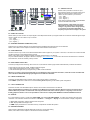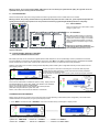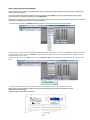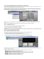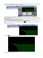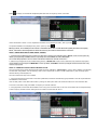
1
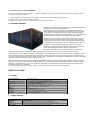
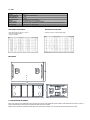
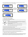
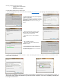
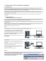
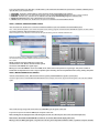
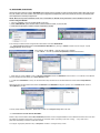
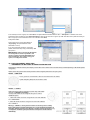
2013
USER´S MANUAL
BP-218DA
HIGH POWER 2X2500W SELFPOWERED
SUBWOOFER SYSTEM
REMOTE MONITORING AND CONTROL
GLOSARY
1.- Safety Instructions .................................................................................................. Page 5
2.- Declaraction on Conformity ................................................................................... Page 7
3.- Introduction to Owner´s Manual ............................................................................ Page 8
4.- System Overview .................................................................................................... Page 8
5.- DOUGLAS-8 Line-array.......................................................................................... Page 9
6.- BP-212 Subwoofer ................................................................................................. Page 11
7.- MX-8000D Amplifier ............................................................................................... Page 12
8.- MX-8000D Rear Panel22222222222222222..22222..222 Page 13
9.- MX-8000D Front Panel 222222222222222222222.22.2... Page 14
10.- Front Panel Display Control
Factory Presets Selection 2222222222222222222.2..22... Page 14
11.- Musicson Dsp Control Software 22222222222222.................22 Page 16
11.1.- Introductionn. Star Network Tipology 2222222........................... Page 16
11.2.- Musicson DSP Control Software Installation22222.222...22.. Page 16
12.- Musicson Dsp Control Software Management .................................................... Page 17
12.1.- Introduction ............................................................................................... Page 17
12.2.- MDCS Quick Start. Connecting one MX-8000D channel 2.2222..2 Page 17
13.- Gouping Functions................................................................................................... Page 23
14.- Factory Presets Selection
Depending on Douglas-8000 Configuration 22222222222222.22 Page 25
15.- Douglas-8000 Rigging System ............................................................................... Page 27
15.1.-Rigging System Overview ............................................................................ Page 27
15.2.-Optional Accessories ................................................................................... Page 28
15.2.1.- Elevation Frame 222222222222222.2222.22. Page 28
15.2.2.- Elevation Stand 22......................................................................... Page 28
15.2.3.- Douglas-8000 Tower 22222222222222222222 Page 29
15.2.4.- Grazier 2222222222222222222222222.... Page 32
15.2.5.- Base with Wheels for Tower 222222222222222..2 Page 33
15.3.- Douglas-8000 Stacked System Assembly 2222222222222... Page 33
15.4.- Douglas-8000 Elevation System 222222222222222222. Page 34
15.5.- Douglas-8000 Fligh-Case 222222222222222222222.. Page 36
16.- Douglas-8000 Connections 22222222..22222222222222..2 Page 36
17.- Douglas-8000 System Configuration examples 222222222222222 Page 38
18.- Limted Warraty............................................................................................................ Page 39
DOUGLAS-8000
COMPACT LINE-ARRAY SYSTEM
1.- Safety instructions for admittance in the product's User's Manual
• Read the information for use (user manual).
• Please keep the user manual in a safe place during the lifetime of the product. The user manual
forms an integral part of the product. Reselling of the product is only possible if the user manual is
available. Any changes made to the product have to be documented in writing and passed on to
the buyer in the event of resale.
• Heed all warnings.
• Follow all instructions.
• Do not use this product near water (for example, in damp rooms or near a swimming pool).
• Clean only with dry cloth.
• Do not cover the heat sink. Install in accordance with the user manual.
• Do not install near any heat sources such as radiators, heat registers, stoves, or other apparatus
that produce heat.
• Protect the power cord from being walked on, pinched or damaged in any other way. Pay
particular attention to plugs and the point where they exit from the Amplifier Unit.
• The product may only be used in accordance with the information provided in the user manual.
Before and during the usage of the amplifier please ensure that all recommendations, especially
the safety recommendations in the user manual, are adhered to. The Amplifier Unit is designed for
the amplification of pulsed audio signals and the Amplifier Unit should only be connected to
speakers with an average impedance that is not lower than the impedances specified in the User's
Manual.
• Do not place the product on an unstable cart, stand, tripod, bracket, or table. The device may fall,
causing serious injury, and serious damage to the device itself.
• The Amplifier Unit can only be disconnected from the power supply by removing the plug, which
must be freely accessible at all times. Unplug this Amplifier Unit during lightning storms or when
unused for long periods of time.
• Refer all servicing to qualified service personnel.
Damages that require service
Unplug the Amplifier Unit from the mains supply and refer to your dealer/distributor or other authorised
repair workshop. Servicing is required when
1. The power-supply cord or plug has been damaged,
2. Liquid has been spilled or objects have fallen into the amplifier,
3. The amplifier has been exposed to rain or moisture,
4. The amplifier has been dropped or suffered damage in any other way,
5. The amplifier exhibits a distinct change from its normal function or performance.
Servicing
Do not attempt to service this product yourself. As opening or removing covers may expose you to
dangerous voltage or other hazards, the amplifier may only be opened by qualified personnel. Please refer
to your dealer/distributor.
Servicing and Replacement Parts
All service and repair work must be carried out by an authorised dealer/distributor. When replacement
parts are required, please ensure that the dealer/distributor only uses replacement parts specified by the
manufacturer. The use of unauthorised replacement parts may result in injury and/or damage through fire or electric shock or other electricityrelated hazards.
Safety Check
Upon completion of any service or repairs to this product, ask the dealer/distributor to perform safety
checks to determine that the amplifier is in proper operating condition.
Read the information for use
When shipping the product, always use the original shipping carton and packing materials. For maximum
protection, repack the unit as it was originally packed at the factory.
Environments
Use this product only in E1, E2, E3 or E4 environments according to EN55103-2
“Electromagnetic compatibility – Product family standard for audio, video and audio-visual and
entertainment lighting control apparatus for professional use – Part 2: Immunity”
Ventilation and heat sink
The heat sink is provided to ensure reliable operation of the Amplifier Unit and to protect it from
overheating. The heat sink must not be blocked or covered. This product should not be installed unless
proper ventilation is provided or manufacturer’s instructions have been adhered to.
Water And Moisture
Do not use this product near water (for example, in damp rooms or near a swimming pool).
Cleaning
Unplug the Amplifier Unit from the wall outlet before cleaning. Do not use liquid or aerosol cleaners.
Power-cord Protection
Power supply cords should be routed so that they are not likely to be walked on or pinched by items
placed upon them or against them, paying particular attention to cords and plugs, and the point where
they exit from the Amplifier Unit.
Lightning
For added protection of the product during lightning storms, or when it is left unattended and unused for
long periods of time, unplug it from the wall outlet. This will prevent damage to the product due to
lightning and power-line surges. Disconnection from the mains power supply can only be achieved by
removing the plug from the mains socket and by external disconnection of all poles from the mains.
Interference of external objects and/or liquids with the appliance
Never push objects of any kind into this product through openings as they may touch dangerous voltage
points or short out parts that could result in a fire or electric shock. Never spill liquid of any kind on the
amplifier.
Accessories
Do not place this product on an unstable cart, stand, tripod, bracket, or table. The product may fall,
causing serious injury, and serious damage to the product. Any mounting of the product should follow the manufacturers instructions, and
should use a mounting accessory recommended by the manufacturer.
Connecting
When you connect the Amplifier Unit to other equipment, turn off the power and unplug all of the
equipment from the supply source. Failure to do so may cause an electric shock and serious personal
injury. Read the user's manual of the other equipment carefully and follow the instructions when making
the connections.
Sound Volume
Reduce the volume to minimum before you turn on the amplifier to prevent sudden high levels of noise
which may cause hearing or speaker damage.
SPEAKON connectors
WARNING: SPEAKON connectors marked with the lightning flashes indicate high voltages that are
potentially life threatening.
Wiring to these terminals requires installation by an instructed person and the use of ready-made leads or cords.
Custom wiring should only be carried out by qualified personnel.
To prevent electric shock, do not operate the product with any of the conductor portion of the speaker
wire exposed.
NOTE: For reasons of safety and performance, use only high-quality fully insulated speaker cables of
stranded copper wire. Use the largest wire size that is economically and physically practical, and make
sure the cables are no longer than necessary.
Precautions when connecting to MAINS IN and MAINS LINK
When mounting or connecting the product always disconnect it from mains. Only connect the product to
an appropriate AC circuit and outlet, according to the requirements indicated on the rating plate.
If a power cut occurs while the amplifier is switched on, it will restart automatically once the power supply
has been restored. All settings prior to the loss of power will be maintained.
IMPORTANT: Always connect the Product to mains through the MAINS IN connector on the Amplifier Unit.
IMPORTANT: Always use ready-made mains cables with original POWERCON connectors when connecting the product to mains.
IMPORTANT: When disconnecting the Product from the mains, always disconnect at the mains end first,
before disconnecting the PowerCon connector at the Product end.
IMPORTANT: Only connect additional Products to the MAINS LINK connector keeping within the specified power rating. Always use
ready-made mains link cables with original POWERCON connectors.
DO NOT REMOVE MAINS CONNECTOR GROUND, IT IS ILLEGAL AND DANGEROUS.
2.- Declaration on conformity - international EMC directives
For admittance in the product's User's Manual
The purpose of this section is to state the important declarations on conformity in accordance with
international EMC and EMI directives, which must be entered into the User's Manual for the final selfpowered loudspeaker.
EC Declaration of Conformity in accordance to EC Directives
electro-magnetic compatibility (Council Directive 89/336/EEC,
as amended by Directives 92/31/EEC and 93/68/EEC);
low-voltage electrical equipment (Council Directive 73/23/EEC )
This product conforms to the following standards:
EN55103-1 Emission
EN55103-2 Immunity
The operating conditions and application environments presupposed in the information for use (user
manual) are to be kept accordingly.
3.- INTRODUCTION TO OWNERS MANUAL
This Owner´s Manual has been divided in 3 Sections to facilitate user right an easier comprehension about his product in order
to obtain maximum performance:
1.- Product Manual; in which user can find all points related with final assembled product Operation.
2.- DSP Musicson Dsp Control Software ( MDCS )
3.- Ethernet connection: Control, Grouping and On-Line Monitoring Signals
4.- SYSTEM OVERVIEW
BP-218DA is a 6º order Double Band-pass design HIGH-POWER subwoofer
featuring 2 twin 18” long excursion speakers.
BP-218DA features a Input DSP module with most advanced technology (
96KHz Sample Frequency and 64 bits digital processing ) and a unique new
3rd Generation 2 x 2400W Class D Power modules with Double Universal
Switch Mode Power Supply for a world-wide operation in a range between 85V
and 268V delivering consistent power world-wide, fully self-protected.
Designed as very low Frequency reinforcement for all Musicson Line-array
Systems as well as any other Point Source system. BP-218DA will deliver
very high SPL levels from 34Hz to 80Hz using its dedicated OMNI directional
or CARDIOID Factory Presets with a minimum optimized speaker excursion.
BP-218DA has been designed with large port tunning area to avoid air
turbulences, undesirable noises and distortions when using high amounts of
power optimizing Response and SPL at very low Frequencies.
It´s also available a free, Windows and MAC based, Input DSP module Control and Monitoring software platform allowing FOH engineer to
configure BP-218DA system in a STAR NETWORK to have full Control and real-Time on-line Level and Limiters status monitoring.
Using Musicson Control and Monitoring Software, FOH Engineer can configure and control each star networked cabinet. It is allowed to select
between all available Factory Presets including Omni-Directional or several Cardioid pre-configured modes. Even, Engineer is also allowed to
modify Input Gain, Delay and X-Over filters to make new polar pattern configurations. It´s also allowed to select different Low-Pass X-Over filters
to use BP-218DA Subwoofer with any kind of full-range system.
BP-218DA features 2 twin long excursion 18” speakers assembled with a extremely powerful ceramic magnet capable to handle over 2000W
Peak each. This devices has been designed with Double-sided Voice coil as well as a Double centering spider system to optimize mechanical
stiffness and wire passive cooling. In such way, Impedance value remains constant even with very high input signal levels minimizing power
compression due voice coil temperature.
As a protection against humidity, rain, dust, L Musicson enforce 18” cones with a durable bi-component treatment.
ESPECIFICATIONS
1.- CABINET
Frequency Response
Power Handling
SPL
33Hz – 80Hz ( ± 3 dB )
Low-pass filter DSP adjustment and Preset dependant
2 x 18” Special cone treatment, 4” (100mm) Double-sided Voice Coil.
Double centering spider system
2 x 1600W AES / 2 x 2200W Peak
105dB ( 2.83V@1m ) / 145dB ( Peak )( to be confirmed )
Dimensions
Wight
Construction
Finishing
Front grille
Hardware
( Height x Width x Depth ) : 586x1380x860 mm
88Kg
18mm Marine Plywood
Black color painting Polyurea based
2mm Perforated Steel Black Exopy painted
12 x 220mm Steel handles.
Components
2.- POWER MODULE
Output Power
Output Voltage
S/N Ratio
Protections
2 x 2500W Continuos / 2 x 3600W Peak Clase D 3a Generación
2 x 160Vp loaded
Better than 120dB (A-weighted, 20Hz–20KHz, con carga de 8Ω )
Input Limiter, Short-circuit, DC in Outputs, under&over voltage, Temperature
Mains Voltage
Universal Mains, Automatic selection 85 – 268VAC 50/60Hz
3.- DSP
DSP Processing
Latency
Signal Connectors
Nominal Input Level
Max. Input Level
Network Connector
Network
Remote Control
Network Control
96KHz sample frequency, Mixed-mode 64 bit.
600 µs
XLR Female / XLR Male (Link)
+6dBu
+23dBu
Ethercon RJ/45, Cat-5 and USB
10/100Mb Ethernet Star configuration
Via Display and PC ( User Software included )
Input Level, Mute, Input Delay ( up to 800ms ), Input Limiter, Input/Output Signals Monitor
Dinamic Range
120dB (Input) / 117dB (Outputs)
FREQUENCY RESPONSE
IMPEDANCE RESPONSE
BP-218DA Ferquency response ( 1W/1m )
Active X-Over filters applied
Anechoic conditions
Impedance using 4V constant output voltage
MEASURES
8.- MX-8000D REAR PANEL.
Next, User will find a quick guide about all connectors and controls in BP-218DA back panel. Please, read carefully all this points to ensure a
proper understanding of all components related with DSP and Power modules.
Please, follow instructions and read carefully advices and warnings comments. Only one channel will be described in this section
1
2
3 4
5 6 7
8
8.1.- AUDIO IN CH1/CH2
9
E
D
AO
DM
8I
1
2
-N
PM
BO
E
D
AO
DM
8
1I
2N
PM
BO
10
Neutrik XLR-3 pin female connector for Input
Signal to DSP module. Input signal module use a
electronic balanced signal to reject noises on
cables. This are codes for 3 pin connector:
- pin 1 : GND
- pin 2 : Signal ( + )
- pin 3 : Signal ( - )
Under special customer request, digital AES/EBU
inputs are available in BP-218DA.
Warning!: Please, check that all your signal
cables follows right codes to avoid polarity
changes. If any of this cables change polarity
in any cabinet, an important degradation in
frequency response and coverage in all system
will occur.
8.2.- AUDIO OUT CH2/CH2
Neutrik XLR-3 pin male connector for Output Signal to next selfpowered cabinet. Input signal module use an electronic balanced signal to reject
noises on cables. This are codes for 3 pin connector:
- pin 1 : GND
- pin 2 : Signal ( + )
- pin 3 : Signal ( - )
8.3.- ETHERNET NETWORK CONNECTOR ( RJ45 )
RJ45 Ethercon for DSP Star Network Control and Monitoring capabilities using Musicson Dsp Control Software.
Please, refer to DSP Controls Chapter and Musicson Dsp Control Software in this Manual
8.4.- USB CONNECTOR
Use this connector only in case of new DSP Software Release Version appear for your system. In this case, a new version of Firmware for DSP
should be upload for Control and Monitoring functions.
Please, refer to DSP Controls Chapter and DSP Command Center Software in this Manual.
Any new Software Release, will appear in Musicson webpage ( www.musicson.com ) in which user will find concrete instructions to download
and Install them, as well as necessary Factory Presets.
8.5.- INPUT SIGNAL LEVEL LEDs
5 leds for Input Signal Gain Monitoring. When switch on unit, all leds will constantly light until all initial DSPs test procedures are finished.
3 Green leds for Input signal for -40dB, -20dB and 0dB Input signals.
1 LIMIT Yellow led that lights when Input Limiter is acting.
1 CLIP Red led that lights when Input signal arriving to DSP module is distorted.
Warning!: To ensure a good sound quality with very low distortion levels and protect transducers, CLIP red led never should be ON.
User is allowed to Remote Monitoring Input Signal Level via Musicson Software.
8.6.- “MENU” PUSHBUTTON
Pushbutton for DSP MENU Options. Please, refer to DSP Controls Section in this Manual.
Press “MENU” pushbutton to select most convenient Factory Preset depending on BP-218DA system configuration.
8.7.- “EXIT” PUSHBUTTON
Pushbutton for EXIT from DSP MENU Options. Please, refer to DSP Controls Section in this Manual.
Advice: Supplied Musicson Software is a valuable tool for Monitoring and Control Signals. Musicson strongly recommend to use
Software whenever possible. You will find all necessary information and control over the system in a very easy to use and user
friendly graphical interface. Limit screen pushbuttons and controls to display UNIT NAMES and FACTORY PRESETS selected.
8.8.- DISPLAY
It´s a User Interface to inform in 2 lines about “UNIT NAME” and selected FACTORY PRESET. It´s a blue color backlit screen with black
characters. User is allowed via Musicson Software in “Hardware” – “Configure” – “Display” to choose between 3 display configuration:
1.- ON: Default configuration. Display backlit remains always ON.
2.- OFF: Display backlit will change to OFF.
3.- DIMM: Display backlit dimmer. Will reduce intensity compared with standard ON position.
8.9.- ENCODER GAIN/EDIT
Total Encoder for EDITING and SELECTING DSP functions by pushing and rotating.
Please, refer to DSP Controls Chapter in this Manual for further information
Warning!: Please, do not select extreme INPUT GAIN values. It will sure distort your system Sound quality. As a general rule for an
optimized Sound, please Factory Presets selected Gain.
9.7.- COOLING WINDOWS
Placed over Rear panel. Rear panel cooling windows let inside 2 high performance fans to intake fresh air from outside.
Warning!: Please, keep cooling windows without any obstacle that may inhibit air flow. In that case, power amplifier temperature will
quickly increase limiting output power for its own protection and reducing significantly BP-218DA performance and quality.
E
D
AO
DM
8
1I
2N
PM
BO
8.11.- ON-OFF SWICHT
Switch On and Off unit. In ON Position, switch
will light in green color.
8.12.- AC LINE INPUT
12
11
BP-218DA amplifier features a 32 Amperes
Neutrik Powercon for AC Mains due it´s high
output power. Musicson supply an AC Mains
cable cord assembled together 32 Amperes
Neutrik Powercon Connector using a correct
wire sizes.
Warning!: Do not replace supplied AC
cable cord by others with less section: this
will not support total amplifier consumption. In case of using any other connector to plug unit to AC Mains, please be sure it can
support 32 Amperes.
10.- FRONT PANEL DISPLAY CONTROL
FACTORY PRESETS SELECTION
BP-218DA Input DSP can be controlled via supplied Musicson DSP Software or via front panel display controls: pushbuttons and encoder.
Front panel Display control options will be described in this section. Both “Menu” and “Exit” pushbuttons feature a double RED and GREEN
leds to check functions. There is also a total encoder ( rotate and push functions ) to select and confirm DSP parameters.
Selection and Loading most convenient Factory Presets depending on BP-218DA system configuration basically are main functions of rear
panel display controls.
As soon as system is switched on and during first 15 seconds, DSP and power
modules start all initial procedures to check all functions and load all parameters
corresponding to last loaded Preset.
During this time, no sound will come out from system and all Input Signal Level leds
will Light. Also,
message
“Initializing2 “ will
appear in system Display.
As soon as this initial check is finished and system is ready , display will show
last loaded PRESET as well as UNIT NAME. UNIT NAME is user selectable
and can be changed via Musicson SOFTWARE.
Display will show last Factory Preset selected. Also will keep all DSP
parameters configured last time system was used.
Please, refer to DSP Command Center Software in this Manual
CHANGING FACTORY PRESETS
Please, follow next steps to change to most convenient Factory Preset depending on BP-218DA system configuration ( refer to BP-218DA
CONFIGURATION on this Manual ) using front panel display controls:
1.- Push “MENU” and rotate Encoder “GAIN/EDIT” until most convenient Factory Preset appear in display screen:
------------------------
Sequence for Number and Name Factory Presets is as follow:
PRESET Nº1 : OMNI MODE ----- PRESET Nº 2 : CARDIO 1 ----------- PRESET Nº 3: CARDIO 2
PRESET Nº 4 : CARDIO 3 ------- PRESET Nº 5: CARDIO 4 ------------ PRESET Nº 6: OM LP-100Hz
The other 74 remaining PRESETS are free for user. Correct way to create new USER PRESETS is via MUSICSON DSP CONTROL
SOFTWARE. Please, refer to Musicson DSP Control Software in this Manual.
2.- Once displayed most convenient Factory Preset: Push Encoder “GAIN/EDIT” .
3.- System will ask to confirm loading process. Rotate then Encoder GAIN/EDIT to select “Yes”; words will change to capital leters.
Push Encoder GAIN/EDIT
once more. DSP will load
selected Factory Preset.
In case of a mistake in Factory Preset selection, user is allowed to push “EXIT” pushbutton to go back to previous sequence.
Finally, selected Factory Preset will be displayed on front panel DSP screen
11.- MUSICSON DSP CONTROL SOFTWARE
11.1.- INTRODUCTION. STAR NETWORK TIPOLOGY
MUSICSON BP-218DA DSP Controlled Subwoofer offers the possibility to design a Star Network configuration via Etherconn RJ45 already
supplied and installed in Input DSP Board.
A Star Network is a local area network ( LAN ) in which all nodes ( BP-218DA units ) are directly connected via
CAT5 cable to a common central Computer. With this Network topology, all BP-218DA will be WIRED or
WIRELESS linked to Computer by using a Hub or a Switch or a Musicson PWM-15; a 15-Port Wireless Ethernet
Switch , so it´s very easy to add or remove connected units.
In a Star Network, a cable failure will isolate ONLY the unit linked to computer with this cable. All other devices will
continue to function normally.
If any unit connected in this Network goes down, none of the other units will be affected.
All signals coming from / to any device to central computer goes directly without crossing through any other device
in the net so, communication speed is highest compared with other network topologies.
MUSICSON DSP CONTROL SOFTWARE, supplied with BP-218DA, allows user both:
1.- On-Line real-time INPUT PARAMETERS CONTROL over all BP-218DA connected in the network, including FACTORY PRESETS loading
and GROUPING Functions. Please, refer to MCDS Section in this Manual.
2.- On-Line Real-Time Input/Output Signals and Limiters Monitoring over all BP-218DA units connected in the network, as well as each Output
channel Impedance Load and Power modules Temperature. Please, refer to MDCS Section in this Manual.
MUSICSON DSP CONTROL SOFTWARE ( MDCS ) allows user to open as many Monitoring and Control windows as BP-218DA units
connected in the network. User can assign a UNIT NAME to any Amplifier in network ( It will also appear in front panel Display ) to identify all
units.
Software detects automatically all IP Addresses in the net and display all information required in opened window.
User can open or close each Amplifier Channel Control or Monitoring window as well as leave all them opened at same time.
11.2.- MUSICSON DSP CONTROL SOFTWARE INSTALLATION
MUSICSON strongly recommend to install MUSICSON DSP CONTROL SOFTWARE for all BP-218DA selfpowered subs for Monitoring and
Control Input/Output Signals via CAT5 cable ( wired through an Ethernet Switch or wireless by using new Musicson PWM-15 module ). It´s a
powerful, friendly and easy to use system Remote Control tool including a well designed Graphical User Interface featuring also important
parameters monitoring such as both amplifiers channel Temperature and Impedance Load. Musicson DSP Con Software.
Following operating Systems are supported:
Windows XP with Service Pack 2
Windows 7
Mac OS-X 10.5.8 or higher
To install Software, please, follow this simple steps:
1.- After downloading Musicson DSP Control from Musicson website ( www.musicson.com ) open package. The installer will guide you through
installation procedures.
2.- Please, accept terms in the Licence Agreement
by clicking in right place.
Maybe, in some moments of installation procedure,
a message from windows can appear if you have a
firewall activated.
Please, go on with installation and select go on
anyway.
3.- Select the folder where you wish to have
Musicson DSP Control Software installed:
By default: Musicson\DSPControl
4.- Select NEXT and go on with installation
process.
5.- Now, installation will start.
System will need some minutes to finish
installation process.
6.- Once installation is finished, installer will ask
to install also Microsoft VisualC++ Runtime to
run software correctly; please accept installation
as shown in next figures.
9.- Finally, accept Microsoft License Terms and click on “Install”. After finishing all this steps, you will see a new icon in your Desktop to launch
Musicson DSP Control Software.
Warning!: On some Windows 7 versions, user will need to run the Software as “Administrator” to connect with hardware correctly. To
change to this mode, click with right pushbutton of your mouse and select “Properties”. Then, select “compatibility” and finally “Run
this program as Administrator”.
12.- MUSICSON DSP CONTROL SOFTWARE (MDCS) MANAGEMENT
12.1.- INTRODUCTION
BP-218DA DSP Controlled Selfpowered subwoofer is fully equipped from MUSICSON with Ethernet solution via RJ45 connectors in its back
panel as well as MUSICSON DSP CONTROL SOFTEWARE for network capabilities to enable complete filters configuration, control,
convenient cabinets grouping and monitoring solutions. With its intuitive and easy-to-use graphical interface, Musicson DSP Control Software
provides remote ( wired or wireless ) access to load also FACTORY or USER PRESETS.
Each BP-218DA RJ45 Ethernet connector in backplate must be connected to a 100BaseT Ethernet switch using a standard CAT-5 cable.
Personal Computer to run control with Musicson Dsp Control Software must also be connected by 100BaseT connector to the switch or using a
wireless access point on the same network.
Using a wireless access point to manage Network will require additional TCP/IP protocols in user Computer as well as specific Ethernet
configurations.
12.2- MDCS: QUICK START
CONNECTING BP-218DA FOR THE FIRST TIME
Even if you have experience in handling control and monitoring software systems, it´s hardly recommended for BP-218DA users to follow this
instructions with initial test configurations starting with simplest networking. Musicson Dsp Control Software is a powerful and reliable control
and monitoring platform which can be used in any Musicson system using Input Dsp´s modules.
Note: To avoid any communication errors, please, avoid connecting the switch to any other Ethernet equipment than speaker/s and
Control Computer.
Warning!: If you are using a wireless access point with a Ethernet switch to control and monitoring your BP-218DA system, please,
NEVER use 100BaseT network connector in your Control Computer for other Network uses.
Follow next steps for a single BP-218DA unit network:
STEP 1
Connect a MX-8000D Amplifier to Control PC using a USB A-USB B ( Universal Serial Bus ) cable. First time this connection is handled, all
necessary drivers for a correct communication between Control PC and Hardware will be installed.
BP-218DA
E
D
AO
D
8M
1I
2N
PM
BO
1.- Use a standard USB A – USB B ( Universal Serial Bus ) cable for
drivers download. In this way, we will use one USB connector of one
channel in MX-8000D Back Panel to one of USB Ports in Computer.
Please, note that DCCS will install all necessary drivers for Computer to
detect the device and will assign automatically the most convenient
COMM Port for a successful communication.
USB CONN.
It will be necessary to switch OFF your BP-218DA amplifier for a correct
drivers installation.
Only for first time.
USB A-USB B CABLE
CONTROL LAPTOP
BACK PANEL
2.- Using a Network Switch we will need to use for several BP-218DA system, or, as better solution, our Musicson PWM-15 ( a 15 Port Wireless
Ethernet Switch )
BP-218DA
E
-1 D
A
DO
8M
1I
2
-N
PM
BO
In this case, user will connect an unmanaged 100BaseT network
Switch to Ethernet connector in MX-8000D back panel with a standard
CAT-5 cable.
NETWORK
SWITCH
Then, connect the Computer to the Ethernet Switch with another
standard CAT-5 cable as shown in figure
CAT 5
CABLE
CAT 5
From now, we will use from now this second way as it will be the
correct way to connect any MX-8000D amplifier system to Control
Computer; wired or wireless.
Finally, power up your BP-218DA amplifier.
CABLE
BACK PANEL
CONTROL LAPTOP
STEP 2
Launch MUSICSON DSO CONTROL SOFTWARE in Windows or MAC by clicking twice in the icon. Then, Musicson Dsp Control Software will
detect automatically, all devices connected in the network. Unit Name indicator will show a GREEN COLOUR besides detected unit if
connection is “Active”. If a YELLOW COLOUR appears in Control
Center screen, please, check all network connection, configuration
and cables: there is a communication problem and you will not be
able to use Monitoring and Control Software.
In this case, 2 BP-218DA units ( BP218DA-1 and BP218DA-2 ) will be detected. Main MENU will open Musicson CONTROL CENTER panel in
upper-left side of your Computer screen.
1.- UNIT NAME : BP218DA-1 and BP218DA-2. User is allowed to change UNITS NAME through Software.
2.- REFERENCE : B8:96:74:00:11:45 and 00:50:C2:76:AA:F9. This is a code automatically detected. User doesn´t need to introduce
3.- ADDRESS: 192.168.2.102 y 192.168.2.100. IP Address for both BP-218DA automatically assigned to networked Units.
4.- GROUP: Not Grouped. Please, refer to GROUPING Units in this Manual.
5.- LAUNCH: Press with mouse over “Double Arrow” to open this unit CONTROL and MONITORING Window
STEP 3. CONTROL AND MONITORING PANELS
Click with mouse over “Double Arrow “ in Musicson CONTROL CENTER to open units CONTROL and MONITORING panel.
Then, 2 new panels will appear in your Control Computer monitor showing progress of Networked Unit PROGRESS together with UNIT CODE,
and creating CONTROL AND MONITORING panel views.
After a brief period of time, Musicson Control Center will open Monitoring panel for selected networked unit.
As shown in picture, there is a GREEN indicator in besides “LINK”.
This mean that communication between networked unit and Control
PC is active.
NOTE: If indicator changes to RED color, means that
communication is lost. Please, check all network system
connections until GREEN color appear again.
Warning!: It is NOT ALLOWED to access to X-OVER, OUT1, OUT2, OUT3 control panels for any changes. This panels contain all
information and adjustments for each 3 ways to optimize system including: X-Over and optimization filters, delay, limiting and phase.
STEP 4: MONITORIZING IN/OUT SIGNALS
User will control all INPUT, LOW , MID and HIGH OUTPUT signals by MONITORIZING this signals in opened panel.
Connect a signal source to selected Networked MX-8000D channel and play some music. Signal Levels will appear in Bar-Leds with GREEN
Lights
When Levels are High enough that Limiters start to act, YELLOW Lights will appear on Bar Leds.
If signal are so high that are distorted, RED Lights will appear on Bar Leds.
Note: Peak Signals are displayed on Bar Leds during few seconds. This will help user to fix more convenient Input Level.
Note: Please, note that IN1 and IN2 INPUTS are Linked so, in all cases, Bar leds will display same Level.
Warning!: Never let RED lights appear in any Bar Leds. This may cause important breakdowns either in speakers and power modules
STEP 5: SELECTING FACTORY PRESETS
User is allowed in any BP-218DA Dsp controlled to select most convenient Factory Preset depending on networked system configuration via
Musicson Dsp Control Software.
In this case, one BP-218DA unit will be loaded with Factory Preset Nº2 called “CARDIO 1” to deliver a CARDIOD Polar Pattern together
another BP-218DA unit loaded with PRESET Nº1 called “OMNI MODE”.
User will find in this Manual all necessary references for BP-218DA system to select most precise Factory Preset depending on most convenient
Polar Pattern ( Ominidirectional or Cardiod ) or Frequency Bandwith.
1.- Click with left mouse button on “PRESETS UNIT” and selected unit CONTROL panel will open all stored presets
2.- Select most convenient Factory Preset depending on BP-218DA system configuration. In this case, for CARDIOD polar pattern configuration
using 2 BP-218DA units, we wll choose “CARDIO 1 “ Factory Preset. This Preset will contain all necesary adjustments including X-Over and
optimization filters, Delay, Limiting,L
3.- Select now with your mouse “LOAD” screen in Section “PRESETS UNIT” to load this Factory Preset in DSP memory as shown in next
figure.
A new panel will appear showing “Synchronization Progress” while software is sending all parameters to DSP memory.
NOTE: As soon as Synchronization Progress is finished, selected Factory Preset name will be displayed in both:
- BP-218DA back panel display.
- PRESET UNIT panel in Musicson Software.
STEP 6: MONITORIZING IMPEDANCE LOADS AND MODULE TEMPERATURE.
Musicson Control DSP Software ( from now MDCS ) supplied with your BP-218DA allow also user through some complex algorithms monitor
each output channel LOAD IMPEDANCE as well as Amplifier Temperature.
Each Power Module in BP-218DA features all necessary Thermal Sensors placed in each output channel and also in Switch Mode Power
Supply. Musicson DSP Control Software ( MDCS ) will show this information at any time when “STATUS” led is GREEN. Concerning Amplifier
Temperature, Software always display most critical value ( highest Temperature )
For both Amplifier channel Temperature and Load Impedance Monitoring, please, select “Details” in “UNIT NAME” Section as shown in
picture.
Please, note that Load Impedance values can give an important information about each 18” transducers conditions.
STEP 7: CHANGING INPUT GAIN
User can increase or reduce from +12dB to MUTE, INPUT GAIN by 2 methods:
- Clicking on INPUT faders and dragging upwards or downwards or
- Introducing ( writing ) directly in IN window the desired level value.
IMPORTANT!: Please, try not to use extreme Input Gain values; use 0.0dB as a standard Gain. Please, note that a ±3dB Gain change
means twice the acoustic output compared with 0.0dB.
STEP 8: USING INPUT EQUALIZATION FILTERS
As previously commented, MDCS supplied with BP-218DA DSP Controlled selfpowered subwoofers allow:
1.- Input/Outputs Signals Monitoring ( refer to previous Manual Sections )
2.- Input parameters Control: X-Over and Optimization filters, Delay, Limiters and Compressors.
1.- Tap with mousse button over IN1 panel in MDCS. Control panel will appear in Control Computer screen:
MDCS features up to 10 Optimization filters ( including X-Over Low-Pass, High-Pass, Low-Shelf, Hi-Shelf, Notch, Allpass, Bandpass ) in each
BP-218DA. Available filters types are:
- BELL : Selectable in any Frequency with variable Q ( 0.2 to 20 ), and Gain ( between -12 and +12dB )
- NOTCH : Selectable in any Frequency with fixed Q=10 and G=-40dB
- ALLPASS: Selectable in any Frequency with variable Q ( 1 to 25 )
- LOW-SHELF: Selectable in any Frequency with variable Q ( 3 to 25 ) and Gain ( between -12dB to +12dB )
- HIGH-SHELF: Selectable in any Frequency with variable Q ( 3 to 25 ) and Gain ( between -12dB to +12dB )
- BAND-PASS : Selectable in any Frequency with variable Q ( 0.2 to 25 )
- HIGH-PASS : Selectable in any Frequency with variable Q ( 0.5 to 2 )
- LOW-PASS : Selectable in any Frequency with variable Q ( 0.5 to 2 )
2.- User can use either Equalization panel to configure necessary EQ. filters or clicking with mouse over each point in GRAPH and dragging
with left button of mouse pressed to select Filter Frequency center and Gain.
It´s possible to use PC mouse to adjust all EQ. filter parameters.
- Click with PC mouse LEFT button over desired EQ. filter number ( square symbol ) and, while holding on, move it upwards ( increase Gain ) or
downwards ( reduce Gain ).
- Click with PC mouse RIGHT button over EQ. filter number ( square symbol ) and, while holding on, move it to the right ( increase Q with
narrower .filter bandwidth ) or left ( reduce Q with wider filter bandwidth ).
User is allowed to switch Equalization filters ON and OFF in Real-time to check sound differences in order to make filters best choice by clicking
over blue square besides EQ filter: Blue color means EQ filter ON and no color means EQ filter OFF.
Size of Graphs can be increased for a more accurate data display by selecting
levels:
1.- First size level as shown in next figure
2.- Select again
to have a full Control PC screen Graph.
Select X screen will return to standard size.
in Left Upper side on screen. There are 2 screen size
Select
to display on each EQ filter all adjusted parameters such as Frequency Center, Q and Gain.
User is allowed also to “Save” or “Print” adjustments information in a Graphical Format file ( .PNG ) by clicking
An especific bandwidth can be displayed using “Zoom” option by clicking
.
.
Warning!: Please, do not attempt to use extreme or radical EQ. filters Gain. It could deteriorate system performance and quality
Please, note that this kind of adjustments should be used only as a audience areas features corrections.
STEP 9: USING INPUT DELAY AND SIGNAL LIMITER
1.- Input Signal can be delayed for time corrections in delay lines by entering most adequate value in “DELAY” screen in Control panel. By
default, Input signal delay is 0.00ms. Maximum Input Delay value will be 800ms that means 275 meters.
For an easier Delay adjustment, user can switch units between milliseconds, seconds, meters, feet,L
2.- Maximum Input Signal can be also Limited entering value on “LIMITER THR” screen to limit in that each 3 way máximum output power.
Limiter Release can be changed in “LIMITER REL” screen. By default, +12.00dBU.is minimum Input Signal Limiter that means each 3 way
maximum output power.
STEP 10: USING INPUT HIGH-PASS/LOW-PASS FILTER
There is a special Factory Preset designed for BP-218DA subwoofer ( PRESET 6: “OM LPF100Hz” ) using a 100Hz, 24dB/Oct, Linkwitz-Riley
Low-Pass filter. Using MDCS, user can select any other X-Over Low-Pass filter in order to use BP-218DA with any other full-range system
cabinets selecting most adequate LPF.
There are 2 methods to setup a LPF in MDCS:
1.- Using Input High-Pass and Low-Pass X-Over filters ( Butterworth, Bessel and Linkwitz-Riley types) available to user with slopes between 6
and 24dB/Oct in Control Panel.
User can easily switch X-Over filters ON and OFF by clicking over blue square: blue color means filter ON and no color means filter OFF.
To remove X-Over filters, simply write “OFF” in Frequency X-Over filter white box.
2.- Using High-Pass and Low-Pass filter available in each 10 Eq. points in Control Panel. In this case, X-Over filters will be configured through
X-Over Frequency and filter Q Factor. Next figure shows a 85Hz Low-Pass filter with Q=0.71.
13.-GROUPING FUNCTIONS
Working with large number of systems, GROUPING function allows user the possibility to make convenient Groups of BP-218DA units copying
from one “master” unit to rest of “Slave” units same Input configuration and adjustments. This function avoid user to enter in all individual units
same adjustments to manually configure them.
NOTE!: Musicson Dsp Control Software allows user to select NOT TO GROUP certain parameters to have individual control even
inside a configured GROUP.
1.- Click over “TOOLS” in Musicson Control Center panel Menu.
2.- Select “NEW GROUP” option and then write a convenient GROUP NAME. Confirm with OK.
3.- Follow this 2 simple steps to create as number of GROUPS as needed.
In this example, a GROUP will be configured with 2 BP-218DA units called “BP218DA-G”
3.1.- Select networked units to join in selected GROUP “BP218DA-G” by clicking in “SETUP” window as shown in figure. A panel
“Configure Group” will be opened
In this example, we will “Select2” both BP-218DA units in Network:
1.- Click “Select2” and will open Select Group Members screen selection Menu.
1.- Select with PC mouse in Name” column in Select Group Members screen first BP218DA-1 unit and click in “>” to add this unit to GROUP.
First unit selected will automatically go to Group Members screen.
2.- To add second BP218DA-2 to Group, we will follow same steps as before. Now, both BP-218DA units will be add to Group Members
screen.
Next figure shows both BP-218DA which Names are BP218DA-1 and BP218DA-2 change its “position” from “Available units” screen to
“Group Members” screen.
To finally accept GROUP configuration, please click on “OK” and “Configure Group” Menu will close.
3.2.- Parameters that should “NOT BE GROUPED”
Musicson Dsp Control Software allows NOT TO GROUP parameters inside a configured GROUP to have individual members control over them.
This feature is specially important when it is necessary to control EQ. Filters, Input Delay, Input Gain, Limiting,L or any other control
parameters individually in members inside same GROUP.
To configure “ungrouped” parameters tap “→Exceptions” window in “Configure Group” screen.
In this example, we will “ungroup” EQ. Filters PEQ in configured DOUGLAS-8000 GROUP. After “→Exceptions” is selected, user will be
requested to select exception through “Select Exceptions” Menu screen as shown in figure. Tap “All” and select which parameter would you
like to “ungroup” to have individual control. In this case EQ. Filters PEQ.
Finally Select “OK”.
Figure will show the process while MDCS is
“ungrouping” all Input PEQ filters inside
“BP218DA-G” Group.
If any other parameter should be “ungrouped”,
please, follow same steps using consecutively “All”
popup menu.
IMPORTANT!: Please, note that all adjustments
and configurations made in Input DSP´s, will
remain in memory each time BP-218DA unit is
switched ON again. Check before using your
system, all configuration loaded.
14.- FACTORY PRESET SELECTION
DEPENDING ON BP-218DA SYSTEM CONFIGURATION
Both Musicson Software and rear panel display controls allow user to select most convenient Factory Presets depending on BP-218DA system
configuration.
Please, follow next guide to select Factory Presets to deliver highest performance with your system:
PRESET 1: OMNI MODE
Factory preset Nº1: Standard BP-218DA with Omnidirectional Polar Pattern.
System Frequency Response: From 33Hz to 70Hz.
PRESET 2 : CARDIO 1
Select this Factory Preset to configure a system using 2 BP-218DA
units with a CARDIOD Polar Pattern.
A Group of BP-218DA can be configured like figure to create a
CARDIOD system.
1.- FRONT BP-218DA should be configured with FACTORY PRESET
Nº1 : “OMNI MODE”
2.- REAR BP-218DA should be configured with FACTORY PRESET
Nº2 : “CARDIO 1”
Warning!: “CARDIO 1” factory Preset contains all necessary X-Over and Eq
filters, Delay, Phase and Gain parameters for a correct Cardiod Polar Pattern. If
separation between front and rear cabinets or number of boxes proportion ( 1:1 )
is changed or modified, system performance and response will be reduced
dramatically.
PRESET 3 : CARDIO 2
Select this Factory Preset to configure a system using 2
BP-218DA units with a CARDIOD Polar Pattern.
A Group of BP-218DA can be configured like figure to
create a CARDIOD system.
1.- FRONT Nº1 BP-218DA should be configured with
FACTORY PRESET Nº1 : “OMNI MODE”
2.- FRONT INVERT BP-218DA should be configured with FACTORY
PRESET Nº2 : “CARDIO 2”
Warning!: “CARDIO 2” factory Preset contains all necessary X-Over and Eq filters, Delay, Phase and Gain parameters for a correct
Cardiod Polar Pattern. If position between front and inverted cabinets or number of boxes proportion ( 1:1 ) is changed or modified,
system performance and response will be reduced dramatically.
PRESET 4 : CARDIO 3
Select this Factory Preset to configure a system using 3 BP-218DA units with a
CARDIOD Polar Pattern.
A Group of BP-218DA can be configured like figure to create a CARDIOD
system.
1.- Both FRONT BP-218DA should be configured as a standard subwoofer
using FACTORY PRESET Nº1: “OMNI MODE”
2.- REAR BP-218DA should be configured with FACTORY PRESET Nº 4 :
“CARDIO 3”
Warning!: “CARDIO 3” factory Preset contains all necessary X-Over and Eq filters,
Delay, Phase and Gain parameters for a correct Cardiod Polar Pattern. If position
between front ( 2 units ) and rear ( 1 unit ) cabinets or number of boxes proportion (
2:1 ) is changed or modified, system performance and response will be reduced
dramatically.
PRESET 5 : CARDIO 4
Select this Factory Preset to configure a system using 3 BP-218DA units with a CARDIOD Polar Pattern.
A Group of BP-218DA can be configured like figure to create a
CARDIOD system.
1.- Both FRONT BP-218DA should be configured as a standard
subwoofer using FACTORY PRESET Nº1: “OMNI MODE”
2.- REAR BP-218DA should be configured with FACTORY
PRESET Nº 4 : “CARDIO 4”
Warning!: “CARDIO 4” factory Preset contains all necessary X-Over
and Eq filters, Delay, Phase and Gain parameters for a correct
Cardiod Polar Pattern. If position between front ( 2 units ) and rear (
1 unit ) cabinets or number of boxes proportion ( 2:1 ) is changed or
modified, system performance and response will be reduced
dramatically.
PRESET 6 : OM LPF100Hz
Select this Factory Preset for a standard OMNIDIRECTIONAL BP-218DA Polar Pattern.
Using this Factory Preset, BP-218DA delivers a Frequency Response from 33Hz to 100Hz.
AS previously seen in this Manual, MDCS allows user to keep this 100Hz Low-Pass X-Over Frequency or changing it
through LPF parameter in INPUT screen to be used as Low Frequency reinforcement for any other Full-range system.
18.- MUSICSON LIMITED WARRANTY
MUSICSON products like subwoofer BP-218DA system are guaranteed for two years from the date of original purchase and covers all defects
in material and workmanship, including, enclosures, Power and DSP modules and devices.
All BP-218DA user must preserve original shipping cartons in case of unit should be sent to Factory. In other cases, Musicson will charge new
carton if needed.
In case of damaged cabinet could not be sent to Factory for checking or repairing, Musicson will supply all necessary parts to replace damaged
ones. Musicson Technical Department will be the last responsible to send pieces or repair any product under warranty after checking. Please,
do not ship any Musicson product to the factory without authorization.
Following aspects are not covered by warranty: product modifications, neglect actions, damages caused by improper use even during shipment;
Musicson warranty will not cover any non-authorized repair.
Please, contact Musicson for any further information about this section.
MUSICSON S.L
46920 Mislata, Valencia, Spain
www.musicson.com
[email protected]